US5736808A - Piezoelectric speaker - Google Patents
Piezoelectric speakerDownload PDFInfo
- Publication number
- US5736808A US5736808AUS08/577,279US57727995AUS5736808AUS 5736808 AUS5736808 AUS 5736808AUS 57727995 AUS57727995 AUS 57727995AUS 5736808 AUS5736808 AUS 5736808A
- Authority
- US
- United States
- Prior art keywords
- bender
- piezoelectric
- rigid structure
- piezoelectric speaker
- speaker
- Prior art date
- Legal status (The legal status is an assumption and is not a legal conclusion. Google has not performed a legal analysis and makes no representation as to the accuracy of the status listed.)
- Expired - Fee Related
Links
- 239000000463materialSubstances0.000claimsabstractdescription29
- 235000012431wafersNutrition0.000description29
- 238000003462Bender reactionMethods0.000description7
- 239000006260foamSubstances0.000description7
- 229920003023plasticPolymers0.000description5
- 239000004033plasticSubstances0.000description5
- 239000011263electroactive materialSubstances0.000description4
- 239000000919ceramicSubstances0.000description3
- 230000005684electric fieldEffects0.000description3
- 238000005538encapsulationMethods0.000description3
- 239000002033PVDF binderSubstances0.000description2
- 239000000853adhesiveSubstances0.000description2
- 230000001070adhesive effectEffects0.000description2
- 230000001419dependent effectEffects0.000description2
- 238000006073displacement reactionMethods0.000description2
- 229910052751metalInorganic materials0.000description2
- 239000002184metalSubstances0.000description2
- 229920002981polyvinylidene fluoridePolymers0.000description2
- 230000036316preloadEffects0.000description2
- 238000004804windingMethods0.000description2
- 229910001369BrassInorganic materials0.000description1
- 229910000831SteelInorganic materials0.000description1
- 230000001944accentuationEffects0.000description1
- 238000005452bendingMethods0.000description1
- 230000005540biological transmissionEffects0.000description1
- 239000010951brassSubstances0.000description1
- 238000006243chemical reactionMethods0.000description1
- 230000008878couplingEffects0.000description1
- 238000010168coupling processMethods0.000description1
- 238000005859coupling reactionMethods0.000description1
- 210000005069earsAnatomy0.000description1
- 230000000694effectsEffects0.000description1
- 239000013013elastic materialSubstances0.000description1
- 229910052746lanthanumInorganic materials0.000description1
- FZLIPJUXYLNCLC-UHFFFAOYSA-Nlanthanum atomChemical group[La]FZLIPJUXYLNCLC-UHFFFAOYSA-N0.000description1
- HFGPZNIAWCZYJU-UHFFFAOYSA-Nlead zirconate titanateChemical compound[O-2].[O-2].[O-2].[O-2].[O-2].[Ti+4].[Zr+4].[Pb+2]HFGPZNIAWCZYJU-UHFFFAOYSA-N0.000description1
- 229910052451lead zirconate titanateInorganic materials0.000description1
- 238000000034methodMethods0.000description1
- 239000000203mixtureSubstances0.000description1
- ZBSCCQXBYNSKPV-UHFFFAOYSA-Noxolead;oxomagnesium;2,4,5-trioxa-1$l^{5},3$l^{5}-diniobabicyclo[1.1.1]pentane 1,3-dioxideChemical compound[Mg]=O.[Pb]=O.[Pb]=O.[Pb]=O.O1[Nb]2(=O)O[Nb]1(=O)O2ZBSCCQXBYNSKPV-UHFFFAOYSA-N0.000description1
- 238000004806packaging method and processMethods0.000description1
- 229920000642polymerPolymers0.000description1
- 230000000644propagated effectEffects0.000description1
- 230000035945sensitivityEffects0.000description1
- 230000035939shockEffects0.000description1
- 239000007779soft materialSubstances0.000description1
- 230000005236sound signalEffects0.000description1
- 239000010959steelSubstances0.000description1
Images


Classifications
- A—HUMAN NECESSITIES
- A42—HEADWEAR
- A42B—HATS; HEAD COVERINGS
- A42B3/00—Helmets; Helmet covers ; Other protective head coverings
- A42B3/04—Parts, details or accessories of helmets
- A42B3/30—Mounting radio sets or communication systems
- H—ELECTRICITY
- H04—ELECTRIC COMMUNICATION TECHNIQUE
- H04R—LOUDSPEAKERS, MICROPHONES, GRAMOPHONE PICK-UPS OR LIKE ACOUSTIC ELECTROMECHANICAL TRANSDUCERS; DEAF-AID SETS; PUBLIC ADDRESS SYSTEMS
- H04R1/00—Details of transducers, loudspeakers or microphones
- H04R1/02—Casings; Cabinets ; Supports therefor; Mountings therein
- H04R1/028—Casings; Cabinets ; Supports therefor; Mountings therein associated with devices performing functions other than acoustics, e.g. electric candles
- H—ELECTRICITY
- H04—ELECTRIC COMMUNICATION TECHNIQUE
- H04R—LOUDSPEAKERS, MICROPHONES, GRAMOPHONE PICK-UPS OR LIKE ACOUSTIC ELECTROMECHANICAL TRANSDUCERS; DEAF-AID SETS; PUBLIC ADDRESS SYSTEMS
- H04R17/00—Piezoelectric transducers; Electrostrictive transducers
- H—ELECTRICITY
- H04—ELECTRIC COMMUNICATION TECHNIQUE
- H04R—LOUDSPEAKERS, MICROPHONES, GRAMOPHONE PICK-UPS OR LIKE ACOUSTIC ELECTROMECHANICAL TRANSDUCERS; DEAF-AID SETS; PUBLIC ADDRESS SYSTEMS
- H04R17/00—Piezoelectric transducers; Electrostrictive transducers
- H04R17/04—Gramophone pick-ups using a stylus; Recorders using a stylus
- H04R17/08—Gramophone pick-ups using a stylus; Recorders using a stylus signals being recorded or played back by vibration of a stylus in two orthogonal directions simultaneously
- H—ELECTRICITY
- H04—ELECTRIC COMMUNICATION TECHNIQUE
- H04R—LOUDSPEAKERS, MICROPHONES, GRAMOPHONE PICK-UPS OR LIKE ACOUSTIC ELECTROMECHANICAL TRANSDUCERS; DEAF-AID SETS; PUBLIC ADDRESS SYSTEMS
- H04R2217/00—Details of magnetostrictive, piezoelectric, or electrostrictive transducers covered by H04R15/00 or H04R17/00 but not provided for in any of their subgroups
- H04R2217/01—Non-planar magnetostrictive, piezoelectric or electrostrictive benders
- H—ELECTRICITY
- H04—ELECTRIC COMMUNICATION TECHNIQUE
- H04R—LOUDSPEAKERS, MICROPHONES, GRAMOPHONE PICK-UPS OR LIKE ACOUSTIC ELECTROMECHANICAL TRANSDUCERS; DEAF-AID SETS; PUBLIC ADDRESS SYSTEMS
- H04R2499/00—Aspects covered by H04R or H04S not otherwise provided for in their subgroups
- H04R2499/10—General applications
- H04R2499/15—Transducers incorporated in visual displaying devices, e.g. televisions, computer displays, laptops
Definitions
- the present inventionrelates generally to a loudspeaker, and lo more particularly to a loudspeaker that generates sound using piezoelectric material.
- the present inventionrelates to a loudspeaker using piezoelectric or electroactive materials.
- piezoelectric or electroactive materialssuch as the lead zirconate titanate family (commonly known as PZT) with all its variously substituted and doped relatives, electrostrictive ceramics such as certain compositions of lanthanum doped PZT (PLZT) or lead magnesium niobate (PMN), and piezoelectric polymers such as polyvinylidene fluoride (PVDF).
- the piezoelectric or electroactive materialmay be arranged in a variety of ways, including unimorph or bimorph benders. Benders are devices wherein the controlled strain of one or more layers is resisted by other layer or layers, resulting in a bending deformation. The most common benders are classified as unimorphs, which consist of one active layer, and bimorphs, which consist of two active layers. More recently another type of bender was introduced under the name of RAINBOWTM (Reduced and Internally Biased Oxide Wafer) and possessing certain attractive performance characteristics. The RAINBOWTM wafer is described in detail in co-pending application No. 08/021,367, entitled "Monolithic Prestressed Ceramic Devices And Method For Making Same," which is incorporated by reference herein.
- the speakers using a large diaphragm or conefeature high lows and low highs, while the speakers using a small diaphragm or cone have high highs and low lows.
- the present inventionavoids the problem of the known piezoelectric speakers by utilizing the acoustic properties of any rigidly attached structure.
- the rigid structuremay include a computer monitor housing, a television set, any welded structure such as an automobile cargo bay or file cabinet, a plastic box, a dry wall or building frame, a small appliance, or a bicycle helmet.
- an acoustical pressure with higher DB levelis generated by a significantly larger area of a driving object.
- an entire structurebecomes a speaker and in each application possesses numerous acoustical properties dependent upon the material and shape of the attached rigid structure.
- the feature of the present invention of utilizing an attached rigid structure for acoustical outputincludes an additional advantage that it can be of any planar shape to fit an enclosure volume.
- the piezoelectric speakercan fit within a slot, such as in case of a bicycle helmet application, or the piezoelectric speaker can fit within a thin layer space of approximately 0.040" in a computer keyboard application.
- a significant object of the present inventionis to provide a piezoelectric speaker that is easily and inexpensively manufactured. It is another object of the present invention to provide a piezoelectric speaker that is easily secured to an existing structure.
- the speakerincludes a rigid structure, a piezoelectric material bender, and a wave guide mounted to both the rigid structure and the bender and serving to interconnect the rigid structure and the bender.
- the wave guideis a fabricated from a rigid material and is mounted to the bender at approximately the geometric center of the bender.
- the bendermay also be encapsulated in a case.
- the rigid structuremay include a computer keyboard, a bicycle helmet or any other rigid structure.
- a feature of the present inventionis that the piezoelectric speaker is easily manufactured.
- the piezoelectric speakerhas a broad frequency range.
- Another feature of the present inventionis that the piezoelectric speaker is easily adapted to existing structures.
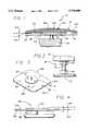
- FIG. 1is a cross-sectional front view of one embodiment of a piezoelectric speaker of the present invention
- FIG. 2is a front view of an alternative embodiment of a wave guide of mechanism of the piezoelectric speaker of the present invention
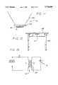
- FIG. 3is a perspective view of a bimorph bender of the piezoelectric speaker of the present invention.
- FIG. 4is a front view of the bimorph bender of the piezoelectric speakers of the present invention.
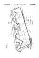
- FIG. 5is a perspective view of the piezoelectric speaker of the present invention in a computer keyboard application
- FIG. 6is a cross-sectional front view of the piezoelectric speaker of the present invention in a bicycle helmet application
- FIG. 7is a cross-sectional front view of the piezoelectric speaker of the present invention in an alternative embodiment of a bicycle helmet application;
- FIG. 8is a cross-sectional front view of the piezoelectric speaker of the present invention in another alternative embodiment of a bicycle helmet application;
- FIG. 9is a top view of the piezoelectric speaker of the present invention in the bicycle helmet application.
- FIG. 10is a side view of the piezoelectric speaker of the present invention in the bicycle helmet application.
- FIG. 11is a front view of the piezoelectric speaker of the present invention in a conventional speaker application
- FIG. 12is a front view of the piezoelectric speaker of the present invention in a desk application
- FIG. 13is a front view of the piezoelectric speaker of the present invention in a building frame and drywall application;
- FIG. 14is a side view of the piezoelectric speaker of FIG. 13;
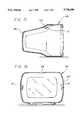
- FIG. 15is a side view of the piezoelectric speaker of the present invention in a computer monitor application
- FIG. 16is a front view of the piezoelectric speaker of the present invention in an alternative embodiment of a computer monitor application
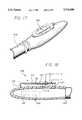
- FIG. 17is a perspective view of the piezoelectric speaker of the present invention in a pen application
- FIG. 18is a cross-sectional side view of the piezoelectric speaker of FIG. 17.
- FIG. 19is a schematic of the secondary winding of the piezoelectric speaker of the present invention.
- the piezoelectric speakercomprises a rigid structure 12, a case 14, a bender 16 disposed within the case and a wave guide mechanism 18 mounted to both the rigid structure 12 and the case 14 and serving to preferably rigidly interconnect the rigid structure and the case.
- the bender 16may be referred to as a piezodriver.
- the case 14further comprises a base portion 20 and a top portion 22.
- the base portion 20is preferable fabricated from a punchboard or other acoustically sound material.
- the top portion 22is preferably fabricated from a manila or other flexible material.
- the bender 16preferably utilizes a piezoelectric wafer 24 or piezowafer and may comprise several different structures.
- a unimorph piezoelectric structurethat includes a piezoelectric material wafer bonded to a stiff shim.
- a second alternativeis a bimorph piezoelectric structure.
- the bimorph structuremay include either two piezoelectric wafers bonded together or two piezoelectric wafers having a stiff shim bonded between the two wafers, as best shown in FIG. 4. It should be noted that the piezoelectric material wafers may be replaced by any type of electroactive material that responds to an electric field by developing a strain.
- a third alternativeis a RAINBOWTM wafer. Additionally, another advantage of the present invention is that the piezoelectric structure is easily manufactured because the thickness of the piezoelectric material may be greater than eight mils.
- the case 14may further include an additional layer 26 on the top portion 2.
- the additional layer 26may be comprised of an adhesive type material and provides additional rigidity to the case.
- the encapsulation of the bender in acoustically sound materialsuch as the plastics of keyboards or computer monitors makes the proposed concept very effective in that it utilizes less space, has improved frequency of sound, and has improved sensitivity.
- An encapsulated piezowafercreates stress waves as a reaction to an electrical voltage potential input and transmits acoustic waves through the entire structure surface into air.
- the encapsulationalso provides a high durability to entire package, sustainability to harsh shock and vibrational environments.
- FIGS. 1 and 2Another feature of the present invention shown in FIGS. 1 and 2 is that the vibrational mechanical energy of the piezodriver bender 16 is propagated through the wave guide mechanism 18 into the rigidly attached structure 12. An optimal effect is created when the mechanical impedance of an attached structure is matched with a piezodriver impedance.
- the wave guide mechanism 18features a one point attachment.
- a short bolt, pin or rodis attached in the location of highest vibrational energy, which in the case of RAINBOW, bimorph, or unimorph benders is the geometrical center of the piezoelectric wafer. This feature provides simplicity, compactness and low cost for the design.
- the wave guide 18is preferably comprised of a a rigid material such as a metal rod and is attached to a center portion of the case or bender by an adhesive or other securing means.
- the wave guidemay comprise a nut or bolt.
- An alternative embodiment of the wave guide 18is shown in FIG. 2.
- the wave guide 18is constructed of a a first nut 28, secured to the case 14 and a second nut 30 secured to the rigid structure 12.
- a bolt 32serves to interconnect the two nuts 28, 30.
- the piezoelectric speaker embodiment shown in FIG. 1utilizes a RAINBOW wafer 34 having a dome structure.
- the wafer 34defines a first surface 36 and a second surface 38.
- a first electrode 40is mounted adjacent the first surface 36 and a second electrode 42 is mounted adjacent the second surface 38.
- Electric leads 44are attached to the electrodes.
- the RAINBOW waferhas an initial unbiased height. The wafer is preferably preloaded by being compressed to approximately 50% of the initial unbiased height before it is disposed within the case.
- the benders used in the piezoelectric speakersare preferably preloaded.
- the preload of the piezoelectric bender waferscan be achieved in various ways.
- a RAINBOW waferis preferably preloaded by a simple biased deformation of a dome structure to 50% of its height.
- the bimorph or unimorph bendersmay be preloaded by being pressed fit.
- the bimorph or unimorph bendersmay be preloaded with a spring, such as the flat curved disk type.
- the benderincludes a shim 48, a first piezoelectric material wafer 50 and a second piezoelectric material wafer 52.
- the shimdefines a first surface 54 and a second surface 56.
- the first piezoelectric material waferis bonded to the first surface of the shim and the second piezoelectric material wafer is bonded to the second surface of the shim.
- the shim 48is preferably fabricated from a steel or brass material.
- the leads 44connect the piezoelectric material wafers to an electrical audio signal.
- a first piezoelectric material waferis bonded to a first surface of a shim.
- the piezoelectric material wafersare bonded to the shim such that the surface of the shim is in contact with the electrodes of the piezoelectric material wafer.
- the wave guide in both the unimorph and bimorph embodimentsis secured to the center of the wafer.
- the piezoelectric speakeris shown utilizing a computer keyboard 58 as the rigid structure.
- the piezoelectric speaker 10is preferably attached to a plastic housing 60 of the computer keyboard, where space is available.
- the piezoelectric speaker 10is attached to the molded keyboard housing 60 and the electrical leads 44 are connected to an electrical audio source.
- FIG. 6a piezoelectric speaker utilizing a bicycle helmet 62 as the rigid structure is shown.
- the piezoelectric speakers 10are built in a foam layer 68 that is disposed inside an outer shell 70 of the bicycle helmet.
- This embodimentutilizes curved disk type springs 72 to facilitate the preload for better acoustical coupling.
- FIGS. 9 and 10another embodiment of the piezoelectric speaker utilizing the bicycle helmet 62 as the rigid structure is shown.
- the speaker 10is attached by two shims 64 made out of sheet metal.
- Two nuts 66function as the wave guide to the foam structure.
- An advantage of this embodiment of the piezoelectric speakeris that the entire package may be molded into a foam layer 68 within the bicycle helmet 62. In this manner, a bicyclist does not require any additional power sources attached to other parts of the body or carried by hand. Additionally, the piezoelectric speakers are molded above the bicyclist's ear, therefore preventing any obstruction to the bicyclists ears. Shims 64 may also function as an enclosure of the piezospeakers 10 as shown in FIG. 8.
- FIG. 9demonstrates how entire circuit is molded into the foam lining 68.
- a battery 74, a converter 76, and a voltage amplifier 78are molded into the foam and two speakers 10 for stereo sound are molded above a bicyclist earhole 80.
- the rigid structureis a conventional loudspeaker cone 82.
- the coneis attached to the bender 16 through an intermediate plate 84 and a waveguide 85.
- the plate 84may be fabricated from a punchboard or other acoustically sound material.
- FIG. 12an embodiment of the piezoelectric speaker is shown wherein the rigid structure is an office desk 86.
- the speaker 10is secured to the a top surface 88 of the desk 86, such that the entire top surface 88 of the desk functions as a speaker.
- FIGS. 13 and 14an embodiment of the piezoelectric speaker is shown wherein the rigid structure is a drywall material 90.
- This embodimentallows the present invention to be used as a home entertainment system.
- the speaker 10is secured to the housing frame 92 or drywall 90 within the frame.
- the speakersmay be used for music or paging purposes.
- a feature of embodiment shown in FIG. 13is the use of a third speaker 94 and the utilization a tuned circuit with the piezoelectric speakers 10.
- the tuned circuitallows accentuation of any desired frequency from the piezoelectric speaker by combining two, three or four speakers. As a result, higher fidelity sound can be obtained.
- the rigid structureis a computer monitor 96.
- the piezoelectric speaker 10is secured to an upper wall 100 of a plastic shell 98 of the computer monitor.
- the speakermay be secured to a sidewall 102 of the plastic shell 98 of the computer monitor 96.
- the rigid structureis a pen or pencil 104.
- the speaker 10is preferably secured to a clip 106 of the pen or pencil.
- the bender 16may comprise a bimorph having a shim 110, two wafers 112, and two wave guides 114.
- the electrical leadsare connected internally to an electrical sources 118.
- a power supply 120is also located within the pen or pencil 104.
- a secondary winding 120 of transformer 122is shown that can be tuned to a desired frequency by selecting inductance L2 as a function of capacitance C of the piezoelectric speaker.
Landscapes
- Physics & Mathematics (AREA)
- Engineering & Computer Science (AREA)
- Acoustics & Sound (AREA)
- Signal Processing (AREA)
- Piezo-Electric Transducers For Audible Bands (AREA)
Abstract
Description
S=sT+dE (3)
S=dE (4)
-sT=dE (5)
x(n/a)+y(n/b)=1
Claims (2)
Priority Applications (3)
| Application Number | Priority Date | Filing Date | Title |
|---|---|---|---|
| US08/577,279US5736808A (en) | 1995-12-22 | 1995-12-22 | Piezoelectric speaker |
| US09/056,394US6396197B1 (en) | 1995-12-22 | 1998-04-06 | Piezoelectric speaker |
| US10/155,580US6674219B1 (en) | 1995-12-22 | 2002-05-24 | Piezoelectric speaker |
Applications Claiming Priority (1)
| Application Number | Priority Date | Filing Date | Title |
|---|---|---|---|
| US08/577,279US5736808A (en) | 1995-12-22 | 1995-12-22 | Piezoelectric speaker |
Related Child Applications (1)
| Application Number | Title | Priority Date | Filing Date |
|---|---|---|---|
| US09/056,394Continuation-In-PartUS6396197B1 (en) | 1995-12-22 | 1998-04-06 | Piezoelectric speaker |
Publications (1)
| Publication Number | Publication Date |
|---|---|
| US5736808Atrue US5736808A (en) | 1998-04-07 |
Family
ID=24308033
Family Applications (1)
| Application Number | Title | Priority Date | Filing Date |
|---|---|---|---|
| US08/577,279Expired - Fee RelatedUS5736808A (en) | 1995-12-22 | 1995-12-22 | Piezoelectric speaker |
Country Status (1)
| Country | Link |
|---|---|
| US (1) | US5736808A (en) |
Cited By (33)
| Publication number | Priority date | Publication date | Assignee | Title |
|---|---|---|---|---|
| US6137890A (en)* | 1997-05-06 | 2000-10-24 | Compaq Computer Corporation | Lumped parameter resonator of a piezoelectric speaker |
| US6198206B1 (en)* | 1998-03-20 | 2001-03-06 | Active Control Experts, Inc. | Inertial/audio unit and construction |
| US6222304B1 (en)* | 1999-07-28 | 2001-04-24 | The Charles Stark Draper Laboratory | Micro-shell transducer |
| US20010033669A1 (en)* | 2000-01-24 | 2001-10-25 | Graham Bank | Resonant element transducer |
| US6342749B1 (en)* | 1999-04-29 | 2002-01-29 | New Transducers Limited | Vibration exciter |
| US6396197B1 (en)* | 1995-12-22 | 2002-05-28 | Speaker Acquisition Sub, A Cayman Island Corporation | Piezoelectric speaker |
| US20030059069A1 (en)* | 2000-01-27 | 2003-03-27 | New Transducers Limited | Loudspeaker |
| US6639988B2 (en) | 2000-08-31 | 2003-10-28 | Delphi Technologies, Inc. | Piezo integrated flat speakers for automotive interior panels |
| US6657364B1 (en)* | 1999-10-01 | 2003-12-02 | Ngk Insulators, Ltd. | Piezoelectric/electrostrictive device |
| US20040189151A1 (en)* | 2000-01-07 | 2004-09-30 | Lewis Athanas | Mechanical-to-acoustical transformer and multi-media flat film speaker |
| US6862358B1 (en)* | 1999-10-08 | 2005-03-01 | Honda Giken Kogyo Kabushiki Kaisha | Piezo-film speaker and speaker built-in helmet using the same |
| GB2405550A (en)* | 2001-06-15 | 2005-03-02 | 1 Ltd | Loudspeaker mechanism |
| US20050279566A1 (en)* | 2002-09-17 | 2005-12-22 | Anthony Hooley | Loudspeaker |
| US7130436B1 (en) | 1999-09-09 | 2006-10-31 | Honda Giken Kogyo Kabushiki Kaisha | Helmet with built-in speaker system and speaker system for helmet |
| US20060269087A1 (en)* | 2005-05-31 | 2006-11-30 | Johnson Kevin M | Diaphragm Membrane And Supporting Structure Responsive To Environmental Conditions |
| US20080018203A1 (en)* | 2006-07-20 | 2008-01-24 | Hosiden Corporation | Piezoelectric electroacoustic transducing device |
| US20100061584A1 (en)* | 2008-09-05 | 2010-03-11 | Gloria Lin | Compact Housing for Portable Electronic Device with Internal Speaker |
| US20100061577A1 (en)* | 2008-09-05 | 2010-03-11 | Kyle Yeates | Electromagnetic Interference Shields with Piezos |
| US20100224437A1 (en)* | 2009-03-06 | 2010-09-09 | Emo Labs, Inc. | Optically Clear Diaphragm For An Acoustic Transducer And Method For Making Same |
| US20100246143A1 (en)* | 2009-03-26 | 2010-09-30 | Richard Hung Minh Dinh | Electromagnetic Interference Shielding for Compact Electronic Devices |
| US20100322455A1 (en)* | 2007-11-21 | 2010-12-23 | Emo Labs, Inc. | Wireless loudspeaker |
| US20110044476A1 (en)* | 2009-08-14 | 2011-02-24 | Emo Labs, Inc. | System to generate electrical signals for a loudspeaker |
| US20140079255A1 (en)* | 2011-05-17 | 2014-03-20 | Murata Manufacturing Co., Ltd. | Plane-Type Speaker and AV Apparatus |
| JP2014112891A (en)* | 2012-02-28 | 2014-06-19 | Kyocera Corp | Piezoelectric vibration element, piezoelectric vibration device, and portable terminal |
| USD733678S1 (en) | 2013-12-27 | 2015-07-07 | Emo Labs, Inc. | Audio speaker |
| US9094743B2 (en) | 2013-03-15 | 2015-07-28 | Emo Labs, Inc. | Acoustic transducers |
| USD741835S1 (en) | 2013-12-27 | 2015-10-27 | Emo Labs, Inc. | Speaker |
| USD748072S1 (en) | 2014-03-14 | 2016-01-26 | Emo Labs, Inc. | Sound bar audio speaker |
| US9387897B2 (en) | 2011-02-01 | 2016-07-12 | ORP Industries LLC | Smart horn system and method |
| US10241223B2 (en) | 2015-11-19 | 2019-03-26 | Halliburton Energy Services, Inc. | Downhole piezoelectric acoustic transducer |
| US20190328360A1 (en)* | 2018-04-30 | 2019-10-31 | Vermon S.A. | Ultrasound transducer |
| CN111711899A (en)* | 2020-06-22 | 2020-09-25 | 武汉华星光电技术有限公司 | Display panel |
| USD922693S1 (en)* | 2020-05-22 | 2021-06-15 | Gentex Corporation | Mounting rail node |
Citations (13)
| Publication number | Priority date | Publication date | Assignee | Title |
|---|---|---|---|---|
| US1526319A (en)* | 1924-01-08 | 1925-02-17 | Westinghouse Electric & Mfg Co | Piezo-electric loud speaker |
| US2386279A (en)* | 1942-07-21 | 1945-10-09 | Raymond W Tibbetts | Piezoelectric device |
| US3109111A (en)* | 1961-10-30 | 1963-10-29 | Euphonics Corp | Ultra-sonic microphone |
| US3268855A (en)* | 1963-03-19 | 1966-08-23 | Electro Voice | Ultrasonic microphone |
| US3278695A (en)* | 1963-03-21 | 1966-10-11 | Astatic Corp | Construction of earphones and microphones |
| US3560771A (en)* | 1966-07-15 | 1971-02-02 | Hb Eng Corp | Acoustically active resonator |
| US4045695A (en)* | 1974-07-15 | 1977-08-30 | Pioneer Electronic Corporation | Piezoelectric electro-acoustic transducer |
| US4283605A (en)* | 1978-04-07 | 1981-08-11 | Matsushita Electric Industrial Co., Ltd. | Piezoelectric speaker |
| US4379211A (en)* | 1980-10-14 | 1983-04-05 | Telephonics Corporation | Arcuately tensioned piezoelectric diaphragm microphone |
| US4607186A (en)* | 1981-11-17 | 1986-08-19 | Matsushita Electric Industrial Co. Ltd. | Ultrasonic transducer with a piezoelectric element |
| US4696045A (en)* | 1985-06-04 | 1987-09-22 | Acr Electronics | Ear microphone |
| US5514927A (en)* | 1994-02-28 | 1996-05-07 | Motorola, Inc. | Piezoelectric audio transducer |
| US5541467A (en)* | 1992-07-03 | 1996-07-30 | Murata Manufacturing Co., Ltd. | Vibrating unit |
- 1995
- 1995-12-22USUS08/577,279patent/US5736808A/ennot_activeExpired - Fee Related
Patent Citations (13)
| Publication number | Priority date | Publication date | Assignee | Title |
|---|---|---|---|---|
| US1526319A (en)* | 1924-01-08 | 1925-02-17 | Westinghouse Electric & Mfg Co | Piezo-electric loud speaker |
| US2386279A (en)* | 1942-07-21 | 1945-10-09 | Raymond W Tibbetts | Piezoelectric device |
| US3109111A (en)* | 1961-10-30 | 1963-10-29 | Euphonics Corp | Ultra-sonic microphone |
| US3268855A (en)* | 1963-03-19 | 1966-08-23 | Electro Voice | Ultrasonic microphone |
| US3278695A (en)* | 1963-03-21 | 1966-10-11 | Astatic Corp | Construction of earphones and microphones |
| US3560771A (en)* | 1966-07-15 | 1971-02-02 | Hb Eng Corp | Acoustically active resonator |
| US4045695A (en)* | 1974-07-15 | 1977-08-30 | Pioneer Electronic Corporation | Piezoelectric electro-acoustic transducer |
| US4283605A (en)* | 1978-04-07 | 1981-08-11 | Matsushita Electric Industrial Co., Ltd. | Piezoelectric speaker |
| US4379211A (en)* | 1980-10-14 | 1983-04-05 | Telephonics Corporation | Arcuately tensioned piezoelectric diaphragm microphone |
| US4607186A (en)* | 1981-11-17 | 1986-08-19 | Matsushita Electric Industrial Co. Ltd. | Ultrasonic transducer with a piezoelectric element |
| US4696045A (en)* | 1985-06-04 | 1987-09-22 | Acr Electronics | Ear microphone |
| US5541467A (en)* | 1992-07-03 | 1996-07-30 | Murata Manufacturing Co., Ltd. | Vibrating unit |
| US5514927A (en)* | 1994-02-28 | 1996-05-07 | Motorola, Inc. | Piezoelectric audio transducer |
Cited By (60)
| Publication number | Priority date | Publication date | Assignee | Title |
|---|---|---|---|---|
| US6396197B1 (en)* | 1995-12-22 | 2002-05-28 | Speaker Acquisition Sub, A Cayman Island Corporation | Piezoelectric speaker |
| US6674219B1 (en) | 1995-12-22 | 2004-01-06 | Speaker Acquisition Sub | Piezoelectric speaker |
| US6137890A (en)* | 1997-05-06 | 2000-10-24 | Compaq Computer Corporation | Lumped parameter resonator of a piezoelectric speaker |
| US6376967B2 (en) | 1998-03-20 | 2002-04-23 | Active Control Experts, Inc. | Inertial/audio unit and construction |
| US6198206B1 (en)* | 1998-03-20 | 2001-03-06 | Active Control Experts, Inc. | Inertial/audio unit and construction |
| US6342749B1 (en)* | 1999-04-29 | 2002-01-29 | New Transducers Limited | Vibration exciter |
| US6222304B1 (en)* | 1999-07-28 | 2001-04-24 | The Charles Stark Draper Laboratory | Micro-shell transducer |
| DE10043913B4 (en)* | 1999-09-09 | 2012-03-22 | Honda Giken Kogyo K.K. | Helmet with built-in speaker system |
| US7130436B1 (en) | 1999-09-09 | 2006-10-31 | Honda Giken Kogyo Kabushiki Kaisha | Helmet with built-in speaker system and speaker system for helmet |
| US6657364B1 (en)* | 1999-10-01 | 2003-12-02 | Ngk Insulators, Ltd. | Piezoelectric/electrostrictive device |
| US6862358B1 (en)* | 1999-10-08 | 2005-03-01 | Honda Giken Kogyo Kabushiki Kaisha | Piezo-film speaker and speaker built-in helmet using the same |
| DE10049492B4 (en)* | 1999-10-08 | 2011-12-15 | Honda Giken Kogyo K.K. | Helmet with built-in piezo film speaker |
| US20040189151A1 (en)* | 2000-01-07 | 2004-09-30 | Lewis Athanas | Mechanical-to-acoustical transformer and multi-media flat film speaker |
| US7038356B2 (en) | 2000-01-07 | 2006-05-02 | Unison Products, Inc. | Mechanical-to-acoustical transformer and multi-media flat film speaker |
| US20010033669A1 (en)* | 2000-01-24 | 2001-10-25 | Graham Bank | Resonant element transducer |
| US7684576B2 (en) | 2000-01-24 | 2010-03-23 | New Transducers Limited | Resonant element transducer |
| US7149318B2 (en) | 2000-01-24 | 2006-12-12 | New Transducers Limited | Resonant element transducer |
| US20070086616A1 (en)* | 2000-01-24 | 2007-04-19 | New Transducers Limited | Resonant element transducer |
| US20030059069A1 (en)* | 2000-01-27 | 2003-03-27 | New Transducers Limited | Loudspeaker |
| US7151837B2 (en) | 2000-01-27 | 2006-12-19 | New Transducers Limited | Loudspeaker |
| US6639988B2 (en) | 2000-08-31 | 2003-10-28 | Delphi Technologies, Inc. | Piezo integrated flat speakers for automotive interior panels |
| GB2405550A (en)* | 2001-06-15 | 2005-03-02 | 1 Ltd | Loudspeaker mechanism |
| US20050279566A1 (en)* | 2002-09-17 | 2005-12-22 | Anthony Hooley | Loudspeaker |
| US20080273720A1 (en)* | 2005-05-31 | 2008-11-06 | Johnson Kevin M | Optimized piezo design for a mechanical-to-acoustical transducer |
| US20060269087A1 (en)* | 2005-05-31 | 2006-11-30 | Johnson Kevin M | Diaphragm Membrane And Supporting Structure Responsive To Environmental Conditions |
| US7884529B2 (en) | 2005-05-31 | 2011-02-08 | Emo Labs, Inc. | Diaphragm membrane and supporting structure responsive to environmental conditions |
| US7629730B2 (en)* | 2006-07-20 | 2009-12-08 | Hosiden Corporation | Piezoelectric electroacoustic transducing device |
| US20080018203A1 (en)* | 2006-07-20 | 2008-01-24 | Hosiden Corporation | Piezoelectric electroacoustic transducing device |
| US20100322455A1 (en)* | 2007-11-21 | 2010-12-23 | Emo Labs, Inc. | Wireless loudspeaker |
| US8494207B2 (en) | 2008-09-05 | 2013-07-23 | Apple Inc. | Compact housing for portable electronic device with internal speaker |
| US20100061577A1 (en)* | 2008-09-05 | 2010-03-11 | Kyle Yeates | Electromagnetic Interference Shields with Piezos |
| US8126170B2 (en) | 2008-09-05 | 2012-02-28 | Apple Inc. | Electromagnetic interference shields with piezos |
| US20100061584A1 (en)* | 2008-09-05 | 2010-03-11 | Gloria Lin | Compact Housing for Portable Electronic Device with Internal Speaker |
| US8265329B2 (en) | 2008-09-05 | 2012-09-11 | Apple Inc. | Compact housing for portable electronic device with internal speaker |
| US8457333B2 (en) | 2008-09-05 | 2013-06-04 | Apple Inc. | Electromagnetic interference shields with piezos |
| US20100224437A1 (en)* | 2009-03-06 | 2010-09-09 | Emo Labs, Inc. | Optically Clear Diaphragm For An Acoustic Transducer And Method For Making Same |
| US8189851B2 (en) | 2009-03-06 | 2012-05-29 | Emo Labs, Inc. | Optically clear diaphragm for an acoustic transducer and method for making same |
| US9232316B2 (en) | 2009-03-06 | 2016-01-05 | Emo Labs, Inc. | Optically clear diaphragm for an acoustic transducer and method for making same |
| US8798310B2 (en) | 2009-03-06 | 2014-08-05 | Emo Labs, Inc. | Optically clear diaphragm for an acoustic transducer and method for making same |
| US20100246143A1 (en)* | 2009-03-26 | 2010-09-30 | Richard Hung Minh Dinh | Electromagnetic Interference Shielding for Compact Electronic Devices |
| US20110044476A1 (en)* | 2009-08-14 | 2011-02-24 | Emo Labs, Inc. | System to generate electrical signals for a loudspeaker |
| US9387897B2 (en) | 2011-02-01 | 2016-07-12 | ORP Industries LLC | Smart horn system and method |
| US9332353B2 (en)* | 2011-05-17 | 2016-05-03 | Murata Manufacturing Co., Ltd. | Plane-type speaker and AV apparatus |
| US20150131823A1 (en)* | 2011-05-17 | 2015-05-14 | Murata Manufacturing Co., Ltd. | Plane-Type Speaker and AV Apparatus |
| US20140079255A1 (en)* | 2011-05-17 | 2014-03-20 | Murata Manufacturing Co., Ltd. | Plane-Type Speaker and AV Apparatus |
| US9363607B2 (en)* | 2011-05-17 | 2016-06-07 | Murata Manufacturing Co., Ltd. | Plane-type speaker and AV apparatus |
| JP2014112891A (en)* | 2012-02-28 | 2014-06-19 | Kyocera Corp | Piezoelectric vibration element, piezoelectric vibration device, and portable terminal |
| US9226078B2 (en) | 2013-03-15 | 2015-12-29 | Emo Labs, Inc. | Acoustic transducers |
| US9100752B2 (en) | 2013-03-15 | 2015-08-04 | Emo Labs, Inc. | Acoustic transducers with bend limiting member |
| US9094743B2 (en) | 2013-03-15 | 2015-07-28 | Emo Labs, Inc. | Acoustic transducers |
| USD733678S1 (en) | 2013-12-27 | 2015-07-07 | Emo Labs, Inc. | Audio speaker |
| USD741835S1 (en) | 2013-12-27 | 2015-10-27 | Emo Labs, Inc. | Speaker |
| USD748072S1 (en) | 2014-03-14 | 2016-01-26 | Emo Labs, Inc. | Sound bar audio speaker |
| US10241223B2 (en) | 2015-11-19 | 2019-03-26 | Halliburton Energy Services, Inc. | Downhole piezoelectric acoustic transducer |
| US20190328360A1 (en)* | 2018-04-30 | 2019-10-31 | Vermon S.A. | Ultrasound transducer |
| USD922693S1 (en)* | 2020-05-22 | 2021-06-15 | Gentex Corporation | Mounting rail node |
| USD955661S1 (en) | 2020-05-22 | 2022-06-21 | Gentex Corporation | Mounting rail |
| USD974670S1 (en) | 2020-05-22 | 2023-01-03 | Gentex Corporation | Helmet accessory mounting system |
| USD1003526S1 (en) | 2020-05-22 | 2023-10-31 | Gentex Corporation | Power supply attachment surface node |
| CN111711899A (en)* | 2020-06-22 | 2020-09-25 | 武汉华星光电技术有限公司 | Display panel |
Similar Documents
| Publication | Publication Date | Title |
|---|---|---|
| US5736808A (en) | Piezoelectric speaker | |
| US6674219B1 (en) | Piezoelectric speaker | |
| EP1763283B1 (en) | Piezoelectric device for generating acoustic signals | |
| US5780958A (en) | Piezoelectric vibrating device | |
| US6653762B2 (en) | Piezoelectric type electric acoustic converter | |
| US5856956A (en) | Piezoelectric acoustic transducer | |
| CN110047392B (en) | Display device | |
| US6438242B1 (en) | Acoustic transducer panel | |
| EP1576851B1 (en) | Acoustic actuator | |
| KR100811286B1 (en) | Piezoelectric vibrator for regenerating sound, and piezoelectric panel speaker and piezoelectric earphone having the same | |
| JP2002505822A (en) | Loudspeaker assembly | |
| US12192702B2 (en) | MEMS speaker | |
| CN110957415A (en) | Composite piezoelectric actuator | |
| JP2882346B2 (en) | Piezoelectric earphone | |
| JP5927944B2 (en) | Piezoelectric sounding device | |
| KR101367453B1 (en) | Flat pannel speaker having damper film | |
| WO2006025138A1 (en) | Piezoelectric electroacoustic transducer | |
| KR100729152B1 (en) | Piezoelectric Vibration Device for Piezo Flat Plate Speaker | |
| KR20060097839A (en) | Piezoelectric vibrator vibrating on both sides and piezoelectric flat panel speaker using the same | |
| JPH06113397A (en) | Dual-drive speaker provided with diffusion resonance attenuation | |
| JP4688687B2 (en) | Piezoelectric vibration unit and panel speaker | |
| KR102760387B1 (en) | A Ultrasonic Transducer Assembly | |
| US11968507B2 (en) | Speaker having first diaphragm, second diaphragm with different stiffness from first diaphragm, and driver located in through hole of first diaphragm | |
| JP3924777B2 (en) | Flat speaker | |
| KR102172538B1 (en) | Nonflammables Multy-layer Fevice Piezo Electricity Seaker |
Legal Events
| Date | Code | Title | Description |
|---|---|---|---|
| AS | Assignment | Owner name:AURA SYSTEMS, INC., CALIFORNIA Free format text:ASSIGNMENT OF ASSIGNORS INTEREST;ASSIGNORS:SZILAGYI, ANDREI;STRUGACH, MICHAEL;REEL/FRAME:007944/0580 Effective date:19960318 | |
| AS | Assignment | Owner name:REGALTRONIC LTD., HONG KONG Free format text:SECURITY AGREEMENT;ASSIGNOR:AURA SYSTEMS, INC.;REEL/FRAME:010043/0318 Effective date:19990606 | |
| AS | Assignment | Owner name:SPEAKER ACQUISITION SUB, A CAYMAN ISLAND CORPORATI Free format text:OPTION;ASSIGNOR:AURA SYSTEMS, INC.;REEL/FRAME:010133/0183 Effective date:19990715 | |
| AS | Assignment | Owner name:SPEAKER ACQUISITION SUB, A CAYMAN ISLAND CORPORATI Free format text:ASSIGNMENT OF ASSIGNORS INTEREST;ASSIGNOR:AURA SYSTEMS, INC.;REEL/FRAME:010589/0535 Effective date:19990715 | |
| FEPP | Fee payment procedure | Free format text:PAYOR NUMBER ASSIGNED (ORIGINAL EVENT CODE: ASPN); ENTITY STATUS OF PATENT OWNER: SMALL ENTITY | |
| FPAY | Fee payment | Year of fee payment:4 | |
| REMI | Maintenance fee reminder mailed | ||
| REIN | Reinstatement after maintenance fee payment confirmed | ||
| FP | Lapsed due to failure to pay maintenance fee | Effective date:20060407 | |
| FEPP | Fee payment procedure | Free format text:PETITION RELATED TO MAINTENANCE FEES GRANTED (ORIGINAL EVENT CODE: PMFG); ENTITY STATUS OF PATENT OWNER: SMALL ENTITY Free format text:PAT HOLDER CLAIMS SMALL ENTITY STATUS, ENTITY STATUS SET TO SMALL (ORIGINAL EVENT CODE: LTOS); ENTITY STATUS OF PATENT OWNER: SMALL ENTITY Free format text:PETITION RELATED TO MAINTENANCE FEES FILED (ORIGINAL EVENT CODE: PMFP); ENTITY STATUS OF PATENT OWNER: SMALL ENTITY | |
| PRDP | Patent reinstated due to the acceptance of a late maintenance fee | Effective date:20070207 | |
| FPAY | Fee payment | Year of fee payment:8 | |
| SULP | Surcharge for late payment | ||
| AS | Assignment | Owner name:AURASOUND, INC., CALIFORNIA Free format text:ASSIGNMENT OF ASSIGNORS INTEREST;ASSIGNOR:SPEAK ACQUISITION SUB;REEL/FRAME:020783/0959 Effective date:20070209 | |
| REMI | Maintenance fee reminder mailed | ||
| LAPS | Lapse for failure to pay maintenance fees | ||
| STCH | Information on status: patent discontinuation | Free format text:PATENT EXPIRED DUE TO NONPAYMENT OF MAINTENANCE FEES UNDER 37 CFR 1.362 | |
| FP | Lapsed due to failure to pay maintenance fee | Effective date:20100407 | |
| AS | Assignment | Owner name:GGEC AMERICA, INC., CALIFORNIA Free format text:ASSIGNMENT OF ASSIGNORS INTEREST;ASSIGNOR:AURASOUND, INC.;REEL/FRAME:030666/0228 Effective date:20130608 |