US5736168A - Blow mold with replaceable inserts - Google Patents
Blow mold with replaceable insertsDownload PDFInfo
- Publication number
- US5736168A US5736168AUS08/715,005US71500596AUS5736168AUS 5736168 AUS5736168 AUS 5736168AUS 71500596 AUS71500596 AUS 71500596AUS 5736168 AUS5736168 AUS 5736168A
- Authority
- US
- United States
- Prior art keywords
- insert
- mold
- combination according
- mold body
- sections
- Prior art date
- Legal status (The legal status is an assumption and is not a legal conclusion. Google has not performed a legal analysis and makes no representation as to the accuracy of the status listed.)
- Expired - Lifetime
Links
Images


Classifications
- B—PERFORMING OPERATIONS; TRANSPORTING
- B29—WORKING OF PLASTICS; WORKING OF SUBSTANCES IN A PLASTIC STATE IN GENERAL
- B29C—SHAPING OR JOINING OF PLASTICS; SHAPING OF MATERIAL IN A PLASTIC STATE, NOT OTHERWISE PROVIDED FOR; AFTER-TREATMENT OF THE SHAPED PRODUCTS, e.g. REPAIRING
- B29C49/00—Blow-moulding, i.e. blowing a preform or parison to a desired shape within a mould; Apparatus therefor
- B29C49/42—Component parts, details or accessories; Auxiliary operations
- B29C49/48—Moulds
- B29C49/48185—Moulds with more than one separate mould cavity
- B—PERFORMING OPERATIONS; TRANSPORTING
- B29—WORKING OF PLASTICS; WORKING OF SUBSTANCES IN A PLASTIC STATE IN GENERAL
- B29C—SHAPING OR JOINING OF PLASTICS; SHAPING OF MATERIAL IN A PLASTIC STATE, NOT OTHERWISE PROVIDED FOR; AFTER-TREATMENT OF THE SHAPED PRODUCTS, e.g. REPAIRING
- B29C33/00—Moulds or cores; Details thereof or accessories therefor
- B29C33/30—Mounting, exchanging or centering
- B29C33/306—Exchangeable mould parts, e.g. cassette moulds, mould inserts
- B—PERFORMING OPERATIONS; TRANSPORTING
- B29—WORKING OF PLASTICS; WORKING OF SUBSTANCES IN A PLASTIC STATE IN GENERAL
- B29C—SHAPING OR JOINING OF PLASTICS; SHAPING OF MATERIAL IN A PLASTIC STATE, NOT OTHERWISE PROVIDED FOR; AFTER-TREATMENT OF THE SHAPED PRODUCTS, e.g. REPAIRING
- B29C49/00—Blow-moulding, i.e. blowing a preform or parison to a desired shape within a mould; Apparatus therefor
- B29C49/42—Component parts, details or accessories; Auxiliary operations
- B29C49/48—Moulds
- B29C49/52—Moulds having decorating or printing means
Definitions
- PET containersare made of bi-axially oriented thermoplastic material.
- PET containersare readily molded by orientation blowing to produce transparent thin walled containers having high impact strength and excellent stiffness. This is done with a high molding accuracy.
- PET containersalso are substantially heat resistant and are produced by the bi-axial-orientation blow-molding process, in which a parison is oriented both laterally and longitudinally in a temperature range which is suitable for the orientation.
- Bi-axially oriented blow-molded containershave greater stiffness and strength, as well as improved gas barrier properties and transparency.
- PET containersare replacing prior art glass containers in many applications.
- a primary advantage of PET containersis the lightweight thin walled characteristic, which substantially reduces the bulk of the combination of container and product and the weight of the container/product for shipping and handling purposes.
- Another obvious advantage over glass containersis the high impact resistance of PET containers; so that losses during handling and shipping are significantly reduced.
- FIGS. 1 and 2Another U.S. Pat. No No. 3,380,121 to Chittenden discloses a cylindrical mold in which replaceable inserts are used on both of the mold halves. The manner in which these inserts are held in place and changed is shown most clearly in FIGS. 1 and 2.
- the hemi-cylindrical insertsare configured to fit against the mold interior; and they are clamped in place by vertical clamping strips on each of the mold halves. These strips are screwed into the mold halves to secure them to the mold half and in turn clamp the inserts in place. Full access to the interior of the mold is required in order to secure the inserts; so that the mold must be fully opened to expose completely each of the two halves so that the inserts can be changed.
- blow mold assemblywhich overcomes the disadvantages of the prior art, and which permits a simple lock system to enable fast and easy change of inserts in the mold.
- a mold for use in producing blow molded thermoplastic containerscomprises a multi-section mold body.
- This mold bodyforms a cavity in the closed position in the shape of the container to be produced by the mold.
- a recessis formed in the inner surface of at least one of the sections of the mold cavity.
- Removable inserts dimensioned to fit into the recessare designed to be placed in it; and the inserts are releasably secured in the recess in the section of the mold body without requiring disassembly of the mold.
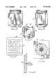
- FIG. 1is a top view of a preferred embodiment of the invention
- FIG. 2is a cross-sectional view taken along the line 2--2 of FIG. 1;
- FIG. 3is a top view of a portion of the bottom assembly shown in FIG. 2;
- FIG. 4is a side view of a container made in the mold assembly shown in FIGS. 1 to 3;
- FIG. 5is a different side view of the container shown in FIG. 4;
- FIG. 6is a bottom view of the container shown in FIGS. 4 and 5;
- FIGS. 7 and 8are front views of inserts used in the mold assembly of FIGS. 1 and 2;
- FIG. 9is a cross-sectional view taken along the line 9--9 of FIG. 8;
- FIG. 10is an enlarged partially cut-away top view of a portion of the embodiment shown in FIG. 1, illustrating details of the invention.
- FIG. 11is a cross-sectional view taken along the line 11--11 of FIG. 10.
- FIG. 1is a top view of a multiple cavity mold made in accordance with a preferred embodiment of the invention.
- the moldconsists of two symmetrical halves 10 and 12, which form a parting line for the mold horizontally across the center of the assembly, as illustrated in FIG. 1.
- the sections 10 and 12are mounted in a mold machine for movement toward and away from one another.
- the mold which is shown in the various figures of the drawingis used in conjunction with a standard blow-mold molding apparatus; and conventional techniques which are used for forming blow molded PET containers are employed in conjunction with the specific mold structures shown in the various figures of the drawing.
- the standard molding machine featuresare not illustrated in the drawings, since these features do not constitute any part of the invention, and since blow molding apparatus is well known.
- FIGS. 1 through 3Each of the separate mold cavities is formed by four different mold sections 14A, 14B, 14C and 14D comprising the four quarters of the mold, as illustrated most clearly in FIG. 1.
- the mold cavityis designed to form a PET container with four large rectangular flat surfaces, interconnected diagonally by four relatively smaller rectangular flat surfaces.
- the container which is formed by the mold shown in FIGS. 1 and 2is illustrated in FIGS. 4 through 6.
- This containercomprises a jar 40 with major flat surfaces 42, 43, 44 and 45, some of which are shown in FIGS. 4 and 5.
- the container 40has a hemispherical concave depression 41 formed in the bottom, also as shown most clearly in FIGS. 4, 5 and 6.
- the container which is to be made in the various cavities of the moldhas an upper open circular top 18 formed by the four quadrants of the sections 14A, 14B, 14C and 14D.
- the sections 14A and 14Binclude surfaces 16 and 17, which are used to form the surfaces 42 and 44, for example, of the container shown in FIGS. 4 through 6.
- a pair of holes 26 and 28are drilled or formed vertically downwardly through the blocks 14A, 14B, 14C and 14D to depths which are shown most clearly in FIG. 11. These vertical holes are located on a line extending radially outwardly from the center of the mold cavity, as is most readily apparent from an examination of FIG. 1.
- the bottom of the mold cavityis closed by the bottom mold assembly comprising a bottom plate 20, to which are attached hollow vertical plastic supply tubes 22 with a center air inlet.
- the top end of the tubes 22are closed with an upper cap 24, which has a hemispherical top in it for producing the concave depression 41 in the bottom of the finished container, as shown in FIGS. 4 through 6.
- This type of structureas illustrated most clearly in FIGS. 2 and 3, is conventional, and is used in conventional blow mold assemblies.
- the internal configuration of the sections 14A, 14B, 14C and 14Dmay be varied to form containers of any desired shape; and the container specifically illustrated in conjunction with all of the figures of this drawing is used only for illustration and is in no way limiting of the container shapes which may be produced by molds incorporating the invention.
- FIGS. 7 through 11illustrate the specific features of replaceable inserts used in conjunction with the mold shown in FIGS. 1 through 3.
- FIGS. 7 and 8are different front or face views of an insert 50, which is used in conjunction with the mold of FIGS. 1 through 3 to form different, "embossed" designs on the surface of a container blow molded in the mold.
- FIG. 7shows a word pattern or word design 56 which may be used. This pattern is a mirror image of the positive pattern which actually will appear on the outside of the container.
- the pattern in FIG. 8is of a design which alternatively may be used instead of a word message, such as the pattern 56 of FIG. 7. It should be noted that the patterns 56 and 58 merely are representative of an infinite variety of patterns which may be employed for customizing the appearance of a container made in the mold of FIGS. 1 through 3.
- FIG. 9is a cross section of the insert shown in FIG. 8, and comprises the insert member 50, which has a thickness designed to fit into and conform with a recess 51 (shown most clearly in FIG. 11) located in the face of the appropriate section 14A, 14B, 14C or 14D of the mold body.
- a dowel pin or rod 52extends at right angles.
- the pin or rod 52is secured to the insert block 50 in any suitable manner, and as shown in FIG. 9, may be set into a tap hole or receptacle. Once the dowel pin 52 is secured in place and the appropriate design is formed on the face of the insert 50, the insert is ready for use in the mold.
- the inserts 50are made of aluminum for use in PET injection molds; although other suitable materials may be employed, which are compatible with the materials of the mold sections 14A, 14B, 14C and 14D and with the temperature ranges encountered in the molding operation.
- the pin 52when an insert 50 is placed in the recess 51 located in the section of the mold body, the pin 52 extends through a corresponding tap hole 53 extending at right angles to the face of the recess 51 in the mold section, such as 14B for example. As shown in FIGS. 10 and 11, the pin 52 extends past the bottom of the hole 28 and into the hole 26 extending a short distance into the hole 26 and located a short distance above the bottom of the hole 26. This is shown most clearly in FIG. 11.
- a set screw 30is rotated in the tapped hole 28 to engage the pin 52 and hold it firmly in place in the hole or channel 53.
- the set screw 30is loosened or removed to relieve the pressure on the pin 52.
- An elongated rod or screwdriverwhich has a smaller outside diameter than the inside diameter of the hole 26, then is inserted downwardly into the hole 26 and is moved to press against the end of the dowel pin 52 to push the insert 50 outwardly into the interior of the cavity formed in the mold section 14B, of which the section lab shown in FIG. 11 is a part.
- the insert 50may be grasped and withdrawn to pull the pin 52 entirely out of the channel 53.
- the insert 50then may be removed from the open top of the mold 18 and replaced with another insert 50 through the open top of the mold 18. In the present example, this is readily accomplished because the width of the insert 50 is selected to be less than the diameter of the top 18 of the mold; and the combined length of the pin 52 and the thickness of the insert 50 also is less than the diameter of the opening in the top of the mold. This permits insertion and replacement of the inserts 50 without requiring any disassembly of the mold 10/12 whatsoever.
Landscapes
- Engineering & Computer Science (AREA)
- Mechanical Engineering (AREA)
- Manufacturing & Machinery (AREA)
- Moulds For Moulding Plastics Or The Like (AREA)
Abstract
Description
Claims (17)
Priority Applications (1)
| Application Number | Priority Date | Filing Date | Title |
|---|---|---|---|
| US08/715,005US5736168A (en) | 1996-09-17 | 1996-09-17 | Blow mold with replaceable inserts |
Applications Claiming Priority (1)
| Application Number | Priority Date | Filing Date | Title |
|---|---|---|---|
| US08/715,005US5736168A (en) | 1996-09-17 | 1996-09-17 | Blow mold with replaceable inserts |
Publications (1)
| Publication Number | Publication Date |
|---|---|
| US5736168Atrue US5736168A (en) | 1998-04-07 |
Family
ID=24872323
Family Applications (1)
| Application Number | Title | Priority Date | Filing Date |
|---|---|---|---|
| US08/715,005Expired - LifetimeUS5736168A (en) | 1996-09-17 | 1996-09-17 | Blow mold with replaceable inserts |
Country Status (1)
| Country | Link |
|---|---|
| US (1) | US5736168A (en) |
Cited By (35)
| Publication number | Priority date | Publication date | Assignee | Title |
|---|---|---|---|---|
| US6299126B1 (en)* | 1999-03-30 | 2001-10-09 | Hughes, Ii Robert H. | Apparatus for changeably forming information on die cast or molded members |
| US6464922B1 (en) | 1999-12-10 | 2002-10-15 | Autotec, Inc. | Insertion device for plastic molding |
| US6659750B1 (en) | 2000-11-01 | 2003-12-09 | Omnimold, Llc | Blow mold with removable inserts |
| US20050013891A1 (en)* | 2003-07-14 | 2005-01-20 | Uniloy Milacron Inc. | Quick release volume control inserts for molding machines |
| US20060073142A1 (en)* | 2004-09-02 | 2006-04-06 | Genentech, Inc. | Anti-Fc-gamma RIIB receptor antibody and uses therefor |
| US20070007696A1 (en)* | 2005-07-08 | 2007-01-11 | Weymouth Russell F Jr | Method and apparatus for injection molding with direct insert thermal control |
| US7204685B1 (en) | 2003-09-08 | 2007-04-17 | Crain Enterprises, Inc. | Modular mold |
| US7241405B1 (en) | 2003-09-08 | 2007-07-10 | Crain Enterprises, Inc. | Method of renewing a mold block |
| US20070286918A1 (en)* | 2004-09-08 | 2007-12-13 | Crain Enterprises, Inc. | Method of renewing a recyclable mold |
| US20080003321A1 (en)* | 2006-01-20 | 2008-01-03 | Kerr George S | Modular mold system for production of product families |
| US20080006456A1 (en)* | 2006-07-07 | 2008-01-10 | Lucas Christopher F | Blow-molded wheels having undulating treads, methods for producing the same, and children's ride-on vehicles including the same |
| US20080036116A1 (en)* | 2005-04-14 | 2008-02-14 | Ivan Lajoie | Mold for Forming a Candle Body Having an Embossed Design |
| US20080048406A1 (en)* | 2006-08-23 | 2008-02-28 | Arendt Albert L | Blow-molded wheels having undercut treads, methods for producing the same, and children's ride-on vehicles including the same |
| US20080311239A1 (en)* | 2007-06-12 | 2008-12-18 | Paul Alan Miller | Apparatus for Blow Molding |
| US7497677B1 (en) | 2003-09-08 | 2009-03-03 | Crain Enterprises, Inc. | Mold having modular submold |
| US20090155400A1 (en)* | 2007-12-17 | 2009-06-18 | Paul Alan Miller | Apparatus for Blow Molding |
| US20090304838A1 (en)* | 2003-07-29 | 2009-12-10 | Ness Inventions, Inc. | Concrete block mold with moveable liner |
| US20090304842A1 (en)* | 2003-07-29 | 2009-12-10 | Ness Inventions, Inc. | Concrete block mold with moveable liner |
| US7641458B2 (en) | 2006-07-31 | 2010-01-05 | Honda Motor Company, Ltd. | Systems for providing a labeling region on a vehicular body panel |
| US20100092598A1 (en)* | 2003-07-29 | 2010-04-15 | Ness Inventions, Inc. | Concrete block mold with moveable liner |
| US20100095502A1 (en)* | 2008-10-16 | 2010-04-22 | The Coca-Cola Company | Method of configuring a production line to mass customize shaped vessels |
| US20100310699A1 (en)* | 2009-06-05 | 2010-12-09 | Ness Inventions, Inc | Block mold having moveable liner |
| DE102010032618A1 (en)* | 2010-07-29 | 2012-02-02 | Fhw-Moulds Gmbh | Blow mold for use in construction kit for manufacturing of containers, particularly canisters, has two tool components, particularly tool halves, which are movable against each other for opening and closing tool |
| US20120040327A1 (en)* | 2010-08-16 | 2012-02-16 | Jones-Zylon Company | System and method for customizing a food tray |
| US20130043622A1 (en)* | 2011-08-19 | 2013-02-21 | Thomas Hoellriegl | Apparatus for shaping plastics material pre-forms into plastics material containers with pressure pads |
| JP2014005068A (en)* | 2012-06-26 | 2014-01-16 | Honda Plus Kk | Plastic bottle and manufacturing method of the same |
| JP2014005069A (en)* | 2012-06-27 | 2014-01-16 | Honda Plus Kk | Plastic bottle and manufacturing method for the same |
| US20140318329A1 (en)* | 2008-08-08 | 2014-10-30 | Gauthier Biomedical, Inc. | Molding Process And Products Formed Thereby |
| US20150040518A1 (en)* | 2013-08-07 | 2015-02-12 | Ardagh Group | Promotional method utilizing variable glass molds |
| US20160009019A1 (en)* | 2013-03-05 | 2016-01-14 | Honda Motor Co., Ltd. | Blow-molding mold |
| US20170144348A1 (en)* | 2015-11-25 | 2017-05-25 | Taiga Coolers, LLC | System and Method for Production of Customized Food and Beverage Coolers |
| CN107599134A (en)* | 2017-09-15 | 2018-01-19 | 泸州广达包装制品有限公司 | LOGO bottle die can arbitrarily be changed |
| US10286591B2 (en)* | 2013-11-28 | 2019-05-14 | Discma Ag | Blow molding mold |
| US11318658B2 (en) | 2019-09-19 | 2022-05-03 | Nike, Inc. | Mold assembly with removable mold tool, bladder for a wearable article, and method of manufacturing the bladder |
| EP4335620A1 (en)* | 2022-09-08 | 2024-03-13 | Krones AG | Device and method for forming plastic preforms into plastic containers |
Citations (14)
| Publication number | Priority date | Publication date | Assignee | Title |
|---|---|---|---|---|
| US132897A (en)* | 1872-11-12 | Improvement in glass-bottle molds | ||
| US170464A (en)* | 1875-11-30 | Improvement in molds for glassware | ||
| US1559394A (en)* | 1923-05-04 | 1925-10-27 | Josiah H Williams | Mold for making glass sign plates |
| US1595773A (en)* | 1926-05-01 | 1926-08-10 | Gillinder & Sons Inc | Glass mold |
| US2601700A (en)* | 1950-06-20 | 1952-07-01 | Plax Corp | Apparatus for molding plastic bottles |
| US3354509A (en)* | 1965-06-01 | 1967-11-28 | Diversified Prod | Barbell mold |
| US3380121A (en)* | 1965-07-30 | 1968-04-30 | American Can Co | Mold with replaceable inserts |
| US3474498A (en)* | 1967-04-05 | 1969-10-28 | Nat Latex Products Co The | Interchangeable indicia-forming device for blow-molded plastic articles |
| US3550197A (en)* | 1964-08-17 | 1970-12-29 | Continental Can Co | Molds for blowing engraved appearing bottles without the use of engraved molds |
| US3734448A (en)* | 1971-04-29 | 1973-05-22 | Freeman Supply Co | Quick change indicia for patterns and the like |
| US3871611A (en)* | 1973-05-07 | 1975-03-18 | Taketa Phyllis | Mold with removable and replaceable core and cavity inserts |
| US4551084A (en)* | 1983-05-25 | 1985-11-05 | Creative Industries, Inc. | Convertible mold |
| US4884961A (en)* | 1985-07-30 | 1989-12-05 | Yoshino Kogyosho Co., Ltd. | Apparatus for forming plastic containers |
| US5560939A (en)* | 1988-04-28 | 1996-10-01 | Aida Engineering, Ltd. | Mold assembly comprising a sliding mold insert adapted for automated insertion and removal |
- 1996
- 1996-09-17USUS08/715,005patent/US5736168A/ennot_activeExpired - Lifetime
Patent Citations (14)
| Publication number | Priority date | Publication date | Assignee | Title |
|---|---|---|---|---|
| US170464A (en)* | 1875-11-30 | Improvement in molds for glassware | ||
| US132897A (en)* | 1872-11-12 | Improvement in glass-bottle molds | ||
| US1559394A (en)* | 1923-05-04 | 1925-10-27 | Josiah H Williams | Mold for making glass sign plates |
| US1595773A (en)* | 1926-05-01 | 1926-08-10 | Gillinder & Sons Inc | Glass mold |
| US2601700A (en)* | 1950-06-20 | 1952-07-01 | Plax Corp | Apparatus for molding plastic bottles |
| US3550197A (en)* | 1964-08-17 | 1970-12-29 | Continental Can Co | Molds for blowing engraved appearing bottles without the use of engraved molds |
| US3354509A (en)* | 1965-06-01 | 1967-11-28 | Diversified Prod | Barbell mold |
| US3380121A (en)* | 1965-07-30 | 1968-04-30 | American Can Co | Mold with replaceable inserts |
| US3474498A (en)* | 1967-04-05 | 1969-10-28 | Nat Latex Products Co The | Interchangeable indicia-forming device for blow-molded plastic articles |
| US3734448A (en)* | 1971-04-29 | 1973-05-22 | Freeman Supply Co | Quick change indicia for patterns and the like |
| US3871611A (en)* | 1973-05-07 | 1975-03-18 | Taketa Phyllis | Mold with removable and replaceable core and cavity inserts |
| US4551084A (en)* | 1983-05-25 | 1985-11-05 | Creative Industries, Inc. | Convertible mold |
| US4884961A (en)* | 1985-07-30 | 1989-12-05 | Yoshino Kogyosho Co., Ltd. | Apparatus for forming plastic containers |
| US5560939A (en)* | 1988-04-28 | 1996-10-01 | Aida Engineering, Ltd. | Mold assembly comprising a sliding mold insert adapted for automated insertion and removal |
Cited By (54)
| Publication number | Priority date | Publication date | Assignee | Title |
|---|---|---|---|---|
| US6299126B1 (en)* | 1999-03-30 | 2001-10-09 | Hughes, Ii Robert H. | Apparatus for changeably forming information on die cast or molded members |
| US6464922B1 (en) | 1999-12-10 | 2002-10-15 | Autotec, Inc. | Insertion device for plastic molding |
| US6659750B1 (en) | 2000-11-01 | 2003-12-09 | Omnimold, Llc | Blow mold with removable inserts |
| US20050013891A1 (en)* | 2003-07-14 | 2005-01-20 | Uniloy Milacron Inc. | Quick release volume control inserts for molding machines |
| US7014446B2 (en)* | 2003-07-14 | 2006-03-21 | Uniloy Milacron Inc. | Quick release volume control inserts for molding machines |
| US8430661B2 (en)* | 2003-07-29 | 2013-04-30 | Ness Inventions, Inc. | Concrete block mold with moveable liner |
| US20090304838A1 (en)* | 2003-07-29 | 2009-12-10 | Ness Inventions, Inc. | Concrete block mold with moveable liner |
| US8123512B2 (en)* | 2003-07-29 | 2012-02-28 | Ness Inventions, Inc. | Concrete block mold with moveable liner |
| US7980842B2 (en)* | 2003-07-29 | 2011-07-19 | Ness Inventions, Inc. | Concrete block mold with moveable liner and heater |
| US8186644B2 (en)* | 2003-07-29 | 2012-05-29 | Ness Inventions, Inc. | Concrete block mold with movable liners with master bar |
| US20100092598A1 (en)* | 2003-07-29 | 2010-04-15 | Ness Inventions, Inc. | Concrete block mold with moveable liner |
| US20090304842A1 (en)* | 2003-07-29 | 2009-12-10 | Ness Inventions, Inc. | Concrete block mold with moveable liner |
| US7241405B1 (en) | 2003-09-08 | 2007-07-10 | Crain Enterprises, Inc. | Method of renewing a mold block |
| US7497677B1 (en) | 2003-09-08 | 2009-03-03 | Crain Enterprises, Inc. | Mold having modular submold |
| US7204685B1 (en) | 2003-09-08 | 2007-04-17 | Crain Enterprises, Inc. | Modular mold |
| US20060073142A1 (en)* | 2004-09-02 | 2006-04-06 | Genentech, Inc. | Anti-Fc-gamma RIIB receptor antibody and uses therefor |
| US20070286918A1 (en)* | 2004-09-08 | 2007-12-13 | Crain Enterprises, Inc. | Method of renewing a recyclable mold |
| US7500843B2 (en) | 2004-09-08 | 2009-03-10 | Crain Enterprises, Inc. | Mold system kit |
| US20080036116A1 (en)* | 2005-04-14 | 2008-02-14 | Ivan Lajoie | Mold for Forming a Candle Body Having an Embossed Design |
| US20070007696A1 (en)* | 2005-07-08 | 2007-01-11 | Weymouth Russell F Jr | Method and apparatus for injection molding with direct insert thermal control |
| US7615180B2 (en) | 2005-07-08 | 2009-11-10 | Gentex Optics, Inc. | Method for injection molding with direct insert thermal control |
| US20080003321A1 (en)* | 2006-01-20 | 2008-01-03 | Kerr George S | Modular mold system for production of product families |
| US20080006456A1 (en)* | 2006-07-07 | 2008-01-10 | Lucas Christopher F | Blow-molded wheels having undulating treads, methods for producing the same, and children's ride-on vehicles including the same |
| US7905305B2 (en) | 2006-07-07 | 2011-03-15 | Mattel, Inc. | Blow-molded wheels having undulating treads, methods for producing the same, and children's ride-on vehicles including the same |
| US7641458B2 (en) | 2006-07-31 | 2010-01-05 | Honda Motor Company, Ltd. | Systems for providing a labeling region on a vehicular body panel |
| US7939008B2 (en) | 2006-08-23 | 2011-05-10 | Mattel, Inc. | Blow-molded wheels having undercut treads, methods for producing the same, and children's ride-on vehicles including the same |
| US20080048406A1 (en)* | 2006-08-23 | 2008-02-28 | Arendt Albert L | Blow-molded wheels having undercut treads, methods for producing the same, and children's ride-on vehicles including the same |
| US7621543B2 (en) | 2006-08-23 | 2009-11-24 | Mattel, Inc. | Blow-molded wheels having undercut treads, methods for producing the same, and children's ride-on vehicles including the same |
| US20110221260A1 (en)* | 2006-08-23 | 2011-09-15 | Mattel, Inc. | Blow-molded wheels having undercut treads, methods for producing the same, and children's ride-on vehicles including the same |
| US8348285B2 (en) | 2006-08-23 | 2013-01-08 | Mattel, Inc. | Blow-molded wheels having undercut treads, methods for producing the same, and children's ride-on vehicles including the same |
| US20080311239A1 (en)* | 2007-06-12 | 2008-12-18 | Paul Alan Miller | Apparatus for Blow Molding |
| US20090155400A1 (en)* | 2007-12-17 | 2009-06-18 | Paul Alan Miller | Apparatus for Blow Molding |
| US20140318329A1 (en)* | 2008-08-08 | 2014-10-30 | Gauthier Biomedical, Inc. | Molding Process And Products Formed Thereby |
| US11167459B2 (en)* | 2008-08-08 | 2021-11-09 | Gauthier Biomedical, Inc. | Mold for forming a molded item |
| US20100095502A1 (en)* | 2008-10-16 | 2010-04-22 | The Coca-Cola Company | Method of configuring a production line to mass customize shaped vessels |
| US9067254B2 (en)* | 2008-10-16 | 2015-06-30 | The Coca-Cola Company | Method of configuring a production line to mass customize shaped vessels |
| US8113815B2 (en)* | 2009-06-05 | 2012-02-14 | Ness Inventions, Inc. | Block mold having moveable liner |
| US20100310699A1 (en)* | 2009-06-05 | 2010-12-09 | Ness Inventions, Inc | Block mold having moveable liner |
| DE102010032618A1 (en)* | 2010-07-29 | 2012-02-02 | Fhw-Moulds Gmbh | Blow mold for use in construction kit for manufacturing of containers, particularly canisters, has two tool components, particularly tool halves, which are movable against each other for opening and closing tool |
| US20120040327A1 (en)* | 2010-08-16 | 2012-02-16 | Jones-Zylon Company | System and method for customizing a food tray |
| US8876515B2 (en)* | 2010-08-16 | 2014-11-04 | Jones-Zylon Company | System and method for customizing a food tray |
| US9044888B2 (en)* | 2011-08-19 | 2015-06-02 | Krones Ag | Apparatus for shaping plastics material pre-forms into plastics material containers with pressure pads |
| US20130043622A1 (en)* | 2011-08-19 | 2013-02-21 | Thomas Hoellriegl | Apparatus for shaping plastics material pre-forms into plastics material containers with pressure pads |
| JP2014005068A (en)* | 2012-06-26 | 2014-01-16 | Honda Plus Kk | Plastic bottle and manufacturing method of the same |
| JP2014005069A (en)* | 2012-06-27 | 2014-01-16 | Honda Plus Kk | Plastic bottle and manufacturing method for the same |
| US20160009019A1 (en)* | 2013-03-05 | 2016-01-14 | Honda Motor Co., Ltd. | Blow-molding mold |
| US9375870B2 (en)* | 2013-03-05 | 2016-06-28 | Honda Motor Co., Ltd. | Blow-molding mold |
| US20150040518A1 (en)* | 2013-08-07 | 2015-02-12 | Ardagh Group | Promotional method utilizing variable glass molds |
| US10286591B2 (en)* | 2013-11-28 | 2019-05-14 | Discma Ag | Blow molding mold |
| US20170144348A1 (en)* | 2015-11-25 | 2017-05-25 | Taiga Coolers, LLC | System and Method for Production of Customized Food and Beverage Coolers |
| US10350801B2 (en)* | 2015-11-25 | 2019-07-16 | Taiga Coolers, LLC | System and method for production of customized food and beverage coolers |
| CN107599134A (en)* | 2017-09-15 | 2018-01-19 | 泸州广达包装制品有限公司 | LOGO bottle die can arbitrarily be changed |
| US11318658B2 (en) | 2019-09-19 | 2022-05-03 | Nike, Inc. | Mold assembly with removable mold tool, bladder for a wearable article, and method of manufacturing the bladder |
| EP4335620A1 (en)* | 2022-09-08 | 2024-03-13 | Krones AG | Device and method for forming plastic preforms into plastic containers |
Similar Documents
| Publication | Publication Date | Title |
|---|---|---|
| US5736168A (en) | Blow mold with replaceable inserts | |
| CA2122379C (en) | Blow molded plastic container including handgrip | |
| US4785948A (en) | Blow molded plastic container having a reinforced wall structure and preform therefor | |
| US5533881A (en) | Apparatus for forming a strain-hardenable thermoplastic container | |
| US3380121A (en) | Mold with replaceable inserts | |
| US4406854A (en) | Method of molding a bottle-shaped container of synthetic resin | |
| US6733716B2 (en) | Method of making a stretch/blow molded article (bottle) with an integral projection such as a handle | |
| US5935620A (en) | Blow mold having slots to allow air to escape | |
| CA2043960A1 (en) | Thin film container with removable lid and related process | |
| CN87101758A (en) | Synthetic resin hollow container with handles and mold shaping method thereof | |
| CA2451198A1 (en) | Method and apparatus for making a plastic container and closure combination | |
| US5000904A (en) | Device and process for production of blown three-handled container | |
| EP1896236B1 (en) | Manufacture of plastic containers having internal identifying indicia molded on a container wall | |
| US6666346B2 (en) | Blow molded plastic container with inclined mouth and method and apparatus for obtaining same | |
| EP0732187A1 (en) | Preform with integrated handle for containers obtained by injection blow moulding or by bioriented injection blow moulding | |
| EP0436541A1 (en) | Method of making a hollow polyethylene terephthalate blow molded article with an integral external projection such as a handle | |
| CN207564942U (en) | A kind of side-strengthened positioning pin | |
| US20040188376A1 (en) | Resin tube-like container and preform thereof | |
| JPS5521207A (en) | Method of producing hollow plastic member | |
| JPS5843308B2 (en) | Biaxially stretched container | |
| US7713055B2 (en) | Blow mold assembly | |
| US20040241275A1 (en) | Hollow nickel mold members for use in blow molding | |
| US3898029A (en) | Method and apparatus for forming and keeping molten the recessed area of a fabricated plastic product | |
| JPS5777536A (en) | Self-supporting bottle for carbonated drink of polyethylene terephthalate resin | |
| WO2001085435A1 (en) | Apparatus and method for blow-molding large containers |
Legal Events
| Date | Code | Title | Description |
|---|---|---|---|
| AS | Assignment | Owner name:STAR CONTAINER COMPANY, ARIZONA Free format text:ASSIGNMENT OF ASSIGNORS INTEREST;ASSIGNORS:GOYAL, SHAILESH;KIERAN, THOMAS;REEL/FRAME:008225/0240 Effective date:19960912 | |
| STCF | Information on status: patent grant | Free format text:PATENTED CASE | |
| REMI | Maintenance fee reminder mailed | ||
| FEPP | Fee payment procedure | Free format text:PAT HOLDER NO LONGER CLAIMS SMALL ENTITY STATUS, ENTITY STATUS SET TO UNDISCOUNTED (ORIGINAL EVENT CODE: STOL); ENTITY STATUS OF PATENT OWNER: LARGE ENTITY | |
| FPAY | Fee payment | Year of fee payment:4 | |
| SULP | Surcharge for late payment | ||
| AS | Assignment | Owner name:CAPTIVE PLASTICS, INC., NEW JERSEY Free format text:ASSIGNMENT OF ASSIGNORS INTEREST;ASSIGNOR:STAR CONTAINER COMPANY;REEL/FRAME:014770/0797 Effective date:20010710 | |
| AS | Assignment | Owner name:ABLECO FINANCE LLC, NEW YORK Free format text:SECURITY INTEREST;ASSIGNOR:CAPTIVE PLASTICS, INC.;REEL/FRAME:015629/0137 Effective date:20040721 | |
| FPAY | Fee payment | Year of fee payment:8 | |
| AS | Assignment | Owner name:CAPTIVE PLASTICS, INC., NEW JERSEY Free format text:RELEASE;ASSIGNOR:ABLECO FINANCE LLC;REEL/FRAME:016427/0559 Effective date:20050818 | |
| AS | Assignment | Owner name:CREDIT SUISSE, NEW YORK Free format text:SECURITY AGREEMENT;ASSIGNOR:CAPTIVE PLASTICS, INC.;REEL/FRAME:016427/0918 Effective date:20050822 | |
| AS | Assignment | Owner name:CREDIT SUISSE, NEW YORK Free format text:SECURITY AGREEMENT;ASSIGNOR:CAPTIVE PLASTICS, INC.;REEL/FRAME:016958/0311 Effective date:20051223 | |
| AS | Assignment | Owner name:GRAFCO INDUSTRIES LIMITED PARTNERSHIP, NEW JERSEY Free format text:RELEASE OF SECURITY INTEREST;ASSIGNOR:CREDIT SUISSE;REEL/FRAME:020487/0001 Effective date:20080205 Owner name:CAPTIVE PLASTICS, INC., NEW JERSEY Free format text:RELEASE OF SECURITY INTEREST;ASSIGNOR:CREDIT SUISSE;REEL/FRAME:020487/0001 Effective date:20080205 | |
| AS | Assignment | Owner name:CAPTIVE PLASTICS, INC., NEW JERSEY Free format text:RELEASE OF SECURITY INTEREST;ASSIGNOR:CREDIT SUISSE;REEL/FRAME:020487/0311 Effective date:20080205 Owner name:GRAFCO INDUSTRIES LIMITED PARTNERSHIP, NEW JERSEY Free format text:RELEASE OF SECURITY INTEREST;ASSIGNOR:CREDIT SUISSE;REEL/FRAME:020487/0311 Effective date:20080205 | |
| AS | Assignment | Owner name:BANK OF AMERICA, N.A., AS COLLATERAL AGENT, CALIFO Free format text:BRIDGE LOAN FIRST LIEN INTELLECTUAL PROPERTY SECURITY AGREEMENT;ASSIGNORS:BERRY PLASTICS CORPORATION;BERRY STERLING CORPORATION;CAPTIVE PLASTICS, INC.;AND OTHERS;REEL/FRAME:020638/0249 Effective date:20080205 Owner name:BANK OF AMERICA, N.A., AS COLLATERAL AGENT,CALIFOR Free format text:BRIDGE LOAN FIRST LIEN INTELLECTUAL PROPERTY SECURITY AGREEMENT;ASSIGNORS:BERRY PLASTICS CORPORATION;BERRY STERLING CORPORATION;CAPTIVE PLASTICS, INC.;AND OTHERS;REEL/FRAME:020638/0249 Effective date:20080205 | |
| AS | Assignment | Owner name:BANK OF AMERICA, N.A., AS ABL COLLATERAL AGENT, NE Free format text:FIRST LIEN INTELLECTUAL PROPERTY SECURITY AGREEMENT;ASSIGNOR:CAPTIVE PLASTICS, INC.;REEL/FRAME:020837/0425 Effective date:20080416 Owner name:CREDIT SUISSE, CAYMAN ISLANDS BRANCH, AS TERM COLL Free format text:FIRST LIEN INTELLECTUAL PROPERTY SECURITY AGREEMENT;ASSIGNOR:CAPTIVE PLASTICS, INC.;REEL/FRAME:020837/0425 Effective date:20080416 | |
| AS | Assignment | Owner name:BERRY PLASTICS CORPORATION, INDIANA Free format text:RELEASE OF BRIDGE 1ST LIEN SECURITY AGREEMENT;ASSIGNOR:BANK OF AMERICA, N.A.;REEL/FRAME:020845/0198 Effective date:20080421 Owner name:BERRY STERLING CORPORATION, INDIANA Free format text:RELEASE OF BRIDGE 1ST LIEN SECURITY AGREEMENT;ASSIGNOR:BANK OF AMERICA, N.A.;REEL/FRAME:020845/0198 Effective date:20080421 Owner name:CAPTIVE PLASTICS, INC., NEW JERSEY Free format text:RELEASE OF BRIDGE 1ST LIEN SECURITY AGREEMENT;ASSIGNOR:BANK OF AMERICA, N.A.;REEL/FRAME:020845/0198 Effective date:20080421 Owner name:GRAFCO INDUSTRIES LIMITED PARTNERSHIP, NEW JERSEY Free format text:RELEASE OF BRIDGE 1ST LIEN SECURITY AGREEMENT;ASSIGNOR:BANK OF AMERICA, N.A.;REEL/FRAME:020845/0198 Effective date:20080421 Owner name:LANDIS PLASTICS, LLC, ILLINOIS Free format text:RELEASE OF BRIDGE 1ST LIEN SECURITY AGREEMENT;ASSIGNOR:BANK OF AMERICA, N.A.;REEL/FRAME:020845/0198 Effective date:20080421 Owner name:SETCO, LLC, CALIFORNIA Free format text:RELEASE OF BRIDGE 1ST LIEN SECURITY AGREEMENT;ASSIGNOR:BANK OF AMERICA, N.A.;REEL/FRAME:020845/0198 Effective date:20080421 Owner name:TUBED PRODUCTS, LLC, MASSACHUSETTS Free format text:RELEASE OF BRIDGE 1ST LIEN SECURITY AGREEMENT;ASSIGNOR:BANK OF AMERICA, N.A.;REEL/FRAME:020845/0198 Effective date:20080421 Owner name:WELLS FARGO BANK, N.A., CONNECTICUT Free format text:SECURITY AGREEMENT;ASSIGNORS:BERRY PLASTICS CORPORATION;BERRY STERLING CORPORATION;CAPTIVE PLASTICS, INC.;AND OTHERS;REEL/FRAME:020845/0301 Effective date:20080421 Owner name:BERRY PLASTICS CORPORATION,INDIANA Free format text:RELEASE OF BRIDGE 1ST LIEN SECURITY AGREEMENT;ASSIGNOR:BANK OF AMERICA, N.A.;REEL/FRAME:020845/0198 Effective date:20080421 Owner name:BERRY STERLING CORPORATION,INDIANA Free format text:RELEASE OF BRIDGE 1ST LIEN SECURITY AGREEMENT;ASSIGNOR:BANK OF AMERICA, N.A.;REEL/FRAME:020845/0198 Effective date:20080421 Owner name:CAPTIVE PLASTICS, INC.,NEW JERSEY Free format text:RELEASE OF BRIDGE 1ST LIEN SECURITY AGREEMENT;ASSIGNOR:BANK OF AMERICA, N.A.;REEL/FRAME:020845/0198 Effective date:20080421 Owner name:GRAFCO INDUSTRIES LIMITED PARTNERSHIP,NEW JERSEY Free format text:RELEASE OF BRIDGE 1ST LIEN SECURITY AGREEMENT;ASSIGNOR:BANK OF AMERICA, N.A.;REEL/FRAME:020845/0198 Effective date:20080421 Owner name:LANDIS PLASTICS, LLC,ILLINOIS Free format text:RELEASE OF BRIDGE 1ST LIEN SECURITY AGREEMENT;ASSIGNOR:BANK OF AMERICA, N.A.;REEL/FRAME:020845/0198 Effective date:20080421 Owner name:SETCO, LLC,CALIFORNIA Free format text:RELEASE OF BRIDGE 1ST LIEN SECURITY AGREEMENT;ASSIGNOR:BANK OF AMERICA, N.A.;REEL/FRAME:020845/0198 Effective date:20080421 Owner name:TUBED PRODUCTS, LLC,MASSACHUSETTS Free format text:RELEASE OF BRIDGE 1ST LIEN SECURITY AGREEMENT;ASSIGNOR:BANK OF AMERICA, N.A.;REEL/FRAME:020845/0198 Effective date:20080421 Owner name:WELLS FARGO BANK, N.A.,CONNECTICUT Free format text:SECURITY AGREEMENT;ASSIGNORS:BERRY PLASTICS CORPORATION;BERRY STERLING CORPORATION;CAPTIVE PLASTICS, INC.;AND OTHERS;REEL/FRAME:020845/0301 Effective date:20080421 | |
| FEPP | Fee payment procedure | Free format text:PAYOR NUMBER ASSIGNED (ORIGINAL EVENT CODE: ASPN); ENTITY STATUS OF PATENT OWNER: LARGE ENTITY | |
| FPAY | Fee payment | Year of fee payment:12 | |
| AS | Assignment | Owner name:BERRY PLASTICS CORPORATION, INDIANA Free format text:ASSIGNMENT OF ASSIGNORS INTEREST;ASSIGNOR:CAPTIVE PLASTICS, INC.;REEL/FRAME:023220/0931 Effective date:20090915 | |
| AS | Assignment | Owner name:BERRY GLOBAL, INC., INDIANA Free format text:RELEASE BY SECURED PARTY;ASSIGNOR:WELLS FARGO BANK, N.A., AS COLLATERAL AGENT;REEL/FRAME:049598/0731 Effective date:20190625 Owner name:LANDIS PLASTICS, LLC, DELAWARE Free format text:RELEASE BY SECURED PARTY;ASSIGNOR:WELLS FARGO BANK, N.A., AS COLLATERAL AGENT;REEL/FRAME:049598/0731 Effective date:20190625 Owner name:PESCOR, INC., TEXAS Free format text:RELEASE BY SECURED PARTY;ASSIGNOR:WELLS FARGO BANK, N.A., AS COLLATERAL AGENT;REEL/FRAME:049598/0731 Effective date:20190625 Owner name:GRAFCO INDUSTRIES LIMITED PARTNERSHIP, NEW JERSEY Free format text:RELEASE BY SECURED PARTY;ASSIGNOR:WELLS FARGO BANK, N.A., AS COLLATERAL AGENT;REEL/FRAME:049598/0731 Effective date:20190625 Owner name:TUBED PRODUCTS LLC, MASSACHUSETTS Free format text:RELEASE BY SECURED PARTY;ASSIGNOR:WELLS FARGO BANK, N.A., AS COLLATERAL AGENT;REEL/FRAME:049598/0731 Effective date:20190625 Owner name:BERRY STERLING CORPORATION, INDIANA Free format text:RELEASE BY SECURED PARTY;ASSIGNOR:WELLS FARGO BANK, N.A., AS COLLATERAL AGENT;REEL/FRAME:049598/0731 Effective date:20190625 Owner name:KERR GROUP, LLC, CALIFORNIA Free format text:RELEASE BY SECURED PARTY;ASSIGNOR:WELLS FARGO BANK, N.A., AS COLLATERAL AGENT;REEL/FRAME:049598/0731 Effective date:20190625 Owner name:CAPTIVE PLASTICS, INC., NEW JERSEY Free format text:RELEASE BY SECURED PARTY;ASSIGNOR:WELLS FARGO BANK, N.A., AS COLLATERAL AGENT;REEL/FRAME:049598/0731 Effective date:20190625 Owner name:SETCO, LLC, CALIFORNIA Free format text:RELEASE BY SECURED PARTY;ASSIGNOR:WELLS FARGO BANK, N.A., AS COLLATERAL AGENT;REEL/FRAME:049598/0731 Effective date:20190625 |