US5735866A - Adjustable length saw blade - Google Patents
Adjustable length saw bladeDownload PDFInfo
- Publication number
- US5735866A US5735866AUS08/715,945US71594596AUS5735866AUS 5735866 AUS5735866 AUS 5735866AUS 71594596 AUS71594596 AUS 71594596AUS 5735866 AUS5735866 AUS 5735866A
- Authority
- US
- United States
- Prior art keywords
- hub
- blade
- longitudinal axis
- engagement
- saw blade
- Prior art date
- Legal status (The legal status is an assumption and is not a legal conclusion. Google has not performed a legal analysis and makes no representation as to the accuracy of the status listed.)
- Expired - Lifetime
Links
Images

Classifications
- B—PERFORMING OPERATIONS; TRANSPORTING
- B23—MACHINE TOOLS; METAL-WORKING NOT OTHERWISE PROVIDED FOR
- B23D—PLANING; SLOTTING; SHEARING; BROACHING; SAWING; FILING; SCRAPING; LIKE OPERATIONS FOR WORKING METAL BY REMOVING MATERIAL, NOT OTHERWISE PROVIDED FOR
- B23D61/00—Tools for sawing machines or sawing devices; Clamping devices for these tools
- B23D61/006—Oscillating saw blades
- A—HUMAN NECESSITIES
- A61—MEDICAL OR VETERINARY SCIENCE; HYGIENE
- A61B—DIAGNOSIS; SURGERY; IDENTIFICATION
- A61B17/00—Surgical instruments, devices or methods
- A61B17/14—Surgical saws
- A61B17/142—Surgical saws with reciprocating saw blades, e.g. with cutting edges at the distal end of the saw blades
- B—PERFORMING OPERATIONS; TRANSPORTING
- B23—MACHINE TOOLS; METAL-WORKING NOT OTHERWISE PROVIDED FOR
- B23D—PLANING; SLOTTING; SHEARING; BROACHING; SAWING; FILING; SCRAPING; LIKE OPERATIONS FOR WORKING METAL BY REMOVING MATERIAL, NOT OTHERWISE PROVIDED FOR
- B23D61/00—Tools for sawing machines or sawing devices; Clamping devices for these tools
- B23D61/02—Circular saw blades
- B23D61/025—Details of saw blade body
- A—HUMAN NECESSITIES
- A61—MEDICAL OR VETERINARY SCIENCE; HYGIENE
- A61B—DIAGNOSIS; SURGERY; IDENTIFICATION
- A61B17/00—Surgical instruments, devices or methods
- A61B17/14—Surgical saws
- A—HUMAN NECESSITIES
- A61—MEDICAL OR VETERINARY SCIENCE; HYGIENE
- A61B—DIAGNOSIS; SURGERY; IDENTIFICATION
- A61B90/00—Instruments, implements or accessories specially adapted for surgery or diagnosis and not covered by any of the groups A61B1/00 - A61B50/00, e.g. for luxation treatment or for protecting wound edges
- A61B90/08—Accessories or related features not otherwise provided for
- A61B2090/0801—Prevention of accidental cutting or pricking
- A61B2090/08021—Prevention of accidental cutting or pricking of the patient or his organs
Definitions
- the present inventionrelates to saw blades and more particularly to saw blades for orthopaedic surgery.
- a saw bladeoften an oscillating blade, is inserted through a plurality of slots in a cutting block to cut the end of the femur to a desired shape. It is preferred that the blade extend only slightly farther than is required to make the desired cut so that adjacent tissues are not unneccessarily cut. Since the different cutting slots often have different dimensions, it is necessary to use a different length of saw blade with each slot. Some surgeons place a piece of adhesive tape on the saw blade to indicate the amount of blade to use for a particular cut.
- U.S. Pat. No. 4,461,296 issued to Hodgeteaches a surgical saw blade having a guard fixed a predetermined distance from the cutting edge to control the depth of cut.
- U.S. Pat. No. 4,637,391 issued to Schleinteaches a surgical saw blade having a depth guard releasably secured to the blade. The position of the stop is adjustable in order to adjust the depth of the cut.
- U.S. Pat. No. 5,382,249 issued to Fletcherteaches another way to control the amount of saw blade used.
- Fletcherteaches several spaced-apart pairs of notches disposed in the blade edges. Each pair of notches is adapted to engage a pair of pins in the power tool. The mount of blade extending beyond the tool is adjustable by changing the position of the blade within the tool.
- the present inventionprovides a surgical saw blade having two portions that are adjustable relative to one another in order to vary the overall length of the saw blade.
- a hub portionincludes a hub adapted to engage a saw. Opposite the hub is an engagement end.
- a blade portioncarries cutting teeth. Opposite the teeth is an engagement end.
- the engagement end of the blade portionengages the engagement end of the hub portion.
- the engagement endscarry a releasable lock to hold them in engagement to form a saw blade of a particular length. To change the saw blade length, the lock is released, the engagement ends moved relative to one another, and the lock reengaged.
- a locking sleevecan be slid to enclose the engagement portions to more securely hold them in engagement.
- the present inventionallows the cutting portion to be changed while leaving the hub portion attached to the saw. This is useful when it is desired to change a dulled cutting portion or to change to a different size or style cutting portion. Economy can be realized in manufacturing and inventory if the hub portion is reusable and only the blade portion is disposable. One standard blade portion cart be made and put into inventory that can be used with the hub portion to provide many different overall blade lengths.
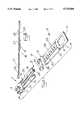
- FIG. 1is a perspective view of an assembled blade according to the present invention.
- FIG. 2is a perspective exploded view of the blade of FIG. 1.
- FIG. 3is a section view of the blade of FIG. 1 taken along line 3-3.
- FIG. 4is a section view of the blade of FIG. 1 taken along line 4-4.
- FIGS. 1-4depict an exemplary oscillating surgical saw blade according to the present invention.
- a hub portion 2comprises an elongated flat plate having top 1 and bottom 3 sides.
- a hub 4is formed at one end. The hub 4 is adapted for engagement with a power tool. In the example shown, the hub 4 includes a plurality of radially oriented holes and slots for engaging pins on the power tool.
- An engagement end 6is formed at the other end opposite the hub 4.
- a blade portion 8comprises an elongated flat plate having top 9 and bottom 11 sides. Teeth 10 are formed at a cutting end. The teeth 10 are adapted for cutting bone or other materials.
- An engagement end 12is formed at the other end opposite the teeth 10. The engagement ends 6 and 12 fit together to form a saw blade having both a hub 4 and teeth 10.
- the engagement ends 6 and 12carry a releasable fastener to hold them in engagement to form a saw blade of a particular length.
- the lockis released, the engagement ends 6 and 12 are moved relative to one another, and the lock reengaged.
- An optional locking sleeve 14can be slid to enclose the engagement ends 6 and 12 to more securely hold them in engagement.
- the releasable fastenerincludes a tongue and groove arrangement that is secured with a button in a hole.
- the engagement end 6 of the hub portion 2includes two cantilevered side arms 16 and a cantilevered central arm 18.
- the arms 16 and 18are formed by milling them from the flat plate of the hub portion 2.
- the arms 16 and 18are attached to the hub portion 2 near the hub 4 and project away from the hub 4.
- the top of the central arm 18is milled below the top side 1 of the hub portion to form a relieved top surface 20.
- the bottoms of the side arms 16are milled above the bottom side 2 of the hub portion 2 to form relieved lower surfaces 22.
- the end of the central arm 18 away from the hub 4carries a button 24.
- the central arm 18is bent so that it is biased upwardly between the side arms 16.
- the engagement end of the blade portionincludes a central web 26 extending between the end containing the teeth 10 and the engagement end 12.
- a series of through holes 28is formed in the central web 26 along its length.
- a groove 29is formed in the bottom of the central web 26 by milling above the bottom side 11 along the length of the central web 26.
- Adjacent to each side of the central web 26, running along the length of the central web 26,are two relieved lateral surfaces 30 formed by milling below the top side 9 of the blade portion 8.
- the blade portion locking sleeve relief 32provides a recess for the locking sleeve 14 so that it does not project below the bottom side 11.
- materialis preferably removed from the tops of the side arms 16 to provide a hub portion locking sleeve relief 34.
- the optional locking sleeve 14comprises a channel sized to slip onto the blade portion 8.
- the locking sleeve 14is a C-shaped channel made from thin metal sheet stock having an open side 36 and a closed side 38. The open side 36 of the locking sleeve 14 is adapted to straddle the central web 26.
- the central arm 18is flexed downwardly so that it is parallel to the side arms 16.
- the engagement ends 6 and 12are brought together so that the side arms 16 slide along the lateral surfaces 30 and the central arm 18 slides in the groove 29.
- the bias of the central arm 18causes it to press into the groove 29.
- the button 24aligns with a hole 28 it will snap into the hole 28 and prevent the hub portion 2 and blade portion 8 from moving relative to one another.
- the bladefits together with an overall thickness no greater than the thickness of the hub 4, since the lateral surfaces 30 and groove 29 are relieved on sides opposite to the sides that the side arms 16 and central arms 18 are relieved on.
- the central arm 18is flexed downwardly away from the groove 29 in order to remove the button 24 from the hole 28.
- the central arm 18can be flexed by pressing; directly on the central arm 18 or by flexing the teeth 10 and hub 4 upwardly causing the blade to bow and the free end of the central web 26 to press against the central arm 18 and flex it back.
- the hub and blade portions 2 and 8are repositioned relative to one another to the desired overall blade length and the central arm 18 is released so that the button 24 can secure the portions.
- the optional locking sleeve 14To use the optional locking sleeve 14, it is slipped onto the blade portion 8 prior to combining the two engagement ends 6 and 12. The engagement ends 6 and 12 are then assembled as described above. To lock the engagement ends 6 and 12 and prevent the button 24 from disengaging from the hole 28, the locking sleeve is slid to enclose the overlapping portions of the engagement ends 6 and 12. The closed side 38 of the locking sleeve 14 lies in the blade portion locking sleeve relief 32 and the open side 36 ends of the locking sleeve 14 lie in the hub side locking sleeve relief 34 so that the locking sleeve 14 does not project beyond the top or bottom sides 1 and 2.
Landscapes
- Health & Medical Sciences (AREA)
- Engineering & Computer Science (AREA)
- Life Sciences & Earth Sciences (AREA)
- Mechanical Engineering (AREA)
- Surgery (AREA)
- Heart & Thoracic Surgery (AREA)
- Nuclear Medicine, Radiotherapy & Molecular Imaging (AREA)
- Biomedical Technology (AREA)
- Oral & Maxillofacial Surgery (AREA)
- Medical Informatics (AREA)
- Molecular Biology (AREA)
- Animal Behavior & Ethology (AREA)
- General Health & Medical Sciences (AREA)
- Public Health (AREA)
- Veterinary Medicine (AREA)
- Dentistry (AREA)
- Surgical Instruments (AREA)
Abstract
Description
The present invention relates to saw blades and more particularly to saw blades for orthopaedic surgery.
There are many instances when it is desirable to change the length of a saw blade. An example is a surgical operation to replace a diseased knee joint. In such an operation a saw blade, often an oscillating blade, is inserted through a plurality of slots in a cutting block to cut the end of the femur to a desired shape. It is preferred that the blade extend only slightly farther than is required to make the desired cut so that adjacent tissues are not unneccessarily cut. Since the different cutting slots often have different dimensions, it is necessary to use a different length of saw blade with each slot. Some surgeons place a piece of adhesive tape on the saw blade to indicate the amount of blade to use for a particular cut. The surgeon then must restrain the saw blade manually to prevent it from engaging the slot deeper than the depth indicated by the tape. U.S. Pat. No. 4,461,296 issued to Hodge teaches a surgical saw blade having a guard fixed a predetermined distance from the cutting edge to control the depth of cut. Similarly, U.S. Pat. No. 4,637,391 issued to Schlein teaches a surgical saw blade having a depth guard releasably secured to the blade. The position of the stop is adjustable in order to adjust the depth of the cut. U.S. Pat. No. 5,382,249 issued to Fletcher teaches another way to control the amount of saw blade used. Fletcher teaches several spaced-apart pairs of notches disposed in the blade edges. Each pair of notches is adapted to engage a pair of pins in the power tool. The mount of blade extending beyond the tool is adjustable by changing the position of the blade within the tool.
The present invention provides a surgical saw blade having two portions that are adjustable relative to one another in order to vary the overall length of the saw blade. A hub portion includes a hub adapted to engage a saw. Opposite the hub is an engagement end. A blade portion carries cutting teeth. Opposite the teeth is an engagement end. The engagement end of the blade portion engages the engagement end of the hub portion. The engagement ends carry a releasable lock to hold them in engagement to form a saw blade of a particular length. To change the saw blade length, the lock is released, the engagement ends moved relative to one another, and the lock reengaged. A locking sleeve can be slid to enclose the engagement portions to more securely hold them in engagement. In addition to allowing the blade length to be adjusted, the present invention allows the cutting portion to be changed while leaving the hub portion attached to the saw. This is useful when it is desired to change a dulled cutting portion or to change to a different size or style cutting portion. Economy can be realized in manufacturing and inventory if the hub portion is reusable and only the blade portion is disposable. One standard blade portion cart be made and put into inventory that can be used with the hub portion to provide many different overall blade lengths.
FIG. 1 is a perspective view of an assembled blade according to the present invention.
FIG. 2 is a perspective exploded view of the blade of FIG. 1.
FIG. 3 is a section view of the blade of FIG. 1 taken along line 3-3.
FIG. 4 is a section view of the blade of FIG. 1 taken along line 4-4.
FIGS. 1-4 depict an exemplary oscillating surgical saw blade according to the present invention. Ahub portion 2 comprises an elongated flat plate having top 1 andbottom 3 sides. A hub 4 is formed at one end. The hub 4 is adapted for engagement with a power tool. In the example shown, the hub 4 includes a plurality of radially oriented holes and slots for engaging pins on the power tool. Anengagement end 6 is formed at the other end opposite the hub 4. A blade portion 8 comprises an elongated flat plate having top 9 and bottom 11 sides.Teeth 10 are formed at a cutting end. Theteeth 10 are adapted for cutting bone or other materials. Anengagement end 12 is formed at the other end opposite theteeth 10. The engagement ends 6 and 12 fit together to form a saw blade having both a hub 4 andteeth 10. The engagement ends 6 and 12 carry a releasable fastener to hold them in engagement to form a saw blade of a particular length. To change the saw blade length, the lock is released, the engagement ends 6 and 12 are moved relative to one another, and the lock reengaged. Anoptional locking sleeve 14 can be slid to enclose theengagement ends
In the embodiment shown, the releasable fastener includes a tongue and groove arrangement that is secured with a button in a hole. Theengagement end 6 of thehub portion 2 includes two cantileveredside arms 16 and a cantileveredcentral arm 18. Preferably thearms hub portion 2. Thearms hub portion 2 near the hub 4 and project away from the hub 4. The top of thecentral arm 18 is milled below the top side 1 of the hub portion to form a relievedtop surface 20. The bottoms of theside arms 16 are milled above thebottom side 2 of thehub portion 2 to form relievedlower surfaces 22. The end of thecentral arm 18 away from the hub 4 carries abutton 24. Thecentral arm 18 is bent so that it is biased upwardly between theside arms 16.
The engagement end of the blade portion includes acentral web 26 extending between the end containing theteeth 10 and theengagement end 12. A series of throughholes 28 is formed in thecentral web 26 along its length. Agroove 29 is formed in the bottom of thecentral web 26 by milling above the bottom side 11 along the length of thecentral web 26. Adjacent to each side of thecentral web 26, running along the length of thecentral web 26, are two relievedlateral surfaces 30 formed by milling below the top side 9 of the blade portion 8.
Preferably material is removed across the bottom side 11 of the blade portion 8, opposite the lateral surfaces 30, to provide a blade portion lockingsleeve relief 32. The blade portion lockingsleeve relief 32 provides a recess for the lockingsleeve 14 so that it does not project below the bottom side 11. Similarly, material is preferably removed from the tops of theside arms 16 to provide a hub portion lockingsleeve relief 34. Theoptional locking sleeve 14 comprises a channel sized to slip onto the blade portion 8. Preferably the lockingsleeve 14 is a C-shaped channel made from thin metal sheet stock having anopen side 36 and aclosed side 38. Theopen side 36 of the lockingsleeve 14 is adapted to straddle thecentral web 26.
To assemble the saw blade, thecentral arm 18 is flexed downwardly so that it is parallel to theside arms 16. The engagement ends 6 and 12 are brought together so that theside arms 16 slide along the lateral surfaces 30 and thecentral arm 18 slides in thegroove 29. The bias of thecentral arm 18 causes it to press into thegroove 29. When thebutton 24 aligns with ahole 28 it will snap into thehole 28 and prevent thehub portion 2 and blade portion 8 from moving relative to one another. The blade fits together with an overall thickness no greater than the thickness of the hub 4, since the lateral surfaces 30 andgroove 29 are relieved on sides opposite to the sides that theside arms 16 andcentral arms 18 are relieved on. To adjust the blade's length, thecentral arm 18 is flexed downwardly away from thegroove 29 in order to remove thebutton 24 from thehole 28. Thecentral arm 18 can be flexed by pressing; directly on thecentral arm 18 or by flexing theteeth 10 and hub 4 upwardly causing the blade to bow and the free end of thecentral web 26 to press against thecentral arm 18 and flex it back. The hub andblade portions 2 and 8 are repositioned relative to one another to the desired overall blade length and thecentral arm 18 is released so that thebutton 24 can secure the portions.
To use theoptional locking sleeve 14, it is slipped onto the blade portion 8 prior to combining the two engagement ends 6 and 12. The engagement ends 6 and 12 are then assembled as described above. To lock the engagement ends 6 and 12 and prevent thebutton 24 from disengaging from thehole 28, the locking sleeve is slid to enclose the overlapping portions of the engagement ends 6 and 12. Theclosed side 38 of the lockingsleeve 14 lies in the blade portion lockingsleeve relief 32 and theopen side 36 ends of the lockingsleeve 14 lie in the hub side lockingsleeve relief 34 so that the lockingsleeve 14 does not project beyond the top orbottom sides 1 and 2.
It will be understood by those skilled in the art that the foregoing has described a preferred embodiment of the present invention and that variations in design and construction may be made to the preferred embodiment without departing from the spirit and scope of the invention defined by the appended claims.
Claims (4)
1. A saw blade having a longitudinal axis, the saw blade comprising; a hub portion, a blade portion engaging the hub portion, the blade portion including a cutting end, and a locking mechanism carried by the hub and blade portions, the locking mechanism releasably preventing relative motion between the hub and blade portions, the hub and blade portions being configured to be assembled and locked in a first position in which the hub and cutting end are spaced a first distance along the longitudinal axis, and the hub and blade portions being configured to be assembled in a second position in which the hub and cutting end are spaced a second distance along the longitudinal axis, wherein the hub portion includes a hub end and an engagement end and the blade portion includes a cutting end and an engagement end, the engagement ends of the hub and blade portions being slidingly engageable to guide the hub and blade portions in relative sliding motion along the longitudinal axis, the locking mechanism being operable between a first position in which it prevents relative motion between the hub and blade portions along the longitudinal axis and a second position in which it allows relative motion between the hub and blade portions along the longitudinal axis, further wherein the engagement ends of the hub and blade portions are engageable in a tongue-and-groove fashion, the hub portion having a pair of side arms extending from the hub parallel to the longitudinal axis and a central arm extending from the hub parallel to the longitudinal axis between the side arms, the blade portion having a pair of lateral surfaces extending from the cutting end parallel to the longitudinal axis, the lateral surfaces being joined along their length by a central web, the hub and blade portions engaging one another with the side arms lying on top of the lateral surfaces and the central arm lying below the central web.
2. The saw blade of claim 1 wherein the central web includes a plurality of holes spaced along its length and the central arm carries a button, the central arm being biased toward the central web, the button being adapted to fit within each of the holes.
3. The saw blade of claim 2 further comprising a locking sleeve, the locking sleeve slightingly engaging the blade, the locking sleeve being movable from a first position in which it prevents the central arm from moving away from the central web to a second position in which it does not prevent the central arm from moving away from the central web.
4. A saw blade having a longitudinal axis, a first end, a second end, and a length as measured from the first end to the second end, the saw blade comprising two separate portions joined together and releasably locked by a locking mechanism to prevent relative motion along the longitudinal axis of the first end relative to the second end, the locking mechanism being operable to allow relative motion between the hub and blade portions along the longitudinal axis so that the length of the saw blade may be adjusted.
Priority Applications (1)
| Application Number | Priority Date | Filing Date | Title |
|---|---|---|---|
| US08/715,945US5735866A (en) | 1996-09-19 | 1996-09-19 | Adjustable length saw blade |
Applications Claiming Priority (1)
| Application Number | Priority Date | Filing Date | Title |
|---|---|---|---|
| US08/715,945US5735866A (en) | 1996-09-19 | 1996-09-19 | Adjustable length saw blade |
Related Child Applications (1)
| Application Number | Title | Priority Date | Filing Date |
|---|---|---|---|
| US09/097,374ContinuationUS6016821A (en) | 1981-02-10 | 1998-06-15 | Systems and methods for ultrasonically processing delicate parts |
Publications (1)
| Publication Number | Publication Date |
|---|---|
| US5735866Atrue US5735866A (en) | 1998-04-07 |
Family
ID=24876104
Family Applications (1)
| Application Number | Title | Priority Date | Filing Date |
|---|---|---|---|
| US08/715,945Expired - LifetimeUS5735866A (en) | 1996-09-19 | 1996-09-19 | Adjustable length saw blade |
Country Status (1)
| Country | Link |
|---|---|
| US (1) | US5735866A (en) |
Cited By (64)
| Publication number | Priority date | Publication date | Assignee | Title |
|---|---|---|---|---|
| US6105260A (en)* | 1998-01-23 | 2000-08-22 | Alterra Holdings Corporation | Universal saw adapter |
| USD455490S1 (en) | 1998-11-06 | 2002-04-09 | Microaire Surgical Instruments, Inc. | Surgical saw blade hub |
| USD459805S1 (en) | 1998-11-06 | 2002-07-02 | Microaire Surgical Instruments, Inc. | Surgical saw blade hub with tangs |
| US20020133185A1 (en)* | 2001-03-14 | 2002-09-19 | Karl-Heinz Danger | Surgical saw blade comprising recesses in the working area |
| US20030176867A1 (en)* | 2002-03-12 | 2003-09-18 | Long Jack F. | Blade for resection of bone for prosthesis implantation, blade stop and method |
| US20030176225A1 (en)* | 2001-12-19 | 2003-09-18 | Hansjoerg Besch | Balanced oscillating tool |
| USD489823S1 (en) | 2003-01-14 | 2004-05-11 | Synvasive Technology, Inc. | Surgical saw blade hub |
| US20040204731A1 (en)* | 2002-11-12 | 2004-10-14 | Stryker Instruments | Surgical saw blade coupler |
| WO2004105623A1 (en) | 2003-05-28 | 2004-12-09 | Aesculap Ag & Co. Kg | Surgical saw-blade |
| DE10325392A1 (en)* | 2003-05-28 | 2004-12-23 | Aesculap Ag & Co. Kg | Surgical saw blade for oscillation saw used for sawing bones during e.g. orthopedic operations, has frame and row of teeth which comprise separate portions |
| US20050245935A1 (en)* | 2004-04-29 | 2005-11-03 | Casey Conor P | Surgical saw blade |
| US20060009796A1 (en)* | 2004-07-09 | 2006-01-12 | Steven Carusillo | Surgical sagittal saw and method of using same |
| US20060217729A1 (en)* | 2005-03-09 | 2006-09-28 | Brasseler Usa Medical Llc | Surgical apparatus and tools for same |
| US20070083209A1 (en)* | 2005-09-23 | 2007-04-12 | Synvasive Technology | Transverse acting surgical saw blade |
| US20070123893A1 (en)* | 2005-10-15 | 2007-05-31 | O' Donoghue Denis A | Surgical sagittal saw blade with angled teeth and chip catchment and reciprocating saw blade with broached teeth |
| US20080243125A1 (en)* | 2007-03-26 | 2008-10-02 | Guzman Jose F | System, apparatus, and method for cutting bone during an orthopaedic surgical procedure |
| US20090182338A1 (en)* | 2006-08-21 | 2009-07-16 | Stryker Ireland Ltd. | Method for manufacturing a surgical saw blade with a blade head and raised boss around which the blade head pivots |
| US20090312761A1 (en)* | 2008-06-11 | 2009-12-17 | Medtronic Ps Medical, Inc. | Surgical Cutting Instrument with Dual Surface Interlocking Coupling Arrangement |
| US20090312762A1 (en)* | 2008-06-11 | 2009-12-17 | Medtronic Ps Medical, Inc. | Micro-Saw Blade for Bone-Cutting Surgical Saws |
| US20100064525A1 (en)* | 2005-09-10 | 2010-03-18 | Walen James G | Surgical sagittal saw blade with a static bar and a pivoting blade head, the bar shaped to facilitate holdign the blade to a complementary saw |
| DE102008063239A1 (en)* | 2008-12-16 | 2010-06-17 | Aesculap Ag | Surgical saw blade protection device for knee endoprosthetic application, has insertion opening for opening lateral side and/or distal-side of retaining area for insertion of toothless saw blade section of saw blade |
| US20100292701A1 (en)* | 2009-05-12 | 2010-11-18 | Synvasive Technology, Inc. | Surgical saw blade device and system |
| US20110092975A1 (en)* | 2009-10-21 | 2011-04-21 | Fisher Michael G | Surgical saw device and method of manufacture |
| US20110106092A1 (en)* | 2009-11-02 | 2011-05-05 | Synvasive, Inc. | Bone positioning device and method |
| US20110167643A1 (en)* | 2010-01-12 | 2011-07-14 | Chien-Rung Chen | Versatile survival knife |
| USD654167S1 (en)* | 2009-07-21 | 2012-02-14 | Sevika Holding AG | Surgical saw device |
| US20120289963A1 (en)* | 2010-01-11 | 2012-11-15 | Legrand Bernard P | Surgical blade assembly |
| US20130160631A1 (en)* | 2011-12-27 | 2013-06-27 | Robert Bosch Gmbh | Jab Saw Accessory Tool for an Oscillating Tool |
| WO2013091966A1 (en)* | 2011-12-20 | 2013-06-27 | Robert Bosch Gmbh | Rotary oscillation cutting tool for a machine tool |
| US20130269963A1 (en)* | 2010-08-26 | 2013-10-17 | Robert Bosch Gmbh | System Having at least Two Oscillation Insert Tools |
| US20140035242A1 (en)* | 2010-04-29 | 2014-02-06 | Thomas R. Kaye, Jr. | Universal Accessory for Oscillating Power Tool |
| US20140163558A1 (en)* | 2011-07-27 | 2014-06-12 | Stryker Corporation | Surgical sagittal saw and blade cartridge, the blade cartridge having reinforcing ribs integral with the blade bar |
| US8852221B2 (en) | 2008-06-11 | 2014-10-07 | Medtronic Ps Medical, Inc. | Surgical cutting instrument with near-perimeter interlocking coupling arrangement |
| US8858559B2 (en) | 2012-02-06 | 2014-10-14 | Medtronic Ps Medical, Inc. | Saw blade stability and collet system mechanism |
| USD716944S1 (en) | 2011-08-03 | 2014-11-04 | Synvasive Technology, Inc. | Surgical saw blade hub |
| US8936597B2 (en) | 2012-02-06 | 2015-01-20 | Medtronic Ps Medical, Inc. | Deflectable finger connection feature on surgical saw blade |
| US9095352B2 (en) | 2009-11-02 | 2015-08-04 | Synvasive Technology, Inc. | Bone positioning device and method |
| US20150266102A1 (en)* | 2014-03-21 | 2015-09-24 | Burton Kozak | Tool accessory having a partially removable attachment portion |
| US9149923B2 (en) | 2010-11-09 | 2015-10-06 | Black & Decker Inc. | Oscillating tools and accessories |
| CN105328649A (en)* | 2014-07-01 | 2016-02-17 | 苏州宝时得电动工具有限公司 | Working accessory and power tool |
| US20170129125A1 (en)* | 2015-11-09 | 2017-05-11 | Robert Bosch Tool Corporation | Blade and Blade Attachment System for an Oscillating Tool |
| US20170129126A1 (en)* | 2015-11-09 | 2017-05-11 | Robert Bosch Tool Corporation | Blade and Blade Attachment System for an Oscillating Tool |
| US20170182570A1 (en)* | 2015-12-29 | 2017-06-29 | Robert Bosch Tool Corporation | Saw blade for oscillating tool or handheld tool |
| WO2017214737A1 (en)* | 2016-06-13 | 2017-12-21 | Synthes Gmbh | Saw gear set |
| USD814900S1 (en) | 2017-01-16 | 2018-04-10 | Black & Decker Inc. | Blade for oscillating power tools |
| USD832666S1 (en) | 2012-07-16 | 2018-11-06 | Black & Decker Inc. | Oscillating saw blade |
| CN108883483A (en)* | 2016-04-08 | 2018-11-23 | 罗伯特·博世有限公司 | The blade for swing tool with double installation configurations |
| US10207385B2 (en) | 2010-04-29 | 2019-02-19 | Black & Decker Inc. | Accessories for oscillating power tools |
| US10265778B2 (en) | 2017-01-16 | 2019-04-23 | Black & Decker Inc. | Accessories for oscillating power tools |
| US20190321900A1 (en)* | 2018-04-24 | 2019-10-24 | Robert Bosch Tool Corporation | Blade Accessory with Guide |
| CN110919106A (en)* | 2020-02-12 | 2020-03-27 | 北京罗森博特科技有限公司 | Cutting device for tail end of manipulator and manipulator |
| US10687824B2 (en)* | 2017-07-21 | 2020-06-23 | Stryker European Holdings I, Llc | Surgical saw and saw blade for use therewith |
| EP3746274A1 (en)* | 2018-02-02 | 2020-12-09 | Imperial Blades | Oscillating tool drywall blade |
| EP3769701A3 (en)* | 2019-07-26 | 2021-03-10 | Aesculap AG | Composite saw blade for a medical bone saw |
| US10953563B2 (en) | 2010-03-22 | 2021-03-23 | Universal Arbor LLC | Accessory for oscillating power tool |
| US10966730B2 (en)* | 2019-05-27 | 2021-04-06 | Miyatani Co., Ltd. | Bone resection apparatus |
| USD931069S1 (en)* | 2019-05-03 | 2021-09-21 | Tti (Macao Commercial Offshore) Limited | Blade |
| US11160561B2 (en) | 2015-05-12 | 2021-11-02 | Stryker European Holdings I, Llc | Surgical sagittal blade cartridge with a guide bar |
| US11357644B2 (en) | 2011-10-24 | 2022-06-14 | Synvasive Technology, Inc. | Knee balancing devices, systems and methods |
| US11738398B2 (en) | 2020-11-18 | 2023-08-29 | Milwaukee Electric Tool Corporation | Accessory for an oscillating power tool |
| US11812973B2 (en) | 2018-03-06 | 2023-11-14 | Conmed Corporation | Sheathed surgical saw blade with bearings |
| US20240165722A1 (en)* | 2020-02-25 | 2024-05-23 | Black & Decker Inc. | Accessories for oscillating power tools |
| USD1084334S1 (en) | 2022-06-22 | 2025-07-15 | Stryker European Operations Limited | Surgical blade cartridge |
| USD1084335S1 (en) | 2022-06-22 | 2025-07-15 | Stryker European Operations Limited | Surgical blade cartridge |
Citations (7)
| Publication number | Priority date | Publication date | Assignee | Title |
|---|---|---|---|---|
| US4386609A (en)* | 1979-12-17 | 1983-06-07 | Minnesota Mining And Manufacturing Company | Attaching assembly for an osteotomy saw blade |
| US4461296A (en)* | 1979-04-16 | 1984-07-24 | Joseph Hodge | Surgical saw blade |
| US4617930A (en)* | 1984-05-16 | 1986-10-21 | Queen's University At Kingston | Blade stiffener |
| US4637391A (en)* | 1986-04-03 | 1987-01-20 | Schlein Allen P | Surgical saw blade |
| US5178626A (en)* | 1989-01-13 | 1993-01-12 | Pappas Michael J | Stepped surgical saw blade |
| US5382249A (en)* | 1991-05-30 | 1995-01-17 | Synvasive Technology, Inc. | Adjustable surgical blade |
| US5439472A (en)* | 1991-01-11 | 1995-08-08 | Stryker Corporation | Surgical handpiece chuck and blade |
- 1996
- 1996-09-19USUS08/715,945patent/US5735866A/ennot_activeExpired - Lifetime
Patent Citations (7)
| Publication number | Priority date | Publication date | Assignee | Title |
|---|---|---|---|---|
| US4461296A (en)* | 1979-04-16 | 1984-07-24 | Joseph Hodge | Surgical saw blade |
| US4386609A (en)* | 1979-12-17 | 1983-06-07 | Minnesota Mining And Manufacturing Company | Attaching assembly for an osteotomy saw blade |
| US4617930A (en)* | 1984-05-16 | 1986-10-21 | Queen's University At Kingston | Blade stiffener |
| US4637391A (en)* | 1986-04-03 | 1987-01-20 | Schlein Allen P | Surgical saw blade |
| US5178626A (en)* | 1989-01-13 | 1993-01-12 | Pappas Michael J | Stepped surgical saw blade |
| US5439472A (en)* | 1991-01-11 | 1995-08-08 | Stryker Corporation | Surgical handpiece chuck and blade |
| US5382249A (en)* | 1991-05-30 | 1995-01-17 | Synvasive Technology, Inc. | Adjustable surgical blade |
Non-Patent Citations (2)
| Title |
|---|
| Hall Oscillating Saw Blades, pp. 2, 3 The Hall Blade and Bur Book Literature No. 97 3000 320, Rev. A, c1991.* |
| Hall Oscillating Saw Blades, pp. 2, 3 -The Hall® Blade and Bur Book -Literature No. 97-3000-320, Rev. A, c1991. |
Cited By (152)
| Publication number | Priority date | Publication date | Assignee | Title |
|---|---|---|---|---|
| US6508003B1 (en) | 1998-01-23 | 2003-01-21 | Alterra Holdings Corporation | Universal saw adapter |
| US6105260A (en)* | 1998-01-23 | 2000-08-22 | Alterra Holdings Corporation | Universal saw adapter |
| USD455490S1 (en) | 1998-11-06 | 2002-04-09 | Microaire Surgical Instruments, Inc. | Surgical saw blade hub |
| USD459805S1 (en) | 1998-11-06 | 2002-07-02 | Microaire Surgical Instruments, Inc. | Surgical saw blade hub with tangs |
| US6896679B2 (en)* | 2001-03-14 | 2005-05-24 | Gebr, Brassler Gmbh & Co. Kg | Surgical saw blade comprising recesses in the working area |
| US20020133185A1 (en)* | 2001-03-14 | 2002-09-19 | Karl-Heinz Danger | Surgical saw blade comprising recesses in the working area |
| US20030176225A1 (en)* | 2001-12-19 | 2003-09-18 | Hansjoerg Besch | Balanced oscillating tool |
| US6875222B2 (en)* | 2002-03-12 | 2005-04-05 | Depuy Products, Inc. | Blade for resection of bone for prosthesis implantation, blade stop and method |
| US20030176867A1 (en)* | 2002-03-12 | 2003-09-18 | Long Jack F. | Blade for resection of bone for prosthesis implantation, blade stop and method |
| US20040204731A1 (en)* | 2002-11-12 | 2004-10-14 | Stryker Instruments | Surgical saw blade coupler |
| US7833241B2 (en) | 2002-11-12 | 2010-11-16 | Stryker Corporation | Surgical saw blade coupler |
| USD489823S1 (en) | 2003-01-14 | 2004-05-11 | Synvasive Technology, Inc. | Surgical saw blade hub |
| WO2004105623A1 (en) | 2003-05-28 | 2004-12-09 | Aesculap Ag & Co. Kg | Surgical saw-blade |
| DE10325392A1 (en)* | 2003-05-28 | 2004-12-23 | Aesculap Ag & Co. Kg | Surgical saw blade for oscillation saw used for sawing bones during e.g. orthopedic operations, has frame and row of teeth which comprise separate portions |
| EP1880682A2 (en) | 2003-05-28 | 2008-01-23 | AESCULAP AG & Co. KG | Surgical saw blade |
| DE10325392B4 (en)* | 2003-05-28 | 2009-02-05 | Aesculap Ag | Surgical saw blade, in particular for an oscillating saw |
| EP1880682A3 (en)* | 2003-05-28 | 2008-02-20 | AESCULAP AG & Co. KG | Surgical saw blade |
| US20050245935A1 (en)* | 2004-04-29 | 2005-11-03 | Casey Conor P | Surgical saw blade |
| US9848887B2 (en) | 2004-07-09 | 2017-12-26 | Stryker Corporation | Integrated cutting guide and surgical saw blade assembly, the cutting guide including a moveable head that constrains the movement of the blade assembly |
| US11877755B2 (en) | 2004-07-09 | 2024-01-23 | Stryker Corporation | Surgical saw assembly including a surgical saw blade assembly having an oscillating blade |
| US10932794B2 (en) | 2004-07-09 | 2021-03-02 | Stryker Corporation | Surgical blade assembly including a static guide bar and an oscillating blade |
| US9554808B2 (en) | 2004-07-09 | 2017-01-31 | Stryker Corporation | Surgical sagittal saw blade assembly that includes a guide bar, a blade that is pivotally mounted to the guide bar, the blade having a head that extends from a side edge of the guide bar and drive rods that pivot the blade |
| US20110208197A1 (en)* | 2004-07-09 | 2011-08-25 | Steven Carusillo | Integrated cutting guide and sagittal saw blade assembly |
| US7497860B2 (en) | 2004-07-09 | 2009-03-03 | Stryker Corporation | Surgical sagittal saw including a handpiece and a removable blade assembly, the blade assembly including a guide bar, a blade head capable of oscillatory movement and a drive rod for actuating the blade head |
| US20090138017A1 (en)* | 2004-07-09 | 2009-05-28 | Steven Carusillo | Surgical sagittal saw blade including a guide bar, a blade head and drive rods for pivoting the blade head |
| US11083468B2 (en) | 2004-07-09 | 2021-08-10 | Stryker Corporation | Surgical blade assembly including a guide bar and a blade |
| US20060009796A1 (en)* | 2004-07-09 | 2006-01-12 | Steven Carusillo | Surgical sagittal saw and method of using same |
| US9072526B2 (en) | 2004-07-09 | 2015-07-07 | Stryker Corporation | Surgical sagittal saw blade assembly that includes a guide bar including bottom, inner and outer bars and a blade head that pivots around the inner bar |
| US10251651B2 (en) | 2004-07-09 | 2019-04-09 | Stryker Corporation | Surgical reciprocating blade assembly including a static guide bar, teeth that project from a side of the guide bar and a drive rod that reciprocates the teeth |
| US8702710B2 (en) | 2004-07-09 | 2014-04-22 | Stryker Corporation | Surgical sagittal saw capable of actuating a blade assembly that includes a static bar and a drive rod |
| US8403932B2 (en) | 2004-07-09 | 2013-03-26 | Stryker Corporation | Integrated cutting guide and sagittal saw blade assembly |
| US8043292B2 (en) | 2004-07-09 | 2011-10-25 | Stryker Corporation | Surgical sagittal saw blade including a guide bar, a blade head and drive rods for pivoting the blade head |
| US20060217729A1 (en)* | 2005-03-09 | 2006-09-28 | Brasseler Usa Medical Llc | Surgical apparatus and tools for same |
| US8348951B2 (en)* | 2005-09-10 | 2013-01-08 | Stryker Corporation | Sagittal saw blade with a static bar and a moving drive rod and blade crown, the bar having secondary openings |
| US9060783B2 (en) | 2005-09-10 | 2015-06-23 | Stryker Corporation | Surgical sagittal saw for actuating a saw blade with an oscillating head, the saw having a coupling assembly for releaseably holding the saw blade |
| US20100064525A1 (en)* | 2005-09-10 | 2010-03-18 | Walen James G | Surgical sagittal saw blade with a static bar and a pivoting blade head, the bar shaped to facilitate holdign the blade to a complementary saw |
| JP2011067645A (en)* | 2005-09-10 | 2011-04-07 | Stryker Corp | Surgical saw blade with blade bar, pivoting blade head, and driving rod having finger pivotally connecting the blade head |
| US9820753B2 (en) | 2005-09-10 | 2017-11-21 | Stryker Corporation | Surgical sagittal saw blade with a static bar, a pivoting blade head, drive rods that pivot the blade head and fingers that connect the drive rods to the blade head, the fingers being seated in the static bar |
| US12029436B2 (en)* | 2005-09-10 | 2024-07-09 | Stryker European Operations Holdings Llc | Surgical saw for actuating a saw blade with an oscillating head, the saw having a coupling assembly for releasably holding the saw blade |
| US10278710B2 (en) | 2005-09-10 | 2019-05-07 | Stryker Corporation | Surgical sagittal saw blade with a static bar, a pivoting blade head, drive rods that pivot the blade head and a support member |
| US20100228256A1 (en)* | 2005-09-10 | 2010-09-09 | Stryker Corporation | Sagittal saw blade with a static bar and a moving drive rod and blade crown, the bar having secondary openings |
| US8444647B2 (en)* | 2005-09-10 | 2013-05-21 | Stryker Corporation | Surgical sagittal saw blade with a static bar and a pivoting blade head, the bar shaped to facilitate holding the blade to a complementary saw |
| US9445822B2 (en) | 2005-09-10 | 2016-09-20 | Stryker Corporation | Method of assembling the oscillating assembly of a surgical sagittal saw |
| US20220047274A1 (en)* | 2005-09-10 | 2022-02-17 | Stryker Corporation | Surgical Saw for Actuating a Saw Blade with an Oscillating Head, the Saw Having a Coupling Assembly for Releasably Holding the Saw Blade |
| US11179163B2 (en) | 2005-09-10 | 2021-11-23 | Stryker Corporation | Navigated surgical saw assembly and method of navigating the surgical saw assembly |
| US11090061B2 (en)* | 2005-09-10 | 2021-08-17 | Stryker Corporation | Surgical saw blade |
| US8696673B2 (en) | 2005-09-10 | 2014-04-15 | Stryker Corporation | Surgical sagittal saw blade with a biasing assembly that urges the blade assembly used with the saw away from the saw head |
| US20070083209A1 (en)* | 2005-09-23 | 2007-04-12 | Synvasive Technology | Transverse acting surgical saw blade |
| US7691106B2 (en)* | 2005-09-23 | 2010-04-06 | Synvasive Technology, Inc. | Transverse acting surgical saw blade |
| US8216262B2 (en) | 2005-10-15 | 2012-07-10 | Stryker Ireland, Ltd | Surgical sagittal saw blade with spaced apart tines from which the blade teeth emerge and recessed webs that extend between the tines |
| US20100262148A1 (en)* | 2005-10-15 | 2010-10-14 | Stryker Ireland Ltd. | Surgical sagittal saw blade with spaced apart tines from which the blade teeth emerge and recessed webs that extend between the tines |
| US7744616B2 (en)* | 2005-10-15 | 2010-06-29 | Stryker Ireland, Ltd. | Surgical sagittal saw blade with angled teeth and chip catchment and reciprocating saw blade with broached teeth |
| US20070123893A1 (en)* | 2005-10-15 | 2007-05-31 | O' Donoghue Denis A | Surgical sagittal saw blade with angled teeth and chip catchment and reciprocating saw blade with broached teeth |
| US20090182338A1 (en)* | 2006-08-21 | 2009-07-16 | Stryker Ireland Ltd. | Method for manufacturing a surgical saw blade with a blade head and raised boss around which the blade head pivots |
| US8323285B2 (en)* | 2006-08-21 | 2012-12-04 | Stryker Ireland, Ltd. | Method for manufacturing a surgical saw blade with a blade head and raised boss around which the blade head pivots |
| US20080243125A1 (en)* | 2007-03-26 | 2008-10-02 | Guzman Jose F | System, apparatus, and method for cutting bone during an orthopaedic surgical procedure |
| US10327784B2 (en) | 2007-03-26 | 2019-06-25 | DePuy Synthes Products, Inc. | Method for cutting bone during an orthopaedic surgical procedure |
| US11219465B2 (en) | 2007-03-26 | 2022-01-11 | DePuy Synthes Products, Inc. | System, apparatus, and method for cutting bone during an orthopaedic surgical procedure |
| US8608745B2 (en) | 2007-03-26 | 2013-12-17 | DePuy Synthes Products, LLC | System, apparatus, and method for cutting bone during an orthopaedic surgical procedure |
| EP1974679A3 (en)* | 2007-03-26 | 2008-11-26 | DePuy Products, Inc. | Apparatus for cutting bone during orthopaedic surgery |
| US11998218B2 (en) | 2007-03-26 | 2024-06-04 | DePuy Synthes Products, Inc. | System, apparatus, and method for cutting bone during an orthopaedic surgical procedure |
| US20170086856A1 (en)* | 2008-06-11 | 2017-03-30 | Medtronic Ps Medical, Inc. | Surgical Cutting Instrument With Near-Perimeter Interlocking Coupling Arrangement |
| US8852221B2 (en) | 2008-06-11 | 2014-10-07 | Medtronic Ps Medical, Inc. | Surgical cutting instrument with near-perimeter interlocking coupling arrangement |
| US8523868B2 (en) | 2008-06-11 | 2013-09-03 | Medtronic Ps Medical, Inc. | Surgical cutting instrument with dual surface interlocking coupling arrangement |
| US20090312761A1 (en)* | 2008-06-11 | 2009-12-17 | Medtronic Ps Medical, Inc. | Surgical Cutting Instrument with Dual Surface Interlocking Coupling Arrangement |
| US8920424B2 (en)* | 2008-06-11 | 2014-12-30 | Medtronic Ps Medical, Inc. | Micro-saw blade for bone-cutting surgical saws |
| US10856885B2 (en)* | 2008-06-11 | 2020-12-08 | Medtronic Ps Medical, Inc. | Surgical cutting instrument with near-perimeter interlocking coupling arrangement |
| US9517074B2 (en) | 2008-06-11 | 2016-12-13 | Medtronic Ps Medical, Inc. | Surgical cutting instrument with near-perimeter interlocking coupling arrangement |
| US20150112347A1 (en)* | 2008-06-11 | 2015-04-23 | Medtronic Ps Medical, Inc. | Micro-Saw Blade For Bone-Cutting Surgical Saws |
| US9414845B2 (en)* | 2008-06-11 | 2016-08-16 | Medtronic Ps Medical, Inc. | Micro-saw blade for bone-cutting surgical saws |
| US10182826B2 (en)* | 2008-06-11 | 2019-01-22 | Medtronic Ps Medical, Inc. | Surgical cutting instrument with near-perimeter interlocking coupling arrangement |
| US9402635B2 (en) | 2008-06-11 | 2016-08-02 | Medtronic Ps Medical, Inc. | Surgical cutting instrument with dual surface interlocking coupling arrangement |
| US20090312762A1 (en)* | 2008-06-11 | 2009-12-17 | Medtronic Ps Medical, Inc. | Micro-Saw Blade for Bone-Cutting Surgical Saws |
| DE102008063239A1 (en)* | 2008-12-16 | 2010-06-17 | Aesculap Ag | Surgical saw blade protection device for knee endoprosthetic application, has insertion opening for opening lateral side and/or distal-side of retaining area for insertion of toothless saw blade section of saw blade |
| US20100292701A1 (en)* | 2009-05-12 | 2010-11-18 | Synvasive Technology, Inc. | Surgical saw blade device and system |
| US8672943B2 (en) | 2009-05-12 | 2014-03-18 | Synvasive Technology, Inc. | Surgical saw blade device and system |
| USD654167S1 (en)* | 2009-07-21 | 2012-02-14 | Sevika Holding AG | Surgical saw device |
| US8636739B2 (en) | 2009-10-21 | 2014-01-28 | Synvasive Technology, Inc. | Surgical saw device and method of manufacture |
| US20110092975A1 (en)* | 2009-10-21 | 2011-04-21 | Fisher Michael G | Surgical saw device and method of manufacture |
| US8206392B2 (en) | 2009-10-21 | 2012-06-26 | Synvasive Technology, Inc. | Surgical saw device and method of manufacture |
| US8828013B2 (en) | 2009-11-02 | 2014-09-09 | Synvasive Technology, Inc. | Bone positioning device and method |
| US9693783B2 (en) | 2009-11-02 | 2017-07-04 | Synvasive Technology, Inc. | Bone positioning device and method |
| US9095352B2 (en) | 2009-11-02 | 2015-08-04 | Synvasive Technology, Inc. | Bone positioning device and method |
| US20110106092A1 (en)* | 2009-11-02 | 2011-05-05 | Synvasive, Inc. | Bone positioning device and method |
| US8966772B2 (en)* | 2010-01-11 | 2015-03-03 | Zimmer Surgical Sa | Surgical blade assembly |
| US20120289963A1 (en)* | 2010-01-11 | 2012-11-15 | Legrand Bernard P | Surgical blade assembly |
| US20110167643A1 (en)* | 2010-01-12 | 2011-07-14 | Chien-Rung Chen | Versatile survival knife |
| US11446840B2 (en) | 2010-03-22 | 2022-09-20 | Universal Arbor LLC | Accessory for oscillating power tool |
| US10953563B2 (en) | 2010-03-22 | 2021-03-23 | Universal Arbor LLC | Accessory for oscillating power tool |
| US11097396B2 (en) | 2010-04-29 | 2021-08-24 | Black & Decker Inc. | Accessories for oscillating power tools |
| US20140035242A1 (en)* | 2010-04-29 | 2014-02-06 | Thomas R. Kaye, Jr. | Universal Accessory for Oscillating Power Tool |
| US9073195B2 (en)* | 2010-04-29 | 2015-07-07 | Black & Decker Inc. | Universal accessory for oscillating power tool |
| US10207385B2 (en) | 2010-04-29 | 2019-02-19 | Black & Decker Inc. | Accessories for oscillating power tools |
| US10040186B2 (en) | 2010-04-29 | 2018-08-07 | Black & Decker Inc. | Universal accessories for oscillating power tools |
| US20130269963A1 (en)* | 2010-08-26 | 2013-10-17 | Robert Bosch Gmbh | System Having at least Two Oscillation Insert Tools |
| US10112294B2 (en)* | 2010-08-26 | 2018-10-30 | Robert Bosch Gmbh | System having at least two oscillation insert tools |
| US9149923B2 (en) | 2010-11-09 | 2015-10-06 | Black & Decker Inc. | Oscillating tools and accessories |
| US9439655B2 (en)* | 2011-07-27 | 2016-09-13 | Stryker Ireland Ltd. | Surgical sagittal saw and blade cartridge, the blade cartridge having reinforcing ribs integral with the blade bar |
| US20140163558A1 (en)* | 2011-07-27 | 2014-06-12 | Stryker Corporation | Surgical sagittal saw and blade cartridge, the blade cartridge having reinforcing ribs integral with the blade bar |
| USD716944S1 (en) | 2011-08-03 | 2014-11-04 | Synvasive Technology, Inc. | Surgical saw blade hub |
| US11357644B2 (en) | 2011-10-24 | 2022-06-14 | Synvasive Technology, Inc. | Knee balancing devices, systems and methods |
| WO2013091966A1 (en)* | 2011-12-20 | 2013-06-27 | Robert Bosch Gmbh | Rotary oscillation cutting tool for a machine tool |
| US20130160631A1 (en)* | 2011-12-27 | 2013-06-27 | Robert Bosch Gmbh | Jab Saw Accessory Tool for an Oscillating Tool |
| US9027452B2 (en)* | 2011-12-27 | 2015-05-12 | Robert Bosch Gmbh | Jab saw accessory tool for an oscillating tool |
| US9566074B2 (en) | 2012-02-06 | 2017-02-14 | Medtronic Ps Medical, Inc. | Saw blade stability and collet system mechanism |
| US9603603B2 (en) | 2012-02-06 | 2017-03-28 | Medtronic Ps Medical, Inc. | Deflectable finger connection feature on surgical saw blade |
| US8858559B2 (en) | 2012-02-06 | 2014-10-14 | Medtronic Ps Medical, Inc. | Saw blade stability and collet system mechanism |
| US8936597B2 (en) | 2012-02-06 | 2015-01-20 | Medtronic Ps Medical, Inc. | Deflectable finger connection feature on surgical saw blade |
| US10245716B2 (en) | 2012-07-16 | 2019-04-02 | Black & Decker Inc. | Universal accessories for oscillating power tools |
| USD832666S1 (en) | 2012-07-16 | 2018-11-06 | Black & Decker Inc. | Oscillating saw blade |
| US11235452B2 (en) | 2012-07-16 | 2022-02-01 | Black & Decker Inc. | Accessories for oscillating power tools |
| USD873099S1 (en) | 2012-07-16 | 2020-01-21 | Black & Decker Inc. | Oscillating saw blade |
| USD884444S1 (en) | 2012-07-16 | 2020-05-19 | Black & Decker Inc. | Oscillating saw blade |
| US10792801B2 (en) | 2012-07-16 | 2020-10-06 | Black & Decker Inc. | Oscillating power tools and accessories |
| USD856766S1 (en) | 2012-07-16 | 2019-08-20 | Black & Decker Inc. | Oscillating saw blade |
| US9815187B2 (en)* | 2014-03-21 | 2017-11-14 | Burton Kozak | Tool accessory having a partially removable attachment portion |
| US20150266102A1 (en)* | 2014-03-21 | 2015-09-24 | Burton Kozak | Tool accessory having a partially removable attachment portion |
| CN105328649B (en)* | 2014-07-01 | 2019-03-29 | 苏州宝时得电动工具有限公司 | Working accessory and power tool |
| CN105328649A (en)* | 2014-07-01 | 2016-02-17 | 苏州宝时得电动工具有限公司 | Working accessory and power tool |
| US11890021B2 (en) | 2015-05-12 | 2024-02-06 | Stryker European Operations Holdings Llc | Surgical sagittal blade cartridge with a reinforced guide bar |
| US11160561B2 (en) | 2015-05-12 | 2021-11-02 | Stryker European Holdings I, Llc | Surgical sagittal blade cartridge with a guide bar |
| US20170129125A1 (en)* | 2015-11-09 | 2017-05-11 | Robert Bosch Tool Corporation | Blade and Blade Attachment System for an Oscillating Tool |
| US10040215B2 (en)* | 2015-11-09 | 2018-08-07 | Robert Bosch Tool Corporation | Blade and blade attachment system for an oscillating tool |
| US10011036B2 (en)* | 2015-11-09 | 2018-07-03 | Robert Bosch Tool Corporation | Blade and blade attachment system for an oscillating tool |
| US20170129126A1 (en)* | 2015-11-09 | 2017-05-11 | Robert Bosch Tool Corporation | Blade and Blade Attachment System for an Oscillating Tool |
| US20170182570A1 (en)* | 2015-12-29 | 2017-06-29 | Robert Bosch Tool Corporation | Saw blade for oscillating tool or handheld tool |
| US10442020B2 (en)* | 2015-12-29 | 2019-10-15 | Robert Bosch Tool Corporation | Saw blade for oscillating tool or handheld tool |
| CN108883483A (en)* | 2016-04-08 | 2018-11-23 | 罗伯特·博世有限公司 | The blade for swing tool with double installation configurations |
| US11844530B2 (en) | 2016-06-13 | 2023-12-19 | Synthes Gmbh | Saw gear set |
| WO2017214737A1 (en)* | 2016-06-13 | 2017-12-21 | Synthes Gmbh | Saw gear set |
| US11202638B2 (en) | 2016-06-13 | 2021-12-21 | Synthes Gmbh | Saw gear set |
| USD924030S1 (en) | 2017-01-16 | 2021-07-06 | Black & Decker Inc. | Blade for oscillating power tools |
| US10702927B2 (en) | 2017-01-16 | 2020-07-07 | Black & Decker Inc. | Accessories for oscillating power tools |
| US10265778B2 (en) | 2017-01-16 | 2019-04-23 | Black & Decker Inc. | Accessories for oscillating power tools |
| USD871185S1 (en) | 2017-01-16 | 2019-12-31 | Black & Decker Inc. | Blade for oscillating power tools |
| US12070803B2 (en) | 2017-01-16 | 2024-08-27 | Black & Decker Inc. | Accessories for oscillating power tools |
| USD814900S1 (en) | 2017-01-16 | 2018-04-10 | Black & Decker Inc. | Blade for oscillating power tools |
| US10687824B2 (en)* | 2017-07-21 | 2020-06-23 | Stryker European Holdings I, Llc | Surgical saw and saw blade for use therewith |
| EP3746274A1 (en)* | 2018-02-02 | 2020-12-09 | Imperial Blades | Oscillating tool drywall blade |
| US12226843B2 (en) | 2018-02-02 | 2025-02-18 | Imperial Blades | Oscillating tool drywall blade |
| US11812973B2 (en) | 2018-03-06 | 2023-11-14 | Conmed Corporation | Sheathed surgical saw blade with bearings |
| US10906108B2 (en)* | 2018-04-24 | 2021-02-02 | Robert Bosch Tool Corporation | Blade accessory with guide |
| US20190321900A1 (en)* | 2018-04-24 | 2019-10-24 | Robert Bosch Tool Corporation | Blade Accessory with Guide |
| USD931069S1 (en)* | 2019-05-03 | 2021-09-21 | Tti (Macao Commercial Offshore) Limited | Blade |
| USD1015098S1 (en) | 2019-05-03 | 2024-02-20 | Techtronic Power Tools Technology Limited | Blade |
| US10966730B2 (en)* | 2019-05-27 | 2021-04-06 | Miyatani Co., Ltd. | Bone resection apparatus |
| EP3769701A3 (en)* | 2019-07-26 | 2021-03-10 | Aesculap AG | Composite saw blade for a medical bone saw |
| CN110919106A (en)* | 2020-02-12 | 2020-03-27 | 北京罗森博特科技有限公司 | Cutting device for tail end of manipulator and manipulator |
| US20240165722A1 (en)* | 2020-02-25 | 2024-05-23 | Black & Decker Inc. | Accessories for oscillating power tools |
| US11738398B2 (en) | 2020-11-18 | 2023-08-29 | Milwaukee Electric Tool Corporation | Accessory for an oscillating power tool |
| USD1084334S1 (en) | 2022-06-22 | 2025-07-15 | Stryker European Operations Limited | Surgical blade cartridge |
| USD1084335S1 (en) | 2022-06-22 | 2025-07-15 | Stryker European Operations Limited | Surgical blade cartridge |
Similar Documents
| Publication | Publication Date | Title |
|---|---|---|
| US5735866A (en) | Adjustable length saw blade | |
| US6263577B1 (en) | Automatic spring retractable utility knife | |
| US5569260A (en) | Distal femoral resector guide | |
| US4452106A (en) | Tool having articulated opposing jaws | |
| US5002555A (en) | Gall-resistant ribbed surgical saw blade | |
| JP3858201B2 (en) | Distal thigh size measuring instrument | |
| US3798688A (en) | Double edge blade scalpel | |
| US5447516A (en) | Double-bladed scalpel | |
| EP1955628B1 (en) | Food Slicer and Grater | |
| US20080097450A1 (en) | Patella clamp | |
| AU2008335246B2 (en) | Dermatome with orientation guides | |
| US5208983A (en) | Retracting cutter | |
| ES2113621T3 (en) | ORTHOPEDIC CUTTING GUIDES WITH RETRAIBLE SLOTS FOR SAW BLADE. | |
| JPS628175B2 (en) | ||
| US5103564A (en) | Sectioned cutting blade | |
| US8043294B2 (en) | Reference mark adjustment mechanism for a femoral caliper and method of using the same | |
| US20230062460A1 (en) | Utility Knife with Tape Hook Recess | |
| EP2574290B1 (en) | Patella resection assembly | |
| US5071427A (en) | Surgical knife assembly including depth guard | |
| US4712546A (en) | Cutting instrument for nasal surgery which cuts parallel to its length | |
| US5430940A (en) | Scissors combined with a cutter knife | |
| USD404633S (en) | Knife blade | |
| US7565746B2 (en) | Hairdressing scissors | |
| JPH01113086A (en) | Cutting blade and its holder | |
| US5951580A (en) | Scalpel having two blades adjustably separable |
Legal Events
| Date | Code | Title | Description |
|---|---|---|---|
| AS | Assignment | Owner name:BRISTOL-MYERS SQUIBB COMPANY, NEW YORK Free format text:ASSIGNMENT OF ASSIGNORS INTEREST;ASSIGNORS:ADAMS, KENNETH M.;NENU, SORIN;REEL/FRAME:008707/0508 Effective date:19960917 | |
| AS | Assignment | Owner name:LINVATEC CORPORATION, FLORIDA Free format text:ASSIGNMENT OF ASSIGNORS INTEREST;ASSIGNOR:BRISTOL-MYERS SQUIBB COMPANY;REEL/FRAME:008753/0215 Effective date:19971003 | |
| STCF | Information on status: patent grant | Free format text:PATENTED CASE | |
| FPAY | Fee payment | Year of fee payment:4 | |
| AS | Assignment | Owner name:JPMORGAN CHASE BANK, AS ADMINISTRATIVE AGENT, TEXA Free format text:SECURITY INTEREST;ASSIGNOR:LINVATEC CORPORATION;REEL/FRAME:014327/0097 Effective date:20020828 | |
| FPAY | Fee payment | Year of fee payment:8 | |
| FEPP | Fee payment procedure | Free format text:PAYOR NUMBER ASSIGNED (ORIGINAL EVENT CODE: ASPN); ENTITY STATUS OF PATENT OWNER: LARGE ENTITY | |
| FPAY | Fee payment | Year of fee payment:12 |