US5735792A - Surgical instrument including viewing optics and an atraumatic probe - Google Patents
Surgical instrument including viewing optics and an atraumatic probeDownload PDFInfo
- Publication number
- US5735792A US5735792AUS08/638,680US63868096AUS5735792AUS 5735792 AUS5735792 AUS 5735792AUS 63868096 AUS63868096 AUS 63868096AUS 5735792 AUS5735792 AUS 5735792A
- Authority
- US
- United States
- Prior art keywords
- surgical instrument
- lumen
- shaft
- fiber
- tip
- Prior art date
- Legal status (The legal status is an assumption and is not a legal conclusion. Google has not performed a legal analysis and makes no representation as to the accuracy of the status listed.)
- Expired - Lifetime
Links
Images


Classifications
- A—HUMAN NECESSITIES
- A61—MEDICAL OR VETERINARY SCIENCE; HYGIENE
- A61B—DIAGNOSIS; SURGERY; IDENTIFICATION
- A61B1/00—Instruments for performing medical examinations of the interior of cavities or tubes of the body by visual or photographical inspection, e.g. endoscopes; Illuminating arrangements therefor
- A61B1/00064—Constructional details of the endoscope body
- A61B1/00071—Insertion part of the endoscope body
- A61B1/0008—Insertion part of the endoscope body characterised by distal tip features
- A61B1/00087—Tools
- A—HUMAN NECESSITIES
- A61—MEDICAL OR VETERINARY SCIENCE; HYGIENE
- A61B—DIAGNOSIS; SURGERY; IDENTIFICATION
- A61B1/00—Instruments for performing medical examinations of the interior of cavities or tubes of the body by visual or photographical inspection, e.g. endoscopes; Illuminating arrangements therefor
- A61B1/00064—Constructional details of the endoscope body
- A61B1/00071—Insertion part of the endoscope body
- A61B1/0008—Insertion part of the endoscope body characterised by distal tip features
- A61B1/00089—Hoods
- A—HUMAN NECESSITIES
- A61—MEDICAL OR VETERINARY SCIENCE; HYGIENE
- A61B—DIAGNOSIS; SURGERY; IDENTIFICATION
- A61B1/00—Instruments for performing medical examinations of the interior of cavities or tubes of the body by visual or photographical inspection, e.g. endoscopes; Illuminating arrangements therefor
- A61B1/00064—Constructional details of the endoscope body
- A61B1/00071—Insertion part of the endoscope body
- A61B1/0008—Insertion part of the endoscope body characterised by distal tip features
- A61B1/00101—Insertion part of the endoscope body characterised by distal tip features the distal tip features being detachable
- A—HUMAN NECESSITIES
- A61—MEDICAL OR VETERINARY SCIENCE; HYGIENE
- A61B—DIAGNOSIS; SURGERY; IDENTIFICATION
- A61B1/00—Instruments for performing medical examinations of the interior of cavities or tubes of the body by visual or photographical inspection, e.g. endoscopes; Illuminating arrangements therefor
- A61B1/00131—Accessories for endoscopes
- A61B1/00135—Oversleeves mounted on the endoscope prior to insertion
- A—HUMAN NECESSITIES
- A61—MEDICAL OR VETERINARY SCIENCE; HYGIENE
- A61B—DIAGNOSIS; SURGERY; IDENTIFICATION
- A61B1/00—Instruments for performing medical examinations of the interior of cavities or tubes of the body by visual or photographical inspection, e.g. endoscopes; Illuminating arrangements therefor
- A61B1/00163—Optical arrangements
- A61B1/00165—Optical arrangements with light-conductive means, e.g. fibre optics
- A—HUMAN NECESSITIES
- A61—MEDICAL OR VETERINARY SCIENCE; HYGIENE
- A61B—DIAGNOSIS; SURGERY; IDENTIFICATION
- A61B1/00—Instruments for performing medical examinations of the interior of cavities or tubes of the body by visual or photographical inspection, e.g. endoscopes; Illuminating arrangements therefor
- A61B1/00163—Optical arrangements
- A61B1/00174—Optical arrangements characterised by the viewing angles
- A—HUMAN NECESSITIES
- A61—MEDICAL OR VETERINARY SCIENCE; HYGIENE
- A61B—DIAGNOSIS; SURGERY; IDENTIFICATION
- A61B1/00—Instruments for performing medical examinations of the interior of cavities or tubes of the body by visual or photographical inspection, e.g. endoscopes; Illuminating arrangements therefor
- A61B1/04—Instruments for performing medical examinations of the interior of cavities or tubes of the body by visual or photographical inspection, e.g. endoscopes; Illuminating arrangements therefor combined with photographic or television appliances
- A61B1/042—Instruments for performing medical examinations of the interior of cavities or tubes of the body by visual or photographical inspection, e.g. endoscopes; Illuminating arrangements therefor combined with photographic or television appliances characterised by a proximal camera, e.g. a CCD camera
- A—HUMAN NECESSITIES
- A61—MEDICAL OR VETERINARY SCIENCE; HYGIENE
- A61B—DIAGNOSIS; SURGERY; IDENTIFICATION
- A61B1/00—Instruments for performing medical examinations of the interior of cavities or tubes of the body by visual or photographical inspection, e.g. endoscopes; Illuminating arrangements therefor
- A61B1/12—Instruments for performing medical examinations of the interior of cavities or tubes of the body by visual or photographical inspection, e.g. endoscopes; Illuminating arrangements therefor with cooling or rinsing arrangements
- A61B1/127—Instruments for performing medical examinations of the interior of cavities or tubes of the body by visual or photographical inspection, e.g. endoscopes; Illuminating arrangements therefor with cooling or rinsing arrangements with means for preventing fogging
- A—HUMAN NECESSITIES
- A61—MEDICAL OR VETERINARY SCIENCE; HYGIENE
- A61B—DIAGNOSIS; SURGERY; IDENTIFICATION
- A61B1/00—Instruments for performing medical examinations of the interior of cavities or tubes of the body by visual or photographical inspection, e.g. endoscopes; Illuminating arrangements therefor
- A61B1/313—Instruments for performing medical examinations of the interior of cavities or tubes of the body by visual or photographical inspection, e.g. endoscopes; Illuminating arrangements therefor for introducing through surgical openings, e.g. laparoscopes
- A61B1/3135—Instruments for performing medical examinations of the interior of cavities or tubes of the body by visual or photographical inspection, e.g. endoscopes; Illuminating arrangements therefor for introducing through surgical openings, e.g. laparoscopes for examination of the epidural or the spinal space
Definitions
- This inventionrelates generally to surgical instruments, and more particularly to an instrument incorporating a probe for observing body structures hidden from direct view, the instrument also incorporating viewing optics whereby the structures can also be indirectly viewed.
- the surgeonis often required to determine whether a disc in the spine has become herniated to the point where it bulges out and compresses a nerve resulting in back pain. The surgeon opens up the back and excises part of the disc. Because the spinal canal protects the spinal cord, many important structures are hidden from direct access and view.
- the surgeonthen typically uses an L-shaped probe having an atraumatic tip, preferably bulbous, to reach under the dura mater to determine by sense of touch if the bulge in the disc has been sufficiently reduced by excision of the disc material so that pressure on the nerve will no longer occur.
- an atraumatic tippreferably bulbous
- Such a probemay also be used to allow tactile location of the foramen to determine if the spinal nerves are passing freely through the opening.
- FIG. 1A probe of the type described is more clearly illustrated in Microsurgery of the Spinal Cord and Surrounding Structures by Wolfgang Seeger, Springer-Verlag, New York, 1982, pg. 363.
- Figure G on that pagedepicts a view through an operating microscope where a right-angled probe having a bulbous tip is reaching under the dura mater in the course of a laminectomy/discectomy procedure. While a skilled surgeon is able to deduce the state or condition of the disc structure by relying only on the tactile response provided by the L-shaped ball probe, the addition of a means for visualizing the tissue structures encountered by the probe tip would significantly enhance the safety and efficacy of the surgical procedure.
- Endoscope systemsprovide for viewing, but by their nature, are usually large and bulky.
- the distal end of a viewing systemis generally ill suited to use for tactile sensing. Due to the bulky nature of such systems, the ends are not the right shape for direct contact and pressure on tissue and damage to tissue will usually result.
- the probe disclosed in the Hessel et al. patenthas a probing hook that has a slidable laser fiber guided at the distal end of the probing hook.
- the Hassel et al. patentdiscloses an arthroscopic instrument for diagnostic and therapeutic purposes, e.g. laser surgery, without an exchange of instruments. This device is not designed for endoscopic use. Because the probe of the Hessel et al. patent teaches the use of a displaceable laser fiber which extends beyond the probe, it is poorly suited for the combination of tactile feel and viewing.
- the Brown et al patentdiscloses a probe system having a probe head that may provide imaging or combined imaging-treatment.
- the probeis resilient and articulated, which greatly limits its tactile capabilities.
- the addition of articulationresults in a large shaft and bulky handle which makes good tactile feel by the surgeon difficult, if not impossible.
- the Jacoby patentdiscloses a dental method and device for removing deposited material from subgingival tooth surfaces.
- An optical headis positioned adjacent a working part or blade of the instrument and aimed at an angle to permit illumination and endoscopic visualization of an area immediately in front of the leading edge of the working part or blade of the instrument. Because the view of the working area is obstructed by the working part, the device has limited endoscopic capabilities.
- the devicealso has limited tactile capabilities because the hook-shaped construction prevents effective response in all directions. In fact, the Jacoby device is not designed for tactile feel but to scrape deposits off teeth.
- the probe disclosed in the Heckele patenthas a rigid distal longitudinal member having a distal extremity which may be angled. A light duct and an image duct having an objective lens are also included. The Heckele patent probe is used simply to view the prefrontal sinuses and does not possess effective tactile capabilities.
- the present inventionprovides an improved surgical instrument for use in the conduct of surgical procedures.
- the surgical instrumenthas an expanded atraumatic tip that includes endoscopic viewing capabilities so that the surgeon can observe tissue structures which would otherwise be hidden from direct view.
- the combination of viewing optics with a probeallows tissue structures not otherwise visible through an incision to be simultaneously accessed and observed.
- the surgical instrumentincludes an elongated, rigid shaft having a proximal end, a distal end and a lumen extending between the ends.
- a handleis affixed to the proximal end of the shaft and an atraumatic expanded tip is formed on or otherwise attached to the distal end of the tubular shaft.
- the tipdefines a surface opening that communicates with the lumen of the shaft. The opening may be coaxial with the lumen.
- the fiber-optic assemblyalso passes through a bore in the handle, and preferably on its proximal end are first and second connectors for coupling the illumination fibers in the fiber-optic assembly to an external light source and the image fibers to an appropriate display device, such as an eyepiece or a video camera and an associate CRT display terminal.
- the fiber-optic assemblymay be connected to a camera, such as a CCD camera mounted on the handle.
- the surgical instrument of the present inventioncan also be used with another surgical instrument during a surgical procedure.
- the surgical instrument of the present inventionmay be inserted into the body for palpating and viewing tissue. Because the tip of the present invention displaces tissue, a space may be created between the tissue such that another instrument, such as another surgical instrument according to the present invention, may also be inserted into the body and positioned relative to the other surgical instrument to palpate tissue.
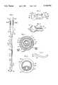
- FIG. 1is a side elevation view of a surgical instrument constructed in accordance with the present invention
- FIG. 2is a greatly enlarged view of the atraumatic tip on the surgical instrument of FIG. 1;
- FIG. 3is a greatly enlarged cross-sectional view of the atraumatic tip portion of the surgical instrument of FIG. 1 when constructed in accordance with an alternative embodiment
- FIG. 4is a cross-sectional view taken along the plane 4--4 in FIG. 1;
- FIG. 5is an alternative cross-sectional design similar to that of FIG. 4;
- FIG. 6is an alternative embodiment for the distal end of the instrument
- FIG. 8is a side elevation view of yet another embodiment of a surgical instrument constructed in accordance with the present invention.
- FIG. 9is the surgical instrument of FIG. 8 with the disposable probe assembly and flush assembly removed;
- FIG. 10is a partial cross-sectional view of the disposable flush assembly depicted in FIG. 8;
- FIG. 11is a side elevation view of the disposable probe assembly illustrated in FIG. 8;
- FIG. 12is a perspective view of an alternative probe design similar to that of FIG. 11;
- FIG. 13is a greatly enlarged cross-sectional view of the atraumatic tip portion of the disposable probe assembly of FIG. 12 with a fiber-optic assembly disposed within the probe assembly;
- FIG. 14is a greatly enlarged side elevation view of the tip of the probe assembly of FIG. 12 with a fiber-optic assembly extending within the assembly;
- FIG. 15is a side elevation view of another embodiment of a surgical instrument with the disposable probe assembly removed;
- FIG. 16is a greatly enlarged cross-sectional view taken along the plane 16--16 in FIG. 15;
- FIG. 17is a side elevation view of yet another embodiment of a surgical instrument.
- FIG. 18is a side elevation view of a fiber-optic assembly and a CCD camera head assembly in accordance with an embodiment of the invention similar to the embodiment of FIG. 17 with the probe assembly removed;
- FIG. 19is a broken view illustrating the fiber-optic assembly, the camera head assembly and means for securing together the fiber-optic assembly and the CCD camera head assembly in accordance with the embodiment of FIG. 18.
- the instrument 10comprises an elongated rigid tubular shaft 12 having a proximal end 14 and a distal end 16.
- the shaft 12includes an outer tube 18 surrounding an inner tube 20 with the inner tube 20 defining a lumen 22 extending between the proximal end 14 and the distal end 16.
- the outer tube 18terminates at 24 (FIG. 1), which is a predetermined distance proximal of the distal end 16 of the instrument 10.
- Outer tube 18 and inner tube 20provide greater rigidity to the instrument in the zone proximal of the terminus 24 of the outer tube 18.
- the outer tube 18may be formed from stainless steel.
- the rigidity provided by the coaxially disposed tubular shaft 12further enhances the tactile response of the instrument 10.
- the inner tube 20may be constructed of stainless steel or, if desired a material that is somewhat more malleable such that it is capable of being bent by the surgeon and still maintain the instrument's tactile response for use as a tactile probe.
- proximal end 14 of the shaft 12is joined to a handle 26. It is preferred that shaft 12 is generally tapered from the proximal end 14 to the distal end 16, which provides greater rigidity and further enhances tactile response of the shaft 12 at its proximal end 14.
- a segment of the inner tube 20, which is proximal of the terminus 24 of the outer tube 18,is arcuate with a bend having a desired angle in the range of from about 20 degrees up to 90 degrees, and a length in the range of from about 8 mm to 15 mm.
- Integrally formed on or otherwise affixed to the distal end 16 of the shaft 12is a rigid, atraumatic bulbous tip 28.
- the tip 28is preferably generally spherical in shape and of a size which would not tend to penetrate into the tissue being probed.
- the sphere or ball tip 28may have a diameter of about 3 mm., but that size is only indicated for the purpose of illustration.
- the desired diameter of the tip 28varies according to its intended use.
- the tip 28may have a different diameter depending on its use.
- the diameter of tip 28may be smaller than 3 mm for use in the cervical spine.
- the diameter of tip 28is expanded to be greater than the diameter of the distal end 16 to enhance tactile feedback.
- the diameter of tip 28may, however, be either greater or less than the diameter of the proximal end 14.
- the shaft 12may consists of a single tube 37.
- the tubedefines lumen 22 and extends from proximal end 14 to distal end 16, and may further form the bulbous tip 28.
- the tube 37may consists of a metal or metal alloy such as stainless steel and, if desired, be malleable.
- the tube 37 including bulbous tip 28may be constructed by methods such as hollow center grinding or turning on a screw machine.
- the tube 37is tapered such that the outer diameter at the proximal end 14 is in the range of from about 2.5 mm to 2.4 mm, and the outer diameter at the distal end 16 is in the range of from about 1.9 mm to 1.8 mm.
- the tubecan be tapered in a single area 31 with a generally uniform outer diameter from distal end 16 to 33 and from proximal end 14 to 35.
- the tube 37preferably has a smaller outer diameter between 16 and 33 than the outer diameter between 35 and 14.
- the bulbous tip 28is expanded, meaning it has an outer diameter which is greater than the outer diameter at distal end 16. However, depending on the application of the surgical instrument, the outer diameter of the bulbous tip 28 may be either greater or less than the outer diameter at proximal end 14.
- the taperingenhances the tactile response of the shaft 12 at its proximal end 14. Further, if the tube 37 is construed of malleable material, then both the outer diameter and the rigidity of the shaft 12 will decrease towards the distal end 16 of the tube 27. This allows for ease in shaping the shaft 12 about distal end 14 to position the tip 28 as desired.
- the present inventionalso contemplates other shapes for tip 28, such as the prolate or oblate tip shown in FIG. 6.
- tip 28typically, prolate tips pass through tissue easily whereas oblate tips provide better tactile response.
- the tipis preferably rigid or incompressible in order to facilitate tactile response.
- a bore 30is formed longitudinally through the handle 26 and that bore is preferably in generally coaxial alignment with the lumen 22 of the inner tube 20. Passing through the bore 30 and the lumen 22 is a fiber-optic assembly 32.
- the fiber-optic assembly 32preferably includes an outer sheath 34 surrounding an assembly of image fibers 36 and preferably at least one, or more preferably several, illumination fibers 38.
- an annular space 23is formed in the lumen 22 between inner tube 20 and sheath 34 as illustrated in FIG. 4. This space can be used to introduce a flushing fluid as discussed below.
- image fibers 36 and illumination fibers 38are not axially disposed. Instead, image fibers 36 and illumination fibers 38 are located between inner tube 20 and sheath 34. This configuration defines a space 23 having less surface area and a greater cross-section area than space 23 in FIG. 4 to provide greater conduction of fluid with less pressure.
- an irrigation fluid flow rate of about 25 cc/min.is required to clear blood away from lens 50 during a surgical procedure.
- most pressure cuffsprovide up to about 300 mm Hg pressure. Some lumen configurations may not be able to achieve that flow rate with this pressure. Space 23 of FIG. 5, however, can provide that rate with this pressure.
- a molded plastic hub member 40surrounding a junction where the illumination fibers 38 and the image fibers 36 bifurcate into separate branches.
- a connector 42which is adapted to mate with a viewing device (not shown), such as an optical eyepiece or a video camera providing a desired degree of magnification.
- the illumination fibers 38also terminate at their proximal end in a connector 44 which is adapted to connect to a light source (not shown).
- the atraumatic (ball) tip 28defines an opening 48 leading to a hollow chamber 46 formed within the tip.
- the chamberhas a diameter large enough to receive distal end 16 of the shaft.
- the chamber 46communicates with the generally circular surface opening 48 through the sphere's surface at its most distal end.
- Fiber-optic assembly 32terminates within the hollow chamber 46 and an objective lens 50 is provided at the distal end of the image fibers 36 in assembly 32.
- the arcuate bend in inner tube 20may be less than 90 degrees. As the arcuate bend in the tube 20 approaches 90 degrees, however, stress between the interface of the lens 50 and image fibers 36 is increased. To overcome this, it is preferred in the present invention to increase the distance between the arcuate bend in tube 20 and tip 28. To further lessen this stress, another bend can be located proximal to distal end 16 as illustrated in FIG. 6.
- a source of lightWhen a source of light is coupled to the connector 44, it passes through the illumination fibers 38 and out through the opening 48 in the spherical tip 28. Objects illuminated by such light reflect an image back through the objective lens 50 and the image fibers within the image bundle 36 to the viewing device (not shown) coupled to the connector 42.
- the surgeonis able to insert the instrument through a surgically created opening in the body and then by manipulating the handle can position the instrument so as to feel tissue structures of interest. Because of the incorporation of the fiber-optic assembly 32 within the instrument, the tissue structures being approached and felt with the atraumatic tip 28 can also be visually observed.
- FIG. 2depicts an end-viewing instrument
- the cross-sectional view of FIG. 3shows the manner in which the atraumatic tip can be modified to offer a side-viewing instrument.
- the bulbous or spherical tip 28 in FIG. 3is generally hollow and has an opening 52 formed therein which is at an angle, approximately 90 degrees as illustrated, to the longitudinal axis of the shaft 20.
- an optical meanssuch as a prism or mirror 54, which is positioned to refract or reflect light emanating from the ends of the illumination fibers 38 within the assembly 32 out through the opening 52.
- Prism 54picks up the reflected image observed through the opening 52 and presents it on the objective lens 50.
- the prismpreferably has a plurality of facets and a reflective surface on at least one of the facets.
- a Y-fitting 56 having a Luer lock 58 on its proximal endis joined to the handle 26 and contains a lumen that is in fluid communication with the lumen 22 in the shaft 12. This allows a source of irrigation or flushing liquid to be injected through the Luer fitting 58 and the Y-fitting 56 so that it will exit the lumen 22 of the fiber-optic assembly 32 in a fashion to insure that the objective lens 50 can be flushed clean of blood or other debris that might otherwise occlude the image being viewed.
- the irrigation fluid exiting the tip 28 of the surgical instrument 10can be used to hydrodissect soft tumors or hematomas.
- the surgeonincreases the pressure provided by the irrigation fluid source such that fluid exiting the tip 28 of the instrument 10 will have sufficient force to displace unwanted structures.
- using a fluid flow rate of about 50 milliliters per minute through the lumen 22may provide suitable pressure to dissect soft tumors in a procedure involving inter-cranial work.
- annular space defined between tubes 18 and 20, and the outer sheath 34minimizes the diameter of the shaft 12 and maximizes the possible flow rate of flushing liquid.
- Thisprovides an annular flush that spreads fluid around the circumference of fiber-optic assembly 32 of the distal end 16 and out the space 23 to insure clearness in the entire field of view of fiber-optic assembly 32.
- This same annular space or channel or, alternatively, a separate lumen or channelcan be used to aspirate fluids.
- a separate channel or lumen as shown in FIG. 5 disposed parallel to fiber-optics assembly 32can also be used for providing the flushing liquid.
- These separate lumen or channelsare preferably located within shaft 12.
- the outside diameter of the shaft member or outer tube 18may be approximately 1/8 in. and may be about 5 in. long.
- the shaft portion or outer tube 20may be about 1 in. in length and 2 mm. in diameter.
- the number of illumination fibers and their diametersare selected to provide adequate light intensity. Typically, there might be three plastic illumination fibers, each of a diameter of 250 microns. Alternatively, approximately 100 glass fibers of 50 micron diameter each might be used.
- the light emitted by the illumination fibersilluminates the tissue exterior to the tip 28 to be viewed.
- Light reflected from the tissueis collected by the objective lens 50 and focused on a preferred planar face defined by the distal ends of image fibers 36 of fiber-optic assembly 32.
- this assembly including image fibers 36may include up to 10,000 individual glass fibers which provides excellent resolution of the image focused by the objective lens 50.
- a second fiber-optic bundlemay also be routed through the handle and shaft of the instrument and have its objective lens properly positioned relative to the opening to provide a binocular view along separate optical axes.
- the surgical instrument 110includes an optics harness assembly 181 removably mounted on a probe assembly 162.
- the instrument 110also preferably includes a flush assembly 160 which can be removably mounted between the probe assembly 162 and the optics assembly 181.
- One or more of the optics harness assembly 181, probe assembly 162 and flush assembly 160can be made disposable.
- the probe assembly 162 and flush assembly 160can be steam sterilized and reused while the more delicate optics harness assembly can be disposed and replaced after use.
- the flush assembly 160includes a flexible hose 164 containing a lumen in fluid communication with the bore 166 of a Y-connector 168. Attached to the distal end of the hose 164 is fitting 156 having luer lock 158. The fitting 156 connects to a source of irrigation or flushing liquid which flows through the hose 164 and into the Y-connector bore 166.
- the Y-connector 168is detachably secured to endoscope connector 170. As illustrated by FIGS. 9 and 10, the fiber-optic assembly 132 which coaxially extends from connector 170 is inserted through the Y-connector bore 166. Likewise, tapered luer fitting 172 of connector 170 is extended into the Y-connector bore 166. Outer surface 173 of the luer fitting 172 frictionally adjoins against inner surface 174 of the Y-connector 168 to provide a tightly sealed interconnection. The seal ensures that liquid injected into the bore 166 from connector 156 will flow around the fiber-optic assembly 132 and exit only from distal open end 175 of T-connector 168.
- the disposable probe assembly 162Attached to the T-connector distal end 175 is the disposable probe assembly 162 that includes an elongated rigid shaft 112 of similar construction as that depicted in FIG. 1.
- the shaft 112includes inner tube 120 surrounded by outer tub 118 and terminating at 124.
- the proximal end 114 of the shaft 112is joined to handle 126.
- atraumatic bulbous tip 128is interconnected to the distal end 116 of the shaft 112.
- bore 130longitudinally extends through the handle 126 and is preferably in generally coaxial alignment with the lumen of the inner tube 120.
- the proximal end of the handle 126includes an opening 178 in communication with the bore 130.
- the handle 126is detachably secured to the disposable flush assembly 160 by extending the distal end 175 of the Y-connector luer fitting 180 within the bore 130 of the handle 126.
- a liquid tight sealis formed between the handle 126 and the flush assembly 160 due to the adjoining of tapered outer surface 182 of luer fitting 180 against inner wall 183 of handle 126.
- the connector 170 on the optics harness assembly 181 and handle 126can cooperate to directly mount the harness 181 with the handle 126 such that the fiber-optic assembly 132 extends through the bore 130 and lumen 122.
- the fiber-optic assembly 132has a predetermined length such that the assembly will terminate spaced from the opening 148 when the harness assembly 181 is connected to the handle 126.
- the handle 126 and the Y-connector 168are in fluid communication such that liquid flowing into the handle bore 130 from the Y-connector bore 169 will pass through the lumen 122 within shaft 112 and exit from tip 128.
- adjoining both the probe 162 and flush assembly 160 to the endoscope connector 170results in the fiber-optic assembly 132 extending within the lumen of inner tube 120 and terminating within the lumen 122.
- FIG. 8The operation of the surgical instrument depicted in FIG. 8 is similar to that of FIG. 1. However, after performing a surgical procedure, the probe assembly 162 and flush assembly 160 can be manually removed and discarded by pulling them apart from each other.
- the present inventionalso allows the disposable probe assembly 162 to be connected directly to the endoscope connector 170. As such, no flush tube assembly 160 is provided.
- the probe assembly 162is detachably coupled to connector 170 by inserting optical assembly 132 and luer fitting 173 within the opening 178 of the probe handle 126. As luer fitting 173 extends into the handle bore 130, the outer surface 173 of the luer fitting will frictionally engage against the inner wall 183 of the handle.
- adjustmentsmust be made to ensure that the terminal end of the fiber-optic assembly 132 does not extend from the tip of the probe 162.
- Such adjustmentsmay include providing either an optic assembly 132 with a shorter length or a disposable probe assembly 162 having a longer shaft length.
- FIGS. 12-14provide an alternative embodiment of a disposable probe assembly 262 wherein an elevator tip 284 extends from the distal end 216 of the shaft 212.
- shaft 212preferably consists of a single tube 237 defining lumen 222 and extending from proximal end 214 to distal end 216.
- the tube 237may consists of stainless steel and, if desired, be malleable by the surgeon such that the tube can be bent while still providing adequate tactile response or force in use.
- the harness assemblybe connected directly to the handle 226 so that the fiber-optic assembly 232 is free to move slightly within the lumen 222 as the surgeon bends the tube to the desired angle or shape. This avoids placing stress on the optic fibers to prevent breakage.
- the tube 237have a uniform outer circumference from the proximal end 214 to the distal end 216 with the proximal end 214 affixed to handle 226. Further, it is preferred that the tube 237 provides a straight length from end 214 to end 216.
- the tip 284preferably provides a blade 288 for displacing tissue structures in order to gain access to a selected area to be visually observed or flushed with irrigation fluid.
- the blade 288is preferably generally spoon or dovetailed in shape with opposing bottom surface 289 and top surface 290 areas.
- the blade 288extends from the shaft 212 such that the surface areas 289 and 290 outwardly expand and arch away from fiber-optic assembly line of sight 292.
- the terminal end 293 of the blade 288is curved to prevent the blade 288 from easily cutting or damaging tissue. Further, to increase the amount of tissue that can be moved with the blade 288, it is desired that the surface areas 289, 290 of the blade expand to a width which is greater than the outer diameter of the shaft 212.
- the blade 288integrally extends from the shaft 212 such that the distal end 216 of the tube 237 provides a tapered surface opening 248 to the lumen 222.
- a generally semicircular indentation 295which is concave and extends from the lumen 222 of the shaft 212.
- the indentation 295provides for a gradual transition from the cylindrically shaped lumen 222 within the shaft 212 to the relatively planar bottom surface area 289 of the blade 288.
- the fiber-optic assembly 232extends through the bore 230 of the handle 226 and into the lumen 222 of shaft 212.
- the fiber-optic assembly 232terminates within the lumen 222 and juxtapose to the surface opening 246 of the elevator tip 284. This allows the examined tissue to be brought into proper focus and prevent the fiber-optic assembly from coming into contact with the tissue.
- the annular space 223 formed in the lumen 222 between the tube 237 and the fiber-optic assembly 232allows for irrigation fluid to pass through the shaft 212 and exit via the surface opening 248.
- the fluidcan be used to clean the fiber-optic assembly 232 or the tissue area to be viewed.
- the surgical instrumentis inserted through an opening in the body of a patient. Then, by manipulating the handle 226, the top 290 surface of the blade 288 is pressed against tissue that obstructs the area to be examined. The blade 288 elevates, or expels, the tissue and allows unobstructed access to the desired examination area.
- the endoscope connector 70may additionally provide for the exit of irrigation fluid from the luer fitting 72.
- the fiber-optic assembly 332 and the hose 364are fused together by hub 341 into a single conduit 396 which is preferably made of flexible plastic.
- the conduit 396provides a partition 397 which separates passage 398 from the fiber-optic assembly 332.
- the passage 398extends within the conduit 396 and is in fluid communication with hose 364. This allows an irrigation solution to be injected into connector 356, pass through the connector 370, and exit from the distal end of luer fitting 372.
- the fiber-optic assembly 332is secured within the conduit 396 by an adhesive 399 such as epoxy. Further, the adhesive 399 prevents irrigation fluid from re-entering the conduit 396 once the fluid exits from passage 398.
- the endoscope connector 370provides luer fitting 372 for detachably securing a probe assembly to the connector. Once secured, the fiber-optic assembly 332 extends within the lumen of the probe assembly shaft. Further, the lumen of the probe assembly and connector passage 398 are in fluid communication with each other such that fluid provided at connector 356 will exit from the surface opening of the probe assembly.
- FIGS. 17-19illustrate a surgical instrument 410 in accordance with another alternative embodiment of the invention.
- the probe assembly 462is secured to a camera such as a Charged-Coupled Device (CCD) camera head assembly 402 by, for example, a second connector 404 extending from the fiber-optic assembly 432.
- CCDCharged-Coupled Device
- the CCD camera head assembly 402includes a casing 406, a CCD camera head 408, a CCD chip 411, and a focusing lens system 413 for focusing an image onto the CCD chip 411.
- the CCD camera head 408preferably has an outer diameter of about 1/4 inch (about 7 mm).
- the focusing lens system 413includes a focusing ring 415 and a lens 417, and a channel 419 is defined within the casing 406 to permit sliding of the lens 417 by the focusing ring 415 to bring the image into focus.
- An electric cord 421extends from the CCD camera head assembly 402 to a television monitor.
- a conduit 496extends from the second connector 404 that contains illumination fibers and, if desired, an irrigation tube.
- a proximal end of the second connector 404is removably secured to the CCD camera head assembly 402 preferably so that a distal end of an image fiber bundle 436 extending from the fiber-optic assembly 432 is a predetermined distance from the CCD camera head 408 or the focusing lens 417 so that the image can readily be brought into focus.
- a first mating portion 425 having a male thread 427is defined at the proximal end of the second connector 404.
- a second mating portion 429 having a female threadis defined at a distal end of the casing 406 of the CCD camera head assembly 402. The first mating portion 425 is adapted to extend within the casing 406 and threadingly engage the second mating portion 429.
- FIGS. 17-19provides many advantages. For example, it enables the fiber-optic assembly to be readily and easily secured adjacent the CCD camera head 408 so that the distal end of the image fiber bundle 436 and the focusing lens 417 or CCD camera head are spaced apart by a predetermined distance. Thus, the image can be readily and easily brought into focus. With this construction, the fiber-optic assembly 432 can be disposable, with the camera head assembly 402 being reusable with other fiber-optic assemblies. This is a significant advantage because CCD chips and camera heads tend to be relatively expensive components.
- the CCD camera head 408is positioned at a location that does not interfere with the surgical procedure and does not significantly affect the control and tactile feel of the instrument.
- the CCD camera headis sufficiently close to the surgical site, yet positioned so that it should not come into contact with the surgical site.
- the camera head assembly 402also preferably is compact and lightweight so that it does not add any significant bulk or weight to the surgical instrument. These embodiments also permit the CCD camera head to be heavily insulated by the casing 406 or other suitable insulation without interfering with the surgical procedure and without significantly affecting the control and tactile feel of the instrument.
Landscapes
- Health & Medical Sciences (AREA)
- Life Sciences & Earth Sciences (AREA)
- Surgery (AREA)
- Optics & Photonics (AREA)
- Physics & Mathematics (AREA)
- Biophysics (AREA)
- Biomedical Technology (AREA)
- Veterinary Medicine (AREA)
- Pathology (AREA)
- Radiology & Medical Imaging (AREA)
- Public Health (AREA)
- Engineering & Computer Science (AREA)
- Nuclear Medicine, Radiotherapy & Molecular Imaging (AREA)
- Heart & Thoracic Surgery (AREA)
- Medical Informatics (AREA)
- Molecular Biology (AREA)
- Animal Behavior & Ethology (AREA)
- General Health & Medical Sciences (AREA)
- Neurology (AREA)
- Orthopedic Medicine & Surgery (AREA)
- Endoscopes (AREA)
Abstract
Description
Claims (35)
Priority Applications (5)
| Application Number | Priority Date | Filing Date | Title |
|---|---|---|---|
| US08/638,680US5735792A (en) | 1992-11-25 | 1996-04-29 | Surgical instrument including viewing optics and an atraumatic probe |
| EP97921418AEP0904002B1 (en) | 1996-04-29 | 1997-04-25 | Surgical instrument including viewing optics and an atraumatic probe |
| AT97921418TATE274325T1 (en) | 1996-04-29 | 1997-04-25 | SURGICAL INSTRUMENT WITH VIEWING OPTICS AND ATRAAUMATIC PROBE |
| PCT/US1997/007079WO1997040739A1 (en) | 1996-04-29 | 1997-04-25 | Surgical instrument including viewing optics and an atraumatic probe |
| DE69730426TDE69730426T2 (en) | 1996-04-29 | 1997-04-25 | SURGERY INSTRUMENT WITH VIEWING OPTICS AND ATRAUMATIC PROBE |
Applications Claiming Priority (3)
| Application Number | Priority Date | Filing Date | Title |
|---|---|---|---|
| US98164192A | 1992-11-25 | 1992-11-25 | |
| US08/233,013US5512034A (en) | 1992-11-25 | 1994-04-25 | Surgical instrument including viewing optics and a ball probe |
| US08/638,680US5735792A (en) | 1992-11-25 | 1996-04-29 | Surgical instrument including viewing optics and an atraumatic probe |
Related Parent Applications (1)
| Application Number | Title | Priority Date | Filing Date |
|---|---|---|---|
| US08/233,013Continuation-In-PartUS5512034A (en) | 1992-11-25 | 1994-04-25 | Surgical instrument including viewing optics and a ball probe |
Publications (1)
| Publication Number | Publication Date |
|---|---|
| US5735792Atrue US5735792A (en) | 1998-04-07 |
Family
ID=24560999
Family Applications (1)
| Application Number | Title | Priority Date | Filing Date |
|---|---|---|---|
| US08/638,680Expired - LifetimeUS5735792A (en) | 1992-11-25 | 1996-04-29 | Surgical instrument including viewing optics and an atraumatic probe |
Country Status (5)
| Country | Link |
|---|---|
| US (1) | US5735792A (en) |
| EP (1) | EP0904002B1 (en) |
| AT (1) | ATE274325T1 (en) |
| DE (1) | DE69730426T2 (en) |
| WO (1) | WO1997040739A1 (en) |
Cited By (159)
| Publication number | Priority date | Publication date | Assignee | Title |
|---|---|---|---|---|
| US5902231A (en)* | 1996-03-22 | 1999-05-11 | Sdgi Holdings, Inc. | Devices and methods for percutaneous surgery |
| US6115523A (en)* | 1996-10-04 | 2000-09-05 | University Of Florida | Plastic optical fiber airway imaging system |
| US6152871A (en)* | 1996-03-22 | 2000-11-28 | Sdgi Holdings, Inc. | Apparatus for percutaneous surgery |
| US6162170A (en)* | 1996-03-22 | 2000-12-19 | Sdgi Holdings, Inc. | Devices and methods for percutaneous surgery |
| US6322498B1 (en)* | 1996-10-04 | 2001-11-27 | University Of Florida | Imaging scope |
| US6461349B1 (en)* | 1997-10-24 | 2002-10-08 | Carl Zeiss Meditec Ag | Medical handpiece with a light guide which can be displaced in an axial direction |
| US6503263B2 (en) | 2000-09-24 | 2003-01-07 | Medtronic, Inc. | Surgical micro-shaving instrument with elevator tip |
| US20030073998A1 (en)* | 2000-08-01 | 2003-04-17 | Endius Incorporated | Method of securing vertebrae |
| US20030078476A1 (en)* | 2001-07-24 | 2003-04-24 | Hill Stephen D. | Apparatus for intubation |
| US20030143510A1 (en)* | 2000-01-21 | 2003-07-31 | Yves Berube-Lauziere | System and method for detection of dental tartar |
| US20030191461A1 (en)* | 2000-04-07 | 2003-10-09 | Synergetics, Inc., A Corporation | Directional laser probe |
| US6679833B2 (en) | 1996-03-22 | 2004-01-20 | Sdgi Holdings, Inc. | Devices and methods for percutaneous surgery |
| WO2004026125A1 (en)* | 2002-09-19 | 2004-04-01 | Endospine Kinetics Limited | Endoscope |
| US20040106081A1 (en)* | 2001-03-21 | 2004-06-03 | Naim Karazivan | System and method for detection and removal of dental tartar |
| US20040111136A1 (en)* | 1996-08-13 | 2004-06-10 | Oratec Interventions, Inc., A Delaware Corporation | Method for treating intervertebral discs |
| US6749605B2 (en) | 1996-10-23 | 2004-06-15 | Oratec Interventions, Inc. | Catheter for delivery of energy to a surgical site |
| US20040127963A1 (en)* | 1999-01-25 | 2004-07-01 | Uchida Andy H. | Intervertebral decompression |
| US20040176763A1 (en)* | 1996-03-22 | 2004-09-09 | Foley Kevin T. | Methods for percutaneous surgery |
| US20040186346A1 (en)* | 1996-03-22 | 2004-09-23 | Smith Maurice M. | Devices and methods for percutaneous surgery |
| US20040220451A1 (en)* | 1996-10-04 | 2004-11-04 | Dietrich Gravenstein | Imaging scope |
| US6814698B2 (en) | 2001-10-05 | 2004-11-09 | Clarus Medical, Llc | Endoscope with flexible light guide having offset distal end |
| US20040249246A1 (en)* | 2003-04-22 | 2004-12-09 | Campos Jorge A. | System, apparatus, and method for viewing a visually obscured portion of a cavity |
| US20050137524A1 (en)* | 2003-12-23 | 2005-06-23 | Robert Sakal | Ductal lavage catheter having an off-axis tip |
| US20050154379A1 (en)* | 2003-01-31 | 2005-07-14 | Innovatech Surgical, Inc. | Adjustable laser probe for use in vitreoretinal surgery |
| US20050182297A1 (en)* | 1996-10-04 | 2005-08-18 | Dietrich Gravenstein | Imaging scope |
| US20050181333A1 (en)* | 2002-05-08 | 2005-08-18 | Naim Karazivan | System and method for detecting dental caries |
| US20060015093A1 (en)* | 2003-01-04 | 2006-01-19 | Endocare, Inc. | Open system heat exchange catheters and methods of use |
| US20060025650A1 (en)* | 2002-10-03 | 2006-02-02 | Oren Gavriely | Tube for inspecting internal organs of a body |
| US20060095059A1 (en)* | 2004-10-15 | 2006-05-04 | Baxano, Inc. | Devices and methods for tissue modification |
| US20060135882A1 (en)* | 2004-10-15 | 2006-06-22 | Baxano, Inc. | Devices and methods for selective surgical removal of tissue |
| US20060241648A1 (en)* | 2005-02-04 | 2006-10-26 | Bleich Jeffery L | Methods and apparatus for tissue modification |
| US20060241350A1 (en)* | 2005-04-22 | 2006-10-26 | Sdgi Holdings, Inc. | Instruments and methods for selective tissue retraction through a retractor sleeve |
| WO2006130730A2 (en) | 2005-06-01 | 2006-12-07 | Cannuflow, Inc. | Protective cap for arthroscopic instruments |
| EP1776917A1 (en)* | 2005-10-18 | 2007-04-25 | Karl Storz GmbH & Co. KG | Endoscope |
| US20070189968A1 (en)* | 1999-06-11 | 2007-08-16 | Annette Bianchi | Gel composition for filling a breast milk duct prior to surgical excision of the duct or other breast tissue |
| US20070213734A1 (en)* | 2006-03-13 | 2007-09-13 | Bleich Jeffery L | Tissue modification barrier devices and methods |
| US20070213733A1 (en)* | 2004-10-15 | 2007-09-13 | Bleich Jeffery L | Mechanical tissue modification devices and methods |
| US20080051812A1 (en)* | 2006-08-01 | 2008-02-28 | Baxano, Inc. | Multi-Wire Tissue Cutter |
| US20080086114A1 (en)* | 2006-08-29 | 2008-04-10 | Baxano, Inc. | Tissue Access Guidewire System and Method |
| US20080106777A1 (en)* | 2006-11-03 | 2008-05-08 | Weir Michael P | Resonant fourier scanning |
| US20080146898A1 (en)* | 2006-12-19 | 2008-06-19 | Ethicon Endo-Surgery, Inc. | Spectral windows for surgical treatment through intervening fluids |
| US20080226029A1 (en)* | 2007-03-12 | 2008-09-18 | Weir Michael P | Medical device including scanned beam unit for imaging and therapy |
| DE102008018932A1 (en) | 2007-04-17 | 2008-11-20 | C2Cure Inc., Wilmington | Imaging systems and methods, in particular for use with an instrument used in open surgery |
| US20080287938A1 (en)* | 2005-08-11 | 2008-11-20 | Synergetics, Inc. | Illuminated Directional Laser Probe |
| US20090015695A1 (en)* | 2007-07-13 | 2009-01-15 | Ethicon Endo-Surgery, Inc. | Sbi motion artifact removal apparatus and method |
| WO2009024107A1 (en)* | 2007-08-23 | 2009-02-26 | Polydiagnost Entwicklungs-, Produktions-, Vertriebs-, Und Service Gesellschaft Mbh | Modular endoscope |
| US20090062837A1 (en)* | 2007-08-29 | 2009-03-05 | Christoph Gasche | Outer tube for natural orifice surgery |
| US20090182478A1 (en)* | 2008-01-15 | 2009-07-16 | Gm Global Technology Operations, Inc. | Axle torque based cruise control |
| US7578819B2 (en) | 2005-05-16 | 2009-08-25 | Baxano, Inc. | Spinal access and neural localization |
| US7589316B2 (en) | 2007-01-18 | 2009-09-15 | Ethicon Endo-Surgery, Inc. | Scanning beam imaging with adjustable detector sensitivity or gain |
| US20090264703A1 (en)* | 2008-04-21 | 2009-10-22 | Tyco Healthcare Group Lp | Endoscopic cleaner |
| US20090326525A1 (en)* | 2008-06-26 | 2009-12-31 | Jessica Hixon | Laser fiber capillary apparatus and method |
| US7713265B2 (en) | 2006-12-22 | 2010-05-11 | Ethicon Endo-Surgery, Inc. | Apparatus and method for medically treating a tattoo |
| US7738969B2 (en) | 2004-10-15 | 2010-06-15 | Baxano, Inc. | Devices and methods for selective surgical removal of tissue |
| US20100280317A1 (en)* | 2009-04-03 | 2010-11-04 | Silvestrini Thomas A | Ocular implant delivery systems and methods |
| US20110077525A1 (en)* | 2009-05-07 | 2011-03-31 | Aloka Co., Ltd. | Ultrasound Systems and Methods For Orthopedic Applications |
| US7925333B2 (en) | 2007-08-28 | 2011-04-12 | Ethicon Endo-Surgery, Inc. | Medical device including scanned beam unit with operational control features |
| US20110087257A1 (en)* | 2009-04-02 | 2011-04-14 | Spine View, Inc. | Minimally invasive discectomy |
| US7938830B2 (en) | 2004-10-15 | 2011-05-10 | Baxano, Inc. | Powered tissue modification devices and methods |
| US7959577B2 (en) | 2007-09-06 | 2011-06-14 | Baxano, Inc. | Method, system, and apparatus for neural localization |
| US20110152952A1 (en)* | 2009-12-17 | 2011-06-23 | Custom Spine, Inc. | Surgical Implant Insertion Apparatus and Method |
| US7983739B2 (en) | 2007-08-27 | 2011-07-19 | Ethicon Endo-Surgery, Inc. | Position tracking and control for a scanning assembly |
| US7985247B2 (en) | 2000-08-01 | 2011-07-26 | Zimmer Spine, Inc. | Methods and apparatuses for treating the spine through an access device |
| US7995045B2 (en) | 2007-04-13 | 2011-08-09 | Ethicon Endo-Surgery, Inc. | Combined SBI and conventional image processor |
| US20110208062A1 (en)* | 2009-05-07 | 2011-08-25 | Aloka Company, Ltd. | Ultrasound Systems and Methods For Orthopedic Applications |
| US8048080B2 (en) | 2004-10-15 | 2011-11-01 | Baxano, Inc. | Flexible tissue rasp |
| US8050520B2 (en) | 2008-03-27 | 2011-11-01 | Ethicon Endo-Surgery, Inc. | Method for creating a pixel image from sampled data of a scanned beam imager |
| US8062300B2 (en) | 2006-05-04 | 2011-11-22 | Baxano, Inc. | Tissue removal with at least partially flexible devices |
| US8062298B2 (en) | 2005-10-15 | 2011-11-22 | Baxano, Inc. | Flexible tissue removal devices and methods |
| US8092456B2 (en) | 2005-10-15 | 2012-01-10 | Baxano, Inc. | Multiple pathways for spinal nerve root decompression from a single access point |
| US8160678B2 (en) | 2007-06-18 | 2012-04-17 | Ethicon Endo-Surgery, Inc. | Methods and devices for repairing damaged or diseased tissue using a scanning beam assembly |
| EP2446825A1 (en)* | 2010-10-28 | 2012-05-02 | Hitachi Aloka Medical, Ltd. | Tissue insertion type ultrasonic probe |
| EP2446824A1 (en)* | 2010-10-28 | 2012-05-02 | Hitachi Aloka Medical, Ltd. | Tissue insertion type ultrasonic probe |
| US20120116403A1 (en)* | 2002-09-27 | 2012-05-10 | Surgitech, Llc | Surgical file system |
| US8192436B2 (en) | 2007-12-07 | 2012-06-05 | Baxano, Inc. | Tissue modification devices |
| US8216214B2 (en) | 2007-03-12 | 2012-07-10 | Ethicon Endo-Surgery, Inc. | Power modulation of a scanning beam for imaging, therapy, and/or diagnosis |
| US8221397B2 (en) | 2004-10-15 | 2012-07-17 | Baxano, Inc. | Devices and methods for tissue modification |
| US8257356B2 (en) | 2004-10-15 | 2012-09-04 | Baxano, Inc. | Guidewire exchange systems to treat spinal stenosis |
| US8273015B2 (en) | 2007-01-09 | 2012-09-25 | Ethicon Endo-Surgery, Inc. | Methods for imaging the anatomy with an anatomically secured scanner assembly |
| US20120259173A1 (en)* | 2011-04-05 | 2012-10-11 | Nellcor Puritan Bennett Llc | Visualization device and holder for use with a tracheal tube |
| US8332014B2 (en) | 2008-04-25 | 2012-12-11 | Ethicon Endo-Surgery, Inc. | Scanned beam device and method using same which measures the reflectance of patient tissue |
| US8366712B2 (en) | 2005-10-15 | 2013-02-05 | Baxano, Inc. | Multiple pathways for spinal nerve root decompression from a single access point |
| US20130046139A1 (en)* | 2011-08-19 | 2013-02-21 | Harold I. Daily | Hysteroscopes with curved tips |
| US8394102B2 (en) | 2009-06-25 | 2013-03-12 | Baxano, Inc. | Surgical tools for treatment of spinal stenosis |
| US8398641B2 (en) | 2008-07-01 | 2013-03-19 | Baxano, Inc. | Tissue modification devices and methods |
| US8409206B2 (en) | 2008-07-01 | 2013-04-02 | Baxano, Inc. | Tissue modification devices and methods |
| US8414484B2 (en) | 2009-12-17 | 2013-04-09 | Custom Spine, Inc. | Percutaneous tube assembly |
| US20130204083A1 (en)* | 2012-02-03 | 2013-08-08 | Arthrex, Inc. | Sheathless arthroscope and system |
| US8540746B2 (en) | 1998-08-20 | 2013-09-24 | Zimmer Spine, Inc. | Cannula for receiving surgical instruments |
| US8568416B2 (en) | 2004-10-15 | 2013-10-29 | Baxano Surgical, Inc. | Access and tissue modification systems and methods |
| US8613745B2 (en) | 2004-10-15 | 2013-12-24 | Baxano Surgical, Inc. | Methods, systems and devices for carpal tunnel release |
| US8626271B2 (en) | 2007-04-13 | 2014-01-07 | Ethicon Endo-Surgery, Inc. | System and method using fluorescence to examine within a patient's anatomy |
| US20140055283A1 (en)* | 2011-08-01 | 2014-02-27 | Greenwave Reality, Pte Ltd. | Multiple and interchangeable meter reading probes |
| US8690764B2 (en) | 2010-10-20 | 2014-04-08 | Covidien Lp | Endoscope cleaner |
| US8801606B2 (en) | 2007-01-09 | 2014-08-12 | Ethicon Endo-Surgery, Inc. | Method of in vivo monitoring using an imaging system including scanned beam imaging unit |
| US8801626B2 (en) | 2004-10-15 | 2014-08-12 | Baxano Surgical, Inc. | Flexible neural localization devices and methods |
| US8845639B2 (en) | 2008-07-14 | 2014-09-30 | Baxano Surgical, Inc. | Tissue modification devices |
| US20140316194A1 (en)* | 2013-04-19 | 2014-10-23 | Henke-Sass, Wolf Gmbh | Endoscope with a rigid curved shaft as well as process for producing such an endoscope |
| US20150087911A1 (en)* | 2013-09-26 | 2015-03-26 | Gyrus Acmi, Inc. D.B.A Olympus Surgical Technologies America | Endoscope sheath deflection devices |
| US20150126808A1 (en)* | 2011-05-18 | 2015-05-07 | Centre Hospitalier Universitaire De Bordeaux (C.H.U. De Bordeaux) | Method for positioning a disposable sterile endotracheal tube, and corresponding system for intubation |
| US9079762B2 (en) | 2006-09-22 | 2015-07-14 | Ethicon Endo-Surgery, Inc. | Micro-electromechanical device |
| US9101386B2 (en) | 2004-10-15 | 2015-08-11 | Amendia, Inc. | Devices and methods for treating tissue |
| US9125552B2 (en) | 2007-07-31 | 2015-09-08 | Ethicon Endo-Surgery, Inc. | Optical scanning module and means for attaching the module to medical instruments for introducing the module into the anatomy |
| US9247952B2 (en) | 2004-10-15 | 2016-02-02 | Amendia, Inc. | Devices and methods for tissue access |
| US9314253B2 (en) | 2008-07-01 | 2016-04-19 | Amendia, Inc. | Tissue modification devices and methods |
| US9370295B2 (en) | 2014-01-13 | 2016-06-21 | Trice Medical, Inc. | Fully integrated, disposable tissue visualization device |
| US9456829B2 (en) | 2004-10-15 | 2016-10-04 | Amendia, Inc. | Powered tissue modification devices and methods |
| EP3000492B1 (en) | 2007-10-08 | 2017-03-22 | Ais Gmbh Aachen Innovative Solutions | Catheter device |
| US20170086664A1 (en)* | 2011-05-18 | 2017-03-30 | Centre Hospitalier Universitaire De Bordeaux (C.H.U De Bordeaux) | Method for positioning a disposable sterile endotracheal tube, and corresponding system for intubation |
| US9763567B2 (en) | 2010-10-20 | 2017-09-19 | Covidien Lp | Endoscope wiper blade cleaner |
| US9924979B2 (en) | 2014-09-09 | 2018-03-27 | Medos International Sarl | Proximal-end securement of a minimally invasive working channel |
| US20180092625A1 (en)* | 2014-11-26 | 2018-04-05 | Visura Technologies, LLC | Apparatus, systems and methods for proper transesophageal echocardiography probe positioning by using camera for ultrasound imaging |
| US9980737B2 (en) | 2014-08-04 | 2018-05-29 | Medos International Sarl | Flexible transport auger |
| US10022200B2 (en) | 2014-08-25 | 2018-07-17 | Peregrine Surgical, Ltd | Microsurgical instrument |
| US10045686B2 (en) | 2008-11-12 | 2018-08-14 | Trice Medical, Inc. | Tissue visualization and modification device |
| US10111712B2 (en) | 2014-09-09 | 2018-10-30 | Medos International Sarl | Proximal-end securement of a minimally invasive working channel |
| US10117564B2 (en) | 2010-04-16 | 2018-11-06 | Hitachi Healthcare Americas Corporation | Ultrasound and detachable instrument for procedures |
| US10149602B2 (en) | 2011-07-11 | 2018-12-11 | Ambu A/S | Endobronchial tube with integrated image sensor and a cleaning nozzle arrangement |
| CN109222892A (en)* | 2017-07-11 | 2019-01-18 | 株式会社日立制作所 | Optoacoustic type conduit system and optoacoustic type conduit control method |
| US10245402B2 (en) | 2011-07-11 | 2019-04-02 | Ambu A/S | Endobronchial tube with integrated image sensor |
| US10264959B2 (en) | 2014-09-09 | 2019-04-23 | Medos International Sarl | Proximal-end securement of a minimally invasive working channel |
| US10265046B2 (en) | 2014-11-26 | 2019-04-23 | Visura Technologies, Inc. | Apparatus, system and methods for proper transesophageal echocardiography probe positioning by using camera for ultrasound imaging |
| US10299838B2 (en) | 2016-02-05 | 2019-05-28 | Medos International Sarl | Method and instruments for interbody fusion and posterior fixation through a single incision |
| US10342579B2 (en) | 2014-01-13 | 2019-07-09 | Trice Medical, Inc. | Fully integrated, disposable tissue visualization device |
| US10405886B2 (en) | 2015-08-11 | 2019-09-10 | Trice Medical, Inc. | Fully integrated, disposable tissue visualization device |
| US10449276B2 (en) | 2007-10-08 | 2019-10-22 | Ais Gmbh Aachen Innovative Solutions | Catheter device |
| US10595710B2 (en)* | 2001-10-19 | 2020-03-24 | Visionscope Technologies Llc | Portable imaging system employing a miniature endoscope |
| US10682130B2 (en) | 2015-09-04 | 2020-06-16 | Medos International Sarl | Surgical access port stabilization |
| US10786264B2 (en) | 2015-03-31 | 2020-09-29 | Medos International Sarl | Percutaneous disc clearing device |
| US10842368B2 (en) | 2016-06-10 | 2020-11-24 | Ambu A/S | Suction catheter with brush and method of use for lens cleaning |
| US10874783B2 (en) | 2007-10-08 | 2020-12-29 | Ais Gmbh Aachen Innovative Solutions | Catheter device |
| USRE48534E1 (en) | 2012-04-16 | 2021-04-27 | DePuy Synthes Products, Inc. | Detachable dilator blade |
| US11013530B2 (en) | 2019-03-08 | 2021-05-25 | Medos International Sarl | Surface features for device retention |
| US11045324B2 (en) | 2006-12-08 | 2021-06-29 | DePuy Synthes Products, Inc. | Method of implanting a curable implant material |
| US11051862B2 (en) | 2001-11-03 | 2021-07-06 | DePuy Synthes Products, Inc. | Device for straightening and stabilizing the vertebral column |
| US11096569B2 (en)* | 2014-10-15 | 2021-08-24 | Covidien Lp | Endoscope with a multiple diameter working section |
| US11129727B2 (en) | 2019-03-29 | 2021-09-28 | Medos International Sari | Inflatable non-distracting intervertebral implants and related methods |
| US11134987B2 (en) | 2011-10-27 | 2021-10-05 | DePuy Synthes Products, Inc. | Method and devices for a sub-splenius/supra-levator scapulae surgical access technique |
| US11219439B2 (en) | 2012-09-26 | 2022-01-11 | DePuy Synthes Products, Inc. | NIR/RED light for lateral neuroprotection |
| US11241252B2 (en) | 2019-03-22 | 2022-02-08 | Medos International Sarl | Skin foundation access portal |
| US11357542B2 (en) | 2019-06-21 | 2022-06-14 | Covidien Lp | Valve assembly and retainer for surgical access assembly |
| US11412921B2 (en) | 2018-10-02 | 2022-08-16 | Covidien Lp | Multi lumen access device |
| US11439380B2 (en) | 2015-09-04 | 2022-09-13 | Medos International Sarl | Surgical instrument connectors and related methods |
| US11478151B2 (en) | 2011-12-14 | 2022-10-25 | The Trustees Of The University Of Pennsylvania | Fiber optic flow and oxygenation monitoring using diffuse correlation and reflectance |
| US11484189B2 (en) | 2001-10-19 | 2022-11-01 | Visionscope Technologies Llc | Portable imaging system employing a miniature endoscope |
| US11547446B2 (en) | 2014-01-13 | 2023-01-10 | Trice Medical, Inc. | Fully integrated, disposable tissue visualization device |
| US11559328B2 (en) | 2015-09-04 | 2023-01-24 | Medos International Sarl | Multi-shield spinal access system |
| US11622753B2 (en) | 2018-03-29 | 2023-04-11 | Trice Medical, Inc. | Fully integrated endoscope with biopsy capabilities and methods of use |
| US11660082B2 (en) | 2011-11-01 | 2023-05-30 | DePuy Synthes Products, Inc. | Dilation system |
| US11672562B2 (en) | 2015-09-04 | 2023-06-13 | Medos International Sarl | Multi-shield spinal access system |
| US11737743B2 (en) | 2007-10-05 | 2023-08-29 | DePuy Synthes Products, Inc. | Dilation system and method of using the same |
| US11744447B2 (en) | 2015-09-04 | 2023-09-05 | Medos International | Surgical visualization systems and related methods |
| US11771517B2 (en) | 2021-03-12 | 2023-10-03 | Medos International Sarl | Camera position indication systems and methods |
| US11813026B2 (en) | 2019-04-05 | 2023-11-14 | Medos International Sarl | Systems, devices, and methods for providing surgical trajectory guidance |
| US11850106B2 (en) | 2020-05-06 | 2023-12-26 | Covidien Lp | Cleaning cap for a surgical access device |
| US12035889B2 (en) | 2008-07-22 | 2024-07-16 | Trice Medical, Inc. | Tissue modification devices and methods of using the same |
| US12150636B2 (en) | 2015-09-04 | 2024-11-26 | Medos International Sárl | Surgical instrument connectors and related methods |
| US12357159B2 (en) | 2019-09-27 | 2025-07-15 | The Government of the United States, as represented by the Director of the Defense Health Agency | Surgical scope with removable lumen |
| US12426868B2 (en) | 2007-09-28 | 2025-09-30 | DePuy Synthes Products, Inc. | Balloon with shape control for spinal procedures |
Families Citing this family (7)
| Publication number | Priority date | Publication date | Assignee | Title |
|---|---|---|---|---|
| DE10118944B4 (en) | 2001-04-18 | 2013-01-31 | Merit Medical Systems, Inc. | Removable, essentially cylindrical implants |
| US20040093056A1 (en) | 2002-10-26 | 2004-05-13 | Johnson Lianw M. | Medical appliance delivery apparatus and method of use |
| US7637934B2 (en) | 2003-03-31 | 2009-12-29 | Merit Medical Systems, Inc. | Medical appliance optical delivery and deployment apparatus and method |
| DE20306541U1 (en) | 2003-04-25 | 2003-06-26 | asap endoscopic products GmbH, 79108 Freiburg | endoscope |
| US7604660B2 (en) | 2003-05-01 | 2009-10-20 | Merit Medical Systems, Inc. | Bifurcated medical appliance delivery apparatus and method |
| AU2004263171B2 (en) | 2003-08-07 | 2008-12-04 | Merit Medical Systems, Inc. | Therapeutic medical appliance, delivery and method of use |
| DE102020133405A1 (en) | 2020-12-14 | 2022-06-15 | Ambu A/S | Endoscope with connector |
Citations (12)
| Publication number | Priority date | Publication date | Assignee | Title |
|---|---|---|---|---|
| US2076741A (en)* | 1935-04-09 | 1937-04-13 | American Cystoscope Makers Inc | Fenestrated endoscopic tube |
| US3799150A (en)* | 1970-12-05 | 1974-03-26 | L Bonnet | Endoscopes |
| US4793326A (en)* | 1986-12-08 | 1988-12-27 | Olympus Optical Co., Ltd. | Endoscope having insertion end guide means |
| US4802461A (en)* | 1987-08-26 | 1989-02-07 | Candela Laser Corporation | Rigid endoscope with flexible tip |
| US4867138A (en)* | 1987-05-13 | 1989-09-19 | Olympus Optical Co., Ltd. | Rigid electronic endoscope |
| US5156604A (en)* | 1990-10-25 | 1992-10-20 | Messerschmitt-Bolkow-Blohm Gmbh | Small probing hook for arthroscopy |
| US5158086A (en)* | 1990-07-20 | 1992-10-27 | W. L. Gore & Associates, Inc. | Invasive probe system |
| US5230621A (en)* | 1991-12-26 | 1993-07-27 | Bennett Jacoby | Endoscopic method and device for subgingival dental procedures |
| US5263928A (en)* | 1991-06-14 | 1993-11-23 | Baxter International Inc. | Catheter and endoscope assembly and method of use |
| US5337735A (en)* | 1992-12-28 | 1994-08-16 | Albert Salerno | Fiber-lighted stylet |
| US5505686A (en)* | 1994-05-05 | 1996-04-09 | Imagyn Medical, Inc. | Endoscope with protruding member and method of utilizing the same |
| US5512034A (en)* | 1992-11-25 | 1996-04-30 | Finn; Miles A. | Surgical instrument including viewing optics and a ball probe |
Family Cites Families (5)
| Publication number | Priority date | Publication date | Assignee | Title |
|---|---|---|---|---|
| GB2147210B (en) | 1983-09-28 | 1986-12-17 | Wolf Gmbh Richard | An endoscope |
| FR2640389B1 (en)* | 1988-12-12 | 1992-10-02 | Fibres Optiques Rech Technolo | RIGID VIDEO ENDOSCOPES |
| DE3941108C1 (en)* | 1989-12-13 | 1991-06-27 | Richard Wolf Gmbh, 7134 Knittlingen, De | |
| US5437660A (en)* | 1991-12-30 | 1995-08-01 | Trimedyne, Inc. | Tissue ablation and a lateral-lasing fiber optic device therefor |
| AU3955295A (en)* | 1994-10-13 | 1996-05-06 | Femrx | Method and device for tissue resection |
- 1996
- 1996-04-29USUS08/638,680patent/US5735792A/ennot_activeExpired - Lifetime
- 1997
- 1997-04-25DEDE69730426Tpatent/DE69730426T2/ennot_activeExpired - Lifetime
- 1997-04-25EPEP97921418Apatent/EP0904002B1/ennot_activeExpired - Lifetime
- 1997-04-25WOPCT/US1997/007079patent/WO1997040739A1/enactiveIP Right Grant
- 1997-04-25ATAT97921418Tpatent/ATE274325T1/ennot_activeIP Right Cessation
Patent Citations (12)
| Publication number | Priority date | Publication date | Assignee | Title |
|---|---|---|---|---|
| US2076741A (en)* | 1935-04-09 | 1937-04-13 | American Cystoscope Makers Inc | Fenestrated endoscopic tube |
| US3799150A (en)* | 1970-12-05 | 1974-03-26 | L Bonnet | Endoscopes |
| US4793326A (en)* | 1986-12-08 | 1988-12-27 | Olympus Optical Co., Ltd. | Endoscope having insertion end guide means |
| US4867138A (en)* | 1987-05-13 | 1989-09-19 | Olympus Optical Co., Ltd. | Rigid electronic endoscope |
| US4802461A (en)* | 1987-08-26 | 1989-02-07 | Candela Laser Corporation | Rigid endoscope with flexible tip |
| US5158086A (en)* | 1990-07-20 | 1992-10-27 | W. L. Gore & Associates, Inc. | Invasive probe system |
| US5156604A (en)* | 1990-10-25 | 1992-10-20 | Messerschmitt-Bolkow-Blohm Gmbh | Small probing hook for arthroscopy |
| US5263928A (en)* | 1991-06-14 | 1993-11-23 | Baxter International Inc. | Catheter and endoscope assembly and method of use |
| US5230621A (en)* | 1991-12-26 | 1993-07-27 | Bennett Jacoby | Endoscopic method and device for subgingival dental procedures |
| US5512034A (en)* | 1992-11-25 | 1996-04-30 | Finn; Miles A. | Surgical instrument including viewing optics and a ball probe |
| US5337735A (en)* | 1992-12-28 | 1994-08-16 | Albert Salerno | Fiber-lighted stylet |
| US5505686A (en)* | 1994-05-05 | 1996-04-09 | Imagyn Medical, Inc. | Endoscope with protruding member and method of utilizing the same |
Cited By (332)
| Publication number | Priority date | Publication date | Assignee | Title |
|---|---|---|---|---|
| US20040176763A1 (en)* | 1996-03-22 | 2004-09-09 | Foley Kevin T. | Methods for percutaneous surgery |
| US6425859B1 (en) | 1996-03-22 | 2002-07-30 | Sdgi Holdings, Inc. | Cannula and a retractor for percutaneous surgery |
| US20040186346A1 (en)* | 1996-03-22 | 2004-09-23 | Smith Maurice M. | Devices and methods for percutaneous surgery |
| US6152871A (en)* | 1996-03-22 | 2000-11-28 | Sdgi Holdings, Inc. | Apparatus for percutaneous surgery |
| US6162170A (en)* | 1996-03-22 | 2000-12-19 | Sdgi Holdings, Inc. | Devices and methods for percutaneous surgery |
| US6176823B1 (en) | 1996-03-22 | 2001-01-23 | Sdgi Holdings, Inc. | Fixture for supporting a viewing element within a cannula |
| US5954635A (en)* | 1996-03-22 | 1999-09-21 | Sdgi Holdings Inc. | Devices and methods for percutaneous surgery |
| US6206822B1 (en) | 1996-03-22 | 2001-03-27 | Sdgi Holdings, Inc. | Devices and methods for percutaneous surgery |
| US7198598B2 (en) | 1996-03-22 | 2007-04-03 | Warsaw Orthopedic, Inc. | Devices and methods for percutaneous surgery |
| US6217509B1 (en) | 1996-03-22 | 2001-04-17 | Sdgi Holdings, Inc. | Devices and methods for percutaneous surgery |
| US7993378B2 (en) | 1996-03-22 | 2011-08-09 | Warsaw Orthopedic, IN. | Methods for percutaneous spinal surgery |
| US5902231A (en)* | 1996-03-22 | 1999-05-11 | Sdgi Holdings, Inc. | Devices and methods for percutaneous surgery |
| US6520907B1 (en) | 1996-03-22 | 2003-02-18 | Sdgi Holdings, Inc. | Methods for accessing the spinal column |
| US20070156020A1 (en)* | 1996-03-22 | 2007-07-05 | Foley Kevin T | Methods for percutaneous spinal surgery |
| US6679833B2 (en) | 1996-03-22 | 2004-01-20 | Sdgi Holdings, Inc. | Devices and methods for percutaneous surgery |
| US20030139648A1 (en)* | 1996-03-22 | 2003-07-24 | Foley Kevin Thomas | Devices and methods for percutaneous surgery |
| US7647123B2 (en) | 1996-08-13 | 2010-01-12 | Oratec Interventions, Inc. | Method for treating intervertebral discs |
| US7267683B2 (en) | 1996-08-13 | 2007-09-11 | Oratec Interventions, Inc. | Method for treating intervertebral discs |
| US7282061B2 (en) | 1996-08-13 | 2007-10-16 | Oratec Interventions, Inc. | Method of treating intervertebral disc |
| US7400930B2 (en) | 1996-08-13 | 2008-07-15 | Oratec Interventions, Inc. | Method for treating intervertebral discs |
| US6997941B2 (en) | 1996-08-13 | 2006-02-14 | Oratec Interventions, Inc. | Method and apparatus for treating annular fissures in intervertebral discs |
| US20040111136A1 (en)* | 1996-08-13 | 2004-06-10 | Oratec Interventions, Inc., A Delaware Corporation | Method for treating intervertebral discs |
| US8187312B2 (en) | 1996-08-13 | 2012-05-29 | Neurotherm, Inc. | Method for treating intervertebral disc |
| US8226697B2 (en) | 1996-08-13 | 2012-07-24 | Neurotherm, Inc. | Method for treating intervertebral disc |
| US20050182297A1 (en)* | 1996-10-04 | 2005-08-18 | Dietrich Gravenstein | Imaging scope |
| US6115523A (en)* | 1996-10-04 | 2000-09-05 | University Of Florida | Plastic optical fiber airway imaging system |
| US20040220451A1 (en)* | 1996-10-04 | 2004-11-04 | Dietrich Gravenstein | Imaging scope |
| US6322498B1 (en)* | 1996-10-04 | 2001-11-27 | University Of Florida | Imaging scope |
| US7309336B2 (en) | 1996-10-23 | 2007-12-18 | Oratec Interventions, Inc. | Catheter for delivery of energy to a surgical site |
| US6749605B2 (en) | 1996-10-23 | 2004-06-15 | Oratec Interventions, Inc. | Catheter for delivery of energy to a surgical site |
| US20050149011A1 (en)* | 1996-10-23 | 2005-07-07 | Oratec Interventions, Inc. | Catheter for delivery of energy to a surgical site |
| US6461349B1 (en)* | 1997-10-24 | 2002-10-08 | Carl Zeiss Meditec Ag | Medical handpiece with a light guide which can be displaced in an axial direction |
| US8540746B2 (en) | 1998-08-20 | 2013-09-24 | Zimmer Spine, Inc. | Cannula for receiving surgical instruments |
| US20040127963A1 (en)* | 1999-01-25 | 2004-07-01 | Uchida Andy H. | Intervertebral decompression |
| US7449019B2 (en) | 1999-01-25 | 2008-11-11 | Smith & Nephew, Inc. | Intervertebral decompression |
| US20070189968A1 (en)* | 1999-06-11 | 2007-08-16 | Annette Bianchi | Gel composition for filling a breast milk duct prior to surgical excision of the duct or other breast tissue |
| US20110200695A1 (en)* | 1999-06-11 | 2011-08-18 | Annette Bianchi | Gel composition for filling a breast milk duct prior to surgical excision of the duct or other breast tissue |
| US8297971B2 (en) | 2000-01-21 | 2012-10-30 | Dentsply Canada Ltd. | System for the detection of dental artefacts |
| US7862335B2 (en) | 2000-01-21 | 2011-01-04 | Dentsply Canada Ltd. | System and method for detection of dental tartar |
| US20110165534A1 (en)* | 2000-01-21 | 2011-07-07 | Dentsply Canada Ltd | System and method for detection of dental tartar |
| US20030143510A1 (en)* | 2000-01-21 | 2003-07-31 | Yves Berube-Lauziere | System and method for detection of dental tartar |
| US20030191461A1 (en)* | 2000-04-07 | 2003-10-09 | Synergetics, Inc., A Corporation | Directional laser probe |
| US6984230B2 (en)* | 2000-04-07 | 2006-01-10 | Synergetics, Inc. | Directional laser probe |
| US20060173448A1 (en)* | 2000-04-07 | 2006-08-03 | Scheller Gregg D | Directional laser probe |
| US7473249B2 (en) | 2000-04-07 | 2009-01-06 | Synergetics, Inc. | Directional laser probe |
| US7402158B2 (en) | 2000-04-07 | 2008-07-22 | Synergetics, Inc. | Directional laser probe |
| US20060004348A1 (en)* | 2000-04-07 | 2006-01-05 | Scheller Gregg D | Directional laser probe |
| US7722530B2 (en) | 2000-08-01 | 2010-05-25 | Zimmer Spine, Inc. | Method of securing vertebrae |
| US9101353B2 (en) | 2000-08-01 | 2015-08-11 | Zimmer Spine, Inc. | Method of securing vertebrae |
| US9622735B2 (en) | 2000-08-01 | 2017-04-18 | Zimmer Spine, Inc. | Method for securing vertebrae |
| US20030073998A1 (en)* | 2000-08-01 | 2003-04-17 | Endius Incorporated | Method of securing vertebrae |
| US7056321B2 (en) | 2000-08-01 | 2006-06-06 | Endius, Incorporated | Method of securing vertebrae |
| US8277486B2 (en) | 2000-08-01 | 2012-10-02 | Zimmer Spine, Inc. | System for performing a procedure at a spinal location |
| US7985247B2 (en) | 2000-08-01 | 2011-07-26 | Zimmer Spine, Inc. | Methods and apparatuses for treating the spine through an access device |
| US7699877B2 (en) | 2000-08-01 | 2010-04-20 | Zimmer Spine, Inc. | Method of securing vertebrae |
| US8864785B2 (en) | 2000-08-01 | 2014-10-21 | Zimmer Spine, Inc. | Method for securing vertebrae |
| US7850695B2 (en) | 2000-08-01 | 2010-12-14 | Zimmer Spine, Inc. | Method of securing vertebrae |
| US8777997B2 (en) | 2000-08-01 | 2014-07-15 | Zimmer Spine, Inc. | Method for securing vertebrae |
| US6503263B2 (en) | 2000-09-24 | 2003-01-07 | Medtronic, Inc. | Surgical micro-shaving instrument with elevator tip |
| US20040106081A1 (en)* | 2001-03-21 | 2004-06-03 | Naim Karazivan | System and method for detection and removal of dental tartar |
| US8721327B2 (en) | 2001-03-21 | 2014-05-13 | Dentsply Canada Ltd. | System and method for detection and removal of dental tartar |
| US20030078476A1 (en)* | 2001-07-24 | 2003-04-24 | Hill Stephen D. | Apparatus for intubation |
| US6929600B2 (en) | 2001-07-24 | 2005-08-16 | Stephen D. Hill | Apparatus for intubation |
| US6814698B2 (en) | 2001-10-05 | 2004-11-09 | Clarus Medical, Llc | Endoscope with flexible light guide having offset distal end |
| US11484189B2 (en) | 2001-10-19 | 2022-11-01 | Visionscope Technologies Llc | Portable imaging system employing a miniature endoscope |
| US10595710B2 (en)* | 2001-10-19 | 2020-03-24 | Visionscope Technologies Llc | Portable imaging system employing a miniature endoscope |
| US11051862B2 (en) | 2001-11-03 | 2021-07-06 | DePuy Synthes Products, Inc. | Device for straightening and stabilizing the vertebral column |
| US20050181333A1 (en)* | 2002-05-08 | 2005-08-18 | Naim Karazivan | System and method for detecting dental caries |
| WO2004026125A1 (en)* | 2002-09-19 | 2004-04-01 | Endospine Kinetics Limited | Endoscope |
| US20120116403A1 (en)* | 2002-09-27 | 2012-05-10 | Surgitech, Llc | Surgical file system |
| US8672834B2 (en)* | 2002-09-27 | 2014-03-18 | Surgitech, Llc | Surgical file system |
| US20060025650A1 (en)* | 2002-10-03 | 2006-02-02 | Oren Gavriely | Tube for inspecting internal organs of a body |
| US20060015093A1 (en)* | 2003-01-04 | 2006-01-19 | Endocare, Inc. | Open system heat exchange catheters and methods of use |
| US20050154379A1 (en)* | 2003-01-31 | 2005-07-14 | Innovatech Surgical, Inc. | Adjustable laser probe for use in vitreoretinal surgery |
| US7766904B2 (en) | 2003-01-31 | 2010-08-03 | Iridex Corporation | Adjustable laser probe for use in vitreoretinal surgery |
| US8075478B2 (en)* | 2003-04-22 | 2011-12-13 | Campos Jorge A | System, apparatus, and method for viewing a visually obscured portion of a cavity |
| US20040249246A1 (en)* | 2003-04-22 | 2004-12-09 | Campos Jorge A. | System, apparatus, and method for viewing a visually obscured portion of a cavity |
| US7494472B2 (en)* | 2003-12-23 | 2009-02-24 | Windy Hill Medical, Inc. | Ductal lavage catheter having an off-axis tip |
| US20050137524A1 (en)* | 2003-12-23 | 2005-06-23 | Robert Sakal | Ductal lavage catheter having an off-axis tip |
| US9456829B2 (en) | 2004-10-15 | 2016-10-04 | Amendia, Inc. | Powered tissue modification devices and methods |
| US9345491B2 (en) | 2004-10-15 | 2016-05-24 | Amendia, Inc. | Flexible tissue rasp |
| US7553307B2 (en) | 2004-10-15 | 2009-06-30 | Baxano, Inc. | Devices and methods for tissue modification |
| US8652138B2 (en) | 2004-10-15 | 2014-02-18 | Baxano Surgical, Inc. | Flexible tissue rasp |
| US20060095059A1 (en)* | 2004-10-15 | 2006-05-04 | Baxano, Inc. | Devices and methods for tissue modification |
| US9463041B2 (en) | 2004-10-15 | 2016-10-11 | Amendia, Inc. | Devices and methods for tissue access |
| US8613745B2 (en) | 2004-10-15 | 2013-12-24 | Baxano Surgical, Inc. | Methods, systems and devices for carpal tunnel release |
| US8801626B2 (en) | 2004-10-15 | 2014-08-12 | Baxano Surgical, Inc. | Flexible neural localization devices and methods |
| US10052116B2 (en) | 2004-10-15 | 2018-08-21 | Amendia, Inc. | Devices and methods for treating tissue |
| US8579902B2 (en) | 2004-10-15 | 2013-11-12 | Baxano Signal, Inc. | Devices and methods for tissue modification |
| US7738969B2 (en) | 2004-10-15 | 2010-06-15 | Baxano, Inc. | Devices and methods for selective surgical removal of tissue |
| US7738968B2 (en) | 2004-10-15 | 2010-06-15 | Baxano, Inc. | Devices and methods for selective surgical removal of tissue |
| US7740631B2 (en) | 2004-10-15 | 2010-06-22 | Baxano, Inc. | Devices and methods for tissue modification |
| US8617163B2 (en) | 2004-10-15 | 2013-12-31 | Baxano Surgical, Inc. | Methods, systems and devices for carpal tunnel release |
| US8568416B2 (en) | 2004-10-15 | 2013-10-29 | Baxano Surgical, Inc. | Access and tissue modification systems and methods |
| US7555343B2 (en) | 2004-10-15 | 2009-06-30 | Baxano, Inc. | Devices and methods for selective surgical removal of tissue |
| US8192435B2 (en) | 2004-10-15 | 2012-06-05 | Baxano, Inc. | Devices and methods for tissue modification |
| US8430881B2 (en) | 2004-10-15 | 2013-04-30 | Baxano, Inc. | Mechanical tissue modification devices and methods |
| US9101386B2 (en) | 2004-10-15 | 2015-08-11 | Amendia, Inc. | Devices and methods for treating tissue |
| US9320618B2 (en) | 2004-10-15 | 2016-04-26 | Amendia, Inc. | Access and tissue modification systems and methods |
| US7918849B2 (en) | 2004-10-15 | 2011-04-05 | Baxano, Inc. | Devices and methods for tissue access |
| US9247952B2 (en) | 2004-10-15 | 2016-02-02 | Amendia, Inc. | Devices and methods for tissue access |
| US20070213733A1 (en)* | 2004-10-15 | 2007-09-13 | Bleich Jeffery L | Mechanical tissue modification devices and methods |
| US7938830B2 (en) | 2004-10-15 | 2011-05-10 | Baxano, Inc. | Powered tissue modification devices and methods |
| US8048080B2 (en) | 2004-10-15 | 2011-11-01 | Baxano, Inc. | Flexible tissue rasp |
| US7963915B2 (en) | 2004-10-15 | 2011-06-21 | Baxano, Inc. | Devices and methods for tissue access |
| US8257356B2 (en) | 2004-10-15 | 2012-09-04 | Baxano, Inc. | Guidewire exchange systems to treat spinal stenosis |
| US11382647B2 (en) | 2004-10-15 | 2022-07-12 | Spinal Elements, Inc. | Devices and methods for treating tissue |
| US8647346B2 (en) | 2004-10-15 | 2014-02-11 | Baxano Surgical, Inc. | Devices and methods for tissue modification |
| US8221397B2 (en) | 2004-10-15 | 2012-07-17 | Baxano, Inc. | Devices and methods for tissue modification |
| US20060135882A1 (en)* | 2004-10-15 | 2006-06-22 | Baxano, Inc. | Devices and methods for selective surgical removal of tissue |
| US20060241648A1 (en)* | 2005-02-04 | 2006-10-26 | Bleich Jeffery L | Methods and apparatus for tissue modification |
| US20060241350A1 (en)* | 2005-04-22 | 2006-10-26 | Sdgi Holdings, Inc. | Instruments and methods for selective tissue retraction through a retractor sleeve |
| US7427264B2 (en) | 2005-04-22 | 2008-09-23 | Warsaw Orthopedic, Inc. | Instruments and methods for selective tissue retraction through a retractor sleeve |
| US8419653B2 (en) | 2005-05-16 | 2013-04-16 | Baxano, Inc. | Spinal access and neural localization |
| US7578819B2 (en) | 2005-05-16 | 2009-08-25 | Baxano, Inc. | Spinal access and neural localization |
| EP1890587A4 (en)* | 2005-06-01 | 2012-06-13 | Cannuflow Inc | Protective cap for arthroscopic instruments |
| WO2006130730A2 (en) | 2005-06-01 | 2006-12-07 | Cannuflow, Inc. | Protective cap for arthroscopic instruments |
| US9167955B2 (en) | 2005-06-01 | 2015-10-27 | Cannuflow, Inc. | Protective cap for arthroscopic instruments |
| US20080287938A1 (en)* | 2005-08-11 | 2008-11-20 | Synergetics, Inc. | Illuminated Directional Laser Probe |
| US8075553B2 (en) | 2005-08-11 | 2011-12-13 | Synergetics, Inc. | Illuminated directional laser probe |
| US7887538B2 (en) | 2005-10-15 | 2011-02-15 | Baxano, Inc. | Methods and apparatus for tissue modification |
| US8366712B2 (en) | 2005-10-15 | 2013-02-05 | Baxano, Inc. | Multiple pathways for spinal nerve root decompression from a single access point |
| US8092456B2 (en) | 2005-10-15 | 2012-01-10 | Baxano, Inc. | Multiple pathways for spinal nerve root decompression from a single access point |
| US9125682B2 (en) | 2005-10-15 | 2015-09-08 | Amendia, Inc. | Multiple pathways for spinal nerve root decompression from a single access point |
| US9492151B2 (en) | 2005-10-15 | 2016-11-15 | Amendia, Inc. | Multiple pathways for spinal nerve root decompression from a single access point |
| US8062298B2 (en) | 2005-10-15 | 2011-11-22 | Baxano, Inc. | Flexible tissue removal devices and methods |
| EP1776917A1 (en)* | 2005-10-18 | 2007-04-25 | Karl Storz GmbH & Co. KG | Endoscope |
| US8394014B2 (en) | 2005-10-18 | 2013-03-12 | Karl Storz Gmbh & Co. Kg | Endoscope |
| US20070213734A1 (en)* | 2006-03-13 | 2007-09-13 | Bleich Jeffery L | Tissue modification barrier devices and methods |
| US8062300B2 (en) | 2006-05-04 | 2011-11-22 | Baxano, Inc. | Tissue removal with at least partially flexible devices |
| US8585704B2 (en) | 2006-05-04 | 2013-11-19 | Baxano Surgical, Inc. | Flexible tissue removal devices and methods |
| US9351741B2 (en) | 2006-05-04 | 2016-05-31 | Amendia, Inc. | Flexible tissue removal devices and methods |
| US20080051812A1 (en)* | 2006-08-01 | 2008-02-28 | Baxano, Inc. | Multi-Wire Tissue Cutter |
| US20080086114A1 (en)* | 2006-08-29 | 2008-04-10 | Baxano, Inc. | Tissue Access Guidewire System and Method |
| US7857813B2 (en) | 2006-08-29 | 2010-12-28 | Baxano, Inc. | Tissue access guidewire system and method |
| US8845637B2 (en) | 2006-08-29 | 2014-09-30 | Baxano Surgical, Inc. | Tissue access guidewire system and method |
| US8551097B2 (en) | 2006-08-29 | 2013-10-08 | Baxano Surgical, Inc. | Tissue access guidewire system and method |
| US9079762B2 (en) | 2006-09-22 | 2015-07-14 | Ethicon Endo-Surgery, Inc. | Micro-electromechanical device |
| US20080106777A1 (en)* | 2006-11-03 | 2008-05-08 | Weir Michael P | Resonant fourier scanning |
| US7561317B2 (en) | 2006-11-03 | 2009-07-14 | Ethicon Endo-Surgery, Inc. | Resonant Fourier scanning |
| US11045324B2 (en) | 2006-12-08 | 2021-06-29 | DePuy Synthes Products, Inc. | Method of implanting a curable implant material |
| US20080146898A1 (en)* | 2006-12-19 | 2008-06-19 | Ethicon Endo-Surgery, Inc. | Spectral windows for surgical treatment through intervening fluids |
| US7713265B2 (en) | 2006-12-22 | 2010-05-11 | Ethicon Endo-Surgery, Inc. | Apparatus and method for medically treating a tattoo |
| US8273015B2 (en) | 2007-01-09 | 2012-09-25 | Ethicon Endo-Surgery, Inc. | Methods for imaging the anatomy with an anatomically secured scanner assembly |
| US8801606B2 (en) | 2007-01-09 | 2014-08-12 | Ethicon Endo-Surgery, Inc. | Method of in vivo monitoring using an imaging system including scanned beam imaging unit |
| US7589316B2 (en) | 2007-01-18 | 2009-09-15 | Ethicon Endo-Surgery, Inc. | Scanning beam imaging with adjustable detector sensitivity or gain |
| US8216214B2 (en) | 2007-03-12 | 2012-07-10 | Ethicon Endo-Surgery, Inc. | Power modulation of a scanning beam for imaging, therapy, and/or diagnosis |
| US20080226029A1 (en)* | 2007-03-12 | 2008-09-18 | Weir Michael P | Medical device including scanned beam unit for imaging and therapy |
| US7995045B2 (en) | 2007-04-13 | 2011-08-09 | Ethicon Endo-Surgery, Inc. | Combined SBI and conventional image processor |
| US8626271B2 (en) | 2007-04-13 | 2014-01-07 | Ethicon Endo-Surgery, Inc. | System and method using fluorescence to examine within a patient's anatomy |
| US20090054787A1 (en)* | 2007-04-17 | 2009-02-26 | C2Cure, Inc. | Imaging systems and methods, particularly for use with medical instrument used in open surgery |
| DE102008018932A1 (en) | 2007-04-17 | 2008-11-20 | C2Cure Inc., Wilmington | Imaging systems and methods, in particular for use with an instrument used in open surgery |
| US20090051763A1 (en)* | 2007-04-17 | 2009-02-26 | C2Cure, Inc. | Imaging systems and methods, particularly for use with medical instrument used in open surgery |
| DE102008018930A1 (en) | 2007-04-17 | 2008-11-20 | C2Cure Inc., Wilmington | Electronic component for use in imaging system i.e. camera system, for surgical instrument, has integrated circuit fastened to front side of substrate and electrically connected with continuous lines at front side |
| US8692874B2 (en) | 2007-04-17 | 2014-04-08 | Gyrus Acmi, Inc. | Imaging systems and methods, particularly for use with medical instrument used in open surgery |
| DE102008018922A1 (en) | 2007-04-17 | 2008-12-04 | C2Cure Inc., Wilmington | Imaging systems and methods, in particular for use with an instrument used in open surgery |
| US20090054786A1 (en)* | 2007-04-17 | 2009-02-26 | C2Cure, Inc. | Imaging systems and methods, particularly for use with medical instrument used in open surgery |
| US8160678B2 (en) | 2007-06-18 | 2012-04-17 | Ethicon Endo-Surgery, Inc. | Methods and devices for repairing damaged or diseased tissue using a scanning beam assembly |
| US20090015695A1 (en)* | 2007-07-13 | 2009-01-15 | Ethicon Endo-Surgery, Inc. | Sbi motion artifact removal apparatus and method |
| US7982776B2 (en) | 2007-07-13 | 2011-07-19 | Ethicon Endo-Surgery, Inc. | SBI motion artifact removal apparatus and method |
| US9125552B2 (en) | 2007-07-31 | 2015-09-08 | Ethicon Endo-Surgery, Inc. | Optical scanning module and means for attaching the module to medical instruments for introducing the module into the anatomy |
| US10863889B2 (en) | 2007-08-23 | 2020-12-15 | Polydiagnost Entwicklungs—, Produktions—, Vertriebs—, Und Service GmbH | Modular endoscope |
| WO2009024107A1 (en)* | 2007-08-23 | 2009-02-26 | Polydiagnost Entwicklungs-, Produktions-, Vertriebs-, Und Service Gesellschaft Mbh | Modular endoscope |
| US7983739B2 (en) | 2007-08-27 | 2011-07-19 | Ethicon Endo-Surgery, Inc. | Position tracking and control for a scanning assembly |
| US7925333B2 (en) | 2007-08-28 | 2011-04-12 | Ethicon Endo-Surgery, Inc. | Medical device including scanned beam unit with operational control features |
| US20090062837A1 (en)* | 2007-08-29 | 2009-03-05 | Christoph Gasche | Outer tube for natural orifice surgery |
| US8287447B2 (en)* | 2007-08-29 | 2012-10-16 | Minos Medical | Outer tube for natural orifice surgery |
| US7959577B2 (en) | 2007-09-06 | 2011-06-14 | Baxano, Inc. | Method, system, and apparatus for neural localization |
| US8303516B2 (en) | 2007-09-06 | 2012-11-06 | Baxano, Inc. | Method, system and apparatus for neural localization |
| US12426868B2 (en) | 2007-09-28 | 2025-09-30 | DePuy Synthes Products, Inc. | Balloon with shape control for spinal procedures |
| US11737743B2 (en) | 2007-10-05 | 2023-08-29 | DePuy Synthes Products, Inc. | Dilation system and method of using the same |
| US12364841B2 (en) | 2007-10-08 | 2025-07-22 | Ais Gmbh Aachen Innovative Solutions | Catheter device |
| US10980927B2 (en) | 2007-10-08 | 2021-04-20 | Ais Gmbh Aachen Innovative Solutions | Catheter device |
| US11338124B2 (en) | 2007-10-08 | 2022-05-24 | Ais Gmbh Aachen Innovative Solutions | Catheter device |
| EP3000492B1 (en) | 2007-10-08 | 2017-03-22 | Ais Gmbh Aachen Innovative Solutions | Catheter device |
| US11273301B2 (en) | 2007-10-08 | 2022-03-15 | Ais Gmbh Aachen Innovative Solutions | Catheter device |
| US10449276B2 (en) | 2007-10-08 | 2019-10-22 | Ais Gmbh Aachen Innovative Solutions | Catheter device |
| US10478539B2 (en) | 2007-10-08 | 2019-11-19 | Ais Gmbh Aachen Innovative Solutions | Catheter device |
| US11786700B2 (en) | 2007-10-08 | 2023-10-17 | Ais Gmbh Aachen Innovative Solutions | Catheter device |
| US10799624B2 (en) | 2007-10-08 | 2020-10-13 | Ais Gmbh Aachen Innovative Solutions | Catheter device |
| US10874783B2 (en) | 2007-10-08 | 2020-12-29 | Ais Gmbh Aachen Innovative Solutions | Catheter device |
| US10894115B2 (en) | 2007-10-08 | 2021-01-19 | Ais Gmbh Aachen Innovative Solutions | Catheter device |
| US11253693B2 (en) | 2007-10-08 | 2022-02-22 | Ais Gmbh Aachen Innovative Solutions | Catheter device |
| US11583659B2 (en) | 2007-10-08 | 2023-02-21 | Ais Gmbh Aachen Innovative Solutions | Catheter device |
| US11123539B2 (en) | 2007-10-08 | 2021-09-21 | Ais Gmbh Aachen Innovative Solutions | Catheter device |
| US11167124B2 (en) | 2007-10-08 | 2021-11-09 | Ais Gmbh Aachen Innovative Solutions | Catheter device |
| US11129978B2 (en) | 2007-10-08 | 2021-09-28 | Ais Gmbh Aachen Innovative Solutions | Catheter device |
| US8192436B2 (en) | 2007-12-07 | 2012-06-05 | Baxano, Inc. | Tissue modification devices |
| US8663228B2 (en) | 2007-12-07 | 2014-03-04 | Baxano Surgical, Inc. | Tissue modification devices |
| US9463029B2 (en) | 2007-12-07 | 2016-10-11 | Amendia, Inc. | Tissue modification devices |
| US20090182478A1 (en)* | 2008-01-15 | 2009-07-16 | Gm Global Technology Operations, Inc. | Axle torque based cruise control |
| US8050520B2 (en) | 2008-03-27 | 2011-11-01 | Ethicon Endo-Surgery, Inc. | Method for creating a pixel image from sampled data of a scanned beam imager |
| US20090264703A1 (en)* | 2008-04-21 | 2009-10-22 | Tyco Healthcare Group Lp | Endoscopic cleaner |
| US8550988B2 (en) | 2008-04-21 | 2013-10-08 | Covidien Lp | Endoscopic cleaner |
| US8332014B2 (en) | 2008-04-25 | 2012-12-11 | Ethicon Endo-Surgery, Inc. | Scanned beam device and method using same which measures the reflectance of patient tissue |
| US20090326525A1 (en)* | 2008-06-26 | 2009-12-31 | Jessica Hixon | Laser fiber capillary apparatus and method |
| US8398641B2 (en) | 2008-07-01 | 2013-03-19 | Baxano, Inc. | Tissue modification devices and methods |
| US9314253B2 (en) | 2008-07-01 | 2016-04-19 | Amendia, Inc. | Tissue modification devices and methods |
| US8409206B2 (en) | 2008-07-01 | 2013-04-02 | Baxano, Inc. | Tissue modification devices and methods |
| US8845639B2 (en) | 2008-07-14 | 2014-09-30 | Baxano Surgical, Inc. | Tissue modification devices |
| US12035889B2 (en) | 2008-07-22 | 2024-07-16 | Trice Medical, Inc. | Tissue modification devices and methods of using the same |
| US10045686B2 (en) | 2008-11-12 | 2018-08-14 | Trice Medical, Inc. | Tissue visualization and modification device |
| US9168047B2 (en) | 2009-04-02 | 2015-10-27 | John T. To | Minimally invasive discectomy |
| US20110087257A1 (en)* | 2009-04-02 | 2011-04-14 | Spine View, Inc. | Minimally invasive discectomy |
| US20100280317A1 (en)* | 2009-04-03 | 2010-11-04 | Silvestrini Thomas A | Ocular implant delivery systems and methods |
| US8932205B2 (en) | 2009-04-03 | 2015-01-13 | Transcend Medical, Inc. | Ocular implant delivery systems and methods |
| US8337393B2 (en)* | 2009-04-03 | 2012-12-25 | Transcend Medical, Inc. | Ocular implant delivery systems and methods |
| US9554941B2 (en) | 2009-04-03 | 2017-01-31 | Novartis Ag | Ocular implant delivery systems and methods |
| US8636647B2 (en) | 2009-04-03 | 2014-01-28 | Transcend Medical, Inc. | Ocular implant delivery systems and methods |
| US9216107B2 (en) | 2009-04-03 | 2015-12-22 | Transcend Medical, Inc. | Ocular implant delivery systems and methods |
| US8343056B2 (en) | 2009-05-07 | 2013-01-01 | Hitachi Aloka Medical, Ltd. | Ultrasound systems and methods for orthopedic applications |
| US8206306B2 (en) | 2009-05-07 | 2012-06-26 | Hitachi Aloka Medical, Ltd. | Ultrasound systems and methods for orthopedic applications |
| US20110208062A1 (en)* | 2009-05-07 | 2011-08-25 | Aloka Company, Ltd. | Ultrasound Systems and Methods For Orthopedic Applications |
| US20110077525A1 (en)* | 2009-05-07 | 2011-03-31 | Aloka Co., Ltd. | Ultrasound Systems and Methods For Orthopedic Applications |
| US8394102B2 (en) | 2009-06-25 | 2013-03-12 | Baxano, Inc. | Surgical tools for treatment of spinal stenosis |
| US8435245B2 (en) | 2009-12-17 | 2013-05-07 | Custom Spine, Inc. | Surgical implant insertion apparatus and method |
| US8414484B2 (en) | 2009-12-17 | 2013-04-09 | Custom Spine, Inc. | Percutaneous tube assembly |
| US20110152952A1 (en)* | 2009-12-17 | 2011-06-23 | Custom Spine, Inc. | Surgical Implant Insertion Apparatus and Method |
| US10117564B2 (en) | 2010-04-16 | 2018-11-06 | Hitachi Healthcare Americas Corporation | Ultrasound and detachable instrument for procedures |
| US9763567B2 (en) | 2010-10-20 | 2017-09-19 | Covidien Lp | Endoscope wiper blade cleaner |
| US10335021B2 (en) | 2010-10-20 | 2019-07-02 | Covidien Lp | Endoscope wiper blade cleaner |
| US8690764B2 (en) | 2010-10-20 | 2014-04-08 | Covidien Lp | Endoscope cleaner |
| US8679023B2 (en)* | 2010-10-28 | 2014-03-25 | Hitachi Aloka Medical, Ltd. | Tissue insertion type ultrasonic probe |
| JP2012090857A (en)* | 2010-10-28 | 2012-05-17 | Hitachi Aloka Medical Ltd | Ultrasonic probe for supporting spinal operation and manufacturing method thereof |
| CN102451021B (en)* | 2010-10-28 | 2015-06-03 | 日立阿洛卡医疗株式会社 | Tissue insertion type ultrasonic probe |
| US9138201B2 (en) | 2010-10-28 | 2015-09-22 | Hitachi Aloka Medical, Ltd. | Tissue insertion type ultrasonic probe |
| JP2012090856A (en)* | 2010-10-28 | 2012-05-17 | Hitachi Aloka Medical Ltd | Tissue insertion type ultrasonic probe |
| CN102451021A (en)* | 2010-10-28 | 2012-05-16 | 日立阿洛卡医疗株式会社 | Tissue insertion type ultrasonic probe |
| EP2446825A1 (en)* | 2010-10-28 | 2012-05-02 | Hitachi Aloka Medical, Ltd. | Tissue insertion type ultrasonic probe |
| US20120108978A1 (en)* | 2010-10-28 | 2012-05-03 | Hitachi Aloka Medical, Ltd. | Tissue insertion type ultrasonic probe |
| EP2446824A1 (en)* | 2010-10-28 | 2012-05-02 | Hitachi Aloka Medical, Ltd. | Tissue insertion type ultrasonic probe |
| US9211060B2 (en)* | 2011-04-05 | 2015-12-15 | Covidien Lp | Visualization device and holder for use with a tracheal tube |
| US20120259173A1 (en)* | 2011-04-05 | 2012-10-11 | Nellcor Puritan Bennett Llc | Visualization device and holder for use with a tracheal tube |
| US20170086664A1 (en)* | 2011-05-18 | 2017-03-30 | Centre Hospitalier Universitaire De Bordeaux (C.H.U De Bordeaux) | Method for positioning a disposable sterile endotracheal tube, and corresponding system for intubation |
| US20150126808A1 (en)* | 2011-05-18 | 2015-05-07 | Centre Hospitalier Universitaire De Bordeaux (C.H.U. De Bordeaux) | Method for positioning a disposable sterile endotracheal tube, and corresponding system for intubation |
| US10888679B2 (en) | 2011-07-11 | 2021-01-12 | Ambu A/S | Endobronchial tube with integrated image sensor |
| US10245402B2 (en) | 2011-07-11 | 2019-04-02 | Ambu A/S | Endobronchial tube with integrated image sensor |
| US10149602B2 (en) | 2011-07-11 | 2018-12-11 | Ambu A/S | Endobronchial tube with integrated image sensor and a cleaning nozzle arrangement |
| US10406309B2 (en) | 2011-07-11 | 2019-09-10 | Ambu A/S | Endobronchial tube with integrated image sensor and a cleaning nozzle arrangement |
| US20140055283A1 (en)* | 2011-08-01 | 2014-02-27 | Greenwave Reality, Pte Ltd. | Multiple and interchangeable meter reading probes |
| US9046390B2 (en) | 2011-08-01 | 2015-06-02 | Greenwave Systems Pte Ltd | Image sensing meter reading probe |
| US8941509B2 (en)* | 2011-08-01 | 2015-01-27 | Greenwave Systems Pte. Ltd. | Multiple and interchangeable meter reading probes |
| US20130046139A1 (en)* | 2011-08-19 | 2013-02-21 | Harold I. Daily | Hysteroscopes with curved tips |
| US11291351B2 (en)* | 2011-08-19 | 2022-04-05 | Harold I. Daily | Hysteroscopes with curved tips |
| US11234736B2 (en) | 2011-10-27 | 2022-02-01 | DePuy Synthes Products, Inc. | Method and devices for a sub-splenius/supra-levator scapulae surgical access technique |
| US11937797B2 (en) | 2011-10-27 | 2024-03-26 | DePuy Synthes Products, Inc. | Method and devices for a sub-splenius/supra-levator scapulae surgical access technique |
| US11134987B2 (en) | 2011-10-27 | 2021-10-05 | DePuy Synthes Products, Inc. | Method and devices for a sub-splenius/supra-levator scapulae surgical access technique |
| US11241255B2 (en) | 2011-10-27 | 2022-02-08 | DePuy Synthes Products, Inc. | Method and devices for a sub-splenius/supra-levator scapulae surgical access technique |
| US11911017B2 (en) | 2011-10-27 | 2024-02-27 | DePuy Synthes Products, Inc. | Method and devices for a sub-splenius/supra-levator scapulae surgical access technique |
| US11278323B2 (en) | 2011-10-27 | 2022-03-22 | DePuy Synthes Products, Inc. | Method and devices for a sub-splenius/supra-levator scapulae surgical access technique |
| US11660082B2 (en) | 2011-11-01 | 2023-05-30 | DePuy Synthes Products, Inc. | Dilation system |
| US11478151B2 (en) | 2011-12-14 | 2022-10-25 | The Trustees Of The University Of Pennsylvania | Fiber optic flow and oxygenation monitoring using diffuse correlation and reflectance |
| US20130204083A1 (en)* | 2012-02-03 | 2013-08-08 | Arthrex, Inc. | Sheathless arthroscope and system |
| USRE48534E1 (en) | 2012-04-16 | 2021-04-27 | DePuy Synthes Products, Inc. | Detachable dilator blade |
| US11559295B2 (en) | 2012-09-26 | 2023-01-24 | DePuy Synthes Products, Inc. | NIR/red light for lateral neuroprotection |
| US11219439B2 (en) | 2012-09-26 | 2022-01-11 | DePuy Synthes Products, Inc. | NIR/RED light for lateral neuroprotection |
| US20140316194A1 (en)* | 2013-04-19 | 2014-10-23 | Henke-Sass, Wolf Gmbh | Endoscope with a rigid curved shaft as well as process for producing such an endoscope |
| US9888833B2 (en)* | 2013-04-19 | 2018-02-13 | Henke-Sass, Wolf Gmbh | Endoscope with a rigid curved shaft as well as process for producing such an endoscope |
| US10799097B2 (en) | 2013-09-26 | 2020-10-13 | Gyrus Acmi, Inc. | Endoscope system including a resilient reservoir |
| US20150087911A1 (en)* | 2013-09-26 | 2015-03-26 | Gyrus Acmi, Inc. D.B.A Olympus Surgical Technologies America | Endoscope sheath deflection devices |
| US12262870B2 (en) | 2013-09-26 | 2025-04-01 | Gyrus Acmi, Inc. | Oblong endoscope sheath |
| US11266303B2 (en) | 2013-09-26 | 2022-03-08 | Gyrus Acmi, Inc. | Oblong endoscope sheath |
| US9610007B2 (en) | 2014-01-13 | 2017-04-04 | Trice Medical, Inc. | Fully integrated, disposable tissue visualization device |
| US9370295B2 (en) | 2014-01-13 | 2016-06-21 | Trice Medical, Inc. | Fully integrated, disposable tissue visualization device |
| US10342579B2 (en) | 2014-01-13 | 2019-07-09 | Trice Medical, Inc. | Fully integrated, disposable tissue visualization device |
| US10092176B2 (en) | 2014-01-13 | 2018-10-09 | Trice Medical, Inc. | Fully integrated, disposable tissue visualization device |
| US11547446B2 (en) | 2014-01-13 | 2023-01-10 | Trice Medical, Inc. | Fully integrated, disposable tissue visualization device |
| US10398298B2 (en) | 2014-01-13 | 2019-09-03 | Trice Medical, Inc. | Fully integrated, disposable tissue visualization device |
| US12433610B2 (en) | 2014-08-04 | 2025-10-07 | Medos International Sarl | Flexible transport auger |
| US11712252B2 (en) | 2014-08-04 | 2023-08-01 | Medos International Sarl | Flexible transport auger |
| US10863994B2 (en) | 2014-08-04 | 2020-12-15 | Medos International Sàrl | Flexible transport auger |
| US9980737B2 (en) | 2014-08-04 | 2018-05-29 | Medos International Sarl | Flexible transport auger |
| US10022200B2 (en) | 2014-08-25 | 2018-07-17 | Peregrine Surgical, Ltd | Microsurgical instrument |
| US11213196B2 (en) | 2014-09-09 | 2022-01-04 | Medos International Sarl | Proximal-end securement of a minimally invasive working channel |
| US10264959B2 (en) | 2014-09-09 | 2019-04-23 | Medos International Sarl | Proximal-end securement of a minimally invasive working channel |
| US10786330B2 (en) | 2014-09-09 | 2020-09-29 | Medos International Sarl | Proximal-end securement of a minimally invasive working channel |
| US9924979B2 (en) | 2014-09-09 | 2018-03-27 | Medos International Sarl | Proximal-end securement of a minimally invasive working channel |
| US10111712B2 (en) | 2014-09-09 | 2018-10-30 | Medos International Sarl | Proximal-end securement of a minimally invasive working channel |
| US11096569B2 (en)* | 2014-10-15 | 2021-08-24 | Covidien Lp | Endoscope with a multiple diameter working section |
| US10045758B2 (en) | 2014-11-26 | 2018-08-14 | Visura Technologies, LLC | Apparatus, systems and methods for proper transesophageal echocardiography probe positioning by using camera for ultrasound imaging |
| US10376237B2 (en)* | 2014-11-26 | 2019-08-13 | Visura Technologies, Inc. | Apparatus, systems and methods for proper transesophageal echocardiography probe positioning by using camera for ultrasound imaging |
| US10925576B2 (en) | 2014-11-26 | 2021-02-23 | Visura Technologies, Inc. | Apparatus, system and methods for proper transesophageal echocardiography probe positioning by using camera for ultrasound imaging |
| US10265046B2 (en) | 2014-11-26 | 2019-04-23 | Visura Technologies, Inc. | Apparatus, system and methods for proper transesophageal echocardiography probe positioning by using camera for ultrasound imaging |
| US20180092625A1 (en)* | 2014-11-26 | 2018-04-05 | Visura Technologies, LLC | Apparatus, systems and methods for proper transesophageal echocardiography probe positioning by using camera for ultrasound imaging |
| US12343021B2 (en) | 2015-03-31 | 2025-07-01 | Medos International Sàrl | Percutaneous disc clearing device |
| US12042158B2 (en) | 2015-03-31 | 2024-07-23 | Medos International Sarl | Percutaneous disc clearing device |
| US11464523B2 (en) | 2015-03-31 | 2022-10-11 | Medos International Sarl | Percutaneous disc clearing device |
| US10786264B2 (en) | 2015-03-31 | 2020-09-29 | Medos International Sarl | Percutaneous disc clearing device |
| US10405886B2 (en) | 2015-08-11 | 2019-09-10 | Trice Medical, Inc. | Fully integrated, disposable tissue visualization device |
| US10945588B2 (en) | 2015-08-11 | 2021-03-16 | Trice Medical, Inc. | Fully integrated, disposable tissue visualization device |
| US10874425B2 (en) | 2015-09-04 | 2020-12-29 | Medos International Sarl | Multi-shield spinal access system |
| US11883064B2 (en) | 2015-09-04 | 2024-01-30 | Medos International Sarl | Multi-shield spinal access system |
| US10869659B2 (en) | 2015-09-04 | 2020-12-22 | Medos International Sarl | Surgical instrument connectors and related methods |
| US12402909B2 (en) | 2015-09-04 | 2025-09-02 | Medos International Sàrl | Multi-shield spinal access system |
| US11559328B2 (en) | 2015-09-04 | 2023-01-24 | Medos International Sarl | Multi-shield spinal access system |
| US12383302B2 (en) | 2015-09-04 | 2025-08-12 | Medos International Sàrl | Surgical visualization systems and related methods |
| US11344190B2 (en) | 2015-09-04 | 2022-05-31 | Medos International Sarl | Surgical visualization systems and related methods |
| US11331090B2 (en) | 2015-09-04 | 2022-05-17 | Medos International Sarl | Surgical visualization systems and related methods |
| US10758220B2 (en) | 2015-09-04 | 2020-09-01 | Medos International Sarl | Devices and methods for providing surgical access |
| US11672562B2 (en) | 2015-09-04 | 2023-06-13 | Medos International Sarl | Multi-shield spinal access system |
| US11000312B2 (en) | 2015-09-04 | 2021-05-11 | Medos International Sarl | Multi-shield spinal access system |
| US11712264B2 (en) | 2015-09-04 | 2023-08-01 | Medos International Sarl | Multi-shield spinal access system |
| US10779810B2 (en) | 2015-09-04 | 2020-09-22 | Medos International Sarl | Devices and methods for surgical retraction |
| US11744447B2 (en) | 2015-09-04 | 2023-09-05 | Medos International | Surgical visualization systems and related methods |
| US12193704B2 (en) | 2015-09-04 | 2025-01-14 | Medos International Sàrl | Multi-shield spinal access system |
| US12150636B2 (en) | 2015-09-04 | 2024-11-26 | Medos International Sárl | Surgical instrument connectors and related methods |
| US11793546B2 (en) | 2015-09-04 | 2023-10-24 | Medos International Sarl | Surgical visualization systems and related methods |
| US11801070B2 (en) | 2015-09-04 | 2023-10-31 | Medos International Sarl | Surgical access port stabilization |
| US11806043B2 (en) | 2015-09-04 | 2023-11-07 | Medos International Sarl | Devices and methods for providing surgical access |
| US10682130B2 (en) | 2015-09-04 | 2020-06-16 | Medos International Sarl | Surgical access port stabilization |
| US10987129B2 (en) | 2015-09-04 | 2021-04-27 | Medos International Sarl | Multi-shield spinal access system |
| US11439380B2 (en) | 2015-09-04 | 2022-09-13 | Medos International Sarl | Surgical instrument connectors and related methods |
| US11950766B2 (en) | 2015-09-04 | 2024-04-09 | Medos International Sàrl | Surgical visualization systems and related methods |
| US11020153B2 (en) | 2016-02-05 | 2021-06-01 | Medos International Sarl | Method and instruments for interbody fusion and posterior fixation through a single incision |
| US10299838B2 (en) | 2016-02-05 | 2019-05-28 | Medos International Sarl | Method and instruments for interbody fusion and posterior fixation through a single incision |
| US12144527B2 (en) | 2016-02-05 | 2024-11-19 | Medos International Sarl | Method and instruments for interbody fusion and posterior fixation through a single incision |
| US10842368B2 (en) | 2016-06-10 | 2020-11-24 | Ambu A/S | Suction catheter with brush and method of use for lens cleaning |
| CN109222892A (en)* | 2017-07-11 | 2019-01-18 | 株式会社日立制作所 | Optoacoustic type conduit system and optoacoustic type conduit control method |
| US11622753B2 (en) | 2018-03-29 | 2023-04-11 | Trice Medical, Inc. | Fully integrated endoscope with biopsy capabilities and methods of use |
| US11412921B2 (en) | 2018-10-02 | 2022-08-16 | Covidien Lp | Multi lumen access device |
| US12150619B2 (en) | 2018-10-02 | 2024-11-26 | Covidien Lp | Multi lumen access device |
| US11013530B2 (en) | 2019-03-08 | 2021-05-25 | Medos International Sarl | Surface features for device retention |
| US12089873B2 (en) | 2019-03-22 | 2024-09-17 | Medos International Sàrl | Skin foundation access portal |
| US11241252B2 (en) | 2019-03-22 | 2022-02-08 | Medos International Sarl | Skin foundation access portal |
| US11129727B2 (en) | 2019-03-29 | 2021-09-28 | Medos International Sari | Inflatable non-distracting intervertebral implants and related methods |
| US11813026B2 (en) | 2019-04-05 | 2023-11-14 | Medos International Sarl | Systems, devices, and methods for providing surgical trajectory guidance |
| US12127762B2 (en) | 2019-06-21 | 2024-10-29 | Covidien, LP | Valve assembly and retainer for surgical access assembly |
| US11357542B2 (en) | 2019-06-21 | 2022-06-14 | Covidien Lp | Valve assembly and retainer for surgical access assembly |
| US12357159B2 (en) | 2019-09-27 | 2025-07-15 | The Government of the United States, as represented by the Director of the Defense Health Agency | Surgical scope with removable lumen |
| US11850106B2 (en) | 2020-05-06 | 2023-12-26 | Covidien Lp | Cleaning cap for a surgical access device |
| US11771517B2 (en) | 2021-03-12 | 2023-10-03 | Medos International Sarl | Camera position indication systems and methods |
| US12303341B2 (en) | 2021-03-12 | 2025-05-20 | Medos International Srl | Camera position indication systems and methods |
Also Published As
| Publication number | Publication date |
|---|---|
| WO1997040739A1 (en) | 1997-11-06 |
| ATE274325T1 (en) | 2004-09-15 |
| DE69730426D1 (en) | 2004-09-30 |
| EP0904002A1 (en) | 1999-03-31 |
| EP0904002B1 (en) | 2004-08-25 |
| EP0904002A4 (en) | 1999-12-01 |
| DE69730426T2 (en) | 2005-08-11 |
Similar Documents
| Publication | Publication Date | Title |
|---|---|---|
| US5735792A (en) | Surgical instrument including viewing optics and an atraumatic probe | |
| US5512034A (en) | Surgical instrument including viewing optics and a ball probe | |
| US8075478B2 (en) | System, apparatus, and method for viewing a visually obscured portion of a cavity | |
| US5377668A (en) | Apparatus and method for endoscopic diagnostics and therapy | |
| US5857961A (en) | Surgical instrument for use with a viewing system | |
| US5667472A (en) | Surgical instrument and method for use with a viewing system | |
| US4211229A (en) | Laser endoscope | |
| US5868665A (en) | Endocoupler system | |
| EP0316244B1 (en) | Video equipped endoscope with needle probe | |
| US6193650B1 (en) | Shielded illumination device for ophthalmic surgery and the like | |
| US5295477A (en) | Endoscopic operating microscope | |
| US5419309A (en) | Tip cleaning accessory for rigid endoscopic instrument | |
| US5415158A (en) | Flexible endoscope with force limiting spring coupler | |
| US20080214895A1 (en) | Face tip assembly for an endoscope | |
| WO2004026125A1 (en) | Endoscope | |
| EP0089989A1 (en) | Endoscope assembly and surgical instrument for use therewith | |
| EP2428157A1 (en) | Intuitive, multi-function, ergonomic endoscopic system with a sheath of varying elasticity and a tip which fits natural orifices | |
| GB2255281A (en) | Articulated micro-endoscope | |
| WO1995020341A1 (en) | Endoscope with insertable tool | |
| EP0726733B1 (en) | Surgical instrument incorporating fiber optic viewing systems | |
| CN117729874A (en) | Trocars and Veress needles with illuminated guidance and safety features |
Legal Events
| Date | Code | Title | Description |
|---|---|---|---|
| AS | Assignment | Owner name:CLARUS MEDICAL SYSTEMS, INC., MINNESOTA Free format text:ASSIGNMENT OF ASSIGNORS INTEREST;ASSIGNORS:VANDEN HOEK, JOHN C.;BROWN, MARK F.;BLACKLEDGE, VICTOR R.;AND OTHERS;REEL/FRAME:008058/0413 Effective date:19960625 | |
| FEPP | Fee payment procedure | Free format text:PAYOR NUMBER ASSIGNED (ORIGINAL EVENT CODE: ASPN); ENTITY STATUS OF PATENT OWNER: LARGE ENTITY | |
| STCF | Information on status: patent grant | Free format text:PATENTED CASE | |
| AS | Assignment | Owner name:TRANSAMERICA BUSINESS CREDIT CORPORATION, ILLINOIS Free format text:SECURITY INTEREST;ASSIGNOR:CLARUS MEDICAL SYSTEMS, INC.;REEL/FRAME:009648/0416 Effective date:19981123 Owner name:TRANSAMERICA BUSINESS CREDIT CORPORATION, CALIFORN Free format text:SECURITY INTEREST;ASSIGNOR:CLARUS MEDICAL SYSTEMS, INC.;REEL/FRAME:009648/0416 Effective date:19981123 | |
| AS | Assignment | Owner name:TRANSAMERICA BUSINESS CREDIT CORPORATION, ILLINOIS Free format text:ASSIGNMENT OF ASSIGNORS INTEREST;ASSIGNOR:CLARUS MEDICAL SYSTEMS, INC.;REEL/FRAME:011783/0628 Effective date:20000310 Owner name:CLARUS MEDICAL, LLC, MINNESOTA Free format text:CHANGE OF NAME;ASSIGNOR:LASE MEDICAL, LLC.;REEL/FRAME:011783/0878 Effective date:20000323 Owner name:LASE MEDICAL LLC, MINNESOTA Free format text:ASSIGNMENT OF ASSIGNORS INTEREST;ASSIGNOR:TRANSAMERICA BUSINESS CREDIT CORPORATION;REEL/FRAME:011783/0890 Effective date:20000310 | |
| FPAY | Fee payment | Year of fee payment:4 | |
| FEPP | Fee payment procedure | Free format text:PAT HOLDER NO LONGER CLAIMS SMALL ENTITY STATUS, ENTITY STATUS SET TO UNDISCOUNTED (ORIGINAL EVENT CODE: STOL); ENTITY STATUS OF PATENT OWNER: LARGE ENTITY | |
| REFU | Refund | Free format text:REFUND - PAYMENT OF MAINTENANCE FEE, 4TH YR, SMALL ENTITY (ORIGINAL EVENT CODE: R283); ENTITY STATUS OF PATENT OWNER: LARGE ENTITY | |
| FEPP | Fee payment procedure | Free format text:ENTITY STATUS SET TO UNDISCOUNTED (ORIGINAL EVENT CODE: BIG.); ENTITY STATUS OF PATENT OWNER: LARGE ENTITY | |
| FPAY | Fee payment | Year of fee payment:8 | |
| FPAY | Fee payment | Year of fee payment:12 |