US5735387A - Specimen rack handling system - Google Patents
Specimen rack handling systemDownload PDFInfo
- Publication number
- US5735387A US5735387AUS08/502,610US50261095AUS5735387AUS 5735387 AUS5735387 AUS 5735387AUS 50261095 AUS50261095 AUS 50261095AUS 5735387 AUS5735387 AUS 5735387A
- Authority
- US
- United States
- Prior art keywords
- queue
- sample rack
- tray
- sample
- magnet
- Prior art date
- Legal status (The legal status is an assumption and is not a legal conclusion. Google has not performed a legal analysis and makes no representation as to the accuracy of the status listed.)
- Expired - Lifetime
Links
Images


Classifications
- G—PHYSICS
- G01—MEASURING; TESTING
- G01N—INVESTIGATING OR ANALYSING MATERIALS BY DETERMINING THEIR CHEMICAL OR PHYSICAL PROPERTIES
- G01N35/00—Automatic analysis not limited to methods or materials provided for in any single one of groups G01N1/00 - G01N33/00; Handling materials therefor
- G01N35/02—Automatic analysis not limited to methods or materials provided for in any single one of groups G01N1/00 - G01N33/00; Handling materials therefor using a plurality of sample containers moved by a conveyor system past one or more treatment or analysis stations
- G01N35/04—Details of the conveyor system
- G01N2035/0474—Details of actuating means for conveyors or pipettes
- G01N2035/0477—Magnetic
- G—PHYSICS
- G01—MEASURING; TESTING
- G01N—INVESTIGATING OR ANALYSING MATERIALS BY DETERMINING THEIR CHEMICAL OR PHYSICAL PROPERTIES
- G01N35/00—Automatic analysis not limited to methods or materials provided for in any single one of groups G01N1/00 - G01N33/00; Handling materials therefor
- G01N35/02—Automatic analysis not limited to methods or materials provided for in any single one of groups G01N1/00 - G01N33/00; Handling materials therefor using a plurality of sample containers moved by a conveyor system past one or more treatment or analysis stations
- G01N35/026—Automatic analysis not limited to methods or materials provided for in any single one of groups G01N1/00 - G01N33/00; Handling materials therefor using a plurality of sample containers moved by a conveyor system past one or more treatment or analysis stations having blocks or racks of reaction cells or cuvettes
- Y—GENERAL TAGGING OF NEW TECHNOLOGICAL DEVELOPMENTS; GENERAL TAGGING OF CROSS-SECTIONAL TECHNOLOGIES SPANNING OVER SEVERAL SECTIONS OF THE IPC; TECHNICAL SUBJECTS COVERED BY FORMER USPC CROSS-REFERENCE ART COLLECTIONS [XRACs] AND DIGESTS
- Y10—TECHNICAL SUBJECTS COVERED BY FORMER USPC
- Y10T—TECHNICAL SUBJECTS COVERED BY FORMER US CLASSIFICATION
- Y10T436/00—Chemistry: analytical and immunological testing
- Y10T436/11—Automated chemical analysis
- Y10T436/113332—Automated chemical analysis with conveyance of sample along a test line in a container or rack
- Y10T436/114165—Automated chemical analysis with conveyance of sample along a test line in a container or rack with step of insertion or removal from test line
Definitions
- This inventionrelates to analyzer instruments and more particularly to systems for moving test samples into and out of an analyzer instrument.
- sample rackAs is known in the art, there is a trend in hospitals, clinics, laboratories and other locations to perform tests (assays) on samples of patient specimens such as blood, spinal fluid, urine, serum, plasma, and the like using automated analyzer systems.
- the samplesare typically placed in a container such as a sample cup, a primary tube, a cuvette or any other suitable container.
- a containersuch as a sample cup, a primary tube, a cuvette or any other suitable container.
- One or more of such containersmay then be arranged in a so-called sample rack.
- the sample rackis placed in a load area or input queue of the analyzer instrument and then is moved to a position where at least a portion of the sample is collected for testing in the analyzer instrument. After the sample is collected for testing in the analyzer instrument, the sample rack is moved to an output or exit queue where the user can remove the sample rack from the analyzer instrument.
- a usercan physically place sample racks holding one or more samples to be tested in the load area and after the samples are collected the user can remove the sample racks from the output queue.
- the entry and exit queues of the analyzer instrumentare generally exposed to a user.
- mechanical pushers or conveyor mechanismsare used to moved the sample racks along the input and output queues.
- a pusher apparatusis positioned above a tray on which the sample racks are disposed.
- a lead screw driven by a motor or a spring driven push blockpushes the sample racks along a surface of the tray.
- the input and output queuesare generally susceptible to sample fluid spills and thus it is important to allow the queues to be easily cleaned.
- the above mentioned safety precautionslimit user accessibility to the tray.
- the pusher apparatusis preferably stopped to allow the user to clean the input and exit queues in the regions proximate the pusher mechanisms. This usually slows or stops operation of the system.
- any openings in the surface of the input and output trays upon which the sample racks are placedmay expose interior portions of the transport system or analyzer instrument to fluid spills. Such interior areas are generally not easily accessible and if such areas become contaminated by fluid, further complications arise in the cleaning procedures.
- Conveyer type mechanismshave similar problems.
- a sample rackis placed on a belt which continuously moves around two or more wheels or pulleys. If a fluid sample spills onto the moving belt, the belt carries the fluid to interior areas of the conveyor system thereby possibly contaminating inner portions of the conveyor system or analyzer instrument.
- a transport system for moving a sample rack having a magnetically attractive regionincludes a drive system, a magnet coupled to the drive system and movable in response to the drive system and a tray having a first surface adapted to receive the sample rack wherein the first surface of the tray is disposed over and spaced a predetermined distance from a first surface of the magnet such that a magnetic force provided by the magnet is present at the first surface of the tray.
- a magnetic conveyor systemis provided.
- the traymay be provided from a material which promotes cleaning thereby enabling the tray to be easily cleaned.
- the traymay be fabricated of aluminum having a Teflon surface coating.
- the traycan be coupled to a cover which completely encloses the drive system and further protects the drive system from sample spills and other contaminants.
- the tray surface upon which racks are disposedis stationary and thus does not cause excessive wear of the sample racks due to constant rubbing of a moving belt on the bottom surface of a stationary sample rack.
- there are no moving parts to which a user is exposedand thus the transport system minimizes the safety concerns of a user in highly accessible areas such as an input queue of an analyzer instrument.
- the trayis provided having a rectangular shape with a length selected to hold a predetermined number of sample racks.
- each sample rackholds one or more test tubes.
- the sample racksmay be loaded onto any portion of the tray which serves as an input queue of the analyzer instrument.
- the drive system located beneath the first surface of the trayincludes a first shaft disposed below a first end of the tray and a second shaft disposed below a second different end of the tray.
- the shaftsare rotatably mounted in a base.
- Each shafthas a pair of pulleys disposed on opposite ends thereto.
- a urethane beltis disposed around opposing pulleys of the two shafts.
- a plurality of bar magnet assembliesextend between the urethane belts.
- the pulley setssynchronously drive the two urethane belts and thus the magnet assemblies.
- the magnet assembliesinclude a pair of magnets oriented such that opposite poles of each magnet face the same tray surface forming a magnet circuit which includes a magnetic field above the first surface of the tray.
- the magnet assemblies and the first surface of the trayare closely spaced such that the magnets freely move with the urethane belts below the surface of the tray.
- each sample rackis provided having two cavities on a bottom surface thereof.
- the cavitiesare symmetrically located about opposite sides of a center line of the sample rack.
- Disposed in each of the cavitiesis a magnetizable plate positioned at the bottom surface of the sample rack such that when the sample rack is disposed on the tray the plates are aligned with the magnets of the magnet assemblies which pass below the surface of the tray.
- the magnetic field generated by the magnet assembliesattract the plates disposed in the bottom surface of the sample rack and engages the plate with sufficient force such that the sample rack moves in concert with the magnet assembly as the belts move.
- At least a portion of a first surface of the platemay be disposed at an angle with respect to the surface of the magnet assembly such that the magnetic force provided by the magnet assemblies gradually builds as the belts move to lower the backward acceleration of the rack as the magnet assembly first approaches the sample rack. Consequently, the sample rack smoothly transitions from a stationary state to a moving state.
- the sample rackis also provided having a pair of rails projecting from the bottom surface thereof.
- the railsdecrease the surface area of the sample rack which contact the tray and thus reduce frictional forces between the sample rack and the tray.
- the bottom surface of the sample rackis also provided with a recess region which accepts projecting guide from the first surface of the tray. The guide positions the sample rack along the tray.
- the sample rackalso includes front and back edge guides which prevent the sample rack from tipping while it is on the tray and ensures that the rack is properly aligned on the tray.
- the front edge guideprevents the sample rack from tipping when the sample rack is placed in a load position of the tray.
- the sample rackhas openings to accept sample-containing vessels such as test tubes. Disposed on each of the openings is a finger spring which is placed in compression when a sample-containing vessel is placed in the opening, thus securing the sample vessel in the sample rack.
- the springis sized such that different size test tubes may be placed and properly secured in the sample rack.
- FIG. 1is a block diagram of an automated analyzer instrument
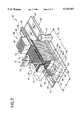
- FIG. 2is a perspective view of a sample transport system having an input queue and a process queue and an output queue;
- FIGS. 3 and 3Aare a top view of a sample transport system
- FIG. 4is a perspective view of a sample transport system
- FIG. 5is a portion of a side view of a sample transport system
- FIGS. 5A and 5Bshow alternative details of FIG. 5;
- FIG. 6is a cross sectional view of a sample rack and a magnet assembly
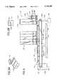
- FIG. 7is a side view of a portion of a sample transport system
- FIG. 8is a bottom view of a drive system
- FIG. 9is an end view of an alternative drive system
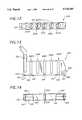
- FIGS. 10 and 11are a series of perspective views of a sample rack
- FIG. 12is a top view of a sample rack
- FIG. 13is a is a side view of a sample rack
- FIG. 14is a bottom view of a sample rack
- FIG. 15is a side view of a sample rack
- FIG. 16is a cross sectional view of a portion of a magnetic sample rack
- FIG. 17is an end view of a sample rack
- FIGS. 18A-18Care a cross sectional view of a sample rack slot showing installation and compression of a spring.
- an automated analyzer instrument 10 used to perform diagnostic tests on test samplesincludes instrumentation generally denoted 12 and a transport system 14.
- the instrumentation 12may typically include an incubation chamber and processing stations similar to the types described in co-pending patent application Ser. No. 08/338,022 filed on Nov. 10, 1994 and assigned to the assignee of the present invention, a luminometer which may be similar to the type described in co-pending patent application Ser. No. 08/035,341 filed on Mar. 19, 1993 and Ser. No. 08/366,003 filed Dec. 29, 1994 both also assigned to the assignee of the present invention and a fluid moving system generally provide from pipettes controlled by robotic arms.
- the transport system 14allows a continuous supply of samples for uninterrupted testing.
- the transportation system 14includes an input queue 16, a process queue 18 and an output queue 20.
- the input queue 16moves sample-containing vessels such as test tubes, for example, toward a load position 22 located at one end of the input queue 16.
- the test tubeshold samples of patient bodily fluid specimens and the like to be analyzed by the analyzer instrument 10. Once the test tubes reach the load position 22, an infeed apparatus 24 moves the sample-containing test tube from the input queue 16 to a predetermined position on the process queue 18.
- the test tubesmove from the input queue 16 to the process queue 18, the test tubes pass by a bar code reader 26 disposed proximate the load position 22 of the input queue 16.
- the bar code reader 26deciphers a bar code typically attached to each test tube and to each rack by a label and transmits its information to a system controller 28 which performs a variety of functions including tracking the samples provided to the process queue 12 and scheduling the order in which the samples are tested.
- the instrumentation apparatus 12aspirates a portion of the sample from the test tube and subsequently dispenses the sample portion into a reaction container such as a cuvette positioned in the instrumentation apparatus 12, where it is treated according to the above identified application '022.
- the sample rackis generally held in the process queue until the test result is obtained. Thus, if a bad test result occurs the test can be rerun by aspirating a second portion of the sample from the test tube and dispensing the second portion into another reaction container.
- the process queue 18positions the sample rack in front of an exit apparatus 30 which moves the sample rack from the process queue 18 to the output queue 20. Once the test tube is moved to the output queue 20, the sample-containing test tubes are again accessible to a user and are typically removed from the transport system 14 periodically.
- the process queue 18is enclosed in protective housing 32 to prevent a user from accessing sample-containing test tubes after the test tubes have been moved from the input queue 16 to the process queue 18.
- the test tubescan be easily accessed and randomly ordered and arranged and re-arranged while on the input queue 16, the placement and ordering of the samples cannot be changed by a user once the samples are moved to the process queue 18 where controller has a record of their position.
- a transport system 14includes an input queue 16, a process queue 18 and an output queue 20.
- a plurality of sample racks generally denoted 33are disposed on the input queue 16 which is provided having a generally rectangular shape.
- Each of the sample racks 33is adapted to hold a plurality of sample-containing test tubes generally denoted 34 and thus the sample racks 33 allow multiple test tubes 34 to be simultaneously moved from the input queue 16 to the process queue 18 and from the process queue 18 to the output queue 20.
- one or more sample racks 33may be placed by a user in any location on the input queue 16. While sample racks 33 are being moved along the input queue 16, the user can remove or arrange the sample racks 33 in a random or a predetermined order.
- the input queue 16is typically an area of the automated analyzer instrument 10 (FIG. 1) which is highly accessible to a user.
- the input queue 16is provided from a tray 38 having a rectangular shape and having a width W corresponding to an exemplary distance typically of about 5.2 inches and an exemplary length L corresponding to a distance typically of about 17.5 inches.
- the width W of the tray 38should be selected to accommodate the length of the sample racks 33 and the length of the tray L should be selected to accommodate a number of sample racks 33.
- the sample racks 33are loaded onto a first surface of the tray 38a such that a handle 39 of each of the sample racks 33 is positioned at a side of the tray 38 proximate the user.
- the handle 39allows a user to easily hold and thus move and arrange sample racks 33 on the tray 38.
- Each of the sample racks 33has a top surface 33a with a plurality of openings therein in which test tubes 34 may be disposed, a front-end, a back-end and a bottom surface having recesses 40 formed therein.
- the tray 38includes a raised central portion 42 extending its length.
- the raised central portion 42serves as a guide along which the sample-rack 33 travels as the sample rack 33 moves from a first end to a second end of the input tray 38 (left to right in the figure).
- the guide 42may be provided as a piece separate from the tray 38, or preferably, the guide 42 may be provided as an integral part of the tray 38 as by plastic injection molding or stamping in aluminum.
- the guide 42should be provided having a height selected to insure that the sample rack 33 does not catch on or become entangled on the guide 42.
- the tray 38further includes a back edge guide 44 which engages a slot 46 in the back-end of the sample rack 33 to prevent the sample rack 33 from becoming dislodged from the tray 38 and to prevent the rack from tipping.
- the tray 38is disposed on a housing 50 which encloses a drive system for the rack 33.
- the drive systemmoves the sample racks 33 along the top surface of the input tray 38 via a magnetic force generated on the underside of the tray 38.
- the tray 38 and housing 50cover the drive system and thus isolate the drive system from the user environment.
- the tray 38 and the housing 50completely enclose the drive system safety hazards due to exposure of a user to moving parts of the drive system are minimized. Furthermore, the tray 38 and cover 50 prevent fluid spills and other undesirable elements (e.g. dust and dirt) from contaminating the drive system or other areas of an analyzer system to which the transport system 14 is coupled and with which the sample transport system 14 cooperates. Also, since the user is not exposed to any moving parts, the drive system need not be shut down prior to or during cleaning of the tray 38 in order to prevent injury to a user or interference by a user with the operation of the drive system.
- undesirable elementse.g. dust and dirt
- the tray 38is relatively easy to clean. Cleaning of the tray 38 is further unimpeded by sample rack positioning structures. This also allows the sample racks 33 to be arbitrarily loaded onto, removed from or rearranged on the tray 38 without interruption of the operation of the transport system 14.
- the process queue 18is disposed adjacent the input queue 16 such that sample racks 33 may be conveniently and easily moved from the end of the input queue 16 to the process queue 18.
- the process queue 18is mounted on a movable carrier member 52.
- a support block 54Disposed on the carrier member 52 is a support block 54 which may be provided, as an aluminum member having a square cross-sectional shape and having a thickness typically of about one inch.
- the support block 54supports a slide 58 a predetermined distance above the carrier member 52, and provides additional structural support to the carrier member 52.
- a drive 53is coupled to move the process queue 18 in response to signals from controller 28.
- a process tray 60mounts on the slide 58 to move on linear bearings mounted on a bottom surface of the process tray 60.
- the process tray 60is provided having a plurality of equally spaced dividing walls 61 projecting from a base surface thereof.
- the dividing walls 61form a plurality of slots 64 in which sample racks 33 may be held.
- An infeed apparatus 51is mounted at a predetermined position on the input queue 16.
- the infeed apparatus 51is mounted at an end of the tray 38.
- the infeed apparatus 51which will be described in detail below in conjunction with FIGS. 3 and 4, moves the sample rack from the load position at the far end of the input queue 16 to an empty slot 64 of the process queue 18.
- the process tray 60is directed by controller 28 to a position to insure that an empty slot 64 is available to receive the sample rack 33 provided by the infeed apparatus 51.
- the process tray 60typically has mounted on one end or the other a probe tip tray 62 in a carrier 68.
- the probe tip tray 62has a plurality of holes 66 in which a plurality of disposable probe tips 70 are arranged.
- the transport system 14further includes an exit pusher 72 having a push rod 74 driven by a motor drive 76.
- the motor drive 76drives the push rod 74 through a slot 64 whereby a sample rack 33 is moved from the process queue 18 onto a surface 78a of an exit tray 78 of the output queue 20 under control of controller 28.
- the exit tray 78includes a guide 80 similar to the guide 42 on the input tray 38. Guides 42, 44 80 and 99 are absent where the sample racks are moved to and from the process queue. Once a sample rack 33 is moved from the process queue 18 to the exit queue 20, an index mechanism 83, which will be described in detail in conjunction with FIG. 3A below, moves the sample rack along the top surface of the exit tray 78.
- the input queue 16is selected having a tray long enough to hold twenty sample racks 33.
- each sample rack 33holds five test tubes 34.
- Each of the test tubes 34have a bar code label attached thereto.
- the test tubes 34are oriented in the sample rack 33 such that the affixed bar code label is exposed to a bar code reader 83 disposed proximate a load position 22 of the input queue 16, where sample racks are moved out of the process queue.
- the infeed mechanism 51is here shown to include a belt 84 endlessly circulating around a pair of pulleys 86a, 86b. As may be more clearly seen in FIG. 4, a first one of the pulleys 86a is coupled to a bidirectional motor 104 such as a stepper motor.
- a plurality of outwardly extending paddles or profiles 88, 88a-88bcoupled to the belt 84 are a plurality of outwardly extending paddles or profiles 88, 88a-88b.
- the profiles 88are placed on a portion only of the belt 84.
- the locations of the end profiles 88a, 88hare selected such that a sample rack 33 can be positioned in the load position 22 between them while the profiles 88b-88h prevent a sample rack 33a adjacent the load position 22 from entering the load position as a rack is moved off between profiles 88a and 88h.
- the belt 84 and profiles 88are urethane and may be manufactured as integral pieces using injection molding techniques.
- the profiles 88may be manufactured as pieces separate from the belt 84.
- the profilescan be attached to the belt 84 via ultrasonic welding or any other fastening techniques well known to those of ordinary skill in the art.
- a load position guide 89Coupled to the input queue 16 proximate the load position 22 is a load position guide 89.
- the load position guide 89prevents tipping of the sample rack in the load position 22.
- the load positionis available to accept a sample rack 33.
- the sample rack 33 which was adjacent the profiles 88is then moved into the space of load position 22 where its presence is sensed by a sensor as described below.
- the motor 104(FIG. 4) then drives the belt 84 and profiles 88 in a clockwise direction. Coupled to profile 88a is an aluminum block 90 which contacts a first end of the sample rack 33 which is now placed in the load position 22 of the input queue 16. As the belt 84 moves in a clockwise direction, the sample rack 33a is pushed from the load position 22 of the input tray 38 to an open slot 64 in the process queue 18 by controller 28.
- Block 90extends the distance which the surface contacting the end of the sample rack 33 travels ensuring that the sample rack 33 is pushed completely off the input queue 16 and completely on to the process queue 18.
- the process queue 18accepts the sample racks 33 fed thereto by the infeed mechanism 51. As described above, the process queue 18 moves linearly along a track such that sample racks 33 from the input queue 16 may be fed into different spaces 64 of the process queue 18. Also the process queue 18 moves along the track to align particular sample racks 33 with the exit pusher 72 under control of controller 28.
- the process queue 18positions sample racks 33 whose samples have been successfully tested in the process queue 18 in front of the exit pusher 72.
- the exit pusher 72includes the push rod 74 driven by a bidirectional motor 76. At position 97, the exact pusher 72 pushes the sample rack out onto the output queue.
- a sensor 98 at an end of the exit queue 20indicates to the controller 28 when the output queue 20 fills with sample racks 33 a signal and either notify a user to take some action such as removing sample racks 33 from the output queue 20 and/or prevent any additional sample racks 33 from being moved from the process queue 18 to the output queue 20 until space is made available on the output queue 20.
- the sensormay be disposed on a top or bottom surface of the tray 78.
- the transport system 14also has an emergency sample rack entry queue 105.
- Entry queue 105includes a stat-entry position 101, a stat sensor 102 and a stat-load position 103.
- the purpose of the stat-entry queue 105is to allow a user to have the analyzer system 10 perform a test out of order as soon as possible on any samples loaded the in stat-entry queue 105.
- stat sensor 102When a user places a sample rack 33 into the stat-entry position 101, the stat sensor 102 activates pusher block 108 (FIG. 3A) which pushes the sample rack from the stat-entry position 101 to the stat-load position 103 with profiles 88 set to the appropriate side of belt 84.
- a stat-load position guide 113is disposed proximate the stat-load position 103 to prevent tipping of the sample rack in the stat-load position 103.
- the infeed apparatus 51then moves the sample rack from the stat-load position 103 to process queue 18 by reverse rotation of the belt 84.
- the transport system 14further includes the bar code reader 83 disposed proximate the stat-entry position 101. Portions of the bar code reader 83 have here been removed to allow a clearer view of the pusher bar 106 and pusher block 108.
- the bar code reader 83is held in a fixed position above the pusher block 108 by a mounting member 109 which may be provided as a mounting bracket for example.
- the bar code reader 83is preferably positioned such that it can read bar codes on labels attached to the test tubes being moved to the process queue 18 from either the load position 22 (FIG. 3) on input queue 16 or from the stat-load position 103.
- the bar code labelsmove past the bar code reader 83 and the bar code reader 83 decodes the information from the bar code label and sends such information to the system controller 28 (FIG. 1).
- This informationmay include, patient, sample, and other direct fluid data. Tests to be run on each sample are entered separately into controller 28. Some samples may be identified for "batch runs" meaning a specified set of tests for all specimens in the batch.
- a magnetic conveyor 110is provided for the input queue 18.
- the drive system 116includes first and second drive belts 117 disposed around a pair of pulleys 118a, 118b, driven by a drive motor 119. Belts 117 are placed near front and back portions of tray 38.
- the drive motor 119is here provided as a stepper motor 119 having a drive gear 123 coupled to pulley 118b which is provided as a pulley gear 118b (FIG. 5B).
- the couplingis accomplished with a 2:1 gear reduction ratio.
- the drive motor 119may be disposed below the transport tray 38 and coupled to pulley 118a via a drive belt 120.
- a plurality of magnet assemblies 121a-121eare coupled to each drive belt 117.
- the magnet assemblies 121a-121eare equally spaced apart by a predetermined distance.
- the tray 38is spaced a predetermined distance above the belt 117 such that the magnet assemblies 121a, 121c and 121e as shown in FIG. 5, pass under the tray 38 a predetermined distance.
- Each magnet assembly 121a-121eincludes a magnet having a magnetic force of sufficient strength such that a magnetic force is present at least at, and in this embodiment preferably above, the surface 114a of the tray 38.
- the sample racks 33include a magnetically attractive region engageable by the magnetic force of magnet assemblies 121.
- the magnet assemblies 121thus magnetically couple the sample racks 33 to the drive system such that drive system moves the sample racks 33 along the surface of the tray 38.
- each magnet assembly 121is of a magnetic strength sufficient to move several sample racks 33.
- the conveyor system 110further includes a sensor 124 coupled to a base plate 126 and disposed below a surface of the belt 117.
- the sensor 124may be provided as a Hall effect sensor, for example, and is disposed to provide a signal whenever a magnet assembly 121 passes thereover. The sensor 124 thus indicates the position of a magnet assembly 121. Since the location of each of the magnet assemblies 121a-121e on the belt 117 with respect to the other is known, when the location of one of the magnet assemblies 121 is known, the location of each of the magnet assemblies 121 is known.
- the transport system 110further includes a load position sensor 128 which may, for example, be provided as an optical sensor which detects light reflected from a surface of a sample rack 33 adjacent it.
- a load position sensor 128which may, for example, be provided as an optical sensor which detects light reflected from a surface of a sample rack 33 adjacent it. In operation, as a sample rack 33 moves into the load position in front of profile 88a, light reflects off a surface 201 (FIG. 10) of the sample rack 33 and activates the load position sensor 128.
- the drive motor 119coupled to pulley 129 turns the belt 117 in a clockwise direction until, typically three magnet assemblies 121 pass by the sensor 128. This step ensures that any sample rack 33 positioned on the left most side of the tray 38 travels the entire length of the tray 114.
- the drive motor 119then turns the belt 117 in a counterclockwise direction by a predetermined short distance (typically 0.06 in.) to relieve any pressure applied to a sample rack in the load position due to an adjacent sample rack.
- a predetermined short distancetypically 0.06 in.
- the drive systemhere provided from the belt 117, pulleys 118 and motor 119 is completely independent of the tray 38 and magnet assemblies 121.
- the drive system 116may be alternatively implemented by any means for moving the magnet assemblies 121 such as electromagnetic means or other means.
- the magnet assembliesmay be provided as having electromagnets which may be turned on and off to attract the magnetically attractive regions of the sample racks.
- electromagnetsmay be moved via a conveyor type belt similar to belt 117 or via pusher rods which move back and forth in a linear direction below the tray. With the pusher rod approach the electromagnets would be activated as the push rods move the magnets and thus sample racks from a position distal to the load position to a position proximate the load position. The electromagnets would then be de-activated prior to the push rods retracting the electromagnets from the load position. Furthermore, with the input tray completely filled, in the case where electromagnets are used on belt 117, it need not be turned off to prevent magnet forces from continuously pushing against the sample racks, rather, the electromagnets may be turned off.
- FIG. 6a portion of the magnetic conveyor 110 described above in conjunction with FIG. 5, is shown having three sample racks 33 disposed thereon. Top portions of each of the sample racks 33 have been removed to reveal test tubes 130 disposed in each of the sample racks. A bottom portion of the sample rack 33, has been cut away to expose in section, a plate 134 disposed in a bottom portion of the sample rack 33.
- the plate 134may be provided from any magnetically attractive material.
- the plate 134is provided from magnetic stainless steel having a thickness typically of about 0.125 inches. In alternate embodiments, however, other materials such as iron, non-stainless steel or even a magnet material may also be used. In the event that plate 134 is provided from a magnet material care should be taken to ensure that a magnetic pole of plate 134 is not in opposition to a magnetic pole of magnet assembly 121.
- the magnet assemblies 121include an aluminum housing 136 having a thickness typically of about 0.090 inches over which shown in section, a backing plate 138, a bar magnet 140 and a magnet cover 142, are disposed.
- the backing plate 138is provided from magnetic stainless steel and is provided having a thickness typically of about 0.060 inches.
- the magnet 140may be provided as a neodymium-iron-boron magnet having a thickness typically of about 0.250 inches and the magnet cover 142 may be provided from a plastic material such as Acetal or any similar material having a thickness typically of about 0.040 inches.
- the magnet assembly 121is coupled to a profile 144 projecting from a surface of the belt 117.
- the profile 144may be similar to the profiles 88 described above in conjunction with FIGS. 3 and 4.
- the magnet assemblies 121can be coupled to the profile 144 via screws which pass through clearance holes provided in the profile 144 and mate with threaded holes provided in the aluminum housing 136 or may be fastened to the profile 144 via epoxy or welding techniques well known to those of ordinary skill in the art.
- the backing plate 138is provided to increase the strength of the magnetic field provided by the magnet 140 by providing a return path coupling assemblies 121 for each belt 117.
- the backing plate 138also modifies the configuration of the magnetic field provided by magnet 140.
- the magnet 140is spaced a distance below the tray surface such that the magnetic field is concentrated in a region at or above the surface of tray 38 upon which the sample racks 33 are disposed.
- a first edge of the plate 134forms a right angle with the tray surface thus generating a relatively strong magnetic couple such that the magnet assemblies 121 can pull the sample racks 33.
- a second, rearward edge of the plate 134is provided having an angled surface as will be described further below.
- the tray 38is, in this embodiment, provided from an aluminum sheet having a thickness typically of about 0.0625 inches.
- the surface of the aluminum sheet on which the sample racks 33 are disposedis provided having a polytetrafluorethylene type of coating, such as Teflon® disposed thereon to reduce frictional forces between the tray 38 surface and the contacting surface of the sample racks 33.
- Teflon®a polytetrafluorethylene type of coating
- FIG. 7a portion of the conveyor system 110 is shown having sample rack 33 disposed in the load position of an input queue.
- the load positioncorresponds to a channel defined on one side by a shoulder 38c of the tray 38.
- a load position guide 150is disposed proximate the load position. In operation, as the sample rack 33 is moved into the load position of the input queue, the load position guide 150 engages a slot 152 formed in the front end of the sample rack 33. The guide 150 ensures that the sample rack 112 is properly aligned in the load position.
- the sensor 128sends a signal which under control of controller 28 activates the infeed apparatus 51 and causes the belt 84 to turn the profile 88a and member 90 (FIG. 3) to drive the sample rack 33 onto the process queue.
- the profile 88ais provided having a height H typically of about one inch, a width W typically of about 0.750 inches and a thickness T typically of about 0.125 inches.
- a bottom edge 89 of profile 88ais spaced a predetermined distance from the top surface of the tray 38, typically of about 0.25 inches.
- the magnet assembly 121is coupled to the profile 144 projecting from the belt 117. As the magnet assembly 121 approaches the end of the tray 38 proximate the profiles 88 and pulley 118a, the magnet assembly 121 is extended past the end of the pulley 118a, insuring that the sample rack 33 is moved completely into the load position of the tray 38. Thus, by coupling the magnet 140 to the profile 144 as described above, the magnet assembly 121 moves the sample rack 33 past the end of the belt 117 as it rounds the pulley 118a.
- the pulleys 118a or 118bhave sets of teeth to engage corresponding recesses in the belt 117 to preserve indexing.
- the pulleys 118turn to move the belt 117 an additional distance to move any other sample racks 33 on the tray 114 toward the load position.
- the belt 117stops moving, with one of magnet assemblies 121 positioned by controller 28 under the sample rack which is next in line to be moved to the load position when the belt 112 executes a short move back away from the load position, the sample rack 33 in the load position remains in the load position while the other sample racks 33 moves away slightly to prevent jamming at the load position.
- the drive assembly 116is shown to include a pair of like stainless steel shafts 162, 164 spaced apart and disposed at opposing ends of tray 114.
- shaft 164each end of the shaft 164 is coupled to a ball bearing assembly 166 mounted as shown in respective ends of mounting plates 167a, 167b generally denoted 167 extending below tray 114.
- the ball bearing assemblies 166allow the shafts 162, 164 to rotate relative to the mounting plates 167.
- Each shaft 162, 164has mounted thereon the paired drive pulleys 118a, 118b. Disposed adjacent one belt pulley 118b is a drive gear 123.
- an alternate drive pulley 176is coupled to a shaft 164, and driven by a drive motor 177 the through shaft 122, pulley 181 and belt 180.
- the drive shaft 162is here provided from a pair of shafts 192, 194 held together by a combination of shoulder regions 196 and a locking collar 198.
- the shafts 162, 164can be easily assembled and disassembled to allow easy access for repair and replacement.
- an input queue back edge guide 44, a load guide 89, and an output queue back edge guide 99are disposed on the tray 114.
- a sample rack 200 corresponding to rack 33has first and second opposing ends 200a, 200b, a top surface 200c, a bottom surface 200d (FIG. 14) and a pair of opposing side surfaces 200e, 200f (FIG. 16).
- An optional reflective member 201is disposed on surface 200e.
- the reflective member, 201reflects light to activate optical sensor 128 (FIG. 5).
- the reflective membercan be disposed along any portion of surface 200e where it may be aligned to activate sensor 128.
- member 201is omitted (FIG. 11) and surface 200e is made of a reflective material or polished such that light incident thereon is reflected and activates sensor 128.
- a plurality of openings 202a-202eare formed in top surface 200c of rack 200 in the typical case there are five openings.
- the openings 202a-202eare provided having a shape selected to accept a sample containing vessel.
- the openings 202are provided having a circular shape selected to accommodate test tubes in a range of sizes.
- Each of the openings 202a-202ehas a corresponding slot 204a-204e formed in the side surface 200e of the sample rack 200.
- the slots 204a-204eextend from the top of the respective openings 200a-200e toward the bottom surface 200d of the sample rack 200.
- a finger spring 206a-206eDisposed in each of the openings 202a-202e is a finger spring 206a-206e.
- openings 202are provided having a length typically of about 1.7 inches and a diameter typically of about 0.675 inches.
- Springs 206are provided having a length typically of about 1.5 inches and a width typically of about 0.313 inches and slots are provided having a width typically of about 0.345 inches.
- the slot walls 205(FIG.
- FIGS. 18A-Care section views down the middle of a slot 204 of a sample rack 33 showing installation and compression in use, holding a test sample container 34, of a spring 206.
- a spring 206At the rear of each slot 204 are top and bottom lipped spring retaining grooves 203 and 205 respectively.
- the groovesare formed by ridges 207 that are formed on each side of the slot 204 creating two grooves 203 and 205.
- the springs 206have rolled ends 208 which aid in retaining the spring in the rack by slipping over the tips of grooves 203 and 205.
- the normal unstressed position of the spring 206is shown in FIG. 18A.
- the bottom end 208fails to reach grooves 205 until this spring is extended during installation so that lower rolled end 208 falls into grooves 205.
- spring 206is stressed further under a force 211 extending the bottom end 208 downward into a slack accommodation extension 213 of groove 205.
- tube removal spring 206returns to the state of FIG. 18B.
- the test tube 214has affixed thereto a bar code label 216. A portion of the test tube 214 to which the bar code label is attached is exposed through the slot 204a and thus visible to the reader 83.
- sample rackscan hold test tubes having a range of diameters, it should also be noted that within this range it is preferable to place test tubes having similar diameters in the same sample rack. Thus, and as will be described further below, while each sample rack can hold test tubes having a diameter in the range of 10.25-16.5 mm it may be desirable to designate particular racks to hold test tubes having diameters within a particular range.
- the openings 202a-202eare provided having a circular cross sectional shape, other cross sectional shapes may also be used.
- the openingmay be provided having a rectangular, square, triangular or any other cross-sectional shape.
- the openingmay be provided having tapered walls to thus more easily hold cone-shaped vessels.
- the particular shape of the openingshould be selected such that the sample-containing vessel disposed therein can be easily placed into and removed from the sample rack 200.
- the openings 202a-202eneed not all have the same shape. Regardless of the size and shape of the openings, the spring arrangement described above can be employed to secure and firmly hold the sample-containing vessels therein.
- the front end of the sample rackhas load slot 152 formed therein.
- the load slot 152accepts the load guide 150, (FIGS. 7 and 9 respectively) to thus properly align the sample rack 200 in the load position of the input queue.
- the back end of the sample rack 200has opening 46 which mates with the input queue edge guide 48 (FIGS. 2, 3) and exit queue edge guide 99 (FIGS. 2, 3).
- the opening 46includes a raised portion 222 which engages a corresponding shape on the input queue guide 48 which assists in locating the sample rack 200 on the input queue and prevents the rack 200 from tipping over or sliding off of the input queue.
- the back edge guide 99is provided as an L-shaped member.
- the guide 99thus mates only with a front portion 46a of the opening 46 such that the racks may be easily removed from the exit queue.
- the sample rack 200also includes a handle 224 with which a user may carry the sample rack 200.
- a top angled portion of the handlehas a depression 226 formed therein to lend an ergonomic design which is comfortable for a user to grasp.
- the handle 224also has a side surface 228 on which may be attached a vertical bar code label 229.
- the vertical bar code label 229has a plurality of barcodes disposed thereon.
- the barcodesidentify the size (e.g. diameter range) of test tubes which are accommodated in the sample rack 200.
- a sliding clip 233is disposed around the handle 224 of the sample rack 200 and a user arranges the clip 233 to indicate the size of test tube actually disposed in the sample rack 200.
- a further barcode region 230identifies the sample rack serial number. Thus each individual sample rack has its own unique identifying number.
- the barcode readerIn operation, when the sample rack 200 is moved from the input queue to the process queue the barcode reader reads the barcode on label 228 which are either not blocked by or are emphasized by the sliding clip 233. Thus the barcode reader can identify the type (i.e. the size) of the test tube disposed in the sample rack 200. As mentioned above the sample rack 200 is able to hold test tubes having different diameters and shapes. However, to improve alignment at the sample probe with the opening of the test tube, the system controller preferably knows the type of the test tube.
- the entire sample rack 200 including handle 224may be provided as a single piece via injection molding techniques.
- the test tube carrying portion of the sample rack 200 and the handle 224may be provided as separate pieces and mated together via screws, epoxy, or any other fastening technique well known to those of ordinary skill in the art.
- a pair of screws in holes 231a, 231bsecure the handle 224 to the base portion of the sample rack 200 via screws 231c, not shown.
- each of the holes 202may optionally be provided with slots 225 formed in the bottom thereof to stabilize the test tube in the holes 202.
- the bottom surface of the sample rack 200has a grove 234 formed therein which mates with and accommodates the guides 42, 80 (FIG. 2) of the input and exit queues.
- the bottom surface of the sample rack 200also has formed therein a pair of rectangular shaped cavities 240 (FIG. 13).
- a magnetically attractive member 244(FIG. 15) is disposed in each of the cavities 240.
- the magnetically attractive membermay be molded into the bottom surface of the sample rack.
- a cover 246may likewise be fastened to the sample rack over member 244.
- the members 244are symmetrically disposed about a latitudinal center line 245 of the sample rack 200.
- each of the magnetically attractive members 244is provided as a magnetically attractive stainless steel plate having a generally rectangular shape. As may be more clearly seen in FIG. 15, a first portion 244c of the bottom surface is slightly recessed from (or substantially aligned with) the bottom surface of the sample rack 200. A second portion 244b of the plate 244 angles into the rack 200 body as discussed above.
- a magnet assembly 121approaches the sample rack from a direction such that the magnet first attracts the angled second portion 244b of the member 244.
- the force of the magnetic field provided from the magnet assembly 120(FIG. 6) is gradually introduced to the member 244.
- a pair of covers 246are disposed over the openings 240.
- the covers 246fit into grooves 247 (FIG. 15) formed proximate the openings 240.
- the covers 246are selected to have a size and shape such that the cover 246 forms a snap fit in the openings 240 to thus secure the plates 244 in the rack 200 while leaving exposed at least a portion of the member 244 (FIG. 14).
- sample rack members 244are spaced apart and positioned in the bottom surface of the sample rack 200 such that when the sample rack 200 is placed on a tray of a conveyor system such as the conveyor system of FIG. 8, the magnet assemblies 173, (FIG. 8) coupled to the belts 170a, 170b (FIG. 8) pass directly under the members 244.
- a pair of raised portions or rails 250, 252Projecting from a bottom surface of the sample rack 200 are a pair of raised portions or rails 250, 252.
- the rails 250, 252space the bottom surface of the sample rack along with member 244 from the queue surface and thus the member 244 from a surface on which the racks are placed.
- the rails 250, 252decrease the surface area of the sample rack 200 which contacts, for example, the surface of the tray 114 (FIGS. 5, 6) on which the rack 200 is placed. Consequently frictional forces between the sample rack 200 and the tray 38 are reduced. This results in a lower magnetic force being required to move sample racks 200 along the tray 38.
- the drive systemcould be provided having a single belt and magnet coupled thereto.
- the belt and magnetwould preferably be disposed along a central longitudinal axis of a transport tray.
- the sample rackwould include a single magnetically attractive region disposed in the center of the sample rack and aligned with the single belt and magnet when the sample rack is placed on the transport tray.
- the platecould be provided having different thicknesses on each end.
- a first end of the platecould be relatively thin and a second end of the plate could be relatively thick.
- a magnet coupled to a drive systemwould first encounter the thin end of the plate. This would result in a relatively weak magnetic coupling. The magnet would then engage the thick end of the plate with a relatively strong force. With this arrangement, the sample rack would smoothly transition from a stationary state to a moving state.
Landscapes
- Physics & Mathematics (AREA)
- Health & Medical Sciences (AREA)
- Life Sciences & Earth Sciences (AREA)
- Chemical & Material Sciences (AREA)
- Analytical Chemistry (AREA)
- Biochemistry (AREA)
- General Health & Medical Sciences (AREA)
- General Physics & Mathematics (AREA)
- Immunology (AREA)
- Pathology (AREA)
- Automatic Analysis And Handling Materials Therefor (AREA)
- Sampling And Sample Adjustment (AREA)
Abstract
Description
Claims (10)
Priority Applications (6)
| Application Number | Priority Date | Filing Date | Title |
|---|---|---|---|
| US08/502,610US5735387A (en) | 1995-07-14 | 1995-07-14 | Specimen rack handling system |
| CA002178296ACA2178296A1 (en) | 1995-07-14 | 1996-06-05 | Specimen rack handling system |
| MX9602285AMX9602285A (en) | 1995-07-14 | 1996-06-11 | Specimen rack handling system. |
| DE69633485TDE69633485T2 (en) | 1995-07-14 | 1996-07-12 | Handling system for sample tube stand |
| EP96305155AEP0753747B1 (en) | 1995-07-14 | 1996-07-12 | Specimen rack handling system |
| JP18499396AJP3880659B2 (en) | 1995-07-14 | 1996-07-15 | Transfer device and analyzer using the same |
Applications Claiming Priority (1)
| Application Number | Priority Date | Filing Date | Title |
|---|---|---|---|
| US08/502,610US5735387A (en) | 1995-07-14 | 1995-07-14 | Specimen rack handling system |
Publications (1)
| Publication Number | Publication Date |
|---|---|
| US5735387Atrue US5735387A (en) | 1998-04-07 |
Family
ID=23998594
Family Applications (1)
| Application Number | Title | Priority Date | Filing Date |
|---|---|---|---|
| US08/502,610Expired - LifetimeUS5735387A (en) | 1995-07-14 | 1995-07-14 | Specimen rack handling system |
Country Status (6)
| Country | Link |
|---|---|
| US (1) | US5735387A (en) |
| EP (1) | EP0753747B1 (en) |
| JP (1) | JP3880659B2 (en) |
| CA (1) | CA2178296A1 (en) |
| DE (1) | DE69633485T2 (en) |
| MX (1) | MX9602285A (en) |
Cited By (117)
| Publication number | Priority date | Publication date | Assignee | Title |
|---|---|---|---|---|
| US5904899A (en)* | 1997-05-15 | 1999-05-18 | Tosoh Corporation | Assaying apparatus and a vessel holder device in use with the assaying apparatus |
| US6068437A (en)* | 1998-11-24 | 2000-05-30 | Lab-Interlink | Automated laboratory specimen organizer and storage unit |
| US6074617A (en)* | 1998-07-10 | 2000-06-13 | Bayer Corporation | Stat shuttle adapter and transport device |
| US6077481A (en)* | 1997-03-31 | 2000-06-20 | Japan Tobacco, Inc. | Automatic pretreatment system for analyzing component of specimen |
| US6141602A (en)* | 1997-09-25 | 2000-10-31 | Hitachi, Ltd. | Specimen processing system |
| US6156575A (en)* | 1997-12-02 | 2000-12-05 | Roche Diagnostic Corporation | Sample processing system and method |
| US6179109B1 (en)* | 1997-03-03 | 2001-01-30 | Gilgen Fordersysteme | Conveyor device for shelf channels in shelf-storage systems |
| US6315108B1 (en)* | 1996-05-06 | 2001-11-13 | Ebm Techniek B.V. | Carrying device for carrying a number of products, as well as a system provided with such carrying device |
| US6331437B1 (en)* | 1998-07-14 | 2001-12-18 | Bayer Corporation | Automatic handler for feeding containers into and out of an analytical instrument |
| US6403035B1 (en)* | 1998-09-28 | 2002-06-11 | Roche Diagnostics Corporation | Apparatus for transporting components within an automatic analyzer system |
| US6435582B1 (en) | 2000-07-31 | 2002-08-20 | Motoman, Inc. | Object manipulator and manipulation system |
| US6495369B1 (en)* | 1998-08-10 | 2002-12-17 | Caliper Technologies Corp. | High throughput microfluidic systems and methods |
| US20030087447A1 (en)* | 2001-11-08 | 2003-05-08 | Blouin Matthew R | Sample well strip |
| US6571934B1 (en) | 2001-11-14 | 2003-06-03 | Dade Behring Inc. | Bi-directional magnetic sample rack conveying system |
| US20030120633A1 (en)* | 2001-11-13 | 2003-06-26 | Torre-Bueno Jose De La | System for tracking biological samples |
| US20030129095A1 (en)* | 2002-01-04 | 2003-07-10 | Farina Edward Francis | Stackable aliquot vessel array |
| USD481133S1 (en) | 2002-04-18 | 2003-10-21 | Instrumentation Laboratory Company | Sample well-strip for an automated sample analyzer |
| US20030228038A1 (en)* | 1995-11-30 | 2003-12-11 | Chroma Vision Medical Systems, Inc., A California Corporation | Method and apparatus for automated image analysis of biological specimens |
| US20030231791A1 (en)* | 2002-06-12 | 2003-12-18 | Torre-Bueno Jose De La | Automated system for combining bright field and fluorescent microscopy |
| USD484989S1 (en) | 2002-09-20 | 2004-01-06 | Dade Behring Inc. | Multi-well liquid container |
| US20040070987A1 (en)* | 2002-10-01 | 2004-04-15 | Kazuhito Iwaki | Vehicular lamp |
| US6790413B2 (en) | 2001-05-03 | 2004-09-14 | Beckman Coulter, Inc. | Sample presentation unit |
| US20040202357A1 (en)* | 2003-04-11 | 2004-10-14 | Perz Cynthia B. | Silhouette image acquisition |
| US6832722B1 (en)* | 1999-09-15 | 2004-12-21 | Diesse Diagnostica Senese S.P.A. | Method and means for data management in a laboratory |
| US20050037406A1 (en)* | 2002-06-12 | 2005-02-17 | De La Torre-Bueno Jose | Methods and apparatus for analysis of a biological specimen |
| US20050047896A1 (en)* | 1995-09-27 | 2005-03-03 | Susumu Takaiti | Method and apparatus for collectively changing components at component supply section |
| US20050071110A1 (en)* | 2003-09-25 | 2005-03-31 | Davis Randall R. | Method for identifying objects to be used in an automatic clinical analyzer |
| US20050281484A1 (en)* | 2004-06-17 | 2005-12-22 | Perz Cynthia B | System and method of registering field of view |
| US20060002636A1 (en)* | 2004-06-30 | 2006-01-05 | Torre-Bueno Jose D L | Data structure of an image storage and retrieval system |
| US20060147298A1 (en)* | 2005-01-05 | 2006-07-06 | Samsung Sdi Co., Ltd. | Apparatus for transferring a tray |
| US20060263248A1 (en)* | 2005-05-04 | 2006-11-23 | Gomm Cordell K | Reagent and sample handling device for automatic testing system |
| US20070031043A1 (en)* | 2005-08-02 | 2007-02-08 | Perz Cynthia B | System for and method of intelligently directed segmentation analysis for automated microscope systems |
| US7190818B2 (en) | 1996-11-27 | 2007-03-13 | Clarient, Inc. | Method and apparatus for automated image analysis of biological specimens |
| US20070110617A1 (en)* | 2005-11-15 | 2007-05-17 | Sysmex Corporation | Sample analyzer and sample container supplying apparatus |
| US20070207056A1 (en)* | 2004-03-05 | 2007-09-06 | Veiner Craig R | Specimen-transport module |
| US20080272283A1 (en)* | 2001-12-06 | 2008-11-06 | Feldsine Philip T | Sample collection and testing system |
| US20090028759A1 (en)* | 2007-07-26 | 2009-01-29 | Industrial Technology Research Institute | Magnetic separation device |
| CN100564577C (en)* | 2005-01-05 | 2009-12-02 | 三星移动显示器株式会社 | The device that is used for delivery tray |
| US20090326324A1 (en)* | 2006-07-28 | 2009-12-31 | Universidad De Malaga | Robotic system for assisting in minimally-invasive surgery, which can position a surgical instrument in response to orders from a surgeon, is not attached to the operating table and does not require pre-calibration of the insertion point |
| US20100276256A1 (en)* | 2009-03-03 | 2010-11-04 | Ats Automation Tooling Systems Inc. | Multi-mode and multi-pitch conveyor system |
| US20110008796A1 (en)* | 2008-03-11 | 2011-01-13 | Imagene, S.A. A Directoire | Industrial method for the encapsulation of biological material for the purpose of storage at ambient temperature with a vacuum seal test of the encapsulation |
| US20110048104A1 (en)* | 2008-03-14 | 2011-03-03 | Cheyney Design & Development Limited | Test apparatus |
| EP2299280A2 (en) | 2009-09-17 | 2011-03-23 | Sysmex Corporation | Sample processing apparatus and sample rack transporting method |
| US20110076780A1 (en)* | 2009-09-29 | 2011-03-31 | Sysmex Corporation | Sample processing apparatus, sample rack transporting method, and apparatus |
| US20110124029A1 (en)* | 2009-05-15 | 2011-05-26 | Biomerieux, Inc. | Automated loading mechanism for microbial detection apparatus |
| US8480954B2 (en) | 2007-02-08 | 2013-07-09 | Biokit, S.A. | Apparatus and methods for dispensing sample holders |
| WO2013177087A3 (en)* | 2012-05-22 | 2014-01-23 | Siemens Healthcare Diagnostics Inc. | Linear random access queue |
| US8645167B2 (en) | 2008-02-29 | 2014-02-04 | Dakocytomation Denmark A/S | Systems and methods for tracking and providing workflow information |
| US20140141465A1 (en)* | 2011-09-29 | 2014-05-22 | Roche Diagnostics Operations, Inc. | Handling of sample tubes comprising geometric tube data |
| US8794426B2 (en) | 2011-03-31 | 2014-08-05 | Ats Automation Tooling Systems Inc. | Pallet-based position adjustment system and method |
| US20140234978A1 (en)* | 2011-11-04 | 2014-08-21 | Roche Diagnostics Operations, Inc. | Laboratory sample distribution system, laboratory system and method of operating |
| US20160077120A1 (en)* | 2014-09-12 | 2016-03-17 | Roche Diagnostics Operations, Inc. | Laboratory sample distribution system and laboratory automation system |
| US9381524B2 (en) | 2011-11-08 | 2016-07-05 | Becton, Dickinson And Company | System and method for automated sample preparation |
| US9423410B2 (en) | 2014-02-17 | 2016-08-23 | Roche Diagnostics Operations, Inc. | Transport device, sample distribution system, and laboratory automation system |
| US9423411B2 (en) | 2014-02-17 | 2016-08-23 | Roche Diagnostics Operations, Inc. | Transport device, sample distribution system and laboratory automation system |
| US9446406B2 (en) | 2012-06-29 | 2016-09-20 | Biocontrol Systems, Inc. | Sample collection and bioluminescent analysis system |
| USRE46214E1 (en)* | 2001-03-16 | 2016-11-22 | Beckman Coulter, Inc. | Method and system for sample aliquot storage |
| US9567167B2 (en) | 2014-06-17 | 2017-02-14 | Roche Diagnostics Operations, Inc. | Laboratory sample distribution system and laboratory automation system |
| US9574219B2 (en) | 2009-05-15 | 2017-02-21 | Biomerieux, Inc. | Device for sampling a specimen container |
| US9593970B2 (en) | 2014-09-09 | 2017-03-14 | Roche Diagnostics Operations, Inc. | Laboratory sample distribution system and method for calibrating magnetic sensors |
| US9598243B2 (en) | 2011-11-04 | 2017-03-21 | Roche Diagnostics Operations, Inc. | Laboratory sample distribution system and corresponding method of operation |
| US9618525B2 (en) | 2014-10-07 | 2017-04-11 | Roche Diagnostics Operations, Inc. | Module for a laboratory sample distribution system, laboratory sample distribution system and laboratory automation system |
| US9658241B2 (en) | 2014-03-31 | 2017-05-23 | Roche Diagnostics Operations, Inc. | Sample distribution system and laboratory automation system |
| US9664703B2 (en) | 2011-11-04 | 2017-05-30 | Roche Diagnostics Operations, Inc. | Laboratory sample distribution system and corresponding method of operation |
| US9772342B2 (en) | 2014-03-31 | 2017-09-26 | Roche Diagnostics Operations, Inc. | Dispatching device, sample distribution system and laboratory automation system |
| US9791468B2 (en) | 2014-03-31 | 2017-10-17 | Roche Diagnostics Operations, Inc. | Transport device, sample distribution system and laboratory automation system |
| US9810706B2 (en) | 2014-03-31 | 2017-11-07 | Roche Diagnostics Operations, Inc. | Vertical conveying device, laboratory sample distribution system and laboratory automation system |
| CN107533074A (en)* | 2015-06-22 | 2018-01-02 | 深圳迈瑞生物医疗电子股份有限公司 | A sample analysis device |
| US20180045747A1 (en)* | 2015-02-18 | 2018-02-15 | Siemens Healthcare Diagnostics Inc. | Image-based tray alignment and tube slot localization in a vision system |
| US9902572B2 (en) | 2015-10-06 | 2018-02-27 | Roche Diagnostics Operations, Inc. | Method of configuring a laboratory automation system, laboratory sample distribution system and laboratory automation system |
| US9939455B2 (en) | 2014-11-03 | 2018-04-10 | Roche Diagnostics Operations, Inc. | Laboratory sample distribution system and laboratory automation system |
| US9969570B2 (en) | 2010-05-07 | 2018-05-15 | Roche Diagnostics Operations, Inc. | System for transporting containers between different stations and a container carrier |
| US9989547B2 (en) | 2014-07-24 | 2018-06-05 | Roche Diagnostics Operations, Inc. | Laboratory sample distribution system and laboratory automation system |
| US10006927B2 (en) | 2015-05-22 | 2018-06-26 | Roche Diagnostics Operations, Inc. | Method of operating a laboratory automation system and a laboratory automation system |
| US10012666B2 (en) | 2014-03-31 | 2018-07-03 | Roche Diagnostics Operations, Inc. | Sample distribution system and laboratory automation system |
| US10094843B2 (en) | 2015-03-23 | 2018-10-09 | Roche Diagnostics Operations, Inc. | Laboratory sample distribution system and laboratory automation system |
| US10119982B2 (en) | 2015-03-16 | 2018-11-06 | Roche Diagnostics Operations, Inc. | Transport carrier, laboratory cargo distribution system, and laboratory automation system |
| US10160609B2 (en) | 2015-10-13 | 2018-12-25 | Roche Diagnostics Operations, Inc. | Laboratory sample distribution system and laboratory automation system |
| US10175259B2 (en) | 2015-09-01 | 2019-01-08 | Roche Diagnostics Operations, Inc. | Laboratory cargo distribution system, laboratory automation system and method of operating a laboratory cargo distribution system |
| US10197586B2 (en) | 2015-10-06 | 2019-02-05 | Roche Diagnostics Operations, Inc. | Method of determining a handover position and laboratory automation system |
| US10197555B2 (en) | 2016-06-21 | 2019-02-05 | Roche Diagnostics Operations, Inc. | Method of setting a handover position and laboratory automation system |
| US10228384B2 (en) | 2015-10-14 | 2019-03-12 | Roche Diagnostics Operations, Inc. | Method of rotating a sample container carrier, laboratory sample distribution system and laboratory automation system |
| US10239708B2 (en) | 2014-09-09 | 2019-03-26 | Roche Diagnostics Operations, Inc. | Laboratory sample distribution system and laboratory automation system |
| US10288633B2 (en) | 2015-06-26 | 2019-05-14 | Abbott Laboratories | Reaction vessel moving member for moving reaction vessels from a processing track to a rotating device in a diagnostic analyzer |
| US10352953B2 (en) | 2015-05-22 | 2019-07-16 | Roche Diagnostics Operations, Inc. | Method of operating a laboratory sample distribution system, laboratory sample distribution system and a laboratory automation system |
| US10379130B2 (en) | 2015-06-26 | 2019-08-13 | Abbott Laboratories | Reaction vessel exchanger device for a diagnostic analyzer |
| US10416183B2 (en) | 2016-12-01 | 2019-09-17 | Roche Diagnostics Operations, Inc. | Laboratory sample distribution system and laboratory automation system |
| US10436808B2 (en) | 2016-12-29 | 2019-10-08 | Roche Diagnostics Operations, Inc. | Laboratory sample distribution system and laboratory automation system |
| US10451567B2 (en)* | 2017-11-17 | 2019-10-22 | Mettler-Toledo, LLC | Radiographic product inspection system with reject bin |
| US10495657B2 (en) | 2017-01-31 | 2019-12-03 | Roche Diagnostics Operations, Inc. | Laboratory sample distribution system and laboratory automation system |
| US10509049B2 (en) | 2014-09-15 | 2019-12-17 | Roche Diagnostics Operations, Inc. | Method of operating a laboratory sample distribution system, laboratory sample distribution system and laboratory automation system |
| US10520520B2 (en) | 2016-02-26 | 2019-12-31 | Roche Diagnostics Operations, Inc. | Transport device with base plate modules |
| CN110683327A (en)* | 2018-07-04 | 2020-01-14 | 深圳迈瑞生物医疗电子股份有限公司 | Sample rack scheduling mechanism and method |
| US10564170B2 (en) | 2015-07-22 | 2020-02-18 | Roche Diagnostics Operations, Inc. | Sample container carrier, laboratory sample distribution system and laboratory automation system |
| US10578632B2 (en) | 2016-02-26 | 2020-03-03 | Roche Diagnostics Operations, Inc. | Transport device unit for a laboratory sample distribution system |
| US10605819B2 (en) | 2016-02-26 | 2020-03-31 | Roche Diagnostics Operations, Inc. | Transport device having a tiled driving surface |
| US10962557B2 (en) | 2017-07-13 | 2021-03-30 | Roche Diagnostics Operations, Inc. | Method of operating a laboratory sample distribution system, laboratory sample distribution system and laboratory automation system |
| US10989726B2 (en) | 2016-06-09 | 2021-04-27 | Roche Diagnostics Operations, Inc. | Laboratory sample distribution system and method of operating a laboratory sample distribution system |
| US10989725B2 (en) | 2017-06-02 | 2021-04-27 | Roche Diagnostics Operations, Inc. | Method of operating a laboratory sample distribution system, laboratory sample distribution system, and laboratory automation system |
| US10996233B2 (en) | 2016-06-03 | 2021-05-04 | Roche Diagnostics Operations, Inc. | Laboratory sample distribution system and laboratory automation system |
| US11092613B2 (en) | 2015-05-22 | 2021-08-17 | Roche Diagnostics Operations, Inc. | Method of operating a laboratory sample distribution system, laboratory sample distribution system and laboratory automation system |
| US11112421B2 (en) | 2016-08-04 | 2021-09-07 | Roche Diagnostics Operations, Inc. | Laboratory sample distribution system and laboratory automation system |
| US11110464B2 (en) | 2017-09-13 | 2021-09-07 | Roche Diagnostics Operations, Inc. | Sample container carrier, laboratory sample distribution system and laboratory automation system |
| US11110463B2 (en) | 2017-09-13 | 2021-09-07 | Roche Diagnostics Operations, Inc. | Sample container carrier, laboratory sample distribution system and laboratory automation system |
| US11150257B2 (en)* | 2017-09-29 | 2021-10-19 | Shenzhen New Industries Biomedical Engineering Co., Ltd. | Sample rack loading system and loading method, and chemiluminescence detector |
| CN113753487A (en)* | 2021-09-07 | 2021-12-07 | 中科计算技术西部研究院 | Automatic pipe connection placing control system and control method |
| US11204361B2 (en) | 2017-02-03 | 2021-12-21 | Roche Diagnostics Operations, Inc. | Laboratory automation system |
| US11226348B2 (en) | 2015-07-02 | 2022-01-18 | Roche Diagnostics Operations, Inc. | Storage module, method of operating a laboratory automation system and laboratory automation system |
| US11709171B2 (en) | 2018-03-16 | 2023-07-25 | Roche Diagnostics Operations, Inc. | Laboratory system, laboratory sample distribution system and laboratory automation system |
| US11747356B2 (en) | 2020-12-21 | 2023-09-05 | Roche Diagnostics Operations, Inc. | Support element for a modular transport plane, modular transport plane, and laboratory distribution system |
| WO2023211860A1 (en)* | 2022-04-25 | 2023-11-02 | Telesis Bio Inc. | Apparatus for delivery of laboratory consumables |
| CN117228303A (en)* | 2023-11-10 | 2023-12-15 | 赣州富尔特电子股份有限公司 | Arrangement conveying device for processing neodymium iron boron cylindrical section bar |
| US11971420B2 (en) | 2018-03-07 | 2024-04-30 | Roche Diagnostics Operations, Inc. | Method of operating a laboratory sample distribution system, laboratory sample distribution system and laboratory automation system |
| US12000850B2 (en) | 2020-06-19 | 2024-06-04 | Roche Diagnostics Operations, Inc. | Laboratory sample distribution system and corresponding method of operation |
| US12000851B2 (en) | 2020-07-15 | 2024-06-04 | Roche Diagnostics Operations, Inc. | Laboratory sample distribution system and method for operating the same |
| GB2615613B (en)* | 2022-02-04 | 2025-05-14 | Automata Tech Limited | Workbench system |
| US12429491B2 (en) | 2020-11-23 | 2025-09-30 | Roche Diagnostics Operations, Inc. | Laboratory sample distribution system and laboratory automation system |
Families Citing this family (21)
| Publication number | Priority date | Publication date | Assignee | Title |
|---|---|---|---|---|
| US6123205A (en)* | 1997-11-26 | 2000-09-26 | Bayer Corporation | Sample tube rack |
| JP2001272408A (en)* | 2000-03-24 | 2001-10-05 | Olympus Optical Co Ltd | Fall prevention mechanism of sample rack |
| EP1270078B1 (en) | 2001-06-22 | 2004-09-15 | Jouan Italia S.R.L. | Apparatus and method for automatic loading and unloading of centrifuge buckets |
| JP4666845B2 (en)* | 2001-09-10 | 2011-04-06 | シスメックス株式会社 | Sample transport device |
| JP3740428B2 (en)* | 2002-03-29 | 2006-02-01 | アロカ株式会社 | Sample pretreatment system |
| US7867444B2 (en)* | 2002-05-30 | 2011-01-11 | Siemens Healthcare Diagnostics, Inc. | Lab cell centrifuging module |
| WO2005093434A1 (en)* | 2004-03-05 | 2005-10-06 | Beckman Coulter, Inc. | Magnetic specimen-transport system for automated clinical instrument |
| US7051495B2 (en) | 2004-06-29 | 2006-05-30 | Lifescan Scotland Limited | Method of packaging integrated biosensors |
| IL169171A0 (en)* | 2004-06-29 | 2007-07-04 | Lifescan Scotland Ltd | Manufacturing apparatus for the packaging of medical devices including integrated lancets |
| SE530192C2 (en)* | 2006-07-19 | 2008-03-25 | Hemocue Ab | Apparatus for imaging samples where the sample holder is removable by magnetic interaction |
| JP4980671B2 (en)* | 2006-08-18 | 2012-07-18 | シスメックス株式会社 | Blood sample analyzer |
| JP2010091469A (en)* | 2008-10-09 | 2010-04-22 | Olympus Corp | Specimen dispensing device, method of dispensing specimen, and analyzer |
| JP2013518251A (en)* | 2010-01-21 | 2013-05-20 | シーメンス・ヘルスケア・ダイアグノスティックス・インコーポレーテッド | Magnetic conveyor system, apparatus and method including moving magnets |
| DE102011075037A1 (en)* | 2011-04-29 | 2012-10-31 | Hamilton Bonaduz Ag | Punching device with mounting plate |
| DE102011075036A1 (en)* | 2011-04-29 | 2012-10-31 | Hamilton Bonaduz Ag | Punching device with gripping unit |
| DE102011075039A1 (en) | 2011-04-29 | 2012-10-31 | Hamilton Bonaduz Ag | Punching device with illuminated mounting plate |
| HUP1100493A2 (en) | 2011-09-08 | 2013-04-29 | Diagon Kft | Method and device for conveying sample stands |
| CN106706941B (en)* | 2016-12-16 | 2018-07-06 | 宁波美康盛德生物科技有限公司 | Multiple sample introduction propulsive mechanism |
| CN109436651B (en)* | 2018-12-03 | 2020-06-05 | 深圳市联新移动医疗科技有限公司 | Western medicine delivery device and system |
| EP4001178A1 (en)* | 2020-11-17 | 2022-05-25 | Uhlmann Pac-Systeme GmbH & Co. KG | Conveyor device and method for conveying piece goods |
| KR102635366B1 (en)* | 2023-05-23 | 2024-02-08 | 주식회사 제놀루션 | Sample processing device and sample processing method |
Citations (42)
| Publication number | Priority date | Publication date | Assignee | Title |
|---|---|---|---|---|
| US2609915A (en)* | 1949-03-10 | 1952-09-09 | Burgh Albert R De | Conveying apparatus |
| US2824638A (en)* | 1954-06-25 | 1958-02-25 | Burgh Raymond J De | Magnetic conveyor |
| US4088254A (en)* | 1976-12-08 | 1978-05-09 | Hooper Joel Ray | Magnetic holding apparatus and methods of constructing and utilizing same |
| US4228831A (en)* | 1978-12-11 | 1980-10-21 | Abbott Laboratories | Probe and syringe drive apparatus |
| US4413534A (en)* | 1980-08-12 | 1983-11-08 | Bodenseewerk Perkin-Elmer & Co., Gmbh | Sample transport mechanism |
| US4438068A (en)* | 1979-11-13 | 1984-03-20 | Technicon Instruments Corporation | Test-tube assembly for immunoassays utilizing magnetically attractable particles |
| US4439700A (en)* | 1981-03-21 | 1984-03-27 | Vacuumschmelze Gmbh | Magnetic drive system for generating linear movements |
| US4526754A (en)* | 1982-07-30 | 1985-07-02 | Technicon Instruments Corporation | Sample transport system |
| US4528159A (en)* | 1981-07-20 | 1985-07-09 | American Hospital Supply Corp. | Automated analysis instrument system |
| US4609017A (en)* | 1983-10-13 | 1986-09-02 | Coulter Electronics, Inc. | Method and apparatus for transporting carriers of sealed sample tubes and mixing the samples |
| US4678752A (en)* | 1985-11-18 | 1987-07-07 | Becton, Dickinson And Company | Automatic random access analyzer |
| US4736748A (en)* | 1986-04-05 | 1988-04-12 | Kuraray Co., Ltd. | Blood component monitoring system |
| US4751184A (en)* | 1986-07-07 | 1988-06-14 | Tosoh Corporation | Selective test pack feeder for biochemical analyzing apparatus |
| US4751186A (en)* | 1984-02-15 | 1988-06-14 | Eppendorf Geratebau Netheler & Hinz Gmbh | Process for performing sample analyses and rack for performing the process |
| US4861553A (en)* | 1987-06-11 | 1989-08-29 | Technicon Instruments Corporation | Automatic sampling system |
| US4861554A (en)* | 1981-12-14 | 1989-08-29 | Olympus Optical Co., Ltd. | Automatic analyzing apparatus for analyzing agglutination patterns |
| US4896064A (en)* | 1981-02-06 | 1990-01-23 | Nova Scotia Research Foundation Corp. | Low loss magnetic drive system |
| US4900513A (en)* | 1986-07-11 | 1990-02-13 | Beckman Instruments, Inc. | Sample loading apparatus |
| US4943416A (en)* | 1987-09-23 | 1990-07-24 | Kabushiki Kaisha Marukomu | Automatic urinalysis system |
| US4944924A (en)* | 1987-06-11 | 1990-07-31 | Technicon Instruments Corporation | Test tube holder |
| US4953684A (en)* | 1987-07-17 | 1990-09-04 | The West Company, Incorporated | Stopper elevator conveyor |
| US4956148A (en)* | 1987-04-22 | 1990-09-11 | Abbott Laboratories | Locking rack and disposable sample cartridge |
| US4964839A (en)* | 1987-10-26 | 1990-10-23 | Rosy B. Versand Gmbh | Drive shaft with a coupling arrangement |
| US4981208A (en)* | 1990-02-16 | 1991-01-01 | The Cambridge Wire Cloth Company | Magnetic drive spiral conveyor system |
| US4994240A (en)* | 1986-06-10 | 1991-02-19 | Tosoh Corporation | Suction head and carrying reaction cups used in biochemical reaction analyzing apparatus |
| US5008082A (en)* | 1988-08-25 | 1991-04-16 | Eastman Kodak Company | Analyzers using linear sample trays with random access |
| US5012669A (en)* | 1988-10-03 | 1991-05-07 | Panametrics, Inc. | Oxygen sensing method and apparatus |
| US5035861A (en)* | 1987-04-22 | 1991-07-30 | Abbott Laboratories | Locking rack and disposable sample cartridge |
| US5055262A (en)* | 1988-02-22 | 1991-10-08 | Olympus Optical Co., Ltd. | Automatic cuvette loading apparatus |
| US5059393A (en)* | 1989-01-05 | 1991-10-22 | Eastman Kodak Company | Analysis slide positioning apparatus and method for a chemical analyzer |
| US5089424A (en)* | 1988-06-14 | 1992-02-18 | Abbott Laboratories | Method and apparatus for heterogeneous chemiluminescence assay |
| US5104808A (en)* | 1988-08-26 | 1992-04-14 | Laska Paul F | Method and apparatus for effecting a plurality of assays on a plurality of samples in an automatic analytical device |
| US5128105A (en)* | 1988-10-24 | 1992-07-07 | Fritz Berthold | Rack system for a plurality of specimen containers for performing assays |
| US5178834A (en)* | 1989-07-19 | 1993-01-12 | Tosoh Corporation | Automatic immunoassay analyzer |
| US5244633A (en)* | 1992-05-22 | 1993-09-14 | Eastman Kodak Company | Analyzer incubator with plural independently driven rings supporting cuvettes |
| JPH05264413A (en)* | 1992-03-17 | 1993-10-12 | Fujikura Ltd | Method and apparatus for forming meniscus liquid surface |
| EP0565166A2 (en)* | 1992-03-30 | 1993-10-13 | Johnson & Johnson Clinical Diagnostics, Inc. | Sample tube tray and magnetic conveyor |
| US5286651A (en)* | 1989-08-24 | 1994-02-15 | Amoco Corporation | Determining collective fluid inclusion volatiles compositions for inclusion composition mapping of earth's subsurface |
| US5311426A (en)* | 1988-08-02 | 1994-05-10 | Abbott Laboratories | Apparatus and method for providing assay calibration data |
| US5320808A (en)* | 1988-08-02 | 1994-06-14 | Abbott Laboratories | Reaction cartridge and carousel for biological sample analyzer |
| US5324481A (en)* | 1991-06-03 | 1994-06-28 | Abbott Laboratories | Carousel for assay specimen carrier |
| US5366697A (en)* | 1992-03-30 | 1994-11-22 | Eastman Kodak Company | Tray and magnetic conveyor |
Family Cites Families (18)
| Publication number | Priority date | Publication date | Assignee | Title |
|---|---|---|---|---|
| JPS536428B1 (en)* | 1969-02-19 | 1978-03-08 | ||
| JPS5112908B1 (en)* | 1970-07-27 | 1976-04-23 | ||
| GB1393268A (en)* | 1972-12-19 | 1975-05-07 | Philips Electronic Associated | Magnetic conveyor |
| US3854602A (en)* | 1973-08-27 | 1974-12-17 | Coulter Electronics | Magnetic hopper system |
| US3985507A (en)* | 1975-09-05 | 1976-10-12 | International Business Machines Corporation | Automatic test sample handling system |
| JPS58102162A (en)* | 1981-12-15 | 1983-06-17 | Olympus Optical Co Ltd | Method of feeding rack to automatic analyzer |
| JPS58154204U (en)* | 1982-04-07 | 1983-10-15 | 株式会社東京クリニカルラボラトリ− | Sample bottle automatic transfer device |
| JPH0761814B2 (en)* | 1984-09-10 | 1995-07-05 | 三菱化学株式会社 | Carrier |
| JPS61217343A (en)* | 1985-03-18 | 1986-09-26 | 二和印刷株式会社 | Packaging paperboard carton and manufacture thereof |
| JPS63141457U (en)* | 1987-03-06 | 1988-09-19 | ||
| JPH0548130Y2 (en)* | 1987-03-06 | 1993-12-20 | ||
| JPS63286769A (en)* | 1987-05-20 | 1988-11-24 | Kyoto Daiichi Kagaku:Kk | Continuous automatic analyzer using rack and rack transfer device |
| JP2707088B2 (en)* | 1987-11-20 | 1998-01-28 | 株式会社ニッテク | Container transfer method and apparatus |
| JPH0625449Y2 (en)* | 1989-06-30 | 1994-07-06 | 照明 伊藤 | Belt conveyor type test tube carrier |
| JP2867174B2 (en)* | 1990-09-25 | 1999-03-08 | 東亜医用電子株式会社 | Sampler for multiple samples |
| JPH0736284Y2 (en)* | 1990-10-05 | 1995-08-16 | 東亜医用電子株式会社 | Sample identification code reader for sample container |
| JPH0592732U (en)* | 1992-04-24 | 1993-12-17 | 株式会社ニッテク | Rack structure |
| JPH0634642A (en)* | 1992-07-20 | 1994-02-10 | Nittec Co Ltd | Vessel transfer equipment |
- 1995
- 1995-07-14USUS08/502,610patent/US5735387A/ennot_activeExpired - Lifetime
- 1996
- 1996-06-05CACA002178296Apatent/CA2178296A1/ennot_activeAbandoned
- 1996-06-11MXMX9602285Apatent/MX9602285A/enunknown
- 1996-07-12EPEP96305155Apatent/EP0753747B1/ennot_activeExpired - Lifetime
- 1996-07-12DEDE69633485Tpatent/DE69633485T2/ennot_activeExpired - Lifetime
- 1996-07-15JPJP18499396Apatent/JP3880659B2/ennot_activeExpired - Fee Related
Patent Citations (42)
| Publication number | Priority date | Publication date | Assignee | Title |
|---|---|---|---|---|
| US2609915A (en)* | 1949-03-10 | 1952-09-09 | Burgh Albert R De | Conveying apparatus |
| US2824638A (en)* | 1954-06-25 | 1958-02-25 | Burgh Raymond J De | Magnetic conveyor |
| US4088254A (en)* | 1976-12-08 | 1978-05-09 | Hooper Joel Ray | Magnetic holding apparatus and methods of constructing and utilizing same |
| US4228831A (en)* | 1978-12-11 | 1980-10-21 | Abbott Laboratories | Probe and syringe drive apparatus |
| US4438068A (en)* | 1979-11-13 | 1984-03-20 | Technicon Instruments Corporation | Test-tube assembly for immunoassays utilizing magnetically attractable particles |
| US4413534A (en)* | 1980-08-12 | 1983-11-08 | Bodenseewerk Perkin-Elmer & Co., Gmbh | Sample transport mechanism |
| US4896064A (en)* | 1981-02-06 | 1990-01-23 | Nova Scotia Research Foundation Corp. | Low loss magnetic drive system |
| US4439700A (en)* | 1981-03-21 | 1984-03-27 | Vacuumschmelze Gmbh | Magnetic drive system for generating linear movements |
| US4528159A (en)* | 1981-07-20 | 1985-07-09 | American Hospital Supply Corp. | Automated analysis instrument system |
| US4861554A (en)* | 1981-12-14 | 1989-08-29 | Olympus Optical Co., Ltd. | Automatic analyzing apparatus for analyzing agglutination patterns |
| US4526754A (en)* | 1982-07-30 | 1985-07-02 | Technicon Instruments Corporation | Sample transport system |
| US4609017A (en)* | 1983-10-13 | 1986-09-02 | Coulter Electronics, Inc. | Method and apparatus for transporting carriers of sealed sample tubes and mixing the samples |
| US4751186A (en)* | 1984-02-15 | 1988-06-14 | Eppendorf Geratebau Netheler & Hinz Gmbh | Process for performing sample analyses and rack for performing the process |
| US4678752A (en)* | 1985-11-18 | 1987-07-07 | Becton, Dickinson And Company | Automatic random access analyzer |
| US4736748A (en)* | 1986-04-05 | 1988-04-12 | Kuraray Co., Ltd. | Blood component monitoring system |
| US4994240A (en)* | 1986-06-10 | 1991-02-19 | Tosoh Corporation | Suction head and carrying reaction cups used in biochemical reaction analyzing apparatus |
| US4751184A (en)* | 1986-07-07 | 1988-06-14 | Tosoh Corporation | Selective test pack feeder for biochemical analyzing apparatus |
| US4900513A (en)* | 1986-07-11 | 1990-02-13 | Beckman Instruments, Inc. | Sample loading apparatus |
| US5035861A (en)* | 1987-04-22 | 1991-07-30 | Abbott Laboratories | Locking rack and disposable sample cartridge |
| US4956148A (en)* | 1987-04-22 | 1990-09-11 | Abbott Laboratories | Locking rack and disposable sample cartridge |
| US4861553A (en)* | 1987-06-11 | 1989-08-29 | Technicon Instruments Corporation | Automatic sampling system |
| US4944924A (en)* | 1987-06-11 | 1990-07-31 | Technicon Instruments Corporation | Test tube holder |
| US4953684A (en)* | 1987-07-17 | 1990-09-04 | The West Company, Incorporated | Stopper elevator conveyor |
| US4943416A (en)* | 1987-09-23 | 1990-07-24 | Kabushiki Kaisha Marukomu | Automatic urinalysis system |
| US4964839A (en)* | 1987-10-26 | 1990-10-23 | Rosy B. Versand Gmbh | Drive shaft with a coupling arrangement |
| US5055262A (en)* | 1988-02-22 | 1991-10-08 | Olympus Optical Co., Ltd. | Automatic cuvette loading apparatus |
| US5089424A (en)* | 1988-06-14 | 1992-02-18 | Abbott Laboratories | Method and apparatus for heterogeneous chemiluminescence assay |
| US5320808A (en)* | 1988-08-02 | 1994-06-14 | Abbott Laboratories | Reaction cartridge and carousel for biological sample analyzer |
| US5311426A (en)* | 1988-08-02 | 1994-05-10 | Abbott Laboratories | Apparatus and method for providing assay calibration data |
| US5008082A (en)* | 1988-08-25 | 1991-04-16 | Eastman Kodak Company | Analyzers using linear sample trays with random access |
| US5104808A (en)* | 1988-08-26 | 1992-04-14 | Laska Paul F | Method and apparatus for effecting a plurality of assays on a plurality of samples in an automatic analytical device |
| US5012669A (en)* | 1988-10-03 | 1991-05-07 | Panametrics, Inc. | Oxygen sensing method and apparatus |
| US5128105A (en)* | 1988-10-24 | 1992-07-07 | Fritz Berthold | Rack system for a plurality of specimen containers for performing assays |
| US5059393A (en)* | 1989-01-05 | 1991-10-22 | Eastman Kodak Company | Analysis slide positioning apparatus and method for a chemical analyzer |
| US5178834A (en)* | 1989-07-19 | 1993-01-12 | Tosoh Corporation | Automatic immunoassay analyzer |
| US5286651A (en)* | 1989-08-24 | 1994-02-15 | Amoco Corporation | Determining collective fluid inclusion volatiles compositions for inclusion composition mapping of earth's subsurface |
| US4981208A (en)* | 1990-02-16 | 1991-01-01 | The Cambridge Wire Cloth Company | Magnetic drive spiral conveyor system |
| US5324481A (en)* | 1991-06-03 | 1994-06-28 | Abbott Laboratories | Carousel for assay specimen carrier |
| JPH05264413A (en)* | 1992-03-17 | 1993-10-12 | Fujikura Ltd | Method and apparatus for forming meniscus liquid surface |
| EP0565166A2 (en)* | 1992-03-30 | 1993-10-13 | Johnson & Johnson Clinical Diagnostics, Inc. | Sample tube tray and magnetic conveyor |
| US5366697A (en)* | 1992-03-30 | 1994-11-22 | Eastman Kodak Company | Tray and magnetic conveyor |
| US5244633A (en)* | 1992-05-22 | 1993-09-14 | Eastman Kodak Company | Analyzer incubator with plural independently driven rings supporting cuvettes |
Non-Patent Citations (4)
| Title |
|---|
| "1.3 Sample Transport System," Boehringer Mannheim/Hitachi 747-100 Analyzer Operator's Manual, vol. 1, pp. 1-15 to 1-20 (1992). |
| "5.4 Sample Transport System," Boehringer Mannheim/Hitachi 747-100 Analyzer Operator's Manual, vol. 2, pp. 5-13 to 5-24 (1992). |
| 1.3 Sample Transport System, Boehringer Mannheim/Hitachi 747 100 Analyzer Operator s Manual, vol. 1, pp. 1 15 to 1 20 (1992).* |
| 5.4 Sample Transport System, Boehringer Mannheim/Hitachi 747 100 Analyzer Operator s Manual, vol. 2, pp. 5 13 to 5 24 (1992).* |
Cited By (203)
| Publication number | Priority date | Publication date | Assignee | Title |
|---|---|---|---|---|
| US20050047896A1 (en)* | 1995-09-27 | 2005-03-03 | Susumu Takaiti | Method and apparatus for collectively changing components at component supply section |
| US20090060303A1 (en)* | 1995-11-30 | 2009-03-05 | Carl Zeiss Microlmaging Ais, Inc. | Method and apparatus for automated image analysis of biological specimens |
| US6920239B2 (en) | 1995-11-30 | 2005-07-19 | Chromavision Medical Systems, Inc. | Method and apparatus for automated image analysis of biological specimens |
| US20040066960A1 (en)* | 1995-11-30 | 2004-04-08 | Chromavision Medical Systems, Inc., A California Corporation | Automated detection of objects in a biological sample |
| US20040120562A1 (en)* | 1995-11-30 | 2004-06-24 | Presley Hays | Automated method for image analysis of residual protein |
| US7783098B2 (en) | 1995-11-30 | 2010-08-24 | Carl Zeiss Microimaging Gmbh | Method and apparatus for automated image analysis of biological specimens |
| US7359536B2 (en) | 1995-11-30 | 2008-04-15 | Carl Zeiss Microimaging Ais, Inc. | Automated method for image analysis of residual protein |
| US7558415B2 (en) | 1995-11-30 | 2009-07-07 | Carl Zeiss Microimaging Ais, Inc. | Automated detection of objects in a biological sample |
| US20070053569A1 (en)* | 1995-11-30 | 2007-03-08 | Douglass James W | Method and apparatus for automated image analysis of biological specimens |
| US7177454B2 (en) | 1995-11-30 | 2007-02-13 | Clarient, Inc. | Automated detection of objects in a biological sample |
| US20030228038A1 (en)* | 1995-11-30 | 2003-12-11 | Chroma Vision Medical Systems, Inc., A California Corporation | Method and apparatus for automated image analysis of biological specimens |
| US7359548B2 (en) | 1995-11-30 | 2008-04-15 | Carl Zeiss Microimaging Ais, Inc. | Method and apparatus for automated image analysis of biological specimens |
| US7133545B2 (en) | 1995-11-30 | 2006-11-07 | Clarient, Inc. | Method and apparatus for automated image analysis of biological specimens |
| US6315108B1 (en)* | 1996-05-06 | 2001-11-13 | Ebm Techniek B.V. | Carrying device for carrying a number of products, as well as a system provided with such carrying device |
| US20070206843A1 (en)* | 1996-11-27 | 2007-09-06 | Douglass James W | Method and Apparatus for Automated Image Analysis of Biological Specimens |
| US7428325B2 (en) | 1996-11-27 | 2008-09-23 | Carl Zeiss Microimaging Ais, Inc. | Method and apparatus for automated image analysis of biological specimens |
| US7190818B2 (en) | 1996-11-27 | 2007-03-13 | Clarient, Inc. | Method and apparatus for automated image analysis of biological specimens |
| US6179109B1 (en)* | 1997-03-03 | 2001-01-30 | Gilgen Fordersysteme | Conveyor device for shelf channels in shelf-storage systems |
| US6077481A (en)* | 1997-03-31 | 2000-06-20 | Japan Tobacco, Inc. | Automatic pretreatment system for analyzing component of specimen |
| US5904899A (en)* | 1997-05-15 | 1999-05-18 | Tosoh Corporation | Assaying apparatus and a vessel holder device in use with the assaying apparatus |
| US6141602A (en)* | 1997-09-25 | 2000-10-31 | Hitachi, Ltd. | Specimen processing system |
| US6156575A (en)* | 1997-12-02 | 2000-12-05 | Roche Diagnostic Corporation | Sample processing system and method |
| US6074617A (en)* | 1998-07-10 | 2000-06-13 | Bayer Corporation | Stat shuttle adapter and transport device |
| US6440368B1 (en)* | 1998-07-14 | 2002-08-27 | Bayer Corporation | Automatic handler for feeding containers into and out of an analytical instrument |
| US6489169B1 (en)* | 1998-07-14 | 2002-12-03 | Bayer Corporation | Automatic handler for feeding containers into and out of an analytical instrument |
| US6331437B1 (en)* | 1998-07-14 | 2001-12-18 | Bayer Corporation | Automatic handler for feeding containers into and out of an analytical instrument |
| US6426043B1 (en)* | 1998-07-14 | 2002-07-30 | Bayer Corporation | Automatic handler for feeding containers into and out of an analytical instrument |
| US6426228B1 (en)* | 1998-07-14 | 2002-07-30 | Bayer Corporation | Method for feeding containers into and out of an analytical instrument |
| US6426044B1 (en)* | 1998-07-14 | 2002-07-30 | Bayer Corporation | Automatic handler for feeding containers into and out of an analytical instrument |
| US6444472B1 (en)* | 1998-07-14 | 2002-09-03 | Bayer Corporation | Automatic handler for feeding containers into and out of an analytical instrument |
| US6451259B1 (en)* | 1998-07-14 | 2002-09-17 | Bayer Corporation | Automatic handler for feeding containers into and out of an analytical instrument |
| US6495369B1 (en)* | 1998-08-10 | 2002-12-17 | Caliper Technologies Corp. | High throughput microfluidic systems and methods |
| US20030017085A1 (en)* | 1998-08-10 | 2003-01-23 | Caliper Technologies Corp. | High throughput microfluidic systems and methods |
| US7316801B2 (en) | 1998-08-10 | 2008-01-08 | Caliper Life Sciences, Inc. | High throughput microfluidic systems and methods |
| US6403035B1 (en)* | 1998-09-28 | 2002-06-11 | Roche Diagnostics Corporation | Apparatus for transporting components within an automatic analyzer system |
| US6068437A (en)* | 1998-11-24 | 2000-05-30 | Lab-Interlink | Automated laboratory specimen organizer and storage unit |
| US6832722B1 (en)* | 1999-09-15 | 2004-12-21 | Diesse Diagnostica Senese S.P.A. | Method and means for data management in a laboratory |
| US6435582B1 (en) | 2000-07-31 | 2002-08-20 | Motoman, Inc. | Object manipulator and manipulation system |
| USRE46214E1 (en)* | 2001-03-16 | 2016-11-22 | Beckman Coulter, Inc. | Method and system for sample aliquot storage |
| US6790413B2 (en) | 2001-05-03 | 2004-09-14 | Beckman Coulter, Inc. | Sample presentation unit |
| US20110152129A1 (en)* | 2001-11-08 | 2011-06-23 | Blouin Matthew R | Sample well strip |
| US7927876B2 (en) | 2001-11-08 | 2011-04-19 | Instrumentation Lab Co | Sample well strip and method of use |
| US8802037B2 (en) | 2001-11-08 | 2014-08-12 | Instrumentation Laboratory Company | Sample well strip |
| US20030087447A1 (en)* | 2001-11-08 | 2003-05-08 | Blouin Matthew R | Sample well strip |
| US20030120633A1 (en)* | 2001-11-13 | 2003-06-26 | Torre-Bueno Jose De La | System for tracking biological samples |
| WO2003042788A3 (en)* | 2001-11-13 | 2004-02-19 | Chromavision Med Sys Inc | A system for tracking biological samples |
| US9117024B2 (en) | 2001-11-13 | 2015-08-25 | Dako Denmark A/S | System for tracking biological samples |
| US8676509B2 (en) | 2001-11-13 | 2014-03-18 | Dako Denmark A/S | System for tracking biological samples |
| US9659153B2 (en) | 2001-11-13 | 2017-05-23 | Dako Denmark A/S | System for tracking biological samples |
| US9633176B2 (en) | 2001-11-13 | 2017-04-25 | Dako Denmark A/S | Method for tracking and imaging biological samples |
| US20070122797A1 (en)* | 2001-11-13 | 2007-05-31 | De La Torre-Bueno Jose | System for tracking biological samples |
| US20070124084A1 (en)* | 2001-11-13 | 2007-05-31 | Torre-Bueno Jose D L | Method for tracking and imaging biological samples |
| USRE41760E1 (en)* | 2001-11-14 | 2010-09-28 | Siemens Healthcare Diagnostics Inc. | Bi-directional magnetic sample rack conveying system |
| US6571934B1 (en) | 2001-11-14 | 2003-06-03 | Dade Behring Inc. | Bi-directional magnetic sample rack conveying system |
| US7544961B2 (en)* | 2001-12-06 | 2009-06-09 | Biocontrol Systems, Inc. | Sample collection and testing system including a rotatable shaft with a helical guiding member to translate longitudinal motion of a slidable shaft into rotational motion |
| US20080272283A1 (en)* | 2001-12-06 | 2008-11-06 | Feldsine Philip T | Sample collection and testing system |
| US20030129095A1 (en)* | 2002-01-04 | 2003-07-10 | Farina Edward Francis | Stackable aliquot vessel array |
| US6752967B2 (en) | 2002-01-04 | 2004-06-22 | Dade Behring Inc. | Stackable aliquot vessel array |
| USD481133S1 (en) | 2002-04-18 | 2003-10-21 | Instrumentation Laboratory Company | Sample well-strip for an automated sample analyzer |
| US7272252B2 (en) | 2002-06-12 | 2007-09-18 | Clarient, Inc. | Automated system for combining bright field and fluorescent microscopy |
| US20050037406A1 (en)* | 2002-06-12 | 2005-02-17 | De La Torre-Bueno Jose | Methods and apparatus for analysis of a biological specimen |
| US20030231791A1 (en)* | 2002-06-12 | 2003-12-18 | Torre-Bueno Jose De La | Automated system for combining bright field and fluorescent microscopy |
| USD484989S1 (en) | 2002-09-20 | 2004-01-06 | Dade Behring Inc. | Multi-well liquid container |
| US20040070987A1 (en)* | 2002-10-01 | 2004-04-15 | Kazuhito Iwaki | Vehicular lamp |
| US20040202357A1 (en)* | 2003-04-11 | 2004-10-14 | Perz Cynthia B. | Silhouette image acquisition |
| US20050071110A1 (en)* | 2003-09-25 | 2005-03-31 | Davis Randall R. | Method for identifying objects to be used in an automatic clinical analyzer |
| US20070207056A1 (en)* | 2004-03-05 | 2007-09-06 | Veiner Craig R | Specimen-transport module |
| US7998409B2 (en)* | 2004-03-05 | 2011-08-16 | Beckman Coulter, Inc. | Specimen-transport module for multi-instrument clinical workcell |
| US7854892B2 (en)* | 2004-03-05 | 2010-12-21 | Beckman Coulter, Inc. | Specimen-transport module |
| US20080008624A1 (en)* | 2004-03-05 | 2008-01-10 | Veiner Craig R | Specimen-transport module for multi-instrument clinical workcell |
| US20050281484A1 (en)* | 2004-06-17 | 2005-12-22 | Perz Cynthia B | System and method of registering field of view |
| US7653260B2 (en) | 2004-06-17 | 2010-01-26 | Carl Zeis MicroImaging GmbH | System and method of registering field of view |
| US8582924B2 (en) | 2004-06-30 | 2013-11-12 | Carl Zeiss Microimaging Gmbh | Data structure of an image storage and retrieval system |
| US20060002636A1 (en)* | 2004-06-30 | 2006-01-05 | Torre-Bueno Jose D L | Data structure of an image storage and retrieval system |
| CN100564577C (en)* | 2005-01-05 | 2009-12-02 | 三星移动显示器株式会社 | The device that is used for delivery tray |
| US20060147298A1 (en)* | 2005-01-05 | 2006-07-06 | Samsung Sdi Co., Ltd. | Apparatus for transferring a tray |
| US8020692B2 (en)* | 2005-01-05 | 2011-09-20 | Samsung Mobile Display Co., Ltd. | Apparatus for transferring a tray |
| US10191072B2 (en) | 2005-05-04 | 2019-01-29 | Abbott Laboratories | Reagent and sample handling device for automatic testing system |
| US20060263248A1 (en)* | 2005-05-04 | 2006-11-23 | Gomm Cordell K | Reagent and sample handling device for automatic testing system |
| US9057714B2 (en) | 2005-05-04 | 2015-06-16 | Abbott Laboratories | Reagent and sample handling device for automatic testing system |
| US7628954B2 (en) | 2005-05-04 | 2009-12-08 | Abbott Laboratories, Inc. | Reagent and sample handling device for automatic testing system |
| US20100111765A1 (en)* | 2005-05-04 | 2010-05-06 | Abbott Laboratories | Reagent and sample handling device for automatic testing system |
| US8116543B2 (en) | 2005-08-02 | 2012-02-14 | Carl Zeiss Microimaging Gmbh | System for and method of intelligently directed segmentation analysis for automated microscope systems |
| US20070031043A1 (en)* | 2005-08-02 | 2007-02-08 | Perz Cynthia B | System for and method of intelligently directed segmentation analysis for automated microscope systems |
| US20100040266A1 (en)* | 2005-08-02 | 2010-02-18 | Perz Cynthia B | System for and method of intelligently directed segmentation analysis for automated microscope systems |
| US8551404B2 (en) | 2005-11-15 | 2013-10-08 | Sysmex Corporation | Sample analyzer and sample container supplying apparatus |
| US20070110617A1 (en)* | 2005-11-15 | 2007-05-17 | Sysmex Corporation | Sample analyzer and sample container supplying apparatus |
| US8158060B2 (en)* | 2005-11-15 | 2012-04-17 | Sysmex Corporation | Sample analyzer and sample container supplying apparatus |
| US20090326324A1 (en)* | 2006-07-28 | 2009-12-31 | Universidad De Malaga | Robotic system for assisting in minimally-invasive surgery, which can position a surgical instrument in response to orders from a surgeon, is not attached to the operating table and does not require pre-calibration of the insertion point |
| US8480954B2 (en) | 2007-02-08 | 2013-07-09 | Biokit, S.A. | Apparatus and methods for dispensing sample holders |
| US9523699B2 (en) | 2007-02-08 | 2016-12-20 | Biokit, S.A. | Apparatus and methods for dispensing sample holders |
| US7829026B2 (en)* | 2007-07-26 | 2010-11-09 | Industrial Technology Research Institute | Magnetic separation device |
| US20090028759A1 (en)* | 2007-07-26 | 2009-01-29 | Industrial Technology Research Institute | Magnetic separation device |
| US10832199B2 (en) | 2008-02-29 | 2020-11-10 | Agilent Technologies, Inc. | Systems and methods for tracking and providing workflow information |
| US9767425B2 (en) | 2008-02-29 | 2017-09-19 | Dako Denmark A/S | Systems and methods for tracking and providing workflow information |
| US8645167B2 (en) | 2008-02-29 | 2014-02-04 | Dakocytomation Denmark A/S | Systems and methods for tracking and providing workflow information |
| US20110008796A1 (en)* | 2008-03-11 | 2011-01-13 | Imagene, S.A. A Directoire | Industrial method for the encapsulation of biological material for the purpose of storage at ambient temperature with a vacuum seal test of the encapsulation |
| US20150052967A1 (en)* | 2008-03-14 | 2015-02-26 | Cheyney Design & Development Limited | Test apparatus |
| US20110048104A1 (en)* | 2008-03-14 | 2011-03-03 | Cheyney Design & Development Limited | Test apparatus |
| US9696326B2 (en)* | 2008-03-14 | 2017-07-04 | Cheyney Design & Development Limited | Test apparatus |
| US20100276256A1 (en)* | 2009-03-03 | 2010-11-04 | Ats Automation Tooling Systems Inc. | Multi-mode and multi-pitch conveyor system |
| US8789678B2 (en) | 2009-03-03 | 2014-07-29 | Ats Automation Tooling Systems Inc. | Multi-mode and multi-pitch conveyor system |
| US8397896B2 (en)* | 2009-03-03 | 2013-03-19 | Ats Automation Tooling Systems Inc. | Multi-mode and multi-pitch conveyor system |
| US9783839B2 (en) | 2009-05-15 | 2017-10-10 | BIOMéRIEUX, INC. | Automated container management device for microbial detection apparatus |
| US10006075B2 (en) | 2009-05-15 | 2018-06-26 | Biomerieux, Inc. | Automated loading mechanism for microbial detection apparatus |
| US9574219B2 (en) | 2009-05-15 | 2017-02-21 | Biomerieux, Inc. | Device for sampling a specimen container |
| US20110124029A1 (en)* | 2009-05-15 | 2011-05-26 | Biomerieux, Inc. | Automated loading mechanism for microbial detection apparatus |
| US10047387B2 (en) | 2009-05-15 | 2018-08-14 | Biomerieux, Inc. | System and method for automatically venting and sampling a culture specimen container |
| CN102023225B (en)* | 2009-09-17 | 2013-08-07 | 希森美康株式会社 | Sample processing apparatus and sample rack transporting method |
| EP2299280A2 (en) | 2009-09-17 | 2011-03-23 | Sysmex Corporation | Sample processing apparatus and sample rack transporting method |
| CN102023225A (en)* | 2009-09-17 | 2011-04-20 | 希森美康株式会社 | Sample processing apparatus and sample rack transporting method |
| US20110076780A1 (en)* | 2009-09-29 | 2011-03-31 | Sysmex Corporation | Sample processing apparatus, sample rack transporting method, and apparatus |
| US9176155B2 (en) | 2009-09-29 | 2015-11-03 | Sysmex Corporation | Sample processing apparatus |
| US9969570B2 (en) | 2010-05-07 | 2018-05-15 | Roche Diagnostics Operations, Inc. | System for transporting containers between different stations and a container carrier |
| US8794426B2 (en) | 2011-03-31 | 2014-08-05 | Ats Automation Tooling Systems Inc. | Pallet-based position adjustment system and method |
| US9140632B2 (en)* | 2011-09-29 | 2015-09-22 | Roche Diagnostics Operations, Inc. | Handling of sample tubes comprising geometric tube data |
| US9500571B2 (en) | 2011-09-29 | 2016-11-22 | Roche Diagnostics Operations, Inc. | Handling of sample tubes comprising geometric tube data |
| US20140141465A1 (en)* | 2011-09-29 | 2014-05-22 | Roche Diagnostics Operations, Inc. | Handling of sample tubes comprising geometric tube data |
| US9855556B2 (en) | 2011-09-29 | 2018-01-02 | Roche Diagnostics Operations, Inc. | Handling of sample tubes comprising geometric tube data |
| US9664703B2 (en) | 2011-11-04 | 2017-05-30 | Roche Diagnostics Operations, Inc. | Laboratory sample distribution system and corresponding method of operation |
| US9575086B2 (en) | 2011-11-04 | 2017-02-21 | Roche Diagnostics Operations, Inc. | Laboratory sample distribution system, laboratory system and method of operating |
| US10450151B2 (en) | 2011-11-04 | 2019-10-22 | Roche Diagnostics Operations, Inc. | Laboratory sample distribution system and corresponding method of operation |
| US9598243B2 (en) | 2011-11-04 | 2017-03-21 | Roche Diagnostics Operations, Inc. | Laboratory sample distribution system and corresponding method of operation |
| US20140234978A1 (en)* | 2011-11-04 | 2014-08-21 | Roche Diagnostics Operations, Inc. | Laboratory sample distribution system, laboratory system and method of operating |
| US9239335B2 (en)* | 2011-11-04 | 2016-01-19 | Roche Diagnostics Operations, Inc. | Laboratory sample distribution system, laboratory system and method of operating |
| US10031150B2 (en) | 2011-11-04 | 2018-07-24 | Roche Diagnostics Operations, Inc. | Laboratory sample distribution system, laboratory system and method of operating |
| US10126317B2 (en) | 2011-11-04 | 2018-11-13 | Roche Diagnostics Operations, Inc. | Laboratory sample distribution system, laboratory system and method of operating |
| US9381524B2 (en) | 2011-11-08 | 2016-07-05 | Becton, Dickinson And Company | System and method for automated sample preparation |
| US9931644B2 (en) | 2011-11-08 | 2018-04-03 | Becton, Dickinson And Company | System and method for automated sample preparation |
| US9511947B2 (en) | 2012-05-22 | 2016-12-06 | Siemens Healthcare Diagnostics Inc. | Linear random access queue |
| WO2013177087A3 (en)* | 2012-05-22 | 2014-01-23 | Siemens Healthcare Diagnostics Inc. | Linear random access queue |
| US10684232B2 (en) | 2012-06-29 | 2020-06-16 | Biocontrol Systems, Inc. | Sample collection and bioluminescent analysis system |
| US9446406B2 (en) | 2012-06-29 | 2016-09-20 | Biocontrol Systems, Inc. | Sample collection and bioluminescent analysis system |
| US9423410B2 (en) | 2014-02-17 | 2016-08-23 | Roche Diagnostics Operations, Inc. | Transport device, sample distribution system, and laboratory automation system |
| US9423411B2 (en) | 2014-02-17 | 2016-08-23 | Roche Diagnostics Operations, Inc. | Transport device, sample distribution system and laboratory automation system |
| US9810706B2 (en) | 2014-03-31 | 2017-11-07 | Roche Diagnostics Operations, Inc. | Vertical conveying device, laboratory sample distribution system and laboratory automation system |
| US9772342B2 (en) | 2014-03-31 | 2017-09-26 | Roche Diagnostics Operations, Inc. | Dispatching device, sample distribution system and laboratory automation system |
| US9791468B2 (en) | 2014-03-31 | 2017-10-17 | Roche Diagnostics Operations, Inc. | Transport device, sample distribution system and laboratory automation system |
| US9658241B2 (en) | 2014-03-31 | 2017-05-23 | Roche Diagnostics Operations, Inc. | Sample distribution system and laboratory automation system |
| US10012666B2 (en) | 2014-03-31 | 2018-07-03 | Roche Diagnostics Operations, Inc. | Sample distribution system and laboratory automation system |
| US9567167B2 (en) | 2014-06-17 | 2017-02-14 | Roche Diagnostics Operations, Inc. | Laboratory sample distribution system and laboratory automation system |
| US9989547B2 (en) | 2014-07-24 | 2018-06-05 | Roche Diagnostics Operations, Inc. | Laboratory sample distribution system and laboratory automation system |
| US9593970B2 (en) | 2014-09-09 | 2017-03-14 | Roche Diagnostics Operations, Inc. | Laboratory sample distribution system and method for calibrating magnetic sensors |
| US10239708B2 (en) | 2014-09-09 | 2019-03-26 | Roche Diagnostics Operations, Inc. | Laboratory sample distribution system and laboratory automation system |
| US20160077120A1 (en)* | 2014-09-12 | 2016-03-17 | Roche Diagnostics Operations, Inc. | Laboratory sample distribution system and laboratory automation system |
| US9952242B2 (en)* | 2014-09-12 | 2018-04-24 | Roche Diagnostics Operations, Inc. | Laboratory sample distribution system and laboratory automation system |
| US10509049B2 (en) | 2014-09-15 | 2019-12-17 | Roche Diagnostics Operations, Inc. | Method of operating a laboratory sample distribution system, laboratory sample distribution system and laboratory automation system |
| US9618525B2 (en) | 2014-10-07 | 2017-04-11 | Roche Diagnostics Operations, Inc. | Module for a laboratory sample distribution system, laboratory sample distribution system and laboratory automation system |
| US9939455B2 (en) | 2014-11-03 | 2018-04-10 | Roche Diagnostics Operations, Inc. | Laboratory sample distribution system and laboratory automation system |
| US20180045747A1 (en)* | 2015-02-18 | 2018-02-15 | Siemens Healthcare Diagnostics Inc. | Image-based tray alignment and tube slot localization in a vision system |
| US10725060B2 (en)* | 2015-02-18 | 2020-07-28 | Siemens Healthcare Diagnostics Inc. | Image-based tray alignment and tube slot localization in a vision system |
| US10119982B2 (en) | 2015-03-16 | 2018-11-06 | Roche Diagnostics Operations, Inc. | Transport carrier, laboratory cargo distribution system, and laboratory automation system |
| US10094843B2 (en) | 2015-03-23 | 2018-10-09 | Roche Diagnostics Operations, Inc. | Laboratory sample distribution system and laboratory automation system |
| US11092613B2 (en) | 2015-05-22 | 2021-08-17 | Roche Diagnostics Operations, Inc. | Method of operating a laboratory sample distribution system, laboratory sample distribution system and laboratory automation system |
| US10006927B2 (en) | 2015-05-22 | 2018-06-26 | Roche Diagnostics Operations, Inc. | Method of operating a laboratory automation system and a laboratory automation system |
| US10352953B2 (en) | 2015-05-22 | 2019-07-16 | Roche Diagnostics Operations, Inc. | Method of operating a laboratory sample distribution system, laboratory sample distribution system and a laboratory automation system |
| US11639942B2 (en)* | 2015-06-22 | 2023-05-02 | Shenzhen Mindray Bio-Medical Electronics Co., Ltd. | Sample analyzer |
| US20210382081A1 (en)* | 2015-06-22 | 2021-12-09 | Shenzhen Mindray Bio-Medical Electronics Co., Ltd. | Sample analyzer |
| CN107533074A (en)* | 2015-06-22 | 2018-01-02 | 深圳迈瑞生物医疗电子股份有限公司 | A sample analysis device |
| US20180113143A1 (en)* | 2015-06-22 | 2018-04-26 | Shenzhen Mindray Bio-Medical Electronics Co., Ltd. | Sample analyzer |
| US11137411B2 (en)* | 2015-06-22 | 2021-10-05 | Shenzhen Mindray Bio-Medical Electronics Co., Ltd. | Sample analyzer |
| US11733257B2 (en) | 2015-06-26 | 2023-08-22 | Abbott Laboratories | Reaction vessel moving member for moving reaction vessels from a processing track to a rotating device in a diagnostic analzyer |
| US10379130B2 (en) | 2015-06-26 | 2019-08-13 | Abbott Laboratories | Reaction vessel exchanger device for a diagnostic analyzer |
| US10288633B2 (en) | 2015-06-26 | 2019-05-14 | Abbott Laboratories | Reaction vessel moving member for moving reaction vessels from a processing track to a rotating device in a diagnostic analyzer |
| US12210029B2 (en) | 2015-06-26 | 2025-01-28 | Abbott Laboratories | Reaction vessel moving member for moving reaction vessels from a processing track to a rotating device in a diagnostic analyzer |
| US11226348B2 (en) | 2015-07-02 | 2022-01-18 | Roche Diagnostics Operations, Inc. | Storage module, method of operating a laboratory automation system and laboratory automation system |
| US10564170B2 (en) | 2015-07-22 | 2020-02-18 | Roche Diagnostics Operations, Inc. | Sample container carrier, laboratory sample distribution system and laboratory automation system |
| US10175259B2 (en) | 2015-09-01 | 2019-01-08 | Roche Diagnostics Operations, Inc. | Laboratory cargo distribution system, laboratory automation system and method of operating a laboratory cargo distribution system |
| US9902572B2 (en) | 2015-10-06 | 2018-02-27 | Roche Diagnostics Operations, Inc. | Method of configuring a laboratory automation system, laboratory sample distribution system and laboratory automation system |
| US10197586B2 (en) | 2015-10-06 | 2019-02-05 | Roche Diagnostics Operations, Inc. | Method of determining a handover position and laboratory automation system |
| US10160609B2 (en) | 2015-10-13 | 2018-12-25 | Roche Diagnostics Operations, Inc. | Laboratory sample distribution system and laboratory automation system |
| US10228384B2 (en) | 2015-10-14 | 2019-03-12 | Roche Diagnostics Operations, Inc. | Method of rotating a sample container carrier, laboratory sample distribution system and laboratory automation system |
| US10578632B2 (en) | 2016-02-26 | 2020-03-03 | Roche Diagnostics Operations, Inc. | Transport device unit for a laboratory sample distribution system |
| US10605819B2 (en) | 2016-02-26 | 2020-03-31 | Roche Diagnostics Operations, Inc. | Transport device having a tiled driving surface |
| US10520520B2 (en) | 2016-02-26 | 2019-12-31 | Roche Diagnostics Operations, Inc. | Transport device with base plate modules |
| US10948508B2 (en) | 2016-02-26 | 2021-03-16 | Roche Diagnostics Operations, Inc. | Transport device unit for a laboratory sample distribution system |
| US10996233B2 (en) | 2016-06-03 | 2021-05-04 | Roche Diagnostics Operations, Inc. | Laboratory sample distribution system and laboratory automation system |
| US10989726B2 (en) | 2016-06-09 | 2021-04-27 | Roche Diagnostics Operations, Inc. | Laboratory sample distribution system and method of operating a laboratory sample distribution system |
| US10197555B2 (en) | 2016-06-21 | 2019-02-05 | Roche Diagnostics Operations, Inc. | Method of setting a handover position and laboratory automation system |
| US11112421B2 (en) | 2016-08-04 | 2021-09-07 | Roche Diagnostics Operations, Inc. | Laboratory sample distribution system and laboratory automation system |
| US10416183B2 (en) | 2016-12-01 | 2019-09-17 | Roche Diagnostics Operations, Inc. | Laboratory sample distribution system and laboratory automation system |
| US10436808B2 (en) | 2016-12-29 | 2019-10-08 | Roche Diagnostics Operations, Inc. | Laboratory sample distribution system and laboratory automation system |
| US10495657B2 (en) | 2017-01-31 | 2019-12-03 | Roche Diagnostics Operations, Inc. | Laboratory sample distribution system and laboratory automation system |
| US11204361B2 (en) | 2017-02-03 | 2021-12-21 | Roche Diagnostics Operations, Inc. | Laboratory automation system |
| US10989725B2 (en) | 2017-06-02 | 2021-04-27 | Roche Diagnostics Operations, Inc. | Method of operating a laboratory sample distribution system, laboratory sample distribution system, and laboratory automation system |
| US10962557B2 (en) | 2017-07-13 | 2021-03-30 | Roche Diagnostics Operations, Inc. | Method of operating a laboratory sample distribution system, laboratory sample distribution system and laboratory automation system |
| US11110464B2 (en) | 2017-09-13 | 2021-09-07 | Roche Diagnostics Operations, Inc. | Sample container carrier, laboratory sample distribution system and laboratory automation system |
| US11110463B2 (en) | 2017-09-13 | 2021-09-07 | Roche Diagnostics Operations, Inc. | Sample container carrier, laboratory sample distribution system and laboratory automation system |
| US11150257B2 (en)* | 2017-09-29 | 2021-10-19 | Shenzhen New Industries Biomedical Engineering Co., Ltd. | Sample rack loading system and loading method, and chemiluminescence detector |
| US10451567B2 (en)* | 2017-11-17 | 2019-10-22 | Mettler-Toledo, LLC | Radiographic product inspection system with reject bin |
| US11971420B2 (en) | 2018-03-07 | 2024-04-30 | Roche Diagnostics Operations, Inc. | Method of operating a laboratory sample distribution system, laboratory sample distribution system and laboratory automation system |
| US11709171B2 (en) | 2018-03-16 | 2023-07-25 | Roche Diagnostics Operations, Inc. | Laboratory system, laboratory sample distribution system and laboratory automation system |
| CN110683327A (en)* | 2018-07-04 | 2020-01-14 | 深圳迈瑞生物医疗电子股份有限公司 | Sample rack scheduling mechanism and method |
| CN110683327B (en)* | 2018-07-04 | 2022-08-05 | 深圳迈瑞生物医疗电子股份有限公司 | Sample rack scheduling mechanism and method |
| US12000850B2 (en) | 2020-06-19 | 2024-06-04 | Roche Diagnostics Operations, Inc. | Laboratory sample distribution system and corresponding method of operation |
| US12000851B2 (en) | 2020-07-15 | 2024-06-04 | Roche Diagnostics Operations, Inc. | Laboratory sample distribution system and method for operating the same |
| US12429491B2 (en) | 2020-11-23 | 2025-09-30 | Roche Diagnostics Operations, Inc. | Laboratory sample distribution system and laboratory automation system |
| US11747356B2 (en) | 2020-12-21 | 2023-09-05 | Roche Diagnostics Operations, Inc. | Support element for a modular transport plane, modular transport plane, and laboratory distribution system |
| CN113753487A (en)* | 2021-09-07 | 2021-12-07 | 中科计算技术西部研究院 | Automatic pipe connection placing control system and control method |
| GB2615613B (en)* | 2022-02-04 | 2025-05-14 | Automata Tech Limited | Workbench system |
| WO2023211860A1 (en)* | 2022-04-25 | 2023-11-02 | Telesis Bio Inc. | Apparatus for delivery of laboratory consumables |
| CN117228303A (en)* | 2023-11-10 | 2023-12-15 | 赣州富尔特电子股份有限公司 | Arrangement conveying device for processing neodymium iron boron cylindrical section bar |
| CN117228303B (en)* | 2023-11-10 | 2024-03-08 | 赣州富尔特电子股份有限公司 | Arrangement conveying device for processing neodymium iron boron cylindrical section bar |
Also Published As
| Publication number | Publication date |
|---|---|
| DE69633485T2 (en) | 2005-11-17 |
| DE69633485D1 (en) | 2004-11-04 |
| EP0753747A3 (en) | 1998-01-07 |
| CA2178296A1 (en) | 1997-01-15 |
| EP0753747A2 (en) | 1997-01-15 |
| JP3880659B2 (en) | 2007-02-14 |
| MX9602285A (en) | 1997-01-31 |
| JPH09101314A (en) | 1997-04-15 |
| EP0753747B1 (en) | 2004-09-29 |
Similar Documents
| Publication | Publication Date | Title |
|---|---|---|
| US5735387A (en) | Specimen rack handling system | |
| US5720377A (en) | Magnetic conveyor system | |
| JPH09101314A5 (en) | ||
| JPH0933540A5 (en) | ||
| USRE41760E1 (en) | Bi-directional magnetic sample rack conveying system | |
| US7850914B2 (en) | Specimen-transport module for a multi-instrument clinical workcell | |
| CA2531690C (en) | Assay testing diagnostic analyzer | |
| EP1721171B1 (en) | Magnetically attractive specimen-container rack for automated clinical instrument | |
| US7331474B2 (en) | Specimen-container rack for automated clinical instrument | |
| US20170234898A1 (en) | Assay testing diagnostic analyzer | |
| JP6223430B2 (en) | Articulated sample container rack apparatus, rack conveyor system and conveying method for conveying the articulated sample container rack apparatus | |
| US5674454A (en) | Stacking disposal system for test sample cards or other similarly shaped objects | |
| JPWO2020075806A1 (en) | Locking structure |
Legal Events
| Date | Code | Title | Description |
|---|---|---|---|
| AS | Assignment | Owner name:CIBA CORNING DIAGNOSTICS CORP., MASSACHUSETTS Free format text:ASSIGNMENT OF ASSIGNORS INTEREST;ASSIGNORS:POLANIEC, JAMES P.;LAPEUS, DAVID J.;WHITESEL, MARY BETH;REEL/FRAME:007688/0746 Effective date:19950801 | |
| STCF | Information on status: patent grant | Free format text:PATENTED CASE | |
| FPAY | Fee payment | Year of fee payment:4 | |
| FEPP | Fee payment procedure | Free format text:PAYOR NUMBER ASSIGNED (ORIGINAL EVENT CODE: ASPN); ENTITY STATUS OF PATENT OWNER: LARGE ENTITY | |
| FPAY | Fee payment | Year of fee payment:8 | |
| FPAY | Fee payment | Year of fee payment:12 | |
| AS | Assignment | Owner name:CHIRON DIAGNOSTICS CORPORATION,MASSACHUSETTS Free format text:CHANGE OF NAME;ASSIGNOR:CIBA CORNING DIAGNOSTICS CORP.;REEL/FRAME:024463/0443 Effective date:19961007 | |
| AS | Assignment | Owner name:BAYER CORPORATION,PENNSYLVANIA Free format text:MERGER;ASSIGNOR:CHIRON DIAGNOSTICS CORPORATION;REEL/FRAME:024468/0567 Effective date:19990305 | |
| AS | Assignment | Owner name:SIEMENS HEALTHCARE DIAGNOSTICS INC.,NEW YORK Free format text:ASSIGNMENT OF ASSIGNORS INTEREST;ASSIGNOR:BAYER CORPORATION;REEL/FRAME:024474/0810 Effective date:20070101 |