US5735264A - Motorized mammographic biopsy apparatus - Google Patents
Motorized mammographic biopsy apparatusDownload PDFInfo
- Publication number
- US5735264A US5735264AUS08/485,442US48544295AUS5735264AUS 5735264 AUS5735264 AUS 5735264AUS 48544295 AUS48544295 AUS 48544295AUS 5735264 AUS5735264 AUS 5735264A
- Authority
- US
- United States
- Prior art keywords
- biopsy needle
- biopsy
- user
- patient
- breast
- Prior art date
- Legal status (The legal status is an assumption and is not a legal conclusion. Google has not performed a legal analysis and makes no representation as to the accuracy of the status listed.)
- Expired - Lifetime
Links
- 238000001574biopsyMethods0.000titleclaimsabstractdescription189
- 210000000481breastAnatomy0.000claimsabstractdescription92
- 238000003780insertionMethods0.000claimsabstractdescription27
- 230000037431insertionEffects0.000claimsabstractdescription27
- 230000033001locomotionEffects0.000claimsdescription29
- 238000000034methodMethods0.000claimsdescription14
- 238000003384imaging methodMethods0.000claimsdescription8
- 230000006835compressionEffects0.000claimsdescription7
- 238000007906compressionMethods0.000claimsdescription7
- 230000000007visual effectEffects0.000claimsdescription2
- 230000000712assemblyEffects0.000claims5
- 238000000429assemblyMethods0.000claims5
- 230000001419dependent effectEffects0.000claims1
- 238000013188needle biopsyMethods0.000abstractdescription24
- 230000007246mechanismEffects0.000description38
- 230000006870functionEffects0.000description31
- 238000010586diagramMethods0.000description25
- 230000000994depressogenic effectEffects0.000description8
- 230000006854communicationEffects0.000description7
- 238000004891communicationMethods0.000description7
- 230000015654memoryEffects0.000description7
- 238000013479data entryMethods0.000description6
- 239000011159matrix materialSubstances0.000description6
- 230000000717retained effectEffects0.000description6
- 206010028980NeoplasmDiseases0.000description5
- 230000000881depressing effectEffects0.000description5
- 238000012546transferMethods0.000description5
- 230000009466transformationEffects0.000description4
- 230000003902lesionEffects0.000description3
- 230000013011matingEffects0.000description3
- 230000008569processEffects0.000description3
- 238000012545processingMethods0.000description3
- 238000013459approachMethods0.000description2
- 238000012937correctionMethods0.000description2
- 230000009977dual effectEffects0.000description2
- 230000003100immobilizing effectEffects0.000description2
- 238000009607mammographyMethods0.000description2
- NJPPVKZQTLUDBO-UHFFFAOYSA-NnovaluronChemical compoundC1=C(Cl)C(OC(F)(F)C(OC(F)(F)F)F)=CC=C1NC(=O)NC(=O)C1=C(F)C=CC=C1FNJPPVKZQTLUDBO-UHFFFAOYSA-N0.000description2
- 238000005070samplingMethods0.000description2
- 230000001360synchronised effectEffects0.000description2
- 210000000779thoracic wallAnatomy0.000description2
- 230000001133accelerationEffects0.000description1
- 230000003213activating effectEffects0.000description1
- 230000008901benefitEffects0.000description1
- 230000007175bidirectional communicationEffects0.000description1
- 238000007796conventional methodMethods0.000description1
- 238000003745diagnosisMethods0.000description1
- 230000000694effectsEffects0.000description1
- 230000008030eliminationEffects0.000description1
- 238000003379elimination reactionMethods0.000description1
- 238000011156evaluationMethods0.000description1
- 230000000977initiatory effectEffects0.000description1
- 230000004807localizationEffects0.000description1
- 230000005226mechanical processes and functionsEffects0.000description1
- 238000012544monitoring processMethods0.000description1
- 230000000737periodic effectEffects0.000description1
- 230000004044responseEffects0.000description1
- 239000004065semiconductorSubstances0.000description1
- 238000012360testing methodMethods0.000description1
- 230000001225therapeutic effectEffects0.000description1
- 238000013519translationMethods0.000description1
Images


Classifications
- A—HUMAN NECESSITIES
- A61—MEDICAL OR VETERINARY SCIENCE; HYGIENE
- A61B—DIAGNOSIS; SURGERY; IDENTIFICATION
- A61B10/00—Instruments for taking body samples for diagnostic purposes; Other methods or instruments for diagnosis, e.g. for vaccination diagnosis, sex determination or ovulation-period determination; Throat striking implements
- A61B10/02—Instruments for taking cell samples or for biopsy
- A61B10/0233—Pointed or sharp biopsy instruments
- A—HUMAN NECESSITIES
- A61—MEDICAL OR VETERINARY SCIENCE; HYGIENE
- A61B—DIAGNOSIS; SURGERY; IDENTIFICATION
- A61B17/00—Surgical instruments, devices or methods
- A61B17/34—Trocars; Puncturing needles
- A61B17/3403—Needle locating or guiding means
- A—HUMAN NECESSITIES
- A61—MEDICAL OR VETERINARY SCIENCE; HYGIENE
- A61B—DIAGNOSIS; SURGERY; IDENTIFICATION
- A61B6/00—Apparatus or devices for radiation diagnosis; Apparatus or devices for radiation diagnosis combined with radiation therapy equipment
- A61B6/04—Positioning of patients; Tiltable beds or the like
- A61B6/0407—Supports, e.g. tables or beds, for the body or parts of the body
- A61B6/0435—Supports, e.g. tables or beds, for the body or parts of the body with means for imaging suspended breasts
- A—HUMAN NECESSITIES
- A61—MEDICAL OR VETERINARY SCIENCE; HYGIENE
- A61B—DIAGNOSIS; SURGERY; IDENTIFICATION
- A61B6/00—Apparatus or devices for radiation diagnosis; Apparatus or devices for radiation diagnosis combined with radiation therapy equipment
- A61B6/50—Apparatus or devices for radiation diagnosis; Apparatus or devices for radiation diagnosis combined with radiation therapy equipment specially adapted for specific body parts; specially adapted for specific clinical applications
- A61B6/502—Apparatus or devices for radiation diagnosis; Apparatus or devices for radiation diagnosis combined with radiation therapy equipment specially adapted for specific body parts; specially adapted for specific clinical applications for diagnosis of breast, i.e. mammography
- A—HUMAN NECESSITIES
- A61—MEDICAL OR VETERINARY SCIENCE; HYGIENE
- A61B—DIAGNOSIS; SURGERY; IDENTIFICATION
- A61B90/00—Instruments, implements or accessories specially adapted for surgery or diagnosis and not covered by any of the groups A61B1/00 - A61B50/00, e.g. for luxation treatment or for protecting wound edges
- A61B90/10—Instruments, implements or accessories specially adapted for surgery or diagnosis and not covered by any of the groups A61B1/00 - A61B50/00, e.g. for luxation treatment or for protecting wound edges for stereotaxic surgery, e.g. frame-based stereotaxis
- A61B90/14—Fixators for body parts, e.g. skull clamps; Constructional details of fixators, e.g. pins
- A61B90/17—Fixators for body parts, e.g. skull clamps; Constructional details of fixators, e.g. pins for soft tissue, e.g. breast-holding devices
- H—ELECTRICITY
- H04—ELECTRIC COMMUNICATION TECHNIQUE
- H04N—PICTORIAL COMMUNICATION, e.g. TELEVISION
- H04N13/00—Stereoscopic video systems; Multi-view video systems; Details thereof
- H04N13/20—Image signal generators
- H04N13/204—Image signal generators using stereoscopic image cameras
- H04N13/239—Image signal generators using stereoscopic image cameras using two 2D image sensors having a relative position equal to or related to the interocular distance
- H—ELECTRICITY
- H04—ELECTRIC COMMUNICATION TECHNIQUE
- H04N—PICTORIAL COMMUNICATION, e.g. TELEVISION
- H04N13/00—Stereoscopic video systems; Multi-view video systems; Details thereof
- H04N13/20—Image signal generators
- H04N13/204—Image signal generators using stereoscopic image cameras
- H04N13/254—Image signal generators using stereoscopic image cameras in combination with electromagnetic radiation sources for illuminating objects
Definitions
- This inventionrelates generally to mammography biopsy systems that are designed to detect and obtain cell or tissue samples from non-palpable lesions of the female breast. More particularly, this invention is directed to an advanced mammographic needle biopsy system incorporating a motorized biopsy needle positioner that automatically positions a biopsy needle to allow insertion to an identified point of interest in a patient's breast that is under examination.
- Mammographic needle biopsy systemssuch as a Mammotest system manufactured and marketed by Fischer Imaging Corporation, Denver, Colorado, employ a computer-digitizer system to digitize the location of a point of interest within the patient's breast as that point of interest appears on a pair of stereo x-rays of the breast and to thereafter compute the three-dimensional or spatial coordinates of that point of interest and display them to the user. The user then manually sets these three-dimensional coordinates into respective position controls for a puncture instrument assembly and inserts a biopsy or other needle to the identified point of interest.
- These manual systemsare susceptible to human error in setting the computed coordinates of the point of interest into the puncture instrument.
- a driven biopsy needle assemblywhich may comprise a spring loaded biopsy gun for rapid biopsy needle insertion into a patient's breast to obtain a tissue sample.
- an apparatusfor use in inserting a biopsy needle to a point of interest within a patient's captive breast.
- the apparatuscomprises: a biopsy needle positioner for controllably retaining a biopsy needle for movement within a spatial coordinate system that encompasses the patient's captive breast, the biopsy needle positioner being motorized for positioning a biopsy needle in accordance with specified coordinates of a spatial coordinate system; a controller, coupled to the biopsy needle positioner, for receiving coordinate information that specifies the coordinates of a point of interest within the patient's captive breast; a user control mechanism, coupled to the biopsy needle positioner, for enabling a user to initiate automatic movement of a biopsy needle in accordance with coordinate information received by the controller; and, preferably, an offset control mechanism for controlling the biopsy needle positioner to move a biopsy needle in accordance with offset coordinate information pertaining to an offset point that is spatially offset from the point of interest so as to permit insertion of a biopsy needle to the offset point.
- the apparatuscan further include a second user control mechanism for enabling the user to initiate manual movement of the biopsy needle and a mechanism for designating movement of the biopsy needle in one or more selected directions.
- the apparatuscan include a safety interlock, actuable by the user, for preventing inadvertent movement of the biopsy needle.
- an apparatus for performing medical procedures on a pendulant breast of a patient in a prone positioncomprises: a table for supporting a patient in a prone position, the table having a breast apperture therein through which one of the patient's breasts is permitted to pendulantly protrude in a position within a predetermined frame of reference; a mechanism for compressing the pendulant breast of the prone patient into a mammographic position relative to the predetermined frame of reference; a transmitter and receiver, positionable relative to the predetermined frame of reference, for imaging the pendulant breast; an identifier for identifying a location of interest within the pendulant breast so as to permit determination of three dimensional coordinates of the identified location of interest; and a motorized mechanism for positioning a medical instrument, e.g. biopsy needle, relative to the predetermined frame of reference so as to permit the instrument to be inserted within the pendulant breast to the location of interest.
- a medical instrumente.g. biopsy needle
- an apparatus for use in performing medical procedures on a patient's breastcomprises: a mechanism for immobilizing a patient's breast in a mammographic position relative to a predetermined frame of reference; a transmitter and receiver, located in predetermined relation to and positionable relative to the predetermined frame of reference, for imaging the patient's breast; an identifier for identifying a location of interest within the patient's breast so as to permit determination of three dimensional coordinates of the identified location of interest; a driven retainer for retaining and driving a hollow tip biopsy needle within the patient's breast to obtain a tissue sample from the location of interest; and a motorized positioner for positioning the driven retainer relative to the predetermined frame of reference, wherein upon activating the driven retainer, the hollow tip biopsy needle is positionable within the patient's breast at the location of interest to obtain a tissue sample.
- the present inventioncan advantageously be utilized to obtain a tissue sample suitable for histological diagnosis from a breast lesion.
- tissue samplesyield a far greater degree of diagnostic information than can be obtained from cell samples asperated according to conventional techniques.
- the combination of features employed in the present inventionprovides increased accuracy and reliability to faciliate this contemplated histological purpose.
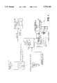
- FIG. 1is an overall block diagram of the motorized biopsy needle positioner of the present invention.
- FIG. 2is a pictorial diagram illustrating the biopsy needle positioning mechanism employed in the motorized biopsy needle positioner of FIG. 1.
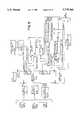
- FIG. 3is a detailed block diagram of the biopsy needle positioning motor controller of FIG. 1.
- FIG. 4is a pictorial diagram of the operator hand controller of FIG. 1.
- FIG. 5is a detailed block diagram of circuitry employed in the operator hand controller of FIGS. 1 and 4.
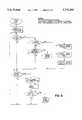
- FIG. 6is a flow chart of the software program executed by the biopsy needle positioning motor controller of FIGS. 1 and 3.
- FIG. 7is a pictorial diagram illustrating a portion of a mammographic needle biopsy system constructed in accordance with the present invention.
- FIG. 8is a pictorial diagram illustrating the patient table of the mammographic needle biopsy system of FIG. 7 as being hinged to facilitate mounting and dismounting by the patient.
- FIG. 9Ais a pictorial diagram illustrating the concave surface of the patient table of FIGS. 7 and 8, as well as a breast aperture in the patient table and an associated diaphragm cover therefor.
- FIG. 9Bis a cross sectional view of a portion of the patient table of FIG. 9A illustrating the positioning of the diaphragm cover between the table base and a padded cover therefor.
- FIG. 9Cis a plan view of the portion of the patient table of FIG. 9A that includes the breast aperture and diaphragm cover.
- FIG. 10is a pictorial diagram of a computer-digitizer console and cursor that are employed with the portion of the mammographic needle biopsy system illustrated in FIG. 7.
- FIG. 11is an electrical block diagram of the computer-digitizer console and cursor of FIG. 10.
- FIG. 12Ais a pictorial diagram illustrating the support and locking mechanism for a film holder arm and an X-ray arm that are part of the portion of the mammographic needle biopsy system illustrated in FIG. 7.
- FIG. 12Ba cross sectional diagram illustrating the details of a tapered bearing support system for the X-ray arm of FIG. 12A.
- FIG. 13is a detailed mechanical diagram of the locking mechanism for the film holder and X-ray arms illustrated in FIGS. 7 and 12A.
- FIGS. 14A-Dare a detailed schematic diagram of circuity employed in the computer-digitizer console and cursor illustrated in the block diagram of FIG. 11.
- FIG. 15is a diagram illustrating the layout of the platen area of the computer-digitizer console of FIG. 10.
- the present inventionis directed to mammographic systems which incorporate motorized positioners for positioning a medical instrument at a point of interest within a patient's breast. It will be appreciated that such a motorized positioner can be incorporated into a variety of mammographic systems. Such a motorized positioner is described below in connection with FIGS. 1-6. Thereafter, a particular embodiment of a mammographic system incorporating a motorized positioner is described in connection with FIGS. 7-15.
- a motorized biopsy needle positionerthat includes a film digitizer and coordinates calculator FDCC, a biopsy needle positioning motor controller BNPMC, a biopsy needle positioning mechanism BNPM, an operator hand controller OHC, and a remote view and display box RVDB.
- the film digitizer and coordinates calculatoroperates to digitize a point of interest in a patient's breast under examination and to thereafter compute and display the three-dimensional or spatial coordinates of the digitized point of interest.
- the inventionwill be described with respect to a polar coordinate system, the three-dimensional or spatial coordinates of the point of interest can be expressed in polar coordinates, an X, Y, and Z rectangular coordinate system or other spatial coordinate system.
- the biopsy needle positioning motor controllerreceives the computed spatial coordinates of an identified point of interest from the film digitizer and coordinates calculator and drives three conventional DC motors that serve to control a puncture instrument in its rotation (horizontal) and angulation (vertical) axes, and to set a stop position along its depth axis to position a biopsy needle or other device retained by the puncture instrument for insertion to the identified point of interest within the patient's breast. It will be appreciated that particular positional adjustments, e.g., the setting of the stop position along the depth axis, can be performed manually in accordance with the present invention
- the biopsy needle positioning mechanismillustrated in the detailed diagram of FIG. 2, and typically employed as a component of an overall mammographic needle biopsy system, comprises a conventional puncture instrument 10 for retaining a biopsy needle or other biopsy or therapeutic delivery device (not illustrated).
- Three conventional DC motors 12, 14, and 16are provided for moving the biopsy needle retained by the puncture instrument 10 in the rotation and angulation axes and for setting a stop position along the depth axis, respectively.
- Positional feedbackis provided to the biopsy needle positioning motor controller by the three DC motors 12, 14, and 16.
- the operator hand controllerallows the clinician user to control the motorized biopsy needle positioning system. Controls are provided to permit the user to initiate movement of the biopsy needle into a position for insertion to the identified point of interest within the patient's breast, in accordance with the computed spatial coordinates of that point of interest.
- the position of the biopsy needlemay be monitored by the user with reference to a 32-character display on the operator hand controller.
- An enable switchis provided to prevent inadvertent motion of the biopsy needle.
- the remote view and display boxreceives the spatial coordinates of rotation, angulation, and depth from the biopsy needle positioning motor controller and displays them for the benefit of the clinician user or others on a 40-character alphanumeric display.
- the remote view and display boxmay be conveniently mounted on a table that includes means for mounting and lighting x-ray reference films to be viewed during a breast; biopsy procedure.
- the biopsy needle positioning motor controllerreceives the spatial coordinates of the identified point of interest within the patient's breast from the film digitizer and coordinates calculator and computes the variables required to drive the three DC motors 12, 14, and 16 that form part of the biopsy needle positioning mechanism. Information regarding the position of the biopsy needle is continuously provided by the biopsy needle positioning motor controller to the LED displays in the operator hand controller.
- the biopsy needle positioning motor controllerreceives commands from the operator hand controller and drives the biopsy needle positioning mechanism in the direction specified for as long as the user simultaneously depresses one of the direction arrow keys and the enable switch located on the operator hand controller illustrated in FIG. 4.
- a central processing unit (8032 CPU) within the biopsy needle positioning motor controllerhas a direct serial communications link with the remote view and display box through an RS422 serial transmitter U29.
- the 8032 CPUalso has two bi-directional communications links through a dual synchronous universal transmitter/receiver DUART, which provides serial communications between the biopsy needle positioning motor controller and both the film digitizer and coordinates calculator (serial channel B) and the operator hand controller (serial channel A).
- the 8032 CPUloads the three DC motor controller sections (rotation, angulation, and depth) with high level initial conditions data.
- This initial conditions dataincludes velocity constants, acceleration constants, PID filter information, and sample period.
- the 8032 CPUreads these spatial coordinates and calculates the corresponding motor control values.
- the 8032 CPUthen sends this data to the three motor control sections.
- the motor control sectionscalculate the actual motor drive voltages and provide the drive voltages to motors 12, 14, and 16 through separate H-bridge circuits.
- the motor control sectionsmonitor the encoder feedback from the biopsy needle positioning mechanism to determine the position of the biopsy needle and to adjust the motor drive voltages as the biopsy needle reaches the identified point of interest.
- a typical motor voltage and velocity profileis trapezoidal in nature, ramping up to a start voltage, then holding constant, and finally ramping down to a stop voltage when the biopsy needle has reached the position required for insertion to the identified point of interest.
- the 8032 CPU support circuitsinclude operating and debug program data in erasable programmable read-only memories EPROMs U1 and U6. Fourteen status bits plus a six-bit DIP switch are monitored through an input port and a random access memory RAM U15. The status bits include +/- limit switches and a home switch associated with each coordinate axis. Two additional status bits serve to monitor the +5-volt (+5ENC) and +24-volt (+24VOK) power supplies.
- a reset circuit U23provides a reset signal to reset the 8032 CPU when power is initially applied. The reset circuit also monitors program execution by counting a pulse associated with each cycle of the program and by executing a CPU reset command if the pulses stop, as may occur during a software lockup.
- the operator hand controller of FIG. 4transmits data to and receives data and instructions from the biopsy needle positioning motor controller via an RS422 serial transmitter/receiver bus (serial channel A). While the operator hand controller is described herein as being a hand-held unit, it may also comprise a console or table mounted unit. The principal functions of the operator hand controller are to 1) transmit switch closure data resulting from actuation of the direction arrow keys and the MANUAL, OFFSET, and TARGET keys to the biopsy needle positioning motor controller; 2) illuminate button LEDs in accordance with information received from the biopsy needle positioning motor controller; and 3) display the spatial coordinates of the identified point of interest within the patient's breast, as provided by the biopsy needle positioning motor controller.
- the operator hand controllerprovides a safety interlock through the ENABLE switch SW9, which must be simultaneously depressed by the user with a selected one of the function keys in order to initiate any of the functions of the operator hand controller.
- the ENABLE switchis mounted on the side of the operator hand controller and, when depressed, energizes a relay in the biopsy needle positioning motor controller that enables movement of the biopsy needle positioning mechanism. When this switch opens, the relay removes power from the three DC motors 12, 14, and 16 of the biopsy needle positioning mechanism.
- the clinician userinitiates control of the biopsy needle positioning mechanism in either an automatic or manual mode by depressing control switches on the operator hand controller.
- Depressing one of the arrow keys or one of the MANUAL, OFFSET or TARGET keyshas the effect of grounding a corresponding input of serial encoder U13.
- serial encoder U13to apply an INTERRUPT 0 (INTOO) to the CPU U9 and place the serial data in 12C protocol on the serial lines SDA and SCL to the CPU U9.
- the CPU U9converts the switch information to RS422 protocol and sends it to the biopsy needle positioning motor controller via serial transmitter U15.
- Each of the keys on the operator hand controllercontains a light emitting diode LED that is illuminated under the control of the biopsy needle positioning motor controller.
- the biopsy needle positioning motor controllerselects a particular LED to be illuminated, sets the brightness of that LED, and determines how long that LED is to remain illuminated. This information is sent to the CPU U9 via serial receiver U15. The CPU U9 then places the information in 12C protocol on the serial lines SDA and SCL to be transmitted to serial decoder/driver U14. Serial decoder/driver U14 pulls a corresponding output to its low state, thereby illuminating the selected LED.
- the CPU U9controls the brightness of the LEDs on the operator hand controller by setting the duty cycle of BRIGHTNESS (BL) pulses applied to the LEDS. A 50% duty cycle illuminates the LEDs at half brightness and a 100% duty cycle illuminates the LEDs at full brightness.
- BRIGHTNESSBL
- the position readout displays U1-U8 in the operator hand controllerprovide two rows of displayed information comprising 16 ASCII characters in each row. Each row comprises four display devices, and each display device contains four 5 ⁇ 7 dot matrix character displays.
- the top line of the position readout displayindicates target number 2 (2:), a rotation axis angle of 10.32 degrees right (10.32R), and an angulation axis angle of 9.72 degrees up (9.72U).
- the bottom line of the position readout displayindicates a depth stop setting of 135.6 millimeters (135.6 mm depth).
- the biopsy needle positioning motor controllersimilarly controls the position readout displays through serial communications with the operator hand controller CPU U9.
- the CPU U9provides segment selection control and character display using two data buses DD0-DD7 and DA0-DA4. To display a selected ASCII character, the CPU U9 puts data describing the character on the DD0-DD7 (P3.0-P3.6 outputs of the CPU U9) bus. The CPU U9 transmits a low signal ENABLE (DWR) to segment decoder U10, which decodes bits DA2-DA4 and applies a low enable signal to the appropriate ones of display device U1-U8. The enabled display device then decodes the character select bit DA1 and DA1 to select the character position which displays the ASCII character defined by data bus DD0-DD6. As with the LEDs, the biopsy needle positioning motor controller defines the brightness of the position readout display. The biopsy needle positioning motor controller communicates the brightness level to the CPU U9, which then switches the BRIGHTNESS (BL) signal on and off, producing the designated duty cycle.
- BLBRIGHTNESS
- FIG. 6there is shown a flow chart of the principal software program performed by the biopsy needle positioning motor controller. All of the software represented by the flow chart of FIG. 6 is stored in EPROMs U1 and U6 of the biopsy needle positioning motor controller and is conventionally written in 8051 assembly language. In accordance with block 1 of the flow chart, the software performs several tasks on initialization of the motorized biopsy needle positioner.
- the reset circuit U23 within the biopsy needle positioning motor controllerapplies a CPU reset pulse to the 8032 CPU (U18). This reset pulse drives the 8032 CPU to its initialization routine.
- the 8032 CPUinitiates power on reset diagnostics (PRD) which are a series of low level tests of the system hardware to determine whether or not the hardware is working well enough to permit operation to continue. If the power on diagnostics are executed successfully, the 8032 CPU begins performing a number of hardware and software initialization tasks.
- PRDpower on reset diagnostics
- the 8032 CPUchecks the condition of the key state byte sent by the operator hand controller via serial communication channel A and stored in RAM U15. If the operator hand controller has sent an INTO byte indicating that a key has been depressed, the software branches to interrogation block 4. If no keys have been depressed, the software increments to interrogation block 10.
- the 8032 CPUchecks the key state byte stored in RAM U15 to determine if the key depressed is the TARGET key. If so, the software branches to routine block 5. If the TARGET key has not been depressed, the software increments to interrogation block 8.
- the 8032 CPUsends a request for the spatial coordinates of the identified point of interest within the patient's breast to the film digitizer and coordinates calculator via serial communications channel B and through DUART U20.
- the softwarethen increments to routine block 6.
- the film digitizer and coordinates calculatorresponds to a request for spatial coordinates by sending a formatted data package containing those spatial coordinates. This data package is automatically stored in the XDATA buffer section of RAM U15. The software then increments to routine block 7.
- the 8032 CPUinitiates position display on the operator hand controller by storing the data package containing the spatial coordinates of the identified point of interest in the XDATA buffer of RAM U15.
- the main programinitiates transfer of the first character of the display, via serial data communications channel A, and then turns the data transfer task over to an interrupt handler subroutine which completes transfer of the remaining 31 characters of displayed information.
- the softwareincrements to interrogation block 10.
- the 8032 CPUchecks the key state byte from the operator hand controller to determine if one of the direction arrow keys or the OFFSET key has been depressed, thereby requiring movement of the biopsy needle positioning mechanism. If so, the software branches to routine block 9. If not, the software increments to interrogation block 10.
- the 8032 CPUloads "go to" data in the motor control circuits for each of the rotation, angulation, and depth axes of the biopsy needle positioning mechanism that represents the current identified point of interest within the patient's breast.
- the 8032 CPUissues start and enable commands to the smart motor controllers U16 and U17.
- the programthen increments to interrogation block 10.
- the softwaremonitors the feedback position data from the smart motor controllers U16 and U17 to determine if the biopsy needle positioning mechanism is moving. If no movement is detected, the software branches back to the beginning of the main program loop at interrogation block 3, and the 8032 CPU issues a program loop pulse to the reset circuit. If movement of the biopsy needle positioning mechanism is detected, the program branches to routine block 11.
- the programmonitors the motor position data from the smart motor controllers U16 and U17 on each axis.
- the new position datais loaded into the XDATA buffer in RAM U15 and the first character is transferred to the operator hand controller via serial communications channel A by the main program.
- the remaining charactersare then transferred by the interrupt handler subroutine.
- the programthen increments to routine block 12.
- the programchecks all status and error information to determine 1) whether any axis has reached a soft limit; 2) whether any axis has reached a hard limit; or 3) whether any current limit been reached.
- the smart controller statusis checked to determine 1) whether an excessive position error exists; 2) whether a wraparound error has occurred; or 3) whether an index (center 0) has been detected. The program then increments to interrogation block 13.
- the 8032 CPUcompares current position data to the coordinates of the identified point of interest to determine if the biopsy needle positioning mechanism is properly positioned for insertion of the biopsy needle to the identified point of interest. If it is not at the correct position, the program loops back to interrogation block 3 and the 8032 CPU issues a program loop pulse to the reset circuits. If the biopsy needle positioning mechanism has reached the target position, the program branches to routine block 14.
- the 8032 CPUissues a status byte to the smart motor controllers U16 and U17 for each axis, causing the motors to stop.
- the programthen loops back to interrogation block 3, and the 8032 CPU issues a program loop pulse to the reset circuits.
- the software flowcharted in FIG. 6controls the high level modes of operation of the motorized biopsy needle positioner of the present invention.
- These modes of operationinclude the JOG mode that enable manual control of the motion of the biopsy needle, the HOME mode that places the biopsy needle in the HOME position, the TARGET mode that drives the biopsy needle into position for insertion to the identified point of interest within the patient's breast, the OFFSET mode that drives the biopsy needle into position for insertion to a point within the patient's breast that is spatially offset from the identified point of interest, and the ERROR mode in which certain error messages are visually displayed to the user.
- the software flowcharted in FIG. 6performs motion control by receiving commands from the mode control logic, by generating commands to the smart motor controllers U16 and U17 within the biopsy needle positioning motor controller, and by monitoring status during movement of the biopsy needle positioning mechanism.
- the current motor positions and status informationis updated as required for the mode control logic to track the movement of the biopsy needle positioning mechanism.
- the softwareperiodically sends messages for display on the remote view and display box. These messages are collected by the interrupt service routine and stored in RAM U15.
- the clinician userinitiates a breast biopsy procedure by employing the film digitizer and coordinates calculator to digitize an identified point of interest within the patient's breast and to then compute the spatial coordinates of that identified point of interest.
- the computed spatial coordinatesappear in the displays of the film digitizer and coordinates calculator, the remote view and display box, and the operator hand controller.
- the userthen employs the operator hand controller to automatically set the biopsy needle positioning mechanism such that the biopsy needle retained therein is precisely positioned for insertion to the identified point of interest by simultaneously depressing the ENABLE and TARGET keys on the operator hand controller.
- the usermay wish to take a biopsy of the surrounding tissue.
- Offsets1 to 20 millimeters, in 1-millimeter increments, may be entered by the user.
- the useremploys the film digitizer and coordinates calculator to place the mouse on one of the stereotactic images of the patient's breast and moves the crosshairs of the mouse above, below, to the right, or to the left of the identified point of interest.
- the userclicks the mouse button once for each millimeter of offset desired in that direction.
- the three displaystrack the offset entered by the user and display the number of millimeters of offset.
- the usermust simultaneously depress the ENABLE and OFFSET keys on the operator hand controller to move the biopsy needle positioning mechanism to the offset location. After that biopsy is completed, the user may enter a new offset and repeat the above procedure to obtain a biopsy at another point that is also spatially offset from the original identified point of interest. Alternatively, the biopsy needle positioning mechanism may be returned to the position required for insertion of the biopsy needle to the original identified point of interest by simultaneously depressing the ENABLE and TARGET keys of the operator hand controller.
- the usermay disregard the identified point of interest and instead select a manual mode of operation to move the biopsy needle positioning mechanism as desired by first simultaneously depressing the ENABLE and MANUAL keys of the operator hand controller. This enables the four directional arrow keys of the operator hand controller, which may then be actuated to provide manual control of the rotation and angulation axes of the biopsy needle positioning mechanism. The user simultaneously depresses the ENABLE key and one of the directional arrow keys to drive the biopsy needle positioning mechanism in the desired direction. The three displays track this movement to provide a visual display of the movement of the biopsy needle positioning mechanism as it occurs. To return the biopsy needle positioning mechanism to the position required for insertion of the biopsy needle to the original identified point of interest within the patient's breast under examination, it is only necessary for the user to simultaneously depress the ENABLE and TARGET keys.
- FIG. 7there is shown a portion of a mammographic needle biopsy system constructed in accordance with the present invention which incorporates a positioning mechanism such as described above.
- the systemcomprises a pedestal base 110, a patient table 120, a film holder arm 130, and an X-ray arm 140.
- Pedestal base 110houses conventional electromechanical devices for selectively raising and lowering patient table 120, film holder arm 130, and X-ray arm 140.
- patient table 120, film holder arm 130, and X-ray arm 140may be arranged for adjustable inclination from the horizontal to permit medical personnel more working space in which to maneuver film holder arm 130 and X-ray arm 140 beneath patient table 20.
- Film holder arm 130is supported at one end thereof by an arm carrier 124 and is arranged to pivot radially in a horizontal plane about its connection point to arm carrier 124.
- X-ray arm 140is also supported at one end thereof by arm carrier 124 below and in vertical alignment with film holder arm 130 and is also arranged to pivot radially in a horizontal plane about its connection point to arm carrier 124.
- Primary positions of the film holder arm 130 and X-ray arm 140are represented by radial movement of plus or minus 90 degrees from the longitudinal axis of patient table 120.
- Primary detentsare provided to lock film holder arm 30 and X-ray arm 140 at their -90, -45, 0, +45, and +90 degree primary positions. Secondary detents are provided to lock the X-ray arm 140 at positions which represent radial motion of plus or minus 15 degrees from each primary position for stereoscopic imaging, as well as at the 0 degree position for general mammography. Independent or simultaneous radial movement of both the film holder arm 130 and the X-ray arm 140 is controlled by locking handles 152 and 154 located beneath X-ray arm 140.
- a film holder 126is mounted on top of film holder arm 130 proximate the pivot point thereof.
- FIGS. 12A-B and 7there is shown a support plate 156 attached to arm carrier, 124.
- a tapered roller bearing assembly 158resides within support plate 156 and receives a shaft 160 on which X-ray arm 140 is supported for radial motion.
- a similar tapered roller bearing assemblyresides within a support plate 162 and also receives shaft 160 on which film holder arm 130 is supported for radial motion above X-ray arm 140.
- the use of tapered roller bearingsresults in substantial elimination of undesirable backlash and play in the support of film holder arm 130 and X-ray arm 140 and thereby increases the overall accuracy of the mammographic needle biopsy system.
- a circular detent plate 164includes a number of wedge-shaped detents 166 spaced around its periphery to lock the film holder arm 130 and X-ray arm 140 into the positions referenced above.
- An arm assembly lock 168serves to lock radial motion in concert of film holder arm 130 and X-ray arm 140.
- Arm assembly lock 168includes a stationary plate 169 mounted to the underside of arm carrier 124.
- a locking dog 170includes an elongated wedge-shaped opening 172 at a pivot end thereof and a lock tab 174 at the other end thereof. Lock tab 174 is wedge-shaped to provide precise mating engagement with wedge-shaped detents 166 around the periphery of circular detent plate 164.
- a spring 176urges wedge-shaped lock tab 174 into complete engagement with a selected one of wedge-shaped detents 166.
- a spring 178urges the sides of elongated wedge-shaped opening 172 at the pivot end of locking dog 170 into engagement with a circular pivot pin 180 mounted on stationary plate 169.
- a lever 182, hingedly connected to locking dog 170,is controlled by handle 154 to move wedge-shaped lock tab 174 out of engagement with one of the wedge-shaped detents 166 to permit radial (motion in concert of film holder arm 130 and X-ray arm 140.
- An X-ray arm lock 184is mounted to the underside of X-ray arm 140 and diametrically positioned with respect to arm assembly lock 168, a locking dog 186, similar in shape to locking dog 170, includes an elongated wedge-shaped opening 188 at a pivot end thereof and a lock tab 190 at the other end thereof.
- Lock tab 190is wedge-shaped to provide precise mating engagement with wedge-shaped detents 166 spaced around the periphery of circular detent plate 164.
- a spring 192urges wedge-shaped lock tab 190 into complete engagement with a selected one of wedge-shaped detents 166.
- a spring 194urges the sides of elongated wedge-shaped opening 188 at the pivot end of locking dog 186 into engagement with a circular pivot pin 196 mounted on the underside of X-ray arm 140.
- a lever 197is hingedly connected at pivot point 198 to the underside of X-ray arm 140 and is controlled by either of handles 152 that extend outwardly of the sides of X-ray arm 140 to move wedge-shaped lock tab 190 out of engagement with one of the wedge-shaped detents 166 to permit radial motion of X-ray arm 140 independent of film holder arm 130.
- wedge-shaped detents 166 on circular detent plate 164together with precisely mating wedge-shaped lock tabs 174 and 190 that engage therewith results in backlash free locking of film holder arm 130 and X-ray arm 140 to significantly increase the overall accuracy of the mammographic needle biopsy system.
- a compression paddle 128is slidably mounted outwardly from film holder 126 on top of film holder arm 130 and is employed to compress the patient's pendulant breast protruding through an aperture in patient table 120 against film holder 126 preparatory to taking stereoscopic X-ray views thereof. Sliding motion of compression paddle 128 may be controlled manually or by a footswitch coupled to a conventional motorized mechanism. An automatic compression control, which adjustably limits the amount of breast compression, may be provided.
- a puncture instrument assembly 132 for retaining a biopsy needle 134is mounted on top of film holder arm 130 outwardly from compression paddle 128. Puncture instrument assembly 132 is mounted to film holder arm 130 in a conventional manner by means of horizontal and vertical stages whose angular positioning can be automatically controlled as described above in connection with FIGS. 7-12.
- a depth scale and depth stopper forming part of puncture instrument assembly 132control the depth to which biopsy needle 134 is inserted into the compressed pendulant breast of the patient during an examination procedure. At least some of the horizontal angle, vertical angle, and insertion depth parameters that define the point of interest within the patient's breast to which biopsy needle 134 is to be inserted are thus automatically set thereby reducing the opportunity for human error.
- Biopsy needle 134is conventionally manually inserted into the patient's breast following setting of the proper angle and depth parameter values. However, as the tip of biopsy needle 134 approaches tumorous tissue within the breast, that tissue may tend to move as the needle slowly approaches.
- puncture instrument assembly 132may comprise a conventional spring-loaded biopsy gun for rapidly inserting a biopsy needle to a specific point of interest within the patient's breast.
- the spring-loaded biopsy gunmay comprise, for example, the BIOPTY gun marketed by the Bard Urological Division of C.R. Bard, Inc, Covington, Ga.
- a conventional X-ray tube assemblyis mounted on top of X-ray arm 140 at the outward end thereof and is arranged to direct an X-ray beam in horizontal alignment with the patient's compressed pendulant breast onto an X-ray film retained within X-ray film holder 126.
- patient table 120includes a hinged foot portion 144 illustrated in a lowered position to facilitate mounting and dismounting by the patient.
- the foot portion of patient table 120is raised to the horizontal position illustrated in FIG. 7.
- the foot portion 144 of patient table 120is lowered to the position shown in FIG. 8 following the examination procedure to facilitate dismounting by the patient.
- Control of the position of foot portion 144 of patient table 120may be accomplished via any of a number of conventional manual or motorized mechanisms.
- FIG. 9Athere is shown the patient table 120 of FIGS. 7 and 8 formed to be concave in shape along the longitudinal axis thereof to permit examination of the patient's breast tissue that is adjacent the chest wall.
- a pad 150covers-table 120 to provide a comfortable surface on which to lie.
- a breast aperturethrough which one of the patient's breasts is permitted to pendulantly protrude.
- table 120may have a generally flat surface on which the patient lies, but includes a dish-shaped area around the breast aperture to permit examination of the patient's breast tissue that is very near her chest wall.
- a diaphragm cover 146is provided that may be rotated within the breast aperture to selectively cover a desired portion thereof so that only a selected one of the patient's breasts protrudes through the breast aperture.
- Diaphragm cover 146is illustrated in 20 more detail in FIGS. 9B and 9C to include a flange 148 that secures diaphragm cover 146 in place over the breast aperture in patient table 120. Flange 148 is retained between table 120 and pad 150.
- Computer-digitizer console 200includes a platen area 204 having a light box viewing area 206 over which two stereoscopic X-ray images 208, 210 are positioned for viewing and digitizing. Platen area 204 also includes a function control area 212 for selecting certain functions to be performed by computer-digitizer console 200.
- Computer-digitizer console 200includes a printer 214 for providing a printed record of the vertical angle, horizontal angle, and depth parameters of a point of interest 209 depicted on the two stereoscopic X-ray images 208, 210 and an alphanumeric information display 216 for visually displaying alphanumeric function information selected from function control area 212 of platen area 204, as well as other alphanumeric messages.
- Cursor 202is employed on platen area 204 and comprises a one-button mouse with crosshairs that enables the user to select specific functions specified within function control area 212 of platen area 204 and to digitize a point of interest 209 depicted on the two stereoscopic X-ray images 208, 210 of the patient's breast.
- Computer-digitizer console 200is operative for analyzing the relative positions of two stereoscopic images 208, 210 taken from two angles and for determining the location in 3-dimensional space of a point of interest 209 shown on the two stereoscopic images 208, 210.
- computer-digitizer console 200is operative for automatically calculating the vertical angle, horizontal angle, and depth of insertion parameters necessary to direct a biopsy needle 134 retained by puncture instrument assembly 132 of FIG. 7 to the point of interest 209 within the patient's breast.
- the calculations which are madeare based on straightforward analytical geometry, and the routines and subroutines of instructions that are executed by computer-digitizer console 200 to perform these calculations are detailed in the firmware listing that follows this specification.
- the plus and minus 15 degree stereo anglecauses the apparent position of an object to translate only in the horizontal plane, never in the vertical plane,
- a straightedge placed between a pair of projected reference marks I11, 113 on each X-ray image 208, 210easily defines the horizontal plane to assist in film evaluation.
- These reference marksare projected with a parallax error in both the X and Y directions because they are not in direct contact with the film but are spaced approximately 10 millimeters away from the film. This parallax error is corrected by way of correction routines executed by computer-digitizer console 200.
- the general mathematical technique for aligning an image with a digitizeris to develop a transformation matrix that can accept an input vector defined by the raw X and Y coordinates of the point of interest as determined by the digitizer. These raw coordinates are then transformed mathematically to an output vector defined in terms of X and Y coordinates relative to the system coordinates 0,0 of the two stereoscopic X-ray images 208, 210.
- the transformation matrixis the result of successively applying translate, rotate, and scale operators to an identity matrix.
- the first step in building this transformation matrixis to use knowledge of the location, relative to the film and X-ray source, of the two registration marks 211, 213 projected onto each of the two stereoscopic X-ray images 208, 210.
- the parallel error in the X directionis calculated for both the left and right reference marks 211, 213 and Is applied to shift the reference marks 211, 213 to their true locations.
- Other points appearing on the two stereoscopic X-ray images 208, 210may now be digitized relative to the two reference marks 211, 213.
- Parallax errorsare subtracted to determine the true locations of the reference marks 211, 213 so that a point between them can be located.
- any digitized point on the two stereoscopic X-ray images 208, 210is manipulated by the transformation matrix to produce the X and Y coordinates of that point relative to location 0,0 on the images. Thereby, the raw digitizer coordinates are transformed into film coordinates.
- the coordinates of the endpoints of two linesare known. These lines are the two rays that began at the focal point of the X-ray, travelled through the patient's breast, and ended on the surface of the X-ray film. The equation for the intersection of these lines must then be solved. Since the endpoints of these two lines are measured with respect to the same reference, the point of intersection in X, Y, Z space is determined analytically using standard principles of analytical geometry.
- Puncture instrument assembly 132 of FIG. 7provides horizontal angle, vertical angle, and insertion depth control of biopsy needle 134 mounted therein.
- the location of the rotational isocenter of puncture instrument assembly 132is known in the X, Y, and Z directions. It is therefore easy to "draw" a line between this rotational isocenter or pivot point and the point of interest 209 shown on the two stereoscopic X-ray images 208, 210.
- the projection of this line in the X-Z planeis the horizontal coordinate.
- the other coordinateis vertical and is obtained from the projection of this line in the Y-Z plane, with the exception that the biopsy needle does not radiate from the pivot point.
- the angle between the horizontal and vertical coordinatesIs known as the beta angle.
- a right trianglecan be "drawn” using the Y-Z projection and the amount of the needle offset.
- the third side of this right trianglerepresents the total distance to the point of interest 209 shown on the two stereoscopic X-ray images 208, 210 of the patient's breast and is used to set the depth to which biopsy needle 134 is to be inserted into the breast to locate the point of interest 209.
- the angle between the third side of the right triangle and the Y-Z projectionis subtracted from the angle beta to determine the elevation or vertical angle.
- the axis of biopsy needle 134could be positioned in the same plane as that of the pivot point to avoid the calculations required to take into account any offset distance between the axis of the biopsy needle 134 and the pivot point.
- the determinations of horizontal and vertical anglesare subject to a final correction to account for slight angular errors in aligning the positioners for puncture instrument assembly 132.
- the determined depth settingtakes into account the length of the biopsy needle 134 and of the needle holder of puncture instrument assembly 132.
- Digitizer 300may comprise a Model 2200 digitizer manufactured by Numonics, Inc. Digitizer 300 includes a platen 204 that is backlit for viewing two stereoscopic X-ray images 208, 210 of the patient's breast for purposes of digitizing a point of interest 209 depicted on the two stereoscopic X-ray images 208, 210. Cursor 202 may comprise, for example, a one-button mouse with crosshairs, also manufactured by Numonics, Inc. Alphanumeric information display 216 may comprise a flip 2 ⁇ 20 vacuum fluorescent display manufactured by IEE.
- Printer 214may comprise a Model STP211-192 printer and associated interface circuitry manufactured by Seiko.
- a conventional power supply 218supplies +5, +12 and -12 volts to power digitizer 300, alphanumeric information display 216, printer 214, and a computer and digitizer interface circuit 220.
- Computer and digitizer interface circuit 220comprises the circuitry shown in the detailed schematic diagram of FIGS. 14A-D.
- computer and digitizer interface circuit 220includes a central processing unit or CPU 122 that may comprise an off-the-shelf intel 8031 microprocessor.
- a pair of PROMS 224, 226 that may each comprise a 32K ⁇ 8 PROM such as the T127256serve to store the routines and subroutines of instructions detailed in the firmware listing that follows this specification.
- These routines and subroutines of instructionsare executed by CPU 222 to calculate the vertical angle, horizontal angle, and insertion depth parameters necessary to direct biopsy needle 134 of FIG. 7 to a precise point of interest within a patient's breast.
- a random access memory or RAM 228provides temporary storage of data and other information during execution by CPU 222 of the routines and subroutines of instructions stored in PROMS 224, 226.
- RAM 228may comprise, for example, a Hitachi 62565 32K ⁇ 8 RAM.
- a system clock 230may comprise any of a number of commercially available clock chips, such as the Signetics PCF8573 real time clock chip.
- a non-volatile electrically erasable (EE) ROM 232that may comprise a Xicor X2404 EE ROM, serves to store calibration data and setup and adjustment parameters relating to the particular mammographic needle biopsy system in which it resides.
- a line driver 234that may comprise a National Semiconductor DS8921A RS422 line driver, serves to interface computer and digitizer interface circuit 220 to a conventional remote display (not illustrated) that may be positioned adjacent patient table 120 of FIG. 7 to permit the operator of the mammographic needle biopsy system to view two stereoscopic X-ray images of the patient's breast from his or her operating position.
- a buffer 238, that may comprise a Texas Instruments 74LS245 buffer chip, and a connector 240serve to interface computer and digitizer interface circuit 220 to alphanumeric information display 216 located in computer-digitizer console 200 of FIG. 10.
- another buffer 242, that may comprise a Texas Instruments 74LS374 buffer chip, and a connector 244serve to interface computer and digitizer interface circuit 220 to printer 214.
- the function control area 212 of platen area 204includes a control function menu, the individual functions of which are selected using cursor 202.
- the crosshairs of cursor 202are positioned over that selected function and the button on cursor 202 is clicked.
- a series of prompts displayed on alphanumeric information display 216requests information regarding the left reference mark 211, the right reference mark 213, and the point of interest 209 depicted on stereoscopic X-ray image 208.
- the operatoraligns the crosshairs of cursor 202 over the left and right reference marks 211, 213, clicking the button of cursor 202 over each reference mark.
- the operatoris then prompted to enter the corresponding information from stereoscopic X-ray image 210.
- the message DATA ENTRY COMPLETEDis displayed on alphanumeric information display 216.
- the SELECT NEEDLE function shown on function control area 212allows the operator to choose the appropriate biopsy needle for specific depth calculations. Several localizations on a single point of interest 209 may be performed using biopsy needles of different lengths by alternately selecting the SELECT NEEDLE and CALCULATE TARGET functions. Selecting the SELECT NEEDLE function cycles through five choices of biopsy needles.
- the CALCULATE TARGET function shown on function control area 212initiates automatic computation by computer-digitizer console 200 of the vertical angle, horizontal angle, and insertion depth parameters defining point of interest 209. These results are then displayed on alphanumeric information display 216 and remain displayed until the button of cursor 202 is clicked to select another function.
- the PRINT DATA function shown on function control area 212initiates printing of the calculated values of the vertical angle, horizontal angle, and insertion depth parameters on printer 214.
- the ADVANCE PAPER function shown on function control area 212advances the paper on printer 214 for the period of time during which the button on cursor 202 is depressed.
- the BACK UP function shown on function control area 212allows the operator to reenter the previous item of data during a data entry sequence.
- the CANCEL function shown on function control area 212cancels the present operation being performed by computer-digitizer console 200 and returns the system to an idle mode.
- Computer-digitizer 200is also operative for displaying a number of error codes on alphanumeric information display 216.
- the WRONG ORDER FOR IMAGE POINTS error codeis displayed when the operator attempts to enter data via cursor 202 from stereoscopic X-ray image 210 before entering the appropriate data from stereoscopic X-ray image 208,
- the BAD ORIENTATION OF FILM FOR DIGITIZING error codeis displayed when either of the two stereoscopic X-ray images 208, 210 Is mounted on digitizer viewing area 206 in a position such that reference marks 211, 213 are rotated more than 45 degrees from the X axis.
- the REF MARKS MORE THAN 2.0 MM OFF error codeis displayed when an error has been made in locating the reference marks 211, 213 on either of the two stereoscopic X-ray images 208, 210 using cursor 202.
- the OVERFLOW IN MATH ROUTINES error codeis displayed in the case of an internal program execution error and should never be observed.
- the NOT ALL DATA POINTS TAKEN error codeis displayed when the operator omits one of the six points of data depicted on the two stereoscopic X-ray images 208, 210 during the data entry operation. When this error code appears, the operator must re-initiate the data entry sequence using the DATA ENTRY function shown on function-control area 212.
- ERROR READING TIME & DATE CLOCKthe ERROR WRITING TIME & DATE CLOCK
- ERROR VERIFYING TIME & DATE CLOCK error codesare displayed whenever there is a hardware problem with the real time clock 230.
- the ERROR READING EEPROM and ERROR WRITING EEPROM error codesare displayed whenever there is a problem with the non-volatile set-up memory EEPROM 232.
- the BAD EEPROM CHECKSUM-DEFAULTS LOADED error codeis displayed whenever a problem is detected with a checksum calculation that occurs when data is written to the EEPROM.
- the mammographic needle biopsy system of the present inventionfunctions in accordance with the principle that a tumor which is photographed by X-ray from separate angles relative to the normal of the film plane is projected in different positions on the X-ray film. The coordinates of these projections can then be measured in relation to a pair of crosshairs projected onto the film as the X-ray photographs are being taken. By using standard analytical geometry relationships, the position of a tumor can be calculated very precisely. A puncture instrument assembly is then used to position the tip of a hollow biopsy needle at the center of the tumor, thereby allowing the operator to extract a sample of the tumorous tissue.
- the tip of the hollow needlecan be manually positioned within the breast and then the puncture instrument assembly can be used to drive the needle tip to the location of interest. This procedure can be performed with an accuracy of better than 1.0 mm.
- the system of the present inventionrecognizes coordinates of the suspected tumor as X, Y, and Z values it translates these coordinates to vertical angle, horizontal angle, and insertion depth parameter values prior to their being visually displayed or printed for the operator.
Landscapes
- Health & Medical Sciences (AREA)
- Life Sciences & Earth Sciences (AREA)
- Engineering & Computer Science (AREA)
- Surgery (AREA)
- Medical Informatics (AREA)
- Public Health (AREA)
- General Health & Medical Sciences (AREA)
- Animal Behavior & Ethology (AREA)
- Biomedical Technology (AREA)
- Veterinary Medicine (AREA)
- Molecular Biology (AREA)
- Heart & Thoracic Surgery (AREA)
- Pathology (AREA)
- Nuclear Medicine, Radiotherapy & Molecular Imaging (AREA)
- Physics & Mathematics (AREA)
- Radiology & Medical Imaging (AREA)
- Optics & Photonics (AREA)
- High Energy & Nuclear Physics (AREA)
- Biophysics (AREA)
- Oral & Maxillofacial Surgery (AREA)
- Dentistry (AREA)
- Signal Processing (AREA)
- Multimedia (AREA)
- Neurosurgery (AREA)
- Apparatus For Radiation Diagnosis (AREA)
Abstract
Description
Claims (24)
Priority Applications (1)
| Application Number | Priority Date | Filing Date | Title |
|---|---|---|---|
| US08/485,442US5735264A (en) | 1989-11-21 | 1995-06-07 | Motorized mammographic biopsy apparatus |
Applications Claiming Priority (6)
| Application Number | Priority Date | Filing Date | Title |
|---|---|---|---|
| US07/440,775US5078142A (en) | 1989-11-21 | 1989-11-21 | Precision mammographic needle biopsy system |
| US07/799,418US5240011A (en) | 1991-11-27 | 1991-11-27 | Motorized biopsy needle positioner |
| US81772292A | 1992-01-07 | 1992-01-07 | |
| US08/018,805US5415169A (en) | 1989-11-21 | 1993-02-17 | Motorized mammographic biopsy apparatus |
| US08/428,563US5803912A (en) | 1989-11-21 | 1995-04-25 | Positioning function mammographic biopsy function system with offset |
| US08/485,442US5735264A (en) | 1989-11-21 | 1995-06-07 | Motorized mammographic biopsy apparatus |
Related Parent Applications (3)
| Application Number | Title | Priority Date | Filing Date |
|---|---|---|---|
| US07/799,418Continuation-In-PartUS5240011A (en) | 1989-11-21 | 1991-11-27 | Motorized biopsy needle positioner |
| US81772292AContinuation-In-Part | 1989-11-21 | 1992-01-07 | |
| US08/018,805ContinuationUS5415169A (en) | 1989-11-21 | 1993-02-17 | Motorized mammographic biopsy apparatus |
Publications (1)
| Publication Number | Publication Date |
|---|---|
| US5735264Atrue US5735264A (en) | 1998-04-07 |
Family
ID=27486782
Family Applications (4)
| Application Number | Title | Priority Date | Filing Date |
|---|---|---|---|
| US08/018,805Expired - LifetimeUS5415169A (en) | 1989-11-21 | 1993-02-17 | Motorized mammographic biopsy apparatus |
| US08/428,563Expired - Fee RelatedUS5803912A (en) | 1989-11-21 | 1995-04-25 | Positioning function mammographic biopsy function system with offset |
| US08/485,442Expired - LifetimeUS5735264A (en) | 1989-11-21 | 1995-06-07 | Motorized mammographic biopsy apparatus |
| US09/148,349Expired - LifetimeUS6022325A (en) | 1989-11-21 | 1998-09-04 | Mammographic biopsy apparatus |
Family Applications Before (2)
| Application Number | Title | Priority Date | Filing Date |
|---|---|---|---|
| US08/018,805Expired - LifetimeUS5415169A (en) | 1989-11-21 | 1993-02-17 | Motorized mammographic biopsy apparatus |
| US08/428,563Expired - Fee RelatedUS5803912A (en) | 1989-11-21 | 1995-04-25 | Positioning function mammographic biopsy function system with offset |
Family Applications After (1)
| Application Number | Title | Priority Date | Filing Date |
|---|---|---|---|
| US09/148,349Expired - LifetimeUS6022325A (en) | 1989-11-21 | 1998-09-04 | Mammographic biopsy apparatus |
Country Status (1)
| Country | Link |
|---|---|
| US (4) | US5415169A (en) |
Cited By (120)
| Publication number | Priority date | Publication date | Assignee | Title |
|---|---|---|---|---|
| US6045640A (en)* | 1997-09-01 | 2000-04-04 | Georg Fischer Rohrleitungssysteme Ag | Apparatus for butt welding of articles made of thermoplastic material |
| WO2000025692A1 (en)* | 1998-11-04 | 2000-05-11 | Trex Medical Corporation | Method and apparatus for removing tissue from a region of interest using stereotactic radiographic guidance |
| US6445332B1 (en)* | 1999-03-11 | 2002-09-03 | Eaton Corporation | Command module for a motor control system |
| US6558337B2 (en)* | 2001-04-17 | 2003-05-06 | Wisconsin Alumni Research Foundation | Positioner for medical devices such as biopsy needles |
| US6603988B2 (en) | 2001-04-13 | 2003-08-05 | Kelsey, Inc. | Apparatus and method for delivering ablative laser energy and determining the volume of tumor mass destroyed |
| US20030194121A1 (en)* | 2002-04-15 | 2003-10-16 | General Electric Company | Computer aided detection (CAD) for 3D digital mammography |
| US20030194050A1 (en)* | 2002-04-15 | 2003-10-16 | General Electric Company | Multi modality X-ray and nuclear medicine mammography imaging system and method |
| US20030194115A1 (en)* | 2002-04-15 | 2003-10-16 | General Electric Company | Method and apparatus for providing mammographic image metrics to a clinician |
| US20030194051A1 (en)* | 2002-04-15 | 2003-10-16 | General Electric | Tomosynthesis X-ray mammogram system and method with automatic drive system |
| US20030194048A1 (en)* | 2002-04-15 | 2003-10-16 | General Electric Company | Reprojection and backprojection methods and algorithms for implementation thereof |
| US20030215057A1 (en)* | 2002-05-15 | 2003-11-20 | General Electric Company | Scatter correction method for non-stationary X-ray acquisitions |
| US6707878B2 (en) | 2002-04-15 | 2004-03-16 | General Electric Company | Generalized filtered back-projection reconstruction in digital tomosynthesis |
| WO2004002289A3 (en)* | 2002-06-26 | 2004-03-25 | Joseph Aferzon | System and method for guiding surgical tools during surgical procedures |
| US20040088791A1 (en)* | 2002-11-08 | 2004-05-13 | Luc Corbeil | Method and apparatus for positioning a patient on a table for a medical procedure on a breast |
| US20040114790A1 (en)* | 2001-01-26 | 2004-06-17 | Keiji Yamamoto | Projection conversion device and method and elapsed-time differential image preparation device and method |
| US20040116914A1 (en)* | 2002-12-12 | 2004-06-17 | Kambiz Dowlatshahi | Apparatus and method for interstitial laser therapy of small breast cancers and adjunctive therapy |
| US20050089205A1 (en)* | 2003-10-23 | 2005-04-28 | Ajay Kapur | Systems and methods for viewing an abnormality in different kinds of images |
| US20050165328A1 (en)* | 2002-03-19 | 2005-07-28 | Norbert Heske | Biopsy device and biopsy needle module that can be inserted into the biopsy device |
| US20050203439A1 (en)* | 2002-03-19 | 2005-09-15 | Norbert Heske | Vacuum biopsy device |
| US20050288549A1 (en)* | 2004-06-14 | 2005-12-29 | Pneumrx, Inc. | Guided access to lung tissues |
| US20050288684A1 (en)* | 2004-06-16 | 2005-12-29 | Aronson Nathan A | Method of reducing collateral flow in a portion of a lung |
| US20060009801A1 (en)* | 2004-07-08 | 2006-01-12 | Mcgurk Erin | Pleural effusion treatment device, method and material |
| US20060025815A1 (en)* | 2004-07-08 | 2006-02-02 | Mcgurk Erin | Lung device with sealing features |
| US20060159318A1 (en)* | 2003-11-26 | 2006-07-20 | Alyassin Abdalmajeid M | Method, system and computer program product for multi-modality registration using virtual cursors |
| US20060167416A1 (en)* | 2004-11-23 | 2006-07-27 | Mark Mathis | Steerable device for accessing a target site and methods |
| US20070221230A1 (en)* | 2006-03-13 | 2007-09-27 | David Thompson | Minimally invasive lung volume reduction device and method |
| US20080045833A1 (en)* | 2006-02-15 | 2008-02-21 | Defreitas Kenneth F | Breast biopsy and needle localization using tomosynthesis systems |
| WO2008020439A2 (en) | 2006-08-17 | 2008-02-21 | Sialo Technology Israel Ltd | All-in-one optical microscopic handle |
| US20080071193A1 (en)* | 2004-07-09 | 2008-03-20 | Claus Reuber | Length Detection System for Biopsy Device |
| US20080185314A1 (en)* | 2007-02-05 | 2008-08-07 | Novian Health, Inc. | Interstitial laser therapy kits |
| US20080188842A1 (en)* | 2007-02-05 | 2008-08-07 | Novian Health, Inc. | Apparatus and methods for delivering ablative laser energy to tissue |
| US20080306406A1 (en)* | 2005-08-10 | 2008-12-11 | C.R. Bard Inc. | Single-Insertion, Multiple Sampling Biopsy Device With Linear Drive |
| US20080319341A1 (en)* | 2005-08-10 | 2008-12-25 | C.R. Bard Inc. | Single-Insertion, Multiple Sample Biopsy Device with Integrated Markers |
| US20090003519A1 (en)* | 2004-11-26 | 2009-01-01 | Kenneth Defreitas | Integrated Multi-Mode Mammography/Tomosynthesis X-Ray System And Method |
| US20090080604A1 (en)* | 2007-08-23 | 2009-03-26 | Fischer Medical Technologies, Inc. | Computed tomography breast imaging and biopsy system |
| US20090118641A1 (en)* | 2007-11-02 | 2009-05-07 | Jacques Van Dam | Devices, Methods, and Kits for a Biopsy Device |
| US20090141859A1 (en)* | 2002-11-27 | 2009-06-04 | Hologic, Inc. | Image Handling and Display in X-Ray Mammography and Tomosynthesis |
| EP1450683A4 (en)* | 2001-11-08 | 2009-11-11 | Univ Johns Hopkins Med | SYSTEM AND METHOD FOR ROBOT TARGETING BY FLUOROSCOPY BASED ON IMAGE ENHANCEMENT |
| US20090296882A1 (en)* | 2002-11-27 | 2009-12-03 | Hologic, Inc. | Image Handling And Display In X-Ray Mammography And Tomosynthess |
| US20090323892A1 (en)* | 2008-06-24 | 2009-12-31 | Georgia Hitzke | Breast Tomosynthesis System With Shifting Face Shield |
| US20100030108A1 (en)* | 2006-10-24 | 2010-02-04 | C.R. Bard, Inc. | Large sample low aspect ratio biopsy needle |
| US20100054400A1 (en)* | 2008-08-29 | 2010-03-04 | Hologic, Inc. | Multi-mode tomosynthesis/mammography gain calibration and image correction using gain map information from selected projection angles |
| US20100135456A1 (en)* | 2002-11-27 | 2010-06-03 | Hologic, Inc. | Full Field Mammography With Tissue Exposure Control, Tomosynthesis, and Dynamic Field of View Processing |
| US20100195882A1 (en)* | 2004-11-15 | 2010-08-05 | Hologic, Inc. | Matching Geometry Generation And Display Of Mammograms And Tomosynthesis Images |
| US20110021946A1 (en)* | 2003-03-29 | 2011-01-27 | C.R. Bard, Inc. | Biopsy needle system having a pressure generating unit |
| US20110054349A1 (en)* | 2007-12-27 | 2011-03-03 | Devicor Medical Products, Inc. | Clutch and valving system for tetherless biopsy device |
| US20110077551A1 (en)* | 2009-09-25 | 2011-03-31 | Videbaek Karsten | Charging station for battery powered biopsy apparatus |
| WO2011053751A3 (en)* | 2009-10-31 | 2011-07-14 | C.R. Bard, Inc. | Biopsy system with infrared communications |
| US8012102B2 (en) | 2005-01-31 | 2011-09-06 | C. R. Bard, Inc. | Quick cycle biopsy system |
| US8131049B2 (en) | 2007-09-20 | 2012-03-06 | Hologic, Inc. | Breast tomosynthesis with display of highlighted suspected calcifications |
| US8251917B2 (en) | 2006-08-21 | 2012-08-28 | C. R. Bard, Inc. | Self-contained handheld biopsy needle |
| US8282574B2 (en) | 2005-08-10 | 2012-10-09 | C. R. Bard, Inc. | Single-insertion, multiple sampling biopsy device usable with various transport systems and integrated markers |
| US8430824B2 (en) | 2009-10-29 | 2013-04-30 | Bard Peripheral Vascular, Inc. | Biopsy driver assembly having a control circuit for conserving battery power |
| US8485989B2 (en) | 2009-09-01 | 2013-07-16 | Bard Peripheral Vascular, Inc. | Biopsy apparatus having a tissue sample retrieval mechanism |
| US8485987B2 (en) | 2006-10-06 | 2013-07-16 | Bard Peripheral Vascular, Inc. | Tissue handling system with reduced operator exposure |
| US8597205B2 (en) | 2007-12-20 | 2013-12-03 | C. R. Bard, Inc. | Biopsy device |
| US8597206B2 (en) | 2009-10-12 | 2013-12-03 | Bard Peripheral Vascular, Inc. | Biopsy probe assembly having a mechanism to prevent misalignment of components prior to installation |
| US8632605B2 (en) | 2008-09-12 | 2014-01-21 | Pneumrx, Inc. | Elongated lung volume reduction devices, methods, and systems |
| US8690793B2 (en) | 2009-03-16 | 2014-04-08 | C. R. Bard, Inc. | Biopsy device having rotational cutting |
| US8708930B2 (en) | 2009-04-15 | 2014-04-29 | Bard Peripheral Vascular, Inc. | Biopsy apparatus having integrated fluid management |
| US8721734B2 (en) | 2009-05-18 | 2014-05-13 | Pneumrx, Inc. | Cross-sectional modification during deployment of an elongate lung volume reduction device |
| US8740921B2 (en) | 2006-03-13 | 2014-06-03 | Pneumrx, Inc. | Lung volume reduction devices, methods, and systems |
| US8787522B2 (en) | 2010-10-05 | 2014-07-22 | Hologic, Inc | Upright x-ray breast imaging with a CT mode, multiple tomosynthesis modes, and a mammography mode |
| US8845548B2 (en) | 2009-06-12 | 2014-09-30 | Devicor Medical Products, Inc. | Cutter drive assembly for biopsy device |
| USD733873S1 (en) | 2013-05-07 | 2015-07-07 | Novian Health Inc. | Probe holder |
| US9173641B2 (en) | 2009-08-12 | 2015-11-03 | C. R. Bard, Inc. | Biopsy apparatus having integrated thumbwheel mechanism for manual rotation of biopsy cannula |
| US9180312B2 (en) | 2005-11-18 | 2015-11-10 | Hologic, Inc. | Brachytherapy device for asymmetrical irradiation of a body cavity |
| US9248311B2 (en) | 2009-02-11 | 2016-02-02 | Hologic, Inc. | System and method for modifying a flexibility of a brachythereapy catheter |
| US9402633B2 (en) | 2006-03-13 | 2016-08-02 | Pneumrx, Inc. | Torque alleviating intra-airway lung volume reduction compressive implant structures |
| US9498175B2 (en) | 2002-11-27 | 2016-11-22 | Hologic, Inc. | System and method for low dose tomosynthesis |
| US9579524B2 (en) | 2009-02-11 | 2017-02-28 | Hologic, Inc. | Flexible multi-lumen brachytherapy device |
| US9623260B2 (en) | 2004-11-05 | 2017-04-18 | Theragenics Corporation | Expandable brachytherapy device |
| US10022557B2 (en) | 2010-09-30 | 2018-07-17 | Hologic, Inc. | Using a guided member to facilitate brachytherapy device swap |
| US10092358B2 (en) | 2013-03-15 | 2018-10-09 | Hologic, Inc. | Tomosynthesis-guided biopsy apparatus and method |
| US10207126B2 (en) | 2009-05-11 | 2019-02-19 | Cytyc Corporation | Lumen visualization and identification system for multi-lumen balloon catheter |
| US10285673B2 (en) | 2013-03-20 | 2019-05-14 | Bard Peripheral Vascular, Inc. | Biopsy device |
| US10342992B2 (en) | 2011-01-06 | 2019-07-09 | Hologic, Inc. | Orienting a brachytherapy applicator |
| US10390838B1 (en) | 2014-08-20 | 2019-08-27 | Pneumrx, Inc. | Tuned strength chronic obstructive pulmonary disease treatment |
| US10410417B2 (en) | 2012-02-13 | 2019-09-10 | Hologic, Inc. | System and method for navigating a tomosynthesis stack using synthesized image data |
| US10413263B2 (en) | 2002-11-27 | 2019-09-17 | Hologic, Inc. | System and method for generating a 2D image from a tomosynthesis data set |
| US10456120B2 (en) | 2013-11-05 | 2019-10-29 | C. R. Bard, Inc. | Biopsy device having integrated vacuum |
| US10463350B2 (en) | 2015-05-01 | 2019-11-05 | C. R. Bard, Inc. | Biopsy device |
| US10573276B2 (en) | 2011-11-27 | 2020-02-25 | Hologic, Inc. | System and method for generating a 2D image using mammography and/or tomosynthesis image data |
| US10595954B2 (en) | 2009-10-08 | 2020-03-24 | Hologic, Inc. | Needle breast biopsy system and method for use |
| US10638994B2 (en) | 2002-11-27 | 2020-05-05 | Hologic, Inc. | X-ray mammography with tomosynthesis |
| US10792003B2 (en) | 2010-10-05 | 2020-10-06 | Hologic, Inc. | X-ray breast tomosynthesis enhancing spatial resolution including in the thickness direction of a flattened breast |
| US10881359B2 (en) | 2017-08-22 | 2021-01-05 | Hologic, Inc. | Computed tomography system for imaging multiple anatomical targets |
| US11076820B2 (en) | 2016-04-22 | 2021-08-03 | Hologic, Inc. | Tomosynthesis with shifting focal spot x-ray system using an addressable array |
| US11090017B2 (en) | 2018-09-13 | 2021-08-17 | Hologic, Inc. | Generating synthesized projection images for 3D breast tomosynthesis or multi-mode x-ray breast imaging |
| US11116483B2 (en) | 2017-05-19 | 2021-09-14 | Merit Medical Systems, Inc. | Rotating biopsy needle |
| US11364005B2 (en) | 2013-10-24 | 2022-06-21 | Hologic, Inc. | System and method for navigating x-ray guided breast biopsy |
| US11403483B2 (en) | 2017-06-20 | 2022-08-02 | Hologic, Inc. | Dynamic self-learning medical image method and system |
| US11406332B2 (en) | 2011-03-08 | 2022-08-09 | Hologic, Inc. | System and method for dual energy and/or contrast enhanced breast imaging for screening, diagnosis and biopsy |
| US11419565B2 (en) | 2014-02-28 | 2022-08-23 | IIologic, Inc. | System and method for generating and displaying tomosynthesis image slabs |
| US11419569B2 (en) | 2017-08-16 | 2022-08-23 | Hologic, Inc. | Image quality compliance tool |
| US11445993B2 (en) | 2017-03-30 | 2022-09-20 | Hologic, Inc. | System and method for targeted object enhancement to generate synthetic breast tissue images |
| US11455754B2 (en) | 2017-03-30 | 2022-09-27 | Hologic, Inc. | System and method for synthesizing low-dimensional image data from high-dimensional image data using an object grid enhancement |
| US11471118B2 (en) | 2020-03-27 | 2022-10-18 | Hologic, Inc. | System and method for tracking x-ray tube focal spot position |
| US11481038B2 (en) | 2020-03-27 | 2022-10-25 | Hologic, Inc. | Gesture recognition in controlling medical hardware or software |
| US11510306B2 (en) | 2019-12-05 | 2022-11-22 | Hologic, Inc. | Systems and methods for improved x-ray tube life |
| US11694792B2 (en) | 2019-09-27 | 2023-07-04 | Hologic, Inc. | AI system for predicting reading time and reading complexity for reviewing 2D/3D breast images |
| US11775156B2 (en) | 2010-11-26 | 2023-10-03 | Hologic, Inc. | User interface for medical image review workstation |
| US11786191B2 (en) | 2021-05-17 | 2023-10-17 | Hologic, Inc. | Contrast-enhanced tomosynthesis with a copper filter |
| US11793498B2 (en) | 2017-05-19 | 2023-10-24 | Merit Medical Systems, Inc. | Biopsy needle devices and methods of use |
| US11844500B2 (en) | 2017-05-19 | 2023-12-19 | Merit Medical Systems, Inc. | Semi-automatic biopsy needle device and methods of use |
| US11883206B2 (en) | 2019-07-29 | 2024-01-30 | Hologic, Inc. | Personalized breast imaging system |
| US11957497B2 (en) | 2017-03-30 | 2024-04-16 | Hologic, Inc | System and method for hierarchical multi-level feature image synthesis and representation |
| US12029499B2 (en) | 2018-05-04 | 2024-07-09 | Hologic, Inc. | Biopsy needle visualization |
| US12121304B2 (en) | 2018-05-04 | 2024-10-22 | Hologic, Inc. | Introducer and localization wire visualization |
| US12150627B2 (en) | 2019-12-11 | 2024-11-26 | Merit Medical Systems, Inc. | Bone biopsy device and related methods |
| US12170140B2 (en) | 2018-11-25 | 2024-12-17 | Hologic, Inc. | Customizable multimodality image hanging protocols |
| US12191027B2 (en) | 2019-03-29 | 2025-01-07 | Hologic, Inc. | Snip-triggered digital image report generation |
| US12186119B2 (en) | 2021-10-05 | 2025-01-07 | Hologic, Inc. | Interactive model interface for image selection in medical imaging systems |
| US12207963B2 (en) | 2018-09-28 | 2025-01-28 | Hologic, Inc. | Image generation by high density element suppression |
| US12211608B2 (en) | 2013-03-15 | 2025-01-28 | Hologic, Inc. | System and method for navigating a tomosynthesis stack including automatic focusing |
| US12236597B2 (en) | 2021-11-29 | 2025-02-25 | Hologic, Inc. | Systems and methods for correlating objects of interest |
| US12236582B2 (en) | 2018-09-24 | 2025-02-25 | Hologic, Inc. | Breast mapping and abnormality localization |
| US12254586B2 (en) | 2021-10-25 | 2025-03-18 | Hologic, Inc. | Auto-focus tool for multimodality image review |
| US12295556B2 (en) | 2019-09-27 | 2025-05-13 | Merit Medical Systems, Inc. | Rotation biopsy system and handle |
| US12414217B2 (en) | 2022-02-07 | 2025-09-09 | Hologic, Inc. | Systems and methods for adaptively controlling filament current in an X-ray tube |
Families Citing this family (228)
| Publication number | Priority date | Publication date | Assignee | Title |
|---|---|---|---|---|
| US5415169A (en)* | 1989-11-21 | 1995-05-16 | Fischer Imaging Corporation | Motorized mammographic biopsy apparatus |
| US5289520A (en)* | 1991-11-27 | 1994-02-22 | Lorad Corporation | Stereotactic mammography imaging system with prone position examination table and CCD camera |
| WO1995011627A1 (en) | 1993-10-29 | 1995-05-04 | Neovision Corporation | Methods and apparatus for performing sonomammography and enhanced x-ray imaging |
| US5983123A (en) | 1993-10-29 | 1999-11-09 | United States Surgical Corporation | Methods and apparatus for performing ultrasound and enhanced X-ray imaging |
| US5649547A (en) | 1994-03-24 | 1997-07-22 | Biopsys Medical, Inc. | Methods and devices for automated biopsy and collection of soft tissue |
| US5926002A (en)* | 1995-02-21 | 1999-07-20 | Getinge/Castle, Inc. | Pendent with safety features for patient handling apparatus |
| US5807276A (en)* | 1995-03-09 | 1998-09-15 | Russin; Lincoln David | Biopsy device and method |
| US5795308A (en)* | 1995-03-09 | 1998-08-18 | Russin; Lincoln D. | Apparatus for coaxial breast biopsy |
| US5833627A (en) | 1995-04-13 | 1998-11-10 | United States Surgical Corporation | Image-guided biopsy apparatus and methods of use |
| US5692511A (en)* | 1995-06-07 | 1997-12-02 | Grable; Richard J. | Diagnostic tomographic laser imaging apparatus |
| US6195580B1 (en)* | 1995-07-10 | 2001-02-27 | Richard J. Grable | Diagnostic tomographic laser imaging apparatus |
| US5817034A (en)* | 1995-09-08 | 1998-10-06 | United States Surgical Corporation | Apparatus and method for removing tissue |
| US5857982A (en)* | 1995-09-08 | 1999-01-12 | United States Surgical Corporation | Apparatus and method for removing tissue |
| US5782775A (en)* | 1995-10-20 | 1998-07-21 | United States Surgical Corporation | Apparatus and method for localizing and removing tissue |
| US5769086A (en)* | 1995-12-06 | 1998-06-23 | Biopsys Medical, Inc. | Control system and method for automated biopsy device |
| US20020010406A1 (en) | 1996-05-17 | 2002-01-24 | Douglas Joel S. | Methods and apparatus for expressing body fluid from an incision |
| US7235056B2 (en) | 1996-05-17 | 2007-06-26 | Amira Medical | Body fluid sampling device and methods of use |
| EP1579814A3 (en) | 1996-05-17 | 2006-06-14 | Roche Diagnostics Operations, Inc. | Methods and apparatus for sampling and analyzing body fluid |
| US7666150B2 (en)* | 1996-05-17 | 2010-02-23 | Roche Diagnostics Operations, Inc. | Blood and interstitial fluid sampling device |
| US7828749B2 (en) | 1996-05-17 | 2010-11-09 | Roche Diagnostics Operations, Inc. | Blood and interstitial fluid sampling device |
| US5820552A (en) | 1996-07-12 | 1998-10-13 | United States Surgical Corporation | Sonography and biopsy apparatus |
| US5851180A (en)* | 1996-07-12 | 1998-12-22 | United States Surgical Corporation | Traction-inducing compression assembly for enhanced tissue imaging |
| US5776062A (en)* | 1996-10-15 | 1998-07-07 | Fischer Imaging Corporation | Enhanced breast imaging/biopsy system employing targeted ultrasound |
| US5894844A (en)* | 1996-11-07 | 1999-04-20 | Rohrberg; Roderick G. | Three-dimensional floatation-enhanced body examination system |
| SE9700117D0 (en)* | 1997-01-17 | 1997-01-17 | Siemens Elema Ab | A method for modifying at least one computational algorithm for a biopsy system and a biopsy system |
| US6109270A (en)* | 1997-02-04 | 2000-08-29 | The United States Of America As Represented By The Administrator Of The National Aeronautics And Space Administration | Multimodality instrument for tissue characterization |
| US6400979B1 (en)* | 1997-02-20 | 2002-06-04 | Johns Hopkins University | Friction transmission with axial loading and a radiolucent surgical needle driver |
| US5830219A (en)* | 1997-02-24 | 1998-11-03 | Trex Medical Corporation | Apparatus for holding and driving a surgical cutting device using stereotactic mammography guidance |
| US6731966B1 (en)* | 1997-03-04 | 2004-05-04 | Zachary S. Spigelman | Systems and methods for targeting a lesion |
| US5855554A (en)* | 1997-03-17 | 1999-01-05 | General Electric Company | Image guided breast lesion localization device |
| US6017316A (en)* | 1997-06-18 | 2000-01-25 | Biopsys Medical | Vacuum control system and method for automated biopsy device |
| US6551253B2 (en) | 1997-09-12 | 2003-04-22 | Imagyn Medical Technologies | Incisional breast biopsy device |
| US6383145B1 (en) | 1997-09-12 | 2002-05-07 | Imagyn Medical Technologies California, Inc. | Incisional breast biopsy device |
| US6036924A (en) | 1997-12-04 | 2000-03-14 | Hewlett-Packard Company | Cassette of lancet cartridges for sampling blood |
| RU2116748C1 (en)* | 1998-01-30 | 1998-08-10 | Сергей Иванович Юдаков | Device for detecting pathologic states of mammary glands |
| US6391005B1 (en) | 1998-03-30 | 2002-05-21 | Agilent Technologies, Inc. | Apparatus and method for penetration with shaft having a sensor for sensing penetration depth |
| US6027457A (en) | 1998-06-18 | 2000-02-22 | United States Surgical Corporation | Apparatus and method for securing tissue during ultrasound examination and biopsy |
| US6187000B1 (en)* | 1998-08-20 | 2001-02-13 | Endius Incorporated | Cannula for receiving surgical instruments |
| US20080146965A1 (en) | 2003-08-11 | 2008-06-19 | Salvatore Privitera | Surgical Device for The Collection of Soft Tissue |
| AU1525400A (en)* | 1998-11-18 | 2000-06-05 | Microdexterity Systems, Inc. | Medical manipulator for use with an imaging device |
| JP4542710B2 (en) | 1998-11-23 | 2010-09-15 | マイクロデクステラティー・システムズ・インコーポレーテッド | Surgical manipulator |
| JP4559630B2 (en) | 1998-11-25 | 2010-10-13 | ユナイテッド ステイツ サージカル コーポレイション | Biopsy system |
| EP1143845A4 (en) | 1998-11-25 | 2004-10-06 | Fischer Imaging Corp | User interface system for mammographic imager |
| US6402701B1 (en) | 1999-03-23 | 2002-06-11 | Fna Concepts, Llc | Biopsy needle instrument |
| US6086544A (en)* | 1999-03-31 | 2000-07-11 | Ethicon Endo-Surgery, Inc. | Control apparatus for an automated surgical biopsy device |
| FR2792749B1 (en)* | 1999-04-22 | 2001-06-01 | Ge Medical Syst Sa | METHOD OF LOCATING AND THREE-DIMENSIONAL REPRESENTATION OF ELEMENTS OF INTEREST OF AN ORGAN |
| US6221071B1 (en) | 1999-06-04 | 2001-04-24 | Scimed Life Systems, Inc. | Rapid electrode deployment |
| US6675037B1 (en)* | 1999-09-29 | 2004-01-06 | Regents Of The University Of Minnesota | MRI-guided interventional mammary procedures |
| US6702805B1 (en) | 1999-11-12 | 2004-03-09 | Microdexterity Systems, Inc. | Manipulator |
| US6245028B1 (en) | 1999-11-24 | 2001-06-12 | Marconi Medical Systems, Inc. | Needle biopsy system |
| US6428487B1 (en)* | 1999-12-17 | 2002-08-06 | Ethicon Endo-Surgery, Inc. | Surgical biopsy system with remote control for selecting an operational mode |
| DE10010694A1 (en)* | 2000-03-04 | 2001-09-06 | Roche Diagnostics Gmbh | Lancet including tipped needle with body surrounding tip |
| US6351660B1 (en) | 2000-04-18 | 2002-02-26 | Litton Systems, Inc. | Enhanced visualization of in-vivo breast biopsy location for medical documentation |
| US6869390B2 (en)* | 2000-06-05 | 2005-03-22 | Mentor Corporation | Automated implantation system for radioisotope seeds |
| US6616593B1 (en) | 2000-06-05 | 2003-09-09 | Mentor Corporation | Automated radioisotope seed cartridge |
| US6537192B1 (en) | 2000-06-05 | 2003-03-25 | Mentor Corporation | Automated radioisotope seed loader system for implant needles |
| EP1365974A2 (en)* | 2000-07-03 | 2003-12-03 | Kodiak Technologies, Inc. | Thermal container with data monitoring system |
| US6602203B2 (en)* | 2000-10-13 | 2003-08-05 | Ethicon Endo-Surgery, Inc. | Remote thumbwheel for a surgical biopsy device |
| DE10053974A1 (en) | 2000-10-31 | 2002-05-29 | Roche Diagnostics Gmbh | Blood collection system |
| US8641644B2 (en) | 2000-11-21 | 2014-02-04 | Sanofi-Aventis Deutschland Gmbh | Blood testing apparatus having a rotatable cartridge with multiple lancing elements and testing means |
| IL140494A0 (en)* | 2000-12-22 | 2002-02-10 | Pneumatic control system for a biopsy device | |
| US7892243B2 (en)* | 2001-01-16 | 2011-02-22 | Microdexterity Systems, Inc. | Surgical manipulator |
| US6676669B2 (en) | 2001-01-16 | 2004-01-13 | Microdexterity Systems, Inc. | Surgical manipulator |
| WO2002056751A2 (en) | 2001-01-22 | 2002-07-25 | Roche Diagnostics Gmbh | Lancet device having capillary action |
| US6678546B2 (en) | 2001-01-30 | 2004-01-13 | Fischer Imaging Corporation | Medical instrument guidance using stereo radiolocation |
| WO2002079801A2 (en)* | 2001-03-30 | 2002-10-10 | Duke University | Application specific emission and transmission tomography |
| FR2823969B1 (en)* | 2001-04-30 | 2003-12-26 | Ge Med Sys Global Tech Co Llc | METHOD FOR TAKING TISSUE DURING X-RAY EXAMINATION AND IMPLEMENTING DEVICE |
| US6988996B2 (en) | 2001-06-08 | 2006-01-24 | Roche Diagnostics Operatons, Inc. | Test media cassette for bodily fluid testing device |
| US9427532B2 (en) | 2001-06-12 | 2016-08-30 | Sanofi-Aventis Deutschland Gmbh | Tissue penetration device |
| US7041068B2 (en) | 2001-06-12 | 2006-05-09 | Pelikan Technologies, Inc. | Sampling module device and method |
| US9226699B2 (en) | 2002-04-19 | 2016-01-05 | Sanofi-Aventis Deutschland Gmbh | Body fluid sampling module with a continuous compression tissue interface surface |
| US7981056B2 (en) | 2002-04-19 | 2011-07-19 | Pelikan Technologies, Inc. | Methods and apparatus for lancet actuation |
| US9795747B2 (en) | 2010-06-02 | 2017-10-24 | Sanofi-Aventis Deutschland Gmbh | Methods and apparatus for lancet actuation |
| US7001344B2 (en)* | 2001-06-12 | 2006-02-21 | Pelikan Technologies, Inc. | Blood sampling device with diaphragm actuated lancet |
| US8337419B2 (en) | 2002-04-19 | 2012-12-25 | Sanofi-Aventis Deutschland Gmbh | Tissue penetration device |
| JP4209767B2 (en) | 2001-06-12 | 2009-01-14 | ペリカン テクノロジーズ インコーポレイテッド | Self-optimized cutting instrument with adaptive means for temporary changes in skin properties |
| US7344507B2 (en) | 2002-04-19 | 2008-03-18 | Pelikan Technologies, Inc. | Method and apparatus for lancet actuation |
| AU2002344825A1 (en) | 2001-06-12 | 2002-12-23 | Pelikan Technologies, Inc. | Method and apparatus for improving success rate of blood yield from a fingerstick |
| US7749174B2 (en) | 2001-06-12 | 2010-07-06 | Pelikan Technologies, Inc. | Method and apparatus for lancet launching device intergrated onto a blood-sampling cartridge |
| EP1395185B1 (en) | 2001-06-12 | 2010-10-27 | Pelikan Technologies Inc. | Electric lancet actuator |
| JP4272051B2 (en) | 2001-06-12 | 2009-06-03 | ペリカン テクノロジーズ インコーポレイテッド | Blood sampling apparatus and method |
| AU2002315397A1 (en)* | 2001-06-20 | 2003-01-08 | Power Medical Interventions, Inc. | A method and system for integrated medical tracking |
| US7264627B2 (en)* | 2001-08-29 | 2007-09-04 | Roche Diagnostics Operations, Inc. | Wicking methods and structures for use in sampling bodily fluids |
| DE10142232B4 (en) | 2001-08-29 | 2021-04-29 | Roche Diabetes Care Gmbh | Process for the production of an analytical aid with a lancet and test element |
| US6716167B1 (en)* | 2001-09-25 | 2004-04-06 | Siemens Medical Soluions Usa, Inc. | Medical diagnostic ultrasound imaging system with a patient support surface |
| CA2461370A1 (en)* | 2001-09-26 | 2003-05-15 | F. Hoffmann-La Roche Ag | Method and apparatus for sampling bodily fluid |
| DE60112591T2 (en)* | 2001-11-23 | 2006-05-18 | Nucletron B.V. | Automatic image-controlled device for introducing a cannula into a human or animal body for radiotherapy in this body |
| EP1453432B1 (en) | 2001-12-04 | 2012-08-01 | Tyco Healthcare Group LP | System and method for calibrating a surgical instrument |
| US9795334B2 (en) | 2002-04-19 | 2017-10-24 | Sanofi-Aventis Deutschland Gmbh | Method and apparatus for penetrating tissue |
| US8702624B2 (en) | 2006-09-29 | 2014-04-22 | Sanofi-Aventis Deutschland Gmbh | Analyte measurement device with a single shot actuator |
| US7892183B2 (en) | 2002-04-19 | 2011-02-22 | Pelikan Technologies, Inc. | Method and apparatus for body fluid sampling and analyte sensing |
| US7297122B2 (en) | 2002-04-19 | 2007-11-20 | Pelikan Technologies, Inc. | Method and apparatus for penetrating tissue |
| US8372016B2 (en) | 2002-04-19 | 2013-02-12 | Sanofi-Aventis Deutschland Gmbh | Method and apparatus for body fluid sampling and analyte sensing |
| US7563232B2 (en) | 2002-04-19 | 2009-07-21 | Pelikan Technologies, Inc. | Method and apparatus for penetrating tissue |
| US9314194B2 (en) | 2002-04-19 | 2016-04-19 | Sanofi-Aventis Deutschland Gmbh | Tissue penetration device |
| US7371247B2 (en)* | 2002-04-19 | 2008-05-13 | Pelikan Technologies, Inc | Method and apparatus for penetrating tissue |
| US7374544B2 (en) | 2002-04-19 | 2008-05-20 | Pelikan Technologies, Inc. | Method and apparatus for penetrating tissue |
| US8579831B2 (en) | 2002-04-19 | 2013-11-12 | Sanofi-Aventis Deutschland Gmbh | Method and apparatus for penetrating tissue |
| US8784335B2 (en) | 2002-04-19 | 2014-07-22 | Sanofi-Aventis Deutschland Gmbh | Body fluid sampling device with a capacitive sensor |
| US7331931B2 (en) | 2002-04-19 | 2008-02-19 | Pelikan Technologies, Inc. | Method and apparatus for penetrating tissue |
| US8221334B2 (en) | 2002-04-19 | 2012-07-17 | Sanofi-Aventis Deutschland Gmbh | Method and apparatus for penetrating tissue |
| US7976476B2 (en) | 2002-04-19 | 2011-07-12 | Pelikan Technologies, Inc. | Device and method for variable speed lancet |
| US7648468B2 (en) | 2002-04-19 | 2010-01-19 | Pelikon Technologies, Inc. | Method and apparatus for penetrating tissue |
| US8360992B2 (en) | 2002-04-19 | 2013-01-29 | Sanofi-Aventis Deutschland Gmbh | Method and apparatus for penetrating tissue |
| US7582099B2 (en) | 2002-04-19 | 2009-09-01 | Pelikan Technologies, Inc | Method and apparatus for penetrating tissue |
| US7232451B2 (en) | 2002-04-19 | 2007-06-19 | Pelikan Technologies, Inc. | Method and apparatus for penetrating tissue |
| US7491178B2 (en) | 2002-04-19 | 2009-02-17 | Pelikan Technologies, Inc. | Method and apparatus for penetrating tissue |
| WO2003088824A2 (en)* | 2002-04-19 | 2003-10-30 | Pelikan Technologies, Inc. | Device and method for variable speed lancet |
| US7410468B2 (en) | 2002-04-19 | 2008-08-12 | Pelikan Technologies, Inc. | Method and apparatus for penetrating tissue |
| US7229458B2 (en) | 2002-04-19 | 2007-06-12 | Pelikan Technologies, Inc. | Method and apparatus for penetrating tissue |
| US7708701B2 (en) | 2002-04-19 | 2010-05-04 | Pelikan Technologies, Inc. | Method and apparatus for a multi-use body fluid sampling device |
| US7717863B2 (en) | 2002-04-19 | 2010-05-18 | Pelikan Technologies, Inc. | Method and apparatus for penetrating tissue |
| US7909778B2 (en) | 2002-04-19 | 2011-03-22 | Pelikan Technologies, Inc. | Method and apparatus for penetrating tissue |
| US7901362B2 (en) | 2002-04-19 | 2011-03-08 | Pelikan Technologies, Inc. | Method and apparatus for penetrating tissue |
| US8267870B2 (en) | 2002-04-19 | 2012-09-18 | Sanofi-Aventis Deutschland Gmbh | Method and apparatus for body fluid sampling with hybrid actuation |
| US9248267B2 (en) | 2002-04-19 | 2016-02-02 | Sanofi-Aventis Deustchland Gmbh | Tissue penetration device |
| US7244265B2 (en) | 2002-04-19 | 2007-07-17 | Pelikan Technologies, Inc. | Method and apparatus for penetrating tissue |
| US7291117B2 (en) | 2002-04-19 | 2007-11-06 | Pelikan Technologies, Inc. | Method and apparatus for penetrating tissue |
| US7485128B2 (en) | 2002-04-19 | 2009-02-03 | Pelikan Technologies, Inc. | Method and apparatus for penetrating tissue |
| US7547287B2 (en) | 2002-04-19 | 2009-06-16 | Pelikan Technologies, Inc. | Method and apparatus for penetrating tissue |
| US7674232B2 (en) | 2002-04-19 | 2010-03-09 | Pelikan Technologies, Inc. | Method and apparatus for penetrating tissue |
| US7826883B2 (en)* | 2002-04-23 | 2010-11-02 | Devicor Medical Products, Inc. | Localization mechanism for an MRI compatible biopsy device |
| US20030199753A1 (en)* | 2002-04-23 | 2003-10-23 | Ethicon Endo-Surgery | MRI compatible biopsy device with detachable probe |
| EP1820453B1 (en)* | 2002-04-23 | 2013-11-06 | Devicor Medical Products, Inc. | An MRI compatible biopsy device with detachable probe |
| US7769426B2 (en)* | 2002-04-23 | 2010-08-03 | Ethicon Endo-Surgery, Inc. | Method for using an MRI compatible biopsy device with detachable probe |
| JP2005524442A (en)* | 2002-05-02 | 2005-08-18 | ジーエムピー サージカル ソリューションズ インコーポレイテッド | Device for positioning medical instruments |
| US20040082856A1 (en)* | 2002-07-16 | 2004-04-29 | Alfred E. Mann Institute For Biomedical Engineering, University Of Southern California | Support bra for ultrasonic breast scanner |
| US7010081B2 (en)* | 2002-09-26 | 2006-03-07 | Koninklijke Philips Electroncis N.V. | Tapered roller bearing |
| KR20040031111A (en)* | 2002-10-04 | 2004-04-13 | 주경석 | Breast photographing X-ray apparatus having auto standard positioning(ASP) |
| US7438692B2 (en)* | 2002-10-18 | 2008-10-21 | Mark Tsonton | Localization mechanism for an MRI compatible biopsy device |
| US6922859B2 (en) | 2002-11-29 | 2005-08-02 | Art Advanced Research Technologies Inc. | Table for positioning a patient for a medical procedure on a breast |
| US6886198B2 (en)* | 2002-12-12 | 2005-05-03 | Art Advanced Research Technologies Inc. | Method and apparatus for positioning the arm of a patient while on a table for a medical procedure on a breast |
| US7809422B2 (en)* | 2002-11-08 | 2010-10-05 | Art Advanced Research Technologies Inc. | Method and apparatus for optical imaging |
| US20040171933A1 (en)* | 2002-11-25 | 2004-09-02 | Milton Stoller | Mammography needle biopsy system and method |
| US7731900B2 (en)* | 2002-11-26 | 2010-06-08 | Roche Diagnostics Operations, Inc. | Body fluid testing device |
| US7582258B2 (en)* | 2002-12-23 | 2009-09-01 | Roche Diagnostics Operations, Inc. | Body fluid testing device |
| ATE510495T1 (en) | 2002-12-23 | 2011-06-15 | Hoffmann La Roche | BODY FLUID TEST DEVICE |
| US8574895B2 (en) | 2002-12-30 | 2013-11-05 | Sanofi-Aventis Deutschland Gmbh | Method and apparatus using optical techniques to measure analyte levels |
| DE602004028463D1 (en) | 2003-05-30 | 2010-09-16 | Pelikan Technologies Inc | METHOD AND DEVICE FOR INJECTING LIQUID |
| US7850621B2 (en) | 2003-06-06 | 2010-12-14 | Pelikan Technologies, Inc. | Method and apparatus for body fluid sampling and analyte sensing |
| WO2006001797A1 (en) | 2004-06-14 | 2006-01-05 | Pelikan Technologies, Inc. | Low pain penetrating |
| US8282576B2 (en) | 2003-09-29 | 2012-10-09 | Sanofi-Aventis Deutschland Gmbh | Method and apparatus for an improved sample capture device |
| EP1680014A4 (en) | 2003-10-14 | 2009-01-21 | Pelikan Technologies Inc | METHOD AND DEVICE FOR A VARIABLE USER INTERFACE |
| US8668656B2 (en) | 2003-12-31 | 2014-03-11 | Sanofi-Aventis Deutschland Gmbh | Method and apparatus for improving fluidic flow and sample capture |
| US7822454B1 (en) | 2005-01-03 | 2010-10-26 | Pelikan Technologies, Inc. | Fluid sampling device with improved analyte detecting member configuration |
| CN1933787A (en)* | 2004-01-23 | 2007-03-21 | 特拉克斯医疗有限公司 | Methods and apparatus for performing procedures on target locations in the body |
| WO2006011062A2 (en) | 2004-05-20 | 2006-02-02 | Albatros Technologies Gmbh & Co. Kg | Printable hydrogel for biosensors |
| WO2005115543A1 (en)* | 2004-05-20 | 2005-12-08 | Wisconsin Alumni Research Foundation | Directionally emitting radioactive sources for brachytherapy |
| US9638770B2 (en) | 2004-05-21 | 2017-05-02 | Devicor Medical Products, Inc. | MRI biopsy apparatus incorporating an imageable penetrating portion |
| US8932233B2 (en)* | 2004-05-21 | 2015-01-13 | Devicor Medical Products, Inc. | MRI biopsy device |
| US7708751B2 (en) | 2004-05-21 | 2010-05-04 | Ethicon Endo-Surgery, Inc. | MRI biopsy device |
| WO2005120365A1 (en) | 2004-06-03 | 2005-12-22 | Pelikan Technologies, Inc. | Method and apparatus for a fluid sampling device |
| US9775553B2 (en) | 2004-06-03 | 2017-10-03 | Sanofi-Aventis Deutschland Gmbh | Method and apparatus for a fluid sampling device |
| US8795195B2 (en)* | 2004-11-29 | 2014-08-05 | Senorx, Inc. | Graphical user interface for tissue biopsy system |
| US8652831B2 (en) | 2004-12-30 | 2014-02-18 | Sanofi-Aventis Deutschland Gmbh | Method and apparatus for analyte measurement test time |
| US20060159229A1 (en)* | 2005-01-14 | 2006-07-20 | Bede Scientific Instruments Limited | Positioning apparatus |
| US20060241385A1 (en)* | 2005-04-12 | 2006-10-26 | Ethicon Endo-Surgery, Inc. | Guided disposable fiducial for breast biopsy localization fixture |
| US10492749B2 (en)* | 2005-05-03 | 2019-12-03 | The Regents Of The University Of California | Biopsy systems for breast computed tomography |
| AU2007258679B2 (en)* | 2006-06-05 | 2013-02-21 | Senorx, Inc. | Biopsy system with integrated ultrasonic imaging |
| US20090080602A1 (en)* | 2006-08-03 | 2009-03-26 | Kenneth Brooks | Dedicated breast radiation imaging/therapy system |
| US7981049B2 (en)* | 2006-12-13 | 2011-07-19 | Devicor Medical Products, Inc. | Engagement interface for biopsy system vacuum module |
| US9345457B2 (en) | 2006-12-13 | 2016-05-24 | Devicor Medical Products, Inc. | Presentation of biopsy sample by biopsy device |
| US8251916B2 (en)* | 2006-12-13 | 2012-08-28 | Devicor Medical Products, Inc. | Revolving tissue sample holder for biopsy device |
| US20140039343A1 (en) | 2006-12-13 | 2014-02-06 | Devicor Medical Products, Inc. | Biopsy system |
| US7938786B2 (en)* | 2006-12-13 | 2011-05-10 | Devicor Medical Products, Inc. | Vacuum timing algorithm for biopsy device |
| US8480595B2 (en) | 2006-12-13 | 2013-07-09 | Devicor Medical Products, Inc. | Biopsy device with motorized needle cocking |
| US20130324882A1 (en) | 2012-05-30 | 2013-12-05 | Devicor Medical Products, Inc. | Control for biopsy device |
| US8702623B2 (en)* | 2008-12-18 | 2014-04-22 | Devicor Medical Products, Inc. | Biopsy device with discrete tissue chambers |
| US7950306B2 (en) | 2007-02-23 | 2011-05-31 | Microdexterity Systems, Inc. | Manipulator |
| US8808200B2 (en) | 2007-10-01 | 2014-08-19 | Suros Surgical Systems, Inc. | Surgical device and method of using same |
| US8202229B2 (en)* | 2007-10-01 | 2012-06-19 | Suros Surgical Systems, Inc. | Surgical device |
| US20090131819A1 (en)* | 2007-11-20 | 2009-05-21 | Ritchie Paul G | User Interface On Biopsy Device |
| US8052616B2 (en)* | 2007-11-20 | 2011-11-08 | Devicor Medical Products, Inc. | Biopsy device with fine pitch drive train |
| US7858038B2 (en)* | 2007-11-20 | 2010-12-28 | Devicor Medical Products, Inc. | Biopsy device with illuminated tissue holder |
| US9039634B2 (en)* | 2007-11-20 | 2015-05-26 | Devicor Medical Products, Inc. | Biopsy device tissue sample holder rotation control |
| US7806835B2 (en)* | 2007-11-20 | 2010-10-05 | Devicor Medical Products, Inc. | Biopsy device with sharps reduction feature |
| US8454531B2 (en) | 2007-11-20 | 2013-06-04 | Devicor Medical Products, Inc. | Icon-based user interface on biopsy system control module |
| EP2265324B1 (en) | 2008-04-11 | 2015-01-28 | Sanofi-Aventis Deutschland GmbH | Integrated analyte measurement system |
| US7869564B2 (en)* | 2008-09-29 | 2011-01-11 | Mir Medical Imaging Research Holding Gmbh | X-ray machine for breast examination having a beam configuration for high resolution images |
| KR101023655B1 (en)* | 2008-10-08 | 2011-03-25 | 주식회사 메디슨 | Ultrasonic diagnostics with adjustable height of the control panel via contact |
| US9113816B2 (en)* | 2008-11-11 | 2015-08-25 | Eigen, Inc. | System and method for prostate biopsy |
| US20100128843A1 (en)* | 2008-11-22 | 2010-05-27 | Mir Medical Imaging Research Holding Gmbh | Device for Locating a Female Breast for Diagnostic Imaging and Intervention |
| US8496599B2 (en)* | 2008-12-16 | 2013-07-30 | Nico Corporation | Tissue removal device for neurosurgical and spinal surgery applications |
| US8430825B2 (en) | 2008-12-16 | 2013-04-30 | Nico Corporation | Tissue removal device for neurosurgical and spinal surgery applications |
| US8702738B2 (en)* | 2008-12-16 | 2014-04-22 | Nico Corporation | Tissue removal device for neurosurgical and spinal surgery applications |
| US10080578B2 (en) | 2008-12-16 | 2018-09-25 | Nico Corporation | Tissue removal device with adjustable delivery sleeve for neurosurgical and spinal surgery applications |
| US10368890B2 (en) | 2008-12-16 | 2019-08-06 | Nico Corporation | Multi-functional surgical device for neurosurgical and spinal surgery applications |
| US8460327B2 (en)* | 2008-12-16 | 2013-06-11 | Nico Corporation | Tissue removal device for neurosurgical and spinal surgery applications |
| US8657841B2 (en) | 2008-12-16 | 2014-02-25 | Nico Corporation | Tissue removal device for neurosurgical and spinal surgery applications |
| US9279751B2 (en) | 2008-12-16 | 2016-03-08 | Nico Corporation | System and method of taking and collecting tissue cores for treatment |
| US9504247B2 (en) | 2008-12-16 | 2016-11-29 | Nico Corporation | System for collecting and preserving tissue cores |
| US9216031B2 (en)* | 2008-12-16 | 2015-12-22 | Nico Corporation | Tissue removal device with adjustable fluid supply sleeve for neurosurgical and spinal surgery applications |
| US8357175B2 (en)* | 2008-12-16 | 2013-01-22 | Nico Corporation | Positioning system for tissue removal device |
| US9931105B2 (en) | 2008-12-16 | 2018-04-03 | Nico Corporation | System and method of taking and collecting tissue cores for treatment |
| US9655639B2 (en)* | 2008-12-16 | 2017-05-23 | Nico Corporation | Tissue removal device for use with imaging devices in neurosurgical and spinal surgery applications |
| US9820480B2 (en) | 2008-12-16 | 2017-11-21 | Nico Corporation | System for collecting and preserving tissue cores |
| US9375169B2 (en) | 2009-01-30 | 2016-06-28 | Sanofi-Aventis Deutschland Gmbh | Cam drive for managing disposable penetrating member actions with a single motor and motor and control system |
| US8876830B2 (en)* | 2009-08-13 | 2014-11-04 | Zimmer, Inc. | Virtual implant placement in the OR |
| JP5825753B2 (en)* | 2009-11-17 | 2015-12-02 | 富士フイルム株式会社 | Biopsy equipment |
| JP5317933B2 (en)* | 2009-11-17 | 2013-10-16 | 富士フイルム株式会社 | Image display device and program thereof |
| US20110201965A1 (en)* | 2010-02-18 | 2011-08-18 | John Anthony Hibner | MRI Compatible Biopsy Device |
| US8597201B2 (en) | 2010-03-30 | 2013-12-03 | Siteselect Medical Technologies, Inc. | Tissue excision device with a flexible transection blade |
| US8965476B2 (en) | 2010-04-16 | 2015-02-24 | Sanofi-Aventis Deutschland Gmbh | Tissue penetration device |
| US20110306863A1 (en)* | 2010-06-15 | 2011-12-15 | Jason Koshnitsky | Patient alignment system for diagnostic and therapeutic procedures |
| JP5693184B2 (en)* | 2010-11-29 | 2015-04-01 | キヤノン株式会社 | Biological information acquisition device |
| US9055886B1 (en) | 2011-01-05 | 2015-06-16 | Sandia Corporation | Automatic tool alignment in a backscatter x-ray scanning system |
| US8914925B2 (en)* | 2012-02-08 | 2014-12-23 | Wayne County Employees' Retirement System | Mobile diagnostic assembly |
| WO2013136239A1 (en)* | 2012-03-12 | 2013-09-19 | Koninklijke Philips N.V. | Interactive correspondence refinement in stereotactic x-ray imaging |
| CN104853680B (en)* | 2012-12-11 | 2018-04-10 | 皇家飞利浦有限公司 | The Spatial Dimension of Spatial Dimension for determining the object component in object determines equipment |
| US10130322B2 (en)* | 2013-03-29 | 2018-11-20 | General Electric Company | Mammography device and method of controlling position alignment thereof |
| US9463001B2 (en) | 2013-05-28 | 2016-10-11 | Transmed7, Llc | Soft tissue coring biopsy devices and methods |
| US9216010B2 (en) | 2013-06-26 | 2015-12-22 | General Electric Company | System and method for aligning a biopsy collecting device |
| US9155527B2 (en) | 2013-08-22 | 2015-10-13 | Transmed7, Llc | Soft tissue coring biopsy devices and methods |
| EP3043719B1 (en) | 2013-09-12 | 2022-04-13 | Transmed7, LLC | Tissue coring biopsy devices |
| JP6376783B2 (en)* | 2014-03-12 | 2018-08-22 | キヤノン株式会社 | Breast tomography apparatus and control method |
| US11033296B2 (en)* | 2014-08-23 | 2021-06-15 | Intuitive Surgical Operations, Inc. | Systems and methods for dynamic trajectory control |
| US10076315B2 (en) | 2014-09-18 | 2018-09-18 | Transmed7, Llc | Soft tissue biopsy or excisional devices and methods |
| US9999758B2 (en) | 2014-09-19 | 2018-06-19 | Transmed7, Llc | In-situ material delivery devices and methods |
| US10231750B2 (en) | 2014-09-29 | 2019-03-19 | Transmed7, Llc | Excisional device distal working end actuation mechanism and method |
| ITBO20140080U1 (en)* | 2014-09-30 | 2016-03-30 | Ims Giotto S P A | SUPPORT DEVICE FOR A PATIENT TO ALLOW THE EXECUTION OF A BREAST EXAMINATION. |
| JP6689850B2 (en) | 2014-11-26 | 2020-04-28 | デビコー・メディカル・プロダクツ・インコーポレイテッドDevicor Medical Products, Inc. | Graphic user interface of biopsy device |
| CN110740700B (en) | 2017-06-21 | 2023-04-28 | 波士顿科学有限公司 | Surgical Guidance Systems and Devices |
| CN108042171B (en)* | 2017-12-06 | 2020-06-05 | 刘帮清 | Skull drill for neurosurgery |
| US10863952B2 (en)* | 2018-06-21 | 2020-12-15 | General Electric Company | Apparatus, system and method for controlling medical equipment |
| US20200000442A1 (en)* | 2018-06-28 | 2020-01-02 | General Electric Company | System and method for selecting a patient position and an equipment configuration for a medical procedure |
| WO2020206413A1 (en) | 2019-04-04 | 2020-10-08 | Transmed7, Llc | Excisional devices and methods |
| US11514624B2 (en)* | 2020-03-16 | 2022-11-29 | GE Precision Healthcare LLC | Methods and systems for biopsy needle reconstruction error assessment |
| CN111714222B (en)* | 2020-06-29 | 2021-07-23 | 北京欧扬医疗美容门诊部有限公司 | Fat self-implantation device for traceless breast augmentation |
Citations (28)
| Publication number | Priority date | Publication date | Assignee | Title |
|---|---|---|---|---|
| US2707662A (en)* | 1949-05-27 | 1955-05-03 | Picker X Ray Corp Waite Mfg | Tiltably X-ray table with extension panel |
| US3165630A (en)* | 1961-06-13 | 1965-01-12 | Polaroid Corp | Table for holding and positioning a female subject and film during breast x-ray exposures |
| US3609355A (en)* | 1968-05-31 | 1971-09-28 | Schick X Ray Co Inc | X-ray mammograph in which the x-ray source and film cassette are rotatable about the subject being photograph |
| US3963933A (en)* | 1975-08-18 | 1976-06-15 | General Electric Company | Mammography fixture |
| US3973126A (en)* | 1975-07-31 | 1976-08-03 | General Electric Company | Mammography |
| US4051380A (en)* | 1976-03-31 | 1977-09-27 | Lasky Harold J | Apparatus and method for supporting and positioning the body to facilitate radiographic mammography procedures |
| US4099880A (en)* | 1976-08-11 | 1978-07-11 | Tsutomu Kano | Method and an apparatus for stereoscopic measurement utilizing a three-dimensional image |
| US4485819A (en)* | 1980-01-21 | 1984-12-04 | Wolfgang Igl | Mechanical accessory for commercially available compound apparatuses for echo mammography |
| US4545385A (en)* | 1982-03-23 | 1985-10-08 | Siemens Aktiengesellschaft | Ultrasound examination device for scanning body parts |
| US4605011A (en)* | 1983-03-23 | 1986-08-12 | Naeslund Jan Ingemar | Cell sampling apparatus |
| US4613122A (en)* | 1983-08-19 | 1986-09-23 | Kabushiki Kaisha Toshiba | CT couch apparatus having a lift |
| US4618973A (en)* | 1985-11-01 | 1986-10-21 | Lasky Harold J | Mammographic X-ray apparatus |
| US4727565A (en)* | 1983-11-14 | 1988-02-23 | Ericson Bjoern E | Method of localization |
| US4750487A (en)* | 1986-11-24 | 1988-06-14 | Zanetti Paul H | Stereotactic frame |
| US4791934A (en)* | 1986-08-07 | 1988-12-20 | Picker International, Inc. | Computer tomography assisted stereotactic surgery system and method |
| US4869247A (en)* | 1988-03-11 | 1989-09-26 | The University Of Virginia Alumni Patents Foundation | Video tumor fighting system |
| US4875478A (en)* | 1987-04-10 | 1989-10-24 | Chen Harry H | Portable compression grid & needle holder |
| US4890311A (en)* | 1987-06-30 | 1989-12-26 | Siemens Aktiengesellschaft | Biopsy means for an x-ray examination apparatus |
| US4930143A (en)* | 1986-09-19 | 1990-05-29 | Bengt Lundgren | Method and device for mammographic stereotactic punction of pathological lesions in the female breast |
| US4958625A (en)* | 1989-07-18 | 1990-09-25 | Boston Scientific Corporation | Biopsy needle instrument |
| US4967762A (en)* | 1989-05-05 | 1990-11-06 | Dlp, Inc. | Biopsy syringe with suction vent |
| US4989614A (en)* | 1988-02-23 | 1991-02-05 | Vance Products Incorporated | Fine-needle aspiration cell sampling methods |
| US5027827A (en)* | 1990-03-28 | 1991-07-02 | Cody Michael P | Vacuum biopsy apparatus |
| US5036860A (en)* | 1989-11-24 | 1991-08-06 | Medical Device Technologies, Inc. | Disposable soft tissue biopsy apparatus |
| US5048538A (en)* | 1989-11-27 | 1991-09-17 | Vance Products Incorporated | Biopsy instrument |
| US5078142A (en)* | 1989-11-21 | 1992-01-07 | Fischer Imaging Corporation | Precision mammographic needle biopsy system |
| US5125413A (en)* | 1989-03-29 | 1992-06-30 | Baran Gregory W | Automated biopsy instrument |
| US5146921A (en)* | 1987-11-27 | 1992-09-15 | Vance Products Inc. | Biopsy instrument stylet and cannula assembly |
Family Cites Families (19)
| Publication number | Priority date | Publication date | Assignee | Title |
|---|---|---|---|---|
| DE2640248C3 (en)* | 1976-09-07 | 1980-11-20 | Siemens Ag, 1000 Berlin Und 8000 Muenchen | X-ray examination machine |
| US5078140A (en)* | 1986-05-08 | 1992-01-07 | Kwoh Yik S | Imaging device - aided robotic stereotaxis system |
| US4821727A (en)* | 1986-10-30 | 1989-04-18 | Elscint Ltd. | Mammographic biopsy needle holder system |
| DE3638953A1 (en)* | 1986-11-14 | 1988-05-26 | Dornier Medizintechnik | COMPUTER CONTROLLED PATIENT POSITIONING |
| US4784134A (en)* | 1986-11-17 | 1988-11-15 | Thomas Arana | Biopsy locator plate |
| US5070454A (en)* | 1988-03-24 | 1991-12-03 | Olganix Corporation | Reference marker orientation system for a radiographic film-based computerized tomography system |
| EP0400168B1 (en)* | 1989-05-30 | 1994-09-14 | Siemens Aktiengesellschaft | Medical installation to position a therapeutical apparatus |
| US5415169A (en)* | 1989-11-21 | 1995-05-16 | Fischer Imaging Corporation | Motorized mammographic biopsy apparatus |
| WO1991007913A1 (en)* | 1989-11-24 | 1991-06-13 | Technomed International | A method and apparatus for determining the position of a target relative to known co-ordinates |
| US5295483A (en)* | 1990-05-11 | 1994-03-22 | Christopher Nowacki | Locating target in human body |
| US5409497A (en)* | 1991-03-11 | 1995-04-25 | Fischer Imaging Corporation | Orbital aiming device for mammo biopsy |
| US5249581A (en)* | 1991-07-15 | 1993-10-05 | Horbal Mark T | Precision bone alignment |
| DE4143540C2 (en)* | 1991-10-24 | 1996-08-08 | Siemens Ag | Therapeutic assembly for treatment by acoustic irradiation |
| US5289520A (en)* | 1991-11-27 | 1994-02-22 | Lorad Corporation | Stereotactic mammography imaging system with prone position examination table and CCD camera |
| DE4211274C1 (en)* | 1992-04-03 | 1993-04-15 | Siemens Ag, 8000 Muenchen, De | Medical treatment unit e.g. for bone fractures - produces marking on monitor to indicate different positions of radiation beam in region to be treated |
| EP0700269B1 (en)* | 1993-04-22 | 2002-12-11 | Image Guided Technologies, Inc. | System for locating relative positions of objects |
| US5595177A (en)* | 1994-06-03 | 1997-01-21 | Harbor-Ucla Research And Education Institute, Inc. | Scintigraphy guided stereotaxic localizations apparatus for breast carcinomas |
| US5803913A (en)* | 1994-06-03 | 1998-09-08 | Khalkhali; Iraj | Nuclear medicine stereotaxic localization apparatus for breast carcinomas and method |
| US5579360A (en)* | 1994-12-30 | 1996-11-26 | Philips Electronics North America Corporation | Mass detection by computer using digital mammograms of the same breast taken from different viewing directions |
- 1993
- 1993-02-17USUS08/018,805patent/US5415169A/ennot_activeExpired - Lifetime
- 1995
- 1995-04-25USUS08/428,563patent/US5803912A/ennot_activeExpired - Fee Related
- 1995-06-07USUS08/485,442patent/US5735264A/ennot_activeExpired - Lifetime
- 1998
- 1998-09-04USUS09/148,349patent/US6022325A/ennot_activeExpired - Lifetime
Patent Citations (28)
| Publication number | Priority date | Publication date | Assignee | Title |
|---|---|---|---|---|
| US2707662A (en)* | 1949-05-27 | 1955-05-03 | Picker X Ray Corp Waite Mfg | Tiltably X-ray table with extension panel |
| US3165630A (en)* | 1961-06-13 | 1965-01-12 | Polaroid Corp | Table for holding and positioning a female subject and film during breast x-ray exposures |
| US3609355A (en)* | 1968-05-31 | 1971-09-28 | Schick X Ray Co Inc | X-ray mammograph in which the x-ray source and film cassette are rotatable about the subject being photograph |
| US3973126A (en)* | 1975-07-31 | 1976-08-03 | General Electric Company | Mammography |
| US3963933A (en)* | 1975-08-18 | 1976-06-15 | General Electric Company | Mammography fixture |
| US4051380A (en)* | 1976-03-31 | 1977-09-27 | Lasky Harold J | Apparatus and method for supporting and positioning the body to facilitate radiographic mammography procedures |
| US4099880A (en)* | 1976-08-11 | 1978-07-11 | Tsutomu Kano | Method and an apparatus for stereoscopic measurement utilizing a three-dimensional image |
| US4485819A (en)* | 1980-01-21 | 1984-12-04 | Wolfgang Igl | Mechanical accessory for commercially available compound apparatuses for echo mammography |
| US4545385A (en)* | 1982-03-23 | 1985-10-08 | Siemens Aktiengesellschaft | Ultrasound examination device for scanning body parts |
| US4605011A (en)* | 1983-03-23 | 1986-08-12 | Naeslund Jan Ingemar | Cell sampling apparatus |
| US4613122A (en)* | 1983-08-19 | 1986-09-23 | Kabushiki Kaisha Toshiba | CT couch apparatus having a lift |
| US4727565A (en)* | 1983-11-14 | 1988-02-23 | Ericson Bjoern E | Method of localization |
| US4618973A (en)* | 1985-11-01 | 1986-10-21 | Lasky Harold J | Mammographic X-ray apparatus |
| US4791934A (en)* | 1986-08-07 | 1988-12-20 | Picker International, Inc. | Computer tomography assisted stereotactic surgery system and method |
| US4930143A (en)* | 1986-09-19 | 1990-05-29 | Bengt Lundgren | Method and device for mammographic stereotactic punction of pathological lesions in the female breast |
| US4750487A (en)* | 1986-11-24 | 1988-06-14 | Zanetti Paul H | Stereotactic frame |
| US4875478A (en)* | 1987-04-10 | 1989-10-24 | Chen Harry H | Portable compression grid & needle holder |
| US4890311A (en)* | 1987-06-30 | 1989-12-26 | Siemens Aktiengesellschaft | Biopsy means for an x-ray examination apparatus |
| US5146921A (en)* | 1987-11-27 | 1992-09-15 | Vance Products Inc. | Biopsy instrument stylet and cannula assembly |
| US4989614A (en)* | 1988-02-23 | 1991-02-05 | Vance Products Incorporated | Fine-needle aspiration cell sampling methods |
| US4869247A (en)* | 1988-03-11 | 1989-09-26 | The University Of Virginia Alumni Patents Foundation | Video tumor fighting system |
| US5125413A (en)* | 1989-03-29 | 1992-06-30 | Baran Gregory W | Automated biopsy instrument |
| US4967762A (en)* | 1989-05-05 | 1990-11-06 | Dlp, Inc. | Biopsy syringe with suction vent |
| US4958625A (en)* | 1989-07-18 | 1990-09-25 | Boston Scientific Corporation | Biopsy needle instrument |
| US5078142A (en)* | 1989-11-21 | 1992-01-07 | Fischer Imaging Corporation | Precision mammographic needle biopsy system |
| US5036860A (en)* | 1989-11-24 | 1991-08-06 | Medical Device Technologies, Inc. | Disposable soft tissue biopsy apparatus |
| US5048538A (en)* | 1989-11-27 | 1991-09-17 | Vance Products Incorporated | Biopsy instrument |
| US5027827A (en)* | 1990-03-28 | 1991-07-02 | Cody Michael P | Vacuum biopsy apparatus |
Non-Patent Citations (19)
| Title |
|---|
| "Needle Localization and Fine-Needle Aspiration Biopsy of Non Palpable Breast Lesions with Use of Standard and Stereotactic Equipment", Evans et al., Radiology, vol. 173, No. 1, Oct. 1989, pp. 53-56. |
| "Nonpalpable Breast Tumors: Diagnosis with Stereotoxic Localization and Fine-Needle Aspiration", Dowlatshahi et al., Radiology, vol. 179, No. 2, Feb., 1989, pp. 427-433. |
| "Radiologists Spread Their Wings: A Look at the Possibilities in Stereotactic Breast Biopsy", Haight et al., Administrative Radiology, Nov., 1987, pp. 87-89. |
| "Stereotactic Fine-Needle Biopsy in 2594 Mammography Detected Non-Palpable Lesions", Azavedo et al., reprinted from The Lancet, May 13, 1989,pp. 1033-1036. |
| "Stereotactic Needle Biopsy", Adminstrative Radiology, Nov., 1987, pp. 90-92. |
| "Stereotaxic Instrument for Needle Biopsy of Mamma", Bolmgren et al., Am. J. Roentgenol, 129, pp. 121-125 (Jul., 1977). |
| "The Needle Replaces the Knife -- Exploring Stereotactic Guided Needle Biopsy", Dowlatshahi, Administrative Radiology, Jun., 1989, pp. 28-31. |
| Needle Localization and Fine Needle Aspiration Biopsy of Non Palpable Breast Lesions with Use of Standard and Stereotactic Equipment , Evans et al., Radiology, vol. 173, No. 1, Oct. 1989, pp. 53 56.* |
| Nonpalpable Breast Tumors: Diagnosis with Stereotoxic Localization and Fine Needle Aspiration , Dowlatshahi et al., Radiology, vol. 179, No. 2, Feb., 1989, pp. 427 433.* |
| Phillips Medical System "Operator's Manual -- Cytoguide Stereotactic Biopsy System". |
| Phillips Medical System Operator s Manual Cytoguide Stereotactic Biopsy System .* |
| Radiologists Spread Their Wings: A Look at the Possibilities in Stereotactic Breast Biopsy , Haight et al., Administrative Radiology, Nov., 1987, pp. 87 89.* |
| Stereotactic Fine Needle Biopsy in 2594 Mammography Detected Non Palpable Lesions , Azavedo et al., reprinted from The Lancet, May 13, 1989,pp. 1033 1036.* |
| Stereotactic Needle Biopsy , Adminstrative Radiology, Nov., 1987, pp. 90 92.* |
| Stereotaxic Instrument for Needle Biopsy of Mamma , Bolmgren et al., Am. J. Roentgenol, 129, pp. 121 125 (Jul., 1977).* |
| The Needle Replaces the Knife Exploring Stereotactic Guided Needle Biopsy , Dowlatshahi, Administrative Radiology, Jun., 1989, pp. 28 31.* |
| TRC Mammotest Diagnostic System for Breast Cancer, not dated (6 pages).* |
| TRC Mammotest Manual, not dated (17 pages).* |
| TRC Mammotest System manufacturing drawings, not dated (11 sheets).* |
Cited By (329)
| Publication number | Priority date | Publication date | Assignee | Title |
|---|---|---|---|---|
| US6045640A (en)* | 1997-09-01 | 2000-04-04 | Georg Fischer Rohrleitungssysteme Ag | Apparatus for butt welding of articles made of thermoplastic material |
| WO2000025692A1 (en)* | 1998-11-04 | 2000-05-11 | Trex Medical Corporation | Method and apparatus for removing tissue from a region of interest using stereotactic radiographic guidance |
| US6214018B1 (en) | 1998-11-04 | 2001-04-10 | Trex Medical Corporation | Method and apparatus for removing tissue from a region of interest using stereotactic radiographic guidance |
| US6258104B1 (en) | 1998-11-04 | 2001-07-10 | Hologic, Inc. | Method and apparatus for removing tissue from a region of interest using stereotactic radiographic guidance |
| US6445332B1 (en)* | 1999-03-11 | 2002-09-03 | Eaton Corporation | Command module for a motor control system |
| US20040114790A1 (en)* | 2001-01-26 | 2004-06-17 | Keiji Yamamoto | Projection conversion device and method and elapsed-time differential image preparation device and method |
| US10765342B2 (en) | 2001-04-13 | 2020-09-08 | Novian Health, Inc. | Apparatus and method for delivering ablative laser energy and determining the volume of tumor mass destroyed |
| US6603988B2 (en) | 2001-04-13 | 2003-08-05 | Kelsey, Inc. | Apparatus and method for delivering ablative laser energy and determining the volume of tumor mass destroyed |
| US7725155B2 (en) | 2001-04-13 | 2010-05-25 | Novian Health, Inc. | Apparatus and method for delivering ablative laser energy and determining the volume of tumor mass destroyed |
| US20070100229A1 (en)* | 2001-04-13 | 2007-05-03 | Kelsey, Inc. | Apparatus and method for delivering ablative laser energy and determining the volume of tumor mass destroyed |
| US7171253B2 (en) | 2001-04-13 | 2007-01-30 | Kelsey, Inc. | Apparatus and method for delivering ablative laser energy and determining the volume of tumor mass destroyed |
| US6701175B2 (en) | 2001-04-13 | 2004-03-02 | Kelsey, Inc. | Apparatus and method for delivering ablative laser energy and determining the volume of tumor mass destroyed |
| US20100274125A1 (en)* | 2001-04-13 | 2010-10-28 | Novian Health, Inc. | Apparatus and method for delivering ablative laser energy and determining the volume of tumor mass destroyed |
| US20050137467A1 (en)* | 2001-04-13 | 2005-06-23 | Kambiz Dowlatshahi | Apparatus and method for delivering ablative laser energy and determining the volume of tumor mass destroyed |
| US6865412B2 (en) | 2001-04-13 | 2005-03-08 | Kelsey, Inc. | Apparatus and method for delivering ablative laser energy and determining the volume of tumor mass destroyed |
| US20040152967A1 (en)* | 2001-04-13 | 2004-08-05 | Kambiz Dowlatshahi | Apparatus and method for delivering ablative laser energy and determining the volume of tumor mass destroyed |
| US6558337B2 (en)* | 2001-04-17 | 2003-05-06 | Wisconsin Alumni Research Foundation | Positioner for medical devices such as biopsy needles |
| EP1450683A4 (en)* | 2001-11-08 | 2009-11-11 | Univ Johns Hopkins Med | SYSTEM AND METHOD FOR ROBOT TARGETING BY FLUOROSCOPY BASED ON IMAGE ENHANCEMENT |
| US8002713B2 (en) | 2002-03-19 | 2011-08-23 | C. R. Bard, Inc. | Biopsy device and insertable biopsy needle module |
| US8016772B2 (en) | 2002-03-19 | 2011-09-13 | C. R. Bard, Inc. | Biopsy device for removing tissue specimens using a vacuum |
| US9439631B2 (en) | 2002-03-19 | 2016-09-13 | C. R. Bard, Inc. | Biopsy device and insertable biopsy needle module |
| US9072502B2 (en) | 2002-03-19 | 2015-07-07 | C. R. Bard, Inc. | Disposable biopsy unit |
| US8951209B2 (en) | 2002-03-19 | 2015-02-10 | C. R. Bard, Inc. | Biopsy device and insertable biopsy needle module |
| US10271827B2 (en) | 2002-03-19 | 2019-04-30 | C. R. Bard, Inc. | Disposable biopsy unit |
| US11382608B2 (en) | 2002-03-19 | 2022-07-12 | C. R. Bard, Inc. | Disposable biopsy unit |
| US8172773B2 (en) | 2002-03-19 | 2012-05-08 | C. R. Bard, Inc. | Biopsy device and biopsy needle module that can be inserted into the biopsy device |
| US9421002B2 (en) | 2002-03-19 | 2016-08-23 | C. R. Bard, Inc. | Disposable biopsy unit |
| US20050165328A1 (en)* | 2002-03-19 | 2005-07-28 | Norbert Heske | Biopsy device and biopsy needle module that can be inserted into the biopsy device |
| US20050203439A1 (en)* | 2002-03-19 | 2005-09-15 | Norbert Heske | Vacuum biopsy device |
| US10335128B2 (en) | 2002-03-19 | 2019-07-02 | C. R. Bard, Inc. | Biopsy device and insertable biopsy needle module |
| US8109885B2 (en) | 2002-03-19 | 2012-02-07 | C. R. Bard, Inc. | Biopsy device for removing tissue specimens using a vacuum |
| US8052614B2 (en) | 2002-03-19 | 2011-11-08 | C. R. Bard, Inc. | Biopsy device having a vacuum pump |
| US7218766B2 (en) | 2002-04-15 | 2007-05-15 | General Electric Company | Computer aided detection (CAD) for 3D digital mammography |
| US20030194048A1 (en)* | 2002-04-15 | 2003-10-16 | General Electric Company | Reprojection and backprojection methods and algorithms for implementation thereof |
| US20030194121A1 (en)* | 2002-04-15 | 2003-10-16 | General Electric Company | Computer aided detection (CAD) for 3D digital mammography |
| US6707878B2 (en) | 2002-04-15 | 2004-03-16 | General Electric Company | Generalized filtered back-projection reconstruction in digital tomosynthesis |
| US6882700B2 (en) | 2002-04-15 | 2005-04-19 | General Electric Company | Tomosynthesis X-ray mammogram system and method with automatic drive system |
| US7783089B2 (en) | 2002-04-15 | 2010-08-24 | General Electric Company | Method and apparatus for providing mammographic image metrics to a clinician |
| US20030194050A1 (en)* | 2002-04-15 | 2003-10-16 | General Electric Company | Multi modality X-ray and nuclear medicine mammography imaging system and method |
| US6724856B2 (en) | 2002-04-15 | 2004-04-20 | General Electric Company | Reprojection and backprojection methods and algorithms for implementation thereof |
| US20030194115A1 (en)* | 2002-04-15 | 2003-10-16 | General Electric Company | Method and apparatus for providing mammographic image metrics to a clinician |
| US20030194051A1 (en)* | 2002-04-15 | 2003-10-16 | General Electric | Tomosynthesis X-ray mammogram system and method with automatic drive system |
| US6748047B2 (en) | 2002-05-15 | 2004-06-08 | General Electric Company | Scatter correction method for non-stationary X-ray acquisitions |
| US20030215057A1 (en)* | 2002-05-15 | 2003-11-20 | General Electric Company | Scatter correction method for non-stationary X-ray acquisitions |
| WO2004002289A3 (en)* | 2002-06-26 | 2004-03-25 | Joseph Aferzon | System and method for guiding surgical tools during surgical procedures |
| US6883194B2 (en)* | 2002-11-08 | 2005-04-26 | Art Advanced Research And Technology Inc. | Method and apparatus for positioning a patient on a table for a medical procedure on a breast |
| US20040088791A1 (en)* | 2002-11-08 | 2004-05-13 | Luc Corbeil | Method and apparatus for positioning a patient on a table for a medical procedure on a breast |
| US9095306B2 (en) | 2002-11-27 | 2015-08-04 | Hologic, Inc. | Image handling and display in X-ray mammography and tomosynthesis |
| US9042612B2 (en) | 2002-11-27 | 2015-05-26 | Hologic, Inc. | Image handling and display in X-ray mammography and tomosynthesis |
| US10719223B2 (en) | 2002-11-27 | 2020-07-21 | Hologic, Inc. | Image handling and display in X-ray mammography and tomosynthesis |
| US8285020B2 (en) | 2002-11-27 | 2012-10-09 | Hologic, Inc. | Image handling and display in x-ray mammography and tomosynthesis |
| US9460508B2 (en) | 2002-11-27 | 2016-10-04 | Hologic, Inc. | Image handling and display in X-ray mammography and tomosynthesis |
| US8831171B2 (en) | 2002-11-27 | 2014-09-09 | Hologic, Inc. | Full field mammography with tissue exposure control, tomosynthesis, and dynamic field of view processing |
| US10108329B2 (en) | 2002-11-27 | 2018-10-23 | Hologic, Inc. | Image handling and display in x-ray mammography and tomosynthesis |
| US9498175B2 (en) | 2002-11-27 | 2016-11-22 | Hologic, Inc. | System and method for low dose tomosynthesis |
| US8416915B2 (en) | 2002-11-27 | 2013-04-09 | Hologic, Inc. | Full field mammography with tissue exposure control, tomosynthesis, and dynamic field of view processing |
| US20090141859A1 (en)* | 2002-11-27 | 2009-06-04 | Hologic, Inc. | Image Handling and Display in X-Ray Mammography and Tomosynthesis |
| US20110216879A1 (en)* | 2002-11-27 | 2011-09-08 | Hologic, Inc. | Full Field Mammography With Tissue Exposure Control, Tomosynthesis, And Dynamic Field Of View Processing |
| US10413263B2 (en) | 2002-11-27 | 2019-09-17 | Hologic, Inc. | System and method for generating a 2D image from a tomosynthesis data set |
| US20090296882A1 (en)* | 2002-11-27 | 2009-12-03 | Hologic, Inc. | Image Handling And Display In X-Ray Mammography And Tomosynthess |
| US9851888B2 (en) | 2002-11-27 | 2017-12-26 | Hologic, Inc. | Image handling and display in X-ray mammography and tomosynthesis |
| US10959694B2 (en) | 2002-11-27 | 2021-03-30 | Hologic, Inc. | Full field mammography with tissue exposure control, tomosynthesis, and dynamic field of view processing |
| US10296199B2 (en) | 2002-11-27 | 2019-05-21 | Hologic, Inc. | Image handling and display in X-Ray mammography and tomosynthesis |
| US10452252B2 (en) | 2002-11-27 | 2019-10-22 | Hologic, Inc. | Image handling and display in X-ray mammography and tomosynthesis |
| US20110135185A1 (en)* | 2002-11-27 | 2011-06-09 | Hologic, Inc. | Image handling and display in x-ray mammography and tomosynthesis |
| US20100135456A1 (en)* | 2002-11-27 | 2010-06-03 | Hologic, Inc. | Full Field Mammography With Tissue Exposure Control, Tomosynthesis, and Dynamic Field of View Processing |
| US7949091B2 (en) | 2002-11-27 | 2011-05-24 | Hologic, Inc. | Full field mammography with tissue exposure control, tomosynthesis, and dynamic field of view processing |
| US7916915B2 (en) | 2002-11-27 | 2011-03-29 | Hologic, Inc | Image handling and display in x-ray mammography and tomosynthesis |
| US11372534B2 (en) | 2002-11-27 | 2022-06-28 | Hologic, Inc. | Image handling and display in x-ray mammography and tomosynthesis |
| US10638994B2 (en) | 2002-11-27 | 2020-05-05 | Hologic, Inc. | X-ray mammography with tomosynthesis |
| US7041109B2 (en)* | 2002-12-12 | 2006-05-09 | Kelsey, Inc. | Apparatus and method for interstitial laser therapy of small breast cancers and adjunctive therapy |
| US20040116914A1 (en)* | 2002-12-12 | 2004-06-17 | Kambiz Dowlatshahi | Apparatus and method for interstitial laser therapy of small breast cancers and adjunctive therapy |
| US20060241727A1 (en)* | 2002-12-12 | 2006-10-26 | Kelsey, Inc. | Apparatus and method for interstitial laser therapy of small breast cancers and adjunctive therapy |
| US8728004B2 (en) | 2003-03-29 | 2014-05-20 | C.R. Bard, Inc. | Biopsy needle system having a pressure generating unit |
| US8162851B2 (en) | 2003-03-29 | 2012-04-24 | C. R. Bard, Inc. | Biopsy needle system having a pressure generating unit |
| US20110021946A1 (en)* | 2003-03-29 | 2011-01-27 | C.R. Bard, Inc. | Biopsy needle system having a pressure generating unit |
| US20050089205A1 (en)* | 2003-10-23 | 2005-04-28 | Ajay Kapur | Systems and methods for viewing an abnormality in different kinds of images |
| US11096644B2 (en) | 2003-11-26 | 2021-08-24 | Hologic, Inc. | X-ray mammography with tomosynthesis |
| US20060159318A1 (en)* | 2003-11-26 | 2006-07-20 | Alyassin Abdalmajeid M | Method, system and computer program product for multi-modality registration using virtual cursors |
| US7313259B2 (en) | 2003-11-26 | 2007-12-25 | General Electric Company | Method, system and computer program product for multi-modality registration using virtual cursors |
| US10413255B2 (en) | 2003-11-26 | 2019-09-17 | Hologic, Inc. | System and method for low dose tomosynthesis |
| US7670282B2 (en) | 2004-06-14 | 2010-03-02 | Pneumrx, Inc. | Lung access device |
| US7775968B2 (en) | 2004-06-14 | 2010-08-17 | Pneumrx, Inc. | Guided access to lung tissues |
| US20050288549A1 (en)* | 2004-06-14 | 2005-12-29 | Pneumrx, Inc. | Guided access to lung tissues |
| US20050288550A1 (en)* | 2004-06-14 | 2005-12-29 | Pneumrx, Inc. | Lung access device |
| US7549984B2 (en) | 2004-06-16 | 2009-06-23 | Pneumrx, Inc. | Method of compressing a portion of a lung |
| US20050288684A1 (en)* | 2004-06-16 | 2005-12-29 | Aronson Nathan A | Method of reducing collateral flow in a portion of a lung |
| US7766891B2 (en) | 2004-07-08 | 2010-08-03 | Pneumrx, Inc. | Lung device with sealing features |
| US20060025815A1 (en)* | 2004-07-08 | 2006-02-02 | Mcgurk Erin | Lung device with sealing features |
| US7766938B2 (en) | 2004-07-08 | 2010-08-03 | Pneumrx, Inc. | Pleural effusion treatment device, method and material |
| US20060009801A1 (en)* | 2004-07-08 | 2006-01-12 | Mcgurk Erin | Pleural effusion treatment device, method and material |
| US10499888B2 (en) | 2004-07-09 | 2019-12-10 | Bard Peripheral Vascular, Inc. | Tissue sample flushing system for biopsy device |
| US9872672B2 (en) | 2004-07-09 | 2018-01-23 | Bard Peripheral Vascular, Inc. | Length detection system for biopsy device |
| US8052615B2 (en) | 2004-07-09 | 2011-11-08 | Bard Peripheral Vascular, Inc. | Length detection system for biopsy device |
| US8366636B2 (en) | 2004-07-09 | 2013-02-05 | Bard Peripheral Vascular, Inc. | Firing system for biopsy device |
| US9456809B2 (en) | 2004-07-09 | 2016-10-04 | Bard Peripheral Vascular, Inc. | Tissue sample flushing system for biopsy device |
| US20080071193A1 (en)* | 2004-07-09 | 2008-03-20 | Claus Reuber | Length Detection System for Biopsy Device |
| US8157744B2 (en) | 2004-07-09 | 2012-04-17 | Bard Peripheral Vascular, Inc. | Tissue sample flushing system for biopsy device |
| US10166011B2 (en) | 2004-07-09 | 2019-01-01 | Bard Peripheral Vascular, Inc. | Transport system for biopsy device |
| US8864680B2 (en) | 2004-07-09 | 2014-10-21 | Bard Peripheral Vascular, Inc. | Transport system for biopsy device |
| US8926527B2 (en) | 2004-07-09 | 2015-01-06 | Bard Peripheral Vascular, Inc. | Tissue sample flushing system for biopsy device |
| US8992440B2 (en) | 2004-07-09 | 2015-03-31 | Bard Peripheral Vascular, Inc. | Length detection system for biopsy device |
| US9345458B2 (en) | 2004-07-09 | 2016-05-24 | Bard Peripheral Vascular, Inc. | Transport system for biopsy device |
| US9623260B2 (en) | 2004-11-05 | 2017-04-18 | Theragenics Corporation | Expandable brachytherapy device |
| US10248882B2 (en) | 2004-11-15 | 2019-04-02 | Hologic, Inc. | Matching geometry generation and display of mammograms and tomosynthesis images |
| US9084579B2 (en) | 2004-11-15 | 2015-07-21 | Hologic, Inc. | Matching geometry generation and display of mammograms and tomosynthesis |
| US8712127B2 (en) | 2004-11-15 | 2014-04-29 | Hologic, Inc. | Matching geometry generation and display of mammograms and tomosynthesis images |
| US20100195882A1 (en)* | 2004-11-15 | 2010-08-05 | Hologic, Inc. | Matching Geometry Generation And Display Of Mammograms And Tomosynthesis Images |
| US10679095B2 (en) | 2004-11-15 | 2020-06-09 | Hologic, Inc. | Matching geometry generation and display of mammograms and tomosynthesis images |
| US9811758B2 (en) | 2004-11-15 | 2017-11-07 | Hologic, Inc. | Matching geometry generation and display of mammograms and tomosynthesis |
| US8155421B2 (en) | 2004-11-15 | 2012-04-10 | Hologic, Inc. | Matching geometry generation and display of mammograms and tomosynthesis images |
| US10034999B2 (en) | 2004-11-23 | 2018-07-31 | Pneumrx, Inc. | Steerable device for accessing a target site and methods |
| US20060167416A1 (en)* | 2004-11-23 | 2006-07-27 | Mark Mathis | Steerable device for accessing a target site and methods |
| US9125639B2 (en) | 2004-11-23 | 2015-09-08 | Pneumrx, Inc. | Steerable device for accessing a target site and methods |
| US20110069809A1 (en)* | 2004-11-26 | 2011-03-24 | Hologic, Inc. | Integrated multi-mode mammography/tomosynthesis x-ray system and method |
| US7869563B2 (en) | 2004-11-26 | 2011-01-11 | Hologic, Inc. | Integrated multi-mode mammography/tomosynthesis x-ray system and method |
| US9549709B2 (en) | 2004-11-26 | 2017-01-24 | Hologic, Inc. | Integrated multi-mode mammography/tomosynthesis X-ray system and method |
| US9066706B2 (en) | 2004-11-26 | 2015-06-30 | Hologic, Inc. | Integrated multi-mode mammography/tomosynthesis x-ray system and method |
| US8175219B2 (en) | 2004-11-26 | 2012-05-08 | Hologic, Inc. | Integrated multi-mode mammography/tomosynthesis X-ray system and method |
| US8565374B2 (en) | 2004-11-26 | 2013-10-22 | Hologic, Inc. | Integrated multi-mode mammography/tomosynthesis x-ray system and method |
| US10905385B2 (en) | 2004-11-26 | 2021-02-02 | Hologic, Inc. | Integrated multi-mode mammography/tomosynthesis x-ray system and method |
| US11617548B2 (en) | 2004-11-26 | 2023-04-04 | Hologic, Inc. | Integrated multi-mode mammography/tomosynthesis x-ray system and method |
| US20090003519A1 (en)* | 2004-11-26 | 2009-01-01 | Kenneth Defreitas | Integrated Multi-Mode Mammography/Tomosynthesis X-Ray System And Method |
| US10194875B2 (en) | 2004-11-26 | 2019-02-05 | Hologic, Inc. | Integrated multi-mode mammography/tomosynthesis X-ray system and method |
| US8012102B2 (en) | 2005-01-31 | 2011-09-06 | C. R. Bard, Inc. | Quick cycle biopsy system |
| US10058308B2 (en) | 2005-01-31 | 2018-08-28 | C. R. Bard, Inc. | Method for operating a biopsy apparatus |
| US9161743B2 (en) | 2005-01-31 | 2015-10-20 | C. R. Bard, Inc. | Quick cycle biopsy system |
| US8702622B2 (en) | 2005-01-31 | 2014-04-22 | C.R. Bard, Inc. | Quick cycle biopsy system |
| US8702621B2 (en) | 2005-01-31 | 2014-04-22 | C.R. Bard, Inc. | Quick cycle biopsy system |
| US11166702B2 (en) | 2005-01-31 | 2021-11-09 | C.R. Bard, Inc. | Quick cycle biopsy system |
| US11849928B2 (en) | 2005-08-10 | 2023-12-26 | C. R. Bard, Inc. | Single-insertion, multiple sampling biopsy device usable with various transport systems and integrated markers |
| US20080319341A1 (en)* | 2005-08-10 | 2008-12-25 | C.R. Bard Inc. | Single-Insertion, Multiple Sample Biopsy Device with Integrated Markers |
| US8262585B2 (en) | 2005-08-10 | 2012-09-11 | C. R. Bard, Inc. | Single-insertion, multiple sampling biopsy device with linear drive |
| US8721563B2 (en) | 2005-08-10 | 2014-05-13 | C. R. Bard, Inc. | Single-insertion, multiple sample biopsy device with integrated markers |
| US8961430B2 (en) | 2005-08-10 | 2015-02-24 | C.R. Bard, Inc. | Single-insertion, multiple sampling biopsy device usable with various transport systems and integrated markers |
| US8728003B2 (en) | 2005-08-10 | 2014-05-20 | C.R. Bard Inc. | Single insertion, multiple sample biopsy device with integrated markers |
| US8282574B2 (en) | 2005-08-10 | 2012-10-09 | C. R. Bard, Inc. | Single-insertion, multiple sampling biopsy device usable with various transport systems and integrated markers |
| US8771200B2 (en) | 2005-08-10 | 2014-07-08 | C.R. Bard, Inc. | Single insertion, multiple sampling biopsy device with linear drive |
| US10368849B2 (en) | 2005-08-10 | 2019-08-06 | C. R. Bard, Inc. | Single-insertion, multiple sampling biopsy device usable with various transport systems and integrated markers |
| US20080306406A1 (en)* | 2005-08-10 | 2008-12-11 | C.R. Bard Inc. | Single-Insertion, Multiple Sampling Biopsy Device With Linear Drive |
| US10010307B2 (en) | 2005-08-10 | 2018-07-03 | C. R. Bard, Inc. | Single-insertion, multiple sampling biopsy device with linear drive |
| US8267868B2 (en) | 2005-08-10 | 2012-09-18 | C. R. Bard, Inc. | Single-insertion, multiple sample biopsy device with integrated markers |
| US11219431B2 (en) | 2005-08-10 | 2022-01-11 | C.R. Bard, Inc. | Single-insertion, multiple sampling biopsy device with linear drive |
| US9180312B2 (en) | 2005-11-18 | 2015-11-10 | Hologic, Inc. | Brachytherapy device for asymmetrical irradiation of a body cavity |
| US10413750B2 (en) | 2005-11-18 | 2019-09-17 | Hologic, Inc. | Brachytherapy device for facilitating asymmetrical irradiation of a body cavity |
| US9415239B2 (en) | 2005-11-18 | 2016-08-16 | Hologic, Inc. | Brachytherapy device for facilitating asymmetrical irradiation of a body cavity |
| US8532745B2 (en) | 2006-02-15 | 2013-09-10 | Hologic, Inc. | Breast biopsy and needle localization using tomosynthesis systems |
| US9901309B2 (en) | 2006-02-15 | 2018-02-27 | Hologic Inc. | Breast biopsy and needle localization using tomosynthesis systems |
| US11918389B2 (en) | 2006-02-15 | 2024-03-05 | Hologic, Inc. | Breast biopsy and needle localization using tomosynthesis systems |
| US10335094B2 (en) | 2006-02-15 | 2019-07-02 | Hologic, Inc. | Breast biopsy and needle localization using tomosynthesis systems |
| DE202007019497U1 (en) | 2006-02-15 | 2013-03-06 | Hologic, Inc. | Breast biopsy and needle localization using tomosynthesis systems |
| US12193853B2 (en) | 2006-02-15 | 2025-01-14 | Hologic, Inc. | Breast biopsy and needle localization using tomosynthesis systems |
| US20080045833A1 (en)* | 2006-02-15 | 2008-02-21 | Defreitas Kenneth F | Breast biopsy and needle localization using tomosynthesis systems |
| EP1986548A4 (en)* | 2006-02-15 | 2009-04-22 | Hologic Inc | MAMMARY BIOPSY AND NEEDLE LOCATION USING TOMOSYNTHESIS SYSTEMS |
| US11452486B2 (en) | 2006-02-15 | 2022-09-27 | Hologic, Inc. | Breast biopsy and needle localization using tomosynthesis systems |
| US20090076622A1 (en)* | 2006-03-13 | 2009-03-19 | Pneumrx, Inc. | Delivery of Minimally Invasive Lung Volume Reduction Devices |
| US9474533B2 (en) | 2006-03-13 | 2016-10-25 | Pneumrx, Inc. | Cross-sectional modification during deployment of an elongate lung volume reduction device |
| US20070221230A1 (en)* | 2006-03-13 | 2007-09-27 | David Thompson | Minimally invasive lung volume reduction device and method |
| US8932310B2 (en) | 2006-03-13 | 2015-01-13 | Pneumrx, Inc. | Minimally invasive lung volume reduction devices, methods, and systems |
| US9402633B2 (en) | 2006-03-13 | 2016-08-02 | Pneumrx, Inc. | Torque alleviating intra-airway lung volume reduction compressive implant structures |
| US8888800B2 (en) | 2006-03-13 | 2014-11-18 | Pneumrx, Inc. | Lung volume reduction devices, methods, and systems |
| US10188397B2 (en) | 2006-03-13 | 2019-01-29 | Pneumrx, Inc. | Torque alleviating intra-airway lung volume reduction compressive implant structures |
| US10226257B2 (en) | 2006-03-13 | 2019-03-12 | Pneumrx, Inc. | Lung volume reduction devices, methods, and systems |
| US9782558B2 (en) | 2006-03-13 | 2017-10-10 | Pneumrx, Inc. | Minimally invasive lung volume reduction devices, methods, and systems |
| US8282660B2 (en) | 2006-03-13 | 2012-10-09 | Pneumrx, Inc. | Minimally invasive lung volume reduction devices, methods, and systems |
| US8142455B2 (en) | 2006-03-13 | 2012-03-27 | Pneumrx, Inc. | Delivery of minimally invasive lung volume reduction devices |
| US8157823B2 (en) | 2006-03-13 | 2012-04-17 | Pneumrx, Inc. | Lung volume reduction devices, methods, and systems |
| US8740921B2 (en) | 2006-03-13 | 2014-06-03 | Pneumrx, Inc. | Lung volume reduction devices, methods, and systems |
| US8157837B2 (en) | 2006-03-13 | 2012-04-17 | Pneumrx, Inc. | Minimally invasive lung volume reduction device and method |
| US8668707B2 (en) | 2006-03-13 | 2014-03-11 | Pneumrx, Inc. | Minimally invasive lung volume reduction devices, methods, and systems |
| US9402632B2 (en) | 2006-03-13 | 2016-08-02 | Pneumrx, Inc. | Lung volume reduction devices, methods, and systems |
| US9402971B2 (en) | 2006-03-13 | 2016-08-02 | Pneumrx, Inc. | Minimally invasive lung volume reduction devices, methods, and systems |
| WO2008020439A2 (en) | 2006-08-17 | 2008-02-21 | Sialo Technology Israel Ltd | All-in-one optical microscopic handle |
| US9439632B2 (en) | 2006-08-21 | 2016-09-13 | C. R. Bard, Inc. | Self-contained handheld biopsy needle |
| US10617399B2 (en) | 2006-08-21 | 2020-04-14 | C.R. Bard, Inc. | Self-contained handheld biopsy needle |
| US8951208B2 (en) | 2006-08-21 | 2015-02-10 | C. R. Bard, Inc. | Self-contained handheld biopsy needle |
| US8251917B2 (en) | 2006-08-21 | 2012-08-28 | C. R. Bard, Inc. | Self-contained handheld biopsy needle |
| US11559289B2 (en) | 2006-10-06 | 2023-01-24 | Bard Peripheral Vascular, Inc. | Tissue handling system with reduced operator exposure |
| US8485987B2 (en) | 2006-10-06 | 2013-07-16 | Bard Peripheral Vascular, Inc. | Tissue handling system with reduced operator exposure |
| US9566045B2 (en) | 2006-10-06 | 2017-02-14 | Bard Peripheral Vascular, Inc. | Tissue handling system with reduced operator exposure |
| US10172594B2 (en) | 2006-10-06 | 2019-01-08 | Bard Peripheral Vascular, Inc. | Tissue handling system with reduced operator exposure |
| US10149664B2 (en) | 2006-10-24 | 2018-12-11 | C. R. Bard, Inc. | Large sample low aspect ratio biopsy needle |
| US20100030108A1 (en)* | 2006-10-24 | 2010-02-04 | C.R. Bard, Inc. | Large sample low aspect ratio biopsy needle |
| US8262586B2 (en) | 2006-10-24 | 2012-09-11 | C. R. Bard, Inc. | Large sample low aspect ratio biopsy needle |
| US11583261B2 (en) | 2006-10-24 | 2023-02-21 | C. R. Bard, Inc. | Large sample low aspect ratio biopsy needle |
| US20080188841A1 (en)* | 2007-02-05 | 2008-08-07 | Novian Health, Inc. | Interstitial laser therapy control system |
| US20080185314A1 (en)* | 2007-02-05 | 2008-08-07 | Novian Health, Inc. | Interstitial laser therapy kits |
| US10729915B2 (en) | 2007-02-05 | 2020-08-04 | Novian Health, Inc. | Interstitial laser therapy control system |
| US10179247B2 (en) | 2007-02-05 | 2019-01-15 | Novian Health, Inc. | Interstitial laser therapy control system |
| US20080188842A1 (en)* | 2007-02-05 | 2008-08-07 | Novian Health, Inc. | Apparatus and methods for delivering ablative laser energy to tissue |
| US8979829B2 (en) | 2007-02-05 | 2015-03-17 | Novian Health, Inc. | Interstitial laser therapy kits |
| US8092507B2 (en) | 2007-02-05 | 2012-01-10 | Novian Health, Inc. | Interstitial energy treatment probe holders |
| US8518095B2 (en) | 2007-02-05 | 2013-08-27 | Novian Health, Inc. | Interstitial energy treatment probe holders |
| US8926677B2 (en) | 2007-02-05 | 2015-01-06 | Novian Health, Inc. | Interstitial energy treatment probe holders |
| US20090080604A1 (en)* | 2007-08-23 | 2009-03-26 | Fischer Medical Technologies, Inc. | Computed tomography breast imaging and biopsy system |
| US9636072B2 (en) | 2007-08-23 | 2017-05-02 | Fischer Imaging, Inc. | Computed tomography breast imaging and biopsy system |
| US8873824B2 (en) | 2007-09-20 | 2014-10-28 | Hologic, Inc. | Breast tomosynthesis with display of highlighted suspected calcifications |
| US9202275B2 (en) | 2007-09-20 | 2015-12-01 | Hologic, Inc. | Breast tomosynthesis with display of highlighted suspected calcifications |
| US8571292B2 (en) | 2007-09-20 | 2013-10-29 | Hologic Inc | Breast tomosynthesis with display of highlighted suspected calcifications |
| US8131049B2 (en) | 2007-09-20 | 2012-03-06 | Hologic, Inc. | Breast tomosynthesis with display of highlighted suspected calcifications |
| US20090118641A1 (en)* | 2007-11-02 | 2009-05-07 | Jacques Van Dam | Devices, Methods, and Kits for a Biopsy Device |
| US9775588B2 (en) | 2007-12-20 | 2017-10-03 | C. R. Bard, Inc. | Biopsy device |
| US8858463B2 (en) | 2007-12-20 | 2014-10-14 | C. R. Bard, Inc. | Biopsy device |
| US10687791B2 (en) | 2007-12-20 | 2020-06-23 | C. R. Bard, Inc. | Biopsy device |
| US8597205B2 (en) | 2007-12-20 | 2013-12-03 | C. R. Bard, Inc. | Biopsy device |
| US20110054349A1 (en)* | 2007-12-27 | 2011-03-03 | Devicor Medical Products, Inc. | Clutch and valving system for tetherless biopsy device |
| US8864682B2 (en) | 2007-12-27 | 2014-10-21 | Devicor Medical Products, Inc. | Clutch and valving system for tetherless biopsy device |
| US8454532B2 (en) | 2007-12-27 | 2013-06-04 | Devicor Medical Products, Inc. | Clutch and valving system for tetherless biopsy device |
| US20090323892A1 (en)* | 2008-06-24 | 2009-12-31 | Georgia Hitzke | Breast Tomosynthesis System With Shifting Face Shield |
| US7792245B2 (en) | 2008-06-24 | 2010-09-07 | Hologic, Inc. | Breast tomosynthesis system with shifting face shield |
| US7991106B2 (en) | 2008-08-29 | 2011-08-02 | Hologic, Inc. | Multi-mode tomosynthesis/mammography gain calibration and image correction using gain map information from selected projection angles |
| US20100054400A1 (en)* | 2008-08-29 | 2010-03-04 | Hologic, Inc. | Multi-mode tomosynthesis/mammography gain calibration and image correction using gain map information from selected projection angles |
| US9119593B2 (en) | 2008-08-29 | 2015-09-01 | Hologic, Inc. | Multi-mode tomosynthesis/mammography gain calibration and image correction using gain map information from selected projection angles |
| US8275090B2 (en) | 2008-08-29 | 2012-09-25 | Hologic, Inc. | Multi-mode tomosynthesis/mammography gain calibration and image correction using gain map information from selected projection angles |
| US9173669B2 (en) | 2008-09-12 | 2015-11-03 | Pneumrx, Inc. | Enhanced efficacy lung volume reduction devices, methods, and systems |
| US10058331B2 (en) | 2008-09-12 | 2018-08-28 | Pneumrx, Inc. | Enhanced efficacy lung volume reduction devices, methods, and systems |
| US8632605B2 (en) | 2008-09-12 | 2014-01-21 | Pneumrx, Inc. | Elongated lung volume reduction devices, methods, and systems |
| US9192403B2 (en) | 2008-09-12 | 2015-11-24 | Pneumrx, Inc. | Elongated lung volume reduction devices, methods, and systems |
| US10285707B2 (en) | 2008-09-12 | 2019-05-14 | Pneumrx, Inc. | Enhanced efficacy lung volume reduction devices, methods, and systems |
| US9248311B2 (en) | 2009-02-11 | 2016-02-02 | Hologic, Inc. | System and method for modifying a flexibility of a brachythereapy catheter |
| US9579524B2 (en) | 2009-02-11 | 2017-02-28 | Hologic, Inc. | Flexible multi-lumen brachytherapy device |
| US8690793B2 (en) | 2009-03-16 | 2014-04-08 | C. R. Bard, Inc. | Biopsy device having rotational cutting |
| US8708929B2 (en) | 2009-04-15 | 2014-04-29 | Bard Peripheral Vascular, Inc. | Biopsy apparatus having integrated fluid management |
| US8708928B2 (en) | 2009-04-15 | 2014-04-29 | Bard Peripheral Vascular, Inc. | Biopsy apparatus having integrated fluid management |
| US8708930B2 (en) | 2009-04-15 | 2014-04-29 | Bard Peripheral Vascular, Inc. | Biopsy apparatus having integrated fluid management |
| US10207126B2 (en) | 2009-05-11 | 2019-02-19 | Cytyc Corporation | Lumen visualization and identification system for multi-lumen balloon catheter |
| US8721734B2 (en) | 2009-05-18 | 2014-05-13 | Pneumrx, Inc. | Cross-sectional modification during deployment of an elongate lung volume reduction device |
| US9468424B2 (en) | 2009-06-12 | 2016-10-18 | Devicor Medical Products, Inc. | Cutter drive assembly for biopsy device |
| US8845548B2 (en) | 2009-06-12 | 2014-09-30 | Devicor Medical Products, Inc. | Cutter drive assembly for biopsy device |
| US9173641B2 (en) | 2009-08-12 | 2015-11-03 | C. R. Bard, Inc. | Biopsy apparatus having integrated thumbwheel mechanism for manual rotation of biopsy cannula |
| US9655599B2 (en) | 2009-08-12 | 2017-05-23 | C. R. Bard, Inc. | Biopsy apparatus having integrated thumbwheel mechanism for manual rotation of biopsy cannula |
| US10575833B2 (en) | 2009-08-12 | 2020-03-03 | C. R. Bard, Inc. | Biopsy apparatus having integrated thumbwheel mechanism for manual rotation of biopsy cannula |
| US9949726B2 (en) | 2009-09-01 | 2018-04-24 | Bard Peripheral Vscular, Inc. | Biopsy driver assembly having a control circuit for conserving battery power |
| US8485989B2 (en) | 2009-09-01 | 2013-07-16 | Bard Peripheral Vascular, Inc. | Biopsy apparatus having a tissue sample retrieval mechanism |
| US9282949B2 (en) | 2009-09-01 | 2016-03-15 | Bard Peripheral Vascular, Inc. | Charging station for battery powered biopsy apparatus |
| US8283890B2 (en) | 2009-09-25 | 2012-10-09 | Bard Peripheral Vascular, Inc. | Charging station for battery powered biopsy apparatus |
| USD640977S1 (en) | 2009-09-25 | 2011-07-05 | C. R. Bard, Inc. | Charging station for a battery operated biopsy device |
| US20110077551A1 (en)* | 2009-09-25 | 2011-03-31 | Videbaek Karsten | Charging station for battery powered biopsy apparatus |
| US10595954B2 (en) | 2009-10-08 | 2020-03-24 | Hologic, Inc. | Needle breast biopsy system and method for use |
| US12193886B2 (en) | 2009-10-08 | 2025-01-14 | Hologic, Inc. | Needle breast biopsy system and method of use |
| US11701199B2 (en) | 2009-10-08 | 2023-07-18 | Hologic, Inc. | Needle breast biopsy system and method of use |
| US8597206B2 (en) | 2009-10-12 | 2013-12-03 | Bard Peripheral Vascular, Inc. | Biopsy probe assembly having a mechanism to prevent misalignment of components prior to installation |
| US8430824B2 (en) | 2009-10-29 | 2013-04-30 | Bard Peripheral Vascular, Inc. | Biopsy driver assembly having a control circuit for conserving battery power |
| US8808197B2 (en) | 2009-10-29 | 2014-08-19 | Bard Peripheral Vascular, Inc. | Biopsy driver assembly having a control circuit for conserving battery power |
| WO2011053751A3 (en)* | 2009-10-31 | 2011-07-14 | C.R. Bard, Inc. | Biopsy system with infrared communications |
| US10022557B2 (en) | 2010-09-30 | 2018-07-17 | Hologic, Inc. | Using a guided member to facilitate brachytherapy device swap |
| US12144668B2 (en) | 2010-10-05 | 2024-11-19 | Hologic, Inc. | Upright x-ray breast imaging with a CT mode, multiple tomosynthesis modes, and a mammography mode |
| US11478206B2 (en) | 2010-10-05 | 2022-10-25 | Hologic, Inc. | X-ray breast tomosynthesis enhancing spatial resolution including in the thickness direction of a flattened breast |
| US10792003B2 (en) | 2010-10-05 | 2020-10-06 | Hologic, Inc. | X-ray breast tomosynthesis enhancing spatial resolution including in the thickness direction of a flattened breast |
| US9808214B2 (en) | 2010-10-05 | 2017-11-07 | Hologic, Inc. | Upright X-ray breast imaging with a CT mode, multiple tomosynthesis modes, and a mammography mode |
| US8787522B2 (en) | 2010-10-05 | 2014-07-22 | Hologic, Inc | Upright x-ray breast imaging with a CT mode, multiple tomosynthesis modes, and a mammography mode |
| US11191502B2 (en) | 2010-10-05 | 2021-12-07 | Hologic, Inc. | Upright x-ray breast imaging with a CT mode, multiple tomosynthesis modes, and a mammography mode |
| US11775156B2 (en) | 2010-11-26 | 2023-10-03 | Hologic, Inc. | User interface for medical image review workstation |
| US10342992B2 (en) | 2011-01-06 | 2019-07-09 | Hologic, Inc. | Orienting a brachytherapy applicator |
| US11406332B2 (en) | 2011-03-08 | 2022-08-09 | Hologic, Inc. | System and method for dual energy and/or contrast enhanced breast imaging for screening, diagnosis and biopsy |
| US12239471B2 (en) | 2011-03-08 | 2025-03-04 | Hologic, Inc. | System and method for dual energy and/or contrast enhanced breast imaging for screening, diagnosis and biopsy |
| US10978026B2 (en) | 2011-11-27 | 2021-04-13 | Hologic, Inc. | System and method for generating a 2D image using mammography and/or tomosynthesis image data |
| US10573276B2 (en) | 2011-11-27 | 2020-02-25 | Hologic, Inc. | System and method for generating a 2D image using mammography and/or tomosynthesis image data |
| US11837197B2 (en) | 2011-11-27 | 2023-12-05 | Hologic, Inc. | System and method for generating a 2D image using mammography and/or tomosynthesis image data |
| US11508340B2 (en) | 2011-11-27 | 2022-11-22 | Hologic, Inc. | System and method for generating a 2D image using mammography and/or tomosynthesis image data |
| US12183309B2 (en) | 2011-11-27 | 2024-12-31 | Hologic, Inc. | System and method for generating a 2D image using mammography and/or tomosynthesis image data |
| US10977863B2 (en) | 2012-02-13 | 2021-04-13 | Hologic, Inc. | System and method for navigating a tomosynthesis stack using synthesized image data |
| US10410417B2 (en) | 2012-02-13 | 2019-09-10 | Hologic, Inc. | System and method for navigating a tomosynthesis stack using synthesized image data |
| US11663780B2 (en) | 2012-02-13 | 2023-05-30 | Hologic Inc. | System and method for navigating a tomosynthesis stack using synthesized image data |
| US12307604B2 (en) | 2012-02-13 | 2025-05-20 | Hologic, Inc. | System and method for navigating a tomosynthesis stack using synthesized image data |
| US11589944B2 (en) | 2013-03-15 | 2023-02-28 | Hologic, Inc. | Tomosynthesis-guided biopsy apparatus and method |
| US12064291B2 (en) | 2013-03-15 | 2024-08-20 | Hologic, Inc. | Tomosynthesis-guided biopsy in prone |
| US12211608B2 (en) | 2013-03-15 | 2025-01-28 | Hologic, Inc. | System and method for navigating a tomosynthesis stack including automatic focusing |
| US12324707B2 (en) | 2013-03-15 | 2025-06-10 | Hologic, Inc. | Tomosynthesis-guided biopsy in prone |
| US10092358B2 (en) | 2013-03-15 | 2018-10-09 | Hologic, Inc. | Tomosynthesis-guided biopsy apparatus and method |
| US10456213B2 (en) | 2013-03-15 | 2019-10-29 | Hologic, Inc. | Tomosynthesis-guided biopsy apparatus and method |
| US10285673B2 (en) | 2013-03-20 | 2019-05-14 | Bard Peripheral Vascular, Inc. | Biopsy device |
| US11779316B2 (en) | 2013-03-20 | 2023-10-10 | Bard Peripheral Vascular, Inc. | Biopsy device |
| USD750232S1 (en) | 2013-05-07 | 2016-02-23 | Novian Health Inc. | Probe holder |
| USD750230S1 (en) | 2013-05-07 | 2016-02-23 | Novian Health Inc. | Probe holder |
| USD750234S1 (en) | 2013-05-07 | 2016-02-23 | Novian Health Inc. | Probe holder |
| USD733873S1 (en) | 2013-05-07 | 2015-07-07 | Novian Health Inc. | Probe holder |
| USD749210S1 (en) | 2013-05-07 | 2016-02-09 | Novian Health Inc. | Probe holder |
| USD750229S1 (en) | 2013-05-07 | 2016-02-23 | Novian Health Inc. | Probe holder |
| USD750231S1 (en) | 2013-05-07 | 2016-02-23 | Novian Health Inc. | Probe holder |
| USD750233S1 (en) | 2013-05-07 | 2016-02-23 | Novian Health Inc. | Probe holder |
| US12029602B2 (en) | 2013-10-24 | 2024-07-09 | Hologic, Inc. | System and method for navigating x-ray guided breast biopsy |
| US11364005B2 (en) | 2013-10-24 | 2022-06-21 | Hologic, Inc. | System and method for navigating x-ray guided breast biopsy |
| US11534148B2 (en) | 2013-11-05 | 2022-12-27 | C. R. Bard, Inc. | Biopsy device having integrated vacuum |
| US10456120B2 (en) | 2013-11-05 | 2019-10-29 | C. R. Bard, Inc. | Biopsy device having integrated vacuum |
| US11801025B2 (en) | 2014-02-28 | 2023-10-31 | Hologic, Inc. | System and method for generating and displaying tomosynthesis image slabs |
| US11419565B2 (en) | 2014-02-28 | 2022-08-23 | IIologic, Inc. | System and method for generating and displaying tomosynthesis image slabs |
| US10390838B1 (en) | 2014-08-20 | 2019-08-27 | Pneumrx, Inc. | Tuned strength chronic obstructive pulmonary disease treatment |
| US11179142B2 (en) | 2015-05-01 | 2021-11-23 | C.R. Bard, Inc. | Biopsy device |
| US10463350B2 (en) | 2015-05-01 | 2019-11-05 | C. R. Bard, Inc. | Biopsy device |
| US11076820B2 (en) | 2016-04-22 | 2021-08-03 | Hologic, Inc. | Tomosynthesis with shifting focal spot x-ray system using an addressable array |
| US11445993B2 (en) | 2017-03-30 | 2022-09-20 | Hologic, Inc. | System and method for targeted object enhancement to generate synthetic breast tissue images |
| US12211124B2 (en) | 2017-03-30 | 2025-01-28 | Hologic, Inc. | System and method for synthesizing low-dimensional image data from high-dimensional image data using an object grid enhancement |
| US11455754B2 (en) | 2017-03-30 | 2022-09-27 | Hologic, Inc. | System and method for synthesizing low-dimensional image data from high-dimensional image data using an object grid enhancement |
| US12070349B2 (en) | 2017-03-30 | 2024-08-27 | Hologic, Inc. | System and method for targeted object enhancement to generate synthetic breast tissue images |
| US11957497B2 (en) | 2017-03-30 | 2024-04-16 | Hologic, Inc | System and method for hierarchical multi-level feature image synthesis and representation |
| US11983799B2 (en) | 2017-03-30 | 2024-05-14 | Hologic, Inc. | System and method for synthesizing low-dimensional image data from high-dimensional image data using an object grid enhancement |
| US11116483B2 (en) | 2017-05-19 | 2021-09-14 | Merit Medical Systems, Inc. | Rotating biopsy needle |
| US11844500B2 (en) | 2017-05-19 | 2023-12-19 | Merit Medical Systems, Inc. | Semi-automatic biopsy needle device and methods of use |
| US11793498B2 (en) | 2017-05-19 | 2023-10-24 | Merit Medical Systems, Inc. | Biopsy needle devices and methods of use |
| US11850021B2 (en) | 2017-06-20 | 2023-12-26 | Hologic, Inc. | Dynamic self-learning medical image method and system |
| US11403483B2 (en) | 2017-06-20 | 2022-08-02 | Hologic, Inc. | Dynamic self-learning medical image method and system |
| US11672500B2 (en) | 2017-08-16 | 2023-06-13 | Hologic, Inc. | Image quality compliance tool |
| US12053319B2 (en) | 2017-08-16 | 2024-08-06 | Hologic, Inc. | Image quality compliance tool |
| US12011310B2 (en) | 2017-08-16 | 2024-06-18 | Hologic, Inc. | Image quality compliance tool |
| US11419569B2 (en) | 2017-08-16 | 2022-08-23 | Hologic, Inc. | Image quality compliance tool |
| US10881359B2 (en) | 2017-08-22 | 2021-01-05 | Hologic, Inc. | Computed tomography system for imaging multiple anatomical targets |
| US12121304B2 (en) | 2018-05-04 | 2024-10-22 | Hologic, Inc. | Introducer and localization wire visualization |
| US12029499B2 (en) | 2018-05-04 | 2024-07-09 | Hologic, Inc. | Biopsy needle visualization |
| US12433692B2 (en) | 2018-05-04 | 2025-10-07 | Hologic, Inc. | Biopsy needle visualization |
| US11090017B2 (en) | 2018-09-13 | 2021-08-17 | Hologic, Inc. | Generating synthesized projection images for 3D breast tomosynthesis or multi-mode x-ray breast imaging |
| US12236582B2 (en) | 2018-09-24 | 2025-02-25 | Hologic, Inc. | Breast mapping and abnormality localization |
| US12207963B2 (en) | 2018-09-28 | 2025-01-28 | Hologic, Inc. | Image generation by high density element suppression |
| US12170140B2 (en) | 2018-11-25 | 2024-12-17 | Hologic, Inc. | Customizable multimodality image hanging protocols |
| US12191027B2 (en) | 2019-03-29 | 2025-01-07 | Hologic, Inc. | Snip-triggered digital image report generation |
| US11883206B2 (en) | 2019-07-29 | 2024-01-30 | Hologic, Inc. | Personalized breast imaging system |
| US12226233B2 (en) | 2019-07-29 | 2025-02-18 | Hologic, Inc. | Personalized breast imaging system |
| US12119107B2 (en) | 2019-09-27 | 2024-10-15 | Hologic, Inc. | AI system for predicting reading time and reading complexity for reviewing 2D/3D breast images |
| US12295556B2 (en) | 2019-09-27 | 2025-05-13 | Merit Medical Systems, Inc. | Rotation biopsy system and handle |
| US11694792B2 (en) | 2019-09-27 | 2023-07-04 | Hologic, Inc. | AI system for predicting reading time and reading complexity for reviewing 2D/3D breast images |
| US11510306B2 (en) | 2019-12-05 | 2022-11-22 | Hologic, Inc. | Systems and methods for improved x-ray tube life |
| US12150627B2 (en) | 2019-12-11 | 2024-11-26 | Merit Medical Systems, Inc. | Bone biopsy device and related methods |
| US11471118B2 (en) | 2020-03-27 | 2022-10-18 | Hologic, Inc. | System and method for tracking x-ray tube focal spot position |
| US11481038B2 (en) | 2020-03-27 | 2022-10-25 | Hologic, Inc. | Gesture recognition in controlling medical hardware or software |
| US11786191B2 (en) | 2021-05-17 | 2023-10-17 | Hologic, Inc. | Contrast-enhanced tomosynthesis with a copper filter |
| US12186119B2 (en) | 2021-10-05 | 2025-01-07 | Hologic, Inc. | Interactive model interface for image selection in medical imaging systems |
| US12254586B2 (en) | 2021-10-25 | 2025-03-18 | Hologic, Inc. | Auto-focus tool for multimodality image review |
| US12236597B2 (en) | 2021-11-29 | 2025-02-25 | Hologic, Inc. | Systems and methods for correlating objects of interest |
| US12414217B2 (en) | 2022-02-07 | 2025-09-09 | Hologic, Inc. | Systems and methods for adaptively controlling filament current in an X-ray tube |
Also Published As
| Publication number | Publication date |
|---|---|
| US5803912A (en) | 1998-09-08 |
| US5415169A (en) | 1995-05-16 |
| US6022325A (en) | 2000-02-08 |
Similar Documents
| Publication | Publication Date | Title |
|---|---|---|
| US5735264A (en) | Motorized mammographic biopsy apparatus | |
| EP0625024B1 (en) | Motorized mammographic biopsy apparatus | |
| US5078142A (en) | Precision mammographic needle biopsy system | |
| US11576746B2 (en) | Light and shadow guided needle positioning system and method | |
| CA2202052C (en) | Video-based surgical targeting system | |
| JP4469423B2 (en) | Stereotaxic treatment apparatus and method | |
| US8532745B2 (en) | Breast biopsy and needle localization using tomosynthesis systems | |
| EP1404212B1 (en) | Surgery system | |
| AU722539B2 (en) | Free-hand aiming of a needle guide | |
| US8130384B2 (en) | Apparatus and method for the representation of an area on the surface of a patient's body | |
| EP3254621A1 (en) | 3d image special calibrator, surgical localizing system and method | |
| EP0654244A1 (en) | Articulated needle guide for ultrasound imaging and method of using same | |
| EP0700269A1 (en) | System for locating relative positions of objects | |
| JPH11276502A (en) | Frameless stereotaxic operation apparatus | |
| KR20170030687A (en) | Guiding method of interventional procedure using medical images and system for interventional procedure for the same | |
| CN120379725A (en) | System and method for placement of neurostimulation leads | |
| JP2025033517A (en) | Medical image acquisition device, mammography device, and control program | |
| MXPA98000536A (en) | Hand type free apparatus device for an ag guide |
Legal Events
| Date | Code | Title | Description |
|---|---|---|---|
| STCF | Information on status: patent grant | Free format text:PATENTED CASE | |
| CC | Certificate of correction | ||
| FPAY | Fee payment | Year of fee payment:4 | |
| AS | Assignment | Owner name:SILICON VALLEY BANK, CALIFORNIA Free format text:SECURITY INTEREST;ASSIGNOR:FISCHER IMAGING CORPORATION;REEL/FRAME:014344/0008 Effective date:20030611 | |
| FEPP | Fee payment procedure | Free format text:PAT HOLDER NO LONGER CLAIMS SMALL ENTITY STATUS, ENTITY STATUS SET TO UNDISCOUNTED (ORIGINAL EVENT CODE: STOL); ENTITY STATUS OF PATENT OWNER: LARGE ENTITY | |
| REFU | Refund | Free format text:REFUND - PAYMENT OF MAINTENANCE FEE, 8TH YR, SMALL ENTITY (ORIGINAL EVENT CODE: R2552); ENTITY STATUS OF PATENT OWNER: LARGE ENTITY | |
| AS | Assignment | Owner name:COMVEST INVESTMENT PARTNERS II LLC, FLORIDA Free format text:SECURITY AGREEMENT;ASSIGNOR:FISCHER IMAGING CORPORATION;REEL/FRAME:015711/0085 Effective date:20050222 | |
| AS | Assignment | Owner name:FISCHER IMAGING CORPORATION, COLORADO Free format text:RELEASE;ASSIGNOR:SILICON VALLEY BANK;REEL/FRAME:016323/0708 Effective date:20050224 | |
| FPAY | Fee payment | Year of fee payment:8 | |
| FPAY | Fee payment | Year of fee payment:12 | |
| AS | Assignment | Owner name:SIEMENS AG,GERMANY Free format text:ASSIGNMENT OF ASSIGNORS INTEREST;ASSIGNOR:HOLOGIC, INC.;REEL/FRAME:024555/0616 Effective date:20060626 | |
| AS | Assignment | Owner name:HOLOGIC, INC., MASSACHUSETTS Free format text:ASSIGNMENT OF ASSIGNORS INTEREST;ASSIGNOR:FISCHER IMAGING CORPORATION;REEL/FRAME:024838/0542 Effective date:20050928 | |
| AS | Assignment | Owner name:DEVICOR MEDICAL PRODUCTS, INC., OHIO Free format text:ASSIGNMENT OF ASSIGNORS INTEREST;ASSIGNOR:SIEMENS AKTIENGESELLSCHAFT;REEL/FRAME:032855/0173 Effective date:20140429 | |
| AS | Assignment | Owner name:GENERAL ELECTRIC CAPITAL CORPORATION, AS AGENT, MA Free format text:SECURITY INTEREST;ASSIGNOR:DEVICOR MEDICAL PRODUCTS, INC.;REEL/FRAME:033501/0262 Effective date:20140213 |