US5734351A - Double-action antenna - Google Patents
Double-action antennaDownload PDFInfo
- Publication number
- US5734351A US5734351AUS08/654,687US65468796AUS5734351AUS 5734351 AUS5734351 AUS 5734351AUS 65468796 AUS65468796 AUS 65468796AUS 5734351 AUS5734351 AUS 5734351A
- Authority
- US
- United States
- Prior art keywords
- antenna
- structure according
- helix
- antenna part
- antenna structure
- Prior art date
- Legal status (The legal status is an assumption and is not a legal conclusion. Google has not performed a legal analysis and makes no representation as to the accuracy of the status listed.)
- Expired - Lifetime
Links
Images


Classifications
- H—ELECTRICITY
- H01—ELECTRIC ELEMENTS
- H01Q—ANTENNAS, i.e. RADIO AERIALS
- H01Q1/00—Details of, or arrangements associated with, antennas
- H01Q1/12—Supports; Mounting means
- H01Q1/22—Supports; Mounting means by structural association with other equipment or articles
- H01Q1/24—Supports; Mounting means by structural association with other equipment or articles with receiving set
- H01Q1/241—Supports; Mounting means by structural association with other equipment or articles with receiving set used in mobile communications, e.g. GSM
- H01Q1/242—Supports; Mounting means by structural association with other equipment or articles with receiving set used in mobile communications, e.g. GSM specially adapted for hand-held use
- H01Q1/243—Supports; Mounting means by structural association with other equipment or articles with receiving set used in mobile communications, e.g. GSM specially adapted for hand-held use with built-in antennas
- H01Q1/244—Supports; Mounting means by structural association with other equipment or articles with receiving set used in mobile communications, e.g. GSM specially adapted for hand-held use with built-in antennas extendable from a housing along a given path
Definitions
- the inventionrelates to an omnidirectional antenna intended for radio frequencies, which can be pushed partly inside the case of a radio set to save space and which operates as an antenna both when pushed in and pulled out.
- a mobile phoneis examined as an example of a radio set but the examination also applies on a more general level of transceivers, for which requirements are presented concerning both size and operation.
- a general solutionis to provide the mobile phone with a double-action antenna which is mainly pushed inside the case of the telephone during the transportation and storage position, and which can be pulled out by the user when necessary. These two positions are called the “passive position” and the “active position".
- the antennais constructed so that an operating part of the antenna remains outside the telephone case also in the passive position, through which the telephone is able to receive call messages.
- the electric performance of the antennais much better in the active position, so in order to achieve a successful telephone connection, the user should pull the antenna into the active position when starting a call.
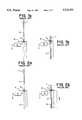
- the double-action antennacomprises, according to FIGS. 1a and 1b, two conducting antenna elements which are placed sequentially in an elongated antenna structure without a mutual, electrically transmitted connection.
- the top of the antennacomprises a conductor which is wound into a cylindrical coil, i.e., the so-called helix part 1, which, in the longitudinal direction of the antenna, is essentially shorter than a straight conductor, so-called rod part 2 which functions as the arm of the antenna.
- the transceiver unit of the telephoneis coupled to its lower end through sliding coupling 3 and it uses only the rod part as an antenna.
- One antenna solutionwhich has been used in portable radio sets for a long time, is a telescopic antenna which comprises nested, cylindrical elements which slide with respect to one another.
- the telescopic structureis expensive and relatively difficult to manufacture and it does not tolerate mechanical stress very well, therefore, it has not been particularly successful in mobile phones.
- Patent publication WO 92/16980presents a double-action antenna solution according to FIGS. 2a and 2b, comprising, in a similar manner as in the antenna presented in publication U.S. Pat. No, 5,204,687, sequential helix 1 and rod 2 parts which, in this case, are interconnected by using an electrically conductive connection.
- the idea of the inventionis to dimension the rod part 2 and its push-in case 5 so that in the passive position (FIG. 2b) the rod part is seen toward the helix part as a very high impedance and does not effect the operation of the helix part as an antenna. An incorrectly dimensioned rod part would cause undesired reflections or unnecessary attenuation on signals when pushed inside.
- rod part 2is preferably dimensioned into a length of half a wavelength.
- Half of the wavelengthis about 30 cm on a frequency of 450 MHz and about 15 cm on a frequency of 900 MHz, therefore, the rod part of half a wavelength according to publication WO 92/16980 is still fairly long for modern mobile phones. It is obvious that even shorter solutions in antenna structures should be reached.
- the problem with the above-described double-action antenna structuresis that if the antenna is not in either one of the extreme positions, no radiating element is coupled to the antenna port of the transceiver circuit of the radio set. If this is not taken into account when designing the antenna structure, the antenna port is seen as an open terminal in the transceiver circuit direction, whereby a major part of the transmitter power is reflected back to the transceiver circuit from the antenna port.
- mobile antenna element 2must also be provided with a length of half a wavelength to ensure sufficient electric performance, which was stated above as being impractical with respect to modern mobile phones.
- the object of the inventionis to provide an antenna structure which operates when retracted, when partly pulled out, and when completely pulled out, in a manner required by a data transmission system, preferably a mobile phone system, and which is very small in size.
- the structureshould be simple to manufacture and should, with respect to manufacturing costs, be well-adapted to mass production of mobile stations.
- the objectis achieved by using an antenna arrangement comprising a first antenna part, preferably a helix part, and a second antenna part, preferably a rod part, of which the first antenna part is fixed to the antenna port of a radio set and the second antenna part moves, with respect to the first antenna part, between two extreme positions, forming a serial connection with the first part in one of the positions.
- the antenna structure according to the inventionis characterized in that in relation to the first antenna part, the second antenna part can be moved into a position where it is coupled to the first antenna part at a point between the first and second ends of the first antenna part, forming a series connection, which couples to the antenna port of the radio set, with at least that portion of the first antenna part which is between the said point and the said first end.
- the inventionis based on the idea of coupling, in the active position, the second part of the antenna as an extension of the first part, whereby they form a series connection.
- the first partis preferably a conductor wound into a cylindrical coil, i.e., a helix antenna
- the second partis preferably a straight conductor, i.e., a rod antenna.
- When connected in seriesthey form a rod antenna shortened by an inductance (coil) which, in the direction of the longitudinal axis of the antenna structure, is shorter than the straight rod antenna of a corresponding electrical length.
- the helix antenna or a part thereof, which is connected between the antenna port and the rod antennacan be called a shortening coil in such an arrangement.
- FIG. 1apresents the double-action antenna structure known from U.S. Pat. No. 5,204,687 with the antenna pulled out,
- FIG. 1bpresents the double-action antenna structure known from U.S. Pat. No. 5,204,687 with the antenna retracted
- FIG. 2apresents the double-action antenna structure known from patent publication WO 92/16980 with the antenna pulled out
- FIG. 2bpresents the double-action antenna structure known from patent publication WO 92/16980 with the antenna retracted
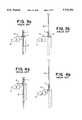
- FIG. 3apresents the double-action antenna structure known from patent publication WO 94/10720 with the antenna retracted
- FIG. 3bpresents the double-action antenna structure known from patent publication WO 94/10720 with the antenna pulled out
- FIG. 4apresents the double-action antenna structure known from U.S. Pat. No. 4,868,576 with the antenna retracted
- FIG. 4bpresents the double-action antenna structure known from U.S. Pat. No. 4,868,576 with the antenna pulled out
- FIGS. 5a and 5bpresent one embodiment of the antenna structure according to the invention with the antenna retracted and with the antenna pulled out
- FIGS. 6a and 6bpresent a second embodiment of the antenna structure according to the invention with the antenna retracted and with the antenna pulled out
- FIGS. 7a and 7bpresent a third embodiment of the antenna structure according to the invention with the antenna retracted and with the antenna pulled out
- FIGS. 8a and 8bpresent a fourth embodiment of the antenna structure according to the invention with the antenna retracted and with the antenna pulled out
- FIGS. 9a and 9bpresent a fifth embodiment of the antenna structure according to the invention with the antenna retracted and with the antenna pulled out.
- FIGS. 5a, 5b-9a, 9bpresent the double-action antenna structure according to the invention, comprising a helix part 1 and a rod part 2.
- Helix part 1is galvanically connected to the antenna port of the transceiver part of the radio communication set, or to the antenna-impedance matching circuit (not shown in the figures), through connecting part 12 made of conducting material, which also connects the antenna structure mechanically to the radio communication set (not shown in the figures).
- Enveloping helix part 1protective cover 13 made of elastic material is provided, protecting helix part 1 and the juncture between the helix part and connecting part 12.
- Both the connecting part 12 and the protective cover 13comprise, in the middle thereof, a hole in the direction of the symmetry axis of the structure, where the rod part 2 can be moved in the direction of the symmetry axis.
- the cylindrical coil conductor comprising helix part 1is wound in different ways at different points thereof.
- the lowest turnsare wound at a slight angle, whereby they form a thick supportive spiral 1d to provide a firm correction between helix part 1 and connecting part 12. Since the galvanic contact between connecting part 12 and supportive spiral 1d short circuits these turns, they do not belong to the actual radiating helix element which consists of three parts 1a, 1b, and 1c in the embodiment of FIGS. 5 and 6.
- the lowest part 1ais wound at a fairly loose ascending angle.
- part 1c of a smaller diameter and ascending anglecalled herein a coupling thread, through which helix part 1 is coupled to the pulled-out rod part 2.
- the diameter of the highest part 1bis as large as the lowest part 1a, but its ascending angle is more dense. The angle in the different parts of the helix part will be dealt with later on in this text.
- Rod part 2comprises radiating rod element 2a made of conducting material, and dielectric protective material 2b which covers it and is preferably made wider at the upper end thereof for a good grip.
- a bushing-like widening 2c made of conducting materialis provided at the lower end of rod element 2a, forming a galvanic contact between the lower end of rod element 2a and coupling thread 1c of the helix part when rod element 2 has been pulled out so far that said widening 2c touches coupling thread 1c.
- protective dielectric material 2b of the rod partis made wider at the lower end thereof so that rod part 2 cannot be pulled completely through coupling thread 1c.
- the coupling between the lower end of rod element 2a and coupling thread 1cis effected through an electromagnetic field.
- the rod part 2In the passive position, the rod part 2 has been pushed into its lower position, i.e., inside the outer shell (not shown in the figures) of the radio set, for the most part.
- Its protective cover 2b made of dielectric materialis preferably slightly longer at the upper end thereof than rod element 2a made of conducting material and placed inside of it, whereby conducting rod element 2a is completely pushed inside the radio set in the passive position and there is only dielectric material inside the radiating helix element 1a-1c.
- Thisis advantageous from the point of view of the operation of the antenna because a conducting material inside the radiating helix element, i.e., in the area between the highest and the lowest turns would have an adverse effect on the electric performance of the helix antenna.
- helix part 1Since helix part 1 is coupled to the antenna port (not shown in the figures) of the radio set through the supportive thread 1d and the connecting part 12, it functions as the antenna of the radio set in the passive position.
- a usercan pull the rod part 2 outside the outer shell (not shown) of the radio set for the most part, whereby conducting rod element 2a is coupled galvanically or through an electromagnetic field, at the lower end thereof, to coupling thread 1c of helix part 1 in the manner described above.
- the radiating antenna of the radio setconsists of the lowest part 1a of the helix element and of rod element 2a, which are connected in series.
- the arrangementcan be described by saying that rod element 2a replaces the uppermost part 1b of the helix element in the active position. This position, in which rod element 2a participates in the operation of the antenna by emitting RF-power, is called the active position as above.
- the dimensions of the helix part 1are specified so that, in the passive position, the electrical length of radiating helix element 1a-1c should be a fraction of the wavelength used, such as ⁇ /4, 3 ⁇ /8, or ⁇ /2.
- the length of rod element 2ais preferably one quarter of a wavelength.
- the antenna-impedance matching circuit(not shown in the figures) belonging to the radio set to function properly in both the active and the passive positions, the emitting antenna has to have the same electrical length in both positions. This requires that the part of helix element 1 that is replaced by rod element 2a in the active position (the uppermost part 1b in FIGS. 5 and 6), is electrically as long as rod element 2a. When rod element 2a replaces the uppermost part 1b of the helix element, the electrical length of the operating antenna remains the same.
- the parts 1a-1c of the helix element and the rod element 2aare dimensioned so that, in the active position, the electrical length of the antenna formed as the serial connection of the helix element and the rod element is greater than the electrical length of the mere radiating helix element 1a-1c in the passive position.
- Thisis carried out by lengthening the rod element and/or by forming said coupling thread 1c exactly at the upper part of helix part 1. If the length of rod element 2a is kept at ⁇ /4, helix element 1a-1c is provided with a length of ⁇ /4 or 3 ⁇ /8, and coupling thread 1c is formed at the upper part of the helix part, the electrical length of the antenna in the active position will be ⁇ /2 or 5 ⁇ /8, correspondingly.
- two impedance matching circuits(not shown in the figures) have to be made in the radio set for the active and passive positions, of which the right one is respectively selected by using, e.g., a separate switch (not shown in the figures).
- helix part 1is designed with a similar supportive spiral 1d provided at its lower part, as the one described above, but the actual radiating helix element 1e is a conical, helical conductor with a tapering diameter and a thickening angle of ascend.
- Conical widening 2eis provided at the lower end of rod part 2, which can be made entirely of conducting material, as in FIGS. 7a, 7b, or coated with a dielectric material as in FIGS. 8a, 8b.
- the shape and size of widening cone 2ecorrespond to the shape and size of the inner part of conical helix part 1e at the upper end thereof.
- the antenna structureis coupled to the antenna port (not shown in the figures) of the radio set through the supportive spiral 1d of the helix part and the connecting part 12 in a similar way as above.
- helix element 1eWhen rod part 2 is retracted, helix element 1e functions as the antenna of the radio set.
- the conical widening 2e at the lower end thereofis placed against the topmost turns of conical helix element 1e from the inside, short circuiting them either galvanically (FIGS. 7a, 7b) or through an electromagnetic field (FIGS. 8a, 8b).
- the serial connection formed by the non-short circuited turns 1f of the helix element 1e and by rod element 2afunction as the antenna of the radio set.
- the dimensions of the helix 1 and rod elements 2aadhere to the same principles that were described in connection with the above embodiments.
- the radio setonly comprises one antenna-impedance matching circuit (not shown in the figures), which should operate in an optimal way both in the active and in the passive positions, the total electrical length of helix element 1e has to be the same as the combined length of its non-short circuited turns 1f and the rod element 2a in the active position. If there are two matching circuits, the electrical length of the antenna can change between the active and the passive positions.
- FIGS. 9a and 9bpresent one embodiment of the invention in which the design of helix part 1 deviates from the embodiments described above.
- Supportive spiral part 1d and the coupling through it and the connecting part 12 to the antenna port(not shown in the figure) is similar to the one above, but the diameter of radiating helix element 1g is constant throughout the whole length thereof.
- An electrically conducting body 14is provided inside the helix element 1, dividing the helix element 1g into upper 1h and lower 1i parts and connecting the lower part 1i of the helix element and the rod element 2a in series in the active position, in the same way as coupling thread 1c presented in the embodiments of FIGS. 5a, 5b and 6a, 6b.
- rod element 2In the passive position, rod element 2 is again retracted and helix element 1g functions as the antenna of the radio set. In the active position, the coupler widening or coupling sleeve 2f of the lower end of rod part 2 is in contact with the said conducting body, whereby the series connection formed by the lower part 1i of the helix element and by, rod element 2a functions as the antenna.
- the same observationsarc true for the dimensions, which have been presented in connection with the previous embodiments.
- rod part 2has to replace, in the active position, a part of helix part 1 which is of the same size as its own electrical length.
- rod element ⁇ /4; helix element ⁇ /4, 3 ⁇ /8, or ⁇ /2it means that above the point where the lower end of rod part 2 is coupled to helix part 1 there has to be a part of the helix part whose electrical length is greater than, or at least as great as the part below it.
- This requirementis preferably met by winding the upper part of the helix part more closely, i.e., with a smaller ascending angle than in the lower part. If the desired distribution of the electrical length is achieved by making the helix more dense in this way, the diameter of the helix turn can increase, remain the same, or decrease towards the upper end of the helix part. If the ascending angle of the helix thread is kept constant throughout the entire length of the helix part, the requirement for the distribution of the electrical length can be met by increasing the diameter of the helix turn towards its upper end. Otherwise, the structure according to the invention can be used only to implement a double-action antenna which requires discrete antenna-impedance matching circuits for the active and the passive positions.
- the antenna structure according to the inventionis small in size and its electric performance is good. Some emitting element is continuously in connection with the antenna port of the radio set, whereby there is no danger of transmission signals reflecting back to the transceiver circuit. All the parts of the antenna structure are suitable for mass production, and no strict tolerance requirements need to be set for them, whereby manufacturing costs remain reasonaable.
- the above-presented embodimentsare intended to illustrate the technical implementation of the antenna structure according to the invention, and the invention is not limited to them, but it is possible, for those skilled in the art, to also implement other embodiments on the basis of the characterizing features presented in the claims.
- the present inventionis not restricted to any particular application but can be used in antennas in different applications and on different frequencies, preferably on radio frequencies, such as the UHF and the VHF.
- the structureis preferably used in mobile phone antennas.
Landscapes
- Engineering & Computer Science (AREA)
- Computer Networks & Wireless Communication (AREA)
- Details Of Aerials (AREA)
- Support Of Aerials (AREA)
Abstract
Description
Claims (12)
Applications Claiming Priority (2)
| Application Number | Priority Date | Filing Date | Title |
|---|---|---|---|
| FI952742AFI98165C (en) | 1995-06-05 | 1995-06-05 | Dual function antenna |
| FI952742 | 1995-06-05 |
Publications (1)
| Publication Number | Publication Date |
|---|---|
| US5734351Atrue US5734351A (en) | 1998-03-31 |
Family
ID=8543537
Family Applications (1)
| Application Number | Title | Priority Date | Filing Date |
|---|---|---|---|
| US08/654,687Expired - LifetimeUS5734351A (en) | 1995-06-05 | 1996-05-29 | Double-action antenna |
Country Status (7)
| Country | Link |
|---|---|
| US (1) | US5734351A (en) |
| EP (1) | EP0747989B1 (en) |
| JP (1) | JPH08330829A (en) |
| AU (1) | AU707407B2 (en) |
| CA (1) | CA2175274A1 (en) |
| DE (1) | DE69623184T2 (en) |
| FI (1) | FI98165C (en) |
Cited By (45)
| Publication number | Priority date | Publication date | Assignee | Title |
|---|---|---|---|---|
| US6016130A (en)* | 1996-08-22 | 2000-01-18 | Lk-Products Oy | Dual-frequency antenna |
| US6052089A (en)* | 1997-12-23 | 2000-04-18 | Nokia Mobile Phones Limited | Half-wave retractable antenna with matching helix |
| US6057807A (en)* | 1996-02-13 | 2000-05-02 | Allgon Ab | Dual band antenna means incorporating helical and elongated radiating structures |
| US6087994A (en)* | 1999-01-19 | 2000-07-11 | Lechter; Robert | Retractable antenna for a cellular phone |
| US6198443B1 (en) | 1999-07-30 | 2001-03-06 | Centurion Intl., Inc. | Dual band antenna for cellular communications |
| US6212400B1 (en)* | 1997-04-15 | 2001-04-03 | Siemens Aktiengesellschaft | Antenna device for mobile radio telephone devices |
| US6232929B1 (en) | 1997-11-27 | 2001-05-15 | Nokia Mobile Phones Ltd. | Multi-filar helix antennae |
| US6232925B1 (en)* | 1994-01-28 | 2001-05-15 | Smk Corporation | Antenna device |
| US6359598B1 (en)* | 1999-05-03 | 2002-03-19 | Centurion Wireless Technologies, Inc. | Plastic or die-cast antenna for a wireless communications device |
| US20020135533A1 (en)* | 2001-03-24 | 2002-09-26 | Samsung Electronics Co., Ltd. | Retractable/extendable antenna unit having a conductive tube in a portable radiophone |
| US7663551B2 (en) | 2005-11-24 | 2010-02-16 | Pulse Finald Oy | Multiband antenna apparatus and methods |
| US20100220016A1 (en)* | 2005-10-03 | 2010-09-02 | Pertti Nissinen | Multiband Antenna System And Methods |
| US20100244978A1 (en)* | 2007-04-19 | 2010-09-30 | Zlatoljub Milosavljevic | Methods and apparatus for matching an antenna |
| US20100295737A1 (en)* | 2005-07-25 | 2010-11-25 | Zlatoljub Milosavljevic | Adjustable Multiband Antenna and Methods |
| US20110156972A1 (en)* | 2009-12-29 | 2011-06-30 | Heikki Korva | Loop resonator apparatus and methods for enhanced field control |
| US8390522B2 (en) | 2004-06-28 | 2013-03-05 | Pulse Finland Oy | Antenna, component and methods |
| US8473017B2 (en) | 2005-10-14 | 2013-06-25 | Pulse Finland Oy | Adjustable antenna and methods |
| US8618990B2 (en) | 2011-04-13 | 2013-12-31 | Pulse Finland Oy | Wideband antenna and methods |
| US8629813B2 (en) | 2007-08-30 | 2014-01-14 | Pusle Finland Oy | Adjustable multi-band antenna and methods |
| US8648752B2 (en) | 2011-02-11 | 2014-02-11 | Pulse Finland Oy | Chassis-excited antenna apparatus and methods |
| US8866689B2 (en) | 2011-07-07 | 2014-10-21 | Pulse Finland Oy | Multi-band antenna and methods for long term evolution wireless system |
| US8988296B2 (en) | 2012-04-04 | 2015-03-24 | Pulse Finland Oy | Compact polarized antenna and methods |
| US9123990B2 (en) | 2011-10-07 | 2015-09-01 | Pulse Finland Oy | Multi-feed antenna apparatus and methods |
| US9203154B2 (en) | 2011-01-25 | 2015-12-01 | Pulse Finland Oy | Multi-resonance antenna, antenna module, radio device and methods |
| US9246210B2 (en) | 2010-02-18 | 2016-01-26 | Pulse Finland Oy | Antenna with cover radiator and methods |
| US9350081B2 (en) | 2014-01-14 | 2016-05-24 | Pulse Finland Oy | Switchable multi-radiator high band antenna apparatus |
| US9406998B2 (en) | 2010-04-21 | 2016-08-02 | Pulse Finland Oy | Distributed multiband antenna and methods |
| US9450291B2 (en) | 2011-07-25 | 2016-09-20 | Pulse Finland Oy | Multiband slot loop antenna apparatus and methods |
| US9461371B2 (en) | 2009-11-27 | 2016-10-04 | Pulse Finland Oy | MIMO antenna and methods |
| US9484619B2 (en) | 2011-12-21 | 2016-11-01 | Pulse Finland Oy | Switchable diversity antenna apparatus and methods |
| US9531058B2 (en) | 2011-12-20 | 2016-12-27 | Pulse Finland Oy | Loosely-coupled radio antenna apparatus and methods |
| US9590308B2 (en) | 2013-12-03 | 2017-03-07 | Pulse Electronics, Inc. | Reduced surface area antenna apparatus and mobile communications devices incorporating the same |
| US9634383B2 (en) | 2013-06-26 | 2017-04-25 | Pulse Finland Oy | Galvanically separated non-interacting antenna sector apparatus and methods |
| US9647338B2 (en) | 2013-03-11 | 2017-05-09 | Pulse Finland Oy | Coupled antenna structure and methods |
| US9673507B2 (en) | 2011-02-11 | 2017-06-06 | Pulse Finland Oy | Chassis-excited antenna apparatus and methods |
| US9680212B2 (en) | 2013-11-20 | 2017-06-13 | Pulse Finland Oy | Capacitive grounding methods and apparatus for mobile devices |
| US9722308B2 (en) | 2014-08-28 | 2017-08-01 | Pulse Finland Oy | Low passive intermodulation distributed antenna system for multiple-input multiple-output systems and methods of use |
| US9761951B2 (en) | 2009-11-03 | 2017-09-12 | Pulse Finland Oy | Adjustable antenna apparatus and methods |
| US9906260B2 (en) | 2015-07-30 | 2018-02-27 | Pulse Finland Oy | Sensor-based closed loop antenna swapping apparatus and methods |
| US9948002B2 (en) | 2014-08-26 | 2018-04-17 | Pulse Finland Oy | Antenna apparatus with an integrated proximity sensor and methods |
| US9973228B2 (en) | 2014-08-26 | 2018-05-15 | Pulse Finland Oy | Antenna apparatus with an integrated proximity sensor and methods |
| US9979078B2 (en) | 2012-10-25 | 2018-05-22 | Pulse Finland Oy | Modular cell antenna apparatus and methods |
| US10069209B2 (en) | 2012-11-06 | 2018-09-04 | Pulse Finland Oy | Capacitively coupled antenna apparatus and methods |
| US10079428B2 (en) | 2013-03-11 | 2018-09-18 | Pulse Finland Oy | Coupled antenna structure and methods |
| US10211538B2 (en) | 2006-12-28 | 2019-02-19 | Pulse Finland Oy | Directional antenna apparatus and methods |
Families Citing this family (15)
| Publication number | Priority date | Publication date | Assignee | Title |
|---|---|---|---|---|
| JPH1032410A (en)* | 1996-07-12 | 1998-02-03 | Saitama Nippon Denki Kk | Antenna for portable radio equipment |
| US5963871A (en)* | 1996-10-04 | 1999-10-05 | Telefonaktiebolaget Lm Ericsson | Retractable multi-band antennas |
| US6310578B1 (en)* | 1997-10-28 | 2001-10-30 | Telefonaktiebolaget Lm Ericsson (Publ) | Multiple band telescope type antenna for mobile phone |
| US6329962B2 (en) | 1998-08-04 | 2001-12-11 | Telefonaktiebolaget Lm Ericsson (Publ) | Multiple band, multiple branch antenna for mobile phone |
| FI111884B (en)* | 1997-12-16 | 2003-09-30 | Filtronic Lk Oy | Helix antenna for dual frequency operation |
| KR100304354B1 (en)* | 1998-06-11 | 2001-09-24 | 구관영 | Dual Band Retractable Antenna and Matching Circuitry by Capacitive Coupling Method |
| JPH11355029A (en)* | 1998-06-12 | 1999-12-24 | Smk Corp | Antenna device |
| US6166694A (en)* | 1998-07-09 | 2000-12-26 | Telefonaktiebolaget Lm Ericsson (Publ) | Printed twin spiral dual band antenna |
| US6353443B1 (en) | 1998-07-09 | 2002-03-05 | Telefonaktiebolaget Lm Ericsson (Publ) | Miniature printed spiral antenna for mobile terminals |
| US6343208B1 (en) | 1998-12-16 | 2002-01-29 | Telefonaktiebolaget Lm Ericsson (Publ) | Printed multi-band patch antenna |
| FR2794574A1 (en)* | 1999-06-02 | 2000-12-08 | Socapex Amphenol | Retractable dual band antenna for mobile phones has moveable whip and two helical antennas with different winding pitches |
| WO2001035488A1 (en)* | 1999-11-10 | 2001-05-17 | Avantego Ab | Antenna arrangement |
| JP2002359514A (en)* | 2001-05-31 | 2002-12-13 | Anten Corp | Helical antenna |
| JP4037703B2 (en) | 2002-06-28 | 2008-01-23 | 日本電気株式会社 | Built-in antenna and radio |
| JP6594210B2 (en)* | 2016-01-08 | 2019-10-23 | アルパイン株式会社 | Radio communication antenna and radio communication module |
Citations (12)
| Publication number | Priority date | Publication date | Assignee | Title |
|---|---|---|---|---|
| DE2253949A1 (en)* | 1971-12-29 | 1973-07-05 | Huffman Manufacturing Co | METHOD AND DEVICE FOR ASSEMBLING A WHEEL WITH A RIM, HUB AND MULTIPLE SPOKES |
| US4868576A (en)* | 1988-11-02 | 1989-09-19 | Motorola, Inc. | Extendable antenna for portable cellular telephones with ground radiator |
| EP0511577A2 (en)* | 1991-04-30 | 1992-11-04 | Siemens Aktiengesellschaft | Compact, in particular portable radio transceiver with retractable or collapsible antenna |
| WO1994010720A1 (en)* | 1992-10-29 | 1994-05-11 | Allgon Ab | An antenna device for portable equipment |
| EP0644606A1 (en)* | 1993-09-16 | 1995-03-22 | Fujitsu Limited | Portable radio communication device and loaded antenna therefor |
| WO1995008853A1 (en)* | 1993-09-20 | 1995-03-30 | Motorola, Inc. | Antenna arrangement for a wireless communication device |
| EP0650215A2 (en)* | 1993-09-29 | 1995-04-26 | Ntt Mobile Communications Network Inc. | Antenna equipment |
| WO1995012224A1 (en)* | 1993-10-29 | 1995-05-04 | Allgon Ab | Broadband aerial means |
| GB2284101A (en)* | 1993-11-17 | 1995-05-24 | Antenna Products Ltd | Coupling arrangement for radio frequency signals |
| EP0660440A1 (en)* | 1993-12-22 | 1995-06-28 | Nokia Mobile Phones Ltd. | Retractable antenna |
| US5446469A (en)* | 1993-01-14 | 1995-08-29 | Nippon Antenna Co., Ltd. | Extendible whip antenna |
| WO1996000990A1 (en)* | 1994-06-28 | 1996-01-11 | Sony Corporation | Antenna device and portable radio device |
Family Cites Families (1)
| Publication number | Priority date | Publication date | Assignee | Title |
|---|---|---|---|---|
| GB2253949B (en)* | 1991-03-16 | 1995-08-09 | Antenna Products Ltd | Radio Antennas |
- 1995
- 1995-06-05FIFI952742Apatent/FI98165C/enactive
- 1996
- 1996-04-09AUAU50551/96Apatent/AU707407B2/ennot_activeCeased
- 1996-04-29CACA002175274Apatent/CA2175274A1/ennot_activeAbandoned
- 1996-05-29USUS08/654,687patent/US5734351A/ennot_activeExpired - Lifetime
- 1996-06-05EPEP96304136Apatent/EP0747989B1/ennot_activeExpired - Lifetime
- 1996-06-05JPJP8163651Apatent/JPH08330829A/enactivePending
- 1996-06-05DEDE69623184Tpatent/DE69623184T2/ennot_activeExpired - Fee Related
Patent Citations (13)
| Publication number | Priority date | Publication date | Assignee | Title |
|---|---|---|---|---|
| DE2253949A1 (en)* | 1971-12-29 | 1973-07-05 | Huffman Manufacturing Co | METHOD AND DEVICE FOR ASSEMBLING A WHEEL WITH A RIM, HUB AND MULTIPLE SPOKES |
| US4868576A (en)* | 1988-11-02 | 1989-09-19 | Motorola, Inc. | Extendable antenna for portable cellular telephones with ground radiator |
| EP0511577A2 (en)* | 1991-04-30 | 1992-11-04 | Siemens Aktiengesellschaft | Compact, in particular portable radio transceiver with retractable or collapsible antenna |
| WO1994010720A1 (en)* | 1992-10-29 | 1994-05-11 | Allgon Ab | An antenna device for portable equipment |
| US5446469A (en)* | 1993-01-14 | 1995-08-29 | Nippon Antenna Co., Ltd. | Extendible whip antenna |
| EP0644606A1 (en)* | 1993-09-16 | 1995-03-22 | Fujitsu Limited | Portable radio communication device and loaded antenna therefor |
| FI952406A7 (en)* | 1993-09-20 | 1995-05-17 | Motorola Inc | Antenna arrangement for a wireless communication device |
| WO1995008853A1 (en)* | 1993-09-20 | 1995-03-30 | Motorola, Inc. | Antenna arrangement for a wireless communication device |
| EP0650215A2 (en)* | 1993-09-29 | 1995-04-26 | Ntt Mobile Communications Network Inc. | Antenna equipment |
| WO1995012224A1 (en)* | 1993-10-29 | 1995-05-04 | Allgon Ab | Broadband aerial means |
| GB2284101A (en)* | 1993-11-17 | 1995-05-24 | Antenna Products Ltd | Coupling arrangement for radio frequency signals |
| EP0660440A1 (en)* | 1993-12-22 | 1995-06-28 | Nokia Mobile Phones Ltd. | Retractable antenna |
| WO1996000990A1 (en)* | 1994-06-28 | 1996-01-11 | Sony Corporation | Antenna device and portable radio device |
Cited By (54)
| Publication number | Priority date | Publication date | Assignee | Title |
|---|---|---|---|---|
| US6232925B1 (en)* | 1994-01-28 | 2001-05-15 | Smk Corporation | Antenna device |
| US6057807A (en)* | 1996-02-13 | 2000-05-02 | Allgon Ab | Dual band antenna means incorporating helical and elongated radiating structures |
| US6016130A (en)* | 1996-08-22 | 2000-01-18 | Lk-Products Oy | Dual-frequency antenna |
| US6212400B1 (en)* | 1997-04-15 | 2001-04-03 | Siemens Aktiengesellschaft | Antenna device for mobile radio telephone devices |
| US6232929B1 (en) | 1997-11-27 | 2001-05-15 | Nokia Mobile Phones Ltd. | Multi-filar helix antennae |
| US6052089A (en)* | 1997-12-23 | 2000-04-18 | Nokia Mobile Phones Limited | Half-wave retractable antenna with matching helix |
| US6087994A (en)* | 1999-01-19 | 2000-07-11 | Lechter; Robert | Retractable antenna for a cellular phone |
| US6492960B2 (en) | 1999-05-03 | 2002-12-10 | Centurion Wireless Technologies, Inc. | Plastic or die-cast antennas for a wireless communications device |
| US6359598B1 (en)* | 1999-05-03 | 2002-03-19 | Centurion Wireless Technologies, Inc. | Plastic or die-cast antenna for a wireless communications device |
| US6198443B1 (en) | 1999-07-30 | 2001-03-06 | Centurion Intl., Inc. | Dual band antenna for cellular communications |
| US6249257B1 (en) | 1999-07-30 | 2001-06-19 | Centurion Wireless Technologies, Inc. | Switched, dual helical, retractable, dual band antenna for cellular communications |
| US6756943B2 (en)* | 2001-03-24 | 2004-06-29 | Samsung Electronics Co., Ltd. | Retractable/extendable antenna unit having a conductive tube in a portable radiophone |
| US20020135533A1 (en)* | 2001-03-24 | 2002-09-26 | Samsung Electronics Co., Ltd. | Retractable/extendable antenna unit having a conductive tube in a portable radiophone |
| US8390522B2 (en) | 2004-06-28 | 2013-03-05 | Pulse Finland Oy | Antenna, component and methods |
| US8564485B2 (en) | 2005-07-25 | 2013-10-22 | Pulse Finland Oy | Adjustable multiband antenna and methods |
| US20100295737A1 (en)* | 2005-07-25 | 2010-11-25 | Zlatoljub Milosavljevic | Adjustable Multiband Antenna and Methods |
| US20100220016A1 (en)* | 2005-10-03 | 2010-09-02 | Pertti Nissinen | Multiband Antenna System And Methods |
| US8786499B2 (en) | 2005-10-03 | 2014-07-22 | Pulse Finland Oy | Multiband antenna system and methods |
| US8473017B2 (en) | 2005-10-14 | 2013-06-25 | Pulse Finland Oy | Adjustable antenna and methods |
| US7663551B2 (en) | 2005-11-24 | 2010-02-16 | Pulse Finald Oy | Multiband antenna apparatus and methods |
| US10211538B2 (en) | 2006-12-28 | 2019-02-19 | Pulse Finland Oy | Directional antenna apparatus and methods |
| US20100244978A1 (en)* | 2007-04-19 | 2010-09-30 | Zlatoljub Milosavljevic | Methods and apparatus for matching an antenna |
| US8466756B2 (en) | 2007-04-19 | 2013-06-18 | Pulse Finland Oy | Methods and apparatus for matching an antenna |
| US8629813B2 (en) | 2007-08-30 | 2014-01-14 | Pusle Finland Oy | Adjustable multi-band antenna and methods |
| US9761951B2 (en) | 2009-11-03 | 2017-09-12 | Pulse Finland Oy | Adjustable antenna apparatus and methods |
| US9461371B2 (en) | 2009-11-27 | 2016-10-04 | Pulse Finland Oy | MIMO antenna and methods |
| US8847833B2 (en) | 2009-12-29 | 2014-09-30 | Pulse Finland Oy | Loop resonator apparatus and methods for enhanced field control |
| US20110156972A1 (en)* | 2009-12-29 | 2011-06-30 | Heikki Korva | Loop resonator apparatus and methods for enhanced field control |
| US9246210B2 (en) | 2010-02-18 | 2016-01-26 | Pulse Finland Oy | Antenna with cover radiator and methods |
| US9406998B2 (en) | 2010-04-21 | 2016-08-02 | Pulse Finland Oy | Distributed multiband antenna and methods |
| US9203154B2 (en) | 2011-01-25 | 2015-12-01 | Pulse Finland Oy | Multi-resonance antenna, antenna module, radio device and methods |
| US8648752B2 (en) | 2011-02-11 | 2014-02-11 | Pulse Finland Oy | Chassis-excited antenna apparatus and methods |
| US9917346B2 (en) | 2011-02-11 | 2018-03-13 | Pulse Finland Oy | Chassis-excited antenna apparatus and methods |
| US9673507B2 (en) | 2011-02-11 | 2017-06-06 | Pulse Finland Oy | Chassis-excited antenna apparatus and methods |
| US8618990B2 (en) | 2011-04-13 | 2013-12-31 | Pulse Finland Oy | Wideband antenna and methods |
| US8866689B2 (en) | 2011-07-07 | 2014-10-21 | Pulse Finland Oy | Multi-band antenna and methods for long term evolution wireless system |
| US9450291B2 (en) | 2011-07-25 | 2016-09-20 | Pulse Finland Oy | Multiband slot loop antenna apparatus and methods |
| US9123990B2 (en) | 2011-10-07 | 2015-09-01 | Pulse Finland Oy | Multi-feed antenna apparatus and methods |
| US9531058B2 (en) | 2011-12-20 | 2016-12-27 | Pulse Finland Oy | Loosely-coupled radio antenna apparatus and methods |
| US9484619B2 (en) | 2011-12-21 | 2016-11-01 | Pulse Finland Oy | Switchable diversity antenna apparatus and methods |
| US9509054B2 (en) | 2012-04-04 | 2016-11-29 | Pulse Finland Oy | Compact polarized antenna and methods |
| US8988296B2 (en) | 2012-04-04 | 2015-03-24 | Pulse Finland Oy | Compact polarized antenna and methods |
| US9979078B2 (en) | 2012-10-25 | 2018-05-22 | Pulse Finland Oy | Modular cell antenna apparatus and methods |
| US10069209B2 (en) | 2012-11-06 | 2018-09-04 | Pulse Finland Oy | Capacitively coupled antenna apparatus and methods |
| US9647338B2 (en) | 2013-03-11 | 2017-05-09 | Pulse Finland Oy | Coupled antenna structure and methods |
| US10079428B2 (en) | 2013-03-11 | 2018-09-18 | Pulse Finland Oy | Coupled antenna structure and methods |
| US9634383B2 (en) | 2013-06-26 | 2017-04-25 | Pulse Finland Oy | Galvanically separated non-interacting antenna sector apparatus and methods |
| US9680212B2 (en) | 2013-11-20 | 2017-06-13 | Pulse Finland Oy | Capacitive grounding methods and apparatus for mobile devices |
| US9590308B2 (en) | 2013-12-03 | 2017-03-07 | Pulse Electronics, Inc. | Reduced surface area antenna apparatus and mobile communications devices incorporating the same |
| US9350081B2 (en) | 2014-01-14 | 2016-05-24 | Pulse Finland Oy | Switchable multi-radiator high band antenna apparatus |
| US9948002B2 (en) | 2014-08-26 | 2018-04-17 | Pulse Finland Oy | Antenna apparatus with an integrated proximity sensor and methods |
| US9973228B2 (en) | 2014-08-26 | 2018-05-15 | Pulse Finland Oy | Antenna apparatus with an integrated proximity sensor and methods |
| US9722308B2 (en) | 2014-08-28 | 2017-08-01 | Pulse Finland Oy | Low passive intermodulation distributed antenna system for multiple-input multiple-output systems and methods of use |
| US9906260B2 (en) | 2015-07-30 | 2018-02-27 | Pulse Finland Oy | Sensor-based closed loop antenna swapping apparatus and methods |
Also Published As
| Publication number | Publication date |
|---|---|
| FI98165B (en) | 1997-01-15 |
| DE69623184T2 (en) | 2003-05-28 |
| AU707407B2 (en) | 1999-07-08 |
| FI952742A0 (en) | 1995-06-05 |
| EP0747989B1 (en) | 2002-08-28 |
| EP0747989A1 (en) | 1996-12-11 |
| DE69623184D1 (en) | 2002-10-02 |
| AU5055196A (en) | 1996-12-19 |
| CA2175274A1 (en) | 1996-12-06 |
| JPH08330829A (en) | 1996-12-13 |
| FI98165C (en) | 1997-04-25 |
Similar Documents
| Publication | Publication Date | Title |
|---|---|---|
| US5734351A (en) | Double-action antenna | |
| US6054966A (en) | Antenna operating in two frequency ranges | |
| KR100384656B1 (en) | Dual-band helix antenna with parasitic element | |
| US6069592A (en) | Meander antenna device | |
| KR20020044585A (en) | Balanced, retractable mobile phone antenna | |
| WO1995008853A1 (en) | Antenna arrangement for a wireless communication device | |
| JP2001053518A (en) | Antenna device and portable wireless device | |
| US6064346A (en) | Antenna assembly | |
| KR20000026803A (en) | Extension antenna apparatus using metal tube | |
| US6269240B1 (en) | Slidable connection for a retractable antenna to a mobile radio | |
| EP0736925B1 (en) | A double-acting antenna and a mobile phone comprising such an antenna | |
| KR100619191B1 (en) | Insertion Antenna with Minimal Frequency Variation | |
| US6336036B1 (en) | Retractable dual-band tapped helical radiotelephone antennas | |
| ES2260461T3 (en) | HELICOIDAL ANTENNA. | |
| KR20020016934A (en) | Dual band antenna device | |
| JP2001053520A (en) | Antenna system and portable radio device | |
| KR20000077131A (en) | Retractable multiband radiator with switching contact for wireless communication devices | |
| WO1999054959A1 (en) | Antenna means and a handheld radio communication device including such means | |
| JP2001053522A (en) | Antenna system and portable radio device | |
| WO2001035488A1 (en) | Antenna arrangement | |
| WO2001011717A1 (en) | Antenna arrangement | |
| KR20000016682A (en) | Meander antenna device | |
| JPH10270918A (en) | Antenna for portable radio equipment | |
| JP2001053523A (en) | Antenna system and portable radio equipment |
Legal Events
| Date | Code | Title | Description |
|---|---|---|---|
| AS | Assignment | Owner name:LK-PRODUCTS OY, FINLAND Free format text:ASSIGNMENT OF ASSIGNORS INTEREST;ASSIGNORS:OJANTAKANEN, SEPPO;RAATIKAINEN, SEPPO;ANNAMAA, PETTERI;AND OTHERS;REEL/FRAME:008172/0420 Effective date:19950321 | |
| STCF | Information on status: patent grant | Free format text:PATENTED CASE | |
| AS | Assignment | Owner name:FILTRONIC LK OY, FINLAND Free format text:CHANGE OF NAME;ASSIGNOR:LK-PRODUCTS OY;REEL/FRAME:011682/0801 Effective date:20000518 | |
| FPAY | Fee payment | Year of fee payment:4 | |
| AS | Assignment | Owner name:LK PRODUCTS OY, FINLAND Free format text:ASSIGNMENT OF ASSIGNORS INTEREST;ASSIGNOR:FILTRONIC LK OY;REEL/FRAME:016662/0450 Effective date:20050808 | |
| FPAY | Fee payment | Year of fee payment:8 | |
| AS | Assignment | Owner name:PULSE FINLAND OY, FINLAND Free format text:CHANGE OF NAME;ASSIGNOR:LK PRODUCTS OY;REEL/FRAME:018420/0713 Effective date:20060901 | |
| FPAY | Fee payment | Year of fee payment:12 | |
| AS | Assignment | Owner name:CANTOR FITZGERALD SECURITIES, NEW YORK Free format text:NOTICE OF SUBSTITUTION OF ADMINISTRATIVE AGENT IN TRADEMARKS AND PATENTS;ASSIGNOR:JPMORGAN CHASE BANK, N.A.;REEL/FRAME:031898/0476 Effective date:20131030 |