US5733323A - Electrically conductive unipolar vascular sheath - Google Patents
Electrically conductive unipolar vascular sheathDownload PDFInfo
- Publication number
- US5733323A US5733323AUS08/558,641US55864195AUS5733323AUS 5733323 AUS5733323 AUS 5733323AUS 55864195 AUS55864195 AUS 55864195AUS 5733323 AUS5733323 AUS 5733323A
- Authority
- US
- United States
- Prior art keywords
- electrically conductive
- elongated
- sheath introducer
- accordance
- generally cylindrical
- Prior art date
- Legal status (The legal status is an assumption and is not a legal conclusion. Google has not performed a legal analysis and makes no representation as to the accuracy of the status listed.)
- Expired - Lifetime
Links
- 230000002792vascularEffects0.000titleclaimsabstractdescription19
- 239000007769metal materialSubstances0.000claimsabstractdescription47
- 239000000463materialSubstances0.000claimsabstractdescription18
- 239000004020conductorSubstances0.000claimsdescription21
- 230000001464adherent effectEffects0.000claimsdescription14
- BASFCYQUMIYNBI-UHFFFAOYSA-NplatinumChemical compound[Pt]BASFCYQUMIYNBI-UHFFFAOYSA-N0.000claimsdescription10
- BQCADISMDOOEFD-UHFFFAOYSA-NSilverChemical compound[Ag]BQCADISMDOOEFD-UHFFFAOYSA-N0.000claimsdescription9
- PCHJSUWPFVWCPO-UHFFFAOYSA-NgoldChemical compound[Au]PCHJSUWPFVWCPO-UHFFFAOYSA-N0.000claimsdescription8
- 229910052737goldInorganic materials0.000claimsdescription8
- 239000010931goldSubstances0.000claimsdescription8
- 229910052709silverInorganic materials0.000claimsdescription8
- 239000004332silverSubstances0.000claimsdescription8
- RTAQQCXQSZGOHL-UHFFFAOYSA-NTitaniumChemical compound[Ti]RTAQQCXQSZGOHL-UHFFFAOYSA-N0.000claimsdescription7
- 229910052719titaniumInorganic materials0.000claimsdescription7
- 239000010936titaniumSubstances0.000claimsdescription7
- 229910052697platinumInorganic materials0.000claimsdescription5
- 229910052715tantalumInorganic materials0.000claimsdescription5
- GUVRBAGPIYLISA-UHFFFAOYSA-Ntantalum atomChemical compound[Ta]GUVRBAGPIYLISA-UHFFFAOYSA-N0.000claimsdescription5
- 238000010884ion-beam techniqueMethods0.000claimsdescription4
- 238000005229chemical vapour depositionMethods0.000claimsdescription2
- 238000000034methodMethods0.000abstractdescription25
- 230000008021depositionEffects0.000abstractdescription10
- 239000011248coating agentSubstances0.000description11
- 238000000576coating methodMethods0.000description11
- 238000000151depositionMethods0.000description9
- 239000004952PolyamideSubstances0.000description6
- 229920002647polyamidePolymers0.000description6
- 238000004891communicationMethods0.000description5
- 239000010408filmSubstances0.000description5
- 239000010935stainless steelSubstances0.000description5
- 229910001220stainless steelInorganic materials0.000description5
- RTZKZFJDLAIYFH-UHFFFAOYSA-NDiethyl etherChemical compoundCCOCCRTZKZFJDLAIYFH-UHFFFAOYSA-N0.000description4
- 238000002679ablationMethods0.000description4
- 229910052751metalInorganic materials0.000description4
- 229910000792MonelInorganic materials0.000description3
- 238000013507mappingMethods0.000description3
- 239000002184metalSubstances0.000description3
- 229910001092metal group alloyInorganic materials0.000description3
- 229920002614Polyether block amidePolymers0.000description2
- 229910000831SteelInorganic materials0.000description2
- NRTOMJZYCJJWKI-UHFFFAOYSA-NTitanium nitrideChemical compound[Ti]#NNRTOMJZYCJJWKI-UHFFFAOYSA-N0.000description2
- 229920001971elastomerPolymers0.000description2
- 239000000806elastomerSubstances0.000description2
- 235000019589hardnessNutrition0.000description2
- 150000002736metal compoundsChemical class0.000description2
- 229920001778nylonPolymers0.000description2
- 230000002093peripheral effectEffects0.000description2
- 239000010959steelSubstances0.000description2
- 239000010409thin filmSubstances0.000description2
- 229910000851Alloy steelInorganic materials0.000description1
- 239000004677NylonSubstances0.000description1
- 239000004698PolyethyleneSubstances0.000description1
- 239000004809TeflonSubstances0.000description1
- 229920006362Teflon®Polymers0.000description1
- 210000001015abdomenAnatomy0.000description1
- 229910045601alloyInorganic materials0.000description1
- 239000000956alloySubstances0.000description1
- 238000013459approachMethods0.000description1
- 238000007630basic procedureMethods0.000description1
- 229920001400block copolymerPolymers0.000description1
- 210000004204blood vesselAnatomy0.000description1
- 230000036760body temperatureEffects0.000description1
- 210000000038chestAnatomy0.000description1
- 230000015271coagulationEffects0.000description1
- 238000005345coagulationMethods0.000description1
- 150000001875compoundsChemical class0.000description1
- 230000007423decreaseEffects0.000description1
- 230000032798delaminationEffects0.000description1
- 239000012530fluidSubstances0.000description1
- 238000011010flushing procedureMethods0.000description1
- 210000004013groinAnatomy0.000description1
- 238000010438heat treatmentMethods0.000description1
- 229920001519homopolymerPolymers0.000description1
- 238000001727in vivoMethods0.000description1
- 230000002452interceptive effectEffects0.000description1
- 238000012986modificationMethods0.000description1
- 230000004048modificationEffects0.000description1
- 210000000056organAnatomy0.000description1
- 229920000728polyesterPolymers0.000description1
- 229920000573polyethylenePolymers0.000description1
- -1polyethylenesPolymers0.000description1
- 229920000642polymerPolymers0.000description1
- 229920002635polyurethanePolymers0.000description1
- 239000004814polyurethaneSubstances0.000description1
- 238000002360preparation methodMethods0.000description1
- 238000012545processingMethods0.000description1
- 238000006748scratchingMethods0.000description1
- 230000002393scratching effectEffects0.000description1
- 239000000126substanceSubstances0.000description1
- 238000001356surgical procedureMethods0.000description1
- 235000019587textureNutrition0.000description1
Images

Classifications
- A—HUMAN NECESSITIES
- A61—MEDICAL OR VETERINARY SCIENCE; HYGIENE
- A61N—ELECTROTHERAPY; MAGNETOTHERAPY; RADIATION THERAPY; ULTRASOUND THERAPY
- A61N1/00—Electrotherapy; Circuits therefor
- A61N1/02—Details
- A61N1/04—Electrodes
- A61N1/05—Electrodes for implantation or insertion into the body, e.g. heart electrode
- A61N1/056—Transvascular endocardial electrode systems
Definitions
- the present inventiongenerally relates to an electrically conductive percutaneous unipolar vascular sheath introducer having especially advantageous electrical properties. More particularly, the unipolar vascular sheath includes a conductive cannula shaft made of a polymeric material having an outer surface which is an adherent thin metallic material film that is of very low resistivity and that is chemically and/or mechanically bonded to the polymeric material of the cannula shaft in order to provide an indifferent electrode of low resistance.
- Percutaneous vascular unipolar electrically conductive sheathsare generally described in Goldman U.S. Pat. No. 5,429,130, the disclosure thereof being incorporated by reference hereinto.
- the sheathis inserted into the vascular system of a patient's body, the sheath serving as an indifferent electrode thereon and a conductor wire in electrical communication with the electrically conductive area on the outer coaxial surface of the sheath.
- This conductoris adapted to be connected to an external circuit.
- the sheathis adapted to receive a catheter having an electrode at its distal portion. When the external circuit is completed, with the inside being electrically insulated from the outside surface, it passes through the patient's body between the electrode of the catheter and the electrically conductive area of the sheath.
- Devices such as theseare intended for use in recording electrical signals Such as in carrying out mapping techniques.
- such devicescan be for use in energy delivery to the patient's body, such as is accomplished in ablation procedures and related applications such as coagulation, electrical surgery and the like.
- RFradio frequency
- Devices of this typeare suitable where an indifferent or ground connection is necessary.
- the present inventionachieves certain objectives and provides advantageous properties by an electrically conductive percutaneous unipolar vascular sheath introducer which has a polymeric cannula shaft which is rendered conductive by having an elongated outer peripheral surface that is an electrically conductive surface which is an adherent, thin metallic material film that does not significantly alter the mechanical properties of the polymeric cannula shaft.
- This elongated conductive cannula shaftmay function as an indifferent electrode which has an electrode surface area that is substantially coincident with the elongated outer peripheral surface of the cannula shaft.
- a conductor leadis in electrical communication with the electrically conductive surface of the cannula shaft.
- This arrangementallows the medical professional to insert an electrode-containing catheter into the body through the vascular sheath introducer.
- an electrical circuitcan be provided between the catheter electrode and the external circuit, the circuit passing through the body and through the unipolar vascular sheath according to the invention.
- Another object of the present inventionis an improved electrically conductive percutaneous unipolar vascular sheath introducer and method of its preparation and use, which sheath introducer is polymeric and has been rendered electrically conductive by treatment with a conductive material on its surface.
- Another object of the present inventionis to provide an improved percutaneous unipolar vascular sheath that is electrically conductive over its surface and exhibits an extremely low resistance.
- Another object of this inventionis to provide an improved electrically conductive percutaneous unipolar vascular sheath which is primarily polymeric but which is treated with a very fine layer of treatment material that imparts its very low resistivity to substantially the entirety of the surface of the cannula shaft.
- Another object of the present inventionis to impart a metallic material coating to a sheath cannula which does not compromise or substantially impair the mechanical properties of the sheath cannula.
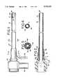
- FIG. 1is an elevational view, partially broken away, of a preferred illustration of an electrically conductive percutaneous unipolar vascular sheath introducer in accordance with the present invention
- FIG. 2is a transverse cross-sectional view through the sheath introducer embodiment illustrated in FIG. 1;
- FIG. 4is a cross-sectional view along the line 4--4 of FIG. 1;
- FIG. 5is an elevational illustration of a sheath introducer in accordance with the present invention shown within an in-use application.
- FIG. 6is a schematic view illustrating a procedure practiced in accordance with the present method of use and illustrating an in-use environment of the electrically conductive unipolar sheath introducer in accordance with the present invention.
- Sheath introducer 21includes an elongated conductive cannula shaft, generally designated as 22, and also includes a hub component 23 for facilitating attachment of the sheath introducer 21 to suitable treatment equipment and/or support devices, connectors and the like.
- Sheath introducer 21is designed to receive a device such as a catheter, generally designated as 24 in FIG. 5 and in FIG. 6.
- a typical catheter 24can include one or more electrodes. Illustrated in this regard are a ring electrode 25 and a tip electrode 26. Electrodes of this type will be in engagement with the body tissue to be treated or diagnosed, such as an internal surface of a heart 27 of a patient 28. See FIG. 6 for an illustration of a typical procedure in this regard.
- a conductor 31is in electrical communication with the elongated conductive cannula shaft 22. It typically will include a pin jack 32 or other suitable connector so as to provide electrical communication with the equipment used for mapping, ablation and the like. In some applications a hollow tube or side arm sheath 33 is included for flushing and/or for optional fluid administration through the sheath introducer 21.
- FIG. 5illustrates the following components useful in this regard.
- a cap assembly 34as shown in FIG. 5, as is a Luer cap 35.
- a collar structure 36 suitable for this useis also illustrated. These components are joined with a stopcock/tubing/collar assembly 37.
- a typical use of the present inventionis illustrated in FIG. 6.
- a puncture 38is made in the patient, for example in the groin area as illustrated.
- the sheath introducer 21is inserted inside the incision and into the blood vessel or the like. It will be appreciated by those skilled in the art that the puncture could be made in other areas of the body in order to gain access to the desired body cavity and/or body organ.
- the catheter 24is inserted into the open end which is generally along the axis of the sheath introducer. Both the sheath introducer 21 and the catheter 24 are thus within the patient's body, and the catheter is moved within the body vessel as desired. In the illustrated embodiment, this movement is to a location within the heart 27. More specifically, the catheter having its electrically conductive electrode is moved manually through the sheath, up through the patient's abdomen and thorax until it is in contact with the heart.
- the pin jack 32 or other suitable connector at the end of the conductor 31accesses the system to equipment needed for carrying out the desired medical procedure.
- this piece of equipmentcan be a recording apparatus for measuring the electrical potential of the heart.
- other equipmentcould be incorporated, such as energy generating equipment for carrying out ablation procedures and the like.
- the electrical circuitthus completed permits the electrical potential of the heart to be measured on the recorder.
- the electrical circuit thus completed through the conductor 31would allow for energy delivery, such as ablation energy, to be transmitted to the heart.
- the elongated conductive cannula shaft 22is a polymeric cylinder 41 which has been rendered electrically conductive by adding a metallic component to it.
- the metallic componenttakes the form of an extremely thin adherent film of metallic material so as to provide the polymeric cylinder 41 with a conductive surface.
- this conductive surfaceis an external conductive surface 42.
- Electrically conductive surface 42transforms the polymeric cylinder 41 into an indifferent electrode which is required for carrying out the procedures discussed herein.
- an internal conductive surface 43could be included if needed to provide adequate surface area for a particular metallic material.
- an internal conductive surfaceis not required and has a possible disadvantage of reducing flexibility of the cylinder 41 and can be susceptible to scratching when the catheter passes through.
- assemblycan be as follows. The tip of the conductor 31 is soldered to the inside surface of the band 44. The band is then press fitted onto a collar 45 of the sheath assembly. This assembly is then processed by an ion process deposition such that the electrically conductive surface covers the band 44 and at least a portion of the collar 45 in the area designated as 42a.
- the thin adherent metallic material coatingis provided over the entire cannula shaft, over the collar and over the stainless steel band in order to create an electrically conductive path from the distal tip of the sheath 46 to the stainless steel band 44, through the conductor 31 and to the pin jack or the like 32.
- a typical polymeric cylinder 41 of the cannula shaftwill be made of a material that is somewhat flexible but yet has adequate rigidity to perform as a cannula sheath. Included are polyamide elastomers which are relatively high on the Durometer hardness scale for polyamide elastomers. Typically, such hardnesses would be on the order of 60D and above.
- Other catheter sheath materialswhich can be formulated to provide the desired flexibility and strength are polyurethanes, polyethylenes, nylons including polyamide homopolymers and polyamide copolymers, and Teflon compounds.
- PEBAX 70D polyamidewhich is a polyester ether block copolymer of a nylon block with an ether block.
- the conductive surface of extremely thin film of metallic materialis preferably applied by ion process deposition of a metal element, metal alloy or metal compound onto the sheath.
- the conductive surfaceshould remain malleable enough to withstand flexing of the shaft without flaking off from the shaft. It is important that the metallic material be spread over a large surface area inasmuch as an enhanced surface area decreases impedance.
- the metallic material surface area of the sheathbe substantially greater than that of the electrode(s) 25 and/or 26 at the distal portion of the catheter 24. This difference in respective conductive surface areas substantially reduces or virtually eliminates the chance of surface heating of the indifferent electrode when the RF current is passed through the active electrode.
- An example of a suitable ion process deposition of the metallic materialis one available from Spire Corporation, of Bedford, Massachusetts. Some such processes are identified as SPI-ARGENT and SPI-MET (trademarks) procedures. Such are especially suitable for metallizing polymeric surfaces and can provide the desired thin film of metallic material that is characteristic of the present invention.
- the basic procedureis one of ion process deposition.
- processes suitable for the present inventioncan be characterized as achieving chemical vapor deposition.
- a rastered ion beam of a suitable chemicalcan also be applied such that the metallic material is "pounded” and bonded into the polymer by being bombarded by the ion beam.
- the resultis a very thin, highly adherent metallic material film that is both mechanically and chemically bonded to the polymeric cylinder 41.
- Surface area enlargement or enhancementcan also be achieved by further raster ion beam bombardment in order to "dimple" or texture the deposited metallic material surface.
- An exampleis the SPI-TEXT (trademark) process of Spire Corporation.
- Patents which disclosure these procedures and related equipment and specific materials and processing conditionsinclude U.S. Pat. Nos. 4,229,232, 4,443,488, 4,693,760, 4,743,493, 5,104,690, 5,118,400, 5,123,924, 5,133,757 and 5,236,509. These disclosures are incorporated by reference hereinto.
- a suitable very thin, highly adherent metallic material coatingwill be not greater than about 10 microns in thickness, preferably not greater than about 5 microns.
- a suitable exemplary thicknessis about 1 to 4 microns.
- Either a single metal, metal alloy or metal compound deposition or a multiple metallic material depositioncan be carried out.
- some metallic materialshave especially high conductivity or low resistivity while others, although having suitable electrical properties, are particularly well suited because of especially high biocompatibility or inertness within an in vivo setting, making them especially advantageous as an external coating.
- the conducting metallic materialshould have a resistivity of equal to or less than about 50 microhm-centimeters at 20° C. or that the entire sheath introducer should have a resistance of less than about 3 ohms at a coating thickness of about 10 microns or less.
- the metallic materialsshould also be biocompatible.
- Examples of materials that meet these resistivity and biocompatibility criteriainclude gold, Monel metal alloy, platinum, silver, steel alloys such as stainless steel, tantalum, titanium and titanium nitride.
- metallic materials suitable for use as pacemaker electrodesshould meet the criteria for the metallic material of the present invention.
- silver metalwas deposited by the Spire process to 3000 angstroms in thickness. Resistance was measured to be in the range of about 1 ohm, which generally corresponds to these data. For example, titanium deposited to a thickness of about 4 microns should show the resistance of the shaft to be on the order of 1.35 ohm. In other examples, titanium was deposited to a thickness of 500 angstroms, and titanium nitride was also suitably deposited. Desirably, the resistance of the sheath introducer at body temperature, 37° C., should be on the order of about 1 ohm or less. This resistance should occur for coating thicknesses of less than 10 microns, including those as thin as 3 or 4 microns, or less, as illustrated by the above data. Measured DC resistance should be 10 ohms or less, at 37° C.
- a PEBAX 70D polymeric cylinderis subjected to ion process deposition of silver.
- Thisprovides a base coating which is extremely electrically conductive.
- Thisis followed by ion process deposition of gold metal thereonto in order to enhance the inertness of the metallic material deposition to the body.
- the total metallic material thus coatedhad a thickness of approximately 2 microns.
- the resulting cannula sheath introducerwas found to function as an indifferent electrode having an extremely low resistance and a feel and appearance which is difficult to discern from the same introducer that does not exhibit the electrical properties of the present invention.
- Typical sheath cannula sizes in this regardare on the order of 6 French, 7 French and 8 French.
Landscapes
- Health & Medical Sciences (AREA)
- Heart & Thoracic Surgery (AREA)
- Nuclear Medicine, Radiotherapy & Molecular Imaging (AREA)
- Cardiology (AREA)
- Engineering & Computer Science (AREA)
- Biomedical Technology (AREA)
- Radiology & Medical Imaging (AREA)
- Life Sciences & Earth Sciences (AREA)
- Animal Behavior & Ethology (AREA)
- General Health & Medical Sciences (AREA)
- Public Health (AREA)
- Veterinary Medicine (AREA)
- Vascular Medicine (AREA)
- Media Introduction/Drainage Providing Device (AREA)
- Materials For Medical Uses (AREA)
Abstract
Description
The present invention generally relates to an electrically conductive percutaneous unipolar vascular sheath introducer having especially advantageous electrical properties. More particularly, the unipolar vascular sheath includes a conductive cannula shaft made of a polymeric material having an outer surface which is an adherent thin metallic material film that is of very low resistivity and that is chemically and/or mechanically bonded to the polymeric material of the cannula shaft in order to provide an indifferent electrode of low resistance.
Percutaneous vascular unipolar electrically conductive sheaths are generally described in Goldman U.S. Pat. No. 5,429,130, the disclosure thereof being incorporated by reference hereinto. In such devices, the sheath is inserted into the vascular system of a patient's body, the sheath serving as an indifferent electrode thereon and a conductor wire in electrical communication with the electrically conductive area on the outer coaxial surface of the sheath. This conductor is adapted to be connected to an external circuit. In addition, the sheath is adapted to receive a catheter having an electrode at its distal portion. When the external circuit is completed, with the inside being electrically insulated from the outside surface, it passes through the patient's body between the electrode of the catheter and the electrically conductive area of the sheath.
Devices such as these are intended for use in recording electrical signals Such as in carrying out mapping techniques. In addition, such devices can be for use in energy delivery to the patient's body, such as is accomplished in ablation procedures and related applications such as coagulation, electrical surgery and the like. For example, radio frequency (RF) current can be used. Devices of this type are suitable where an indifferent or ground connection is necessary.
The present invention is an improvement over devices such as those discussed hereinabove. The invention provides a sheath introducer having a cannula shaft that is both conductive and still flexible or malleable enough to be used in the same manner as, and to have substantially the same feel as, percutaneous vascular sheaths made principally of polymeric material and that are not conductive or that have a relatively small ring electrode or the like which does not substantially interfere with the flexibility or feel of the polymeric cannula shaft.
In summary, the present invention achieves certain objectives and provides advantageous properties by an electrically conductive percutaneous unipolar vascular sheath introducer which has a polymeric cannula shaft which is rendered conductive by having an elongated outer peripheral surface that is an electrically conductive surface which is an adherent, thin metallic material film that does not significantly alter the mechanical properties of the polymeric cannula shaft. This elongated conductive cannula shaft may function as an indifferent electrode which has an electrode surface area that is substantially coincident with the elongated outer peripheral surface of the cannula shaft. A conductor lead is in electrical communication with the electrically conductive surface of the cannula shaft. This arrangement allows the medical professional to insert an electrode-containing catheter into the body through the vascular sheath introducer. When, for example, the electrode of the catheter is in engagement with a portion of the heart, an electrical circuit can be provided between the catheter electrode and the external circuit, the circuit passing through the body and through the unipolar vascular sheath according to the invention.
It is accordingly a general object of the present invention to provide an improved electrically conductive sheath or cannula which is otherwise usable in the manner of a similarly sized sheath or cannula which is not electrically conductive.
Another object of the present invention is to provide an improved percutaneous unipolar vascular sheath introducer and method of providing and using same, which sheath introducer has a polymeric cannula shaft that is rendered electrically conductive over substantially its entire surface area.
Another object of the present invention is an improved electrically conductive percutaneous unipolar vascular sheath introducer and method of its preparation and use, which sheath introducer is polymeric and has been rendered electrically conductive by treatment with a conductive material on its surface.
Another object of the present invention is to provide an improved percutaneous unipolar vascular sheath that is electrically conductive over its surface and exhibits an extremely low resistance.
Another object of this invention is to provide an improved electrically conductive percutaneous unipolar vascular sheath which is primarily polymeric but which is treated with a very fine layer of treatment material that imparts its very low resistivity to substantially the entirety of the surface of the cannula shaft.
Another object of the present invention is to provide an improved sheath introducer which can act as an indifferent electrode for sensing or delivering current.
Another object of the present invention is to impart a metallic material coating to a sheath cannula which does not compromise or substantially impair the mechanical properties of the sheath cannula.
Another object of this invention is to provide a cannula having a metallic coating which actually enhances cannula mechanical tear and puncture resistance properties.
These and other objects, features and advantages of the present invention will be clearly understood through a consideration of the following detailed description.
In the course of this description, reference will be made to the attached drawings, wherein:
FIG. 1 is an elevational view, partially broken away, of a preferred illustration of an electrically conductive percutaneous unipolar vascular sheath introducer in accordance with the present invention;
FIG. 2 is a transverse cross-sectional view through the sheath introducer embodiment illustrated in FIG. 1;
FIG. 3 is a cross-sectional view along the line 3--3 of FIG. 1;
FIG. 4 is a cross-sectional view along the line 4--4 of FIG. 1;
FIG. 5 is an elevational illustration of a sheath introducer in accordance with the present invention shown within an in-use application; and
FIG. 6 is a schematic view illustrating a procedure practiced in accordance with the present method of use and illustrating an in-use environment of the electrically conductive unipolar sheath introducer in accordance with the present invention.
An illustration of a vascular sheath introducer that incorporates the present invention is generally designated as 21 in FIG. 1. Sheathintroducer 21 includes an elongated conductive cannula shaft, generally designated as 22, and also includes ahub component 23 for facilitating attachment of the sheath introducer 21 to suitable treatment equipment and/or support devices, connectors and the like. Sheath introducer 21 is designed to receive a device such as a catheter, generally designated as 24 in FIG. 5 and in FIG. 6. As illustrated in FIG. 5, atypical catheter 24 can include one or more electrodes. Illustrated in this regard are aring electrode 25 and atip electrode 26. Electrodes of this type will be in engagement with the body tissue to be treated or diagnosed, such as an internal surface of aheart 27 of apatient 28. See FIG. 6 for an illustration of a typical procedure in this regard.
Aconductor 31 is in electrical communication with the elongatedconductive cannula shaft 22. It typically will include apin jack 32 or other suitable connector so as to provide electrical communication with the equipment used for mapping, ablation and the like. In some applications a hollow tube orside arm sheath 33 is included for flushing and/or for optional fluid administration through the sheath introducer 21. FIG. 5 illustrates the following components useful in this regard. In addition to the cannula sheath introducerassembly 21, there is also provided acap assembly 34 as shown in FIG. 5, as is aLuer cap 35. Acollar structure 36 suitable for this use is also illustrated. These components are joined with a stopcock/tubing/collar assembly 37.
A typical use of the present invention is illustrated in FIG. 6. Apuncture 38 is made in the patient, for example in the groin area as illustrated. The sheath introducer 21 is inserted inside the incision and into the blood vessel or the like. It will be appreciated by those skilled in the art that the puncture could be made in other areas of the body in order to gain access to the desired body cavity and/or body organ. Thecatheter 24 is inserted into the open end which is generally along the axis of the sheath introducer. Both the sheath introducer 21 and thecatheter 24 are thus within the patient's body, and the catheter is moved within the body vessel as desired. In the illustrated embodiment, this movement is to a location within theheart 27. More specifically, the catheter having its electrically conductive electrode is moved manually through the sheath, up through the patient's abdomen and thorax until it is in contact with the heart.
Thepin jack 32 or other suitable connector at the end of theconductor 31 accesses the system to equipment needed for carrying out the desired medical procedure. For example, when mapping is to be accomplished, this piece of equipment (not shown) can be a recording apparatus for measuring the electrical potential of the heart. Alternatively, other equipment could be incorporated, such as energy generating equipment for carrying out ablation procedures and the like. It will be appreciated that thus two electrical contacts are provided within the body, one by the electrode(s) of thecatheter 24, and the other the electrically conductive portions of the sheath introducer 21. The electrical circuit thus completed permits the electrical potential of the heart to be measured on the recorder. Alternatively, the electrical circuit thus completed through theconductor 31 would allow for energy delivery, such as ablation energy, to be transmitted to the heart.
More particular reference is now made to the embodiments of thesheath introducer 21 which are illustrated, particularly in FIG. 1 through FIG. 4. The elongatedconductive cannula shaft 22 is apolymeric cylinder 41 which has been rendered electrically conductive by adding a metallic component to it. In the embodiment illustrated in the drawings, the metallic component takes the form of an extremely thin adherent film of metallic material so as to provide thepolymeric cylinder 41 with a conductive surface. In the preferred illustrated embodiment, this conductive surface is an externalconductive surface 42. Electricallyconductive surface 42 transforms thepolymeric cylinder 41 into an indifferent electrode which is required for carrying out the procedures discussed herein. Optionally, an internalconductive surface 43 could be included if needed to provide adequate surface area for a particular metallic material. Typically, an internal conductive surface is not required and has a possible disadvantage of reducing flexibility of thecylinder 41 and can be susceptible to scratching when the catheter passes through.
In addition, it is necessary to provide secure electrical communication between the electrically conductivepolymeric cylinder 41 and theconductor 31. In the illustrated embodiment, such is achieved by incorporating a conductive assembly component such as the illustratedstainless steel band 44. With this arrangement, assembly can be as follows. The tip of theconductor 31 is soldered to the inside surface of theband 44. The band is then press fitted onto acollar 45 of the sheath assembly. This assembly is then processed by an ion process deposition such that the electrically conductive surface covers theband 44 and at least a portion of thecollar 45 in the area designated as 42a. As a result, the thin adherent metallic material coating is provided over the entire cannula shaft, over the collar and over the stainless steel band in order to create an electrically conductive path from the distal tip of thesheath 46 to thestainless steel band 44, through theconductor 31 and to the pin jack or the like 32.
As an alternative assembly approach, one could first apply the adherent metallic material coating onto the cannula shaft. Thereafter, one would then press fit thestainless steel band 44 and the conductor end over the metallicized shaft and/ormetallicized collar 45. In this instance as well, an electrically conductive path is provided from thedistal tip 46 to the pin jack or the like 32.
Atypical polymeric cylinder 41 of the cannula shaft will be made of a material that is somewhat flexible but yet has adequate rigidity to perform as a cannula sheath. Included are polyamide elastomers which are relatively high on the Durometer hardness scale for polyamide elastomers. Typically, such hardnesses would be on the order of 60D and above. Other catheter sheath materials which can be formulated to provide the desired flexibility and strength are polyurethanes, polyethylenes, nylons including polyamide homopolymers and polyamide copolymers, and Teflon compounds. An exemplary polyamide material that is used in current sheaths that are typically not of the electrically conductive type but which can be modified according to the present invention is PEBAX 70D polyamide, which is a polyester ether block copolymer of a nylon block with an ether block.
The conductive surface of extremely thin film of metallic material is preferably applied by ion process deposition of a metal element, metal alloy or metal compound onto the sheath. The conductive surface should remain malleable enough to withstand flexing of the shaft without flaking off from the shaft. It is important that the metallic material be spread over a large surface area inasmuch as an enhanced surface area decreases impedance. For example, it is advantageous that the metallic material surface area of the sheath be substantially greater than that of the electrode(s) 25 and/or 26 at the distal portion of thecatheter 24. This difference in respective conductive surface areas substantially reduces or virtually eliminates the chance of surface heating of the indifferent electrode when the RF current is passed through the active electrode.
An example of a suitable ion process deposition of the metallic material is one available from Spire Corporation, of Bedford, Massachusetts. Some such processes are identified as SPI-ARGENT and SPI-MET (trademarks) procedures. Such are especially suitable for metallizing polymeric surfaces and can provide the desired thin film of metallic material that is characteristic of the present invention. The basic procedure is one of ion process deposition.
Generally speaking, processes suitable for the present invention can be characterized as achieving chemical vapor deposition. A rastered ion beam of a suitable chemical can also be applied such that the metallic material is "pounded" and bonded into the polymer by being bombarded by the ion beam. The result is a very thin, highly adherent metallic material film that is both mechanically and chemically bonded to thepolymeric cylinder 41. Surface area enlargement or enhancement can also be achieved by further raster ion beam bombardment in order to "dimple" or texture the deposited metallic material surface. An example is the SPI-TEXT (trademark) process of Spire Corporation.
Patents which disclosure these procedures and related equipment and specific materials and processing conditions include U.S. Pat. Nos. 4,229,232, 4,443,488, 4,693,760, 4,743,493, 5,104,690, 5,118,400, 5,123,924, 5,133,757 and 5,236,509. These disclosures are incorporated by reference hereinto.
It will be appreciated that, if the film is too thick, it will rigidify the polymeric cylinder too severely, and it will lose the flexibility and feel normally associated with catheter sheath introducers. If the metallic material does not adhere adequately and merely encapsulates the polymeric surface, rather than being bonded to it and into it, delamination will be a problem. Also, a very thin material which is well bonded to and into the surface of the polymeric material will run substantially no risk of interfering with or "catching" around thepuncture 38 or elsewhere when structures such as ring electrodes or strip electrodes are avoided. The metallic material coating does not significantly negatively modify the mechanical properties of the sheath cannula and in fact can enhance mechanical tear and puncture resistance properties.
A suitable very thin, highly adherent metallic material coating will be not greater than about 10 microns in thickness, preferably not greater than about 5 microns. A suitable exemplary thickness is about 1 to 4 microns. Either a single metal, metal alloy or metal compound deposition or a multiple metallic material deposition can be carried out. For example, some metallic materials have especially high conductivity or low resistivity while others, although having suitable electrical properties, are particularly well suited because of especially high biocompatibility or inertness within an in vivo setting, making them especially advantageous as an external coating.
It has been found that the conducting metallic material should have a resistivity of equal to or less than about 50 microhm-centimeters at 20° C. or that the entire sheath introducer should have a resistance of less than about 3 ohms at a coating thickness of about 10 microns or less. The metallic materials should also be biocompatible.
Examples of materials that meet these resistivity and biocompatibility criteria include gold, Monel metal alloy, platinum, silver, steel alloys such as stainless steel, tantalum, titanium and titanium nitride. Generally, metallic materials suitable for use as pacemaker electrodes should meet the criteria for the metallic material of the present invention.
The following is a listing of metallic elements or metallic alloys that exhibit the desired resistivity and theoretical resistance discussed herein. These data are theoretical resistance calculations for selected conductors. The cannula segment length used was 10.8 cm, and the size used was 8F, its outer diameter being 0.2667 cm. These resistivity and resistance calculations are as follows:
______________________________________ Resistivity Cannula Theoretical Metallic Coating and at 20° C. Resistance at 37° C. Material Thickness (Microhms-cm) (ohms) ______________________________________ gold 3 2.44 1.37 gold 4 2.44 0.10 Monel metal 3 42 19.38 Monel metal 4 42 1.45 platinum 3 10.6 5.22 platinum 4 10.6 0.39 silver 3 1.59 0.84 silver 4 1.59 0.06 steel (E.B.B) 3 10.4 5.29 steel (E.B.B) 4 10.4 0.40 tantalum 3 15.5 7.42 tantalum 4 15.5 0.56 titanium 3 42 18.05 titanium 4 42 1.35 ______________________________________
In an exemplary procedure, silver metal was deposited by the Spire process to 3000 angstroms in thickness. Resistance was measured to be in the range of about 1 ohm, which generally corresponds to these data. For example, titanium deposited to a thickness of about 4 microns should show the resistance of the shaft to be on the order of 1.35 ohm. In other examples, titanium was deposited to a thickness of 500 angstroms, and titanium nitride was also suitably deposited. Desirably, the resistance of the sheath introducer at body temperature, 37° C., should be on the order of about 1 ohm or less. This resistance should occur for coating thicknesses of less than 10 microns, including those as thin as 3 or 4 microns, or less, as illustrated by the above data. Measured DC resistance should be 10 ohms or less, at 37° C.
In an especially preferred arrangement, a PEBAX 70D polymeric cylinder is subjected to ion process deposition of silver. This provides a base coating which is extremely electrically conductive. This is followed by ion process deposition of gold metal thereonto in order to enhance the inertness of the metallic material deposition to the body. The total metallic material thus coated had a thickness of approximately 2 microns. The resulting cannula sheath introducer was found to function as an indifferent electrode having an extremely low resistance and a feel and appearance which is difficult to discern from the same introducer that does not exhibit the electrical properties of the present invention. Typical sheath cannula sizes in this regard are on the order of 6 French, 7 French and 8 French.
It will be understood that the embodiments of the present invention which have been described are illustrative some of the applications of the principles of the present invention. Numerous modifications may be made by those skilled in the art without departing from the true spirit and scope of the invention.
Claims (29)
1. An electrically conductive percutaneous unipolar vascular sheath introducer, comprising:
an elongated conductive cannula shaft having a generally cylindrical shaft component made of polymeric material, said elongated conductive cannula shaft having a proximal end portion, a distal end portion, an elongated generally cylindrical outer surface and an elongated generally cylindrical inner surface defining an elongated bore for receiving a catheter;
a hub secured to said proximal portion of the elongated conductive cannula shaft;
said elongated generally cylindrical outer surface is an electrically conductive surface which is an adherent thin metallic material film;
a conductor lead electrically connected to said elongated electrically conductive generally cylindrical outer surface, said elongated conductive cannula shaft being an indifferent electrode having a surface area substantially coincident with at least said elongated generally cylindrical outer surface; and
said metallic material film is a multilayered film having an internal silver layer of exceedingly low resistivity and an outer gold layer of low resistivity and exceedingly high inertness, the resistivity of the internal layer being less than the resistivity of the outer layer, and the inertness of the outer layer being greater than that of the internal layer.
2. The electrically conductive sheath introducer in accordance with claim 1, wherein said metallic surface is of a metallic material having a resistivity of not greater than about 50 microhm-centimeters at 20° C.
3. The electrically conductive sheath introducer in accordance with claim 1, wherein said metallic surface has a thickness of not greater than about 10 microns and has a resistance of not greater than about 3 ohms.
4. The electrically conductive sheath introducer in accordance with claim 1, wherein said conductor lead is electrically connected to said outer surface with a band that is electrically conductive.
5. The electrically conductive sheath introducer in accordance with claim 4, wherein said adherent thin metallic material film is substantially continuous along said generally cylindrical outer surface and said band.
6. The electrically conductive sheath introducer in accordance with claim 4, wherein said metallic material film extends from said distal end portion of the shaft component to said band.
7. The electrically conductive sheath introducer in accordance with claim 1, wherein said metallic material film extends from said distal end portion of the shaft component to the location at which said conductor lead is electrically connected to said shaft component.
8. The electrically conductive sheath introducer in accordance with claim 1, wherein said metallic surface has a thickness of not greater than about 5 microns.
9. The electrically conductive sheath introducer in accordance with claim 1, wherein said indifferent electrode of the sheath introducer has a resistance of not greater than approximately 2 ohms.
10. The electrically conductive sheath introducer in accordance with claim 1, wherein said indifferent electrode of the sheath introducer has a resistance of not greater than approximately 1 ohm.
11. The electrically conductive sheath introducer in accordance with claim 1, wherein said metallic material film is selected from the group consisting of gold, platinum, silver, tantalum and titanium materials.
12. An electrically conductive percutaneous unipolar vascular sheath introducer, comprising:
an elongated conductive cannula shaft having a generally cylindrical shaft component made of polymeric material, said elongated conductive cannula shaft having a proximal end portion, a distal end portion, an elongated generally cylindrical outer surface and an elongated generally cylindrical inner surface defining an elongated bore for receiving a catheter;
a hub secured to said proximal portion of the elongated conductive cannula shaft;
said elongated generally cylindrical outer surface is an electrically conductive surface which is an adherent thin metallic material film;
a conductor lead electrically connected to said elongated electrically conductive generally cylindrical outer surface, said elongated conductive cannula shaft being an indifferent electrode having a surface area substantially coincident with at least said elongated generally cylindrical outer surface; and
said elongated generally cylindrical inner surface is an electrically conductive surface which is an adherent thin metallic material film, and said electrically conductive inner surface is included in said indifferent electrode, said indifferent electrode having a surface area substantially coincident with both said elongated outer surface and said elongated inner surface.
13. The electrically conductive sheath introducer in accordance with claim 12, wherein said metallic outer surface is of a metallic material having a resistivity of not greater than about 50 microhm-centimeters at 20° C.
14. The electrically conductive sheath introducer in accordance with claim 12, wherein said metallic outer surface has a thickness of not greater than about 10 microns and has a resistance of not greater than about 3 ohms.
15. The electrically conductive sheath introducer in accordance with claim 12, wherein said conductor lead is electrically connected to said outer surface with a band that is electrically conductive.
16. The electrically conductive sheath introducer in accordance with claim 15, wherein said outer surface adherent thin metallic material film is substantially continuous along said generally cylindrical outer surface and said band.
17. The electrically conductive sheath introducer in accordance with claim 15, wherein said outer surface metallic material film extends from said distal end portion of the shaft component to said band.
18. The electrically conductive sheath introducer in accordance with claim 12, wherein said outer surface metallic material film extends from said distal end portion of the shaft component to the location at which said conductor lead is electrically connected to said shaft component.
19. The electrically conductive sheath introducer in accordance with claim 12, wherein said metallic outer surface has a thickness of not greater than about 5 microns.
20. The electrically conductive sheath introducer in accordance with claim 12, wherein said indifferent electrode of the sheath introducer has a resistance of not greater than approximately 2 ohms.
21. The electrically conductive sheath introducer in accordance with claim 12, wherein said indifferent electrode of the sheath introducer has a resistance of not greater than approximately 1 ohm.
22. The electrically conductive sheath introducer in accordance with claim 12, wherein said outer surface metallic material film is selected from the group consisting of gold, platinum, silver, tantalum and titanium.
23. The electrically conductive sheath introducer in accordance with claim 12, wherein said outer surface metallic material film is a multilayered film having an internal layer of exceedingly low resistivity and an outer layer of low resistivity and exceedingly high inertness, the resistivity of the internal layer being greater than the resistivity of the outer layer, and the inertness of the outer layer being greater than that of the internal layer.
24. The electrically conductive sheath introducer in accordance with claim 23, wherein said internal layer is silver and said outer layer is gold.
25. A catheter and sheath introducer assembly, comprising:
a catheter having an elongated flexible shaft, a hub at a proximal portion thereof, and an electrode at a distal portion thereof;
an electrically conductive percutaneous vascular sheath introducer including:
an elongated conductive cannula shaft having a generally cylindrical shaft component made of polymeric material, said elongated conductive cannula shaft having a proximal end portion, a distal end portion, an elongated generally cylindrical outer surface and an elongated generally cylindrical inner surface defining an elongated bore for receiving said catheter,
a hub secured to said proximal portion of the elongated conductive cannula shaft,
said elongated generally cylindrical outer surface is an electrically conductive surface which is an adherent thin metallic material film,
a conductor lead electrically connected to said elongated electrically conductive generally cylindrical outer surface, said elongated conductive cannula shaft being an indifferent electrode having a surface area substantially coincident with at least said elongated generally cylindrical outer surface;
said conductor lead is adapted to be electrically connected to a circuit external of a patient's body, and said indifferent electrode is adapted to be a component of an electrical circuit passing through patient's body between the electrode of the catheter and the elongated conductive cannula shaft, wherein the metallic surface is a textured metallic surface which is mechanically bonded and chemically bonded by chemical vapor deposition ion beam bombardment to said elongated generally cylindrical outer surface of the shaft component made of polymeric material; and
said elongated generally cylindrical inner surface includes an electrically conductive surface which is an adherent thin metallic material film, and said inner electrically conductive surface is included in said indifferent electrode.
26. The assembly in accordance with claim 25, wherein said metallic surface is of a metallic material having a resistivity of not greater than about 50 microhm-centimeters at 20° C.
27. The assembly in accordance with claim 25, wherein said metallic surface has a thickness of not greater than about 10 microns and has a resistance of not greater than about 3 ohms.
28. The assembly in accordance with claim 25, wherein said metallic material film extends from said distal end portion of the shaft component to the location at which said conductor lead is electrically connected to said shaft location.
29. The assembly in accordance with claim 25, wherein said electrode of the catheter has a surface area which is substantially less than that of said indifferent electrode of the sheath introducer.
Priority Applications (1)
| Application Number | Priority Date | Filing Date | Title |
|---|---|---|---|
| US08/558,641US5733323A (en) | 1995-11-13 | 1995-11-13 | Electrically conductive unipolar vascular sheath |
Applications Claiming Priority (1)
| Application Number | Priority Date | Filing Date | Title |
|---|---|---|---|
| US08/558,641US5733323A (en) | 1995-11-13 | 1995-11-13 | Electrically conductive unipolar vascular sheath |
Publications (1)
| Publication Number | Publication Date |
|---|---|
| US5733323Atrue US5733323A (en) | 1998-03-31 |
Family
ID=24230348
Family Applications (1)
| Application Number | Title | Priority Date | Filing Date |
|---|---|---|---|
| US08/558,641Expired - LifetimeUS5733323A (en) | 1995-11-13 | 1995-11-13 | Electrically conductive unipolar vascular sheath |
Country Status (1)
| Country | Link |
|---|---|
| US (1) | US5733323A (en) |
Cited By (93)
| Publication number | Priority date | Publication date | Assignee | Title |
|---|---|---|---|---|
| US5849020A (en)* | 1997-06-30 | 1998-12-15 | Ethicon Endo-Surgery, Inc. | Inductively coupled electrosurgical instrument |
| US5925041A (en)* | 1997-05-14 | 1999-07-20 | Ethicon Endo-Surgery, Inc. | Monopolar electrosurgical trocar |
| US5951552A (en)* | 1997-06-30 | 1999-09-14 | Ethicon Endo-Surgery, Inc. | Capacitively coupled cordless electrosurgical instrument |
| US5961514A (en)* | 1997-05-14 | 1999-10-05 | Ethicon Endo-Surger, Inc. | Cordless electrosurgical instrument |
| US5984921A (en)* | 1997-05-14 | 1999-11-16 | Ethicon-Endo-Surgery, Inc. | Method and apparatus for applying electrical energy to medical instruments |
| US6062902A (en)* | 1998-09-28 | 2000-05-16 | Ge Marquette Medical Systems | Connector for catheter electrode |
| US6106519A (en)* | 1997-06-30 | 2000-08-22 | Ethicon Endo-Surgery, Inc. | Capacitively coupled electrosurgical trocar |
| US6117132A (en)* | 1997-06-30 | 2000-09-12 | Ethicon Endo-Surgery, Inc. | Inductively coupled electrosurgical trocar |
| US6475214B1 (en) | 2000-05-01 | 2002-11-05 | Biosense Webster, Inc. | Catheter with enhanced ablation electrode |
| US20030236505A1 (en)* | 2000-07-21 | 2003-12-25 | Frank Bonadio | Cannula |
| US6671561B1 (en) | 2000-05-01 | 2003-12-30 | Biosense Webster, Inc. | Catheter with electrode having hydrogel layer |
| US20040186545A1 (en)* | 2003-03-20 | 2004-09-23 | Rosero Spencer Z. | Temporary percutaneous cardioverter-defibrillator |
| US20050225735A1 (en)* | 2002-12-10 | 2005-10-13 | Nikon Corporation | Exposure apparatus and method for producing device |
| US20070016072A1 (en)* | 2005-05-06 | 2007-01-18 | Sorin Grunwald | Endovenous access and guidance system utilizing non-image based ultrasound |
| US20070083195A1 (en)* | 2005-07-11 | 2007-04-12 | Werneth Randell L | Low power tissue ablation system |
| US20080281312A1 (en)* | 2007-05-11 | 2008-11-13 | Ablation Frontiers, Inc. | Ablation Therapy System and Method for Treating Continuous Atrial Fibrillation |
| US20080306477A1 (en)* | 2004-11-24 | 2008-12-11 | Kunis Christopher G | Atrial ablation catheter and method of use |
| US20080319499A1 (en)* | 2004-12-20 | 2008-12-25 | Qingsheng Zhu | Devices and Methods for Steering Electrical Stimulation in Cardiac Rhythm Management |
| US20080319501A1 (en)* | 2004-12-20 | 2008-12-25 | Qingsheng Zhu | Systems, Devices and Methods for Monitoring Efficiency of Pacing |
| US20090005830A1 (en)* | 2004-12-20 | 2009-01-01 | Qingsheng Zhu | Endocardial Pacing Relating to Conduction Abnormalities |
| US20090005846A1 (en)* | 2004-12-20 | 2009-01-01 | Qingsheng Zhu | Methods, Devices and Systems for Cardiac Rhythm Management Using an Electrode Arrangement |
| US20090005675A1 (en)* | 2005-05-06 | 2009-01-01 | Sorin Grunwald | Apparatus and Method for Endovascular Device Guiding and Positioning Using Physiological Parameters |
| US20090030411A1 (en)* | 2004-10-14 | 2009-01-29 | Werneth Randell L | Ablation catheter |
| DE102007037989A1 (en)* | 2007-08-10 | 2009-02-19 | Martin-Luther-Universität Halle-Wittenberg | Percutaneous transluminal coronary angioplasty-guiding catheter for transcoronary myocardial stimulation during coronary intervention, has electrode integrated into catheter through coil or through vaporization of conductor |
| US20090093861A1 (en)* | 2004-12-20 | 2009-04-09 | Action Medical, Inc. | Methods for treating the physiological electric conduction of the heart |
| US20090118612A1 (en)* | 2005-05-06 | 2009-05-07 | Sorin Grunwald | Apparatus and Method for Vascular Access |
| US20090177069A1 (en)* | 2008-01-04 | 2009-07-09 | Mehdi Razavi | Catheter with electrodes for impedance and/or conduction velocity measurement |
| US20090210029A1 (en)* | 2008-02-14 | 2009-08-20 | Pajunk Gmbh & Co. Kg Besitzverwaltung | Device and method to position a cannula for nerve block |
| US20100158656A1 (en)* | 2008-12-18 | 2010-06-24 | Seavey Nathaniel J M | Robot arm assembly |
| US20100174170A1 (en)* | 2009-01-05 | 2010-07-08 | Texas Heart Institute | Introducer sheath with electrodes |
| US20100174169A1 (en)* | 2009-01-05 | 2010-07-08 | Mehdi Razavi | Introducer sheathe with electrodes |
| US7850685B2 (en) | 2005-06-20 | 2010-12-14 | Medtronic Ablation Frontiers Llc | Ablation catheter |
| US20110087107A1 (en)* | 2009-10-08 | 2011-04-14 | C.R. Bard, Inc. | Spacers for use with an ultrasound probe |
| WO2011019760A3 (en)* | 2009-08-10 | 2011-06-16 | Romedex International Srl | Devices and methods for endovascular electrography |
| US8005544B2 (en) | 2004-12-20 | 2011-08-23 | Cardiac Pacemakers, Inc. | Endocardial pacing devices and methods useful for resynchronization and defibrillation |
| US8014861B2 (en) | 2004-12-20 | 2011-09-06 | Cardiac Pacemakers, Inc. | Systems, devices and methods relating to endocardial pacing for resynchronization |
| US8050756B2 (en) | 2004-12-20 | 2011-11-01 | Cardiac Pacemakers, Inc. | Circuit-based devices and methods for pulse control of endocardial pacing in cardiac rhythm management |
| US20110306970A1 (en)* | 2010-06-14 | 2011-12-15 | Mehdi Razavi | Sheath And Method Of Use |
| US20120053581A1 (en)* | 2009-02-12 | 2012-03-01 | Frederik Henricus Mattheus Wittkampf | Ablation Catheter and Method for Electrically Isolating Cardiac Tissue |
| US8290586B2 (en) | 2004-12-20 | 2012-10-16 | Cardiac Pacemakers, Inc. | Methods, devices and systems for single-chamber pacing using a dual-chamber pacing device |
| US8388541B2 (en) | 2007-11-26 | 2013-03-05 | C. R. Bard, Inc. | Integrated system for intravascular placement of a catheter |
| US8388546B2 (en) | 2006-10-23 | 2013-03-05 | Bard Access Systems, Inc. | Method of locating the tip of a central venous catheter |
| US8437833B2 (en) | 2008-10-07 | 2013-05-07 | Bard Access Systems, Inc. | Percutaneous magnetic gastrostomy |
| US8478382B2 (en) | 2008-02-11 | 2013-07-02 | C. R. Bard, Inc. | Systems and methods for positioning a catheter |
| US8512256B2 (en) | 2006-10-23 | 2013-08-20 | Bard Access Systems, Inc. | Method of locating the tip of a central venous catheter |
| US8565880B2 (en) | 2010-04-27 | 2013-10-22 | Cardiac Pacemakers, Inc. | His-bundle capture verification and monitoring |
| US8617152B2 (en) | 2004-11-15 | 2013-12-31 | Medtronic Ablation Frontiers Llc | Ablation system with feedback |
| USD699359S1 (en) | 2011-08-09 | 2014-02-11 | C. R. Bard, Inc. | Ultrasound probe head |
| US8657814B2 (en) | 2005-08-22 | 2014-02-25 | Medtronic Ablation Frontiers Llc | User interface for tissue ablation system |
| US8688234B2 (en) | 2008-12-19 | 2014-04-01 | Cardiac Pacemakers, Inc. | Devices, methods, and systems including cardiac pacing |
| US8761880B2 (en) | 2011-03-14 | 2014-06-24 | Cardiac Pacemakers, Inc. | His capture verification using electro-mechanical delay |
| US8781555B2 (en) | 2007-11-26 | 2014-07-15 | C. R. Bard, Inc. | System for placement of a catheter including a signal-generating stylet |
| US8784336B2 (en) | 2005-08-24 | 2014-07-22 | C. R. Bard, Inc. | Stylet apparatuses and methods of manufacture |
| US8801693B2 (en) | 2010-10-29 | 2014-08-12 | C. R. Bard, Inc. | Bioimpedance-assisted placement of a medical device |
| US8849382B2 (en) | 2007-11-26 | 2014-09-30 | C. R. Bard, Inc. | Apparatus and display methods relating to intravascular placement of a catheter |
| US8965490B2 (en) | 2012-05-07 | 2015-02-24 | Vasonova, Inc. | Systems and methods for detection of the superior vena cava area |
| USD724745S1 (en) | 2011-08-09 | 2015-03-17 | C. R. Bard, Inc. | Cap for an ultrasound probe |
| US9005194B2 (en) | 2004-11-24 | 2015-04-14 | Medtronic Ablation Frontiers Llc | Atrial ablation catheter adapted for treatment of septal wall arrhythmogenic foci and method of use |
| US9078627B2 (en) | 2008-01-04 | 2015-07-14 | Texas Heart Institute | Introducer sheath with electrodes |
| US9119551B2 (en) | 2010-11-08 | 2015-09-01 | Vasonova, Inc. | Endovascular navigation system and method |
| US9125578B2 (en) | 2009-06-12 | 2015-09-08 | Bard Access Systems, Inc. | Apparatus and method for catheter navigation and tip location |
| US9211107B2 (en) | 2011-11-07 | 2015-12-15 | C. R. Bard, Inc. | Ruggedized ultrasound hydrogel insert |
| US9339206B2 (en) | 2009-06-12 | 2016-05-17 | Bard Access Systems, Inc. | Adaptor for endovascular electrocardiography |
| US9440047B1 (en) | 2013-03-14 | 2016-09-13 | Angiodynamics, Inc. | Systems and methods for catheter tip placement using ECG |
| US9445746B1 (en) | 2013-03-14 | 2016-09-20 | Angio Dynamics, Inc. | Systems and methods for catheter tip placement using ECG |
| US9456766B2 (en) | 2007-11-26 | 2016-10-04 | C. R. Bard, Inc. | Apparatus for use with needle insertion guidance system |
| US9492097B2 (en) | 2007-11-26 | 2016-11-15 | C. R. Bard, Inc. | Needle length determination and calibration for insertion guidance system |
| US9521961B2 (en) | 2007-11-26 | 2016-12-20 | C. R. Bard, Inc. | Systems and methods for guiding a medical instrument |
| US9532724B2 (en) | 2009-06-12 | 2017-01-03 | Bard Access Systems, Inc. | Apparatus and method for catheter navigation using endovascular energy mapping |
| US9554716B2 (en) | 2007-11-26 | 2017-01-31 | C. R. Bard, Inc. | Insertion guidance system for needles and medical components |
| US9636031B2 (en) | 2007-11-26 | 2017-05-02 | C.R. Bard, Inc. | Stylets for use with apparatus for intravascular placement of a catheter |
| US9649048B2 (en) | 2007-11-26 | 2017-05-16 | C. R. Bard, Inc. | Systems and methods for breaching a sterile field for intravascular placement of a catheter |
| US20170332881A1 (en)* | 2015-02-27 | 2017-11-23 | Olympus Corporation | Medical power supply system |
| US9839372B2 (en) | 2014-02-06 | 2017-12-12 | C. R. Bard, Inc. | Systems and methods for guidance and placement of an intravascular device |
| US9901714B2 (en) | 2008-08-22 | 2018-02-27 | C. R. Bard, Inc. | Catheter assembly including ECG sensor and magnetic assemblies |
| US20180071092A1 (en)* | 2015-04-07 | 2018-03-15 | Benjamin FAURIE | Assembly for replacing a heart valve or coronary angioplasty assembly including a delivery catheter with or without introducer |
| WO2018065523A1 (en)* | 2016-10-07 | 2018-04-12 | Electroducer | Assembly for replacing a heart valve or a coronary angioplasty assembly |
| FR3057153A1 (en)* | 2016-10-07 | 2018-04-13 | Benjamin FAURIE | ELECTRICAL CONDUCTIVE SLEEVE FOR A DELIVERY OR INTRODUCING CATHETER OF A REPLACEMENT ASSEMBLY OF A CARDIAC VALVE OR A CORONARY ANGIOPLASTY ASSEMBLY |
| US10046139B2 (en) | 2010-08-20 | 2018-08-14 | C. R. Bard, Inc. | Reconfirmation of ECG-assisted catheter tip placement |
| US10188831B2 (en) | 2013-03-14 | 2019-01-29 | Angiodynamics, Inc. | Systems and methods for catheter tip placement using ECG |
| US10349890B2 (en) | 2015-06-26 | 2019-07-16 | C. R. Bard, Inc. | Connector interface for ECG-based catheter positioning system |
| WO2019185880A1 (en)* | 2018-03-29 | 2019-10-03 | Electroducer | Assembly for placement of a cardiac, aortic or arterial implant with stimulation assistance by a peripheral venous or arterial catheter |
| FR3079404A1 (en)* | 2018-03-29 | 2019-10-04 | Benjamin FAURIE | CARDIAC VALVE REPLACEMENT ASSEMBLY WITH PERIPHERAL ARTERIAL OR VENOUS STIMULATION ASSISTANCE |
| US10449330B2 (en) | 2007-11-26 | 2019-10-22 | C. R. Bard, Inc. | Magnetic element-equipped needle assemblies |
| US10524691B2 (en) | 2007-11-26 | 2020-01-07 | C. R. Bard, Inc. | Needle assembly including an aligned magnetic element |
| US10639008B2 (en) | 2009-10-08 | 2020-05-05 | C. R. Bard, Inc. | Support and cover structures for an ultrasound probe head |
| US10751509B2 (en) | 2007-11-26 | 2020-08-25 | C. R. Bard, Inc. | Iconic representations for guidance of an indwelling medical device |
| US10820885B2 (en) | 2012-06-15 | 2020-11-03 | C. R. Bard, Inc. | Apparatus and methods for detection of a removable cap on an ultrasound probe |
| US10973584B2 (en) | 2015-01-19 | 2021-04-13 | Bard Access Systems, Inc. | Device and method for vascular access |
| US10992079B2 (en) | 2018-10-16 | 2021-04-27 | Bard Access Systems, Inc. | Safety-equipped connection systems and methods thereof for establishing electrical connections |
| US11000207B2 (en) | 2016-01-29 | 2021-05-11 | C. R. Bard, Inc. | Multiple coil system for tracking a medical device |
| US11607150B2 (en) | 2014-04-08 | 2023-03-21 | Angiodynamics Va Llc | Medical device placement system and a method for its use |
| US20230181179A1 (en)* | 2020-05-19 | 2023-06-15 | Smartwise Sweden Ab | Endoluminal delivery cannula and assembly, and related methods |
Citations (17)
| Publication number | Priority date | Publication date | Assignee | Title |
|---|---|---|---|---|
| US452220A (en)* | 1891-05-12 | gunning | ||
| US4440108A (en)* | 1982-09-24 | 1984-04-03 | Spire Corporation | Ion beam coating apparatus |
| US4526637A (en)* | 1982-01-29 | 1985-07-02 | The Goodyear Tire & Rubber Company | Method of making conveyor belt |
| US4611604A (en)* | 1983-01-11 | 1986-09-16 | Siemens Aktiengesellschaft | Bipolar electrode for medical applications |
| US4693760A (en)* | 1986-05-12 | 1987-09-15 | Spire Corporation | Ion implanation of titanium workpieces without surface discoloration |
| US4743493A (en)* | 1986-10-06 | 1988-05-10 | Spire Corporation | Ion implantation of plastics |
| US4855026A (en)* | 1988-06-02 | 1989-08-08 | Spire Corporation | Sputter enhanced ion implantation process |
| US4968006A (en)* | 1989-07-21 | 1990-11-06 | Spire Corporation | Ion implantation of spherical surfaces |
| US5098483A (en)* | 1989-09-05 | 1992-03-24 | Spire Corporation | Methods of treating spherical surfaces |
| US5104690A (en)* | 1990-06-06 | 1992-04-14 | Spire Corporation | CVD thin film compounds |
| US5118400A (en)* | 1990-01-29 | 1992-06-02 | Spire Corporation | Method of making biocompatible electrodes |
| US5123924A (en)* | 1990-04-25 | 1992-06-23 | Spire Corporation | Surgical implants and method |
| US5133757A (en)* | 1990-07-31 | 1992-07-28 | Spire Corporation | Ion implantation of plastic orthopaedic implants |
| US5409008A (en)* | 1991-01-30 | 1995-04-25 | Angeion Corporation | Process and apparatus for mapping of tachyarrhythmia |
| US5429130A (en)* | 1992-05-06 | 1995-07-04 | Goldman; Daniel S. | Percutaneous vascular unipolar electrically conductive sheath |
| US5462545A (en)* | 1994-01-31 | 1995-10-31 | New England Medical Center Hospitals, Inc. | Catheter electrodes |
| US5476496A (en)* | 1993-06-01 | 1995-12-19 | Pacesetter Ab | Implantable medical electrode system having an indifferent electrode formed as a part of the electrode insulator sleeve |
- 1995
- 1995-11-13USUS08/558,641patent/US5733323A/ennot_activeExpired - Lifetime
Patent Citations (17)
| Publication number | Priority date | Publication date | Assignee | Title |
|---|---|---|---|---|
| US452220A (en)* | 1891-05-12 | gunning | ||
| US4526637A (en)* | 1982-01-29 | 1985-07-02 | The Goodyear Tire & Rubber Company | Method of making conveyor belt |
| US4440108A (en)* | 1982-09-24 | 1984-04-03 | Spire Corporation | Ion beam coating apparatus |
| US4611604A (en)* | 1983-01-11 | 1986-09-16 | Siemens Aktiengesellschaft | Bipolar electrode for medical applications |
| US4693760A (en)* | 1986-05-12 | 1987-09-15 | Spire Corporation | Ion implanation of titanium workpieces without surface discoloration |
| US4743493A (en)* | 1986-10-06 | 1988-05-10 | Spire Corporation | Ion implantation of plastics |
| US4855026A (en)* | 1988-06-02 | 1989-08-08 | Spire Corporation | Sputter enhanced ion implantation process |
| US4968006A (en)* | 1989-07-21 | 1990-11-06 | Spire Corporation | Ion implantation of spherical surfaces |
| US5098483A (en)* | 1989-09-05 | 1992-03-24 | Spire Corporation | Methods of treating spherical surfaces |
| US5118400A (en)* | 1990-01-29 | 1992-06-02 | Spire Corporation | Method of making biocompatible electrodes |
| US5123924A (en)* | 1990-04-25 | 1992-06-23 | Spire Corporation | Surgical implants and method |
| US5104690A (en)* | 1990-06-06 | 1992-04-14 | Spire Corporation | CVD thin film compounds |
| US5133757A (en)* | 1990-07-31 | 1992-07-28 | Spire Corporation | Ion implantation of plastic orthopaedic implants |
| US5409008A (en)* | 1991-01-30 | 1995-04-25 | Angeion Corporation | Process and apparatus for mapping of tachyarrhythmia |
| US5429130A (en)* | 1992-05-06 | 1995-07-04 | Goldman; Daniel S. | Percutaneous vascular unipolar electrically conductive sheath |
| US5476496A (en)* | 1993-06-01 | 1995-12-19 | Pacesetter Ab | Implantable medical electrode system having an indifferent electrode formed as a part of the electrode insulator sleeve |
| US5462545A (en)* | 1994-01-31 | 1995-10-31 | New England Medical Center Hospitals, Inc. | Catheter electrodes |
Non-Patent Citations (2)
| Title |
|---|
| Biomaterials Surface Engineering Services "Surfaces Engineered for Superior Performance", Spire Corporation, (undated, received 1993). |
| Biomaterials Surface Engineering Services Surfaces Engineered for Superior Performance , Spire Corporation, (undated, received 1993).* |
Cited By (202)
| Publication number | Priority date | Publication date | Assignee | Title |
|---|---|---|---|---|
| US5925041A (en)* | 1997-05-14 | 1999-07-20 | Ethicon Endo-Surgery, Inc. | Monopolar electrosurgical trocar |
| US5961514A (en)* | 1997-05-14 | 1999-10-05 | Ethicon Endo-Surger, Inc. | Cordless electrosurgical instrument |
| US5984921A (en)* | 1997-05-14 | 1999-11-16 | Ethicon-Endo-Surgery, Inc. | Method and apparatus for applying electrical energy to medical instruments |
| US6030403A (en)* | 1997-05-14 | 2000-02-29 | Ethicon Endo-Surgery, Inc. | Method and apparatus for applying electrical energy to medical instruments |
| US6120501A (en)* | 1997-05-14 | 2000-09-19 | Ethicon Endo-Surgery, Inc. | Method and apparatus for applying electrical energy to medical instruments |
| US6206875B1 (en) | 1997-06-30 | 2001-03-27 | Ethicon Endo-Surgery, Inc. | Method of capactively coupling energy to an electrosurgical instrument |
| US5951552A (en)* | 1997-06-30 | 1999-09-14 | Ethicon Endo-Surgery, Inc. | Capacitively coupled cordless electrosurgical instrument |
| US5849020A (en)* | 1997-06-30 | 1998-12-15 | Ethicon Endo-Surgery, Inc. | Inductively coupled electrosurgical instrument |
| US6106519A (en)* | 1997-06-30 | 2000-08-22 | Ethicon Endo-Surgery, Inc. | Capacitively coupled electrosurgical trocar |
| US6117132A (en)* | 1997-06-30 | 2000-09-12 | Ethicon Endo-Surgery, Inc. | Inductively coupled electrosurgical trocar |
| US6187002B1 (en) | 1997-06-30 | 2001-02-13 | Ethicon Endo-Surgery, Inc. | Capacitive electrosurgical trocar including adapater |
| US6062902A (en)* | 1998-09-28 | 2000-05-16 | Ge Marquette Medical Systems | Connector for catheter electrode |
| US6475214B1 (en) | 2000-05-01 | 2002-11-05 | Biosense Webster, Inc. | Catheter with enhanced ablation electrode |
| US6671561B1 (en) | 2000-05-01 | 2003-12-30 | Biosense Webster, Inc. | Catheter with electrode having hydrogel layer |
| US20030236505A1 (en)* | 2000-07-21 | 2003-12-25 | Frank Bonadio | Cannula |
| US20050225735A1 (en)* | 2002-12-10 | 2005-10-13 | Nikon Corporation | Exposure apparatus and method for producing device |
| US20040186545A1 (en)* | 2003-03-20 | 2004-09-23 | Rosero Spencer Z. | Temporary percutaneous cardioverter-defibrillator |
| US9642675B2 (en) | 2004-10-14 | 2017-05-09 | Medtronic Ablation Frontiers Llc | Ablation catheter |
| US20090030411A1 (en)* | 2004-10-14 | 2009-01-29 | Werneth Randell L | Ablation catheter |
| US8486063B2 (en) | 2004-10-14 | 2013-07-16 | Medtronic Ablation Frontiers Llc | Ablation catheter |
| US8617152B2 (en) | 2004-11-15 | 2013-12-31 | Medtronic Ablation Frontiers Llc | Ablation system with feedback |
| US9005194B2 (en) | 2004-11-24 | 2015-04-14 | Medtronic Ablation Frontiers Llc | Atrial ablation catheter adapted for treatment of septal wall arrhythmogenic foci and method of use |
| US20080306477A1 (en)* | 2004-11-24 | 2008-12-11 | Kunis Christopher G | Atrial ablation catheter and method of use |
| US8273084B2 (en) | 2004-11-24 | 2012-09-25 | Medtronic Ablation Frontiers Llc | Atrial ablation catheter and method of use |
| US9008768B2 (en) | 2004-12-20 | 2015-04-14 | Cardiac Pacemakers, Inc. | Methods, devices and systems for cardiac rhythm management using an electrode arrangement |
| US8346358B2 (en) | 2004-12-20 | 2013-01-01 | Cardiac Pacemakers, Inc. | Pacemaker which reestablishes or keeps the physiological electric conduction of the heart and a method of application |
| US20090005846A1 (en)* | 2004-12-20 | 2009-01-01 | Qingsheng Zhu | Methods, Devices and Systems for Cardiac Rhythm Management Using an Electrode Arrangement |
| US20090005830A1 (en)* | 2004-12-20 | 2009-01-01 | Qingsheng Zhu | Endocardial Pacing Relating to Conduction Abnormalities |
| US8838238B2 (en) | 2004-12-20 | 2014-09-16 | Cardiac Pacemakers, Inc. | Ventricular pacing |
| US20090093861A1 (en)* | 2004-12-20 | 2009-04-09 | Action Medical, Inc. | Methods for treating the physiological electric conduction of the heart |
| US9031648B2 (en) | 2004-12-20 | 2015-05-12 | Cardiac Pacemakers, Inc. | Endocardial pacing devices and methods useful for resynchronization and defibrillation |
| US8934969B2 (en) | 2004-12-20 | 2015-01-13 | Cardiac Pacemakers, Inc. | Systems, devices and methods for monitoring efficiency of pacing |
| US8903489B2 (en) | 2004-12-20 | 2014-12-02 | Cardiac Pacemakers, Inc. | Methods, devices and systems for single-chamber pacing using a dual-chamber pacing device |
| US20090187226A1 (en)* | 2004-12-20 | 2009-07-23 | Action Medical, Inc. | Ventricular pacing |
| US8880169B2 (en) | 2004-12-20 | 2014-11-04 | Cardiac Pacemakers, Inc. | Endocardial pacing relating to conduction abnormalities |
| US8825155B2 (en) | 2004-12-20 | 2014-09-02 | Cardiac Pacemakers, Inc. | Systems, devices and methods relating to endocardial pacing for resynchronization |
| US8825159B2 (en) | 2004-12-20 | 2014-09-02 | Cardiac Pacemakers, Inc. | Devices and methods for steering electrical stimulation in cardiac rhythm management |
| US8812106B2 (en) | 2004-12-20 | 2014-08-19 | Cardiac Pacemakers, Inc. | Apparatus for treating the physiological electric conduction of the heart |
| US8812105B2 (en) | 2004-12-20 | 2014-08-19 | Cardiac Pacemakers, Inc. | Circuit-based devices and methods for pulse control of endocardial pacing in cardiac rhythm management |
| US8543203B2 (en) | 2004-12-20 | 2013-09-24 | Cardiac Pacemakers, Inc. | Endocardial pacing devices and methods useful for resynchronization and defibrillation |
| US8538521B2 (en) | 2004-12-20 | 2013-09-17 | Cardiac Pacemakers, Inc. | Systems, devices and methods for monitoring efficiency of pacing |
| US20080319499A1 (en)* | 2004-12-20 | 2008-12-25 | Qingsheng Zhu | Devices and Methods for Steering Electrical Stimulation in Cardiac Rhythm Management |
| US8005544B2 (en) | 2004-12-20 | 2011-08-23 | Cardiac Pacemakers, Inc. | Endocardial pacing devices and methods useful for resynchronization and defibrillation |
| US8010192B2 (en) | 2004-12-20 | 2011-08-30 | Cardiac Pacemakers, Inc. | Endocardial pacing relating to conduction abnormalities |
| US8010191B2 (en) | 2004-12-20 | 2011-08-30 | Cardiac Pacemakers, Inc. | Systems, devices and methods for monitoring efficiency of pacing |
| US8014861B2 (en) | 2004-12-20 | 2011-09-06 | Cardiac Pacemakers, Inc. | Systems, devices and methods relating to endocardial pacing for resynchronization |
| US8050756B2 (en) | 2004-12-20 | 2011-11-01 | Cardiac Pacemakers, Inc. | Circuit-based devices and methods for pulse control of endocardial pacing in cardiac rhythm management |
| US8437848B2 (en) | 2004-12-20 | 2013-05-07 | Cardiac Pacemakers, Inc. | Apparatus for treating the physiological electric conduction of the heart |
| US8428715B2 (en) | 2004-12-20 | 2013-04-23 | Cardiac Pacemakers, Inc. | Methods for treating the physiological electric conduction of the heart |
| US20080319501A1 (en)* | 2004-12-20 | 2008-12-25 | Qingsheng Zhu | Systems, Devices and Methods for Monitoring Efficiency of Pacing |
| US8423139B2 (en) | 2004-12-20 | 2013-04-16 | Cardiac Pacemakers, Inc. | Methods, devices and systems for cardiac rhythm management using an electrode arrangement |
| US8285376B2 (en) | 2004-12-20 | 2012-10-09 | Cardiac Pacemakers, Inc. | Ventricular pacing |
| US8290586B2 (en) | 2004-12-20 | 2012-10-16 | Cardiac Pacemakers, Inc. | Methods, devices and systems for single-chamber pacing using a dual-chamber pacing device |
| US8326423B2 (en) | 2004-12-20 | 2012-12-04 | Cardiac Pacemakers, Inc. | Devices and methods for steering electrical stimulation in cardiac rhythm management |
| US10335240B2 (en) | 2005-05-06 | 2019-07-02 | Arrow International, Inc. | Endovascular navigation system and method |
| US20070016072A1 (en)* | 2005-05-06 | 2007-01-18 | Sorin Grunwald | Endovenous access and guidance system utilizing non-image based ultrasound |
| US12150716B2 (en) | 2005-05-06 | 2024-11-26 | Teleflex Life Sciences Llc | Endovascular navigation system and method |
| US9198600B2 (en) | 2005-05-06 | 2015-12-01 | Vasonova, Inc. | Endovascular access and guidance system utilizing divergent beam ultrasound |
| US9204819B2 (en) | 2005-05-06 | 2015-12-08 | Vasonova, Inc. | Endovenous access and guidance system utilizing non-image based ultrasound |
| US8409103B2 (en) | 2005-05-06 | 2013-04-02 | Vasonova, Inc. | Ultrasound methods of positioning guided vascular access devices in the venous system |
| US10470743B2 (en) | 2005-05-06 | 2019-11-12 | Arrow International, Inc. | Apparatus and method for endovascular device guiding and positioning using physiological parameters |
| US10368837B2 (en) | 2005-05-06 | 2019-08-06 | Arrow International, Inc. | Apparatus and method for vascular access |
| US20090005675A1 (en)* | 2005-05-06 | 2009-01-01 | Sorin Grunwald | Apparatus and Method for Endovascular Device Guiding and Positioning Using Physiological Parameters |
| US10321890B2 (en) | 2005-05-06 | 2019-06-18 | Arrow International, Inc. | Apparatus and method for endovascular device guiding and positioning using physiological parameters |
| US9339207B2 (en) | 2005-05-06 | 2016-05-17 | Vasonova, Inc. | Endovascular devices and methods of use |
| US20090118612A1 (en)* | 2005-05-06 | 2009-05-07 | Sorin Grunwald | Apparatus and Method for Vascular Access |
| US20070016068A1 (en)* | 2005-05-06 | 2007-01-18 | Sorin Grunwald | Ultrasound methods of positioning guided vascular access devices in the venous system |
| US20090177090A1 (en)* | 2005-05-06 | 2009-07-09 | Sorin Grunwald | Endovascular devices and methods of use |
| US8597193B2 (en) | 2005-05-06 | 2013-12-03 | Vasonova, Inc. | Apparatus and method for endovascular device guiding and positioning using physiological parameters |
| US8771267B2 (en) | 2005-06-20 | 2014-07-08 | Medtronic Ablation Frontiers Llc | Ablation catheter |
| US7850685B2 (en) | 2005-06-20 | 2010-12-14 | Medtronic Ablation Frontiers Llc | Ablation catheter |
| US20110106074A1 (en)* | 2005-06-20 | 2011-05-05 | Medtronic Ablation Frontiers Llc | Ablation catheter |
| US8337492B2 (en) | 2005-06-20 | 2012-12-25 | Medtronic Ablation Frontiers Llc | Ablation catheter |
| US9468495B2 (en) | 2005-06-20 | 2016-10-18 | Medtronic Ablation Frontiers Llc | Ablation catheter |
| US8979841B2 (en) | 2005-06-20 | 2015-03-17 | Medtronic Ablation Frontiers Llc | Ablation catheter |
| US20070083195A1 (en)* | 2005-07-11 | 2007-04-12 | Werneth Randell L | Low power tissue ablation system |
| US9566113B2 (en) | 2005-07-11 | 2017-02-14 | Medtronic Ablation Frontiers Llc | Low power tissue ablation system |
| US8834461B2 (en) | 2005-07-11 | 2014-09-16 | Medtronic Ablation Frontiers Llc | Low power tissue ablation system |
| US8657814B2 (en) | 2005-08-22 | 2014-02-25 | Medtronic Ablation Frontiers Llc | User interface for tissue ablation system |
| US11207496B2 (en) | 2005-08-24 | 2021-12-28 | C. R. Bard, Inc. | Stylet apparatuses and methods of manufacture |
| US10004875B2 (en) | 2005-08-24 | 2018-06-26 | C. R. Bard, Inc. | Stylet apparatuses and methods of manufacture |
| US8784336B2 (en) | 2005-08-24 | 2014-07-22 | C. R. Bard, Inc. | Stylet apparatuses and methods of manufacture |
| US8512256B2 (en) | 2006-10-23 | 2013-08-20 | Bard Access Systems, Inc. | Method of locating the tip of a central venous catheter |
| US8858455B2 (en) | 2006-10-23 | 2014-10-14 | Bard Access Systems, Inc. | Method of locating the tip of a central venous catheter |
| US9345422B2 (en) | 2006-10-23 | 2016-05-24 | Bard Acess Systems, Inc. | Method of locating the tip of a central venous catheter |
| US9265443B2 (en) | 2006-10-23 | 2016-02-23 | Bard Access Systems, Inc. | Method of locating the tip of a central venous catheter |
| US8388546B2 (en) | 2006-10-23 | 2013-03-05 | Bard Access Systems, Inc. | Method of locating the tip of a central venous catheter |
| US9833169B2 (en) | 2006-10-23 | 2017-12-05 | Bard Access Systems, Inc. | Method of locating the tip of a central venous catheter |
| US8774907B2 (en) | 2006-10-23 | 2014-07-08 | Bard Access Systems, Inc. | Method of locating the tip of a central venous catheter |
| US10219857B2 (en) | 2007-05-11 | 2019-03-05 | Medtronic Ablation Frontiers Llc | RF energy delivery system |
| US8771269B2 (en) | 2007-05-11 | 2014-07-08 | Medtronic Ablation Frontiers Llc | RF energy delivery system and method |
| US8641704B2 (en) | 2007-05-11 | 2014-02-04 | Medtronic Ablation Frontiers Llc | Ablation therapy system and method for treating continuous atrial fibrillation |
| US20080281312A1 (en)* | 2007-05-11 | 2008-11-13 | Ablation Frontiers, Inc. | Ablation Therapy System and Method for Treating Continuous Atrial Fibrillation |
| DE102007037989A1 (en)* | 2007-08-10 | 2009-02-19 | Martin-Luther-Universität Halle-Wittenberg | Percutaneous transluminal coronary angioplasty-guiding catheter for transcoronary myocardial stimulation during coronary intervention, has electrode integrated into catheter through coil or through vaporization of conductor |
| US9554716B2 (en) | 2007-11-26 | 2017-01-31 | C. R. Bard, Inc. | Insertion guidance system for needles and medical components |
| US10165962B2 (en) | 2007-11-26 | 2019-01-01 | C. R. Bard, Inc. | Integrated systems for intravascular placement of a catheter |
| US11779240B2 (en) | 2007-11-26 | 2023-10-10 | C. R. Bard, Inc. | Systems and methods for breaching a sterile field for intravascular placement of a catheter |
| US11707205B2 (en) | 2007-11-26 | 2023-07-25 | C. R. Bard, Inc. | Integrated system for intravascular placement of a catheter |
| US11529070B2 (en) | 2007-11-26 | 2022-12-20 | C. R. Bard, Inc. | System and methods for guiding a medical instrument |
| US8388541B2 (en) | 2007-11-26 | 2013-03-05 | C. R. Bard, Inc. | Integrated system for intravascular placement of a catheter |
| US11134915B2 (en) | 2007-11-26 | 2021-10-05 | C. R. Bard, Inc. | System for placement of a catheter including a signal-generating stylet |
| US8849382B2 (en) | 2007-11-26 | 2014-09-30 | C. R. Bard, Inc. | Apparatus and display methods relating to intravascular placement of a catheter |
| US11123099B2 (en) | 2007-11-26 | 2021-09-21 | C. R. Bard, Inc. | Apparatus for use with needle insertion guidance system |
| US10966630B2 (en) | 2007-11-26 | 2021-04-06 | C. R. Bard, Inc. | Integrated system for intravascular placement of a catheter |
| US10849695B2 (en) | 2007-11-26 | 2020-12-01 | C. R. Bard, Inc. | Systems and methods for breaching a sterile field for intravascular placement of a catheter |
| US10751509B2 (en) | 2007-11-26 | 2020-08-25 | C. R. Bard, Inc. | Iconic representations for guidance of an indwelling medical device |
| US10602958B2 (en) | 2007-11-26 | 2020-03-31 | C. R. Bard, Inc. | Systems and methods for guiding a medical instrument |
| US10524691B2 (en) | 2007-11-26 | 2020-01-07 | C. R. Bard, Inc. | Needle assembly including an aligned magnetic element |
| US10449330B2 (en) | 2007-11-26 | 2019-10-22 | C. R. Bard, Inc. | Magnetic element-equipped needle assemblies |
| US10342575B2 (en) | 2007-11-26 | 2019-07-09 | C. R. Bard, Inc. | Apparatus for use with needle insertion guidance system |
| US10238418B2 (en) | 2007-11-26 | 2019-03-26 | C. R. Bard, Inc. | Apparatus for use with needle insertion guidance system |
| US10231753B2 (en) | 2007-11-26 | 2019-03-19 | C. R. Bard, Inc. | Insertion guidance system for needles and medical components |
| US10105121B2 (en) | 2007-11-26 | 2018-10-23 | C. R. Bard, Inc. | System for placement of a catheter including a signal-generating stylet |
| US8781555B2 (en) | 2007-11-26 | 2014-07-15 | C. R. Bard, Inc. | System for placement of a catheter including a signal-generating stylet |
| US9999371B2 (en) | 2007-11-26 | 2018-06-19 | C. R. Bard, Inc. | Integrated system for intravascular placement of a catheter |
| US9681823B2 (en) | 2007-11-26 | 2017-06-20 | C. R. Bard, Inc. | Integrated system for intravascular placement of a catheter |
| US9649048B2 (en) | 2007-11-26 | 2017-05-16 | C. R. Bard, Inc. | Systems and methods for breaching a sterile field for intravascular placement of a catheter |
| US9636031B2 (en) | 2007-11-26 | 2017-05-02 | C.R. Bard, Inc. | Stylets for use with apparatus for intravascular placement of a catheter |
| US9456766B2 (en) | 2007-11-26 | 2016-10-04 | C. R. Bard, Inc. | Apparatus for use with needle insertion guidance system |
| US9549685B2 (en) | 2007-11-26 | 2017-01-24 | C. R. Bard, Inc. | Apparatus and display methods relating to intravascular placement of a catheter |
| US9526440B2 (en) | 2007-11-26 | 2016-12-27 | C.R. Bard, Inc. | System for placement of a catheter including a signal-generating stylet |
| US9492097B2 (en) | 2007-11-26 | 2016-11-15 | C. R. Bard, Inc. | Needle length determination and calibration for insertion guidance system |
| US9521961B2 (en) | 2007-11-26 | 2016-12-20 | C. R. Bard, Inc. | Systems and methods for guiding a medical instrument |
| US9078627B2 (en) | 2008-01-04 | 2015-07-14 | Texas Heart Institute | Introducer sheath with electrodes |
| US20090177069A1 (en)* | 2008-01-04 | 2009-07-09 | Mehdi Razavi | Catheter with electrodes for impedance and/or conduction velocity measurement |
| US8961417B2 (en) | 2008-01-04 | 2015-02-24 | Texas Heart Institute | Catheter with electrodes for impedance and/or conduction velocity measurement |
| US9700216B2 (en) | 2008-01-04 | 2017-07-11 | Texas Heart Institute | Introducer sheath with electrodes for use in bleed detection |
| US8478382B2 (en) | 2008-02-11 | 2013-07-02 | C. R. Bard, Inc. | Systems and methods for positioning a catheter |
| US8971994B2 (en) | 2008-02-11 | 2015-03-03 | C. R. Bard, Inc. | Systems and methods for positioning a catheter |
| US20090210029A1 (en)* | 2008-02-14 | 2009-08-20 | Pajunk Gmbh & Co. Kg Besitzverwaltung | Device and method to position a cannula for nerve block |
| US11027101B2 (en) | 2008-08-22 | 2021-06-08 | C. R. Bard, Inc. | Catheter assembly including ECG sensor and magnetic assemblies |
| US9901714B2 (en) | 2008-08-22 | 2018-02-27 | C. R. Bard, Inc. | Catheter assembly including ECG sensor and magnetic assemblies |
| US8437833B2 (en) | 2008-10-07 | 2013-05-07 | Bard Access Systems, Inc. | Percutaneous magnetic gastrostomy |
| US9907513B2 (en) | 2008-10-07 | 2018-03-06 | Bard Access Systems, Inc. | Percutaneous magnetic gastrostomy |
| US20100158656A1 (en)* | 2008-12-18 | 2010-06-24 | Seavey Nathaniel J M | Robot arm assembly |
| US8688234B2 (en) | 2008-12-19 | 2014-04-01 | Cardiac Pacemakers, Inc. | Devices, methods, and systems including cardiac pacing |
| US8273023B2 (en) | 2009-01-05 | 2012-09-25 | Texas Heart Institute | Introducer sheathe with electrodes |
| US20100174170A1 (en)* | 2009-01-05 | 2010-07-08 | Texas Heart Institute | Introducer sheath with electrodes |
| US20100174169A1 (en)* | 2009-01-05 | 2010-07-08 | Mehdi Razavi | Introducer sheathe with electrodes |
| US8366615B2 (en) | 2009-01-05 | 2013-02-05 | Texas Heart Institute | Introducer sheath with electrodes |
| US10166067B2 (en)* | 2009-02-12 | 2019-01-01 | St. Jude Medical, Atrial Fibrillation Division, Inc. | Ablation catheter and method for electically isolating cardiac tissue |
| US20120053581A1 (en)* | 2009-02-12 | 2012-03-01 | Frederik Henricus Mattheus Wittkampf | Ablation Catheter and Method for Electrically Isolating Cardiac Tissue |
| US10912488B2 (en) | 2009-06-12 | 2021-02-09 | Bard Access Systems, Inc. | Apparatus and method for catheter navigation and tip location |
| US11419517B2 (en) | 2009-06-12 | 2022-08-23 | Bard Access Systems, Inc. | Apparatus and method for catheter navigation using endovascular energy mapping |
| US9445734B2 (en) | 2009-06-12 | 2016-09-20 | Bard Access Systems, Inc. | Devices and methods for endovascular electrography |
| US9125578B2 (en) | 2009-06-12 | 2015-09-08 | Bard Access Systems, Inc. | Apparatus and method for catheter navigation and tip location |
| US10271762B2 (en) | 2009-06-12 | 2019-04-30 | Bard Access Systems, Inc. | Apparatus and method for catheter navigation using endovascular energy mapping |
| US10231643B2 (en) | 2009-06-12 | 2019-03-19 | Bard Access Systems, Inc. | Apparatus and method for catheter navigation and tip location |
| US9339206B2 (en) | 2009-06-12 | 2016-05-17 | Bard Access Systems, Inc. | Adaptor for endovascular electrocardiography |
| US9532724B2 (en) | 2009-06-12 | 2017-01-03 | Bard Access Systems, Inc. | Apparatus and method for catheter navigation using endovascular energy mapping |
| WO2011019760A3 (en)* | 2009-08-10 | 2011-06-16 | Romedex International Srl | Devices and methods for endovascular electrography |
| US10639008B2 (en) | 2009-10-08 | 2020-05-05 | C. R. Bard, Inc. | Support and cover structures for an ultrasound probe head |
| US11103213B2 (en) | 2009-10-08 | 2021-08-31 | C. R. Bard, Inc. | Spacers for use with an ultrasound probe |
| US20110087107A1 (en)* | 2009-10-08 | 2011-04-14 | C.R. Bard, Inc. | Spacers for use with an ultrasound probe |
| US11998386B2 (en) | 2009-10-08 | 2024-06-04 | C. R. Bard, Inc. | Support and cover structures for an ultrasound probe head |
| US8565880B2 (en) | 2010-04-27 | 2013-10-22 | Cardiac Pacemakers, Inc. | His-bundle capture verification and monitoring |
| US20110306970A1 (en)* | 2010-06-14 | 2011-12-15 | Mehdi Razavi | Sheath And Method Of Use |
| US9474881B2 (en)* | 2010-06-14 | 2016-10-25 | Mehdi Razavi | Sheath and method of use |
| US10046139B2 (en) | 2010-08-20 | 2018-08-14 | C. R. Bard, Inc. | Reconfirmation of ECG-assisted catheter tip placement |
| US8801693B2 (en) | 2010-10-29 | 2014-08-12 | C. R. Bard, Inc. | Bioimpedance-assisted placement of a medical device |
| US9415188B2 (en) | 2010-10-29 | 2016-08-16 | C. R. Bard, Inc. | Bioimpedance-assisted placement of a medical device |
| US10368830B2 (en) | 2010-11-08 | 2019-08-06 | Arrow International Inc. | Endovascular navigation system and method |
| US11445996B2 (en) | 2010-11-08 | 2022-09-20 | Teleflex Life Sciences Limited | Endovascular navigation system and method |
| US9119551B2 (en) | 2010-11-08 | 2015-09-01 | Vasonova, Inc. | Endovascular navigation system and method |
| US8761880B2 (en) | 2011-03-14 | 2014-06-24 | Cardiac Pacemakers, Inc. | His capture verification using electro-mechanical delay |
| USD699359S1 (en) | 2011-08-09 | 2014-02-11 | C. R. Bard, Inc. | Ultrasound probe head |
| USD724745S1 (en) | 2011-08-09 | 2015-03-17 | C. R. Bard, Inc. | Cap for an ultrasound probe |
| USD754357S1 (en) | 2011-08-09 | 2016-04-19 | C. R. Bard, Inc. | Ultrasound probe head |
| US9211107B2 (en) | 2011-11-07 | 2015-12-15 | C. R. Bard, Inc. | Ruggedized ultrasound hydrogel insert |
| US8965490B2 (en) | 2012-05-07 | 2015-02-24 | Vasonova, Inc. | Systems and methods for detection of the superior vena cava area |
| US9345447B2 (en) | 2012-05-07 | 2016-05-24 | Vasonova, Inc. | Right atrium indicator |
| US9743994B2 (en) | 2012-05-07 | 2017-08-29 | Vasonova, Inc. | Right atrium indicator |
| US10820885B2 (en) | 2012-06-15 | 2020-11-03 | C. R. Bard, Inc. | Apparatus and methods for detection of a removable cap on an ultrasound probe |
| US9440047B1 (en) | 2013-03-14 | 2016-09-13 | Angiodynamics, Inc. | Systems and methods for catheter tip placement using ECG |
| US9445746B1 (en) | 2013-03-14 | 2016-09-20 | Angio Dynamics, Inc. | Systems and methods for catheter tip placement using ECG |
| US10188831B2 (en) | 2013-03-14 | 2019-01-29 | Angiodynamics, Inc. | Systems and methods for catheter tip placement using ECG |
| US9839372B2 (en) | 2014-02-06 | 2017-12-12 | C. R. Bard, Inc. | Systems and methods for guidance and placement of an intravascular device |
| US10863920B2 (en) | 2014-02-06 | 2020-12-15 | C. R. Bard, Inc. | Systems and methods for guidance and placement of an intravascular device |
| US11607150B2 (en) | 2014-04-08 | 2023-03-21 | Angiodynamics Va Llc | Medical device placement system and a method for its use |
| US10973584B2 (en) | 2015-01-19 | 2021-04-13 | Bard Access Systems, Inc. | Device and method for vascular access |
| US20170332881A1 (en)* | 2015-02-27 | 2017-11-23 | Olympus Corporation | Medical power supply system |
| US10206556B2 (en)* | 2015-02-27 | 2019-02-19 | Olympus Corporation | Medical power supply system |
| JP2018513762A (en)* | 2015-04-07 | 2018-05-31 | エレクトロデューサー | Assemblies for heart valve replacement or coronary angioplasty assemblies including delivery catheters with or without introducers |
| US20180071092A1 (en)* | 2015-04-07 | 2018-03-15 | Benjamin FAURIE | Assembly for replacing a heart valve or coronary angioplasty assembly including a delivery catheter with or without introducer |
| US11911271B2 (en) | 2015-04-07 | 2024-02-27 | Electroducer | Assembly for replacing a heart valve or coronary angioplasty assembly including a delivery catheter with or without introducer |
| US11045318B2 (en)* | 2015-04-07 | 2021-06-29 | Electroducer | Assembly for replacing a heart valve or coronary angioplasty assembly including a delivery catheter with or without introducer |
| US11026630B2 (en) | 2015-06-26 | 2021-06-08 | C. R. Bard, Inc. | Connector interface for ECG-based catheter positioning system |
| US10349890B2 (en) | 2015-06-26 | 2019-07-16 | C. R. Bard, Inc. | Connector interface for ECG-based catheter positioning system |
| US11000207B2 (en) | 2016-01-29 | 2021-05-11 | C. R. Bard, Inc. | Multiple coil system for tracking a medical device |
| WO2018065523A1 (en)* | 2016-10-07 | 2018-04-12 | Electroducer | Assembly for replacing a heart valve or a coronary angioplasty assembly |
| FR3057153A1 (en)* | 2016-10-07 | 2018-04-13 | Benjamin FAURIE | ELECTRICAL CONDUCTIVE SLEEVE FOR A DELIVERY OR INTRODUCING CATHETER OF A REPLACEMENT ASSEMBLY OF A CARDIAC VALVE OR A CORONARY ANGIOPLASTY ASSEMBLY |
| US11382745B2 (en) | 2016-10-07 | 2022-07-12 | Electroducer | Assembly for replacing a heart valve or a coronary angioplasty assembly |
| JP2019533501A (en)* | 2016-10-07 | 2019-11-21 | エレクトロデューサー | Assemblies for replacing heart valves or coronary angioplasty assemblies |
| FR3079404A1 (en)* | 2018-03-29 | 2019-10-04 | Benjamin FAURIE | CARDIAC VALVE REPLACEMENT ASSEMBLY WITH PERIPHERAL ARTERIAL OR VENOUS STIMULATION ASSISTANCE |
| WO2019185880A1 (en)* | 2018-03-29 | 2019-10-03 | Electroducer | Assembly for placement of a cardiac, aortic or arterial implant with stimulation assistance by a peripheral venous or arterial catheter |
| JP2021519198A (en)* | 2018-03-29 | 2021-08-10 | エレクトロデューサー | Assembly for placement of cardiac, aortic, or arterial implants with stimulation assistance with peripheral veins or arterial catheters |
| US11559331B2 (en) | 2018-03-29 | 2023-01-24 | Electroducer | Assembly for placement of a cardiac, aortic or arterial implant with stimulation assistance by a peripheral venous or arterial catheter |
| FR3079403A1 (en)* | 2018-03-29 | 2019-10-04 | Benjamin FAURIE | CARDIAC VALVE REPLACEMENT ASSEMBLY WITH CATHETER STIMULATION ASSISTANCE FOR PERIPHERAL ARTERIAL OR VENOUS PATHWAY |
| CN112040891A (en)* | 2018-03-29 | 2020-12-04 | 伊莱克特罗迪塞尔公司 | Assembly for placing a cardiac, aortic or arterial implant with stimulation assistance through a peripheral venous or arterial catheter |
| US10992079B2 (en) | 2018-10-16 | 2021-04-27 | Bard Access Systems, Inc. | Safety-equipped connection systems and methods thereof for establishing electrical connections |
| US11621518B2 (en) | 2018-10-16 | 2023-04-04 | Bard Access Systems, Inc. | Safety-equipped connection systems and methods thereof for establishing electrical connections |
| US20230181179A1 (en)* | 2020-05-19 | 2023-06-15 | Smartwise Sweden Ab | Endoluminal delivery cannula and assembly, and related methods |
Similar Documents
| Publication | Publication Date | Title |
|---|---|---|
| US5733323A (en) | Electrically conductive unipolar vascular sheath | |
| US5720775A (en) | Percutaneous atrial line ablation catheter | |
| US20240423524A1 (en) | Electrophysiology catheter design | |
| JP3488716B2 (en) | Tube sensing device | |
| US4896671A (en) | Catheter with contoured ablation electrode | |
| US5645064A (en) | High resolution intravascular signal detection | |
| US5517989A (en) | Guidewire assembly | |
| US5456705A (en) | Medical electrical lead having a torque indicator | |
| US10034707B2 (en) | Catheter with irrigated tip electrode with porous substrate and high density surface micro-electrodes | |
| US5609622A (en) | Implantable electrode with conductive polytetrafluoroethylene elecrode | |
| US7711437B1 (en) | Lead fixation device | |
| CA2154774C (en) | Multiple intravascular sensing devices for electrical activity | |
| US20070233215A1 (en) | Mapping guidelet | |
| US20080243195A1 (en) | Mapping guidelet | |
| US8532733B2 (en) | Mapping guidelet | |
| US20080243215A1 (en) | Controller for a medical lead delivery device | |
| JP2004216130A (en) | Medical guide wire | |
| CN117582231A (en) | Balloon mapping catheter and application method thereof | |
| JPH07539A (en) | Electrode system that can be planted |
Legal Events
| Date | Code | Title | Description |
|---|---|---|---|
| AS | Assignment | Owner name:CORDIS CORPORATION, FLORIDA Free format text:ASSIGNMENT OF ASSIGNORS INTEREST;ASSIGNORS:BUCK, JERRICK;GOLDMAN, DANIEL S.;LARNARD, DONALD J.;REEL/FRAME:007835/0641;SIGNING DATES FROM 19951117 TO 19951120 | |
| STCF | Information on status: patent grant | Free format text:PATENTED CASE | |
| AS | Assignment | Owner name:CORDIS WEBSTER, INC., CALIFORNIA Free format text:ASSIGNMENT OF ASSIGNORS INTEREST;ASSIGNOR:CORDIS CORPORATION;REEL/FRAME:009703/0792 Effective date:19981130 | |
| CC | Certificate of correction | ||
| FPAY | Fee payment | Year of fee payment:4 | |
| FEPP | Fee payment procedure | Free format text:PAYOR NUMBER ASSIGNED (ORIGINAL EVENT CODE: ASPN); ENTITY STATUS OF PATENT OWNER: LARGE ENTITY | |
| FPAY | Fee payment | Year of fee payment:8 | |
| FPAY | Fee payment | Year of fee payment:12 |