US5733301A - Laser ablation of angioplasty catheters and balloons - Google Patents
Laser ablation of angioplasty catheters and balloonsDownload PDFInfo
- Publication number
- US5733301A US5733301AUS08/582,371US58237196AUS5733301AUS 5733301 AUS5733301 AUS 5733301AUS 58237196 AUS58237196 AUS 58237196AUS 5733301 AUS5733301 AUS 5733301A
- Authority
- US
- United States
- Prior art keywords
- balloon
- dilatation
- catheter
- tapered
- wall thickness
- Prior art date
- Legal status (The legal status is an assumption and is not a legal conclusion. Google has not performed a legal analysis and makes no representation as to the accuracy of the status listed.)
- Expired - Lifetime
Links
Images


Classifications
- A—HUMAN NECESSITIES
- A61—MEDICAL OR VETERINARY SCIENCE; HYGIENE
- A61M—DEVICES FOR INTRODUCING MEDIA INTO, OR ONTO, THE BODY; DEVICES FOR TRANSDUCING BODY MEDIA OR FOR TAKING MEDIA FROM THE BODY; DEVICES FOR PRODUCING OR ENDING SLEEP OR STUPOR
- A61M25/00—Catheters; Hollow probes
- A61M25/10—Balloon catheters
- A61M25/1027—Making of balloon catheters
- A61M25/1029—Production methods of the balloon members, e.g. blow-moulding, extruding, deposition or by wrapping a plurality of layers of balloon material around a mandril
- A—HUMAN NECESSITIES
- A61—MEDICAL OR VETERINARY SCIENCE; HYGIENE
- A61M—DEVICES FOR INTRODUCING MEDIA INTO, OR ONTO, THE BODY; DEVICES FOR TRANSDUCING BODY MEDIA OR FOR TAKING MEDIA FROM THE BODY; DEVICES FOR PRODUCING OR ENDING SLEEP OR STUPOR
- A61M25/00—Catheters; Hollow probes
- A61M25/10—Balloon catheters
- A61M25/104—Balloon catheters used for angioplasty
- A—HUMAN NECESSITIES
- A61—MEDICAL OR VETERINARY SCIENCE; HYGIENE
- A61M—DEVICES FOR INTRODUCING MEDIA INTO, OR ONTO, THE BODY; DEVICES FOR TRANSDUCING BODY MEDIA OR FOR TAKING MEDIA FROM THE BODY; DEVICES FOR PRODUCING OR ENDING SLEEP OR STUPOR
- A61M25/00—Catheters; Hollow probes
- A61M25/10—Balloon catheters
- A61M25/1027—Making of balloon catheters
- A61M25/1029—Production methods of the balloon members, e.g. blow-moulding, extruding, deposition or by wrapping a plurality of layers of balloon material around a mandril
- A61M2025/1031—Surface processing of balloon members, e.g. coating or deposition; Mounting additional parts onto the balloon member's surface
Definitions
- the present inventionrelates to dilatation balloon catheters employed in applications such as percutaneous transluminal angioplasty (PTA) and percutaneous transluminal coronary angioplasty (PTCA) procedures, and more particularly to enhancements to such catheters and their dilatation balloons for improved maneuverability in smaller and more tortuous passages of the vascular system.
- PTApercutaneous transluminal angioplasty
- PTCApercutaneous transluminal coronary angioplasty
- Dilatation balloon cathetersare well known for their utility in treating the build-up of plaque and other occlusions in blood vessels.
- a catheteris used to carry a dilatation balloon to a treatment site, where fluid under pressure is supplied to the balloon, to expand the balloon against an obstruction.
- the dilatation balloonusually is mounted along the distal end region of the catheter and surrounds the catheter.
- its main body portion or medial sectionhas a diameter substantially larger than that of the catheter.
- Proximal and distal shafts or stems of the balloonhave diameters substantially equal to the diameter of the catheter.
- Proximal and distal tapered sections, or conesjoin the medial region to the proximal and distal shafts, respectively. Each cone diverges in the direction toward the medial region. Fusion bonds between the balloon and catheter form a fluid tight seal to facilitate dilatation of the balloon by introduction of a fluid under pressure.
- Pliabilityrefers to formability into different shapes, rather than elasticity.
- the dilatation balloonwhen delivered by the catheter, the dilatation balloon is evacuated, flattened and generally wrapped circumferentially about the catheter distal region. Thin, pliable dilatation balloon walls facilitate a tighter wrap that minimizes the combined diameter of the catheter and balloon during delivery. Furthermore, pliable balloon walls enhance the catheter "trackability" in the distal region, i.e. the capability to bend in conforming to the curvature in vascular passages.
- PETpolyurethane terephthalate
- a tubing of PETis heated at least to its second order transition temperature, then drawn to at least triple its original length to axially orient the tubing.
- the axially expanded tubingis then radially expanded within a generally cylindrical form, to a diameter at least triple the original diameter of the tubing.
- the formdefines the aforementioned main body, shafts and cones, and the resulting balloon has a burst pressure of greater than 200 psi.
- Such balloonsgenerally have a gradient in wall thickness along the cones.
- larger dilatation balloonse.g. 3.0-4.0 mm diameter when expanded
- the conesNear the main body, the cones have approximately the same wall thickness. However, the wall thickness diverges in the direction away from the main body, until the wall thickness near each shaft is in the range of 0.001-0.0025 inches (0.025-0.063 mm).
- Smaller dilatation balloons(1.5-2.5 mm) exhibit the same divergence in the cone walls, i.e. from 0.0004-0.0008 inches near the main body to 0.0008-0.0015 inches (0.02-0.04 mm) near the associated shaft or stem.
- the increased wall thickness near the stemsdoes not contribute to balloon hoop strength, which is determined by the wall thickness along the balloon medial region. Thicker walls near the stems reduce maneuverability of the balloon and catheter.
- the dilatation ballooncannot be as tightly wrapped, meaning its delivery profile is larger, limiting the capacity of the catheter and balloon for treating occlusions in smaller vessels.
- U.S. Pat. No. 4,963,133discloses an alternative approach to forming a PET dilatation balloon, in which a length of PET tubing is heated locally at opposite ends and subjected to axial drawing, to form two "necked down" portions which eventually become the opposite ends of the completed balloon.
- the necked down tubingis simultaneously axially drawn and radially expanded with a gas.
- the degree to which the tubing ends are necked downis said to provide control over the ultimate wall thickness along the tapered walls (or cones), so that the wall thickness can be equal to or less than the wall thickness along the main body.
- This approachis said to result in a comparatively low burst pressure, only about 8 atmospheres.
- Another objectis to provide a process for fabricating a dilatation balloon having considerable hoop strength yet more maneuverability for treatment of occlusions in smaller, more tortuous arterial passageways.
- a further objectis to provide a balloon with portions of the balloon wall selectively thinned to enable a tighter wrapping of the balloon circumferentially about a catheter distal end region, for a reduced profile during balloon delivery.
- Yet another objectis to provide a process for selectively ablatively removing material from a balloon catheter and its dilatation balloon, to enhance catheter trackability and maneuverability without crystallization, embrittlement or other thermal degradation of material.
- a body insertable and expandable deviceincludes a pliable and body compatible dilatation balloon having a mounting region adapted for fluid tight bonding to a catheter or other delivery device.
- the dilatation balloonhas a working region substantially larger in diameter than the mounting region and adapted to engage tissue at a treatment site responsive to expansion of the dilatation balloon.
- the balloonfurther has a tapered region between the working region and the mounting region and diverging in the direction from the mounting region toward the working region.
- the dilatation balloonhas a burst pressure of at least about 10 atmospheres and, along the tapered region, has a substantially uniform wall thickness.
- the tapered region wall thicknessis no more than twice the nominal wall thickness. Even more preferably, the wall thickness along the tapered region is no more than about 1.5 times the nominal wall thickness.
- the mounting regionincludes proximal and distal mounting sections at opposite ends of the dilatation balloon, and the working region includes a medial working section of the balloon.
- the tapered regionthen includes proximal and distal tapered sections disposed between the medial section and the proximal and distal mounting sections, respectively.
- the wall thickness along the tapered sectionscan be about equal to the nominal wall thickness.
- the body insertable and expandable deviceis fabricated according to a process that includes:
- the fabrication of the body insertable and expandable devicealso can include the following steps as a prelude to the excimer laser direction:
- the ablative material removalthins the dilatation balloon wall along the tapered sections, preferably to the point where such wall thickness is approximately the same as the nominal wall thickness along the medial working section.
- the tapered sectionsmay have thicknesses greater than the nominal wall thickness, but with a substantially reduced thickness gradient. In either event, the thinning step increases balloon maneuverability by increasing flexibility near the mounting sections, and allows a tighter wrapping of the balloon for a reduced delivery profile.
- the ablationpreferably is accomplished with an excimer laser beam, at a wavelength of 193 nm. While other wavelengths (e.g. 248 nm, 308 nm) can yield satisfactory results, the wavelength of 193 nm is best suited for minimizing thermal effects for ablation of a PET dilatation balloon.
- the fluence level at the surfacepreferably is in the range of about 100-800 mJ/cm 2 , and more preferably is about 160 mJ/cm 2 .
- the excimer laser beamis pulsed at a repetition rate in the range of about 10-50 pulses per second, with each pulse lasting in the range of about 10-15 ns.
- the fluence, pulse repetition rate, pulse duration and of course the total number of pulsescan be selectively varied to control the nature of excimer laser energy ablation.
- the polymeric balloon and catheter materialshave characteristically high absorptivity, and thus limit the depth of energy penetration and material removal.
- the PET balloon materialcan be removed in ultra thin layers on the order of a micron or a fraction of a micron, depending largely upon the selected fluence. Higher levels of fluence remove greater thicknesses of material, but also tend to increase thermal effects. Pulse duration and pulse frequency can be increased to increase the amount of material removal, although again tending toward thermal effects.
- Exposure of polymeric materials to excimer laser energyis believed to have photo-chemical and photo-thermal aspects.
- the formerinvolves the breaking of bonds and disassociation of molecules, leading to momentary pressure increases that eject material, with little or no thermal damage.
- Photo-thermal effectsare the result of molecular vibrational energy.
- the photo-thermal effectscan be minimized by minimizing the energy wavelength (i.e. selecting 193 nm) and by minimizing the fluence.
- materialis removed essentially without any substantial crystallizing, embrittling or other undesirable altering of the remaining polymeric material.
- the wetting characteristics of the polymeric materialare changed favorably, so that the surface is more hydrophilic and less thrombogenic.
- the ballooncan be supported on a mandrel and inflated to give the tapered section a truncated conical profile. Then, with the excimer laser beam oriented perpendicular to the balloon cone angle, ablation proceeds as the mandrel and balloon rotate.
- the balloonmay be stationary, with the excimer laser beam "rotated" with mirrors or other optical components.
- Yet another alternativeinvolves positioning the evacuated balloon against a plate in a flattened orientation, prior to its bonding to the catheter. Then, the excimer laser beam is traversed across the cones, and if desired, the shafts as well. After ablation of one side, the balloon is turned over and the reverse side ablated.
- the catheteralso can be ablated at other locations, e.g. at the distal tip that extends beyond the distal cone of the dilatation balloon. Selective ablation can provide a distally converging distal tip, to improve trackability in terms of negotiating sharp turns in vascular passages.
- polymeric materialis removed from catheters and dilatation balloons by selective excimer laser ablation to reduce dilatation balloon wrapping profiles and increase flexibility in the balloon and catheter for accommodating curvature in arterial passageways and other body cavities.
- the improvementsare achieved without any reduction in dilatation balloon hoop strength or burst pressure.
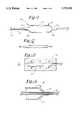
- FIG. 1is a side elevational view of the distal region of a balloon catheter
- FIGS. 2 and 3schematically illustrate fabrication of dilatation balloon of the catheter
- FIG. 4is an enlarged sectional elevation showing a distal portion of the dilatation balloon
- FIG. 5is a schematic view of an apparatus for further fabricating the dilatation balloon
- FIG. 6is a schematic view similar to the sectional view of FIG. 4, illustrating use of the apparatus to remove material from the dilatation balloon;
- FIG. 7is a sectional view similar to that in FIG. 4, showing the dilatation balloon after excimer laser ablation;
- FIG. 8is a schematic view of an alternative laser ablation apparatus
- FIGS. 9 and 10are schematic views of another alternative laser ablation apparatus
- FIGS. 11 and 12illustrate ablatively formed grooves in a dilatation balloon
- FIG. 13illustrates use of the apparatus of FIG. 5, after adjusting the laser beam approach angle, for removing material from a distal tip of a catheter;
- FIG. 14shows the catheter distal tip after ablation
- FIG. 15shows an alternative catheter distal tip after ablation.
- FIG. 1the distal end region of a balloon catheter 16.
- the balloon catheterincludes an elongate and pliable length of catheter tubing 18 constructed of a body compatible, polymeric material, preferably a polyester such as that sold under the brand name Hytrel. Other suitable materials include polyolefins, polyamides, thermal plastic polyurethanes, and copolymers of these materials.
- a dilatation balloon 20surrounds catheter tubing 18 along the distal end region. The dilatation balloon is shown in its fully expanded or dilated configuration, i.e. when the balloon contains a fluid under pressure. The fluid is supplied to the balloon interior through a balloon inflation lumen 22 open to the balloon interior and to the proximal end of catheter tubing 18.
- dilatation balloon 20When fully expanded, dilatation balloon 20 includes a main body or medial section 24, essentially an axially extended cylinder substantially concentric about the catheter tubing.
- the dilatation balloonhas a diameter much larger than the diameter of catheter tubing 18.
- the catheter tubing outside diametercan be about 0.04 inches (1 mm).
- the balloon diameter along medial working section 24typically is in the range of 3.0-4.0 mm, or in the range of 1.5-2.5 mm for treating obstructions in smaller vascular passageways.
- proximal tapered section or cone 26 and a distal tapered section or cone 28At opposite ends of the medial section are a proximal tapered section or cone 26 and a distal tapered section or cone 28.
- the proximal coneconverges in the direction away from the medial section toward an annular proximal mounting section or stem 30.
- the inner diameter of stem 30is substantially equal to the outer diameter of the catheter tubing, to provide an annular interface region along which the interior surface of stem 30 and the exterior
- distal cone 28converges in the distal direction from medial section 24 to a distal mounting section or stem 32.
- the inner diameter of the distal stemis essentially equal to the catheter outer diameter in the region of stem 32. Frequently the diameter of distal stem 32 is less than the inner diameter of proximal stem 30, because the catheter tubing 18 typically is narrower near the distal stem than it is near the proximal stem.
- Dilatation balloon 20is constructed of a polymeric material, preferably polyethylene terephthalate (PET). Other suitable materials include polyethylene and polyamide. Balloon 20 is sufficiently pliable to enable and facilitate its assumption of a delivery configuration in which the balloon is evacuated and is wrapped circumferentially about the catheter tubing. This reduces the transverse profile of the catheter and balloon, enabling delivery of the dilatation balloon within smaller vascular passageways.
- PETpolyethylene terephthalate
- Balloon 20is sufficiently pliable to enable and facilitate its assumption of a delivery configuration in which the balloon is evacuated and is wrapped circumferentially about the catheter tubing. This reduces the transverse profile of the catheter and balloon, enabling delivery of the dilatation balloon within smaller vascular passageways.
- balloon 20responsive to a fluid under pressure supplied through its interior, balloon 20 must readily assume the expanded configuration shown in FIG. 1. Because the PET or other balloon material is relatively inexpansible as well as pliable, balloon 20 tends to maintain the configuration shown in FIG. 1 under increased fluid pressure within the balloon, up to a burst pressure (much larger than pressures occurring during use) at which rupture occurs.
- FIGS. 2 and 3schematically illustrate fabrication of dilatation balloon 20.
- a length of PET tubing 34is subjected to an axial tensile force as indicated by the arrows, while being heated to a temperature above the second order transition temperature (e.g. 90° C.).
- Sufficient forceis applied to extend tubing 34 to at least three times its original length, to axially orient the tubing.
- the axially extended tubingis radially expanded within a form 36 having an internal profile for defining an expanded balloon shape. Expansion is accomplished by closing off one end of the tubing, then supplying a gas (e.g. nitrogen) under pressure to the tubing interior.
- a gase.g. nitrogen
- Dilatation balloon 20fabricated as described to this point, is shown partially (distal portion) in FIG. 4, it being understood that the proximal portion of the dilatation balloon exhibits similar profile and wall thickness characteristics.
- the dilatation balloonhas a wall thickness t 1 in the range of 0.0004-0.0008 inches (0.01-0.02 mm).
- the wall thicknessis substantially equal to t 1 near the medial section, then gradually increases to a thickness in the range of 0.001-0.0025 inches (0.025-0.062 mm) adjacent distal stem 32.
- the hoop strength of dilatation balloon 20is determined by the formula:
- ⁇is the hoop strength
- pis the pressure
- dis the dilatation balloon diameter
- tis the wall thickness.
- the maximum diameter dis along medial section 24. Accordingly, hoop strength is determined by wall thickness t 1 along the medial section. The excess wall thickness along tapered section 28 contributes nothing to the balloon hoop strength.
- the excess thicknessis a detriment for several reasons.
- the excess wall thicknessincreases stiffness at and near the junction.
- balloon catheter 16is less flexible and more difficult to maneuver through curved vascular passageways.
- the increased wall thicknessadds to the profile of the balloon.
- balloon 20is more difficult to flatten and wrap circumferentially about the catheter in the delivery configuration as discussed above. As a result, the profile of the wrapped balloon is larger than necessary, unduly limiting access to smaller vascular passageways.
- FIG. 5illustrates a device 38 for selectively removing polymeric material from balloon catheter 16, reducing its profile and stiffness in the region of the dilatation balloon, and thereby enhancing its maneuverability and utility in smaller, more tortuous body passageways.
- Device 38includes an elongate stainless steel mandrel 40.
- the outside diameter of the mandrelis approximately equal to the diameter of stems 30 and 32 of the dilatation balloon, to permit a slidable mounting of the balloon onto the mandrel.
- Mandrel 40is removably clamped within a jig 42 operable to rotate the mandrel about a longitudinal axis.
- Mandrel 40 at its opposite endis supported within a guide 44 for more stability in its rotation.
- An excimer laser 46 (ArF)is supported near mandrel 40 and generates an excimer laser beam 48 shaped by an optical assembly 50 including a converging lens for focusing beam 48 onto the exterior surface 52 of the dilatation balloon along tapered section 28.
- a mask 54is interposed between the laser and balloon surface 52 to more sharply define the area selected for treatment.
- Mandrel 40incorporates a lumen (not shown) for expanding dilatation balloon 20, so that the balloon when mounted on the mandrel assumes its expanded shape, with tapered sections 26 and 28 having truncated conical configurations.
- Excimer laser beam 48preferably is perpendicular to the dilatation balloon exterior surface along tapered section 28.
- the dilatation balloonrotates with mandrel 40.
- the laser, beam conditioning optics and maskare movable generally axially and radially, but more particularly parallel to the profile of tapered section 28 as indicated by the arrows in the figure.
- beam 48can be caused to impinge upon any selected portion of the balloon's exterior surface along the tapered section.
- dilatation balloon 20can be rotated in stepped fashion, timed in accordance with the pulses of excimer laser beam 48.
- polymeric materialcan be removed progressively, proceeding from a portion of the tapered section surface near the medial section 24 toward stem 32.
- a broken line at 56indicates the original tapered section profile.
- Material to be removedis indicated at 58, with the other material showing the desired profile of tapered section 22 following treatment, i.e. showing a substantially uniform wall thickness equal to thickness t 1 along the medial section. While this degree of material removal is preferred, it can be understood that any amount of material removal that substantially reduces the wall thickness gradient is beneficial.
- Excimer laser ablation of the polymeric materialforms a channel in the polymeric material, approximately equal in depth to the diameter of beam 48, which preferably is focused or nearly focused at the exterior surface.
- Rotation of balloon 20 and translation of the laser assemblycan be continuous or stepped. In either event, they occur in concert to ensure complete coverage of the area of intended material removal.
- This areacan be covered in a continuous sweep, i.e. in a close or tight helical pattern, alternatively, the area can be covered in a series of adjacent rings.
- materialmust be removed to a depth that increases progressively in the direction toward stem 32.
- the increased removalis achieved by increasing the number of incremental episodes (i.e. individual pulses) applied to the surface near the stem, rather than by increasing the pulse duration or pulse energy (i.e. fluence), which may introduce unwanted thermal effects.
- material removal during a given annular traverse or a single rotation of the ballooncan be increased by increasing pulse frequency.
- increasing the number of annular traverses of the balloonis the most effective manner of removing additional material without introducing thermal effects.
- Excimer laser ablationsometimes also called ablative photo decomposition, is believed to have photo-chemical and photo-thermal aspects.
- the photo-chemical aspectinvolves breaking chemical bonds to cause disassociation of molecules of the polymeric material subject to excimer laser energy.
- a highly localized and abrupt increase in pressureresults, tending to eject material from the exposed area.
- the ejected materialis heated, but rapidly removes heat from the treatment site by its ejection. Accordingly, any temperature increase at the treatment site is extremely brief, and little or no thermal effect results.
- photo-thermal effectswhich involve vibration of the polymeric molecules, become more apparent. While actual operating parameters can vary with the polymeric material and nature of material removal, the minimizing of thermal effects is important. Excessive concentrations of heat can cause crystallization or localized melting where the polymeric material may become brittle. In either event, catheter flexibility and maneuverability are adversely effected.
- decompositionis primarily photo-chemical and thinning of the catheter balloon walls does not materially reduce balloon and catheter flexibility.
- a suitable range for fluence levelis 100-800 mJ/cm 2 .
- a more preferred rangeis about 160-750 mJ/cm 2 , with a preference toward the lower end of this range to minimize thermal effects.
- a suitable pulse durationis 10-15 ns with a pulse frequency of about 10-50 pulses/second, and more preferably 10-40 pulses/second. Again, minimizing thermal effects favors the lower portion of the range.
- the preferred wavelength as notedis 193 nm (ArF laser), but absorption characteristics of a specific polymer may favor another wavelength, e.g. 248 nm (KrF laser) or 308 nm (XeCl laser), for a preferred range of about 190-310 nm.
- a stream or flow of gase.g. nitrogen
- gase.g. nitrogen
- the desired flowcan be generated with a source of nitrogen under pressure, as indicated at 60. As it exits source 60, the nitrogen undergoes a rapid decrease in pressure and cools, whereupon it tends to cool the ablation area, primarily by convection but also in carrying away heated ablated material.
- FIG. 7illustrates the portion of dilatation balloon 20 shown in FIG. 6 after excimer laser ablation, with all unwanted material removed.
- the thickness t2 of a dilatation balloon wall 62 along tapered section 28is substantially uniform, preferably varying by no more than about 10% or at most about 25%, and substantially equal to (e.g. within about 25% of, and more preferably within about 10% of) the thickness t 1 of the wall along medial section 24.
- balloon 20While only the distal portion of balloon 20 has been illustrated in detail, a substantially similar laser ablation is performed along proximal tapered section 26.
- the balloon wall thickness along both tapered sectionsis substantially reduced, especially near the stems.
- balloon 20is much flatter when evacuated and can be wrapped more tightly about catheter tubing 18 to present a smaller delivery profile.
- Balloon maneuverability and flexibilityare enhanced, due to the substantially reduced stiffness along the tapered sections. These improvements are achieved virtually without crystallization, embrittlement or other undesirable change in morphology.
- a favorable result of excimer laser treatmentis a change in wetting characteristics whereby the balloon is more hydrophilic in the treated area. This reduces any tendency to cause or promote clotting.
- FIG. 8illustrates and alternative apparatus 64 for excimer laser ablation of balloon 20.
- a stationary excimer laser source 66generates a beam 68 of the preferred wavelength of 193 nm. Beam 68 is directed through a diverging lens 70 and then through a collimating lens 72. The collimated beam is diverted by a series of planar reflectors 74, 76 and 78, and then through a focusing lens 80 which locates the beam focal point near exterior surface 52 of the dilatation balloon.
- Dilatation balloon 20is supported on an elongate stationary shaft 82 and remains stationary.
- the required relative movementis achieved by rotating beam 68, in particular by rotating planar reflectors 74-78 about an axis coincident with shaft 82.
- a sub-assembly including reflector 78 and lens 80further is pivotable to radially and axially displace the beam along tapered section 28.
- FIGS. 9 and 10illustrate a further alternative excimer laser ablation apparatus 83 including a laser source 84, an optical assembly 86 for shaping and focusing a laser beam 88 and a movable plate 90 for supporting dilatation balloon 20 in an evacuated, flat configuration.
- Stepper motors 92 and 93are provided for translating plate 90 in two perpendicular directions x and y (FIG. 10) that are horizontal, i.e. parallel to the major plane of the flattened balloon.
- the combined motion of plate 90creates the effect of a series of adjacent sweeps of beam 88 transversely across tapered sections 26 and 28. To substantially reduce or remove the thickness gradient, the number of sweeps is increased in the direction approaching the stems.
- dilatation balloon 20When all excess material has been removed from the exposed upper side, dilatation balloon 20 is turned over for removal of material from the opposite side to complete the process.
- a source of pressurized nitrogen for coolingcan be used if desired, as indicated at 94.
- the desired relative motioncan be achieved by translating the laser source and optics, thus to move the beam rather than the dilatation balloon.
- the primary advantage in using apparatus 83is that dilatation balloon 20 need not be expanded for removal of material.
- materialcan be selectively ablated to form an array of channels or grooves 96 in a balloon wall 97 along each of the tapered sections.
- the channelscan be uniform in width as shown, or may diverge in the direction toward medial section 24. In either event, the depth of each channel 96 increases in the direction toward the stem.
- Channels 96reduce the balloon profile and rigidity along the tapered sections, especially near the stems, and thus reduce the balloon profile, allow a tighter wrapping of the balloon for delivery and enhance catheter maneuverability.
- FIG. 13illustrates device 38 with a dilatation balloon 98 and a catheter 100 supported on rotatable mandrel 40.
- Excimer laser beam 48is directed onto a distal tip region 102 of the catheter, which extends beyond a stem 104 of the dilatation balloon.
- the beamis not perpendicular, but rather is directed onto the tip region at an acute angle with respect to the mandrel rotational axis.
- beam 48is not as sharply in focus at the exterior surface.
- the resultis a gradient in fluence along the surface of tip region 102 with the fluence level increasing in the distal direction.
- the resultis a tendency in the excimer laser pulses to remove polymeric material to depths that increase in the distal direction.
- the resultis a converging distal tip region, as shown in FIG. 14.
- Apparatus 64can be adjusted to achieve the same result, if it is desired to maintain the balloon stationary during ablation. As seen in FIG. 15, the technique can be used to remove dilatation balloon material in a catheter in which the catheter tubing 106 does not extend distally beyond a balloon stem 108. In both cases there is a reduction in tip profile and less stiffness at the distal tip, tending to enhance catheter maneuverability.
- controlled excimer laser ablationselectively thins the walls of dilatation balloons and catheters.
- the inventionenables fabrication of dilatation balloons according to a process that yields favorably high burst pressures, while eliminating or substantially reducing an undesirable gradient in wall thickness. The result is a dilatation balloon with the desired burst pressure but without the excess wall thickness, particularly along the tapered sections near the balloon stems.
- Co-extruded or multi-layered balloonsalthough not shown, can be fabricaed or treated according to this technique. While the preceding description features dilatation balloons and catheters, it is to be appreciated that the invention can apply to other balloons and catheters as well, e.g.
- catheters with balloons expandable to deploy prosthesesmore particularly to enlarge plastically deformable stents.
- Catheter balloons intended for use in body passages other than vascular passageslikewise are enhanced when fabricated or treated according to the invention. With appropriately thinned walls, the balloon and catheter facilitate tighter balloon wrapping for a reduced delivery profile, and exhibit greater flexibility for maneuvering in small and tortuous vascular passageways.
Landscapes
- Health & Medical Sciences (AREA)
- Heart & Thoracic Surgery (AREA)
- Life Sciences & Earth Sciences (AREA)
- Engineering & Computer Science (AREA)
- Hematology (AREA)
- Animal Behavior & Ethology (AREA)
- Biophysics (AREA)
- Pulmonology (AREA)
- Anesthesiology (AREA)
- Biomedical Technology (AREA)
- Veterinary Medicine (AREA)
- Child & Adolescent Psychology (AREA)
- General Health & Medical Sciences (AREA)
- Public Health (AREA)
- Manufacturing & Machinery (AREA)
- Vascular Medicine (AREA)
- Media Introduction/Drainage Providing Device (AREA)
- Materials For Medical Uses (AREA)
- Laser Surgery Devices (AREA)
- Surgical Instruments (AREA)
Abstract
Description
σ=pd/2t;
Claims (6)
Priority Applications (10)
| Application Number | Priority Date | Filing Date | Title |
|---|---|---|---|
| US08/582,371US5733301A (en) | 1996-01-11 | 1996-01-11 | Laser ablation of angioplasty catheters and balloons |
| EP96203423AEP0783897B1 (en) | 1996-01-11 | 1996-12-03 | Laser ablation of angioplasty catheters and balloons |
| AT96203423TATE270568T1 (en) | 1996-01-11 | 1996-12-03 | LASER ABLATION OF ANGIOPLASTY CATHETER AND BALLOON |
| DE69632855TDE69632855T2 (en) | 1996-01-11 | 1996-12-03 | Laser ablation of angioplasty catheters and balloons |
| CA002194734ACA2194734C (en) | 1996-01-11 | 1997-01-09 | Laser ablation of angioplasty catheters and balloons |
| JP9003066AJPH09192227A (en) | 1996-01-11 | 1997-01-10 | Catheter for forming blood vessel, and removing and shaping balloon using laser |
| AU10113/97AAU1011397A (en) | 1996-01-11 | 1997-01-10 | Laser ablation of angioplasty catheters and balloons |
| MX9700334AMX9700334A (en) | 1996-01-11 | 1997-01-10 | Laser ablation of angioplasty catheters and ballons. |
| US08/956,963US5826588A (en) | 1996-01-11 | 1997-10-23 | Laser ablation of angioplasty catheters and balloons |
| JP2007000214AJP4795976B2 (en) | 1996-01-11 | 2007-01-04 | Method for making a body-insertable and inflatable processing device |
Applications Claiming Priority (1)
| Application Number | Priority Date | Filing Date | Title |
|---|---|---|---|
| US08/582,371US5733301A (en) | 1996-01-11 | 1996-01-11 | Laser ablation of angioplasty catheters and balloons |
Related Child Applications (1)
| Application Number | Title | Priority Date | Filing Date |
|---|---|---|---|
| US08/956,963DivisionUS5826588A (en) | 1996-01-11 | 1997-10-23 | Laser ablation of angioplasty catheters and balloons |
Publications (1)
| Publication Number | Publication Date |
|---|---|
| US5733301Atrue US5733301A (en) | 1998-03-31 |
Family
ID=24328891
Family Applications (2)
| Application Number | Title | Priority Date | Filing Date |
|---|---|---|---|
| US08/582,371Expired - LifetimeUS5733301A (en) | 1996-01-11 | 1996-01-11 | Laser ablation of angioplasty catheters and balloons |
| US08/956,963Expired - LifetimeUS5826588A (en) | 1996-01-11 | 1997-10-23 | Laser ablation of angioplasty catheters and balloons |
Family Applications After (1)
| Application Number | Title | Priority Date | Filing Date |
|---|---|---|---|
| US08/956,963Expired - LifetimeUS5826588A (en) | 1996-01-11 | 1997-10-23 | Laser ablation of angioplasty catheters and balloons |
Country Status (8)
| Country | Link |
|---|---|
| US (2) | US5733301A (en) |
| EP (1) | EP0783897B1 (en) |
| JP (2) | JPH09192227A (en) |
| AT (1) | ATE270568T1 (en) |
| AU (1) | AU1011397A (en) |
| CA (1) | CA2194734C (en) |
| DE (1) | DE69632855T2 (en) |
| MX (1) | MX9700334A (en) |
Cited By (57)
| Publication number | Priority date | Publication date | Assignee | Title |
|---|---|---|---|---|
| US5826588A (en)* | 1996-01-11 | 1998-10-27 | Schneider (Usa) Inc. | Laser ablation of angioplasty catheters and balloons |
| US5948016A (en)* | 1997-09-25 | 1999-09-07 | Jang; G. David | Intravascular stent with non-parallel slots |
| US6024752A (en)* | 1998-05-11 | 2000-02-15 | Scimed Life Systems, Inc. | Soft flexible tipped balloon |
| US6129706A (en)* | 1998-12-10 | 2000-10-10 | Janacek; Jaroslav | Corrugated catheter balloon |
| US6193738B1 (en) | 1998-05-11 | 2001-02-27 | Scimed Life Systems, Inc. | Balloon cones and waists thinning methodology |
| US20020049493A1 (en)* | 1996-04-26 | 2002-04-25 | Jang G. David | Intravascular stent |
| US20020111620A1 (en)* | 2001-02-14 | 2002-08-15 | Broncus Technologies, Inc. | Devices and methods for maintaining collateral channels in tissue |
| US20020161429A1 (en)* | 1996-04-26 | 2002-10-31 | Jang G. David | Intravascular stent |
| US20020169500A1 (en)* | 1996-04-26 | 2002-11-14 | Jang G. David | Intravascular stent |
| US6492615B1 (en)* | 2000-10-12 | 2002-12-10 | Scimed Life Systems, Inc. | Laser polishing of medical devices |
| US20030078613A1 (en)* | 2001-10-24 | 2003-04-24 | Scimed Life Systems, Inc. | Distal balloon waist material relief and method of manufacture |
| US20030093144A1 (en)* | 1998-02-02 | 2003-05-15 | Scimed Life Systems, Inc. | Tubular stent consists of chevron-shape expansion struts and contralaterally attached diagonal-connectors |
| US20030139762A1 (en)* | 1999-12-22 | 2003-07-24 | Lee Jeong S. | Angioplasty balloon with thin-walled taper and method of making the same |
| US6638245B2 (en) | 2001-06-26 | 2003-10-28 | Concentric Medical, Inc. | Balloon catheter |
| US6702782B2 (en) | 2001-06-26 | 2004-03-09 | Concentric Medical, Inc. | Large lumen balloon catheter |
| US20040073250A1 (en)* | 2002-10-15 | 2004-04-15 | Pederson Gary John | Catheter balloon with advantageous cone design |
| US20040106985A1 (en)* | 1996-04-26 | 2004-06-03 | Jang G. David | Intravascular stent |
| US20040133271A1 (en)* | 2000-09-22 | 2004-07-08 | Jang G. David | Intravascular stent and assembly |
| US20040225318A1 (en)* | 2003-05-05 | 2004-11-11 | Tracee Eidenschink | Balloon catheter and method of making same |
| US20050056292A1 (en)* | 1999-08-05 | 2005-03-17 | Cooper Joel D. | Devices for maintaining patency of surgically created channels in tissue |
| US20050137619A1 (en)* | 2003-12-19 | 2005-06-23 | Scott Schewe | Molds and related methods and articles |
| US20060033240A1 (en)* | 2004-08-13 | 2006-02-16 | Jan Weber | Method and apparatus for forming a feature in a workpiece by laser ablation with a laser beam having an adjustable intensity profile to redistribute the energy density impinging on the workpiece |
| US20060116749A1 (en)* | 2003-07-18 | 2006-06-01 | Broncus Technologies, Inc. | Devices for maintaining patency of surgically created channels in tissue |
| US20060167407A1 (en)* | 2005-01-26 | 2006-07-27 | Jan Weber | Medical devices and methods of making the same |
| US20060182873A1 (en)* | 2005-02-17 | 2006-08-17 | Klisch Leo M | Medical devices |
| US20060184112A1 (en)* | 2005-02-17 | 2006-08-17 | Horn Daniel J | Medical devices |
| US7115183B2 (en) | 1997-10-15 | 2006-10-03 | Scimed Life Systems, Inc. | Catheter with spiral cut transition member |
| US20060276820A1 (en)* | 2003-05-19 | 2006-12-07 | Youichi Yamaguchi | Balloon catheter and method of manufacturing the same |
| US20070255304A1 (en)* | 2002-02-21 | 2007-11-01 | Roschak Edmund J | Devices for creating passages and sensing for blood vessels |
| US20080021386A1 (en)* | 2006-07-18 | 2008-01-24 | Nellcor Puritan Bennett Incorporated | Medical tube including an inflatable cuff having a notched collar |
| US20080086073A1 (en)* | 2006-10-10 | 2008-04-10 | Mcdaniel Benjamin | Multi-region staged inflation balloon |
| US20080132836A1 (en)* | 2006-11-03 | 2008-06-05 | Cook Incorporated | Balloon catheter having improved balloon folding capability |
| US20080157444A1 (en)* | 2006-12-11 | 2008-07-03 | Cook Incorporated | Method of making a fiber-reinforced medical balloon |
| US20090112300A1 (en)* | 2007-10-29 | 2009-04-30 | Horn-Wyffels Mitchell L | Reduced bending stiffness polyurethane tubing |
| US20100193483A1 (en)* | 2009-02-03 | 2010-08-05 | Abbott Cardiovascular Systems Inc. | Laser cutting process for forming stents |
| US20110227390A1 (en)* | 2010-03-17 | 2011-09-22 | Lear Corporation | Seat trim assembly |
| US20110284498A1 (en)* | 2005-06-17 | 2011-11-24 | Abbott Laboratories | Method of reducing rigidity of angioplasty balloon sections |
| WO2012071095A1 (en) | 2010-11-22 | 2012-05-31 | Cook Medical Technologies Llc | Scoring balloon and method of making same |
| US8197742B2 (en) | 2010-05-18 | 2012-06-12 | Cook Medical Technologies Llc | Laser ablation process for removing a portion of dilation element from a balloon |
| US8308682B2 (en) | 2003-07-18 | 2012-11-13 | Broncus Medical Inc. | Devices for maintaining patency of surgically created channels in tissue |
| US8608724B2 (en) | 2004-07-19 | 2013-12-17 | Broncus Medical Inc. | Devices for delivering substances through an extra-anatomic opening created in an airway |
| US8709034B2 (en) | 2011-05-13 | 2014-04-29 | Broncus Medical Inc. | Methods and devices for diagnosing, monitoring, or treating medical conditions through an opening through an airway wall |
| US8840743B2 (en)* | 2012-09-11 | 2014-09-23 | Abbott Cardiovascular Systems Inc. | Soft tip balloon catheter |
| US9320530B2 (en) | 2013-03-13 | 2016-04-26 | The Spectranetics Corporation | Assisted cutting balloon |
| US9345532B2 (en) | 2011-05-13 | 2016-05-24 | Broncus Medical Inc. | Methods and devices for ablation of tissue |
| US9539692B2 (en) | 2014-08-15 | 2017-01-10 | Covidien Lp | Material removal from balloon cone |
| US10201387B2 (en) | 2013-03-13 | 2019-02-12 | The Spectranetics Corporation | Laser-induced fluid filled balloon catheter |
| US10272260B2 (en) | 2011-11-23 | 2019-04-30 | Broncus Medical Inc. | Methods and devices for diagnosing, monitoring, or treating medical conditions through an opening through an airway wall |
| US10413702B2 (en) | 2011-10-21 | 2019-09-17 | Boston Scientific Scimed, Inc. | Locking catheter hub |
| CN110917472A (en)* | 2014-11-20 | 2020-03-27 | 爱德华兹生命科学公司 | Inflatable device with etched finish |
| US10696005B2 (en) | 2016-07-29 | 2020-06-30 | Freudenberg Medical, Inc. | Assembly and method of same for mechanically skiving to remove balloon parison tubing materials |
| US10842567B2 (en) | 2013-03-13 | 2020-11-24 | The Spectranetics Corporation | Laser-induced fluid filled balloon catheter |
| US10850078B2 (en) | 2014-12-30 | 2020-12-01 | The Spectranetics Corporation | Electrically-induced fluid filled balloon catheter |
| US10898213B2 (en) | 2014-12-30 | 2021-01-26 | The Spectranetics Corporation | Electrically-induced pressure wave emitting catheter sheath |
| US11058492B2 (en) | 2014-12-30 | 2021-07-13 | The Spectranetics Corporation | Laser-induced pressure wave emitting catheter sheath |
| US11246659B2 (en) | 2014-08-25 | 2022-02-15 | The Spectranetics Corporation | Liquid laser-induced pressure wave emitting catheter sheath |
| US12440654B2 (en) | 2022-02-25 | 2025-10-14 | Olympus Corporation | Balloon-equipped treatment tool for endoscope, and method of folding balloon-equipped treatment tool for endoscope |
Families Citing this family (59)
| Publication number | Priority date | Publication date | Assignee | Title |
|---|---|---|---|---|
| US6221467B1 (en) | 1997-06-03 | 2001-04-24 | Scimed Life Systems, Inc. | Coating gradient for lubricious coatings on balloon catheters |
| US6139525A (en)* | 1997-07-08 | 2000-10-31 | Advanced Cardiovascular Systems, Inc. | Fusion bonding of catheter components |
| DE69828429T2 (en)* | 1997-10-08 | 2005-12-08 | Kaneka Corp. | BALLOON CATHETER AND MANUFACTURING METHOD THEREFOR |
| US6165152A (en)* | 1998-09-11 | 2000-12-26 | Advanced Cardiovascular Systems, Inc. | Catheter with a flexible tip and taper and method of manufacture |
| US6613066B1 (en) | 1998-10-05 | 2003-09-02 | Kaneka Corporation | Balloon catheter and production method therefor |
| JP2000217924A (en)* | 1999-02-01 | 2000-08-08 | Kanegafuchi Chem Ind Co Ltd | Extended body for extended catheter and its manufacture |
| US6786889B1 (en) | 1999-03-31 | 2004-09-07 | Scimed Life Systems, Inc | Textured and/or marked balloon for stent delivery |
| US6258099B1 (en) | 1999-03-31 | 2001-07-10 | Scimed Life Systems, Inc. | Stent security balloon/balloon catheter |
| US6592550B1 (en) | 1999-09-17 | 2003-07-15 | Cook Incorporated | Medical device including improved expandable balloon |
| US6605031B1 (en) | 1999-09-22 | 2003-08-12 | Advanced Cardiovascular Systems, Inc. | Stepped centering balloon for optimal radiation delivery |
| US6582417B1 (en) | 1999-09-22 | 2003-06-24 | Advanced Cardiovascular Systems, Inc. | Methods and apparatuses for radiation treatment |
| US6471672B1 (en) | 1999-11-10 | 2002-10-29 | Scimed Life Systems | Selective high pressure dilation balloon |
| US6702802B1 (en) | 1999-11-10 | 2004-03-09 | Endovascular Technologies, Inc. | Catheters with improved transition |
| US6540734B1 (en) | 2000-02-16 | 2003-04-01 | Advanced Cardiovascular Systems, Inc. | Multi-lumen extrusion tubing |
| US7994449B2 (en)* | 2000-02-16 | 2011-08-09 | Advanced Cardiovascular Systems, Inc. | Square-wave laser bonding |
| US6562061B1 (en) | 2000-02-22 | 2003-05-13 | Scimed Life Systems, Inc. | Stent delivery balloon with securement structure |
| US6881209B2 (en) | 2000-05-25 | 2005-04-19 | Cook Incorporated | Medical device including unitary, continuous portion of varying durometer |
| US6652485B1 (en) | 2000-05-31 | 2003-11-25 | Advanced Cardiovascular Systems, Inc. | Balloon shoulder designs |
| US6488654B2 (en)* | 2000-12-12 | 2002-12-03 | Advanced Cardiovascular Systems, Inc. | Method of removing material from a polymer tube or catheter balloon shaft |
| JP4704581B2 (en)* | 2001-02-22 | 2011-06-15 | テルモ株式会社 | Balloon catheter and balloon catheter manufacturing method |
| JP4782297B2 (en)* | 2001-03-09 | 2011-09-28 | 川澄化学工業株式会社 | Catheter balloon and balloon catheter |
| WO2002083391A1 (en)* | 2001-04-12 | 2002-10-24 | Sodripack Nv | Method and device for reducing the adhesion trend of newly produced moulded polymer bodies in a defined manner |
| US6786886B2 (en) | 2001-08-03 | 2004-09-07 | Scimed Life Systems, Inc. | Method for stabilizing balloon during dilation |
| JP4955162B2 (en)* | 2001-08-28 | 2012-06-20 | テルモ株式会社 | Balloon for living organ dilator and living organ dilator |
| US6764709B2 (en)* | 2001-11-08 | 2004-07-20 | Scimed Life Systems, Inc. | Method for making and measuring a coating on the surface of a medical device using an ultraviolet laser |
| DE50112453D1 (en)* | 2001-11-28 | 2007-06-14 | Abbott Lab Vascular Entpr Ltd | Catheter balloon |
| US20040127932A1 (en)* | 2002-09-12 | 2004-07-01 | Shah Tilak M. | Dip-molded polymeric medical devices with reverse thickness gradient, and method of making same |
| JP2004148013A (en)* | 2002-10-31 | 2004-05-27 | Kanegafuchi Chem Ind Co Ltd | Balloon, and balloon catheter |
| WO2004091471A2 (en) | 2003-04-04 | 2004-10-28 | Berger, Constance, F. | Apparatus for heating bottles and method of manufacturing same |
| DE10328817A1 (en)* | 2003-06-21 | 2005-01-13 | Biotronik Meß- und Therapiegeräte GmbH & Co. Ingenieurbüro Berlin | balloon catheter |
| JP4369700B2 (en)* | 2003-07-22 | 2009-11-25 | 川澄化学工業株式会社 | Catheter balloon and balloon catheter |
| DE10356518A1 (en)* | 2003-12-03 | 2005-07-28 | B. Braun Melsungen Ag | balloon catheter |
| US7264458B2 (en)* | 2004-01-07 | 2007-09-04 | Boston Scientific Scimed, Inc. | Process and apparatus for forming medical device balloons |
| US8070718B2 (en) | 2004-12-13 | 2011-12-06 | Boston Scientific Scimed, Inc. | Medical devices formed with a sacrificial structure and processes of forming the same |
| US8550985B2 (en)* | 2004-12-14 | 2013-10-08 | Boston Scientific Scimed, Inc. | Applications of LIPSS in polymer medical devices |
| US20060224115A1 (en)* | 2005-03-30 | 2006-10-05 | Boston Scientific Scimed, Inc. | Balloon catheter with expandable wire lumen |
| US7691082B2 (en)* | 2005-07-01 | 2010-04-06 | Boston Scientific Scimed, Inc. | Medical devices |
| US7927362B2 (en) | 2005-07-21 | 2011-04-19 | Boston Scientific Scimed, Inc. | Laser ablated elastomer sheath profiles to enables stent securement |
| US8876763B2 (en) | 2005-11-01 | 2014-11-04 | Boston Scientific Scimed, Inc. | Composite balloon |
| US8226637B2 (en) | 2005-11-01 | 2012-07-24 | Japan Electel, Inc. | Balloon catheter system |
| US20070205539A1 (en)* | 2006-03-03 | 2007-09-06 | Boston Scientific Scimed, Inc. | Balloon mold design |
| US8216267B2 (en) | 2006-09-12 | 2012-07-10 | Boston Scientific Scimed, Inc. | Multilayer balloon for bifurcated stent delivery and methods of making and using the same |
| US8845581B2 (en)* | 2006-11-14 | 2014-09-30 | Boston Scientific Scimed, Inc. | Medical balloon deflation |
| US20080275426A1 (en)* | 2007-05-03 | 2008-11-06 | Boston Scientific Scimed, Inc. | Flexible and Durable Tip |
| US7985941B2 (en) | 2007-11-16 | 2011-07-26 | 3M Innovative Properties Company | Seamless laser ablated roll tooling |
| DE102008040914A1 (en) | 2008-08-01 | 2010-02-04 | Biotronik Vi Patent Ag | Balloon catheter and process for its preparation |
| WO2010019481A1 (en) | 2008-08-11 | 2010-02-18 | Conceptx Medical, Inc. | Systems and methods for treating dyspnea, including via electrical afferent signal blocking |
| WO2011105267A1 (en)* | 2010-02-25 | 2011-09-01 | テルモ株式会社 | Balloon manufacturing method |
| US8597012B2 (en) | 2010-05-11 | 2013-12-03 | Polyzen, Inc. | Air disengagement assembly and method for manufacturing dip-molded articles out of RTV silicone by fully automated process |
| EP2574269B1 (en) | 2010-11-25 | 2016-08-31 | Olympus Corporation | Insertion portion rigidity changeable catheter with balloon |
| DE112011104637T5 (en)* | 2010-12-28 | 2015-10-22 | Cibiem, Inc.(n.d.Ges.d.Staates Delaware) | Method for restoring the autonomic balance of a patient |
| DE102012102620A1 (en)* | 2012-03-27 | 2013-10-02 | Acandis Gmbh & Co. Kg | Medical expansion element, method for producing such an expansion element and occlusion catheter with such an expansion element |
| WO2013163322A1 (en) | 2012-04-24 | 2013-10-31 | Cibiem, Inc. | Endovascular catheters and methods for carotid body ablation |
| WO2013181660A1 (en) | 2012-06-01 | 2013-12-05 | Cibiem, Inc. | Methods and devices for cryogenic carotid body ablation |
| FR3001912B1 (en)* | 2013-02-14 | 2015-02-27 | Sidel Participations | "PROCESS FOR OBTAINING A RECIPIENT MARK HAVING A STEP FOR MARKING A PREFORM" |
| EP3116408B1 (en) | 2014-03-12 | 2018-12-19 | Cibiem, Inc. | Ultrasound ablation catheter |
| US10201683B2 (en) | 2014-06-17 | 2019-02-12 | Covidien Lp | Medical balloon including pleats |
| JP2018171389A (en)* | 2017-03-31 | 2018-11-08 | 日本ゼオン株式会社 | Balloon catheter |
| WO2021053714A1 (en)* | 2019-09-17 | 2021-03-25 | オリンパス株式会社 | Balloon treatment tool for endoscope |
Citations (11)
| Publication number | Priority date | Publication date | Assignee | Title |
|---|---|---|---|---|
| US3733309A (en)* | 1970-11-30 | 1973-05-15 | Du Pont | Biaxially oriented poly(ethylene terephthalate)bottle |
| US4456000A (en)* | 1981-08-17 | 1984-06-26 | Angiomedics Corporation | Expandable occlusion apparatus |
| US4490421A (en)* | 1983-07-05 | 1984-12-25 | E. I. Du Pont De Nemours And Company | Balloon and manufacture thereof |
| US4906244A (en)* | 1988-10-04 | 1990-03-06 | Cordis Corporation | Balloons for medical devices and fabrication thereof |
| US4941877A (en)* | 1989-01-26 | 1990-07-17 | Cordis Corporation | Balloon catheter |
| US4963313A (en)* | 1987-11-30 | 1990-10-16 | Boston Scientific Corporation | Balloon catheter |
| US4964853A (en)* | 1987-02-27 | 1990-10-23 | Terumo Kabushiki Kaisha | Catheter equipped with expansible member |
| USRE33561E (en)* | 1983-07-05 | 1991-03-26 | E. I. Du Pont De Nemours And Company | Balloon and manufacture thereof |
| US5267959A (en)* | 1991-11-29 | 1993-12-07 | Schneider, Inc. | Laser bonding of angioplasty balloon catheters |
| US5334146A (en)* | 1990-11-10 | 1994-08-02 | Terumo Kabushiki Kaisha | Catheter balloon having varying wall thickness |
| US5358486A (en)* | 1987-01-09 | 1994-10-25 | C. R. Bard, Inc. | Multiple layer high strength balloon for dilatation catheter |
Family Cites Families (14)
| Publication number | Priority date | Publication date | Assignee | Title |
|---|---|---|---|---|
| EP0274411A3 (en)* | 1987-01-09 | 1988-11-30 | C.R. Bard, Inc. | Thin wall high strength balloon and method of manufacture |
| US4820349A (en)* | 1987-08-21 | 1989-04-11 | C. R. Bard, Inc. | Dilatation catheter with collapsible outer diameter |
| US5087244A (en)* | 1989-01-31 | 1992-02-11 | C. R. Bard, Inc. | Catheter and method for locally applying medication to the wall of a blood vessel or other body lumen |
| AU7524391A (en)* | 1990-05-15 | 1991-11-21 | C.R. Bard Inc. | Multiple layer high strength balloon for dilatation catheter |
| JP2791226B2 (en)* | 1991-03-08 | 1998-08-27 | キヤノン株式会社 | Method of manufacturing recording head and recording head |
| US5254091A (en)* | 1991-01-08 | 1993-10-19 | Applied Medical Resources Corporation | Low profile balloon catheter and method for making same |
| JP3057206B2 (en)* | 1991-03-27 | 2000-06-26 | キヤノン株式会社 | Electrical connection member and method of manufacturing the same |
| CA2071353C (en)* | 1991-12-10 | 1998-10-06 | Amy M. Wendell | Microbore catheter with side port(s) |
| US5525388A (en)* | 1992-08-07 | 1996-06-11 | Advanced Cardiovascular Systems, Inc. | Dilatation balloon with constant wall thickness |
| JP3694524B2 (en)* | 1993-08-23 | 2005-09-14 | ボストン サイエンティフィック コーポレイション | Improved balloon catheter |
| JPH07156569A (en)* | 1993-12-10 | 1995-06-20 | Ricoh Co Ltd | Mask for cream solder and manufacturing method thereof |
| JPH07265437A (en)* | 1994-03-30 | 1995-10-17 | Nippon Zeon Co Ltd | Balloon catheter for body cavity expansion |
| JPH07308383A (en)* | 1994-05-19 | 1995-11-28 | Nippon Zeon Co Ltd | catheter |
| US5733301A (en)* | 1996-01-11 | 1998-03-31 | Schneider (Usa) Inc. | Laser ablation of angioplasty catheters and balloons |
- 1996
- 1996-01-11USUS08/582,371patent/US5733301A/ennot_activeExpired - Lifetime
- 1996-12-03EPEP96203423Apatent/EP0783897B1/ennot_activeExpired - Lifetime
- 1996-12-03DEDE69632855Tpatent/DE69632855T2/ennot_activeExpired - Lifetime
- 1996-12-03ATAT96203423Tpatent/ATE270568T1/ennot_activeIP Right Cessation
- 1997
- 1997-01-09CACA002194734Apatent/CA2194734C/ennot_activeExpired - Fee Related
- 1997-01-10JPJP9003066Apatent/JPH09192227A/enactivePending
- 1997-01-10AUAU10113/97Apatent/AU1011397A/ennot_activeAbandoned
- 1997-01-10MXMX9700334Apatent/MX9700334A/enunknown
- 1997-10-23USUS08/956,963patent/US5826588A/ennot_activeExpired - Lifetime
- 2007
- 2007-01-04JPJP2007000214Apatent/JP4795976B2/ennot_activeExpired - Lifetime
Patent Citations (12)
| Publication number | Priority date | Publication date | Assignee | Title |
|---|---|---|---|---|
| US3733309A (en)* | 1970-11-30 | 1973-05-15 | Du Pont | Biaxially oriented poly(ethylene terephthalate)bottle |
| US3733309B1 (en)* | 1970-11-30 | 1985-09-03 | ||
| US4456000A (en)* | 1981-08-17 | 1984-06-26 | Angiomedics Corporation | Expandable occlusion apparatus |
| US4490421A (en)* | 1983-07-05 | 1984-12-25 | E. I. Du Pont De Nemours And Company | Balloon and manufacture thereof |
| USRE33561E (en)* | 1983-07-05 | 1991-03-26 | E. I. Du Pont De Nemours And Company | Balloon and manufacture thereof |
| US5358486A (en)* | 1987-01-09 | 1994-10-25 | C. R. Bard, Inc. | Multiple layer high strength balloon for dilatation catheter |
| US4964853A (en)* | 1987-02-27 | 1990-10-23 | Terumo Kabushiki Kaisha | Catheter equipped with expansible member |
| US4963313A (en)* | 1987-11-30 | 1990-10-16 | Boston Scientific Corporation | Balloon catheter |
| US4906244A (en)* | 1988-10-04 | 1990-03-06 | Cordis Corporation | Balloons for medical devices and fabrication thereof |
| US4941877A (en)* | 1989-01-26 | 1990-07-17 | Cordis Corporation | Balloon catheter |
| US5334146A (en)* | 1990-11-10 | 1994-08-02 | Terumo Kabushiki Kaisha | Catheter balloon having varying wall thickness |
| US5267959A (en)* | 1991-11-29 | 1993-12-07 | Schneider, Inc. | Laser bonding of angioplasty balloon catheters |
Non-Patent Citations (8)
| Title |
|---|
| "Excimer Laser Micromachining and Surface Microstructure Modification of Polymer Films", by P.E. Dyer, et al, Nov. 1-Nov. 13. |
| "Self-developing photoetching of poly(ethylene terephthalate) films by far-ultraviolet excimer laser tradition" by R. Srinivasan, et al, Appl. Phys. Lett. 41(6), Sep. 15, 1982, pp. 576-578. |
| "Ultraviolet Laesr Ablation of Organic Polymer Films", by R. Srinivasan, et al (1984). |
| "X-ray photoelectron spectroscopy studies on polymer surfaces after KrF laser ablation" by Kokai, et al, SPIE vol. 1190 Laser/Optical Processing of Electronic Materials (1989), pp. 95-103. |
| Excimer Laser Micromachining and Surface Microstructure Modification of Polymer Films , by P.E. Dyer, et al, Nov. 1 Nov. 13.* |
| Self developing photoetching of poly(ethylene terephthalate) films by far ultraviolet excimer laser tradition by R. Srinivasan, et al, Appl. Phys. Lett. 41(6), Sep. 15, 1982, pp. 576 578.* |
| Ultraviolet Laesr Ablation of Organic Polymer Films , by R. Srinivasan, et al (1984).* |
| X ray photoelectron spectroscopy studies on polymer surfaces after KrF laser ablation by Kokai, et al, SPIE vol. 1190 Laser/Optical Processing of Electronic Materials (1989), pp. 95 103.* |
Cited By (119)
| Publication number | Priority date | Publication date | Assignee | Title |
|---|---|---|---|---|
| US5826588A (en)* | 1996-01-11 | 1998-10-27 | Schneider (Usa) Inc. | Laser ablation of angioplasty catheters and balloons |
| US20020169500A1 (en)* | 1996-04-26 | 2002-11-14 | Jang G. David | Intravascular stent |
| US20020161429A1 (en)* | 1996-04-26 | 2002-10-31 | Jang G. David | Intravascular stent |
| US7081130B2 (en) | 1996-04-26 | 2006-07-25 | Boston Scientific Scimed, Inc. | Intravascular Stent |
| US7326241B2 (en) | 1996-04-26 | 2008-02-05 | Boston Scientific Scimed, Inc. | Intravascular stent |
| US20020049493A1 (en)* | 1996-04-26 | 2002-04-25 | Jang G. David | Intravascular stent |
| US20020062149A1 (en)* | 1996-04-26 | 2002-05-23 | Jang G. David | Intravascular stent |
| US9445926B2 (en) | 1996-04-26 | 2016-09-20 | Boston Scientific Scimed, Inc. | Intravascular stent |
| US20080300674A1 (en)* | 1996-04-26 | 2008-12-04 | Boston Scientific Scimed, Inc. | Intravascular Stent |
| US20040106985A1 (en)* | 1996-04-26 | 2004-06-03 | Jang G. David | Intravascular stent |
| US20020161430A1 (en)* | 1996-04-26 | 2002-10-31 | Jang G. David | Intravascular stent |
| US8021414B2 (en) | 1996-04-26 | 2011-09-20 | Boston Scientific Scimed, Inc. | Intravascular stent |
| US20020193870A1 (en)* | 1996-04-26 | 2002-12-19 | Jang G. David | Intravascular stent |
| US9078778B2 (en) | 1996-04-26 | 2015-07-14 | Boston Scientific Scimed, Inc. | Intravascular stent |
| US5948016A (en)* | 1997-09-25 | 1999-09-07 | Jang; G. David | Intravascular stent with non-parallel slots |
| US20070005009A1 (en)* | 1997-10-15 | 2007-01-04 | Scimed Life Systems, Inc. | Catheter with spiral cut transition member |
| US7115183B2 (en) | 1997-10-15 | 2006-10-03 | Scimed Life Systems, Inc. | Catheter with spiral cut transition member |
| US8206372B2 (en) | 1997-10-15 | 2012-06-26 | Boston Scientific Scimed, Inc. | Catheter with spiral cut transition member |
| US7744586B2 (en) | 1997-10-15 | 2010-06-29 | Boston Scientific Scimed, Inc. | Catheter with spiral cut transition member |
| US20030093144A1 (en)* | 1998-02-02 | 2003-05-15 | Scimed Life Systems, Inc. | Tubular stent consists of chevron-shape expansion struts and contralaterally attached diagonal-connectors |
| US8562665B2 (en) | 1998-02-02 | 2013-10-22 | Boston Scientific Scimed, Inc. | Tubular stent consists of chevron-shape expansion struts and contralaterally attached diagonal-connectors |
| US8357177B2 (en) | 1998-05-11 | 2013-01-22 | Boston Scientific Scimed, Inc. | Balloon cones and waists thinning methodology |
| US7771450B2 (en)* | 1998-05-11 | 2010-08-10 | Boston Scientific Scimed, Inc. | Balloon cones and waists thinning methodology |
| US20100320169A1 (en)* | 1998-05-11 | 2010-12-23 | Boston Scientific Scimed, Inc. | Balloon Cones and Waists Thinning Methodology |
| US6193738B1 (en) | 1998-05-11 | 2001-02-27 | Scimed Life Systems, Inc. | Balloon cones and waists thinning methodology |
| US20070213762A1 (en)* | 1998-05-11 | 2007-09-13 | Boston Scientific Scimed, Inc. | Balloon Cones and Waists Thinning Methodology |
| US7217278B2 (en)* | 1998-05-11 | 2007-05-15 | Boston Scientific Scimed, Inc. | Balloon cones and waists thinning methodology |
| US6024752A (en)* | 1998-05-11 | 2000-02-15 | Scimed Life Systems, Inc. | Soft flexible tipped balloon |
| US6129706A (en)* | 1998-12-10 | 2000-10-10 | Janacek; Jaroslav | Corrugated catheter balloon |
| US7815590B2 (en) | 1999-08-05 | 2010-10-19 | Broncus Technologies, Inc. | Devices for maintaining patency of surgically created channels in tissue |
| US20050056292A1 (en)* | 1999-08-05 | 2005-03-17 | Cooper Joel D. | Devices for maintaining patency of surgically created channels in tissue |
| US20100116279A9 (en)* | 1999-08-05 | 2010-05-13 | Cooper Joel D | Devices for maintaining patency of surgically created channels in tissue |
| EP1226016A4 (en)* | 1999-09-22 | 2006-04-19 | Boston Scient Ltd | METHOD OF WALL THICKENER REDUCTION OF CONVEYING REGIONS AND CURVED REGIONS OF A BALLOON CATHETER BALLOON |
| US20030139762A1 (en)* | 1999-12-22 | 2003-07-24 | Lee Jeong S. | Angioplasty balloon with thin-walled taper and method of making the same |
| US7766956B2 (en) | 2000-09-22 | 2010-08-03 | Boston Scientific Scimed, Inc. | Intravascular stent and assembly |
| US20040133271A1 (en)* | 2000-09-22 | 2004-07-08 | Jang G. David | Intravascular stent and assembly |
| US6492615B1 (en)* | 2000-10-12 | 2002-12-10 | Scimed Life Systems, Inc. | Laser polishing of medical devices |
| US7175644B2 (en)* | 2001-02-14 | 2007-02-13 | Broncus Technologies, Inc. | Devices and methods for maintaining collateral channels in tissue |
| US20070123922A1 (en)* | 2001-02-14 | 2007-05-31 | Broncus Technologies, Inc. | Devices and methods for maintaining collateral channels in tissue |
| US20020111620A1 (en)* | 2001-02-14 | 2002-08-15 | Broncus Technologies, Inc. | Devices and methods for maintaining collateral channels in tissue |
| US20110172699A1 (en)* | 2001-06-26 | 2011-07-14 | Concentric Medical, Inc. | Balloon Catheter |
| US20040079429A1 (en)* | 2001-06-26 | 2004-04-29 | Concentric Medical, Inc. | Balloon catherer |
| US7766049B2 (en) | 2001-06-26 | 2010-08-03 | Concentric Medical, Inc. | Balloon catheter |
| US6702782B2 (en) | 2001-06-26 | 2004-03-09 | Concentric Medical, Inc. | Large lumen balloon catheter |
| US6638245B2 (en) | 2001-06-26 | 2003-10-28 | Concentric Medical, Inc. | Balloon catheter |
| US7201763B2 (en) | 2001-10-24 | 2007-04-10 | Boston Scientific Scimed, Inc. | Distal balloon waist material relief and method of manufacture |
| US20030078613A1 (en)* | 2001-10-24 | 2003-04-24 | Scimed Life Systems, Inc. | Distal balloon waist material relief and method of manufacture |
| US20070255304A1 (en)* | 2002-02-21 | 2007-11-01 | Roschak Edmund J | Devices for creating passages and sensing for blood vessels |
| US20040073250A1 (en)* | 2002-10-15 | 2004-04-15 | Pederson Gary John | Catheter balloon with advantageous cone design |
| WO2004035127A1 (en) | 2002-10-15 | 2004-04-29 | Scimed Life Systems, Inc. | Catheter balloon with advantageous cone design |
| US7226472B2 (en) | 2002-10-15 | 2007-06-05 | Boston Scientific Scimed, Inc. | Catheter balloon with advantageous cone design |
| US20050203563A9 (en)* | 2002-10-15 | 2005-09-15 | Pederson Gary J.Jr. | Catheter balloon with advantageous cone design |
| US20040225318A1 (en)* | 2003-05-05 | 2004-11-11 | Tracee Eidenschink | Balloon catheter and method of making same |
| US7306616B2 (en) | 2003-05-05 | 2007-12-11 | Boston Scientific Scimed, Inc. | Balloon catheter and method of making same |
| US20060276820A1 (en)* | 2003-05-19 | 2006-12-07 | Youichi Yamaguchi | Balloon catheter and method of manufacturing the same |
| US8308682B2 (en) | 2003-07-18 | 2012-11-13 | Broncus Medical Inc. | Devices for maintaining patency of surgically created channels in tissue |
| US8002740B2 (en) | 2003-07-18 | 2011-08-23 | Broncus Technologies, Inc. | Devices for maintaining patency of surgically created channels in tissue |
| US20060116749A1 (en)* | 2003-07-18 | 2006-06-01 | Broncus Technologies, Inc. | Devices for maintaining patency of surgically created channels in tissue |
| US9533128B2 (en) | 2003-07-18 | 2017-01-03 | Broncus Medical Inc. | Devices for maintaining patency of surgically created channels in tissue |
| US20070267780A1 (en)* | 2003-12-19 | 2007-11-22 | Boston Scientific Scimed, Inc. | Molds and related methods and articles |
| US20050137619A1 (en)* | 2003-12-19 | 2005-06-23 | Scott Schewe | Molds and related methods and articles |
| US7985063B2 (en) | 2003-12-19 | 2011-07-26 | Boston Scientific Scimed, Inc. | Molds and related methods and articles |
| US10369339B2 (en) | 2004-07-19 | 2019-08-06 | Broncus Medical Inc. | Devices for delivering substances through an extra-anatomic opening created in an airway |
| US8784400B2 (en) | 2004-07-19 | 2014-07-22 | Broncus Medical Inc. | Devices for delivering substances through an extra-anatomic opening created in an airway |
| US11357960B2 (en) | 2004-07-19 | 2022-06-14 | Broncus Medical Inc. | Devices for delivering substances through an extra-anatomic opening created in an airway |
| US8608724B2 (en) | 2004-07-19 | 2013-12-17 | Broncus Medical Inc. | Devices for delivering substances through an extra-anatomic opening created in an airway |
| US8158904B2 (en) | 2004-08-13 | 2012-04-17 | Boston Scientific Scimed, Inc. | Method and apparatus for forming a feature in a workpiece by laser ablation with a laser beam having an adjustable intensity profile to redistribute the energy density impinging on the workpiece |
| US20060033240A1 (en)* | 2004-08-13 | 2006-02-16 | Jan Weber | Method and apparatus for forming a feature in a workpiece by laser ablation with a laser beam having an adjustable intensity profile to redistribute the energy density impinging on the workpiece |
| US8202245B2 (en) | 2005-01-26 | 2012-06-19 | Boston Scientific Scimed, Inc. | Medical devices and methods of making the same |
| US20060167407A1 (en)* | 2005-01-26 | 2006-07-27 | Jan Weber | Medical devices and methods of making the same |
| US8048028B2 (en)* | 2005-02-17 | 2011-11-01 | Boston Scientific Scimed, Inc. | Reinforced medical balloon |
| US8852146B2 (en) | 2005-02-17 | 2014-10-07 | Boston Scientific Scimed, Inc. | Reinforced medical balloon |
| US20060182873A1 (en)* | 2005-02-17 | 2006-08-17 | Klisch Leo M | Medical devices |
| US20060184112A1 (en)* | 2005-02-17 | 2006-08-17 | Horn Daniel J | Medical devices |
| US8292913B2 (en)* | 2005-06-17 | 2012-10-23 | Abbott Laboratories | Method of reducing rigidity of angioplasty balloon sections |
| US20110284498A1 (en)* | 2005-06-17 | 2011-11-24 | Abbott Laboratories | Method of reducing rigidity of angioplasty balloon sections |
| US8986339B2 (en) | 2005-06-17 | 2015-03-24 | Abbott Laboratories | Method of reducing rigidity of angioplasty balloon sections |
| US20100088876A1 (en)* | 2006-07-18 | 2010-04-15 | Nellcor Puritan Bennett Incorporated | Medical Tube Including an Inflatable Cuff Having a Notched Collar |
| US7654264B2 (en) | 2006-07-18 | 2010-02-02 | Nellcor Puritan Bennett Llc | Medical tube including an inflatable cuff having a notched collar |
| US20080021386A1 (en)* | 2006-07-18 | 2008-01-24 | Nellcor Puritan Bennett Incorporated | Medical tube including an inflatable cuff having a notched collar |
| US8096299B2 (en) | 2006-07-18 | 2012-01-17 | Nellcor Puritan Bennett Llc | Medical tube including an inflatable cuff having a notched collar |
| US9913969B2 (en) | 2006-10-05 | 2018-03-13 | Broncus Medical Inc. | Devices for delivering substances through an extra-anatomic opening created in an airway |
| US20080086073A1 (en)* | 2006-10-10 | 2008-04-10 | Mcdaniel Benjamin | Multi-region staged inflation balloon |
| US8728073B2 (en)* | 2006-10-10 | 2014-05-20 | Biosense Webster, Inc. | Multi-region staged inflation balloon |
| US20080132836A1 (en)* | 2006-11-03 | 2008-06-05 | Cook Incorporated | Balloon catheter having improved balloon folding capability |
| US7857786B2 (en) | 2006-11-03 | 2010-12-28 | Cook Incorporated | Balloon catheter having improved balloon folding capability |
| US7641844B2 (en)* | 2006-12-11 | 2010-01-05 | Cook Incorporated | Method of making a fiber-reinforced medical balloon |
| US20080157444A1 (en)* | 2006-12-11 | 2008-07-03 | Cook Incorporated | Method of making a fiber-reinforced medical balloon |
| US20090112300A1 (en)* | 2007-10-29 | 2009-04-30 | Horn-Wyffels Mitchell L | Reduced bending stiffness polyurethane tubing |
| US8872062B2 (en)* | 2009-02-03 | 2014-10-28 | Abbott Cardiovascular Systems Inc. | Laser cutting process for forming stents |
| US20100193483A1 (en)* | 2009-02-03 | 2010-08-05 | Abbott Cardiovascular Systems Inc. | Laser cutting process for forming stents |
| US20110227390A1 (en)* | 2010-03-17 | 2011-09-22 | Lear Corporation | Seat trim assembly |
| US8197742B2 (en) | 2010-05-18 | 2012-06-12 | Cook Medical Technologies Llc | Laser ablation process for removing a portion of dilation element from a balloon |
| WO2012071095A1 (en) | 2010-11-22 | 2012-05-31 | Cook Medical Technologies Llc | Scoring balloon and method of making same |
| US9421070B2 (en) | 2011-05-13 | 2016-08-23 | Broncus Medical Inc. | Methods and devices for diagnosing, monitoring, or treating medical conditions through an opening through an airway wall |
| US12016640B2 (en) | 2011-05-13 | 2024-06-25 | Broncus Medical Inc. | Methods and devices for diagnosing, monitoring, or treating medical conditions through an opening through an airway wall |
| US9486229B2 (en) | 2011-05-13 | 2016-11-08 | Broncus Medical Inc. | Methods and devices for excision of tissue |
| US8709034B2 (en) | 2011-05-13 | 2014-04-29 | Broncus Medical Inc. | Methods and devices for diagnosing, monitoring, or treating medical conditions through an opening through an airway wall |
| US10631938B2 (en) | 2011-05-13 | 2020-04-28 | Broncus Medical Inc. | Methods and devices for diagnosing, monitoring, or treating medical conditions through an opening through an airway wall |
| US8932316B2 (en) | 2011-05-13 | 2015-01-13 | Broncus Medical Inc. | Methods and devices for diagnosing, monitoring, or treating medical conditions through an opening through an airway wall |
| US9993306B2 (en) | 2011-05-13 | 2018-06-12 | Broncus Medical Inc. | Methods and devices for diagnosing, monitoring, or treating medical conditions through an opening through an airway wall |
| US9345532B2 (en) | 2011-05-13 | 2016-05-24 | Broncus Medical Inc. | Methods and devices for ablation of tissue |
| US10413702B2 (en) | 2011-10-21 | 2019-09-17 | Boston Scientific Scimed, Inc. | Locking catheter hub |
| US10272260B2 (en) | 2011-11-23 | 2019-04-30 | Broncus Medical Inc. | Methods and devices for diagnosing, monitoring, or treating medical conditions through an opening through an airway wall |
| US8840743B2 (en)* | 2012-09-11 | 2014-09-23 | Abbott Cardiovascular Systems Inc. | Soft tip balloon catheter |
| US10201387B2 (en) | 2013-03-13 | 2019-02-12 | The Spectranetics Corporation | Laser-induced fluid filled balloon catheter |
| US9320530B2 (en) | 2013-03-13 | 2016-04-26 | The Spectranetics Corporation | Assisted cutting balloon |
| US10786661B2 (en) | 2013-03-13 | 2020-09-29 | The Spectranetics Corporation | Apparatus and method for balloon angioplasty |
| US10842567B2 (en) | 2013-03-13 | 2020-11-24 | The Spectranetics Corporation | Laser-induced fluid filled balloon catheter |
| US9539692B2 (en) | 2014-08-15 | 2017-01-10 | Covidien Lp | Material removal from balloon cone |
| US11246659B2 (en) | 2014-08-25 | 2022-02-15 | The Spectranetics Corporation | Liquid laser-induced pressure wave emitting catheter sheath |
| US11305098B2 (en)* | 2014-11-20 | 2022-04-19 | Edwards Lifesciences Corporation | Methods of fabricating an inflatable balloon |
| US11813422B2 (en) | 2014-11-20 | 2023-11-14 | Edwards Lifesciences Corporation | Methods of fabricating a heart valve delivery catheter |
| CN110917472A (en)* | 2014-11-20 | 2020-03-27 | 爱德华兹生命科学公司 | Inflatable device with etched finish |
| US10898213B2 (en) | 2014-12-30 | 2021-01-26 | The Spectranetics Corporation | Electrically-induced pressure wave emitting catheter sheath |
| US11058492B2 (en) | 2014-12-30 | 2021-07-13 | The Spectranetics Corporation | Laser-induced pressure wave emitting catheter sheath |
| US10850078B2 (en) | 2014-12-30 | 2020-12-01 | The Spectranetics Corporation | Electrically-induced fluid filled balloon catheter |
| US10696005B2 (en) | 2016-07-29 | 2020-06-30 | Freudenberg Medical, Inc. | Assembly and method of same for mechanically skiving to remove balloon parison tubing materials |
| US12440654B2 (en) | 2022-02-25 | 2025-10-14 | Olympus Corporation | Balloon-equipped treatment tool for endoscope, and method of folding balloon-equipped treatment tool for endoscope |
Also Published As
| Publication number | Publication date |
|---|---|
| JP4795976B2 (en) | 2011-10-19 |
| US5826588A (en) | 1998-10-27 |
| EP0783897A2 (en) | 1997-07-16 |
| DE69632855D1 (en) | 2004-08-12 |
| DE69632855T2 (en) | 2005-07-14 |
| EP0783897A3 (en) | 1999-08-25 |
| MX9700334A (en) | 1998-04-30 |
| CA2194734C (en) | 2001-04-10 |
| JPH09192227A (en) | 1997-07-29 |
| EP0783897B1 (en) | 2004-07-07 |
| ATE270568T1 (en) | 2004-07-15 |
| JP2007098163A (en) | 2007-04-19 |
| CA2194734A1 (en) | 1997-07-12 |
| AU1011397A (en) | 1997-07-17 |
Similar Documents
| Publication | Publication Date | Title |
|---|---|---|
| US5733301A (en) | Laser ablation of angioplasty catheters and balloons | |
| US7967836B2 (en) | Dilatation balloon having reduced rigidity | |
| MXPA97000334A (en) | Laser ablation of angioplas catheters and balls | |
| US6537480B1 (en) | Method of manufacturing a catheter with a flexible tip and taper | |
| EP2043722B1 (en) | Balloon catheter shaft having high strength and flexibility | |
| US8034280B2 (en) | Balloon catheters and methods for manufacturing balloons for balloon catheters | |
| US6287506B1 (en) | Method for reducing dilation balloon cone stiffness | |
| US6740191B2 (en) | Through-transmission welding of catheter components |
Legal Events
| Date | Code | Title | Description |
|---|---|---|---|
| AS | Assignment | Owner name:SCHNEIDER (USA) INC, MINNESOTA Free format text:ASSIGNMENT OF ASSIGNORS INTEREST;ASSIGNOR:FORMAN, MICHAEL R.;REEL/FRAME:007841/0857 Effective date:19960102 | |
| STCF | Information on status: patent grant | Free format text:PATENTED CASE | |
| FEPP | Fee payment procedure | Free format text:PAYOR NUMBER ASSIGNED (ORIGINAL EVENT CODE: ASPN); ENTITY STATUS OF PATENT OWNER: LARGE ENTITY | |
| FPAY | Fee payment | Year of fee payment:4 | |
| FPAY | Fee payment | Year of fee payment:8 | |
| AS | Assignment | Owner name:BOSTON SCIENTIFIC SCIMED, INC., MINNESOTA Free format text:CHANGE OF NAME;ASSIGNOR:SCIMED LIFE SYSTEMS, INC.;REEL/FRAME:018454/0866 Effective date:20050101 Owner name:BOSTON SCIENTIFIC SCIMED, INC., MINNESOTA Free format text:CHANGE OF NAME;ASSIGNOR:SCHNEIDER (USA) INC.;REEL/FRAME:018454/0858 Effective date:19990427 Owner name:SCIMED LIFE SYSTEMS, INC., MINNESOTA Free format text:MERGER;ASSIGNOR:BOSTON SCIENTIFIC SCIMED, INC.;REEL/FRAME:018454/0834 Effective date:20050101 | |
| FPAY | Fee payment | Year of fee payment:12 |