US5733285A - Polyaxial locking mechanism - Google Patents
Polyaxial locking mechanismDownload PDFInfo
- Publication number
- US5733285A US5733285AUS08/665,402US66540296AUS5733285AUS 5733285 AUS5733285 AUS 5733285AUS 66540296 AUS66540296 AUS 66540296AUS 5733285 AUS5733285 AUS 5733285A
- Authority
- US
- United States
- Prior art keywords
- rod
- coupling element
- locking
- locking collar
- screw
- Prior art date
- Legal status (The legal status is an assumption and is not a legal conclusion. Google has not performed a legal analysis and makes no representation as to the accuracy of the status listed.)
- Expired - Lifetime
Links
- 230000007246mechanismEffects0.000titleclaimsabstractdescription20
- 238000013519translationMethods0.000claimsabstractdescription6
- 210000000988bone and boneAnatomy0.000claimsdescription15
- 238000002513implantationMethods0.000claimsdescription8
- 230000008878couplingEffects0.000abstractdescription97
- 238000010168coupling processMethods0.000abstractdescription97
- 238000005859coupling reactionMethods0.000abstractdescription97
- 239000007943implantSubstances0.000abstractdescription11
- 230000000399orthopedic effectEffects0.000abstract1
- 230000000712assemblyEffects0.000description4
- 238000000429assemblyMethods0.000description4
- 238000003780insertionMethods0.000description4
- 230000037431insertionEffects0.000description4
- 238000000034methodMethods0.000description4
- 238000013461designMethods0.000description3
- 230000008569processEffects0.000description3
- 230000002401inhibitory effectEffects0.000description2
- 230000000284resting effectEffects0.000description2
- 230000008859changeEffects0.000description1
- 210000002808connective tissueAnatomy0.000description1
- 230000008602contractionEffects0.000description1
- 238000006073displacement reactionMethods0.000description1
- 230000035876healingEffects0.000description1
- 230000003100immobilizing effectEffects0.000description1
- 230000003993interactionEffects0.000description1
- 230000000670limiting effectEffects0.000description1
- 230000007774longtermEffects0.000description1
- 230000014759maintenance of locationEffects0.000description1
- 238000012986modificationMethods0.000description1
- 230000004048modificationEffects0.000description1
- 210000000653nervous systemAnatomy0.000description1
- 238000002360preparation methodMethods0.000description1
- 230000002829reductive effectEffects0.000description1
- 230000000717retained effectEffects0.000description1
- 238000001356surgical procedureMethods0.000description1
Images


Classifications
- A—HUMAN NECESSITIES
- A61—MEDICAL OR VETERINARY SCIENCE; HYGIENE
- A61B—DIAGNOSIS; SURGERY; IDENTIFICATION
- A61B17/00—Surgical instruments, devices or methods
- A61B17/56—Surgical instruments or methods for treatment of bones or joints; Devices specially adapted therefor
- A61B17/58—Surgical instruments or methods for treatment of bones or joints; Devices specially adapted therefor for osteosynthesis, e.g. bone plates, screws or setting implements
- A61B17/68—Internal fixation devices, including fasteners and spinal fixators, even if a part thereof projects from the skin
- A61B17/70—Spinal positioners or stabilisers, e.g. stabilisers comprising fluid filler in an implant
- A61B17/7055—Spinal positioners or stabilisers, e.g. stabilisers comprising fluid filler in an implant connected to sacrum, pelvis or skull
- A—HUMAN NECESSITIES
- A61—MEDICAL OR VETERINARY SCIENCE; HYGIENE
- A61B—DIAGNOSIS; SURGERY; IDENTIFICATION
- A61B17/00—Surgical instruments, devices or methods
- A61B17/56—Surgical instruments or methods for treatment of bones or joints; Devices specially adapted therefor
- A61B17/58—Surgical instruments or methods for treatment of bones or joints; Devices specially adapted therefor for osteosynthesis, e.g. bone plates, screws or setting implements
- A61B17/68—Internal fixation devices, including fasteners and spinal fixators, even if a part thereof projects from the skin
- A61B17/70—Spinal positioners or stabilisers, e.g. stabilisers comprising fluid filler in an implant
- A61B17/7001—Screws or hooks combined with longitudinal elements which do not contact vertebrae
- A61B17/7035—Screws or hooks, wherein a rod-clamping part and a bone-anchoring part can pivot relative to each other
- A61B17/7037—Screws or hooks, wherein a rod-clamping part and a bone-anchoring part can pivot relative to each other wherein pivoting is blocked when the rod is clamped
- A—HUMAN NECESSITIES
- A61—MEDICAL OR VETERINARY SCIENCE; HYGIENE
- A61B—DIAGNOSIS; SURGERY; IDENTIFICATION
- A61B17/00—Surgical instruments, devices or methods
- A61B17/56—Surgical instruments or methods for treatment of bones or joints; Devices specially adapted therefor
- A61B17/58—Surgical instruments or methods for treatment of bones or joints; Devices specially adapted therefor for osteosynthesis, e.g. bone plates, screws or setting implements
- A61B17/68—Internal fixation devices, including fasteners and spinal fixators, even if a part thereof projects from the skin
- A61B17/70—Spinal positioners or stabilisers, e.g. stabilisers comprising fluid filler in an implant
- A61B17/7001—Screws or hooks combined with longitudinal elements which do not contact vertebrae
- A61B17/7032—Screws or hooks with U-shaped head or back through which longitudinal rods pass
- A61B17/7034—Screws or hooks with U-shaped head or back through which longitudinal rods pass characterised by a lateral opening
Definitions
- This inventionrelates generally to a mechanism for polyaxially coupling and locking orthopaedic apparatus together so as to provide maximum surgical freedom and ease of use.
- a variety of orthopaedic implant deviceshave been disclosed in the art for providing support to healing and/or fusing bone segments. These devices include bone plates, artificial joints, and rod immobilization implants. While affixation of such devices in many areas of the human body is often technically difficult, the need for variable angulability in implant devices which are used to immobilized segments of the spinal column is especially desirable.
- the spineis a highly complex system of bones and connective tissues which houses and protects critical elements of the nervous system and the arterial and veinous bodies in close proximity thereto.
- a variety of systemshave been disclosed in the art which achieve this immobilization by implanting artificial assemblies in or on the spinal column.
- assembliesmay be classified as anterior, posterior, or lateral implants.
- lateral and anterior assembliesare coupled to the anterior portion of the spine, which is the seguence of vertebral bodies.
- Posterior implantsare attached to the back of the spinal column, generally hooking under the lamina and entering into the central canal, attaching to the transverse process, or coupling through the pedicle bone.
- the present inventionrelates to all such spinal fixation devices for immobilizing and altering the alignment of the spine by means of affixing at least one elongate rod to the seguence of selected bones.
- rod assemblieshave a variety of pieces, including hooks, pedicle screws, and sacral blocks, each of which comprise a plurality of screws which are coupled to the rod.
- Pedicle screwsare implanted through the posterior lateral surfaces of the laminae, through the pedicles, and into their respective vertebral bodies.
- the hooksare inserted under the lamina.
- the sacral blockis coupled to the sacrum and receives the extreme end of the rod. It is the aligning influence of the rod forces the spine to which it is affixed, to conform to a more proper shape.
- the principal object of the present inventionto provide a coupling mechanism, which may be incorporated into a variety of different orthopaedic devices which provides a polyaxial freedom of implantation angulation between two elements, i.e., a rod and screw.
- the preceding objects of the inventionare achieved by the present invention which is a mechanism for flexibly coupling orthopaedic implant elements together and locking them together.
- the mechanism itselfwhich will be described more fully hereinbelow in pedicle screw, lamina hooks, and sacral block embodiments, generally comprise three primary elements.
- the first elementhas a curvate head portion;
- the second elementhas a portion thereof having a colletted and tapered exterior and an curvate interior volume for receiving the curvate head of the first element.
- a tapered locking collaris positioned around the tapered colletted portion of the second element such that selected translation of the collar relative to the second element causes the colletted portion to contract and the interior volume to crush lock to the curvate head.
- the polyaxial screw and coupling element assembly of the present inventioncomprises a bone screw having a head which is curvate in shape, for example semi-spherical, and a coupling element mounted thereon so as to be free to rotate prior to the secure fixation of the rod thereto, and which may be securely locked in a given angulation once the rod is received by the coupling element.
- the coupling elementhas a generally cylindrical main body portion, a locking collar, a removable external rod securing sleeve, and a top locking nut.
- the coupling elementmay be conceptually divided into a lower socket portion, and a rod and nut receiving portion.
- the rod and nut receiving portionmay be subdivided into the intermediate rod receiving portion and the top nut receiving portion. (In the alternative embodiment in which the coupling element receives the rod from the top, the subdivision is unnecessary.)
- the lower socket portionincludes an interior chamber having an opening at the bottom thereof.
- the interior chamberis ideally suited for receiving therein the head of the screw such that the screw and the coupling element are held together in a rotationally and angularly free relationship.
- the external surface of the socket portionincludes at least one vertical slot which is provided so that the opening in the bottom of the element may expand to receive the head of the screw, which has a major diameter which is larger than the unexpanded opening, such that the head of the screw may enter into the interior chamber.
- the at least one slotresiliently expands to permit the head of the screw to enter, and subsequently contracts into its original position once the head is fully inserted, therein inhibiting the screw head from being retracted.
- the head of the screw and the interior chamberare, however, free to rotate and angulate relative to one another.
- a locking collarhaving a diameter equal to, or slightly larger than the top of the lower portion, but less than the diameter of the bottom of the lower portion, is initially disposed about the coupling element with the bottom of the locking collar resting against the widening surface of the element.
- the top of the collarmay include two opposing grooves, or notches, onto which the rod is initially placed.
- Displacement of the locking collar downwardcauses the at least one vertical slot in the lower socket portion of the coupling element to narrow, therein causing the inner surface of the interior chamber to move radially inward, contacting the head of the screw, and locking thereto, thereby inhibiting further swingability.
- the intermediate portion of the coupling elementcomprises a side receiving channel wherein the rod of the implant apparatus is mounted. More particularly, at a position above the lower portion, a channel is formed in the side of the generally cylindrical body, therein providing a receiving locus into which a support rod may nest. In order that the rod may be securely held within the receiving locus, an external rod securing sleeve is provided.
- the external rod securing sleeveis generally cylindrical in shape, having a hollow center for sliding over the top of the coupling element.
- the bottom of the cylindrical sleevemay include opposing grooves, similar to the grooves in the top of the locking collar. The grooves are positioned and designed to mate with the top of the rod, and to lock thereto upon the application of a downward force.
- the grooves of the sleeveare preferably deeper than those of the locking collar, enabling the sleeve to encompass a larger angular section of the rod, thereby securely locking the rod in the rod receiving locus between the grooves of the sleeve and the grooves of the locking collar.
- the receiving locusis necessarily wider than the rod which is to be placed therein. This dimension relationship is required so that the sleeve may be forced down onto the rod, and that the rod may in turn force the locking collar downward. The rod, therefore, must be able to translate downward relative to the coupling element, within the receiving locus.
- the upper portion of the coupling elementcomprises a threading onto which a locking nut may be inserted, therein providing a downward force onto the rod securing sleeve.
- the downward force of the sleeveis translated to a downward force of the rod, and on the locking collar.
- the locking collaris forced downward by the rod, and locks the screw in the interior chamber of the coupling element.
- Each portion of the coupling element(lower, intermediate, and upper) includes a central bore, aligned with one another and which extends axially from the top of the coupling element into the interior chamber.
- the screw headcorrespondingly includes a recess, which is alignable with the central bore of the coupling element, whereby a screw-driving instrument may be inserted through the central bore, into the recess in the screw, and utilized to drive the screw into the bone.
- the first step in the process of implanting this embodiment of the inventionis to insert the head of the screw into the interior chamber of the coupling element. Once it has been inserted, the angle of insertion at which the screw will have the greatest holding strength relative to the loading which the rod system will be applying thereto must be determined. Once this angle has been found, the screw and the coupling element are aligned with respect to one another so that a screw-driving tool may be inserted down the central bore of the coupling element, into the recess in the head of the screw, and thereby be rotationally inserted into the bone. Subsequent to the insertion of the screw, the screw-driving device is removed from the assembly, therein permitting the coupling element to rotate and change angular alignment relative to the screw.
- the locking collar of the coupling elementhas not yet been forced downward to lock the screw to the coupling element.
- the top of the locking collarextends upward, beyond the top of the lower section, and is disposed above the lower lip of the receiving channel.
- the rod of the implantation apparatusis then provided into the side receiving locus, and is positioned so that it rests snugly within the opposing grooves of the top of the locking collar. Once the rod has been properly positioned the securing sleeve is placed onto the coupling element, with the top of the rod resting in the opposing grooves thereof.
- the top locking nutis then introduced onto the top of the coupling element.
- the final act of driving the top locking nut down onto the upper portion of the coupling elementcauses the rod securing sleeve to fully descend, therein translating the rod and the locking collar therebelow downward, locking the rod between the two pair of grooves of the sleeve and the locking collar, respectively, and causing the locking collar to secure the angulation of the coupling element to the head of the screw.
- the securing sleevemay extend downward far enough to engage the locking collar as well, adding to the force which causes the collar to translate down and crush lock the head of the screw within the interior volume.
- the rodis received from the top of the coupling element.
- the coupling elementmay be conceptually divided into a lower socket portion, and a top rod receiving portion.
- the socket portionis the same as in the first embodiment.
- the top rod receiving portion of the coupling elementcomprises a central channel formed vertically downward into the body of the coupling element. More particularly, from a position above the lower portion, a section of the generally cylindrical body which extends upward therefrom is removed therein providing a receiving locus into which a support rod may nest.
- the top portion of the coupling elementtherefore, comprises a U-shape, the inner surfaces of the top portion being spaced apart sufficiently to receive the support rod therein.
- the upper portioncomprises a pair of upwardly extending members, spaced laterall from one another, between which members is a U-shaped channel.
- an external rod securing sleeveas above may be provided.
- the top locking nutmay be sufficient.
- the exterior surface of the uppermost section of the top rod receiving portion of the coupling elementcomprises a threading onto which a locking nut may be inserted, therein locking the rod and/or the securing sleeve onto the coupling element.
- the bottom surface of the nutis designed to mate with either the top edge of the rod securing element or directly to the rod. It is the engagement of the nut with the upper portion of the coupling element, and the driving of the nut downward onto the upper portion of the securing sleeve or the rod which causes the rod to be locked in position.
- the rodis, therefore, locked between the curvate bottom of the U-shaped rod receiving locus, and the curvate top of the U-shaped rod securing sleeve or the nut itself.
- the bottom edge of the rod securing sleeve and/or the rod itselfare designed to mate with the upper surface of the locking collar.
- the polyaxial colletted taper locking mechanismmay be used in side or top loading lamina hook assembly.
- the assemblycomprises a curvate flat blade portion which has a ball shaped head.
- the corresponding coupling element, of the side or top loading embodiments set forth above,is mounted on the ball shaped (semi-spherical) head so that it is rotationally free prior to secure fixation of the rod thereto, and which is securely locked in a given angulation once the rod is received by the coupling element.
- the locking collaris forced by a sufficient application of pressure downward along the exterior of the lower portion of the coupling element.
- the locking collar thereinapplies an inward force against the walls of the interior chamber, and the corresponding narrowing of the vertical slots thereof.
- An alternate implant devicewhich may utilize the polyaxial colletted locking coupling element mechanism of the present invention is a sacral block.
- This embodiment of a sacral blockincludes a flat plate-like first element, which may be affixed to the sacrum by a pair of bone screws.
- This first elementincludes a ball head element disposed above the plate surface, onto which the corresponding coupling element (side or top loading) may be mounted.
- the inner surface of the locking collar and the outer surface of the lower socket portion of the coupling elementmay alternatively comprise mateable threadings, oriented such that rotation of the locking collar relative to the coupling element causes the collar to translate down the lower portion toward the bottom of the element.
- the locking collarmay be independently driven downward along the lower socket portion of the coupling element to lock the curvate head of the first element in the interior volume of the second.
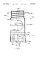
- FIGS. 1a and 1bare, respectively, side views of the side and top loading coupling elements of the present invention.
- FIG. 2is a side view of the locking collar of the present invention, shown along a direction wherein the rod seating grooves thereof are aligned perpendicular to the plane of view;
- FIG. 3is a side view of the top locking nut which is an aspect of the present invention.
- FIG. 4is a side view of a rod securing sleeve which is utilized in embodiments of the present invention
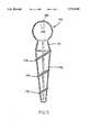
- FIG. 5is a side view of the pedicle screw which is an aspect of certain embodiments of the present invention.
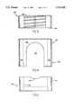
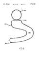
- FIG. 6is a side view of the blade portion of the lamina hook aspect of the present invention.
- FIG. 7is a side view of the plate portion of the sacral block aspect of the present invention.
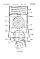
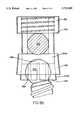
- FIGS. 8a and 8bare, respectively, side views of the coupling elements of FIGS. 1a and 1b, mounted on ball head of the type illustrated FIGS. 5, 6, and 7 including the locking collar of FIG. 2, the locking nut of FIG. 3, the rod securing sleeve FIG. 4, and a rod;
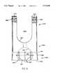
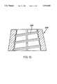
- FIGS. 9a and 9bare, respectively, side views of side and top loading coupling elements having a threading on the exterior surface of the lower portions thereof;
- FIG. 10is a side view of the threaded locking collar which is an aspect of the present invention.
- FIGS. 1a and 1balternative preferred embodiments of the coupling element 100a,100b of the present invention is shown in side views, wherein critical features of the interior of the element are shown in phantom.
- the coupling elements 100a,100beach comprise a generally cylindrical body which may be conceptually separated into a lower portion 102a,102b and an upper portion 106a,106b, each of which shall be described more fully hereinbelow.
- the upper portion 106a of the coupling element 100a shown in FIG. 1amay be further subdivided into an intermediate portion 104a and a top portion 105a.
- the exterior surface 108a,108b of the bodyis tapered in the elongate direction such that the body is wider at the bottom 110a,110b of the lower portion 102a,102b than at the top 112a,112b thereof.
- the bottom 110a,110b of the element 100a,100bincludes an opening 114a,114b, defined by annular lip 113a,113b, which forms the mouth of an interior chamber 116a,116b.
- the diameter of the opening 114a,114bwhen otherwise unaffected by external deflecting forces, is more narrow than the maximum diameter A--A of the interior chamber 116a,116b.
- the interior chamber 116a,116bhas a generally curvate inner surface 118a, 118bwhich is correspondingly shaped to receive a semi-spherical shaped object.
- the exterior surface of the lower portion 102a,102bincludes a series of slots 120a,120bwhich extend vertically upward from the bottom 110a,110b of the element 100a,100b to a point which is closer to the top 112a,112b of the lower portion 102a,102b than the maximum horizontal diameter A--A.
- the slots 120a,120bare provided in order that the application of an external deflecting force may widen or narrow the opening 114a,114b therein permitting the insertion of an object which is larger than the undeflected diameter of the opening 114a,114b or conversely, providing for the retention of an object which is smaller than the undeflected diameter of the opening 114a, 114b.
- the intermediate portion 104a of the generally cylindrical body of the coupling element 100aincludes a large horizontal channel 122a, a rod receiving locus, in the side of the coupling element 100a.
- the channel 122acomprises a curvate inner wall 124a.
- the vertical distance B--B from the top 121a of the channel 122a to the bottom 123a thereofis larger than the diameter of the rod which is to be provided therein. This distance B--B is necessarily larger than the diameter of the rod so that the rod may be translated upward and downward within this channel 122a.
- the maximum channel vertical dimension C--Cis such that the support rod which is positioned therein nests fully within the coupling element 100a, and does not extend beyond the lateral extent thereof (which would prevent a rod securing sleeve, as shall be described with reference to FIG. 4 from sliding into retaining relationship with the rod within the channel 122a).
- the top portion 105aof the coupling element 100acomprises a slightly narrower cylindrical core 125a, having a threading 126a thereon.
- This top portion 105a, and the threading 126a thereon,is ideally suited for receiving a top locking nut (see FIG. 3).
- an axial bore 128aextends through the top portion 105a, through the intermediate portion 104a, and into the lower portion 102a.
- the bore 128aprovides a linear passage through which a user may insert a screw-driving tool to access the ball head in the interior chamber 116a, and any structural elements therein.
- upper portion 104b of the generally cylindrical body of the coupling element 100bcomprises a pair of upwardly extending members 107b,109b defining therebetween a vertically oriented channel 122b in the top of the coupling element 100b.
- the channel 122bcomprises a curvate bottom surface 124b which, for example defines a semi-circular cross-section.
- the depth of the channel 122bis such that a support rod which is positioned therein may nest fully within the coupling element 100b, the top of the rod thereby being positioned substantially below the top of the upper portion. This permits the top locking nut (see FIG. 3) to be disposed on the top of the coupling element in a manner described more fully hereinbelow.
- the upper portion 104b of the coupling element 100bwhich comprises a pair of spaced apart upwardly extending members 107b,109b also comprises an external surface threading 126b. These members 107b,109b, and the threading 126b thereon, are ideally suited for receiving a top locking nut (see FIG. 3).
- the locking collar 140comprises a short and hollow tubular body 141 having a pair of opposing grooves 143.
- the grooves 143are provided for the rod to seat against in the collar's initial disposition.
- the interior surface 142 of the locking collar 140also includes a taper.
- the collar 140is designed to translate downward along the lower portion 102a,102b of the coupling element 100a,100b to cause the contraction of the interior volume 116a,116b, thereof, thereby locking therein a ball which had previously been polyaxially retained therein.
- the mutual tapering of the collar 140 and the lower portions 102a,102b of the coupling elements 100a,100beliminatesmeans by which the relative motion of the collar 140 and the coupling element 100a,100b may bind before causing the crush locking of the ball in the interior volume 116a,116b.
- the top locking nut 150comprises an inner threading 152 which is intended to mate with the threading 126a,126b on the upper portions 106a,106b of the coupling elements 100a,100b.
- the bottom surface 154 of the nut 150is intended to seat against either the top surface of the rod, or against the top surface of the rod securing sleeve (see FIGS. 4 and 8a) but is permitted to rotate relative to the sleeve, therein providing a means for driving the sleeve and/or rod downward (as more fully described hereinbelow with respect to the full assembly of the device, and with respect to FIGS. 8a and 8b).
- the sleevecomprises a hollow cylindrical body 162 having an interior diameter which is equal to the outer diameter of the coupling element 100a, so that it may be placed thereover.
- the bottom portion 164 of the rod securing sleeve 160comprises a pair of downwardly extending members 161,163 which define, therebetween, a second channel 166 through which the rod passes.
- the rod securing sleeveis therefore, introduced over the upper portion 106a of the coupling element 100a, once the rod has been inserted in the side channel 122a thereof.
- the downward translation of the rod securing sleeve 160causes the rod to translate downwardly within the channel 122a, along with the locking collar 140, until the locking collar 140 locks the ball head in the interior volume 122a of the coupling element 102a, and the rod is locked in the channel 122a.
- FIG. 5a side view of the screw portion of the present invention, comprising a curvate head is shown.
- the screw 170comprises a head portion 172, a neck 174, and a shaft 176.
- the shaft 176is shown as having a tapered shape with a high pitch thread 178.
- the specific choice of shaft features, such as thread pitch, shaft diameter to thread diameter ratio, and overall shaft shape,should be made be the physician with respect to the conditions of the individual patient's bone, however, this invention is compatible with a wide variety of shaft designs.
- the head portion 172 of the screw 170comprises a semi-spherical shape, which has a recess 180 in it. It is understood that the semi-spherical shape is a section of a sphere, in the embodiment shown the section is greater in extent than a hemisphere, and it correspondingly exhibits an external contour which is equidistant from a center point of the head.
- the major cross-section of the semi-spherical head 172(as shown in the two dimensional illustration of FIG. 5) includes at least 270 degrees of a circle.
- the recess 180defines a receiving locus for the application of a torque for driving the screw 170 into the bone.
- the specific shape of the recess 172may be chosen to cooperate with any suitable screw-driving tool.
- the recess 180may comprise a slot for a flat-headed screwdriver, a crossed recess for a phillips head screwdriver, or most preferably, a hexagonally shaped hole for receiving an allen wrench. It is further preferable that the recess 180 be co-axial with the general elongate axis of the screw 170, and most particularly with respect to the shaft 176. Having the axes of the recess 180 and the shaft 176 co-linear facilitates step of inserting the screw 170 into the bone
- the semi-spherical head portion 172is connected to the shaft 176 at a neck portion 174. While it is preferable that the diameter of the shaft 176 be less than the diameter of the semispherical head 172, it is also preferable that the neck 174 of the screw 170 be narrower than the widest portion of the shaft 176. This preferable dimension permits the screw to be locked at a variety of angles while still being securely joined to the coupling element.
- the blade portion 190comprises a head portion 192 and a C-shaped portion 194.
- the lower extending branch 196 of the C-shaped portion 194comprises a flat member which is understood to be the portion which is inserted under the lamina of the patient's spine.
- the semi-spherical head portion 192is connected to upper extending branch of the C-shaped portion 194 at a neck portion 198.
- the head portion 192 of the blade portioncomprises a semi-spherical shape. It is understood that the semi-spherical shape is a section of a sphere. In the embodiment shown, the section is greater in extent than a hemisphere, and it correspondingly exhibits an external contour which is equidistant from a center point of the head. In a preferred embodiment, the major cross-section of the semi-spherical head 192 includes at least 270 degrees of a circle.
- the block 200comprises a generally planar portion 202 having a pair of through holes 204 therein for receiving therethrough bone screws so that it may be secured to a sacrum. It further includes an upwardly projecting semi-spherical ball 206, which is mounted on a wide short post or neck 207. This semi-spherical ball 206, as are the semi-spherical ball heads of the screw and blade 172 and 192, respectively, is provided for insertion into, and subsequent locking within, the interior volume 116a,116b of the polyaxial coupling element 100a,100b.
- FIGS. 8a and 8bthe coupling elements 100a and 100b, as described more fully above with respect to FIGS. 1a and 1b, respectively, are shown in side views.
- a semi-spherical ball head 172,192,206 of the screw 170 or blade 190 or block 200has been received within the interior chamber 116a,116b;
- the locking collar 140is shown in its locked position about the lower portion 102a,102b;
- the top locking nut 150is threaded onto the upper portion 104a,104b;
- the head 172, 192, or 206 of corresponding elementsPrior to full assembly, the head 172, 192, or 206 of corresponding elements, is free to move polyaxially relative to the coupling element 100a,100b, however, it is prevented from fully separating from the interior chamber 116a,116b by the annular lip 113a,113b at the bottom 110a,110b of the lower portion 102a,102b.
- Implantation of these implant devicesis preceded by the proper preparation of the implantation site.
- a pre-drilled holeis provided in the bone, into which it is desired that the screw 170 may be inserted.
- the head 172,192,206is inserted into the interior chamber 116a,116bof the coupling element 100a,100b.
- the locking collar 140has not yet been forced downward along the outwardly tapered lower portion 102a,102b, thereby permitting rotational and polyaxial relative motion.
- the screw, hook, or sacral blockis affixed to the appropriate prepared site and the support rod 210 is nested within the channel 122a,122b, and disposed on the grooves 143 of the locking collar 140.
- the rod securing sleeve 160is then dropped over the element 100a, such that the grooves 143 of the sleeve 160 are seated against the top of the rod 210.
- the rod securing sleeve 160is not necessary.
- the top locking nut 150is threaded onto the threading 126a,126b of the upper portion 106a,106b.
- the bottom surface 154 of the nut 150seats against the top surface 162 of the rod securing sleeve 160.
- the rod securing sleeve 160is driven downward. This motion causes the rod 210 to translate downward therein forcing the locking collar 140 to descend as well.
- the locking collar 140may be driven downwardly by either interaction solely with the rod 210, or also by direct contact with the downwardly extending members 161,163 of the rod securing sleeve 160.
- the top locking nut 150is advanced directly into contact with the rod 210, which in turn causes the collar 140 to descend.
- the locking collar 140provides an inwardly directed deflecting force which causes the slots 120a,120b in the lower portion 102a,102b of the element to narrow so that the collar may proceed downward
- This deflection inwardcauses the inner surface 118a,118b of the interior chamber 116a,116b to crush lock against the head 172,192,206.
- This clamping forcelocks the angulation of the screw, hook, or block 170,190,200 to the coupling element 100a,100b.
- FIGS. 9a and 9bin which two alternative coupling element embodiments of the present invention are shown in side views, a threaded version of the locking mechanism is described.
- the coupling elements 220a,220bbeing side and top loading variations, respectively, are identical to the coupling elements 100a,100b as set forth hereinabove with reference to FIGS. 1a and 1b, but for the threading 226a,226b disposed on the tapered lower portions 222a,222b thereof.
- This threading 226a,226bis provided to engage a threading 224 on a locking collar 228, as is illustrated in FIG. 10.
- This locking collar 228is identical to the collar 140 set forth hereinabove with reference to FIG. 2, but for the interior threading 224 thereof.
- the collar 228is selectively advanceable to lock the head 172,192,206 in the interior volume 230a,230b of the coupling element 220a,220bindependent of rod and/or securing sleeve contact therewith
Landscapes
- Health & Medical Sciences (AREA)
- Orthopedic Medicine & Surgery (AREA)
- Life Sciences & Earth Sciences (AREA)
- Neurology (AREA)
- Surgery (AREA)
- Heart & Thoracic Surgery (AREA)
- Engineering & Computer Science (AREA)
- Biomedical Technology (AREA)
- Nuclear Medicine, Radiotherapy & Molecular Imaging (AREA)
- Medical Informatics (AREA)
- Molecular Biology (AREA)
- Animal Behavior & Ethology (AREA)
- General Health & Medical Sciences (AREA)
- Public Health (AREA)
- Veterinary Medicine (AREA)
- Neurosurgery (AREA)
- Surgical Instruments (AREA)
Abstract
Description
Claims (10)
Priority Applications (1)
| Application Number | Priority Date | Filing Date | Title |
|---|---|---|---|
| US08/665,402US5733285A (en) | 1995-07-13 | 1996-06-18 | Polyaxial locking mechanism |
Applications Claiming Priority (2)
| Application Number | Priority Date | Filing Date | Title |
|---|---|---|---|
| US08/502,285US5549608A (en) | 1995-07-13 | 1995-07-13 | Advanced polyaxial locking screw and coupling element device for use with rod fixation apparatus |
| US08/665,402US5733285A (en) | 1995-07-13 | 1996-06-18 | Polyaxial locking mechanism |
Related Parent Applications (1)
| Application Number | Title | Priority Date | Filing Date |
|---|---|---|---|
| US08/502,285Continuation-In-PartUS5549608A (en) | 1995-07-13 | 1995-07-13 | Advanced polyaxial locking screw and coupling element device for use with rod fixation apparatus |
Publications (1)
| Publication Number | Publication Date |
|---|---|
| US5733285Atrue US5733285A (en) | 1998-03-31 |
Family
ID=46252048
Family Applications (1)
| Application Number | Title | Priority Date | Filing Date |
|---|---|---|---|
| US08/665,402Expired - LifetimeUS5733285A (en) | 1995-07-13 | 1996-06-18 | Polyaxial locking mechanism |
Country Status (1)
| Country | Link |
|---|---|
| US (1) | US5733285A (en) |
Cited By (177)
| Publication number | Priority date | Publication date | Assignee | Title |
|---|---|---|---|---|
| US6053917A (en)* | 1996-09-24 | 2000-04-25 | Sdgi Holdings, Inc. | Multi-axial bone screw assembly |
| WO2000024325A1 (en)* | 1998-10-28 | 2000-05-04 | Alphatec Manufacturing, Inc. | Anterior cervical plate and fixation system |
| US6063090A (en)* | 1996-12-12 | 2000-05-16 | Synthes (U.S.A.) | Device for connecting a longitudinal support to a pedicle screw |
| US6187005B1 (en) | 1998-09-11 | 2001-02-13 | Synthes (Usa) | Variable angle spinal fixation system |
| WO2001010317A1 (en)* | 1999-08-05 | 2001-02-15 | Traiber, S.A. | Intervertebral fixing system used in treatments of the spinal column |
| WO2001015612A1 (en) | 1999-09-01 | 2001-03-08 | Sdgi Holdings, Inc. | Multi-axial bone screw assembly |
| US6248105B1 (en) | 1997-05-17 | 2001-06-19 | Synthes (U.S.A.) | Device for connecting a longitudinal support with a pedicle screw |
| US6254602B1 (en)* | 1999-05-28 | 2001-07-03 | Sdgi Holdings, Inc. | Advanced coupling device using shape-memory technology |
| US6273888B1 (en)* | 1999-05-28 | 2001-08-14 | Sdgi Holdings, Inc. | Device and method for selectively preventing the locking of a shape-memory alloy coupling system |
| WO2002000124A1 (en)* | 2000-06-30 | 2002-01-03 | Sdgi Holdings, Inc. | Intervertebral linking device |
| FR2810873A1 (en)* | 2000-06-30 | 2002-01-04 | Henry Graf | Intervertebral coupling for two or more vertebrae has intermediate element between fixed and mobile components to allow movement |
| US6371957B1 (en) | 1997-01-22 | 2002-04-16 | Synthes (Usa) | Device for connecting a longitudinal bar to a pedicle screw |
| US6413258B1 (en) | 1999-08-12 | 2002-07-02 | Osteotech, Inc. | Rod-to-rod coupler |
| US20020120272A1 (en)* | 1998-06-17 | 2002-08-29 | Hansen Yuan | Device for securing spinal rods |
| US20020156474A1 (en)* | 2001-04-20 | 2002-10-24 | Michael Wack | Polyaxial locking plate |
| US20030055426A1 (en)* | 2001-09-14 | 2003-03-20 | John Carbone | Biased angulation bone fixation assembly |
| US6554834B1 (en) | 1999-10-07 | 2003-04-29 | Stryker Spine | Slotted head pedicle screw assembly |
| US20030153911A1 (en)* | 2002-02-13 | 2003-08-14 | Endius Incorporated | Apparatus for connecting a longitudinal member to a bone portion |
| US6679883B2 (en) | 2001-10-31 | 2004-01-20 | Ortho Development Corporation | Cervical plate for stabilizing the human spine |
| US20040153077A1 (en)* | 2000-11-10 | 2004-08-05 | Lutz Biedermann | Bone screw |
| US20040265997A1 (en)* | 2003-06-27 | 2004-12-30 | Park Sung-Soo | Bio-artificial liver system |
| US20050033298A1 (en)* | 2001-10-31 | 2005-02-10 | Ortho Development Corporation | Cervical plate for stabilizing the human spine |
| US20050048775A1 (en)* | 2001-07-19 | 2005-03-03 | Hilke Donohue | Depositing a tantalum film |
| US20050096653A1 (en)* | 2003-11-03 | 2005-05-05 | Doubler Robert L. | Bone fixation system with low profile fastener |
| US6893443B2 (en) | 1999-07-07 | 2005-05-17 | Synthes (U.S.A) | Angle-adjustable bone screw and fixation device |
| US20050130254A1 (en)* | 2003-12-16 | 2005-06-16 | Park Sung-Soo | Drug testing system with bio-artificial liver |
| US20050154393A1 (en)* | 2003-12-30 | 2005-07-14 | Thomas Doherty | Bone anchor assemblies and methods of manufacturing bone anchor assemblies |
| US20050154391A1 (en)* | 2003-12-30 | 2005-07-14 | Thomas Doherty | Bone anchor assemblies |
| US20050187548A1 (en)* | 2004-01-13 | 2005-08-25 | Butler Michael S. | Pedicle screw constructs for spine fixation systems |
| US6945972B2 (en) | 2000-08-24 | 2005-09-20 | Synthes | Apparatus for connecting a bone fastener to a longitudinal rod |
| US20050228392A1 (en)* | 2004-04-12 | 2005-10-13 | Keyer Thomas R | Rod persuader |
| US20050234452A1 (en)* | 2004-04-16 | 2005-10-20 | Malandain Hugues F | Subcutaneous support |
| US20050234451A1 (en)* | 2004-04-16 | 2005-10-20 | Markworth Aaron D | Pedicle screw assembly |
| US20050234456A1 (en)* | 2004-04-16 | 2005-10-20 | Malandain Hugues F | Plate system for minimally invasive support of the spine |
| US20050261687A1 (en)* | 2004-04-20 | 2005-11-24 | Laszlo Garamszegi | Pedicle screw assembly |
| US20050267472A1 (en)* | 2002-03-27 | 2005-12-01 | Biedermann Motech Gmbh | Bone anchoring device for stabilising bone segments and seat part of a bone anchoring device |
| US6997927B2 (en) | 2000-12-08 | 2006-02-14 | Jackson Roger P | closure for rod receiving orthopedic implant having a pair of spaced apertures for removal |
| US20060116677A1 (en)* | 2004-12-01 | 2006-06-01 | Burd Brian A | Side-loading bone anchor |
| US20060116687A1 (en)* | 2004-11-30 | 2006-06-01 | Miller Keith E | Side-loading adjustable bone anchor |
| EP1642542A3 (en)* | 1998-04-03 | 2006-06-14 | Aesculap II, Inc. | Locking mechanism for spinal fixation |
| US20060149237A1 (en)* | 2004-12-30 | 2006-07-06 | Markworth Aaron D | Screw with deployable interlaced dual rods |
| US20060149252A1 (en)* | 2004-12-30 | 2006-07-06 | Markworth Aaron D | Bone anchorage screw with built-in hinged plate |
| US20060149233A1 (en)* | 2004-12-16 | 2006-07-06 | Richelsoph Marc E | Locking mechanism |
| US20060173456A1 (en)* | 2005-01-31 | 2006-08-03 | Hawkes David T | Polyaxial pedicle screw assembly |
| US20060200149A1 (en)* | 2005-02-22 | 2006-09-07 | Hoy Robert W | Polyaxial orhtopedic fastening apparatus |
| US20060217710A1 (en)* | 2005-03-07 | 2006-09-28 | Abdou M S | Occipital fixation system and method of use |
| US20060217716A1 (en)* | 2005-03-22 | 2006-09-28 | Baker Daniel R | Spinal fixation locking mechanism |
| US20060241599A1 (en)* | 2003-06-27 | 2006-10-26 | Konieczynski David D | Polyaxial Bone Screw |
| US20060264933A1 (en)* | 2005-05-04 | 2006-11-23 | Baker Daniel R | Multistage spinal fixation locking mechanism |
| US20070049932A1 (en)* | 2005-08-23 | 2007-03-01 | Aesculap Ag & Co. Kg | Rod to rod connector |
| US20070090238A1 (en)* | 2005-10-20 | 2007-04-26 | Sdgi Holdings, Inc. | Bottom loading multi-axial screw assembly |
| US20070123870A1 (en)* | 2005-07-18 | 2007-05-31 | Jeon Dong M | Bi-polar screw assembly |
| US20070123867A1 (en)* | 2005-07-29 | 2007-05-31 | X-Spine Systems, Inc. | Capless multiaxial screw and spinal fixation assembly and method |
| US20070161995A1 (en)* | 2005-10-06 | 2007-07-12 | Trautwein Frank T | Polyaxial Screw |
| US20070161990A1 (en)* | 2005-12-21 | 2007-07-12 | Zimmer Spine, Inc. | Spinal implant hooks and systems |
| US20070173827A1 (en)* | 2006-01-20 | 2007-07-26 | Sdgi Holdings, Inc. | Adjustable connector for attachment to a rod in a medical application |
| US20070233078A1 (en)* | 2006-01-27 | 2007-10-04 | Justis Jeff R | Pivoting joints for spinal implants including designed resistance to motion and methods of use |
| US20070233072A1 (en)* | 2006-03-01 | 2007-10-04 | Sdgi Holdings, Inc. | Modular fastener assemblies for spinal stabilization systems and methods |
| US20070270839A1 (en)* | 2006-04-05 | 2007-11-22 | Dong Myung Jeon | Multi-axial double locking bone screw assembly |
| US20070270813A1 (en)* | 2006-04-12 | 2007-11-22 | Laszlo Garamszegi | Pedicle screw assembly |
| US7316684B1 (en)* | 1999-07-22 | 2008-01-08 | Stryker Spine | Multiaxial connection for osteosynthesis |
| US20080015579A1 (en)* | 2006-04-28 | 2008-01-17 | Whipple Dale E | Large diameter bone anchor assembly |
| US20080015576A1 (en)* | 2006-04-28 | 2008-01-17 | Whipple Dale E | Large diameter bone anchor assembly |
| US20080045953A1 (en)* | 2006-07-14 | 2008-02-21 | Laszlo Garamszegi | Pedicle screw assembly with inclined surface seat |
| US20080071277A1 (en)* | 2004-10-25 | 2008-03-20 | Warnick David R | Pedicle Screw Systems and Methods of Assembling/Installing the Same |
| US20080108992A1 (en)* | 2006-11-08 | 2008-05-08 | Ebi, L.P. | Multi-axial bone fixation apparatus |
| US20080140075A1 (en)* | 2006-12-07 | 2008-06-12 | Ensign Michael D | Press-On Pedicle Screw Assembly |
| US20080147121A1 (en)* | 2006-01-27 | 2008-06-19 | Warsaw Orthopedic, Inc. | Multi-Axial Screw Assembly |
| US20080177315A1 (en)* | 2006-12-20 | 2008-07-24 | Aesculap Ii, Inc. | Rod to Rod Connector |
| US20080183223A1 (en)* | 2005-09-26 | 2008-07-31 | Jeon Dong M | Hybrid jointed bone screw system |
| US20080195213A1 (en)* | 2007-02-12 | 2008-08-14 | Brigham Young University | Spinal implant |
| US20080234755A1 (en)* | 2007-01-29 | 2008-09-25 | Polaris Biotechnology, Inc. | Craniospinal fusion method and apparatus |
| US20080269742A1 (en)* | 2007-04-25 | 2008-10-30 | Levy Mark M | Connector assembly for bone anchoring element |
| US20090018584A1 (en)* | 2007-01-29 | 2009-01-15 | Polaris Biotechnology, Inc. | Vertebra attachment method and system |
| US20090069852A1 (en)* | 2007-09-06 | 2009-03-12 | Warsaw Orthopedic, Inc. | Multi-Axial Bone Anchor Assembly |
| US20090105756A1 (en)* | 2007-10-23 | 2009-04-23 | Marc Richelsoph | Spinal implant |
| US20090143823A1 (en)* | 2008-11-13 | 2009-06-04 | Jeon Dong M | Transverse connector system for spinal rods |
| US20090171395A1 (en)* | 2007-12-28 | 2009-07-02 | Jeon Dong M | Dynamic spinal rod system |
| US20090192548A1 (en)* | 2008-01-25 | 2009-07-30 | Jeon Dong M | Pedicle-laminar dynamic spinal stabilization device |
| US20090194206A1 (en)* | 2008-01-31 | 2009-08-06 | Jeon Dong M | Systems and methods for wrought nickel/titanium alloy flexible spinal rods |
| US20090254125A1 (en)* | 2008-04-03 | 2009-10-08 | Daniel Predick | Top Loading Polyaxial Spine Screw Assembly With One Step Lockup |
| US20090292308A1 (en)* | 2008-05-22 | 2009-11-26 | K2M, Inc. | Spinal fixation system |
| US20090318967A1 (en)* | 2007-01-23 | 2009-12-24 | Dong Myung Jeon | Spacer for use in a surgical operation for spinous process of spine |
| US20100049256A1 (en)* | 2007-01-30 | 2010-02-25 | Dong Myung Jeon | Anterior cerivcal plating system |
| US20100063546A1 (en)* | 2008-09-09 | 2010-03-11 | Warsaw Orthopedic, Inc. | Offset vertebral rod connector |
| US20100063553A1 (en)* | 2004-10-25 | 2010-03-11 | X-Spine Systems, Inc. | Bone fixation method |
| US20100076448A1 (en)* | 2003-12-29 | 2010-03-25 | Abdou M Samy | Plating system for bone fixation and method of implantation |
| US20100087873A1 (en)* | 2008-10-06 | 2010-04-08 | Warsaw Orthopedics, Inc. | Surgical Connectors for Attaching an Elongated Member to a Bone |
| US20100121384A1 (en)* | 2004-06-14 | 2010-05-13 | Abdou M Samy | Occipital fixation system and method of use |
| US7722652B2 (en) | 2006-01-27 | 2010-05-25 | Warsaw Orthopedic, Inc. | Pivoting joints for spinal implants including designed resistance to motion and methods of use |
| EP2191780A1 (en) | 2008-11-28 | 2010-06-02 | Biedermann Motech GmbH | Receiving part for receiving a rod for coupling the rod to a bone anchoring element and a bone anchoring device with such a receiving part |
| US20100152788A1 (en)* | 2005-10-04 | 2010-06-17 | X-Spine Systems, Inc. | Pedicle screw system with provisional locking aspects |
| US20100160977A1 (en)* | 2008-10-14 | 2010-06-24 | Gephart Matthew P | Low Profile Dual Locking Fixation System and Offset Anchor Member |
| EP2201903A1 (en) | 2008-12-29 | 2010-06-30 | Biedermann Motech GmbH | Receiving part for receiving a rod for coupling the rod to a bone anchoring element and bone anchoring device with such a receiving part |
| US20100179597A1 (en)* | 2007-01-29 | 2010-07-15 | Polaris Biotechnology, Inc. | Craniospinal fusion method and apparatus |
| US20100198272A1 (en)* | 2007-07-20 | 2010-08-05 | Thomas Keyer | Polyaxial bone fixation element |
| US20100211106A1 (en)* | 2009-02-19 | 2010-08-19 | Bowden Anton E | Compliant Dynamic Spinal Implant And Associated Methods |
| US20100217334A1 (en)* | 2009-02-23 | 2010-08-26 | Hawkes David T | Press-On Link For Surgical Screws |
| US7794478B2 (en) | 2007-01-15 | 2010-09-14 | Innovative Delta Technology, Llc | Polyaxial cross connector and methods of use thereof |
| US20100241175A1 (en)* | 2009-03-20 | 2010-09-23 | Spinal USA LLC | Pedicle screws and methods of using the same |
| US20100241232A1 (en)* | 2007-02-12 | 2010-09-23 | Peter Halverson | Spinal implant |
| US20100312282A1 (en)* | 2005-02-18 | 2010-12-09 | Samy Abdou | Devices and methods for dynamic fixation of skeletal structure |
| US7879075B2 (en) | 2002-02-13 | 2011-02-01 | Zimmer Spine, Inc. | Methods for connecting a longitudinal member to a bone portion |
| US20110093021A1 (en)* | 2009-10-16 | 2011-04-21 | Jonathan Fanger | Bone Anchor Assemblies and Methods of Manufacturing and Use Thereof |
| US20110106166A1 (en)* | 2009-04-15 | 2011-05-05 | Tom Keyer | Revision connector for spinal constructs |
| US20110160779A1 (en)* | 2008-09-05 | 2011-06-30 | Synthes Usa, Llc | Bone fixation assembly |
| US20110245876A1 (en)* | 2010-04-05 | 2011-10-06 | Brumfield David L | Fully-Adjustable bone fixation device |
| US8097025B2 (en) | 2005-10-25 | 2012-01-17 | X-Spine Systems, Inc. | Pedicle screw system configured to receive a straight or curved rod |
| EP1996094A4 (en)* | 2006-03-20 | 2012-03-28 | N Spine Inc | Poly-axial bone screw mating seat |
| US8162990B2 (en) | 2006-11-16 | 2012-04-24 | Spine Wave, Inc. | Multi-axial spinal fixation system |
| US8167910B2 (en) | 2006-10-16 | 2012-05-01 | Innovative Delta Technology Llc | Bone screw and associated assembly and methods of use thereof |
| US20120109218A1 (en)* | 2010-10-29 | 2012-05-03 | Warsaw Orthopedic, Inc. | Directional Control for a Multi-Axial Screw Assembly |
| US8197517B1 (en) | 2007-05-08 | 2012-06-12 | Theken Spine, Llc | Frictional polyaxial screw assembly |
| EP2462888A1 (en) | 2010-12-10 | 2012-06-13 | Biedermann Technologies GmbH & Co. KG | Receiving part for receiving a rod for coupling the rod to a bone anchoring element and bone anchoring device with such a receiving part |
| EP2462886A1 (en) | 2010-12-10 | 2012-06-13 | Biedermann Technologies GmbH & Co. KG | Receiving part for receiving a rod for coupling the rod to a bone anchoring element and a bone anchoring device |
| US20120203281A1 (en)* | 2011-02-05 | 2012-08-09 | Alphatec Spine, Inc | Semi-rigid screw assembly |
| US20120209332A1 (en)* | 2011-02-14 | 2012-08-16 | Pioneer Surgical Technology, Inc. | Spinal Fixation System And Method |
| US20120215264A1 (en)* | 2011-02-23 | 2012-08-23 | Choon Sung Lee | Extensible pedicle screw coupling device |
| US20130018428A1 (en)* | 2011-07-15 | 2013-01-17 | Michael Harper | Orthopedic Fixation Devices and Methods of Installation Thereof |
| US8361129B2 (en) | 2006-04-28 | 2013-01-29 | Depuy Spine, Inc. | Large diameter bone anchor assembly |
| US8388660B1 (en) | 2006-08-01 | 2013-03-05 | Samy Abdou | Devices and methods for superior fixation of orthopedic devices onto the vertebral column |
| US20130096623A1 (en)* | 2011-09-15 | 2013-04-18 | Lutz Biedermann | Polyaxial bone anchoring device with enlarged pivot angle |
| US8636778B2 (en) | 2009-02-11 | 2014-01-28 | Pioneer Surgical Technology, Inc. | Wide angulation coupling members for bone fixation system |
| US8771319B2 (en) | 2012-04-16 | 2014-07-08 | Aesculap Implant Systems, Llc | Rod to rod cross connector |
| US8828056B2 (en) | 2012-04-16 | 2014-09-09 | Aesculap Implant Systems, Llc | Rod to rod cross connector |
| US8882817B2 (en) | 2010-08-20 | 2014-11-11 | K2M, Inc. | Spinal fixation system |
| US8894687B2 (en) | 2011-04-25 | 2014-11-25 | Nexus Spine, L.L.C. | Coupling system for surgical construct |
| US8940024B2 (en) | 2007-07-31 | 2015-01-27 | Biedermann Technologies Gmbh & Co. Kg | Bone anchoring device |
| US8979898B2 (en) | 2013-02-20 | 2015-03-17 | K2M, Inc. | Iliosacral polyaxial screw |
| US9084634B1 (en) | 2010-07-09 | 2015-07-21 | Theken Spine, Llc | Uniplanar screw |
| US9101496B2 (en) | 2011-11-30 | 2015-08-11 | Zimmer, Inc. | Ultrasonic orthopedic taper dissociation device and method |
| US9157497B1 (en) | 2009-10-30 | 2015-10-13 | Brigham Young University | Lamina emergent torsional joint and related methods |
| US9241739B2 (en) | 2008-09-12 | 2016-01-26 | DePuy Synthes Products, Inc. | Spinal stabilizing and guiding fixation system |
| US9247962B2 (en) | 2011-08-15 | 2016-02-02 | K2M, Inc. | Laminar hook insertion device |
| US9320546B2 (en) | 2008-09-29 | 2016-04-26 | DePuy Synthes Products, Inc. | Polyaxial bottom-loading screw and rod assembly |
| US9326796B2 (en) | 2008-11-03 | 2016-05-03 | DePuy Synthes Products, Inc. | Uni-planer bone fixation assembly |
| US9333008B2 (en) | 2010-02-19 | 2016-05-10 | Brigham Young University | Serpentine spinal stability device |
| US9393049B2 (en) | 2010-08-20 | 2016-07-19 | K2M, Inc. | Spinal fixation system |
| US9421041B2 (en) | 2008-09-09 | 2016-08-23 | Marc E. Richelsoph | Polyaxial screw assembly |
| US9439681B2 (en) | 2007-07-20 | 2016-09-13 | DePuy Synthes Products, Inc. | Polyaxial bone fixation element |
| CN105997225A (en)* | 2016-05-12 | 2016-10-12 | 吉林大学 | Nut downward-screwed type cutting sleeve shaped screw |
| US9510862B2 (en) | 2009-06-17 | 2016-12-06 | DePuy Synthes Products, Inc. | Revision connector for spinal constructs |
| US9526531B2 (en) | 2013-10-07 | 2016-12-27 | Intelligent Implant Systems, Llc | Polyaxial plate rod system and surgical procedure |
| US9642651B2 (en) | 2014-06-12 | 2017-05-09 | Brigham Young University | Inverted serpentine spinal stability device and associated methods |
| US9827023B2 (en) | 2007-01-29 | 2017-11-28 | Life Spine, Inc. | Craniospinal fusion method and apparatus |
| US9844398B2 (en) | 2012-05-11 | 2017-12-19 | Orthopediatrics Corporation | Surgical connectors and instrumentation |
| US9848918B2 (en) | 2005-11-21 | 2017-12-26 | DePuy Synthes Products, Inc. | Polyaxial bone anchors with increased angulation |
| US9877747B2 (en) | 2009-09-02 | 2018-01-30 | Globus Medical, Inc. | Spine stabilization system |
| US9895171B2 (en)* | 2014-07-29 | 2018-02-20 | Transcendental Spine, Llc | Modular polyaxial bone screw |
| US9962194B2 (en) | 2007-01-15 | 2018-05-08 | Innovative Delta Technology, Llc | Polyaxial spinal stabilizer connector and methods of use thereof |
| US9993269B2 (en) | 2011-07-15 | 2018-06-12 | Globus Medical, Inc. | Orthopedic fixation devices and methods of installation thereof |
| US10485594B2 (en) | 2016-10-04 | 2019-11-26 | Amendia, Inc. | Modular tulip assembly |
| US10507043B1 (en) | 2017-10-11 | 2019-12-17 | Seaspine Orthopedics Corporation | Collet for a polyaxial screw assembly |
| US10543107B2 (en) | 2009-12-07 | 2020-01-28 | Samy Abdou | Devices and methods for minimally invasive spinal stabilization and instrumentation |
| US10548740B1 (en) | 2016-10-25 | 2020-02-04 | Samy Abdou | Devices and methods for vertebral bone realignment |
| US10575961B1 (en) | 2011-09-23 | 2020-03-03 | Samy Abdou | Spinal fixation devices and methods of use |
| US10603083B1 (en) | 2010-07-09 | 2020-03-31 | Theken Spine, Llc | Apparatus and method for limiting a range of angular positions of a screw |
| US10675061B2 (en) | 2016-02-26 | 2020-06-09 | Medos International Sarl | Polyaxial bone fixation element |
| US10695105B2 (en) | 2012-08-28 | 2020-06-30 | Samy Abdou | Spinal fixation devices and methods of use |
| US10722271B2 (en) | 2014-02-20 | 2020-07-28 | K2M, Inc. | Spinal fixation device |
| US10722276B2 (en) | 2013-03-14 | 2020-07-28 | K2M, Inc. | Taper lock hook |
| US10857003B1 (en) | 2015-10-14 | 2020-12-08 | Samy Abdou | Devices and methods for vertebral stabilization |
| US10918498B2 (en) | 2004-11-24 | 2021-02-16 | Samy Abdou | Devices and methods for inter-vertebral orthopedic device placement |
| US10973648B1 (en) | 2016-10-25 | 2021-04-13 | Samy Abdou | Devices and methods for vertebral bone realignment |
| US11006982B2 (en) | 2012-02-22 | 2021-05-18 | Samy Abdou | Spinous process fixation devices and methods of use |
| US11026730B2 (en) | 2017-05-10 | 2021-06-08 | Medos International Sarl | Bone anchors with drag features and related methods |
| US11154331B2 (en) | 2016-10-04 | 2021-10-26 | Spinal Elements, Inc. | Modular tulip assembly |
| US11173040B2 (en) | 2012-10-22 | 2021-11-16 | Cogent Spine, LLC | Devices and methods for spinal stabilization and instrumentation |
| US11179248B2 (en) | 2018-10-02 | 2021-11-23 | Samy Abdou | Devices and methods for spinal implantation |
| CN114366303A (en)* | 2021-12-27 | 2022-04-19 | 北京双翼麒电子有限公司 | Endoscope robot and endoscope operating system |
| EP4074271A1 (en) | 2021-04-15 | 2022-10-19 | Biedermann Technologies GmbH & Co. KG | Polyaxial bone anchoring device |
| US12114898B2 (en) | 2020-11-19 | 2024-10-15 | K2M, Inc. | Modular head assembly for spinal fixation |
| US12213704B1 (en) | 2024-06-18 | 2025-02-04 | Complex Spinal, LLC | Modular spinal fixation screw |
| US12245796B1 (en) | 2024-05-14 | 2025-03-11 | Complex Spinal, LLC | Spinal fixation system having a lockable connector |
| US12245794B1 (en) | 2024-05-14 | 2025-03-11 | Complex Spinal, LLC | Spinal fixation system having a low profile lockable connector |
| US12262921B2 (en) | 2020-06-26 | 2025-04-01 | K2M, Inc. | Modular head assembly |
| US12310631B2 (en) | 2021-03-05 | 2025-05-27 | Medos International Sárl | Multi-feature polyaxial screw |
Citations (3)
| Publication number | Priority date | Publication date | Assignee | Title |
|---|---|---|---|---|
| US5261913A (en)* | 1989-07-26 | 1993-11-16 | J.B.S. Limited Company | Device for straightening, securing, compressing and elongating the spinal column |
| US5443467A (en)* | 1993-03-10 | 1995-08-22 | Biedermann Motech Gmbh | Bone screw |
| US5520690A (en)* | 1995-04-13 | 1996-05-28 | Errico; Joseph P. | Anterior spinal polyaxial locking screw plate assembly |
- 1996
- 1996-06-18USUS08/665,402patent/US5733285A/ennot_activeExpired - Lifetime
Patent Citations (3)
| Publication number | Priority date | Publication date | Assignee | Title |
|---|---|---|---|---|
| US5261913A (en)* | 1989-07-26 | 1993-11-16 | J.B.S. Limited Company | Device for straightening, securing, compressing and elongating the spinal column |
| US5443467A (en)* | 1993-03-10 | 1995-08-22 | Biedermann Motech Gmbh | Bone screw |
| US5520690A (en)* | 1995-04-13 | 1996-05-28 | Errico; Joseph P. | Anterior spinal polyaxial locking screw plate assembly |
Cited By (413)
| Publication number | Priority date | Publication date | Assignee | Title |
|---|---|---|---|---|
| US6053917A (en)* | 1996-09-24 | 2000-04-25 | Sdgi Holdings, Inc. | Multi-axial bone screw assembly |
| US6063090A (en)* | 1996-12-12 | 2000-05-16 | Synthes (U.S.A.) | Device for connecting a longitudinal support to a pedicle screw |
| US6371957B1 (en) | 1997-01-22 | 2002-04-16 | Synthes (Usa) | Device for connecting a longitudinal bar to a pedicle screw |
| US7022122B2 (en) | 1997-01-22 | 2006-04-04 | Synthes (U.S.A.) | Device for connecting a longitudinal bar to a pedicle screw |
| US20060149244A1 (en)* | 1997-01-22 | 2006-07-06 | Synthes (Usa) | Device for connecting a longitudinal bar to a pedicle screw |
| US20030023240A1 (en)* | 1997-01-22 | 2003-01-30 | Synthes (Usa) | Device for connecting a longitudinal bar to a pedicle screw |
| US6248105B1 (en) | 1997-05-17 | 2001-06-19 | Synthes (U.S.A.) | Device for connecting a longitudinal support with a pedicle screw |
| EP1642542A3 (en)* | 1998-04-03 | 2006-06-14 | Aesculap II, Inc. | Locking mechanism for spinal fixation |
| US20010041894A1 (en)* | 1998-05-19 | 2001-11-15 | Campbell Christopher M. | Anterior cervical plate and fixation system |
| US6258089B1 (en)* | 1998-05-19 | 2001-07-10 | Alphatec Manufacturing, Inc. | Anterior cervical plate and fixation system |
| US6626907B2 (en)* | 1998-05-19 | 2003-09-30 | Alphatec Manufacturing, Inc. | Anterior cervical plate and fixation system |
| US7909856B2 (en) | 1998-06-17 | 2011-03-22 | Howmedica Osteonics Corp. | Methods for securing spinal rods |
| US7608095B2 (en) | 1998-06-17 | 2009-10-27 | Howmedica Osteonics Corp. | Device for securing spinal rods |
| US8038702B2 (en) | 1998-06-17 | 2011-10-18 | Howmedica Osteonics Corp. | Device for securing spinal rods |
| US20100268280A1 (en)* | 1998-06-17 | 2010-10-21 | Howmedica Osteonics Corp. | Device for securing spinal rods |
| US20020120272A1 (en)* | 1998-06-17 | 2002-08-29 | Hansen Yuan | Device for securing spinal rods |
| US7780703B2 (en) | 1998-06-17 | 2010-08-24 | Howmedica Osteonics Corp. | Device for securing spinal rods |
| US7819901B2 (en) | 1998-06-17 | 2010-10-26 | Howmedica Osteonics Corp. | Device for securing spinal rods |
| US8808327B2 (en) | 1998-06-17 | 2014-08-19 | Howmedica Osteonics Corp. | Device for securing spinal rods |
| US8313510B2 (en) | 1998-06-17 | 2012-11-20 | Howmedica Osteonics Corp. | Device for securing spinal rods |
| US6565565B1 (en) | 1998-06-17 | 2003-05-20 | Howmedica Osteonics Corp. | Device for securing spinal rods |
| US6187005B1 (en) | 1998-09-11 | 2001-02-13 | Synthes (Usa) | Variable angle spinal fixation system |
| WO2000024325A1 (en)* | 1998-10-28 | 2000-05-04 | Alphatec Manufacturing, Inc. | Anterior cervical plate and fixation system |
| US6273888B1 (en)* | 1999-05-28 | 2001-08-14 | Sdgi Holdings, Inc. | Device and method for selectively preventing the locking of a shape-memory alloy coupling system |
| US6254602B1 (en)* | 1999-05-28 | 2001-07-03 | Sdgi Holdings, Inc. | Advanced coupling device using shape-memory technology |
| US6893443B2 (en) | 1999-07-07 | 2005-05-17 | Synthes (U.S.A) | Angle-adjustable bone screw and fixation device |
| US7316684B1 (en)* | 1999-07-22 | 2008-01-08 | Stryker Spine | Multiaxial connection for osteosynthesis |
| WO2001010317A1 (en)* | 1999-08-05 | 2001-02-15 | Traiber, S.A. | Intervertebral fixing system used in treatments of the spinal column |
| US6413258B1 (en) | 1999-08-12 | 2002-07-02 | Osteotech, Inc. | Rod-to-rod coupler |
| US8298274B2 (en)* | 1999-09-01 | 2012-10-30 | Warsaw Orthopedic, Inc. | Multi-axial bone screw assembly |
| WO2001015612A1 (en) | 1999-09-01 | 2001-03-08 | Sdgi Holdings, Inc. | Multi-axial bone screw assembly |
| US20110071577A1 (en)* | 1999-09-01 | 2011-03-24 | Warsaw Orthopedic, Inc. | Multi-Axial Bone Screw Assembly |
| US6554834B1 (en) | 1999-10-07 | 2003-04-29 | Stryker Spine | Slotted head pedicle screw assembly |
| AU2001270720B2 (en)* | 2000-06-30 | 2007-02-08 | Henry Graf | Intervertebral linking device |
| US20100168797A1 (en)* | 2000-06-30 | 2010-07-01 | Warsaw Orthopedic, Inc. | Intervertebral Connecting Device |
| US20030153912A1 (en)* | 2000-06-30 | 2003-08-14 | Henry Graf | Intervertebral connecting device |
| US7691131B2 (en) | 2000-06-30 | 2010-04-06 | Sofamor S.N.C. | Intervertebral connecting device |
| FR2810873A1 (en)* | 2000-06-30 | 2002-01-04 | Henry Graf | Intervertebral coupling for two or more vertebrae has intermediate element between fixed and mobile components to allow movement |
| WO2002000124A1 (en)* | 2000-06-30 | 2002-01-03 | Sdgi Holdings, Inc. | Intervertebral linking device |
| US20050251141A1 (en)* | 2000-08-24 | 2005-11-10 | Synthes Usa | Apparatus for connecting a bone fastener to a longitudinal rod |
| US6945972B2 (en) | 2000-08-24 | 2005-09-20 | Synthes | Apparatus for connecting a bone fastener to a longitudinal rod |
| US20110125195A1 (en)* | 2000-10-11 | 2011-05-26 | Lutz Biedermann | Bone Screw |
| US8864803B2 (en) | 2000-11-10 | 2014-10-21 | Biedermann Technologies Gmbh & Co. Kg | Bone screw |
| US8945194B2 (en) | 2000-11-10 | 2015-02-03 | Biedermann Technologies Gmbh & Co. Kg | Bone screw |
| US11197694B2 (en) | 2000-11-10 | 2021-12-14 | Biedermann Technologies Gmbh & Co. Kg | Bone screw |
| US9566093B2 (en) | 2000-11-10 | 2017-02-14 | Biedermann Technologies Gmbh & Co. Kg | Bone screw |
| US10058353B2 (en) | 2000-11-10 | 2018-08-28 | Biedermann Technologies Gmbh & Co. Kg | Bone screw |
| US9498256B2 (en) | 2000-11-10 | 2016-11-22 | Biedermann Technologies Gmbh & Co. Kg | Bone screw |
| US20040153077A1 (en)* | 2000-11-10 | 2004-08-05 | Lutz Biedermann | Bone screw |
| US20110066189A2 (en)* | 2000-11-10 | 2011-03-17 | Biedermann Motech Gmbh | Bone screw |
| US8409260B2 (en) | 2000-11-10 | 2013-04-02 | Biedermann Technologies Gmbh & Co. Kg | Bone screw |
| US7785354B2 (en) | 2000-11-10 | 2010-08-31 | Biedermann Motech Gmbh | Bone screw |
| US20060084995A1 (en)* | 2000-11-10 | 2006-04-20 | Biedermann Motech Gmbh | Bone screw |
| US20060106383A1 (en)* | 2000-11-10 | 2006-05-18 | Biedermann Motech Gmbh | Bone screw |
| US6997927B2 (en) | 2000-12-08 | 2006-02-14 | Jackson Roger P | closure for rod receiving orthopedic implant having a pair of spaced apertures for removal |
| US20020156474A1 (en)* | 2001-04-20 | 2002-10-24 | Michael Wack | Polyaxial locking plate |
| US20040030339A1 (en)* | 2001-04-20 | 2004-02-12 | Wack Michael A. | Dual locking plate and associated method |
| US20050048775A1 (en)* | 2001-07-19 | 2005-03-03 | Hilke Donohue | Depositing a tantalum film |
| US20030055426A1 (en)* | 2001-09-14 | 2003-03-20 | John Carbone | Biased angulation bone fixation assembly |
| US9662144B2 (en) | 2001-09-14 | 2017-05-30 | Stryker European Holdings I, Llc | Stabilizing bone using spinal fixation devices and systems |
| US20040243126A1 (en)* | 2001-09-14 | 2004-12-02 | Stryker Spine | Methods for stabilizing bone using spinal fixation devices |
| US8506600B2 (en) | 2001-09-14 | 2013-08-13 | Stryker Spine | Methods for stabilizing bone using spinal fixation devices |
| US8870930B2 (en) | 2001-09-14 | 2014-10-28 | Stryker Spine | Methods for stabilizing bone using spinal fixation devices |
| US6974460B2 (en) | 2001-09-14 | 2005-12-13 | Stryker Spine | Biased angulation bone fixation assembly |
| US10517646B2 (en) | 2001-09-14 | 2019-12-31 | Stryker European Holdings I, Llc | Stabilizing bone using spinal fixation devices and systems |
| US20050033298A1 (en)* | 2001-10-31 | 2005-02-10 | Ortho Development Corporation | Cervical plate for stabilizing the human spine |
| US6679883B2 (en) | 2001-10-31 | 2004-01-20 | Ortho Development Corporation | Cervical plate for stabilizing the human spine |
| US7766947B2 (en) | 2001-10-31 | 2010-08-03 | Ortho Development Corporation | Cervical plate for stabilizing the human spine |
| US9848913B2 (en) | 2002-02-13 | 2017-12-26 | Zimmer Spine, Inc. | Methods for connecting a longitudinal member to a bone portion |
| US20030153911A1 (en)* | 2002-02-13 | 2003-08-14 | Endius Incorporated | Apparatus for connecting a longitudinal member to a bone portion |
| US20110118793A1 (en)* | 2002-02-13 | 2011-05-19 | Zimmer Spine, Inc. | Methods for connecting a longitudinal member to a bone portion |
| US20060293665A1 (en)* | 2002-02-13 | 2006-12-28 | Shluzas Alan E | Apparatus for connecting a longitudinal member to a bone portion |
| US10219835B2 (en) | 2002-02-13 | 2019-03-05 | Zimmer Spine, Inc. | Systems and devices for connecting a longitudinal member to a bone portion |
| US8936624B2 (en) | 2002-02-13 | 2015-01-20 | Zimmer Spine, Inc. | Methods for connecting a longitudinal member to a bone portion |
| US7144396B2 (en) | 2002-02-13 | 2006-12-05 | Endius Incorporated | Apparatus for connecting a longitudinal member to a bone portion |
| US7879075B2 (en) | 2002-02-13 | 2011-02-01 | Zimmer Spine, Inc. | Methods for connecting a longitudinal member to a bone portion |
| US7604656B2 (en) | 2002-02-13 | 2009-10-20 | Zimmer Spine, Inc. | Apparatus for connecting a longitudinal member to a bone portion |
| US7066937B2 (en) | 2002-02-13 | 2006-06-27 | Endius Incorporated | Apparatus for connecting a longitudinal member to a bone portion |
| US8709050B2 (en) | 2002-02-13 | 2014-04-29 | Zimmer Spine, Inc. | Methods for connecting a longitudinal member to a bone portion |
| US7530992B2 (en) | 2002-03-27 | 2009-05-12 | Biedermann Motech Gmbh | Bone anchoring device for stabilising bone segments and seat part of a bone anchoring device |
| US20050267472A1 (en)* | 2002-03-27 | 2005-12-01 | Biedermann Motech Gmbh | Bone anchoring device for stabilising bone segments and seat part of a bone anchoring device |
| US20040265997A1 (en)* | 2003-06-27 | 2004-12-30 | Park Sung-Soo | Bio-artificial liver system |
| US7682377B2 (en) | 2003-06-27 | 2010-03-23 | Depuy Spine, Inc. | Polyaxial bone screw |
| US8313516B2 (en) | 2003-06-27 | 2012-11-20 | Depuy Spine, Inc. | Polyaxial bone screw |
| US20100131018A1 (en)* | 2003-06-27 | 2010-05-27 | Depuy Spine, Inc. | Polyaxial bone screw |
| US9655657B2 (en) | 2003-06-27 | 2017-05-23 | DePuy Synthes Products, Inc. | Polyaxial bone screw |
| US20080140135A1 (en)* | 2003-06-27 | 2008-06-12 | Depuy Spine, Inc. | Polyaxial bone screw |
| US10136924B2 (en) | 2003-06-27 | 2018-11-27 | DePuy Synthes Products, Inc. | Polyaxial bone screw |
| US9463049B2 (en) | 2003-06-27 | 2016-10-11 | DePuy Synthes Products, Inc. | Polyaxial bone screw |
| US8663288B2 (en) | 2003-06-27 | 2014-03-04 | Depuy Synthes Products Llc | Polyaxial bone screw |
| US20060241599A1 (en)* | 2003-06-27 | 2006-10-26 | Konieczynski David D | Polyaxial Bone Screw |
| US10980574B2 (en) | 2003-06-27 | 2021-04-20 | Medos International Sarl | Polyaxial bone screw |
| US9155579B2 (en) | 2003-06-27 | 2015-10-13 | DePuy Synthes Products, Inc. | Polyaxial bone screw |
| AU2004285611B2 (en)* | 2003-11-03 | 2010-10-21 | Spinal, Llc | Bone fixation system with low profile fastener |
| WO2005041821A3 (en)* | 2003-11-03 | 2005-10-13 | Spinal Llc | Bone fixation system with low profile fastener |
| US20050096653A1 (en)* | 2003-11-03 | 2005-05-05 | Doubler Robert L. | Bone fixation system with low profile fastener |
| US7090674B2 (en)* | 2003-11-03 | 2006-08-15 | Spinal, Llc | Bone fixation system with low profile fastener |
| USRE42867E1 (en)* | 2003-11-03 | 2011-10-25 | Spinal, Llc | Bone fixation system with low profile fastener |
| US20050282152A1 (en)* | 2003-12-16 | 2005-12-22 | Hepahope, Inc. | Drug testing with bio-artificial organ slices including for example those derived from liver |
| US20050130254A1 (en)* | 2003-12-16 | 2005-06-16 | Park Sung-Soo | Drug testing system with bio-artificial liver |
| US20100076448A1 (en)* | 2003-12-29 | 2010-03-25 | Abdou M Samy | Plating system for bone fixation and method of implantation |
| US20050154393A1 (en)* | 2003-12-30 | 2005-07-14 | Thomas Doherty | Bone anchor assemblies and methods of manufacturing bone anchor assemblies |
| US20050154391A1 (en)* | 2003-12-30 | 2005-07-14 | Thomas Doherty | Bone anchor assemblies |
| US20050203515A1 (en)* | 2003-12-30 | 2005-09-15 | Thomas Doherty | Bone anchor assemblies |
| US20050159750A1 (en)* | 2003-12-30 | 2005-07-21 | Thomas Doherty | Bone anchor assemblies and methods of manufacturing bone anchor assemblies |
| US7678137B2 (en) | 2004-01-13 | 2010-03-16 | Life Spine, Inc. | Pedicle screw constructs for spine fixation systems |
| US20050187548A1 (en)* | 2004-01-13 | 2005-08-25 | Butler Michael S. | Pedicle screw constructs for spine fixation systems |
| US8092494B2 (en) | 2004-01-13 | 2012-01-10 | Life Spine, Inc. | Pedicle screw constructs for spine fixation systems |
| US20080021473A1 (en)* | 2004-01-13 | 2008-01-24 | Life Spine Llc | Pedicle screw constructs for spine fixation systetms |
| US20050228392A1 (en)* | 2004-04-12 | 2005-10-13 | Keyer Thomas R | Rod persuader |
| US7491207B2 (en)* | 2004-04-12 | 2009-02-17 | Synthes Usa, Llc | Rod persuader |
| US7524323B2 (en) | 2004-04-16 | 2009-04-28 | Kyphon Sarl | Subcutaneous support |
| US7648520B2 (en) | 2004-04-16 | 2010-01-19 | Kyphon Sarl | Pedicle screw assembly |
| US20050234456A1 (en)* | 2004-04-16 | 2005-10-20 | Malandain Hugues F | Plate system for minimally invasive support of the spine |
| US20050234451A1 (en)* | 2004-04-16 | 2005-10-20 | Markworth Aaron D | Pedicle screw assembly |
| US20100076494A1 (en)* | 2004-04-16 | 2010-03-25 | Kyphon Sarl | Pedicle screw assembly |
| US7618418B2 (en) | 2004-04-16 | 2009-11-17 | Kyphon Sarl | Plate system for minimally invasive support of the spine |
| US20050234452A1 (en)* | 2004-04-16 | 2005-10-20 | Malandain Hugues F | Subcutaneous support |
| US8273112B2 (en) | 2004-04-20 | 2012-09-25 | Phygen, Llc | Pedicle screw assembly |
| US20050261687A1 (en)* | 2004-04-20 | 2005-11-24 | Laszlo Garamszegi | Pedicle screw assembly |
| US20100292740A1 (en)* | 2004-04-20 | 2010-11-18 | Laszlo Garamszegi | Pedicle screw assembly |
| US7678139B2 (en) | 2004-04-20 | 2010-03-16 | Allez Spine, Llc | Pedicle screw assembly |
| US20100121384A1 (en)* | 2004-06-14 | 2010-05-13 | Abdou M Samy | Occipital fixation system and method of use |
| US8012185B2 (en) | 2004-10-25 | 2011-09-06 | X-Spine Systems, Inc. | Pedicle screw systems and methods of assembling/installing the same |
| US20080071277A1 (en)* | 2004-10-25 | 2008-03-20 | Warnick David R | Pedicle Screw Systems and Methods of Assembling/Installing the Same |
| US8142481B2 (en) | 2004-10-25 | 2012-03-27 | X-Spine Systems, Inc. | Pedicle screw systems and methods of assembling/installing the same |
| US8147522B2 (en) | 2004-10-25 | 2012-04-03 | X-Spine Systems, Inc. | Bone fixation method |
| US20100063553A1 (en)* | 2004-10-25 | 2010-03-11 | X-Spine Systems, Inc. | Bone fixation method |
| AU2005299617B2 (en)* | 2004-10-25 | 2010-10-28 | X-Spine Systems, Inc. | Pedicle screw systems and methods |
| EP1814473A4 (en)* | 2004-10-25 | 2009-08-05 | Pedicle screw systems and methods | |
| US20100179603A1 (en)* | 2004-10-25 | 2010-07-15 | X-Spine Systems, Inc. | Pedicle screw systems and methods of assembling/installing the same |
| US8092504B2 (en) | 2004-10-25 | 2012-01-10 | X-Spine Systems, Inc. | Pedicle screw systems and methods of assembling/installing the same |
| US10918498B2 (en) | 2004-11-24 | 2021-02-16 | Samy Abdou | Devices and methods for inter-vertebral orthopedic device placement |
| US11992423B2 (en) | 2004-11-24 | 2024-05-28 | Samy Abdou | Devices and methods for inter-vertebral orthopedic device placement |
| US11096799B2 (en) | 2004-11-24 | 2021-08-24 | Samy Abdou | Devices and methods for inter-vertebral orthopedic device placement |
| US7404818B2 (en) | 2004-11-30 | 2008-07-29 | Warsaw Orthopedic, Inc. | Side-loading adjustable bone anchor |
| US20060116687A1 (en)* | 2004-11-30 | 2006-06-01 | Miller Keith E | Side-loading adjustable bone anchor |
| US7674277B2 (en) | 2004-12-01 | 2010-03-09 | Warsaw Orthopedic, Inc. | Side-loading bone anchor |
| US20060116677A1 (en)* | 2004-12-01 | 2006-06-01 | Burd Brian A | Side-loading bone anchor |
| US7744636B2 (en) | 2004-12-16 | 2010-06-29 | Aesculap Ii, Inc. | Locking mechanism |
| US20060149233A1 (en)* | 2004-12-16 | 2006-07-06 | Richelsoph Marc E | Locking mechanism |
| US20060149252A1 (en)* | 2004-12-30 | 2006-07-06 | Markworth Aaron D | Bone anchorage screw with built-in hinged plate |
| US20060149237A1 (en)* | 2004-12-30 | 2006-07-06 | Markworth Aaron D | Screw with deployable interlaced dual rods |
| US7811311B2 (en) | 2004-12-30 | 2010-10-12 | Warsaw Orthopedic, Inc. | Screw with deployable interlaced dual rods |
| US7789899B2 (en) | 2004-12-30 | 2010-09-07 | Warsaw Orthopedic, Inc. | Bone anchorage screw with built-in hinged plate |
| US7445627B2 (en) | 2005-01-31 | 2008-11-04 | Alpinespine, Llc | Polyaxial pedicle screw assembly |
| US20090018591A1 (en)* | 2005-01-31 | 2009-01-15 | Hawkes David T | Polyaxial Pedicle Screw Assembly |
| US20060173456A1 (en)* | 2005-01-31 | 2006-08-03 | Hawkes David T | Polyaxial pedicle screw assembly |
| US20100312282A1 (en)* | 2005-02-18 | 2010-12-09 | Samy Abdou | Devices and methods for dynamic fixation of skeletal structure |
| US8845696B1 (en) | 2005-02-18 | 2014-09-30 | Samy Abdou | Devices and methods for dynamic fixation of skeletal structure |
| US8845701B2 (en) | 2005-02-18 | 2014-09-30 | Samy Abdou | Devices and methods for dynamic fixation of skeletal structure |
| US8398689B2 (en) | 2005-02-18 | 2013-03-19 | Samy Abdou | Devices and methods for dynamic fixation of skeletal structure |
| US8308776B2 (en) | 2005-02-18 | 2012-11-13 | Samy Abdou | Devices and methods for dynamic fixation of skeletal structure |
| US20060200149A1 (en)* | 2005-02-22 | 2006-09-07 | Hoy Robert W | Polyaxial orhtopedic fastening apparatus |
| US7993373B2 (en) | 2005-02-22 | 2011-08-09 | Hoy Robert W | Polyaxial orthopedic fastening apparatus |
| US20120029573A1 (en)* | 2005-02-22 | 2012-02-02 | Triplett Daniel J | Polyaxial Orthopedic Fasteneing Apparatus with Independent Locking Modes |
| US8920468B2 (en)* | 2005-02-22 | 2014-12-30 | Gmedelaware 2 Llc | Polyaxial orthopedic fasteneing apparatus with independent locking modes |
| US20060217710A1 (en)* | 2005-03-07 | 2006-09-28 | Abdou M S | Occipital fixation system and method of use |
| US20060217716A1 (en)* | 2005-03-22 | 2006-09-28 | Baker Daniel R | Spinal fixation locking mechanism |
| US7338491B2 (en) | 2005-03-22 | 2008-03-04 | Spinefrontier Inc | Spinal fixation locking mechanism |
| US20060264933A1 (en)* | 2005-05-04 | 2006-11-23 | Baker Daniel R | Multistage spinal fixation locking mechanism |
| US7811310B2 (en) | 2005-05-04 | 2010-10-12 | Spinefrontier, Inc | Multistage spinal fixation locking mechanism |
| EP1736109A1 (en)* | 2005-06-22 | 2006-12-27 | BIEDERMANN MOTECH GmbH | Bone anchoring device for stabilising bone segments |
| US20070123870A1 (en)* | 2005-07-18 | 2007-05-31 | Jeon Dong M | Bi-polar screw assembly |
| US20070123867A1 (en)* | 2005-07-29 | 2007-05-31 | X-Spine Systems, Inc. | Capless multiaxial screw and spinal fixation assembly and method |
| US20100204738A1 (en)* | 2005-07-29 | 2010-08-12 | X-Spine Systems, Inc. | Capless multiaxial screw and spinal fixation assembly and method |
| US8382806B2 (en) | 2005-07-29 | 2013-02-26 | X-Spine Systems, Inc. | Capless multiaxial screw and spinal fixation assembly and method |
| US8066745B2 (en) | 2005-07-29 | 2011-11-29 | X-Spine Systems, Inc. | Capless multiaxial screw and spinal fixation assembly and method |
| US20070049932A1 (en)* | 2005-08-23 | 2007-03-01 | Aesculap Ag & Co. Kg | Rod to rod connector |
| US7628799B2 (en) | 2005-08-23 | 2009-12-08 | Aesculap Ag & Co. Kg | Rod to rod connector |
| US20080183223A1 (en)* | 2005-09-26 | 2008-07-31 | Jeon Dong M | Hybrid jointed bone screw system |
| US8016866B2 (en) | 2005-10-04 | 2011-09-13 | X-Spine Systems, Inc. | Pedicle screw system with provisional locking aspects |
| US20100152788A1 (en)* | 2005-10-04 | 2010-06-17 | X-Spine Systems, Inc. | Pedicle screw system with provisional locking aspects |
| US7927359B2 (en) | 2005-10-06 | 2011-04-19 | Paradigm Spine, Llc | Polyaxial screw |
| US8470001B2 (en) | 2005-10-06 | 2013-06-25 | Paradigm Spine, Llc | Polyaxial screw |
| US20070161995A1 (en)* | 2005-10-06 | 2007-07-12 | Trautwein Frank T | Polyaxial Screw |
| US20070090238A1 (en)* | 2005-10-20 | 2007-04-26 | Sdgi Holdings, Inc. | Bottom loading multi-axial screw assembly |
| US8002806B2 (en) | 2005-10-20 | 2011-08-23 | Warsaw Orthopedic, Inc. | Bottom loading multi-axial screw assembly |
| US8097025B2 (en) | 2005-10-25 | 2012-01-17 | X-Spine Systems, Inc. | Pedicle screw system configured to receive a straight or curved rod |
| US9848918B2 (en) | 2005-11-21 | 2017-12-26 | DePuy Synthes Products, Inc. | Polyaxial bone anchors with increased angulation |
| US10595908B2 (en) | 2005-11-21 | 2020-03-24 | DePuy Sythes Products, Inc. | Polaxial bone anchors with increased angulation |
| US11432850B2 (en) | 2005-11-21 | 2022-09-06 | DePuy Synthes Products, Inc. | Polyaxial bone anchors with increased angulation |
| US20070161990A1 (en)* | 2005-12-21 | 2007-07-12 | Zimmer Spine, Inc. | Spinal implant hooks and systems |
| US20070173827A1 (en)* | 2006-01-20 | 2007-07-26 | Sdgi Holdings, Inc. | Adjustable connector for attachment to a rod in a medical application |
| US7722652B2 (en) | 2006-01-27 | 2010-05-25 | Warsaw Orthopedic, Inc. | Pivoting joints for spinal implants including designed resistance to motion and methods of use |
| US20080147121A1 (en)* | 2006-01-27 | 2008-06-19 | Warsaw Orthopedic, Inc. | Multi-Axial Screw Assembly |
| US7833252B2 (en) | 2006-01-27 | 2010-11-16 | Warsaw Orthopedic, Inc. | Pivoting joints for spinal implants including designed resistance to motion and methods of use |
| US20070233078A1 (en)* | 2006-01-27 | 2007-10-04 | Justis Jeff R | Pivoting joints for spinal implants including designed resistance to motion and methods of use |
| US8057519B2 (en) | 2006-01-27 | 2011-11-15 | Warsaw Orthopedic, Inc. | Multi-axial screw assembly |
| US20070233072A1 (en)* | 2006-03-01 | 2007-10-04 | Sdgi Holdings, Inc. | Modular fastener assemblies for spinal stabilization systems and methods |
| US8470008B2 (en) | 2006-03-01 | 2013-06-25 | Warsaw Othropedic, Inc. | Modular fastener assemblies for spinal stabilization systems and methods |
| EP1996094A4 (en)* | 2006-03-20 | 2012-03-28 | N Spine Inc | Poly-axial bone screw mating seat |
| US20070270839A1 (en)* | 2006-04-05 | 2007-11-22 | Dong Myung Jeon | Multi-axial double locking bone screw assembly |
| US7896902B2 (en) | 2006-04-05 | 2011-03-01 | Dong Myung Jeon | Multi-axial double locking bone screw assembly |
| US20070270813A1 (en)* | 2006-04-12 | 2007-11-22 | Laszlo Garamszegi | Pedicle screw assembly |
| US20080015576A1 (en)* | 2006-04-28 | 2008-01-17 | Whipple Dale E | Large diameter bone anchor assembly |
| US20080015579A1 (en)* | 2006-04-28 | 2008-01-17 | Whipple Dale E | Large diameter bone anchor assembly |
| US8133262B2 (en) | 2006-04-28 | 2012-03-13 | Depuy Spine, Inc. | Large diameter bone anchor assembly |
| US8361129B2 (en) | 2006-04-28 | 2013-01-29 | Depuy Spine, Inc. | Large diameter bone anchor assembly |
| US8137387B2 (en) | 2006-07-14 | 2012-03-20 | Phygen, LLC. | Pedicle screw assembly with inclined surface seat |
| US20080045953A1 (en)* | 2006-07-14 | 2008-02-21 | Laszlo Garamszegi | Pedicle screw assembly with inclined surface seat |
| US8388660B1 (en) | 2006-08-01 | 2013-03-05 | Samy Abdou | Devices and methods for superior fixation of orthopedic devices onto the vertebral column |
| US8167910B2 (en) | 2006-10-16 | 2012-05-01 | Innovative Delta Technology Llc | Bone screw and associated assembly and methods of use thereof |
| US7699876B2 (en) | 2006-11-08 | 2010-04-20 | Ebi, Llc | Multi-axial bone fixation apparatus |
| US20080108992A1 (en)* | 2006-11-08 | 2008-05-08 | Ebi, L.P. | Multi-axial bone fixation apparatus |
| US9861395B2 (en) | 2006-11-16 | 2018-01-09 | Spine Wave, Inc. | Multi-axial spinal fixation system |
| US8475500B2 (en) | 2006-11-16 | 2013-07-02 | Spine Wave, Inc. | Multi-axial spinal fixation system |
| US8162990B2 (en) | 2006-11-16 | 2012-04-24 | Spine Wave, Inc. | Multi-axial spinal fixation system |
| US10448975B2 (en) | 2006-11-16 | 2019-10-22 | Spine Wave, Inc. | Multi-axial spinal fixation system |
| US8414622B2 (en) | 2006-11-16 | 2013-04-09 | Spine Wave, Inc. | Multi-axial spinal fixation system |
| US9226777B2 (en) | 2006-11-16 | 2016-01-05 | Spine Wave, Inc. | Multi-axial spinal fixation system |
| US12364511B2 (en) | 2006-12-07 | 2025-07-22 | Nexus Spine, LLC | Press-on pedicle screw assembly |
| EP2120749A4 (en)* | 2006-12-07 | 2012-08-08 | Alpinespine Llc | PRESSURE-CURABLE PEDICULAR SCREW ASSEMBLY |
| US20080140075A1 (en)* | 2006-12-07 | 2008-06-12 | Ensign Michael D | Press-On Pedicle Screw Assembly |
| US9867640B2 (en) | 2006-12-07 | 2018-01-16 | Nexus Spine, LLC | Press-on pedicle screw assembly |
| US7744632B2 (en) | 2006-12-20 | 2010-06-29 | Aesculap Implant Systems, Inc. | Rod to rod connector |
| US20080177315A1 (en)* | 2006-12-20 | 2008-07-24 | Aesculap Ii, Inc. | Rod to Rod Connector |
| US20100305612A1 (en)* | 2007-01-15 | 2010-12-02 | Innovative Delta Technology, Llc | Polyaxial Cross Connector and Methods of Use Thereof |
| US9962194B2 (en) | 2007-01-15 | 2018-05-08 | Innovative Delta Technology, Llc | Polyaxial spinal stabilizer connector and methods of use thereof |
| US7794478B2 (en) | 2007-01-15 | 2010-09-14 | Innovative Delta Technology, Llc | Polyaxial cross connector and methods of use thereof |
| US20090318967A1 (en)* | 2007-01-23 | 2009-12-24 | Dong Myung Jeon | Spacer for use in a surgical operation for spinous process of spine |
| US8182511B2 (en) | 2007-01-29 | 2012-05-22 | Polaris Biotechnology, Inc. | Craniospinal fusion method and apparatus |
| US20080234755A1 (en)* | 2007-01-29 | 2008-09-25 | Polaris Biotechnology, Inc. | Craniospinal fusion method and apparatus |
| US20090018584A1 (en)* | 2007-01-29 | 2009-01-15 | Polaris Biotechnology, Inc. | Vertebra attachment method and system |
| US8043342B2 (en)* | 2007-01-29 | 2011-10-25 | Polaris Biotechnology, Inc. | Craniospinal fusion method and apparatus |
| US8083743B2 (en) | 2007-01-29 | 2011-12-27 | Polaris Biotechnology, Inc. | Craniospinal fusion method and apparatus |
| US20100179597A1 (en)* | 2007-01-29 | 2010-07-15 | Polaris Biotechnology, Inc. | Craniospinal fusion method and apparatus |
| US20080234766A1 (en)* | 2007-01-29 | 2008-09-25 | Polaris Biotechnology, Inc. | Craniospinal fusion method and apparatus |
| US9107717B2 (en) | 2007-01-29 | 2015-08-18 | Life Spine, Inc. | Craniospinal fusion method and apparatus |
| US9827023B2 (en) | 2007-01-29 | 2017-11-28 | Life Spine, Inc. | Craniospinal fusion method and apparatus |
| US8403965B2 (en) | 2007-01-29 | 2013-03-26 | Polaris Biotechnology, Inc. | Vertebra attachment method and system |
| US20100049256A1 (en)* | 2007-01-30 | 2010-02-25 | Dong Myung Jeon | Anterior cerivcal plating system |
| US9314346B2 (en) | 2007-02-12 | 2016-04-19 | Brigham Young University | Spinal implant |
| US8308801B2 (en) | 2007-02-12 | 2012-11-13 | Brigham Young University | Spinal implant |
| US20100241232A1 (en)* | 2007-02-12 | 2010-09-23 | Peter Halverson | Spinal implant |
| US20080195213A1 (en)* | 2007-02-12 | 2008-08-14 | Brigham Young University | Spinal implant |
| US20080269742A1 (en)* | 2007-04-25 | 2008-10-30 | Levy Mark M | Connector assembly for bone anchoring element |
| WO2008132728A1 (en)* | 2007-04-25 | 2008-11-06 | Expanding Orthopedics Inc. | Connector assembly for bone anchoring element |
| US8197517B1 (en) | 2007-05-08 | 2012-06-12 | Theken Spine, Llc | Frictional polyaxial screw assembly |
| US9439681B2 (en) | 2007-07-20 | 2016-09-13 | DePuy Synthes Products, Inc. | Polyaxial bone fixation element |
| US10898234B2 (en) | 2007-07-20 | 2021-01-26 | DePuy Synthes Products, Inc. | Polyaxial bone fixation element |
| US11998246B2 (en) | 2007-07-20 | 2024-06-04 | DePuy Synthes Products, Inc. | Polyaxial bone fixation element |
| US10136923B2 (en) | 2007-07-20 | 2018-11-27 | DePuy Synthes Products, Inc. | Polyaxial bone fixation element |
| US11357550B2 (en) | 2007-07-20 | 2022-06-14 | DePuy Synthes Products, Inc. | Polyaxial bone fixation element |
| US8663298B2 (en) | 2007-07-20 | 2014-03-04 | DePuy Synthes Products, LLC | Polyaxial bone fixation element |
| US20100198272A1 (en)* | 2007-07-20 | 2010-08-05 | Thomas Keyer | Polyaxial bone fixation element |
| US11819247B2 (en) | 2007-07-20 | 2023-11-21 | DePuy Synthes Products, Inc. | Polyaxial bone fixation element |
| US9289246B2 (en) | 2007-07-31 | 2016-03-22 | Biedermann Technologies Gmbh & Co. Kg | Bone anchoring device |
| US8940024B2 (en) | 2007-07-31 | 2015-01-27 | Biedermann Technologies Gmbh & Co. Kg | Bone anchoring device |
| US20090069852A1 (en)* | 2007-09-06 | 2009-03-12 | Warsaw Orthopedic, Inc. | Multi-Axial Bone Anchor Assembly |
| US9456851B2 (en) | 2007-10-23 | 2016-10-04 | Intelligent Implant Systems, Llc | Spinal implant |
| US20110213419A1 (en)* | 2007-10-23 | 2011-09-01 | Blackstone Medical Inc. | Spinal Implant |
| US20090105756A1 (en)* | 2007-10-23 | 2009-04-23 | Marc Richelsoph | Spinal implant |
| US20090171395A1 (en)* | 2007-12-28 | 2009-07-02 | Jeon Dong M | Dynamic spinal rod system |
| US20090192548A1 (en)* | 2008-01-25 | 2009-07-30 | Jeon Dong M | Pedicle-laminar dynamic spinal stabilization device |
| US20090194206A1 (en)* | 2008-01-31 | 2009-08-06 | Jeon Dong M | Systems and methods for wrought nickel/titanium alloy flexible spinal rods |
| US20090254125A1 (en)* | 2008-04-03 | 2009-10-08 | Daniel Predick | Top Loading Polyaxial Spine Screw Assembly With One Step Lockup |
| US20090292308A1 (en)* | 2008-05-22 | 2009-11-26 | K2M, Inc. | Spinal fixation system |
| US10357287B2 (en) | 2008-09-05 | 2019-07-23 | DePuy Synthes Products, Inc. | Bone fixation assembly |
| US9872710B2 (en) | 2008-09-05 | 2018-01-23 | DePuy Synthes Products, Inc. | Bone fixation assembly |
| US11812998B2 (en) | 2008-09-05 | 2023-11-14 | DePuy Synthes Products, Inc. | Bone fixation assembly |
| US11134992B2 (en) | 2008-09-05 | 2021-10-05 | DePuy Synthes Products, Inc. | Bone fixation assembly |
| US20110160779A1 (en)* | 2008-09-05 | 2011-06-30 | Synthes Usa, Llc | Bone fixation assembly |
| US9282998B2 (en) | 2008-09-05 | 2016-03-15 | DePuy Synthes Products, Inc. | Bone fixation assembly |
| US12251137B2 (en) | 2008-09-05 | 2025-03-18 | DePuy Synthes Products, Inc. | Bone fixation assembly |
| US8147523B2 (en) | 2008-09-09 | 2012-04-03 | Warsaw Orthopedic, Inc. | Offset vertebral rod connector |
| US9433440B2 (en) | 2008-09-09 | 2016-09-06 | Intelligent Implant Systems Llc | Polyaxial screw assembly |
| US9603629B2 (en) | 2008-09-09 | 2017-03-28 | Intelligent Implant Systems Llc | Polyaxial screw assembly |
| US9421041B2 (en) | 2008-09-09 | 2016-08-23 | Marc E. Richelsoph | Polyaxial screw assembly |
| US20100063546A1 (en)* | 2008-09-09 | 2010-03-11 | Warsaw Orthopedic, Inc. | Offset vertebral rod connector |
| US9241739B2 (en) | 2008-09-12 | 2016-01-26 | DePuy Synthes Products, Inc. | Spinal stabilizing and guiding fixation system |
| US9974571B2 (en) | 2008-09-12 | 2018-05-22 | DePuy Synthes Products, Inc. | Spinal stabilizing and guiding fixation system |
| US11129648B2 (en) | 2008-09-12 | 2021-09-28 | DePuy Synthes Products, Inc. | Spinal stabilizing and guiding fixation system |
| US11890037B2 (en) | 2008-09-12 | 2024-02-06 | DePuy Synthes Products, Inc. | Spinal stabilizing and guiding fixation system |
| US9320546B2 (en) | 2008-09-29 | 2016-04-26 | DePuy Synthes Products, Inc. | Polyaxial bottom-loading screw and rod assembly |
| US10154859B2 (en) | 2008-09-29 | 2018-12-18 | DePuy Synthes Products, Inc. | Polyaxial bottom-loading screw and rod assembly |
| US10709479B2 (en) | 2008-09-29 | 2020-07-14 | DePuy Synthes Products, Inc. | Polyaxial bottom-loading screw and rod assembly |
| US20100087873A1 (en)* | 2008-10-06 | 2010-04-08 | Warsaw Orthopedics, Inc. | Surgical Connectors for Attaching an Elongated Member to a Bone |
| US8506601B2 (en) | 2008-10-14 | 2013-08-13 | Pioneer Surgical Technology, Inc. | Low profile dual locking fixation system and offset anchor member |
| US20100160977A1 (en)* | 2008-10-14 | 2010-06-24 | Gephart Matthew P | Low Profile Dual Locking Fixation System and Offset Anchor Member |
| US11484348B2 (en) | 2008-11-03 | 2022-11-01 | DePuy Synthes Products, Inc. | Uni-planer bone fixation assembly |
| US10405892B2 (en) | 2008-11-03 | 2019-09-10 | DePuy Synthes Products, Inc. | Uni-planer bone fixation assembly |
| US9326796B2 (en) | 2008-11-03 | 2016-05-03 | DePuy Synthes Products, Inc. | Uni-planer bone fixation assembly |
| US20090143823A1 (en)* | 2008-11-13 | 2009-06-04 | Jeon Dong M | Transverse connector system for spinal rods |
| US8636781B2 (en) | 2008-11-28 | 2014-01-28 | Biedermann Technologies Gmbh & Co. Kg | Receiving part for receiving a rod for coupling the rod to a bone anchoring element and a bone anchoring device with such a receiving part |
| EP2191780A1 (en) | 2008-11-28 | 2010-06-02 | Biedermann Motech GmbH | Receiving part for receiving a rod for coupling the rod to a bone anchoring element and a bone anchoring device with such a receiving part |
| US20100160975A1 (en)* | 2008-11-28 | 2010-06-24 | Lutz Biedermann | Receiving part for receiving a rod for coupling the rod to a bone anchoring element and a bone anchoring device with such a receiving part |
| US8998967B2 (en) | 2008-11-28 | 2015-04-07 | Biedermann Technologies Gmbh & Co. Kg | Receiving part for receiving a rod for coupling the rod to a bone anchoring element and a bone anchoring device with such a receiving part |
| US20100168801A1 (en)* | 2008-12-29 | 2010-07-01 | Lutz Biedermann | Receiving part for receiving a rod for coupling the rod to a bone anchoring element and bone anchoring device with such a receiving part |
| EP2201903A1 (en) | 2008-12-29 | 2010-06-30 | Biedermann Motech GmbH | Receiving part for receiving a rod for coupling the rod to a bone anchoring element and bone anchoring device with such a receiving part |
| EP2526881A2 (en) | 2008-12-29 | 2012-11-28 | Biedermann Technologies GmbH & Co. KG | Receiving part for receiving a rod for coupling the rod to a bone anchoring element and bone anchoring device with such a receiving part |
| US8636782B2 (en) | 2008-12-29 | 2014-01-28 | Biedermann Technologies Gmbh & Co. Kg | Receiving part for receiving a rod for coupling the rod to a bone anchoring element and bone anchoring device with such a receiving part |
| US9005259B2 (en) | 2008-12-29 | 2015-04-14 | Biedermann Technologies Gmbh & Co. Kg | Receiving part for receiving a rod for coupling the rod to a bone anchoring element and bone anchoring device with such a receiving part |
| US8636778B2 (en) | 2009-02-11 | 2014-01-28 | Pioneer Surgical Technology, Inc. | Wide angulation coupling members for bone fixation system |
| US20100211106A1 (en)* | 2009-02-19 | 2010-08-19 | Bowden Anton E | Compliant Dynamic Spinal Implant And Associated Methods |
| US20100217334A1 (en)* | 2009-02-23 | 2010-08-26 | Hawkes David T | Press-On Link For Surgical Screws |
| US9232965B2 (en) | 2009-02-23 | 2016-01-12 | Nexus Spine, LLC | Press-on link for surgical screws |
| US8882809B2 (en) | 2009-03-20 | 2014-11-11 | Spinal Usa, Inc. | Pedicle screws and methods of using the same |
| US20100241175A1 (en)* | 2009-03-20 | 2010-09-23 | Spinal USA LLC | Pedicle screws and methods of using the same |
| US8241341B2 (en) | 2009-03-20 | 2012-08-14 | Spinal Usa, Inc. | Pedicle screws and methods of using the same |
| US9254151B2 (en) | 2009-03-20 | 2016-02-09 | Spinal Usa, Inc. | Pedicle screws and methods of using the same |
| US20110106166A1 (en)* | 2009-04-15 | 2011-05-05 | Tom Keyer | Revision connector for spinal constructs |
| US11020152B2 (en) | 2009-04-15 | 2021-06-01 | DePuy Synthes Products, Inc. | Revision connector for spinal constructs |
| US10105163B2 (en) | 2009-04-15 | 2018-10-23 | DePuy Synthes Products, Inc. | Revision connector for spinal constructs |
| US12064145B2 (en) | 2009-04-15 | 2024-08-20 | DePuy Synthes Products, Inc. | Revision connector for spinal constructs |
| US11006978B2 (en) | 2009-06-17 | 2021-05-18 | DePuy Synthes Products, Inc. | Revision connector for spinal constructs |
| US12089877B2 (en) | 2009-06-17 | 2024-09-17 | DePuy Synthes Products, Inc. | Revision connector for spinal constructs |
| US9510862B2 (en) | 2009-06-17 | 2016-12-06 | DePuy Synthes Products, Inc. | Revision connector for spinal constructs |
| US10524841B2 (en) | 2009-09-02 | 2020-01-07 | Globus Medical, Inc. | Spine stabilization system |
| US9877747B2 (en) | 2009-09-02 | 2018-01-30 | Globus Medical, Inc. | Spine stabilization system |
| US9161782B2 (en) | 2009-10-16 | 2015-10-20 | DePuy Synthes Products, Inc. | Bone anchor assemblies and methods of manufacturing and use thereof |
| US20110093021A1 (en)* | 2009-10-16 | 2011-04-21 | Jonathan Fanger | Bone Anchor Assemblies and Methods of Manufacturing and Use Thereof |
| US8361123B2 (en) | 2009-10-16 | 2013-01-29 | Depuy Spine, Inc. | Bone anchor assemblies and methods of manufacturing and use thereof |
| US9157497B1 (en) | 2009-10-30 | 2015-10-13 | Brigham Young University | Lamina emergent torsional joint and related methods |
| US11918486B2 (en) | 2009-12-07 | 2024-03-05 | Samy Abdou | Devices and methods for minimally invasive spinal stabilization and instrumentation |
| US10857004B2 (en) | 2009-12-07 | 2020-12-08 | Samy Abdou | Devices and methods for minimally invasive spinal stabilization and instrumentation |
| US10945861B2 (en) | 2009-12-07 | 2021-03-16 | Samy Abdou | Devices and methods for minimally invasive spinal stabilization and instrumentation |
| US10543107B2 (en) | 2009-12-07 | 2020-01-28 | Samy Abdou | Devices and methods for minimally invasive spinal stabilization and instrumentation |
| US10610380B2 (en) | 2009-12-07 | 2020-04-07 | Samy Abdou | Devices and methods for minimally invasive spinal stabilization and instrumentation |
| US9333008B2 (en) | 2010-02-19 | 2016-05-10 | Brigham Young University | Serpentine spinal stability device |
| US8617216B2 (en)* | 2010-04-05 | 2013-12-31 | David L. Brumfield | Fully-adjustable bone fixation device |
| US20140114358A1 (en)* | 2010-04-05 | 2014-04-24 | David L. Brumfield | Fully-Adjustable Bone Fixation Device |
| US20110245876A1 (en)* | 2010-04-05 | 2011-10-06 | Brumfield David L | Fully-Adjustable bone fixation device |
| US9084634B1 (en) | 2010-07-09 | 2015-07-21 | Theken Spine, Llc | Uniplanar screw |
| US9707014B1 (en) | 2010-07-09 | 2017-07-18 | Theken Spine, Llc | Apparatus and method for limiting a range of angular positions of a screw |
| US11147594B1 (en) | 2010-07-09 | 2021-10-19 | Theken Spine, Llc | Apparatus and method for limiting a range of angular positions of a screw |
| US10603083B1 (en) | 2010-07-09 | 2020-03-31 | Theken Spine, Llc | Apparatus and method for limiting a range of angular positions of a screw |
| US10206717B1 (en) | 2010-07-09 | 2019-02-19 | Theken Spine, Llc | Apparatus and method for limiting a range of angular positions of a screw |
| US12042186B1 (en) | 2010-07-09 | 2024-07-23 | Seaspine Orthopedics Corporation | Apparatus and method for limiting a range of angular positions of a screw |
| US11213324B2 (en) | 2010-07-09 | 2022-01-04 | Theken Spine, Llc | Apparatus and method for limiting a range of angular positions of a screw |
| US11612417B2 (en) | 2010-08-20 | 2023-03-28 | K2M, Inc. | Spinal fixation system |
| US12369951B2 (en) | 2010-08-20 | 2025-07-29 | K2M, Inc. | Spinal fixation system |
| US9393049B2 (en) | 2010-08-20 | 2016-07-19 | K2M, Inc. | Spinal fixation system |
| US8882817B2 (en) | 2010-08-20 | 2014-11-11 | K2M, Inc. | Spinal fixation system |
| US20120109218A1 (en)* | 2010-10-29 | 2012-05-03 | Warsaw Orthopedic, Inc. | Directional Control for a Multi-Axial Screw Assembly |
| US9232969B2 (en)* | 2010-10-29 | 2016-01-12 | Warsaw Orthopedic, Inc. | Directional control for a multi-axial screw assembly |
| EP2737864A1 (en) | 2010-12-10 | 2014-06-04 | Biedermann Technologies GmbH & Co. KG | Receiving part for receiving a rod for coupling the rod to a bone anchoring element and a bone anchoring device |
| EP2462888A1 (en) | 2010-12-10 | 2012-06-13 | Biedermann Technologies GmbH & Co. KG | Receiving part for receiving a rod for coupling the rod to a bone anchoring element and bone anchoring device with such a receiving part |
| EP2462886A1 (en) | 2010-12-10 | 2012-06-13 | Biedermann Technologies GmbH & Co. KG | Receiving part for receiving a rod for coupling the rod to a bone anchoring element and a bone anchoring device |
| US20120179209A1 (en)* | 2010-12-10 | 2012-07-12 | Lutz Biedermann | Receiving part for receiving a rod for coupling the rod to a bone anchoring element and a bone anchoring device |
| US9173684B2 (en) | 2010-12-10 | 2015-11-03 | Biedermann Technologies Gmbh & Co. Kg | Receiving part for receiving a rod for coupling the rod to a bone anchoring element and bone anchoring device with such a receiving part |
| US9066759B2 (en)* | 2010-12-10 | 2015-06-30 | Biedermann Technologies Gmbh & Co. Kg | Receiving part for receiving a rod for coupling the rod to a bone anchoring element and a bone anchoring device |
| US20120203281A1 (en)* | 2011-02-05 | 2012-08-09 | Alphatec Spine, Inc | Semi-rigid screw assembly |
| US9186184B2 (en)* | 2011-02-14 | 2015-11-17 | Pioneer Surgical Technology, Inc. | Spinal fixation system and method |
| US20120209332A1 (en)* | 2011-02-14 | 2012-08-16 | Pioneer Surgical Technology, Inc. | Spinal Fixation System And Method |
| US20120215263A1 (en)* | 2011-02-23 | 2012-08-23 | Choon Sung Lee | Extensible pedicle screw coupling device |
| US20120215264A1 (en)* | 2011-02-23 | 2012-08-23 | Choon Sung Lee | Extensible pedicle screw coupling device |
| US8894687B2 (en) | 2011-04-25 | 2014-11-25 | Nexus Spine, L.L.C. | Coupling system for surgical construct |
| US11090087B2 (en) | 2011-07-15 | 2021-08-17 | Globus Medical, Inc. | Orthopedic fixation devices and methods of installation thereof |
| US8888827B2 (en)* | 2011-07-15 | 2014-11-18 | Globus Medical, Inc. | Orthopedic fixation devices and methods of installation thereof |
| US9993269B2 (en) | 2011-07-15 | 2018-06-12 | Globus Medical, Inc. | Orthopedic fixation devices and methods of installation thereof |
| US20130018428A1 (en)* | 2011-07-15 | 2013-01-17 | Michael Harper | Orthopedic Fixation Devices and Methods of Installation Thereof |
| US9549763B2 (en) | 2011-07-15 | 2017-01-24 | Globus Medical, Inc. | Orthopedic fixation devices and methods of installation thereof |
| US12245795B2 (en) | 2011-07-15 | 2025-03-11 | Globus Medical, Inc. | Orthopedic fixation devices and methods of installation thereof |
| US9498261B2 (en) | 2011-08-15 | 2016-11-22 | K2M, Inc. | Laminar hook insertion device |
| US9247962B2 (en) | 2011-08-15 | 2016-02-02 | K2M, Inc. | Laminar hook insertion device |
| US20130096623A1 (en)* | 2011-09-15 | 2013-04-18 | Lutz Biedermann | Polyaxial bone anchoring device with enlarged pivot angle |
| US9452006B2 (en)* | 2011-09-15 | 2016-09-27 | Biedermann Technologies Gmbh & Co. Kg | Polyaxial bone anchoring device with enlarged pivot angle |
| US10575961B1 (en) | 2011-09-23 | 2020-03-03 | Samy Abdou | Spinal fixation devices and methods of use |
| US11517449B2 (en) | 2011-09-23 | 2022-12-06 | Samy Abdou | Spinal fixation devices and methods of use |
| US11324608B2 (en) | 2011-09-23 | 2022-05-10 | Samy Abdou | Spinal fixation devices and methods of use |
| US12167973B2 (en) | 2011-09-23 | 2024-12-17 | Samy Abdou | Spinal fixation devices and methods of use |
| US9101496B2 (en) | 2011-11-30 | 2015-08-11 | Zimmer, Inc. | Ultrasonic orthopedic taper dissociation device and method |
| US11839413B2 (en) | 2012-02-22 | 2023-12-12 | Samy Abdou | Spinous process fixation devices and methods of use |
| US11006982B2 (en) | 2012-02-22 | 2021-05-18 | Samy Abdou | Spinous process fixation devices and methods of use |
| US8771319B2 (en) | 2012-04-16 | 2014-07-08 | Aesculap Implant Systems, Llc | Rod to rod cross connector |
| US8828056B2 (en) | 2012-04-16 | 2014-09-09 | Aesculap Implant Systems, Llc | Rod to rod cross connector |
| US10729472B2 (en) | 2012-05-11 | 2020-08-04 | Orthopediatrics Corporation | Surgical connectors and instrumentation |
| US9844398B2 (en) | 2012-05-11 | 2017-12-19 | Orthopediatrics Corporation | Surgical connectors and instrumentation |
| US11559336B2 (en) | 2012-08-28 | 2023-01-24 | Samy Abdou | Spinal fixation devices and methods of use |
| US10695105B2 (en) | 2012-08-28 | 2020-06-30 | Samy Abdou | Spinal fixation devices and methods of use |
| US11173040B2 (en) | 2012-10-22 | 2021-11-16 | Cogent Spine, LLC | Devices and methods for spinal stabilization and instrumentation |
| US11918483B2 (en) | 2012-10-22 | 2024-03-05 | Cogent Spine Llc | Devices and methods for spinal stabilization and instrumentation |
| US9504497B2 (en) | 2013-02-20 | 2016-11-29 | K2M, Inc. | Iliosacral polyaxial screw |
| US8979898B2 (en) | 2013-02-20 | 2015-03-17 | K2M, Inc. | Iliosacral polyaxial screw |
| US10722276B2 (en) | 2013-03-14 | 2020-07-28 | K2M, Inc. | Taper lock hook |
| US9956010B2 (en) | 2013-10-07 | 2018-05-01 | Intelligent Implant Systems, Llc | Polyaxial plate rod system and surgical procedure |
| US9526531B2 (en) | 2013-10-07 | 2016-12-27 | Intelligent Implant Systems, Llc | Polyaxial plate rod system and surgical procedure |
| US11701145B2 (en) | 2014-02-20 | 2023-07-18 | K2M, Inc. | Spinal fixation device |
| US10722271B2 (en) | 2014-02-20 | 2020-07-28 | K2M, Inc. | Spinal fixation device |
| US9642651B2 (en) | 2014-06-12 | 2017-05-09 | Brigham Young University | Inverted serpentine spinal stability device and associated methods |
| US9895171B2 (en)* | 2014-07-29 | 2018-02-20 | Transcendental Spine, Llc | Modular polyaxial bone screw |
| US10857003B1 (en) | 2015-10-14 | 2020-12-08 | Samy Abdou | Devices and methods for vertebral stabilization |
| US11246718B2 (en) | 2015-10-14 | 2022-02-15 | Samy Abdou | Devices and methods for vertebral stabilization |
| US11547449B2 (en) | 2016-02-26 | 2023-01-10 | Medos International Sarl | Polyaxial bone fixation element |
| US10675061B2 (en) | 2016-02-26 | 2020-06-09 | Medos International Sarl | Polyaxial bone fixation element |
| US12396758B2 (en) | 2016-02-26 | 2025-08-26 | Medos International Sarl | Polyaxial bone fixation element |
| CN105997225B (en)* | 2016-05-12 | 2018-09-14 | 吉林大学 | Nut downside rotation type electro cutting ferrule type screw |
| CN105997225A (en)* | 2016-05-12 | 2016-10-12 | 吉林大学 | Nut downward-screwed type cutting sleeve shaped screw |
| US10485594B2 (en) | 2016-10-04 | 2019-11-26 | Amendia, Inc. | Modular tulip assembly |
| US11154331B2 (en) | 2016-10-04 | 2021-10-26 | Spinal Elements, Inc. | Modular tulip assembly |
| US11331124B2 (en) | 2016-10-04 | 2022-05-17 | Spiral Elements, Inc. | Modular tulip assembly |
| US11058548B1 (en) | 2016-10-25 | 2021-07-13 | Samy Abdou | Devices and methods for vertebral bone realignment |
| US11259935B1 (en) | 2016-10-25 | 2022-03-01 | Samy Abdou | Devices and methods for vertebral bone realignment |
| US10744000B1 (en) | 2016-10-25 | 2020-08-18 | Samy Abdou | Devices and methods for vertebral bone realignment |
| US10973648B1 (en) | 2016-10-25 | 2021-04-13 | Samy Abdou | Devices and methods for vertebral bone realignment |
| US10548740B1 (en) | 2016-10-25 | 2020-02-04 | Samy Abdou | Devices and methods for vertebral bone realignment |
| US11752008B1 (en) | 2016-10-25 | 2023-09-12 | Samy Abdou | Devices and methods for vertebral bone realignment |
| US11026730B2 (en) | 2017-05-10 | 2021-06-08 | Medos International Sarl | Bone anchors with drag features and related methods |
| US10507043B1 (en) | 2017-10-11 | 2019-12-17 | Seaspine Orthopedics Corporation | Collet for a polyaxial screw assembly |
| US11890034B1 (en) | 2017-10-11 | 2024-02-06 | Seaspine Orthopedics Corporation | Collet for a polyaxial screw assembly |
| US11179248B2 (en) | 2018-10-02 | 2021-11-23 | Samy Abdou | Devices and methods for spinal implantation |
| US12262921B2 (en) | 2020-06-26 | 2025-04-01 | K2M, Inc. | Modular head assembly |
| US12114898B2 (en) | 2020-11-19 | 2024-10-15 | K2M, Inc. | Modular head assembly for spinal fixation |
| US12310631B2 (en) | 2021-03-05 | 2025-05-27 | Medos International Sárl | Multi-feature polyaxial screw |
| US12364515B2 (en) | 2021-03-05 | 2025-07-22 | Medos International Sàrl | Multi-feature polyaxial screw |
| US11564715B2 (en) | 2021-04-15 | 2023-01-31 | Biedermann Technologies Gmbh & Co. Kg | Polyaxial bone anchoring device |
| EP4074271A1 (en) | 2021-04-15 | 2022-10-19 | Biedermann Technologies GmbH & Co. KG | Polyaxial bone anchoring device |
| CN114366303B (en)* | 2021-12-27 | 2024-03-15 | 北京双翼麒电子有限公司 | Endoscope robot and endoscope operating system |
| CN114366303A (en)* | 2021-12-27 | 2022-04-19 | 北京双翼麒电子有限公司 | Endoscope robot and endoscope operating system |
| US12245794B1 (en) | 2024-05-14 | 2025-03-11 | Complex Spinal, LLC | Spinal fixation system having a low profile lockable connector |
| US12245796B1 (en) | 2024-05-14 | 2025-03-11 | Complex Spinal, LLC | Spinal fixation system having a lockable connector |
| US12213704B1 (en) | 2024-06-18 | 2025-02-04 | Complex Spinal, LLC | Modular spinal fixation screw |
Similar Documents
| Publication | Publication Date | Title |
|---|---|---|
| US5733285A (en) | Polyaxial locking mechanism | |
| EP0837656B1 (en) | A polyaxial locking mechanism | |
| US5584834A (en) | Polyaxial locking screw and coupling element assembly for use with side loading rod fixation apparatus | |
| US5586984A (en) | Polyaxial locking screw and coupling element assembly for use with rod fixation apparatus | |
| US5549608A (en) | Advanced polyaxial locking screw and coupling element device for use with rod fixation apparatus | |
| US5554157A (en) | Rod securing polyaxial locking screw and coupling element assembly | |
| US5647873A (en) | Bicentric polyaxial locking screw and coupling element | |
| US5690630A (en) | Polyaxial pedicle screw | |
| US7722646B2 (en) | Polyaxial pedicle screw having a rotating locking element | |
| EP0949887B1 (en) | A modular polyaxial locking pedicle screw | |
| US6402756B1 (en) | Longitudinal plate assembly having an adjustable length | |
| US6689134B2 (en) | Longitudinal plate assembly having an adjustable length | |
| US5882350A (en) | Polyaxial pedicle screw having a threaded and tapered compression locking mechanism | |
| US6017344A (en) | Polyaxial pedicle screw having a through bar clamp locking mechanism | |
| US5735851A (en) | Modular polyaxial locking pedicle screw | |
| US5725528A (en) | Modular polyaxial locking pedicle screw | |
| US5609594A (en) | Extending hook and polyaxial coupling element device for use with side loading road fixation devices | |
| US5810819A (en) | Polyaxial pedicle screw having a compression locking rod gripping mechanism |
Legal Events
| Date | Code | Title | Description |
|---|---|---|---|
| AS | Assignment | Owner name:FASTENETIX, L.L.C., NEW JERSEY Free format text:ASSIGNMENT OF ASSIGNORS INTEREST;ASSIGNORS:ERRICO, JOSEPH P.;ERRICO, THOMAS J.;RALPH, JAMES D.;REEL/FRAME:008042/0969 Effective date:19960618 | |
| STCF | Information on status: patent grant | Free format text:PATENTED CASE | |
| FPAY | Fee payment | Year of fee payment:4 | |
| AS | Assignment | Owner name:SYNTHES SPINE L.P., PENNSYLVANIA Free format text:ASSIGNMENT OF ASSIGNORS INTEREST;ASSIGNOR:FASTENETIX L.L.C.;REEL/FRAME:012103/0432 Effective date:20010727 | |
| FPAY | Fee payment | Year of fee payment:8 | |
| AS | Assignment | Owner name:SYNTHES (U.S.A.), PENNSYLVANIA Free format text:ASSIGNMENT OF ASSIGNORS INTEREST;ASSIGNOR:SYNTHES SPINE L.P.;REEL/FRAME:022494/0121 Effective date:20071008 | |
| AS | Assignment | Owner name:SYNTHES USA, LLC, PENNSYLVANIA Free format text:CHANGE OF NAME;ASSIGNOR:SYNTHES (U.S.A.);REEL/FRAME:022826/0140 Effective date:20081223 Owner name:SYNTHES USA, LLC,PENNSYLVANIA Free format text:CHANGE OF NAME;ASSIGNOR:SYNTHES (U.S.A.);REEL/FRAME:022826/0140 Effective date:20081223 | |
| FPAY | Fee payment | Year of fee payment:12 |