US5733283A - Flat loop bipolar electrode tips for electrosurgical instrument - Google Patents
Flat loop bipolar electrode tips for electrosurgical instrumentDownload PDFInfo
- Publication number
- US5733283A US5733283AUS08/658,429US65842996AUS5733283AUS 5733283 AUS5733283 AUS 5733283AUS 65842996 AUS65842996 AUS 65842996AUS 5733283 AUS5733283 AUS 5733283A
- Authority
- US
- United States
- Prior art keywords
- electrode
- generally
- working portion
- cross
- electrosurgical instrument
- Prior art date
- Legal status (The legal status is an assumption and is not a legal conclusion. Google has not performed a legal analysis and makes no representation as to the accuracy of the status listed.)
- Expired - Lifetime
Links
- 239000000463materialSubstances0.000claimsdescription20
- 239000004020conductorSubstances0.000claimsdescription15
- 230000002262irrigationEffects0.000claimsdescription12
- 238000003973irrigationMethods0.000claimsdescription12
- PXHVJJICTQNCMI-UHFFFAOYSA-NNickelChemical compound[Ni]PXHVJJICTQNCMI-UHFFFAOYSA-N0.000claimsdescription10
- 239000012530fluidSubstances0.000claimsdescription8
- 239000010935stainless steelSubstances0.000claimsdescription7
- 229910001220stainless steelInorganic materials0.000claimsdescription7
- RTAQQCXQSZGOHL-UHFFFAOYSA-NTitaniumChemical compound[Ti]RTAQQCXQSZGOHL-UHFFFAOYSA-N0.000claimsdescription6
- 229910052719titaniumInorganic materials0.000claimsdescription6
- 239000010936titaniumSubstances0.000claimsdescription6
- WFKWXMTUELFFGS-UHFFFAOYSA-NtungstenChemical compound[W]WFKWXMTUELFFGS-UHFFFAOYSA-N0.000claimsdescription6
- 229910052721tungstenInorganic materials0.000claimsdescription6
- 239000010937tungstenSubstances0.000claimsdescription6
- 229910000599Cr alloyInorganic materials0.000claimsdescription5
- 229910000990Ni alloyInorganic materials0.000claimsdescription5
- 239000000788chromium alloySubstances0.000claimsdescription5
- 239000007772electrode materialSubstances0.000claims6
- 229910052751metalInorganic materials0.000description31
- 239000002184metalSubstances0.000description31
- 238000000034methodMethods0.000description22
- 238000004519manufacturing processMethods0.000description9
- 229920002120photoresistant polymerPolymers0.000description7
- 238000001259photo etchingMethods0.000description5
- 239000012141concentrateSubstances0.000description4
- 238000005520cutting processMethods0.000description4
- 238000001356surgical procedureMethods0.000description4
- 239000000853adhesiveSubstances0.000description3
- 230000001070adhesive effectEffects0.000description3
- 230000001112coagulating effectEffects0.000description3
- 239000000126substanceSubstances0.000description3
- 229920001651CyanoacrylatePolymers0.000description2
- 239000004593EpoxySubstances0.000description2
- MWCLLHOVUTZFKS-UHFFFAOYSA-NMethyl cyanoacrylateChemical compoundCOC(=O)C(=C)C#NMWCLLHOVUTZFKS-UHFFFAOYSA-N0.000description2
- PPBRXRYQALVLMV-UHFFFAOYSA-NStyreneChemical compoundC=CC1=CC=CC=C1PPBRXRYQALVLMV-UHFFFAOYSA-N0.000description2
- 238000005530etchingMethods0.000description2
- 239000012811non-conductive materialSubstances0.000description2
- 230000002093peripheral effectEffects0.000description2
- KCTAWXVAICEBSD-UHFFFAOYSA-Nprop-2-enoyloxy prop-2-eneperoxoateChemical groupC=CC(=O)OOOC(=O)C=CKCTAWXVAICEBSD-UHFFFAOYSA-N0.000description2
- 230000001681protective effectEffects0.000description2
- 229910021578Iron(III) chlorideInorganic materials0.000description1
- 241000219492QuercusSpecies0.000description1
- FAPWRFPIFSIZLT-UHFFFAOYSA-MSodium chlorideChemical compound[Na+].[Cl-]FAPWRFPIFSIZLT-UHFFFAOYSA-M0.000description1
- 238000007743anodisingMethods0.000description1
- 210000004556brainAnatomy0.000description1
- 229910010293ceramic materialInorganic materials0.000description1
- 238000003486chemical etchingMethods0.000description1
- KRVSOGSZCMJSLX-UHFFFAOYSA-Lchromic acidSubstancesO[Cr](O)(=O)=OKRVSOGSZCMJSLX-UHFFFAOYSA-L0.000description1
- 239000012467final productSubstances0.000description1
- AWJWCTOOIBYHON-UHFFFAOYSA-Nfuro[3,4-b]pyrazine-5,7-dioneChemical compoundC1=CN=C2C(=O)OC(=O)C2=N1AWJWCTOOIBYHON-UHFFFAOYSA-N0.000description1
- 229910001026inconelInorganic materials0.000description1
- 238000009413insulationMethods0.000description1
- RBTARNINKXHZNM-UHFFFAOYSA-Kiron trichlorideChemical compoundCl[Fe](Cl)ClRBTARNINKXHZNM-UHFFFAOYSA-K0.000description1
- 238000003698laser cuttingMethods0.000description1
- 238000003754machiningMethods0.000description1
- 229910001092metal group alloyInorganic materials0.000description1
- 238000012986modificationMethods0.000description1
- 230000004048modificationEffects0.000description1
- 210000000056organAnatomy0.000description1
- 238000007789sealingMethods0.000description1
- 239000011780sodium chlorideSubstances0.000description1
- 238000005476solderingMethods0.000description1
- 238000003466weldingMethods0.000description1
Images


Classifications
- A—HUMAN NECESSITIES
- A61—MEDICAL OR VETERINARY SCIENCE; HYGIENE
- A61B—DIAGNOSIS; SURGERY; IDENTIFICATION
- A61B18/00—Surgical instruments, devices or methods for transferring non-mechanical forms of energy to or from the body
- A61B18/04—Surgical instruments, devices or methods for transferring non-mechanical forms of energy to or from the body by heating
- A61B18/12—Surgical instruments, devices or methods for transferring non-mechanical forms of energy to or from the body by heating by passing a current through the tissue to be heated, e.g. high-frequency current
- A61B18/14—Probes or electrodes therefor
- A—HUMAN NECESSITIES
- A61—MEDICAL OR VETERINARY SCIENCE; HYGIENE
- A61B—DIAGNOSIS; SURGERY; IDENTIFICATION
- A61B18/00—Surgical instruments, devices or methods for transferring non-mechanical forms of energy to or from the body
- A61B18/04—Surgical instruments, devices or methods for transferring non-mechanical forms of energy to or from the body by heating
- A61B18/12—Surgical instruments, devices or methods for transferring non-mechanical forms of energy to or from the body by heating by passing a current through the tissue to be heated, e.g. high-frequency current
- A61B18/1206—Generators therefor
- A61B2018/1246—Generators therefor characterised by the output polarity
- A61B2018/1253—Generators therefor characterised by the output polarity monopolar
- A—HUMAN NECESSITIES
- A61—MEDICAL OR VETERINARY SCIENCE; HYGIENE
- A61B—DIAGNOSIS; SURGERY; IDENTIFICATION
- A61B18/00—Surgical instruments, devices or methods for transferring non-mechanical forms of energy to or from the body
- A61B18/04—Surgical instruments, devices or methods for transferring non-mechanical forms of energy to or from the body by heating
- A61B18/12—Surgical instruments, devices or methods for transferring non-mechanical forms of energy to or from the body by heating by passing a current through the tissue to be heated, e.g. high-frequency current
- A61B18/1206—Generators therefor
- A61B2018/1246—Generators therefor characterised by the output polarity
- A61B2018/126—Generators therefor characterised by the output polarity bipolar
- A—HUMAN NECESSITIES
- A61—MEDICAL OR VETERINARY SCIENCE; HYGIENE
- A61B—DIAGNOSIS; SURGERY; IDENTIFICATION
- A61B18/00—Surgical instruments, devices or methods for transferring non-mechanical forms of energy to or from the body
- A61B18/04—Surgical instruments, devices or methods for transferring non-mechanical forms of energy to or from the body by heating
- A61B18/12—Surgical instruments, devices or methods for transferring non-mechanical forms of energy to or from the body by heating by passing a current through the tissue to be heated, e.g. high-frequency current
- A61B18/14—Probes or electrodes therefor
- A61B2018/1405—Electrodes having a specific shape
- A61B2018/1407—Loop
- Y—GENERAL TAGGING OF NEW TECHNOLOGICAL DEVELOPMENTS; GENERAL TAGGING OF CROSS-SECTIONAL TECHNOLOGIES SPANNING OVER SEVERAL SECTIONS OF THE IPC; TECHNICAL SUBJECTS COVERED BY FORMER USPC CROSS-REFERENCE ART COLLECTIONS [XRACs] AND DIGESTS
- Y10—TECHNICAL SUBJECTS COVERED BY FORMER USPC
- Y10T—TECHNICAL SUBJECTS COVERED BY FORMER US CLASSIFICATION
- Y10T29/00—Metal working
- Y10T29/49—Method of mechanical manufacture
- Y10T29/49002—Electrical device making
- Y10T29/49117—Conductor or circuit manufacturing
Definitions
- the present inventionrelates generally to electrosurgical instruments, and, in particular to an electrode tip for a bipolar electrosurgical cutting/coagulating instrument particularly adaptable for use in constricted areas and a method of making an electrode tip by a photo chemical machining process.
- Electrosurgeryis one form of a surgical cutting and coagulating procedure. Electrosurgery has two primary modes--monopolar and bipolar. Monopolar surgery uses an instrument, with a single electrode such as a single loop instrument, and a grounding pad as the means to administer the output of a surgical generator to the patient. In contrast, bipolar instruments include two electrodes in close proximity to each other. Typically, one electrode is a supply electrode and the other electrode is a return electrode. Bipolar instruments operate at much lower power levels than monopolar instruments and thus do not disturb nearby tissue. Examples of bipolar instruments are shown in U.S. Pat. Nos.
- Wire electrodeswhich are used in some such instruments, are generally rounded in cross-section and thus do not concentrate energy in any particular radial direction. Rounded electrodes also present a relatively large contact area to the surgical site. This may be undesirable if the area of interest is very small. Furthermore, it is difficult to make a wire electrode which has a very small diameter (i.e., width). The smaller the diameter, the smaller the cross-sectional area and the finer the electrode. Finer electrodes make finer cuts. An instrument with very fine electrodes can be used in tight crevices and in small areas, such as certain predefined regions of the brain.
- ElectrodesIt is also a desirable goal for electrodes to have low resistance so that only a small amount of power need be applied to the electrodes to effectively cut and coagulate the desired tissue.
- the devicecan be used in delicate surgical procedures, such as neurosurgery, with less risk of damaging neighboring areas.
- the present inventionfills this need by providing an electrode tip with very fine electrodes that have sharp edges in cross-section and are preferably fabricated by photo chemical machining.
- the present inventionin one embodiment provides an electrode for a microsurgical instrument.
- the electrodehas a working portion that is generally loop shaped and has sharp edges in cross-section.
- Another embodiment of the inventionprovides an electrode tip comprising a first and a second electrode.
- the first electrodehas a working portion that is generally loop shaped and has sharp edges in cross-section.
- the second electrodegenerally surrounds at least a part of the working portion of the first electrode and is generally spaced from and coplanar with the first electrode.
- an electrosurgical instrumenthaving a handle and an electrode tip.
- the handlehas a proximal end and a distal end.
- the electrode tipincludes a first electrode and a second electrode.
- the first and second electrodeseach extend from the distal end and have a working portion that is generally loop shaped and generally rectangular in cross-section.
- the first and second electrodesare adapted to be connected to opposite poles of a bipolar generator.
- the second electrodegenerally surrounds at least a part of the working portion of the first electrode and is generally spaced from and coplanar with the first electrode.
- Yet another embodiment of the inventioncomprises a handle and an electrode tip.
- the handlehas a proximal end and a distal end.
- the electrode tipincludes a first and a second electrode, each extending from the distal end, having a working portion that is generally loop shaped and being rectangular in cross-section.
- the first and second electrodesare adapted to be connected to opposite poles of a bipolar generator.
- the second electrodeis generally hook shaped, generally hooks around the first electrode, and is generally spaced from and coplanar with the first electrode.
- an electrode tipis fabricated from a metal blank.
- the methodcomprises the steps of defining a pattern, the pattern including an electrode tip, and machining the metal blank as defined by the pattern to form at least the electrode tip.
- the resultant electrode tiphas sharp edges in cross-section.
- an electrodeis fabricated from a metal blank.
- the methodcomprises the steps of creating at least one pattern, the pattern including at least an electrode pattern, placing a negative of the pattern against opposite facing surfaces of a metal blank coated with a photoresist material, the negative of the pattern on the opposite facing surfaces being in registration with each other, exposing and developing the metal blank, and removing photoresist from unexposed, undeveloped areas of the metal blank.
- the metal blankis exposed to a metal dissolving chemical that etches away the unexposed, undeveloped areas of the metal blank.
- the resultant piece of metalis suitable for use as at least one electrode and has a shape of the at least one created electrode pattern, and has sharp edges in cross-section.
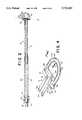
- FIG. 1is a perspective view of an electrosurgical instrument in accordance with a preferred embodiment of the present invention, shown attached to a bipolar generator and ready for use;
- FIG. 2is a transverse sectional view of an electrosurgical instrument in accordance with another preferred embodiment of the present invention, prior to removal of its protective electrode tip guard;
- FIG. 3is an exploded perspective view of the instrument of FIG. 2;
- FIG. 4is an enlarged perspective view of electrodes used in an electrode tip for the instrument in FIG. 1;
- FIG. 5is an enlarged top plan view of the electrode tip in FIG. 4 with a tip mounting superimposed thereon in phantom;
- FIG. 6is an enlarged sectional view of the electrode tip in FIG. 4, taken through line 6--6 of FIG. 4;
- FIG. 7is a blank of metal showing an electrode tip pattern for making an electrode tip for the instrument in FIG. 2;
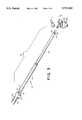
- FIG. 8shows a plurality of electrode tips for the instrument of FIG. 2, simultaneously formed from a single metal blank, and prior to being detached therefrom.
- FIG. 1shows an electrosurgical instrument 10 in accordance with a preferred embodiment of the present invention connected to a radio frequency (RF) output of a bipolar generator 12.
- Bipolar generatorsare well-known in the prior art, and thus are not described in detail herein.
- One bipolar generator suitable for use with the instrument 10is a CMC III bipolar generator, manufactured by Valley Forge Scientific Corp., Oaks, Pa., described in U.S. Pat. No. 5,318,563 (Malis et al.).
- FIG. 2shows internal structure of an instrument 10' and
- FIG. 3shows an exploded view of the main components of the instrument 10'.
- the instrument 10 shown in FIG. 1differs in two minor ways from the instrument 10' shown in FIGS. 2 and 3.
- the instrument 10'includes a guard 26 integrally formed with the tip of the instrument 10'.
- the guard 26is removed before use. In FIG. 1, the guard 26 has already been removed.
- the guard 26is described in more detail below.
- the instrument 10 shown in FIG. 1includes optional irrigation means, whereas the instrument 10' shown in FIGS. 2 and 3 does not include irrigation means. For clarity, FIGS. 1-3 are described together.
- the instruments 10 and 10'include a handle 14 and an electrode tip 16.
- the handle 14has a proximal end 18 and a distal end 20.
- the electrode tip 16extends from the distal end 20.
- the electrode tip 16includes a "working portion” which is generally forward of imaginary line 1 and a “non-working portion” or base portion which is generally behind the imaginary line 1 (see FIGS. 1 and 3).
- the "working portion”comprises that area of the electrode tip 16 which may contact a patient to cut or coagulate.
- the handle 14 in FIG. 1is constructed of integrally joined proximal and distal portions 22 and 24 of a high-impact polymeric tubing material, such as extruded styrene.
- the distal portion 24partially telescopes into the proximal portion 22 and is secured thereto with adhesive, such as epoxy or cyanoacrylate.
- the handle 14may be constructed as a unitary piece.
- the handle 14may optionally have circular spaced ribs (not shown) for enhanced gripping.
- the electrode tip 16includes a pair of conductive metal electrodes, an outer electrode 30 and an inner electrode 32, both of which include a portion which extends from the distal end 20 of the handle 14.
- the structure of the electrodes 30 and 32is described in more detail below. However, FIG. 3 (and also FIG. 4) clearly shows that the outer and inner electrodes 30 and 32 are not physically connected to each other and thus some means are required for maintaining a desired spacing therebetween.
- a T-shaped tip mounting 33(FIG. 1) of nonconductive material maintains the outer and inner electrodes 30 and 32 a fixed distance from each other and physically secures the electrode tip 16 to the distal end of the handle 14.
- FIG. 3shows that the tip mounting 33 is formed from two identical T-shaped pieces of nonconductive material 33a and 33b, portions of the electrode tip 16 being sandwiched therebetween. That is, portions of the electrode tip 16 are encased within the tip mounting 33.
- the imaginary line 1is colinear with the front edge of the tip mounting 33.
- each of the electrodes 30 and 32are connected to one end of a respective insulated conductor which extends through the handle 14 from the proximal end 18 to near the distal end 20.
- the electrode 30is connected to one end of a first insulated conductor 34 and the electrode 32 is connected to one end of a second insulated conductor 36.
- the other ends of the first and second conductors 34 and 36terminate in respective connection pins 38 and 40.
- the insulation on opposite ends of the conductors 34 and 36is removed to electrically connect the conductors 34 and 36 to the electrodes 30 and 32 at one end, and to the pins 38 and 40 at the other end.
- conductive wires 42 and 44are connected at one of their ends to the connection pins 38 and 40, respectively, and are connected at the other of their ends to opposite poles of an isolated output 48 of the bipolar generator 12.
- the instruments 10 and 10'each include an end cap 46 and 46', respectively, for sealing the proximal end 18 of the handle tubing and for supporting the connection pins 38 and 40.
- the end cap 46 of the instrument 10includes additional structure to support an irrigation tube associated with the irrigation means, as described below.
- an optional irrigation fluid tube 50extends through the handle 12 for delivering irrigation fluid to the surgical site.
- One end of the fluid tube 50is connected to a luer adapter (not shown) inside of the end cap 46.
- the other endpreferably terminates at the distal edge of the tip mounting 33, preferably extending about 1/16" beyond the tip mounting surface.
- the fluid tube 50enters the tubular handle 14 through an inlet port 52 near the proximal end 18, and exits the handle 14 through an outlet port 56 near the distal end 20 (which, when the instrument 10 is in use, is near the surgical site).
- the end cap 46includes an extension 47 with a bore for supporting the irrigation tube 50 at the end of the handle 10.
- the lueris inside of the extension 47.
- Irrigation tubing 51is connected at one end to the luer and at the other end to a source of irrigation fluid (not shown). Irrigation fluid (e.g., saline) from the fluid source is thus delivered through the tubing 51, luer, and tube 50 to the surgical site.
- Irrigation fluide.g., saline
- the pieces of material 33a and 33bare plate-like pieces of polymeric material, ultrasonically bonded to each other, to firmly hold the electrodes 30 and 32 in a fixed position with respect to each other.
- the pieces of material 33a and 33bmay be cast ceramic material held together with adhesive.
- the pieces of material 33a and 33bform a tip mounting 33.
- the distal end 20 of the handle 14is heated to a pliable state.
- the vertical portion of the tip mounting 33is inserted into the distal end 20. As the distal end 20 cools, it conforms to and grips the vertical portion of the tip mounting 33.
- the bondmay be further strengthened with adhesive, such as epoxy or cyanoacrylate.
- the electrode tip 16is secured to a handle without using the tip mounting 33.
- the handleis longitudinally divided into an upper half and lower half. The portions of the electrode tip 16 behind the imaginary line 1 are seated into grooves formed in the lower half of the handle, and terminal ends of the two electrodes make positive electrical connection to respective ends of the conductors 34 and 36.
- the upper half of the handleis placed over the lower half and secured thereto. The electrode tip 16 is thus held in place by being partially seated into the grooves and sandwiched between the upper and lower halves of the handle.
- Other means for securing the electrode tip 16 to the handleare within the scope of the invention.
- FIGS. 4-6show additional details and parameters of the electrode tip 16, absent the guard 26 and tip mounting 33.
- the tip mounting 33is superimposed on the electrode tip 16 in phantom.
- the electrode tip 16has a working portion and a base portion.
- each of the electrodes 30 and 32includes a working portion and a base portion.
- the working portions of each electrodeinclude the exposed loop parts of the electrodes (i.e., the portions of the electrodes 30 and 32 which are external to the tip mounting 33 and forward of the imaginary line 1).
- the remaining parts one the electrodes 30 and 32define the base portion.
- the electrode 30includes a working portion 80 and a base portion 82
- the electrode 32includes a working portion 84 and a base portion 86.
- the base portion 86comprises a horizontal section 94 and a lead or vertical section 92.
- the horizontal section 94bridges opposite ends of the looped working portion 84.
- the vertical section 92is connected at one end to the horizontal section 94.
- the free end of the vertical section 92is electrically connected to conductor 36, as shown in FIGS. 2 and 3.
- the working portion 84 and horizontal section 94define a closed loop.
- the base portion 82 of electrode 32comprises L-shaped sections 90 and 91 extending from opposite ends of the looped working portion 80.
- the L-shaped section 90includes a horizontal section 96 and vertical section 97.
- the L-shaped section 91also includes a horizontal section 98 and vertical section 99.
- the horizontal section 96is connected at one end to an end of the looped working portion 80, and at the other end to the vertical section 97.
- the free end of the vertical section 97is used to secure the electrode 30 in proper registration with the electrode 32 via the tip mounting 33 and to inhibit horizontal movement of the electrode 30 within the tip mounting 33.
- the horizontal section 98is connected at one end to the other end of the looped working portion 80, and at the other end to the vertical section 99.
- the free end of the vertical section 99is electrically connected to conductor 34, as shown in FIGS. 2 and 3.
- the horizontal sections 96 and 98 and the working portion 80define an almost closed loop which generally surrounds the closed loop of the electrode 30.
- the horizontal sections 96 and 98 and the working portion 80may be viewed as defining a hook shape which hooks almost completely around the closed loop of the electrode 32. Since the two electrodes 30 and 32 are coplanar and cannot come into electrical contact with each other, the electrode 30 cannot, by design, form a closed loop completely around the electrode 32.
- FIG. 5shows a top plan view of the electrode tip 16 in FIG. 4.
- FIG. 5also shows regions of the two electrodes 30 and 32 which are encased within the tip mounting 33, shown in phantom.
- the electrode 30generally surrounds the electrode 32 and is generally spaced from and coplanar with the electrode 32. More precisely, either all or at least a part of the working portion 80 of the electrode 30 surrounds either all or at least a part of the working portion 84 of the electrode 32. In FIG. 5, the entire working portion 80 surrounds the entire working portion 84. As also described above, there is a predetermined distance between the electrodes 30 and 32.
- the predetermined distance or spacing, sis generally equal along the entire path or shape of the electrodes 30 and 32.
- the spacing sis equal between the working portions 80 and with different spacings allowed between the base portions 82 and 94.
- there is always some finite spacing between the electrodes 30 and 32i.e., s>0
- the spacing s between the working portions 80 and 84 of the electrodes 30 and 32is equal, it can be said that the electrode 30 is equidistant from the electrode 32.
- the spacing sis equal along the entire path of the electrodes 30 and 32.
- the scope of the inventionalso includes embodiments wherein the spacing s between the working portions 80 and 84 of the electrodes 30 and 32 is unequal.
- the spacing s near the apex of the arc defined by the working portionsmay be different than the spacing s near the edge regions of the working portions. It may be desirable to have greater or less spacing s near the apex of the arc defined by the working portions than near the edge regions of the working portions.
- the electrode tip 16 and electrodes 30 and 32have defined dimensions and parameters.
- the tip mounting 33is shown in FIG. 5 because certain dimensions of the electrode tip 16 are defined in relationship to the tip mounting 33, or to other structure that performs the same function as the tip mounting 33.
- the maximum horizontal distance of the electrode tip 16is defined as the width, w t , of the working portion 84 of the electrode 32.
- the width, w tis the distance between opposite exposed ends of the working portion 84 of the electrode 32.
- the height of the electrode tip 16is defined as the height, h t , from the opposite exposed ends of the working portion 84 of the electrode 32 to apex 100 of the arc in the working portion 84 of the electrode 32.
- the electrode tip 16also has a loop ratio, defined as the ratio of the absolute distance of the working portion 84 vs. the absolute distance of the working portion 80.
- the leads or vertical sections 98 and 92have predefined lengths l e1 and l e2 , respectively.
- the working portion 80 of the electrode 30has a flat upper surface 102, a flat lower surface 104, and squared off sharp corners or edges 106.
- the working portion 84 of the electrode 32has a flat upper surface 108, a flat lower surface 110, and squared off sharp corners or edges 112.
- the base portions 82 and 86also have flat upper and lower surfaces, and sharp edges, due to the method of fabricating the electrodes 30 and 32. The base portions 82 and 86 need not have either of these features.
- the working portions 80 and 84are circumferentially unattached to any surrounding structure, and the material of the electrodes 30 and 32 is continuous (i.e., unbroken) through their respective working portions 84 and 80.
- at least the working portions 80 and 84 of the electrodes 30 and 32are generally rectangular in cross-section and thus are defined by a thickness and a width.
- the area of the rectangular cross-sectionis generally uniform throughout the working portion. Since the electrodes 30 and 32 are coplanar, they have equal thicknesses, t e .
- the widths of the electrode working portions 80 and 84may be equal or different. In the figures, the electrodes 30 and 32 have different working portion widths w e1 and w e2 , respectively. Widths of the horizontal sections 94, 96 and 98, and the leads or vertical sections 92 and 99 are significantly larger than the widths of the working portion 80 and 84.
- a preferred embodiment of the electrode tip 16has the following approximate range of dimensions and parameters:
- FIGS. 4-6show a 20 ⁇ 10 mm. tip having a thickness of about 0.015" (0.38 mm.).
- One preferred method of fabricating the electrode tip 16is by photo chemical machining.
- the processbegins with a metal blank 114, such as stainless steel, having a thickness t e and flat upper and lower surfaces 116 and 118.
- the metal blank 114is precoated with photoresist materials of common usage.
- a pattern 120 and its mirror image 120'are created by standard drafting techniques and are photographically transferred (in negative form) to transparent film.
- the patterns 120 and 120'may also be reduced in size to reduce drawing line widths and to achieve proper final product size.
- properly sized patterns 120 and 120'are placed in contact with respective upper and lower surfaces 116 and 118 of the metal blank 114, in proper registration and alignment with each other.
- the pattern 120 on the upper surface 116is in solid lines and the pattern 120' on the lower surface 118 is in phantom.
- the upper and lower patterns 120 and 120'are held closely to the metal blank 114 while an arc lamp 121 exposes the photoresist in the area where the negative patterns are transparent.
- the metal blank 114is removed and developed in the same manner as a negative photograph is developed. The developing process chemically hardens the photoresist in areas exposed to the arc lamp 121. The unexposed and undeveloped photoresist is washed away.
- the metal blank 114is exposed to chemicals commonly used in the art to dissolve metal not covered with photoresist.
- etch chemicalsmay be used. After etching, the remaining metal is a faithful reproduction, in metal, of the pattern 120, including at least the electrodes, a carrier and a protective guard structure, and support and tab structures, all for use during post-manufacturing handling.
- FIG. 7does not show the patterns which form the additional non-electrode structures. These patterns are shown in FIG. 8.
- the resultant piece of metalhas the shape of the created pattern, and is thus identical to FIGS. 4 and 5. That is, the resultant piece of metal is the shape of the electrodes 30 and 32. Since the metal blank 114 has flat upper and lower surfaces 116 and 118, the resultant electrodes 30 and 32 are coplanar and have sharp edges in cross-section.
- the resultant electrode tip 16i.e., electrodes 30 and 32
- the electrode tip 16is very delicate and should be protected from physical contact until it is ready to be used. Also, the relative registration of the electrodes 30 and 32 must be maintained because the two electrodes are not physically connected to each other at any point. To protect the electrode tip 16 and to maintain proper relative registration between the electrodes 30 and 32, it is preferred to fabricate the electrode tip 16 with a guard, supports, a carrier and tabs therebetween, and to install the tip mounting 33 after fabrication but before removal of the supports 124 or guard 26.
- electrode tips 16are made by the process described above, plural electrode tips 16 of the same or different width and height combinations may be simultaneously fabricated from a single metal blank. Thus, significant manufacturing efficiencies can be achieved.
- FIG. 8shows eight electrode tips 16 1 through 16 8 fabricated from a single metal blank 115 and illustrates all of these above-mentioned features.
- each electrode tip 16 1 through 16 8has a different width and height combination.
- a patternincluding (1) a peripheral carrier pattern, (2) an electrode pattern for each of the electrode tips 16 1 through 16 8 , and (3) associated support patterns, tab patterns and a guard pattern for each electrode pattern, is placed against both surfaces of the metal blank 115, as described above.
- the patternsform the electrode tips 16 1 through 16 8 , peripheral carrier 122, support plates or supports 124, guards 26 and tabs 128 in the resultant metal blank of FIG. 8.
- an electrode tip 16 and corresponding supports 124 and guard 26is removed from the carrier 122.
- non-working portions of the electrode tip 16are sandwiched between the two T-shaped pieces of material 33a and 33b.
- the pieces of material 33a and 33bare secured to each other and to the electrode tip 16, such as by ultrasonic bonding to form the tip mounting 33.
- the non-working portions of the electrode tip 16may be sandwiched between the two T-shaped pieces of material 33a and 33b while the electrode tip 16 is still in the carrier 122.
- the tip mounting 33encases all but the working portion of the electrode tip 16 and the terminal ends of each individual electrode.
- the tip mounting 33maintains relative registration of the working portions of the two electrodes.
- the supports 124 and related tabs 128are removed.
- One end of the first and second conductors 34 and 36are connected to respective terminal ends of the electrodes 30 and 32, such as by soldering or welding.
- the conductors 34 and 36are fitted through the distal portion of the handle 14.
- the electrode tip 16, with the guard 26 still intact,is then installed into the distal end of the distal portion 24 of the handle 14, in accordance with the procedure described above with respect to FIGS. 1-3.
- FIG. 2shows one such guard 26 attached to the electrode tip 16 of a fully assembled instrument 10. Immediately before use, the guard 26 is snapped off.
- the methodmay be used to separately fabricate each electrode 30 and 32.
- the photo chemical etching processmay be replaced by other processes which can achieve a similar result from a metal blank.
- Other potential techniquesinclude laser cutting, mechanical microcutting techniques or other techniques which can form electrodes having sharp edges and working portion dimensions defined above.
- the tipsmay be colored to quickly identify different sized electrodes.
- titanium electrodes tipsmay be colored by anodizing.
- Electrode tip sizesare selected according to the desired application (e.g., neurosurgery, obstetrics/gynecology surgery) and structure of the surgical site. For example, a long, narrow tip should be used when the surgical site is a narrow cavity.
- the guard 26may be replaced by other guard structure which need not be integrally formed with the electrode tip 16. It is also within the scope of the invention to make the electrodes 30 and 32 without the carrier 122, supports 124, guards 26 and tabs 128. Instead, the electrodes 30 and 32 may be carefully handled after fabrication and secured in a fixed relationship to each other, and to a handle, by other suitable means.
- the instrument 10is meant to be disposable, although it is within the scope of the invention to reuse any parts of the instrument 10 which are not degraded during use and which can be adequately sterilized.
- the loop shaped working portion of the electrodes 30 and 32may be generally circular, semicircular, parabolic or rectangular in shape.
- the electrodes 30 and 32 in the present instrumenthave sharp edges 106 and 112 in cross-section, in contrast to prior art wire electrodes which do not have sharp edges in cross-section.
- the sharp edgesconcentrate the contact area and improve the concentration of energy at the surgical site in comparison to the wire electrodes.
- energydistributes evenly along the length of the electrode working portions 80 and 82.
- the energyalso emits radially from the working portions 80 and 82.
- the emitted RF energyconcentrates and focuses at the edges 106 and 112 instead of radially emitting equally in all directions as in prior art wire electrodes. For at least this reason, the electrodes 30 and 32 formed by the process described above evidence lower resistance to cutting than the prior art wire electrodes.
- the devicecan be used in delicate surgical procedures, such as neurosurgery, with less risk of disturbing neighboring tissue or organs.
- the electrodes 30 and 32may be fabricated to be significantly finer than what is currently achievable using wire electrodes.
- the electrodes 30 and 32are ideally rectangular in cross-section. However, it is difficult to produce perfectly rectangular shaped electrodes using the chemical etching process described herein.
- the fabricated electrodesmay have regions of slight concavity along the side edges, giving a slightly hourglass shape to the electrodes in cross-section.
- Such electrodesstill possess the advantages described above because they still have relatively sharp edges.
- One way to minimize the concavity when etching from one side onlyis to etch about halfway through the blank, and then turn the blank over and etch through the other side.
Landscapes
- Health & Medical Sciences (AREA)
- Surgery (AREA)
- Engineering & Computer Science (AREA)
- Life Sciences & Earth Sciences (AREA)
- Biomedical Technology (AREA)
- Otolaryngology (AREA)
- Nuclear Medicine, Radiotherapy & Molecular Imaging (AREA)
- Plasma & Fusion (AREA)
- Physics & Mathematics (AREA)
- Heart & Thoracic Surgery (AREA)
- Medical Informatics (AREA)
- Molecular Biology (AREA)
- Animal Behavior & Ethology (AREA)
- General Health & Medical Sciences (AREA)
- Public Health (AREA)
- Veterinary Medicine (AREA)
- Surgical Instruments (AREA)
Abstract
Description
______________________________________ spacing, (s) 0.035" (0.89 mm.) width of electrode tip (w.sub.t) 0.20" to 0.98" (5 mm. to 25 mm.) height of electrode tip (h.sub.t) 0.20" to 0.59" (5 mm. to 15 mm.) length of vertical section 99 (l.sub.e1) 0.50" (12.7 mm.) length of vertical section 92 (l.sub.e2) 0.54" (13.6 mm.) loop ratio 1:11/2 thickness of electrodes (t.sub.e) 0.005" to 0.015" (0.13 mm. to 0.38 mm.) width of electrode 30 (w.sub.e1) 0.009" (0.23 mm.) width of electrode 32 (w.sub.e2) 0.006" (0.15 mm.) width ofhorizontal sections 90, 0.059" (1.5 mm.) 94 and 96 width of92 and 98 0.039" (1.0 mm.) vertical sections 30 and 32 material stainless steel, tungsten, titanium, tungsten deposited on stainless steel, INCONEL, (a nickel and chromium alloy) or other metallic alloys ______________________________________ electrode
Claims (44)
Priority Applications (2)
| Application Number | Priority Date | Filing Date | Title |
|---|---|---|---|
| US08/658,429US5733283A (en) | 1996-06-05 | 1996-06-05 | Flat loop bipolar electrode tips for electrosurgical instrument |
| US08/979,318US5855061A (en) | 1996-06-05 | 1997-11-26 | Method of making flat loop bipolar electrode tips for electrosurgical instrument |
Applications Claiming Priority (1)
| Application Number | Priority Date | Filing Date | Title |
|---|---|---|---|
| US08/658,429US5733283A (en) | 1996-06-05 | 1996-06-05 | Flat loop bipolar electrode tips for electrosurgical instrument |
Related Child Applications (1)
| Application Number | Title | Priority Date | Filing Date |
|---|---|---|---|
| US08/979,318DivisionUS5855061A (en) | 1996-06-05 | 1997-11-26 | Method of making flat loop bipolar electrode tips for electrosurgical instrument |
Publications (1)
| Publication Number | Publication Date |
|---|---|
| US5733283Atrue US5733283A (en) | 1998-03-31 |
Family
ID=24641212
Family Applications (2)
| Application Number | Title | Priority Date | Filing Date |
|---|---|---|---|
| US08/658,429Expired - LifetimeUS5733283A (en) | 1996-06-05 | 1996-06-05 | Flat loop bipolar electrode tips for electrosurgical instrument |
| US08/979,318Expired - LifetimeUS5855061A (en) | 1996-06-05 | 1997-11-26 | Method of making flat loop bipolar electrode tips for electrosurgical instrument |
Family Applications After (1)
| Application Number | Title | Priority Date | Filing Date |
|---|---|---|---|
| US08/979,318Expired - LifetimeUS5855061A (en) | 1996-06-05 | 1997-11-26 | Method of making flat loop bipolar electrode tips for electrosurgical instrument |
Country Status (1)
| Country | Link |
|---|---|
| US (2) | US5733283A (en) |
Cited By (55)
| Publication number | Priority date | Publication date | Assignee | Title |
|---|---|---|---|---|
| US5919189A (en)* | 1996-05-21 | 1999-07-06 | Benderev; Theodore V. | Electrosurgical instrument and method of use |
| US6030384A (en)* | 1998-05-01 | 2000-02-29 | Nezhat; Camran | Bipolar surgical instruments having focused electrical fields |
| US6123701A (en)* | 1997-10-09 | 2000-09-26 | Perfect Surgical Techniques, Inc. | Methods and systems for organ resection |
| US6136014A (en)* | 1998-09-01 | 2000-10-24 | Vivant Medical, Inc. | Percutaneous tissue removal device |
| US6306135B1 (en)* | 1999-11-22 | 2001-10-23 | Alan G. Ellman | Forehead lift suction probe |
| US6352533B1 (en) | 1999-05-03 | 2002-03-05 | Alan G. Ellman | Electrosurgical handpiece for treating tissue |
| US20020052601A1 (en)* | 1997-05-30 | 2002-05-02 | Goldberg S. Nahum | System and method for performing plate type radiofrequency ablation |
| WO2001049194A3 (en)* | 1999-12-30 | 2002-05-10 | Pearl Technology Holdings Llc | Face-lifting device |
| US6416513B1 (en)* | 2000-10-12 | 2002-07-09 | Scott Dresden | Configurable electrode instrument for use in loop electrical excision procedures |
| US6471709B1 (en) | 1998-10-30 | 2002-10-29 | Vivant Medical, Inc. | Expandable ring percutaneous tissue removal device |
| US20020165541A1 (en)* | 2001-04-20 | 2002-11-07 | Whitman Michael P. | Bipolar or ultrasonic surgical device |
| US6514252B2 (en) | 1998-05-01 | 2003-02-04 | Perfect Surgical Techniques, Inc. | Bipolar surgical instruments having focused electrical fields |
| US20030130655A1 (en)* | 1995-06-07 | 2003-07-10 | Arthrocare Corporation | Electrosurgical systems and methods for removing and modifying tissue |
| US20030216725A1 (en)* | 1993-05-10 | 2003-11-20 | Arthrocare Corporation | Electrosurgical apparatus and methods for laparoscopy |
| US6743228B2 (en) | 2001-09-12 | 2004-06-01 | Manoa Medical, Inc. | Devices and methods for tissue severing and removal |
| US20040167431A1 (en)* | 1998-03-03 | 2004-08-26 | Burbank Fred H. | Breast biopsy system and methods |
| US20050131402A1 (en)* | 2001-02-09 | 2005-06-16 | Arthrocare Corporation | Electrosurgical probe with movable return electrode and methods related thereto |
| US20050187489A1 (en)* | 1998-03-03 | 2005-08-25 | Wardle John L. | Electrosurgical specimen-collection system |
| US20050283149A1 (en)* | 2004-06-08 | 2005-12-22 | Thorne Jonathan O | Electrosurgical cutting instrument |
| US20050284481A1 (en)* | 2004-06-23 | 2005-12-29 | Dragerwerk Aktiengesellschaft | Breathing mask with breathing gas supply through the strap |
| US20060095031A1 (en)* | 2004-09-22 | 2006-05-04 | Arthrocare Corporation | Selectively controlled active electrodes for electrosurgical probe |
| US20060129145A1 (en)* | 1997-10-23 | 2006-06-15 | Arthrocare Corporation | Bipolar electrosurgical clamp for removing and modifying tissue |
| US20060271041A1 (en)* | 2005-05-12 | 2006-11-30 | Joseph Eder | Method for Tissue Cauterization |
| US20060271037A1 (en)* | 2005-05-25 | 2006-11-30 | Forcept, Inc. | Assisted systems and methods for performing transvaginal hysterectomies |
| US20070005061A1 (en)* | 2005-06-30 | 2007-01-04 | Forcept, Inc. | Transvaginal uterine artery occlusion |
| US20070027450A1 (en)* | 2005-07-28 | 2007-02-01 | Forcept, Inc. | Devices and methods for mobilization of the uterus |
| US20070034211A1 (en)* | 2003-06-17 | 2007-02-15 | Bernhard Hug | Electrosurgical instrument for an endoscopre or a catheter |
| US20070129726A1 (en)* | 2005-05-12 | 2007-06-07 | Eder Joseph C | Electrocautery method and apparatus |
| USD547867S1 (en) | 2006-04-17 | 2007-07-31 | Synergetics Usa, Inc. | Surgical instrument handle |
| US20070213711A1 (en)* | 2006-03-08 | 2007-09-13 | Joseph Eder | Method and apparatus for surgical electrocautery |
| US20070265613A1 (en)* | 2006-05-10 | 2007-11-15 | Edelstein Peter Seth | Method and apparatus for sealing tissue |
| US20080004619A1 (en)* | 2006-06-28 | 2008-01-03 | Synergetics Usa, Inc. | Electrosurgical bipolar instrument |
| USD560278S1 (en) | 2005-09-27 | 2008-01-22 | Synergetics Usa, Inc. | Electrosurgical bipolar cutting/coagulating instrument |
| US20080172052A1 (en)* | 2006-05-02 | 2008-07-17 | Joseph Eder | Surgical Tool |
| US20080281323A1 (en)* | 1999-01-27 | 2008-11-13 | Burbank Fred H | Tissue specimen isolating and damaging device and method |
| US20090163905A1 (en)* | 2007-12-21 | 2009-06-25 | Winkler Matthew J | Ablation device with internally cooled electrodes |
| US20090198272A1 (en)* | 2008-02-06 | 2009-08-06 | Lawrence Kerver | Method and apparatus for articulating the wrist of a laparoscopic grasping instrument |
| EP1729657A4 (en)* | 2004-03-31 | 2010-09-29 | Manoa Medical Inc | Tissue cutting devices and methods |
| USD629100S1 (en)* | 2009-07-14 | 2010-12-14 | Karl Storz Gmbh & Co. Kg | Bipolar electrode |
| US20110144729A1 (en)* | 1998-05-28 | 2011-06-16 | Paul Joseph Weber | Facial tissue strengthening and tightening device and methods |
| US20110230875A1 (en)* | 2008-02-06 | 2011-09-22 | Erik Walberg | Articulable electrosurgical instrument with a stabilizable articulation actuator |
| US20110238062A1 (en)* | 2010-03-26 | 2011-09-29 | Tim Koss | Impedance Mediated Power Delivery for Electrosurgery |
| US20110238056A1 (en)* | 2010-03-26 | 2011-09-29 | Tim Koss | Impedance mediated control of power delivery for electrosurgery |
| US20120029514A1 (en)* | 2009-04-10 | 2012-02-02 | Fairbourn David C | Silane coating for medical devices and associated methods |
| US8728072B2 (en) | 2005-05-12 | 2014-05-20 | Aesculap Ag | Electrocautery method and apparatus |
| US8998892B2 (en) | 2007-12-21 | 2015-04-07 | Atricure, Inc. | Ablation device with cooled electrodes and methods of use |
| US9173698B2 (en) | 2010-09-17 | 2015-11-03 | Aesculap Ag | Electrosurgical tissue sealing augmented with a seal-enhancing composition |
| US9216012B2 (en) | 1998-09-01 | 2015-12-22 | Senorx, Inc | Methods and apparatus for securing medical instruments to desired locations in a patient's body |
| US9339323B2 (en) | 2005-05-12 | 2016-05-17 | Aesculap Ag | Electrocautery method and apparatus |
| US9339327B2 (en) | 2011-06-28 | 2016-05-17 | Aesculap Ag | Electrosurgical tissue dissecting device |
| US20180014875A1 (en)* | 2016-07-15 | 2018-01-18 | I.C. Medical, Inc. | Ultrapolar telescopic electrosurgery pencil |
| US9872724B2 (en) | 2012-09-26 | 2018-01-23 | Aesculap Ag | Apparatus for tissue cutting and sealing |
| US9918778B2 (en) | 2006-05-02 | 2018-03-20 | Aesculap Ag | Laparoscopic radiofrequency surgical device |
| WO2020117723A1 (en)* | 2018-12-04 | 2020-06-11 | Stanley Ii Robert James | Electrosurgical electrodes and systems and methods including same |
| US11051872B2 (en) | 2017-12-04 | 2021-07-06 | II Robert James Stanley | Electrosurgical electrodes and systems and methods including same |
Families Citing this family (13)
| Publication number | Priority date | Publication date | Assignee | Title |
|---|---|---|---|---|
| US6699244B2 (en) | 1997-02-12 | 2004-03-02 | Oratec Interventions, Inc. | Electrosurgical instrument having a chamber to volatize a liquid |
| US6358273B1 (en) | 1999-04-09 | 2002-03-19 | Oratec Inventions, Inc. | Soft tissue heating apparatus with independent, cooperative heating sources |
| US6773432B1 (en) | 1999-10-14 | 2004-08-10 | Applied Medical Resources Corporation | Electrosurgical snare |
| US20040260281A1 (en)* | 2002-09-19 | 2004-12-23 | Baxter Chester O. | Finger tip electrosurgical medical device |
| US9191799B2 (en)* | 2006-06-09 | 2015-11-17 | Juniper Networks, Inc. | Sharing data between wireless switches system and method |
| US9131977B2 (en) | 2009-04-17 | 2015-09-15 | Domain Surgical, Inc. | Layered ferromagnetic coated conductor thermal surgical tool |
| US9107666B2 (en) | 2009-04-17 | 2015-08-18 | Domain Surgical, Inc. | Thermal resecting loop |
| US9730749B2 (en) | 2009-04-17 | 2017-08-15 | Domain Surgical, Inc. | Surgical scalpel with inductively heated regions |
| US8920417B2 (en)* | 2010-06-30 | 2014-12-30 | Medtronic Advanced Energy Llc | Electrosurgical devices and methods of use thereof |
| US8906012B2 (en)* | 2010-06-30 | 2014-12-09 | Medtronic Advanced Energy Llc | Electrosurgical devices with wire electrode |
| WO2013040255A2 (en) | 2011-09-13 | 2013-03-21 | Domain Surgical, Inc. | Sealing and/or cutting instrument |
| JP2015506729A (en) | 2011-12-06 | 2015-03-05 | ドメイン・サージカル,インコーポレーテッド | System and method for controlling power supply to a surgical instrument |
| US10357306B2 (en)* | 2014-05-14 | 2019-07-23 | Domain Surgical, Inc. | Planar ferromagnetic coated surgical tip and method for making |
Citations (78)
| Publication number | Priority date | Publication date | Assignee | Title |
|---|---|---|---|---|
| US2377540A (en)* | 1941-02-12 | 1945-06-05 | Costa Alvaro Da Silva | Tonsillotome |
| US3234356A (en)* | 1963-05-07 | 1966-02-08 | Raymond F Babb | Electrically heated medical implement |
| US3526750A (en)* | 1967-06-02 | 1970-09-01 | William J Siegel | Thermal tool |
| US3647584A (en)* | 1970-01-05 | 1972-03-07 | Gregory A Duffy | Chemical milling process |
| US3679500A (en)* | 1970-08-07 | 1972-07-25 | Dainippon Screen Mfg | Method for forming perforations in metal sheets by etching |
| US3708295A (en)* | 1970-03-13 | 1973-01-02 | Ciba Geigy Ag | Process for the manufacture of metallic,electrically conductive patterns |
| US3738879A (en)* | 1970-03-19 | 1973-06-12 | Siemens Ag | Method of producing an exact edge on an etched article |
| US3813310A (en)* | 1972-10-02 | 1974-05-28 | Central City Micro Foundry Ltd | Method for the manufacture of flat costume jewelry |
| US3839108A (en)* | 1970-07-22 | 1974-10-01 | Us Navy | Method of forming a precision pattern of apertures in a plate |
| US3901242A (en)* | 1974-05-30 | 1975-08-26 | Storz Endoskop Gmbh | Electric surgical instrument |
| US3959527A (en)* | 1974-04-08 | 1976-05-25 | Lee John Droege | Flat costume jewelry and method for the surface treatment thereof |
| US3970088A (en)* | 1974-08-28 | 1976-07-20 | Valleylab, Inc. | Electrosurgical devices having sesquipolar electrode structures incorporated therein |
| DE2525982A1 (en)* | 1975-06-11 | 1976-12-16 | Wolf Gmbh Richard | DOUBLE OR SINGLE-END CUTTERING LOOP FOR RESECTOSCOPES |
| US4043342A (en)* | 1974-08-28 | 1977-08-23 | Valleylab, Inc. | Electrosurgical devices having sesquipolar electrode structures incorporated therein |
| US4051855A (en)* | 1976-02-06 | 1977-10-04 | Ipco Hospital Supply Corporation, Whaledent International Division | Electrosurgical unit |
| US4074718A (en)* | 1976-03-17 | 1978-02-21 | Valleylab, Inc. | Electrosurgical instrument |
| US4116198A (en)* | 1975-05-15 | 1978-09-26 | Delma, Elektro Und Medizinische Apparatebaugesellschaft M.B.H. | Electro - surgical device |
| US4161950A (en)* | 1975-08-01 | 1979-07-24 | The United States Of America As Represented By The United States Department Of Energy | Electrosurgical knife |
| US4202337A (en)* | 1977-06-14 | 1980-05-13 | Concept, Inc. | Bipolar electrosurgical knife |
| US4228800A (en)* | 1978-04-04 | 1980-10-21 | Concept, Inc. | Bipolar electrosurgical knife |
| US4232676A (en)* | 1978-11-16 | 1980-11-11 | Corning Glass Works | Surgical cutting instrument |
| US4248231A (en)* | 1978-11-16 | 1981-02-03 | Corning Glass Works | Surgical cutting instrument |
| US4269174A (en)* | 1979-08-06 | 1981-05-26 | Medical Dynamics, Inc. | Transcutaneous vasectomy apparatus and method |
| US4301802A (en)* | 1980-03-17 | 1981-11-24 | Stanley Poler | Cauterizing tool for ophthalmological surgery |
| US4380876A (en)* | 1980-11-07 | 1983-04-26 | W. R. Weaver Co. | Reticle and method of making the same |
| US4482426A (en)* | 1984-04-02 | 1984-11-13 | Rca Corporation | Method for etching apertures into a strip of nickel-iron alloy |
| US4532924A (en)* | 1980-05-13 | 1985-08-06 | American Hospital Supply Corporation | Multipolar electrosurgical device and method |
| US4548207A (en)* | 1982-11-17 | 1985-10-22 | Mentor O & O, Inc. | Disposable coagulator |
| US4578318A (en)* | 1984-10-17 | 1986-03-25 | Tamerlane Corporation | Sheet metal ornaments having a lacy appearance and process for making them |
| US4637392A (en)* | 1983-12-21 | 1987-01-20 | Kharkovsky Nauchno-Issledovatelsky Institut Obschei I Neotlozhnoi Khirurgii | Bipolar electrocoagulator |
| US4637390A (en)* | 1983-12-01 | 1987-01-20 | Nauchno-Issledovatelsky Institut Obschei i Neotlozhno Khirurgii | Electrosurgical instrument |
| US4651734A (en)* | 1985-02-08 | 1987-03-24 | The United States Of America As Represented By The United States Department Of Energy | Electrosurgical device for both mechanical cutting and coagulation of bleeding |
| US4674499A (en)* | 1980-12-08 | 1987-06-23 | Pao David S C | Coaxial bipolar probe |
| US4674498A (en)* | 1983-07-06 | 1987-06-23 | Everest Medical Corporation | Electro cautery surgical blade |
| US4684438A (en)* | 1984-02-03 | 1987-08-04 | Commissariat A L'energie Atomique | Process for producing a coil for a magnetic recording head |
| US4686980A (en)* | 1986-04-17 | 1987-08-18 | Alcon Laboratories, Inc. | Disposable bipolar instrument |
| US4706667A (en)* | 1984-06-25 | 1987-11-17 | Berchtold Medizin-Elektronik Gmbh & Co. | Electro surgical high frequency cutting instrument |
| US4711239A (en)* | 1985-01-25 | 1987-12-08 | Sorochenko Oleg A | Electrosurgical instrument |
| US4711800A (en)* | 1985-06-06 | 1987-12-08 | Divincenzo Maureen | Needlecraft with metallic substrate |
| DD252284A3 (en)* | 1987-12-16 | Bipolar biaktive electroagulator | ||
| DD257348A3 (en)* | 1984-03-13 | 1988-06-15 | Oleg A Sorocenko | ELECTRO-SURGICAL INSTRUMENT |
| US4765331A (en)* | 1987-02-10 | 1988-08-23 | Circon Corporation | Electrosurgical device with treatment arc of less than 360 degrees |
| EP0280972A1 (en)* | 1987-03-04 | 1988-09-07 | Siemens Aktiengesellschaft | Hand piece for a liquid-jet cutting apparatus |
| EP0294063A2 (en)* | 1987-06-01 | 1988-12-07 | Everest Medical Corporation | Electro-surgical instrument |
| US4805616A (en)* | 1980-12-08 | 1989-02-21 | Pao David S C | Bipolar probes for ophthalmic surgery and methods of performing anterior capsulotomy |
| US4818962A (en)* | 1985-09-03 | 1989-04-04 | Thomson-Csf | Waveguide obtained by selective etching method |
| US4823791A (en)* | 1987-05-08 | 1989-04-25 | Circon Acmi Division Of Circon Corporation | Electrosurgical probe apparatus |
| US4860745A (en)* | 1986-07-17 | 1989-08-29 | Erbe Elektromedizin Gmbh | High frequency electrosurgical apparatus for thermal coagulation of biologic tissues |
| US4862890A (en)* | 1988-02-29 | 1989-09-05 | Everest Medical Corporation | Electrosurgical spatula blade with ceramic substrate |
| US4876110A (en)* | 1987-02-24 | 1989-10-24 | American Medical Products, Inc. | Electrosurgical knife |
| US4905691A (en)* | 1989-04-17 | 1990-03-06 | Everest Medical Corporation | Polypectome snare with bipolar electrodes |
| US4922903A (en)* | 1988-10-06 | 1990-05-08 | Everest Medical Corporation | Handle for electro-surgical blade |
| US4936842A (en)* | 1987-05-08 | 1990-06-26 | Circon Corporation | Electrosurgical probe apparatus |
| US4936281A (en)* | 1989-04-13 | 1990-06-26 | Everest Medical Corporation | Ultrasonically enhanced RF ablation catheter |
| US5009656A (en)* | 1989-08-17 | 1991-04-23 | Mentor O&O Inc. | Bipolar electrosurgical instrument |
| US5013312A (en)* | 1990-03-19 | 1991-05-07 | Everest Medical Corporation | Bipolar scalpel for harvesting internal mammary artery |
| US5071419A (en)* | 1990-04-30 | 1991-12-10 | Everest Medical Corporation | Percutaneous laparoscopic cholecystectomy instrument |
| US5073233A (en)* | 1989-06-07 | 1991-12-17 | Ciba-Geigy Corporation | Method of making a metallic pattern on a substrate |
| US5084045A (en)* | 1990-09-17 | 1992-01-28 | Helenowski Tomasz K | Suction surgical instrument |
| US5089002A (en)* | 1989-04-06 | 1992-02-18 | Kirwan Surgical Products, Inc. | Disposable bipolar coagulator |
| US5120396A (en)* | 1991-06-04 | 1992-06-09 | Chen Kuo C | Process for forming a figure on a product of stainless steel |
| US5125927A (en)* | 1991-02-19 | 1992-06-30 | Belanger Neil F | Breakaway electrode for surgical cutting and cauterizing tool |
| US5171311A (en)* | 1990-04-30 | 1992-12-15 | Everest Medical Corporation | Percutaneous laparoscopic cholecystectomy instrument |
| US5192280A (en)* | 1991-11-25 | 1993-03-09 | Everest Medical Corporation | Pivoting multiple loop bipolar cutting device |
| US5197964A (en)* | 1991-11-12 | 1993-03-30 | Everest Medical Corporation | Bipolar instrument utilizing one stationary electrode and one movable electrode |
| WO1993013719A1 (en)* | 1992-01-15 | 1993-07-22 | Beacon Laboratories, Inc. | Bipolar electrosurgical instrument |
| US5269782A (en)* | 1991-04-22 | 1993-12-14 | Select Medizin-Technik Hermann Sutter Gmbh | Bipolar medical coagulation and cauterizing instrument |
| US5282799A (en)* | 1990-08-24 | 1994-02-01 | Everest Medical Corporation | Bipolar electrosurgical scalpel with paired loop electrodes |
| US5290285A (en)* | 1992-04-23 | 1994-03-01 | Kirwan Surgical Products, Inc. | Electrocautery device having two electrically active areas of the terminal end spaced from each other |
| US5302234A (en)* | 1993-01-28 | 1994-04-12 | Grace Manufacturing Inc. | Surgical cutting instrument forming method |
| US5318564A (en)* | 1992-05-01 | 1994-06-07 | Hemostatic Surgery Corporation | Bipolar surgical snare and methods of use |
| US5318563A (en)* | 1992-06-04 | 1994-06-07 | Valley Forge Scientific Corporation | Bipolar RF generator |
| US5317938A (en)* | 1992-01-16 | 1994-06-07 | Duke University | Method for making microstructural surgical instruments |
| US5354422A (en)* | 1991-03-12 | 1994-10-11 | Dai Nippon Printing Co., Ltd. | Process for producing leadframe material for semiconductor |
| US5437665A (en)* | 1993-10-12 | 1995-08-01 | Munro; Malcolm G. | Electrosurgical loop electrode instrument for laparoscopic surgery |
| US5451224A (en)* | 1992-02-27 | 1995-09-19 | G2 Design Limited | Apparatus for radio frequency bipolar electrosurgery |
| US5569244A (en)* | 1995-04-20 | 1996-10-29 | Symbiosis Corporation | Loop electrodes for electrocautery probes for use with a resectoscope |
| US5593406A (en)* | 1992-05-01 | 1997-01-14 | Hemostatic Surgery Corporation | Endoscopic instrument with auto-regulating heater and method of using same |
Family Cites Families (2)
| Publication number | Priority date | Publication date | Assignee | Title |
|---|---|---|---|---|
| US4649937A (en)* | 1985-01-28 | 1987-03-17 | Cordis Corporation | Etched grooved electrode for pacing lead and method for making same |
| JPH03123049A (en)* | 1989-10-05 | 1991-05-24 | Tokyo Electron Ltd | Electrode body |
- 1996
- 1996-06-05USUS08/658,429patent/US5733283A/ennot_activeExpired - Lifetime
- 1997
- 1997-11-26USUS08/979,318patent/US5855061A/ennot_activeExpired - Lifetime
Patent Citations (82)
| Publication number | Priority date | Publication date | Assignee | Title |
|---|---|---|---|---|
| DD252284A3 (en)* | 1987-12-16 | Bipolar biaktive electroagulator | ||
| US2377540A (en)* | 1941-02-12 | 1945-06-05 | Costa Alvaro Da Silva | Tonsillotome |
| US3234356A (en)* | 1963-05-07 | 1966-02-08 | Raymond F Babb | Electrically heated medical implement |
| US3526750A (en)* | 1967-06-02 | 1970-09-01 | William J Siegel | Thermal tool |
| US3647584A (en)* | 1970-01-05 | 1972-03-07 | Gregory A Duffy | Chemical milling process |
| US3708295A (en)* | 1970-03-13 | 1973-01-02 | Ciba Geigy Ag | Process for the manufacture of metallic,electrically conductive patterns |
| US3738879A (en)* | 1970-03-19 | 1973-06-12 | Siemens Ag | Method of producing an exact edge on an etched article |
| US3839108A (en)* | 1970-07-22 | 1974-10-01 | Us Navy | Method of forming a precision pattern of apertures in a plate |
| US3679500A (en)* | 1970-08-07 | 1972-07-25 | Dainippon Screen Mfg | Method for forming perforations in metal sheets by etching |
| US3813310A (en)* | 1972-10-02 | 1974-05-28 | Central City Micro Foundry Ltd | Method for the manufacture of flat costume jewelry |
| US3959527A (en)* | 1974-04-08 | 1976-05-25 | Lee John Droege | Flat costume jewelry and method for the surface treatment thereof |
| US3901242A (en)* | 1974-05-30 | 1975-08-26 | Storz Endoskop Gmbh | Electric surgical instrument |
| US3970088A (en)* | 1974-08-28 | 1976-07-20 | Valleylab, Inc. | Electrosurgical devices having sesquipolar electrode structures incorporated therein |
| US3987795A (en)* | 1974-08-28 | 1976-10-26 | Valleylab, Inc. | Electrosurgical devices having sesquipolar electrode structures incorporated therein |
| US4043342A (en)* | 1974-08-28 | 1977-08-23 | Valleylab, Inc. | Electrosurgical devices having sesquipolar electrode structures incorporated therein |
| US4116198A (en)* | 1975-05-15 | 1978-09-26 | Delma, Elektro Und Medizinische Apparatebaugesellschaft M.B.H. | Electro - surgical device |
| DE2525982A1 (en)* | 1975-06-11 | 1976-12-16 | Wolf Gmbh Richard | DOUBLE OR SINGLE-END CUTTERING LOOP FOR RESECTOSCOPES |
| US4060087A (en)* | 1975-06-11 | 1977-11-29 | Richard Wolf Gmbh | Single or double-shank cutting loop device for resectoscopes |
| US4161950A (en)* | 1975-08-01 | 1979-07-24 | The United States Of America As Represented By The United States Department Of Energy | Electrosurgical knife |
| US4051855A (en)* | 1976-02-06 | 1977-10-04 | Ipco Hospital Supply Corporation, Whaledent International Division | Electrosurgical unit |
| US4074718A (en)* | 1976-03-17 | 1978-02-21 | Valleylab, Inc. | Electrosurgical instrument |
| US4202337A (en)* | 1977-06-14 | 1980-05-13 | Concept, Inc. | Bipolar electrosurgical knife |
| US4228800A (en)* | 1978-04-04 | 1980-10-21 | Concept, Inc. | Bipolar electrosurgical knife |
| US4232676A (en)* | 1978-11-16 | 1980-11-11 | Corning Glass Works | Surgical cutting instrument |
| US4248231A (en)* | 1978-11-16 | 1981-02-03 | Corning Glass Works | Surgical cutting instrument |
| US4269174A (en)* | 1979-08-06 | 1981-05-26 | Medical Dynamics, Inc. | Transcutaneous vasectomy apparatus and method |
| US4301802A (en)* | 1980-03-17 | 1981-11-24 | Stanley Poler | Cauterizing tool for ophthalmological surgery |
| US4532924A (en)* | 1980-05-13 | 1985-08-06 | American Hospital Supply Corporation | Multipolar electrosurgical device and method |
| US4380876A (en)* | 1980-11-07 | 1983-04-26 | W. R. Weaver Co. | Reticle and method of making the same |
| US4674499A (en)* | 1980-12-08 | 1987-06-23 | Pao David S C | Coaxial bipolar probe |
| US4805616A (en)* | 1980-12-08 | 1989-02-21 | Pao David S C | Bipolar probes for ophthalmic surgery and methods of performing anterior capsulotomy |
| US4548207A (en)* | 1982-11-17 | 1985-10-22 | Mentor O & O, Inc. | Disposable coagulator |
| US4674498A (en)* | 1983-07-06 | 1987-06-23 | Everest Medical Corporation | Electro cautery surgical blade |
| US4637390A (en)* | 1983-12-01 | 1987-01-20 | Nauchno-Issledovatelsky Institut Obschei i Neotlozhno Khirurgii | Electrosurgical instrument |
| US4637392A (en)* | 1983-12-21 | 1987-01-20 | Kharkovsky Nauchno-Issledovatelsky Institut Obschei I Neotlozhnoi Khirurgii | Bipolar electrocoagulator |
| US4684438A (en)* | 1984-02-03 | 1987-08-04 | Commissariat A L'energie Atomique | Process for producing a coil for a magnetic recording head |
| DD257348A3 (en)* | 1984-03-13 | 1988-06-15 | Oleg A Sorocenko | ELECTRO-SURGICAL INSTRUMENT |
| US4482426A (en)* | 1984-04-02 | 1984-11-13 | Rca Corporation | Method for etching apertures into a strip of nickel-iron alloy |
| US4706667A (en)* | 1984-06-25 | 1987-11-17 | Berchtold Medizin-Elektronik Gmbh & Co. | Electro surgical high frequency cutting instrument |
| US4578318A (en)* | 1984-10-17 | 1986-03-25 | Tamerlane Corporation | Sheet metal ornaments having a lacy appearance and process for making them |
| US4711239A (en)* | 1985-01-25 | 1987-12-08 | Sorochenko Oleg A | Electrosurgical instrument |
| US4651734A (en)* | 1985-02-08 | 1987-03-24 | The United States Of America As Represented By The United States Department Of Energy | Electrosurgical device for both mechanical cutting and coagulation of bleeding |
| US4711800A (en)* | 1985-06-06 | 1987-12-08 | Divincenzo Maureen | Needlecraft with metallic substrate |
| US4818962A (en)* | 1985-09-03 | 1989-04-04 | Thomson-Csf | Waveguide obtained by selective etching method |
| US4686980A (en)* | 1986-04-17 | 1987-08-18 | Alcon Laboratories, Inc. | Disposable bipolar instrument |
| US4860745A (en)* | 1986-07-17 | 1989-08-29 | Erbe Elektromedizin Gmbh | High frequency electrosurgical apparatus for thermal coagulation of biologic tissues |
| US4765331A (en)* | 1987-02-10 | 1988-08-23 | Circon Corporation | Electrosurgical device with treatment arc of less than 360 degrees |
| US4876110A (en)* | 1987-02-24 | 1989-10-24 | American Medical Products, Inc. | Electrosurgical knife |
| EP0280972A1 (en)* | 1987-03-04 | 1988-09-07 | Siemens Aktiengesellschaft | Hand piece for a liquid-jet cutting apparatus |
| US4936842A (en)* | 1987-05-08 | 1990-06-26 | Circon Corporation | Electrosurgical probe apparatus |
| US4823791A (en)* | 1987-05-08 | 1989-04-25 | Circon Acmi Division Of Circon Corporation | Electrosurgical probe apparatus |
| EP0294063A2 (en)* | 1987-06-01 | 1988-12-07 | Everest Medical Corporation | Electro-surgical instrument |
| US4802476A (en)* | 1987-06-01 | 1989-02-07 | Everest Medical Corporation | Electro-surgical instrument |
| US4862890A (en)* | 1988-02-29 | 1989-09-05 | Everest Medical Corporation | Electrosurgical spatula blade with ceramic substrate |
| US4922903A (en)* | 1988-10-06 | 1990-05-08 | Everest Medical Corporation | Handle for electro-surgical blade |
| US5089002A (en)* | 1989-04-06 | 1992-02-18 | Kirwan Surgical Products, Inc. | Disposable bipolar coagulator |
| US4936281A (en)* | 1989-04-13 | 1990-06-26 | Everest Medical Corporation | Ultrasonically enhanced RF ablation catheter |
| US4905691A (en)* | 1989-04-17 | 1990-03-06 | Everest Medical Corporation | Polypectome snare with bipolar electrodes |
| US5073233A (en)* | 1989-06-07 | 1991-12-17 | Ciba-Geigy Corporation | Method of making a metallic pattern on a substrate |
| US5009656A (en)* | 1989-08-17 | 1991-04-23 | Mentor O&O Inc. | Bipolar electrosurgical instrument |
| US5013312A (en)* | 1990-03-19 | 1991-05-07 | Everest Medical Corporation | Bipolar scalpel for harvesting internal mammary artery |
| US5071419A (en)* | 1990-04-30 | 1991-12-10 | Everest Medical Corporation | Percutaneous laparoscopic cholecystectomy instrument |
| US5171311A (en)* | 1990-04-30 | 1992-12-15 | Everest Medical Corporation | Percutaneous laparoscopic cholecystectomy instrument |
| US5282799A (en)* | 1990-08-24 | 1994-02-01 | Everest Medical Corporation | Bipolar electrosurgical scalpel with paired loop electrodes |
| US5084045A (en)* | 1990-09-17 | 1992-01-28 | Helenowski Tomasz K | Suction surgical instrument |
| US5125927A (en)* | 1991-02-19 | 1992-06-30 | Belanger Neil F | Breakaway electrode for surgical cutting and cauterizing tool |
| US5354422A (en)* | 1991-03-12 | 1994-10-11 | Dai Nippon Printing Co., Ltd. | Process for producing leadframe material for semiconductor |
| US5269782A (en)* | 1991-04-22 | 1993-12-14 | Select Medizin-Technik Hermann Sutter Gmbh | Bipolar medical coagulation and cauterizing instrument |
| US5120396A (en)* | 1991-06-04 | 1992-06-09 | Chen Kuo C | Process for forming a figure on a product of stainless steel |
| US5197964A (en)* | 1991-11-12 | 1993-03-30 | Everest Medical Corporation | Bipolar instrument utilizing one stationary electrode and one movable electrode |
| US5290286A (en)* | 1991-11-12 | 1994-03-01 | Everest Medical Corporation | Bipolar instrument utilizing one stationary electrode and one movable electrode |
| US5192280A (en)* | 1991-11-25 | 1993-03-09 | Everest Medical Corporation | Pivoting multiple loop bipolar cutting device |
| WO1993013719A1 (en)* | 1992-01-15 | 1993-07-22 | Beacon Laboratories, Inc. | Bipolar electrosurgical instrument |
| US5317938A (en)* | 1992-01-16 | 1994-06-07 | Duke University | Method for making microstructural surgical instruments |
| US5451224A (en)* | 1992-02-27 | 1995-09-19 | G2 Design Limited | Apparatus for radio frequency bipolar electrosurgery |
| US5290285A (en)* | 1992-04-23 | 1994-03-01 | Kirwan Surgical Products, Inc. | Electrocautery device having two electrically active areas of the terminal end spaced from each other |
| US5318564A (en)* | 1992-05-01 | 1994-06-07 | Hemostatic Surgery Corporation | Bipolar surgical snare and methods of use |
| US5593406A (en)* | 1992-05-01 | 1997-01-14 | Hemostatic Surgery Corporation | Endoscopic instrument with auto-regulating heater and method of using same |
| US5318563A (en)* | 1992-06-04 | 1994-06-07 | Valley Forge Scientific Corporation | Bipolar RF generator |
| US5302234A (en)* | 1993-01-28 | 1994-04-12 | Grace Manufacturing Inc. | Surgical cutting instrument forming method |
| US5437665A (en)* | 1993-10-12 | 1995-08-01 | Munro; Malcolm G. | Electrosurgical loop electrode instrument for laparoscopic surgery |
| US5569244A (en)* | 1995-04-20 | 1996-10-29 | Symbiosis Corporation | Loop electrodes for electrocautery probes for use with a resectoscope |
Non-Patent Citations (2)
| Title |
|---|
| Brochure entitled "Photo Chemical Machining", Buckbee-Mears, St. Paul, A Unit of BMC Industries, Inc., St. Paul, MN, 1995, 2 pages. |
| Brochure entitled Photo Chemical Machining , Buckbee Mears, St. Paul, A Unit of BMC Industries, Inc., St. Paul, MN, 1995, 2 pages.* |
Cited By (98)
| Publication number | Priority date | Publication date | Assignee | Title |
|---|---|---|---|---|
| US7717912B2 (en) | 1992-01-07 | 2010-05-18 | Arthrocare Corporation | Bipolar electrosurgical clamp for removing and modifying tissue |
| US7824405B2 (en) | 1992-01-07 | 2010-11-02 | Arthrocare Corporation | Electrosurgical apparatus and methods for laparoscopy |
| US7331957B2 (en)* | 1993-05-10 | 2008-02-19 | Arthrocare Corporation | Electrosurgical apparatus and methods for laparoscopy |
| US20030216725A1 (en)* | 1993-05-10 | 2003-11-20 | Arthrocare Corporation | Electrosurgical apparatus and methods for laparoscopy |
| US7824398B2 (en) | 1995-06-07 | 2010-11-02 | Arthrocare Corporation | Electrosurgical systems and methods for removing and modifying tissue |
| US20030130655A1 (en)* | 1995-06-07 | 2003-07-10 | Arthrocare Corporation | Electrosurgical systems and methods for removing and modifying tissue |
| US20110028970A1 (en)* | 1995-11-22 | 2011-02-03 | Jean Woloszko | Electrosurgical systems and methods for removing and modifying tissue |
| US5919189A (en)* | 1996-05-21 | 1999-07-06 | Benderev; Theodore V. | Electrosurgical instrument and method of use |
| US6030383A (en)* | 1996-05-21 | 2000-02-29 | Benderev; Theodore V. | Electrosurgical instrument and method of use |
| US20020052601A1 (en)* | 1997-05-30 | 2002-05-02 | Goldberg S. Nahum | System and method for performing plate type radiofrequency ablation |
| US6123701A (en)* | 1997-10-09 | 2000-09-26 | Perfect Surgical Techniques, Inc. | Methods and systems for organ resection |
| US20060129145A1 (en)* | 1997-10-23 | 2006-06-15 | Arthrocare Corporation | Bipolar electrosurgical clamp for removing and modifying tissue |
| US20040167431A1 (en)* | 1998-03-03 | 2004-08-26 | Burbank Fred H. | Breast biopsy system and methods |
| US20050187489A1 (en)* | 1998-03-03 | 2005-08-25 | Wardle John L. | Electrosurgical specimen-collection system |
| US6030384A (en)* | 1998-05-01 | 2000-02-29 | Nezhat; Camran | Bipolar surgical instruments having focused electrical fields |
| US6514252B2 (en) | 1998-05-01 | 2003-02-04 | Perfect Surgical Techniques, Inc. | Bipolar surgical instruments having focused electrical fields |
| US6162220A (en)* | 1998-05-01 | 2000-12-19 | Perfect Surgical Techniques, Inc. | Bipolar surgical instruments having focused electrical fields |
| US20110144729A1 (en)* | 1998-05-28 | 2011-06-16 | Paul Joseph Weber | Facial tissue strengthening and tightening device and methods |
| US6136014A (en)* | 1998-09-01 | 2000-10-24 | Vivant Medical, Inc. | Percutaneous tissue removal device |
| US9216012B2 (en) | 1998-09-01 | 2015-12-22 | Senorx, Inc | Methods and apparatus for securing medical instruments to desired locations in a patient's body |
| US6471709B1 (en) | 1998-10-30 | 2002-10-29 | Vivant Medical, Inc. | Expandable ring percutaneous tissue removal device |
| US20080281323A1 (en)* | 1999-01-27 | 2008-11-13 | Burbank Fred H | Tissue specimen isolating and damaging device and method |
| US9510809B2 (en) | 1999-01-27 | 2016-12-06 | Senorx, Inc. | Tissue specimen isolating and damaging device and method |
| US8636734B2 (en) | 1999-01-27 | 2014-01-28 | Senorx, Inc. | Tissue specimen isolating and damaging device and method |
| US6352533B1 (en) | 1999-05-03 | 2002-03-05 | Alan G. Ellman | Electrosurgical handpiece for treating tissue |
| US9662514B2 (en) | 1999-06-02 | 2017-05-30 | Covidien Lp | Bipolar or ultrasonic surgical device |
| US6306135B1 (en)* | 1999-11-22 | 2001-10-23 | Alan G. Ellman | Forehead lift suction probe |
| WO2001049194A3 (en)* | 1999-12-30 | 2002-05-10 | Pearl Technology Holdings Llc | Face-lifting device |
| US6416513B1 (en)* | 2000-10-12 | 2002-07-09 | Scott Dresden | Configurable electrode instrument for use in loop electrical excision procedures |
| US7419488B2 (en) | 2001-02-09 | 2008-09-02 | Arthrocare Corporation | Electrosurgical probe with movable return electrode and methods related thereto |
| US20050131402A1 (en)* | 2001-02-09 | 2005-06-16 | Arthrocare Corporation | Electrosurgical probe with movable return electrode and methods related thereto |
| US8845665B2 (en) | 2001-04-20 | 2014-09-30 | Covidien Lp | Bipolar or ultrasonic surgical device |
| US8523890B2 (en) | 2001-04-20 | 2013-09-03 | Covidien Lp | Bipolar or ultrasonic surgical device |
| US8292888B2 (en) | 2001-04-20 | 2012-10-23 | Tyco Healthcare Group Lp | Bipolar or ultrasonic surgical device |
| US20020165541A1 (en)* | 2001-04-20 | 2002-11-07 | Whitman Michael P. | Bipolar or ultrasonic surgical device |
| US6743228B2 (en) | 2001-09-12 | 2004-06-01 | Manoa Medical, Inc. | Devices and methods for tissue severing and removal |
| US20070034211A1 (en)* | 2003-06-17 | 2007-02-15 | Bernhard Hug | Electrosurgical instrument for an endoscopre or a catheter |
| US7517347B2 (en)* | 2003-06-17 | 2009-04-14 | Kls Martin Gmbh & Co. Kg | Electrosurgical instrument for an endoscope or a catheter |
| EP1729657A4 (en)* | 2004-03-31 | 2010-09-29 | Manoa Medical Inc | Tissue cutting devices and methods |
| US20050283149A1 (en)* | 2004-06-08 | 2005-12-22 | Thorne Jonathan O | Electrosurgical cutting instrument |
| US20090138013A1 (en)* | 2004-06-08 | 2009-05-28 | Thorne Jonathan O | Electrosurgical tool with moveable electrode that can be operated in a cutting mode or a coagulation mode |
| US20050284481A1 (en)* | 2004-06-23 | 2005-12-29 | Dragerwerk Aktiengesellschaft | Breathing mask with breathing gas supply through the strap |
| US20060095031A1 (en)* | 2004-09-22 | 2006-05-04 | Arthrocare Corporation | Selectively controlled active electrodes for electrosurgical probe |
| US8728072B2 (en) | 2005-05-12 | 2014-05-20 | Aesculap Ag | Electrocautery method and apparatus |
| US7862565B2 (en) | 2005-05-12 | 2011-01-04 | Aragon Surgical, Inc. | Method for tissue cauterization |
| US10314642B2 (en) | 2005-05-12 | 2019-06-11 | Aesculap Ag | Electrocautery method and apparatus |
| US20090182323A1 (en)* | 2005-05-12 | 2009-07-16 | Aragon Surgical, Inc. | Electrocautery method and apparatus |
| US20060271041A1 (en)* | 2005-05-12 | 2006-11-30 | Joseph Eder | Method for Tissue Cauterization |
| US9339323B2 (en) | 2005-05-12 | 2016-05-17 | Aesculap Ag | Electrocautery method and apparatus |
| US20080228179A1 (en)* | 2005-05-12 | 2008-09-18 | Joseph Charles Eder | Electrocautery method and apparatus |
| US8888770B2 (en) | 2005-05-12 | 2014-11-18 | Aesculap Ag | Apparatus for tissue cauterization |
| US20070129726A1 (en)* | 2005-05-12 | 2007-06-07 | Eder Joseph C | Electrocautery method and apparatus |
| US8696662B2 (en) | 2005-05-12 | 2014-04-15 | Aesculap Ag | Electrocautery method and apparatus |
| US20110202058A1 (en)* | 2005-05-12 | 2011-08-18 | Joseph Eder | Apparatus for Tissue Cauterization |
| US7942874B2 (en) | 2005-05-12 | 2011-05-17 | Aragon Surgical, Inc. | Apparatus for tissue cauterization |
| US20060271037A1 (en)* | 2005-05-25 | 2006-11-30 | Forcept, Inc. | Assisted systems and methods for performing transvaginal hysterectomies |
| US20070005061A1 (en)* | 2005-06-30 | 2007-01-04 | Forcept, Inc. | Transvaginal uterine artery occlusion |
| US20070244538A1 (en)* | 2005-06-30 | 2007-10-18 | Eder Joseph C | Transvaginal Uterine Artery Occlusion |
| US7641651B2 (en) | 2005-07-28 | 2010-01-05 | Aragon Surgical, Inc. | Devices and methods for mobilization of the uterus |
| US20070027450A1 (en)* | 2005-07-28 | 2007-02-01 | Forcept, Inc. | Devices and methods for mobilization of the uterus |
| USD560278S1 (en) | 2005-09-27 | 2008-01-22 | Synergetics Usa, Inc. | Electrosurgical bipolar cutting/coagulating instrument |
| US20070213711A1 (en)* | 2006-03-08 | 2007-09-13 | Joseph Eder | Method and apparatus for surgical electrocautery |
| US20090182333A1 (en)* | 2006-03-08 | 2009-07-16 | Joseph Eder | Method and Apparatus for Surgical Electrocautery |
| US7794461B2 (en) | 2006-03-08 | 2010-09-14 | Aragon Surgical, Inc. | Method and apparatus for surgical electrocautery |
| US7803156B2 (en) | 2006-03-08 | 2010-09-28 | Aragon Surgical, Inc. | Method and apparatus for surgical electrocautery |
| USD560167S1 (en) | 2006-04-17 | 2008-01-22 | Synergetics Usa, Inc. | Surgical instrument plug |
| USD547867S1 (en) | 2006-04-17 | 2007-07-31 | Synergetics Usa, Inc. | Surgical instrument handle |
| US9918778B2 (en) | 2006-05-02 | 2018-03-20 | Aesculap Ag | Laparoscopic radiofrequency surgical device |
| US11058478B2 (en) | 2006-05-02 | 2021-07-13 | Aesculap Ag | Laparoscopic radiofrequency surgical device |
| US8574229B2 (en) | 2006-05-02 | 2013-11-05 | Aesculap Ag | Surgical tool |
| US20080172052A1 (en)* | 2006-05-02 | 2008-07-17 | Joseph Eder | Surgical Tool |
| US20070265613A1 (en)* | 2006-05-10 | 2007-11-15 | Edelstein Peter Seth | Method and apparatus for sealing tissue |
| US20080004619A1 (en)* | 2006-06-28 | 2008-01-03 | Synergetics Usa, Inc. | Electrosurgical bipolar instrument |
| US8353907B2 (en) | 2007-12-21 | 2013-01-15 | Atricure, Inc. | Ablation device with internally cooled electrodes |
| US20090163905A1 (en)* | 2007-12-21 | 2009-06-25 | Winkler Matthew J | Ablation device with internally cooled electrodes |
| US8915878B2 (en) | 2007-12-21 | 2014-12-23 | Atricure, Inc. | Ablation device with internally cooled electrodes |
| US8998892B2 (en) | 2007-12-21 | 2015-04-07 | Atricure, Inc. | Ablation device with cooled electrodes and methods of use |
| US8870867B2 (en) | 2008-02-06 | 2014-10-28 | Aesculap Ag | Articulable electrosurgical instrument with a stabilizable articulation actuator |
| US20110230875A1 (en)* | 2008-02-06 | 2011-09-22 | Erik Walberg | Articulable electrosurgical instrument with a stabilizable articulation actuator |
| US20090198272A1 (en)* | 2008-02-06 | 2009-08-06 | Lawrence Kerver | Method and apparatus for articulating the wrist of a laparoscopic grasping instrument |
| US9913947B2 (en)* | 2009-04-10 | 2018-03-13 | Organic Cautery, LLC | Silane coating for medical devices and associated methods |
| US20120029514A1 (en)* | 2009-04-10 | 2012-02-02 | Fairbourn David C | Silane coating for medical devices and associated methods |
| USD629100S1 (en)* | 2009-07-14 | 2010-12-14 | Karl Storz Gmbh & Co. Kg | Bipolar electrode |
| US20110238062A1 (en)* | 2010-03-26 | 2011-09-29 | Tim Koss | Impedance Mediated Power Delivery for Electrosurgery |
| US8827992B2 (en) | 2010-03-26 | 2014-09-09 | Aesculap Ag | Impedance mediated control of power delivery for electrosurgery |
| US9277962B2 (en) | 2010-03-26 | 2016-03-08 | Aesculap Ag | Impedance mediated control of power delivery for electrosurgery |
| US8419727B2 (en) | 2010-03-26 | 2013-04-16 | Aesculap Ag | Impedance mediated power delivery for electrosurgery |
| US20110238056A1 (en)* | 2010-03-26 | 2011-09-29 | Tim Koss | Impedance mediated control of power delivery for electrosurgery |
| US10130411B2 (en) | 2010-03-26 | 2018-11-20 | Aesculap Ag | Impedance mediated control of power delivery for electrosurgery |
| US9173698B2 (en) | 2010-09-17 | 2015-11-03 | Aesculap Ag | Electrosurgical tissue sealing augmented with a seal-enhancing composition |
| US9339327B2 (en) | 2011-06-28 | 2016-05-17 | Aesculap Ag | Electrosurgical tissue dissecting device |
| US10004555B2 (en) | 2011-06-28 | 2018-06-26 | Aesculap Ag | Electrosurgical tissue dissecting device |
| US9872724B2 (en) | 2012-09-26 | 2018-01-23 | Aesculap Ag | Apparatus for tissue cutting and sealing |
| US10702334B2 (en)* | 2016-07-15 | 2020-07-07 | I.C. Medical, Inc. | Ultrapolar telescopic electrosurgery pencil |
| US20180014875A1 (en)* | 2016-07-15 | 2018-01-18 | I.C. Medical, Inc. | Ultrapolar telescopic electrosurgery pencil |
| US11103303B2 (en) | 2016-07-15 | 2021-08-31 | I.C. Medical, Inc. | Ultrapolar telescopic electrosurgery pencil |
| US11051872B2 (en) | 2017-12-04 | 2021-07-06 | II Robert James Stanley | Electrosurgical electrodes and systems and methods including same |
| WO2020117723A1 (en)* | 2018-12-04 | 2020-06-11 | Stanley Ii Robert James | Electrosurgical electrodes and systems and methods including same |
Also Published As
| Publication number | Publication date |
|---|---|
| US5855061A (en) | 1999-01-05 |
Similar Documents
| Publication | Publication Date | Title |
|---|---|---|
| US5733283A (en) | Flat loop bipolar electrode tips for electrosurgical instrument | |
| US4890610A (en) | Bipolar forceps | |
| US5196009A (en) | Non-sticking electrosurgical device having nickel tips | |
| US5013312A (en) | Bipolar scalpel for harvesting internal mammary artery | |
| US5658281A (en) | Bipolar electrosurgical scissors and method of manufacture | |
| US5009656A (en) | Bipolar electrosurgical instrument | |
| US4301802A (en) | Cauterizing tool for ophthalmological surgery | |
| JP3280978B2 (en) | Bipolar surgical shringe | |
| JP4971168B2 (en) | Tissue excision probe | |
| EP1439793B1 (en) | Self-wetting, dry-field bipolar electrodes for endoscopic surgery | |
| US4284085A (en) | Electrode for implantation into the cochlea (II) | |
| US5741249A (en) | Anchoring tip assembly for microwave ablation catheter | |
| EP2380519B1 (en) | Irrigated catheter with internal position sensor | |
| EP0880342A4 (en) | ELECTROSURGICAL INCISION DEVICE | |
| US6733497B2 (en) | Clamshell distal catheter assembly | |
| EP1607061B1 (en) | Electrosurgical handpiece | |
| JP2003500157A (en) | Insulated electrode and method of assembly | |
| JPS62211060A (en) | High frequency treatment tool | |
| EP0051640A1 (en) | A MULTIPOLAR ELECTROSURGICAL ARRANGEMENT. | |
| JP7158742B2 (en) | An electrosurgical blade assembly including an electrosurgical blade having a conductive cutting edge and upper and lower conductive surfaces | |
| JP2004527357A (en) | Electrosurgical vein stripper | |
| WO1999037227A1 (en) | Tissue resection using resistance heating | |
| JP4347443B2 (en) | High frequency treatment tool | |
| JP3390034B2 (en) | Ultrasound surgical handpiece | |
| CN217566286U (en) | Plasma surgical electrode assembly |
Legal Events
| Date | Code | Title | Description |
|---|---|---|---|
| AS | Assignment | Owner name:VALLEY FORGE SCIENTIFIC CORPORATION, PENNSYLVANIA Free format text:ASSIGNMENT OF ASSIGNORS INTEREST;ASSIGNORS:MALIS, JERRY L.;MORTIMER, MARTIN T.;MALIS, LEONARD;REEL/FRAME:008056/0242;SIGNING DATES FROM 19960603 TO 19960604 | |
| STCF | Information on status: patent grant | Free format text:PATENTED CASE | |
| FPAY | Fee payment | Year of fee payment:4 | |
| FPAY | Fee payment | Year of fee payment:8 | |
| AS | Assignment | Owner name:SYNERGETICS USA, INC., MISSOURI Free format text:MERGER;ASSIGNOR:VALLEY FORGE SCIENTIFIC CORP.;REEL/FRAME:016641/0810 Effective date:20050922 Owner name:MALIS, LEONARD I., NEW YORK Free format text:SECURITY AGREEMENT;ASSIGNOR:SYNERGETICS USA, INC.;REEL/FRAME:016641/0794 Effective date:20051012 | |
| AS | Assignment | Owner name:(RUTH MALIS, REPRESENTATIVE), ESTATE OF LEONARD I. Free format text:CORRECTIVE ASSIGNMENT TO CORRECT ASSIGNEE'S NAME ON THE NOTICE OF RECORDATION OF ASSIGNMENT DOCUMENT RECORDED AT REEL/FRAME 0166;ASSIGNOR:SYNERGETICS USA, INC.;REEL/FRAME:016712/0755 Effective date:20051012 | |
| AS | Assignment | Owner name:SYNERGETICS USA, INC., DELAWARE Free format text:PLAN OF REINCORPORATION;ASSIGNOR:VFSC DELAWARE, INC.;REEL/FRAME:017823/0909 Effective date:20050921 Owner name:VFSC DELAWARE, INC., PENNSYLVANIA Free format text:MERGER;ASSIGNOR:VALLEY FORGE SCIENTIFIC CORP.;REEL/FRAME:017823/0874 Effective date:20050922 | |
| FPAY | Fee payment | Year of fee payment:12 | |
| AS | Assignment | Owner name:REGIONS BANK, MISSOURI Free format text:SECURITY INTEREST;ASSIGNOR:SYNERGETICS USA, INC.;REEL/FRAME:034529/0444 Effective date:20141216 | |
| AS | Assignment | Owner name:SYNERGETICS USA, INC, MISSOURI Free format text:RELEASE BY SECURED PARTY;ASSIGNOR:REGIONS BANKS;REEL/FRAME:036794/0001 Effective date:20151014 | |
| FEPP | Fee payment procedure | Free format text:PAYOR NUMBER ASSIGNED (ORIGINAL EVENT CODE: ASPN); ENTITY STATUS OF PATENT OWNER: SMALL ENTITY Free format text:PAYER NUMBER DE-ASSIGNED (ORIGINAL EVENT CODE: RMPN); ENTITY STATUS OF PATENT OWNER: SMALL ENTITY | |
| AS | Assignment | Owner name:BARCLAYS BANK PLC, AS COLLATERAL AGENT, NEW YORK Free format text:SECURITY AGREEMENT;ASSIGNORS:SPROUT PHARMACEUTICALS, INC., AS GRANTOR;UNILENS VISION INC., AS GRANTOR;COMMONWEALTH LABORATORIES, LLC, AS GRANTOR;AND OTHERS;REEL/FRAME:037357/0490 Effective date:20151221 | |
| AS | Assignment | Owner name:SYNERGETICS USA, INC., MISSOURI Free format text:RELEASE BY SECURED PARTY;ASSIGNOR:BARCLAYS BANK PLC;REEL/FRAME:038167/0091 Effective date:20160401 | |
| AS | Assignment | Owner name:STRYKER CORPORATION, MICHIGAN Free format text:ASSIGNMENT OF ASSIGNORS INTEREST;ASSIGNORS:SYNERGETICS USA, INC.;SYNERGETICS IP, INC.;SYNERGETICS INC.;REEL/FRAME:038393/0477 Effective date:20160401 | |
| AS | Assignment | Owner name:STRYKER CORPORATION, MICHIGAN Free format text:CORRECTIVE ASSIGNMENT TO CORRECT THE TYPOGRAPHICAL ERROR IN ASSIGNOR'S NAME PREVIOUSLY RECORDED ON REEL 038393 FRAME 0477. ASSIGNOR(S) HEREBY CONFIRMS THE ASSIGNMENT FROM ASSIGNORS TO STRYKER CORPORATION;ASSIGNORS:SYNERGETICS USA, INC.;SYNERGETICS IP, INC.;SYNERGETICS, INC.;REEL/FRAME:038642/0561 Effective date:20160401 | |
| AS | Assignment | Owner name:STRYKER CORPORATION, MICHIGAN Free format text:RELEASE BY SECURED PARTY;ASSIGNOR:MALIS, ESTATE OF LEONARD I;REEL/FRAME:043334/0231 Effective date:20170706 | |
| AS | Assignment | Owner name:1530065 B.C. LTD., CANADA Free format text:RELEASE BY SECURED PARTY;ASSIGNOR:BARCLAYS BANK PLC, AS COLLATERAL AGENT;REEL/FRAME:070778/0199 Effective date:20250408 Owner name:1261229 B.C. LTD., CANADA Free format text:RELEASE BY SECURED PARTY;ASSIGNOR:BARCLAYS BANK PLC, AS COLLATERAL AGENT;REEL/FRAME:070778/0199 Effective date:20250408 Owner name:VRX HOLDCO LLC, NEW JERSEY Free format text:RELEASE BY SECURED PARTY;ASSIGNOR:BARCLAYS BANK PLC, AS COLLATERAL AGENT;REEL/FRAME:070778/0199 Effective date:20250408 Owner name:V-BAC HOLDING CORP., CANADA Free format text:RELEASE BY SECURED PARTY;ASSIGNOR:BARCLAYS BANK PLC, AS COLLATERAL AGENT;REEL/FRAME:070778/0199 Effective date:20250408 Owner name:SOLTA MEDICAL DUTCH HOLDINGS B.V., NETHERLANDS Free format text:RELEASE BY SECURED PARTY;ASSIGNOR:BARCLAYS BANK PLC, AS COLLATERAL AGENT;REEL/FRAME:070778/0199 Effective date:20250408 Owner name:PRZEDSIEBIORSTWO FARMACEUTYCZNE JELFA SPOLKA AKCYJNA (A/K/A PRZEDSIEBIORSTWO FARMACEUTYCZNE JELFA S.A.), POLAND Free format text:RELEASE BY SECURED PARTY;ASSIGNOR:BARCLAYS BANK PLC, AS COLLATERAL AGENT;REEL/FRAME:070778/0199 Effective date:20250408 Owner name:ORAPHARMA, INC., NEW JERSEY Free format text:RELEASE BY SECURED PARTY;ASSIGNOR:BARCLAYS BANK PLC, AS COLLATERAL AGENT;REEL/FRAME:070778/0199 Effective date:20250408 Owner name:ICN POLFA RZESZOW SPOLKA AKCYJNA (A/K/A ICN POLFA RZESZOW S.A.), POLAND Free format text:RELEASE BY SECURED PARTY;ASSIGNOR:BARCLAYS BANK PLC, AS COLLATERAL AGENT;REEL/FRAME:070778/0199 Effective date:20250408 Owner name:BAUSCH HEALTH, CANADA INC. / SANTE BAUSCH, CANADA INC., CANADA Free format text:RELEASE BY SECURED PARTY;ASSIGNOR:BARCLAYS BANK PLC, AS COLLATERAL AGENT;REEL/FRAME:070778/0199 Effective date:20250408 Owner name:BAUSCH HEALTH US, LLC, NEW JERSEY Free format text:RELEASE BY SECURED PARTY;ASSIGNOR:BARCLAYS BANK PLC, AS COLLATERAL AGENT;REEL/FRAME:070778/0199 Effective date:20250408 Owner name:BAUSCH HEALTH POLAND SPOLKA Z OGRANICZONA ODPOWIEDZIALNOSCIA (F/K/A VALEANT PHARMA POLAND SPOLKA Z OGRANICZONA ODPOWIEDZIALNOSCIA), POLAND Free format text:RELEASE BY SECURED PARTY;ASSIGNOR:BARCLAYS BANK PLC, AS COLLATERAL AGENT;REEL/FRAME:070778/0199 Effective date:20250408 Owner name:BAUSCH HEALTH MAGYARORSZAG KFT (A/K/A BAUSCH HEALTH HUNGARY LLC), HUNGARY Free format text:RELEASE BY SECURED PARTY;ASSIGNOR:BARCLAYS BANK PLC, AS COLLATERAL AGENT;REEL/FRAME:070778/0199 Effective date:20250408 Owner name:BAUSCH HEALTH HOLDCO LIMITED, IRELAND Free format text:RELEASE BY SECURED PARTY;ASSIGNOR:BARCLAYS BANK PLC, AS COLLATERAL AGENT;REEL/FRAME:070778/0199 Effective date:20250408 Owner name:BAUSCH HEALTH COMPANIES INC., CANADA Free format text:RELEASE BY SECURED PARTY;ASSIGNOR:BARCLAYS BANK PLC, AS COLLATERAL AGENT;REEL/FRAME:070778/0199 Effective date:20250408 Owner name:BAUSCH HEALTH AMERICAS, INC., NEW JERSEY Free format text:RELEASE BY SECURED PARTY;ASSIGNOR:BARCLAYS BANK PLC, AS COLLATERAL AGENT;REEL/FRAME:070778/0199 Effective date:20250408 Owner name:BAUSCH+LOMB OPS B.V., NETHERLANDS Free format text:RELEASE BY SECURED PARTY;ASSIGNOR:BARCLAYS BANK PLC, AS COLLATERAL AGENT;REEL/FRAME:070778/0199 Effective date:20250408 Owner name:BAUSCH & LOMB MEXICO, S.A. DE C.V., MEXICO Free format text:RELEASE BY SECURED PARTY;ASSIGNOR:BARCLAYS BANK PLC, AS COLLATERAL AGENT;REEL/FRAME:070778/0199 Effective date:20250408 Owner name:SOLTA MEDICAL IRELAND LIMITED, IRELAND Free format text:RELEASE BY SECURED PARTY;ASSIGNOR:BARCLAYS BANK PLC, AS COLLATERAL AGENT;REEL/FRAME:070778/0199 Effective date:20250408 Owner name:HUMAX PHARMACEUTICAL S.A., COLOMBIA Free format text:RELEASE BY SECURED PARTY;ASSIGNOR:BARCLAYS BANK PLC, AS COLLATERAL AGENT;REEL/FRAME:070778/0199 Effective date:20250408 Owner name:MEDICIS PHARMACEUTICAL CORPORATION, NEW JERSEY Free format text:RELEASE BY SECURED PARTY;ASSIGNOR:BARCLAYS BANK PLC, AS COLLATERAL AGENT;REEL/FRAME:070778/0199 Effective date:20250408 Owner name:SANTARUS, INC., NEW JERSEY Free format text:RELEASE BY SECURED PARTY;ASSIGNOR:BARCLAYS BANK PLC, AS COLLATERAL AGENT;REEL/FRAME:070778/0199 Effective date:20250408 Owner name:SALIX PHARMACEUTICALS, LTD, NEW JERSEY Free format text:RELEASE BY SECURED PARTY;ASSIGNOR:BARCLAYS BANK PLC, AS COLLATERAL AGENT;REEL/FRAME:070778/0199 Effective date:20250408 Owner name:SALIX PHARMACEUTICALS, INC., NEW JERSEY Free format text:RELEASE BY SECURED PARTY;ASSIGNOR:BARCLAYS BANK PLC, AS COLLATERAL AGENT;REEL/FRAME:070778/0199 Effective date:20250408 Owner name:BAUSCH HEALTH IRELAND LIMITED (F/K/A/ VALEANT PHARMACEUTICALS IRELAND LIMITED), IRELAND Free format text:RELEASE BY SECURED PARTY;ASSIGNOR:BARCLAYS BANK PLC, AS COLLATERAL AGENT;REEL/FRAME:070778/0199 Effective date:20250408 Owner name:PRECISION DERMATOLOGY, INC., NEW JERSEY Free format text:RELEASE BY SECURED PARTY;ASSIGNOR:BARCLAYS BANK PLC, AS COLLATERAL AGENT;REEL/FRAME:070778/0199 Effective date:20250408 Owner name:SOLTA MEDICAL, INC., NEW JERSEY Free format text:RELEASE BY SECURED PARTY;ASSIGNOR:BARCLAYS BANK PLC, AS COLLATERAL AGENT;REEL/FRAME:070778/0199 Effective date:20250408 |