US5733257A - Method for calibrating a pump segment used in a peristaltic pump and a medical machine adapted for carrying out the method - Google Patents
Method for calibrating a pump segment used in a peristaltic pump and a medical machine adapted for carrying out the methodDownload PDFInfo
- Publication number
- US5733257A US5733257AUS08/602,749US60274996AUS5733257AUS 5733257 AUS5733257 AUS 5733257AUS 60274996 AUS60274996 AUS 60274996AUS 5733257 AUS5733257 AUS 5733257A
- Authority
- US
- United States
- Prior art keywords
- inlet
- fluid flow
- fluid
- tube segment
- pump
- Prior art date
- Legal status (The legal status is an assumption and is not a legal conclusion. Google has not performed a legal analysis and makes no representation as to the accuracy of the status listed.)
- Expired - Lifetime
Links
Images


Classifications
- F—MECHANICAL ENGINEERING; LIGHTING; HEATING; WEAPONS; BLASTING
- F04—POSITIVE - DISPLACEMENT MACHINES FOR LIQUIDS; PUMPS FOR LIQUIDS OR ELASTIC FLUIDS
- F04B—POSITIVE-DISPLACEMENT MACHINES FOR LIQUIDS; PUMPS
- F04B43/00—Machines, pumps, or pumping installations having flexible working members
- F04B43/12—Machines, pumps, or pumping installations having flexible working members having peristaltic action
- F04B43/1253—Machines, pumps, or pumping installations having flexible working members having peristaltic action by using two or more rollers as squeezing elements, the rollers moving on an arc of a circle during squeezing
- A—HUMAN NECESSITIES
- A61—MEDICAL OR VETERINARY SCIENCE; HYGIENE
- A61M—DEVICES FOR INTRODUCING MEDIA INTO, OR ONTO, THE BODY; DEVICES FOR TRANSDUCING BODY MEDIA OR FOR TAKING MEDIA FROM THE BODY; DEVICES FOR PRODUCING OR ENDING SLEEP OR STUPOR
- A61M1/00—Suction or pumping devices for medical purposes; Devices for carrying-off, for treatment of, or for carrying-over, body-liquids; Drainage systems
- A61M1/36—Other treatment of blood in a by-pass of the natural circulatory system, e.g. temperature adaptation, irradiation ; Extra-corporeal blood circuits
- A61M1/3621—Extra-corporeal blood circuits
- A61M1/3643—Priming, rinsing before or after use
- A61M1/3644—Mode of operation
- A—HUMAN NECESSITIES
- A61—MEDICAL OR VETERINARY SCIENCE; HYGIENE
- A61M—DEVICES FOR INTRODUCING MEDIA INTO, OR ONTO, THE BODY; DEVICES FOR TRANSDUCING BODY MEDIA OR FOR TAKING MEDIA FROM THE BODY; DEVICES FOR PRODUCING OR ENDING SLEEP OR STUPOR
- A61M1/00—Suction or pumping devices for medical purposes; Devices for carrying-off, for treatment of, or for carrying-over, body-liquids; Drainage systems
- A61M1/36—Other treatment of blood in a by-pass of the natural circulatory system, e.g. temperature adaptation, irradiation ; Extra-corporeal blood circuits
- A61M1/3621—Extra-corporeal blood circuits
- A61M1/3663—Flow rate transducers; Flow integrators
- A—HUMAN NECESSITIES
- A61—MEDICAL OR VETERINARY SCIENCE; HYGIENE
- A61M—DEVICES FOR INTRODUCING MEDIA INTO, OR ONTO, THE BODY; DEVICES FOR TRANSDUCING BODY MEDIA OR FOR TAKING MEDIA FROM THE BODY; DEVICES FOR PRODUCING OR ENDING SLEEP OR STUPOR
- A61M60/00—Blood pumps; Devices for mechanical circulatory actuation; Balloon pumps for circulatory assistance
- A61M60/10—Location thereof with respect to the patient's body
- A61M60/104—Extracorporeal pumps, i.e. the blood being pumped outside the patient's body
- A61M60/109—Extracorporeal pumps, i.e. the blood being pumped outside the patient's body incorporated within extracorporeal blood circuits or systems
- A61M60/113—Extracorporeal pumps, i.e. the blood being pumped outside the patient's body incorporated within extracorporeal blood circuits or systems in other functional devices, e.g. dialysers or heart-lung machines
- A—HUMAN NECESSITIES
- A61—MEDICAL OR VETERINARY SCIENCE; HYGIENE
- A61M—DEVICES FOR INTRODUCING MEDIA INTO, OR ONTO, THE BODY; DEVICES FOR TRANSDUCING BODY MEDIA OR FOR TAKING MEDIA FROM THE BODY; DEVICES FOR PRODUCING OR ENDING SLEEP OR STUPOR
- A61M60/00—Blood pumps; Devices for mechanical circulatory actuation; Balloon pumps for circulatory assistance
- A61M60/20—Type thereof
- A61M60/247—Positive displacement blood pumps
- A61M60/253—Positive displacement blood pumps including a displacement member directly acting on the blood
- A61M60/268—Positive displacement blood pumps including a displacement member directly acting on the blood the displacement member being flexible, e.g. membranes, diaphragms or bladders
- A61M60/279—Peristaltic pumps, e.g. roller pumps
- A—HUMAN NECESSITIES
- A61—MEDICAL OR VETERINARY SCIENCE; HYGIENE
- A61M—DEVICES FOR INTRODUCING MEDIA INTO, OR ONTO, THE BODY; DEVICES FOR TRANSDUCING BODY MEDIA OR FOR TAKING MEDIA FROM THE BODY; DEVICES FOR PRODUCING OR ENDING SLEEP OR STUPOR
- A61M60/00—Blood pumps; Devices for mechanical circulatory actuation; Balloon pumps for circulatory assistance
- A61M60/30—Medical purposes thereof other than the enhancement of the cardiac output
- A61M60/36—Medical purposes thereof other than the enhancement of the cardiac output for specific blood treatment; for specific therapy
- A61M60/38—Blood oxygenation
- A—HUMAN NECESSITIES
- A61—MEDICAL OR VETERINARY SCIENCE; HYGIENE
- A61M—DEVICES FOR INTRODUCING MEDIA INTO, OR ONTO, THE BODY; DEVICES FOR TRANSDUCING BODY MEDIA OR FOR TAKING MEDIA FROM THE BODY; DEVICES FOR PRODUCING OR ENDING SLEEP OR STUPOR
- A61M60/00—Blood pumps; Devices for mechanical circulatory actuation; Balloon pumps for circulatory assistance
- A61M60/50—Details relating to control
- A61M60/508—Electronic control means, e.g. for feedback regulation
- A61M60/515—Regulation using real-time patient data
- A61M60/523—Regulation using real-time patient data using blood flow data, e.g. from blood flow transducers
- A—HUMAN NECESSITIES
- A61—MEDICAL OR VETERINARY SCIENCE; HYGIENE
- A61M—DEVICES FOR INTRODUCING MEDIA INTO, OR ONTO, THE BODY; DEVICES FOR TRANSDUCING BODY MEDIA OR FOR TAKING MEDIA FROM THE BODY; DEVICES FOR PRODUCING OR ENDING SLEEP OR STUPOR
- A61M60/00—Blood pumps; Devices for mechanical circulatory actuation; Balloon pumps for circulatory assistance
- A61M60/50—Details relating to control
- A61M60/508—Electronic control means, e.g. for feedback regulation
- A61M60/538—Regulation using real-time blood pump operational parameter data, e.g. motor current
- A61M60/546—Regulation using real-time blood pump operational parameter data, e.g. motor current of blood flow, e.g. by adapting rotor speed
- A—HUMAN NECESSITIES
- A61—MEDICAL OR VETERINARY SCIENCE; HYGIENE
- A61M—DEVICES FOR INTRODUCING MEDIA INTO, OR ONTO, THE BODY; DEVICES FOR TRANSDUCING BODY MEDIA OR FOR TAKING MEDIA FROM THE BODY; DEVICES FOR PRODUCING OR ENDING SLEEP OR STUPOR
- A61M60/00—Blood pumps; Devices for mechanical circulatory actuation; Balloon pumps for circulatory assistance
- A61M60/50—Details relating to control
- A61M60/585—User interfaces
- A—HUMAN NECESSITIES
- A61—MEDICAL OR VETERINARY SCIENCE; HYGIENE
- A61M—DEVICES FOR INTRODUCING MEDIA INTO, OR ONTO, THE BODY; DEVICES FOR TRANSDUCING BODY MEDIA OR FOR TAKING MEDIA FROM THE BODY; DEVICES FOR PRODUCING OR ENDING SLEEP OR STUPOR
- A61M60/00—Blood pumps; Devices for mechanical circulatory actuation; Balloon pumps for circulatory assistance
- A61M60/80—Constructional details other than related to driving
- A61M60/845—Constructional details other than related to driving of extracorporeal blood pumps
- A61M60/851—Valves
- A—HUMAN NECESSITIES
- A61—MEDICAL OR VETERINARY SCIENCE; HYGIENE
- A61M—DEVICES FOR INTRODUCING MEDIA INTO, OR ONTO, THE BODY; DEVICES FOR TRANSDUCING BODY MEDIA OR FOR TAKING MEDIA FROM THE BODY; DEVICES FOR PRODUCING OR ENDING SLEEP OR STUPOR
- A61M1/00—Suction or pumping devices for medical purposes; Devices for carrying-off, for treatment of, or for carrying-over, body-liquids; Drainage systems
- A61M1/36—Other treatment of blood in a by-pass of the natural circulatory system, e.g. temperature adaptation, irradiation ; Extra-corporeal blood circuits
- A61M1/3621—Extra-corporeal blood circuits
- A61M1/3643—Priming, rinsing before or after use
- A—HUMAN NECESSITIES
- A61—MEDICAL OR VETERINARY SCIENCE; HYGIENE
- A61M—DEVICES FOR INTRODUCING MEDIA INTO, OR ONTO, THE BODY; DEVICES FOR TRANSDUCING BODY MEDIA OR FOR TAKING MEDIA FROM THE BODY; DEVICES FOR PRODUCING OR ENDING SLEEP OR STUPOR
- A61M2205/00—General characteristics of the apparatus
- A61M2205/33—Controlling, regulating or measuring
- A61M2205/3331—Pressure; Flow
- A61M2205/3334—Measuring or controlling the flow rate
- A—HUMAN NECESSITIES
- A61—MEDICAL OR VETERINARY SCIENCE; HYGIENE
- A61M—DEVICES FOR INTRODUCING MEDIA INTO, OR ONTO, THE BODY; DEVICES FOR TRANSDUCING BODY MEDIA OR FOR TAKING MEDIA FROM THE BODY; DEVICES FOR PRODUCING OR ENDING SLEEP OR STUPOR
- A61M2205/00—General characteristics of the apparatus
- A61M2205/70—General characteristics of the apparatus with testing or calibration facilities
- A—HUMAN NECESSITIES
- A61—MEDICAL OR VETERINARY SCIENCE; HYGIENE
- A61M—DEVICES FOR INTRODUCING MEDIA INTO, OR ONTO, THE BODY; DEVICES FOR TRANSDUCING BODY MEDIA OR FOR TAKING MEDIA FROM THE BODY; DEVICES FOR PRODUCING OR ENDING SLEEP OR STUPOR
- A61M60/00—Blood pumps; Devices for mechanical circulatory actuation; Balloon pumps for circulatory assistance
- A61M60/80—Constructional details other than related to driving
- A61M60/855—Constructional details other than related to driving of implantable pumps or pumping devices
- A61M60/89—Valves
- A61M60/892—Active valves, i.e. actuated by an external force
- A—HUMAN NECESSITIES
- A61—MEDICAL OR VETERINARY SCIENCE; HYGIENE
- A61M—DEVICES FOR INTRODUCING MEDIA INTO, OR ONTO, THE BODY; DEVICES FOR TRANSDUCING BODY MEDIA OR FOR TAKING MEDIA FROM THE BODY; DEVICES FOR PRODUCING OR ENDING SLEEP OR STUPOR
- A61M60/00—Blood pumps; Devices for mechanical circulatory actuation; Balloon pumps for circulatory assistance
- A61M60/80—Constructional details other than related to driving
- A61M60/855—Constructional details other than related to driving of implantable pumps or pumping devices
- A61M60/89—Valves
- A61M60/894—Passive valves, i.e. valves actuated by the blood
Definitions
- the present inventionrelates to a method for calibrating a pump segment used in a peristaltic pump and a device adapted for carrying out the method.
- the inventionis intended to be used within the medical field and particularly in connection with hemodialysis, hemodiafiltration and hemofiltration. It is however clear for the skilled person that the invention has many other fields of application, e.g. dialysis in general.
- the flow through the peristaltic pumpis calculated as being proportional to the revolution rate of the pump.
- the revolution rateis multiplied by a calibration factor which is dependent on inter alia the inner diameter of the pump segment used. This can lead to substantial errors in the fluid flow as presented on a display of the dialysis machine. This is especially true at larger flows, where the pressure upstreams of the pump can be very low.
- the above mentioned dialysis machine, GAMBRO AK 100includes an option to include a pressure meter just upstreams of the peristaltic pump instead of a pressure monitoring arrangement which otherwise is standard.
- GAMBRO AK 100 machineis further provided with a safety coupling, to which the dialysis fluid tubes are connected during cleaning of the dialysis fluid circuit in the monitor.
- a safety couplingcan advantageously be used when carrying out the present invention. Examples of such safety couplings are described in U.S. Pat. Nos. 4,122,010 and 4,728,496.
- U.S. Pat. No. 4,762,618describes further components which can be included in the device according to the present invention.
- WO 91/09229discloses a peristaltic pump, in which the pumping action is adjusted in dependence of the outer diameter of the tubing after a certain time period.
- the motor speedis adjusted for maintaining an approximately constant flow rate of infusion.
- a peristaltic pump of the dialysis machine GAMBRO AK 100is provided with a pump segment included in a set of tubings, which is exchanged at each treatment.
- a patientis connected to the set of tubings by a fistula needle.
- the blood of the patientis taken out into an extracorporeal circuit and passes the pump segment of the peristaltic pump.
- Such set of tubingsare made of inexpensive PVC-material.
- the diameter of the pump segmentcan vary considerably, due to manufacturing tolerances.
- a pump segment having the same outer diametercan have different inner diameter, due to different wall thickness.
- a pump segment having the same internal diametercan have different flow resistance, due to different inner surface roughness or other dimension alterations.
- the set of tubings and the dialyzerare primed with a sterile priming solution. Moreover, the part of the dialyzer being connected to the dialysis solution is primed with ordinary dialysis solution and a transmembrane pressure is supplied for testing the dialyzer.
- a method of calibrating a peristaltic pump intended to be used in connection with a medical machinecomprising an internal fluid flow meter.
- the peristaltic pumpincludes a replaceable pump segment and propelling means for advancing a fluid or liquid inside the pump segment.
- the methodcomprises introducing a fluid to said pump segment, when placed in position in said propelling means; pumping said fluid by said peristaltic pump at a constant revolution rate of said propelling means; obtaining and measuring at least one adjusted inlet pressure to said pump segment; and measuring the fluid flow rate through said pump segment during said adjusted inlet pressure by said internal fluid flow meter of the medical machine, for obtaining at least one calibration pair values.
- At least three calibration pair valuesare obtained and a calibration curve is calculated from said calibration pair value or values for the relationship between the fluid flow rate and inlet pressure at said constant revolution rate, whereupon the actual fluid flow rate is obtained from said calibration curve based on the actual inlet pressure and the actual revolution rate of the propelling means.
- the fluid flow from the outlet of the peristaltic pump, during said at least one adjusted inlet pressureis introduced into the medical machine for obtaining said fluid flow rate from said internal fluid flow meter of the medical machine.
- An adjustable throttle valvesupplies said adjusted inlet pressures.
- the inlet flow to said pump segmentis obtained from an outlet of said medical machine, said inlet flow rate being measured by said internal flow meter of said medical machine.
- the adjusted inlet pressuresare obtained from an internal pump of said medical machine, said internal pump being operated so as to provide said inlet pressures, or alternatively by an adjustable throttle valve.
- said medical machineis a dialysis machine comprising at least one internal fluid flow meter.
- the flow through a pump segmentalso changes over time, calculated from the start of treatment. This time is measured and the actual determined fluid flow is compensated for the time. Alternatively, the calibration is performed after the laps of a certain time, for example after more than 15 minutes, preferably after more than 30 minutes.
- the inventionalso relates to a medical machine for carrying out the method.
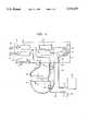
- FIG. 1is a schematic view of a dialysis machine adapted for priming.
- FIG. 2is a diagram showing calibration curves for pump segments of five different brands.
- FIG. 3is a diagram showing the same pump segments dependency on time.
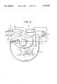
- FIG. 4is a schematic view similar to FIG. 1 and shows a first embodiment of the present invention.
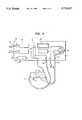
- FIG. 5is a schematic view similar to FIG. 4 and shows a second embodiment of the invention.
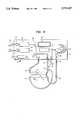
- FIG. 6is a schematic view similar to FIGS. 4 and shows a third embodiment of the invention.
- FIG. 7is a schematic view similar to FIG. 4 and shows a fourth embodiment of the invention.
- FIG. 8is a schematic view similar to FIG. 7 and shows a fifth embodiment of the invention.
- FIG. 9is a schematic view similar to FIG. 8 and shows a sixth embodiment of the invention.
- FIG. 1is a schematic diagram of a dialysis machine provided with a set of tubings and a dialyzer as set up before the start of a treatment for priming purpose.
- the dialysing machinecan be GAMBRO AK 100 intended for hemodialysis. Only those parts and details which are necessary for understanding the present invention are shown in FIG. 1.
- the dialysis machine 1comprises an inlet 31 for dialysis solution leading to an inlet pump 20. Then, the dialysis solution passes through a flow meter 19 for measuring the fluid flow rate. From the flow meter 19, the dialysis solution is emitted through a dialysate outlet 32.
- dialysate outlet 32From dialysate outlet 32, the dialysis solution is passed through a dialyzer 2, as explained in more details below, and back to a return inlet 33. From the return inlet 33, the dialysis solution passes through a second flow meter 18 and a pump 21 to a waste outlet 34. The spent dialysis solution is given off through waste outlet 34 to a waste.
- the dialyzer 2comprises two compartments, a first of which 3 is intended to comprise blood, and a second of which 4 is intended to comprise a dialysis solution.
- the second compartment 4has one inlet 7 and one outlet 8, which are connected to dialysate outlet 32 and return inlet 33 via hoses 5 and 6.
- the first compartment 3has one inlet 11 and one outlet 12. Inlet 11 and outlet 12 are connected to a patient via a set of tubings 14 ended by needles 35 and 37.
- the set of tubingscomprises a first hose 42 connecting needle 35 to the inlet of a peristaltic pump segment 36, the oulet of which being connected to the inlet 11 of dialyzer 2 via a second hose 43.
- the outlet 12 of dialyzer 2is connected to a drip chamber 38 and further to needle 37 via a third hose 44.
- the drip chamber 38is intended for ensuring that no air is delivered to the patient.
- the primingtakes place in the following way.
- the blood inlet needle 35is connected to a container 40 comprising sterile priming solution.
- the priming solutionis pumped via needle 35, blood tubing hose 42, pump segment 36, hose 43, inlet 11, dialyzer first compartment 3, outlet 12, drip chamber 38 and patient needle 37 to a waste 41.
- dialysis solutionis delivered to the second compartment 4 of the dialyzer 2 via solution inlet 31, pump 20, flow meter 19, outlet 32, hose 5, inlet 7, second compartment 4 of dialyzer, outlet 8, hose 6, inlet 33, flow meter 18, pump 21, waste outlet 34 to a waste.
- the dialyzer 2is tilted and moved until all air has escaped from the dialyzer. At the same time, any loose particles within the dialyzer 2 or its connections are removed by the fluid flow.
- needles 35 and 37are replaced by sterile needles and connected to the patient for taking out the blood of the patient into an extracorporeal circuit through the set of tubings, the peristaltic pump and the dialyzer.
- the blood flow rate through the extracorporeal circuitis, according to the prior art, calculated as a calibration factor multiplied by the revolution rate of a rotor 39 of the peristaltic pump 13.
- the calibration factoris determined on the basis of the internal diameter of the pump segment 36.
- the blood flow rate thus obtainedwill be in error if the inlet pressure to the peristaltic pump is low so that a substantial pressure difference is created over the peristaltic pump.
- it is known to take account of the pressure at the inlet of the pump segment and to adapt the calculated flow rate in dependence of the measured pressureconfer e.g. Danish patent application No. 74-4853 (Sandoz AG).
- Danish patent application No. 74-4853(Sandoz AG).
- such calibrationtakes place by using the internal equipment of a dialysis machine (or other medical machine comprising a flow meter).
- FIG. 2shows how the fluid flow, given on the vertical axle, through pump segments of five different brands is heavily dependent on the pressure, given on the horizontal axle, upstreams of the pump at constant pump speed.
- the flowdrops heavily with reducing pressure upstreams of the pump.
- Large negative pressure upstreams of the pumpcan occur if for example too narrow a needle is chosen or if the needle and/or blood tubes are blocked in some way between the patient and the pump.
- One reason for thiscan be that the negative pressure has a tendency to keep the pump segment pressed together even after the pump roll has passed. This effect is of course reduced if the pump segment has a large wall thickness and an elastic material is used.
- FIG. 3shows how the fluid flow through one and the same pump segment is dependent on time. This figure also shows how the pump efficiency changes with time for pump segments of five different brands.
- FIG. 4One way of calibrating a peristaltic pump segment using a fluid flow meter internal of the dialysis machine is shown in FIG. 4.
- the dialyzer 2is disconnected, compared with FIG. 1, and hoses 5 and 6 are connected to a safety by-pass circuit 9, including a pressure monitor 10.
- the dialysis machineis so adapted, that certain machine operations can only be performed when hoses 5 and 6 are connected to said by-pass circuit 9. Such operations are for example disinfection and cleaning of the machine and includes calibration of the peristaltic pump according to the first embodiment of the present invention.
- By-pass circuit 9includes a second inlet connection 15, which can be placed on the dialysis machine or be a T-connector at hose 6 or hose 5, as shown in FIG. 4.
- the connector 15is connected to the outlet of the peristaltic pump segment.
- the inlet of the peristaltic pump segmentis connected to the bag or container 40 comprising sterile priming solution as described in connection with FIG. 1.
- the pump segmentcomprises a connector 16 for connection to a pressure meter positioned internal of the dialysis machine.
- a pressure meterpositioned internal of the dialysis machine.
- the measured pressureis fed to a control and/or monitoring circuit 25, which also includes an inlet for rotor speed of the perstialtic pump.
- the dialysis machineis now operated so that a certain dialysate priming flow is passing inlet 31, pump 20, fluid flow meter 19, dialysate outlet 32, by-pass circuit 9, return inlet 33, fluid flow meter 18, pump 21 to waste outlet 34.
- Pumps 20 and 21are driven so as to provide a predetermined pressure corresponding to normal outlet pressure for the peristaltic pump during normal operation, for example a positiv pressure of about 200 mm Hg.
- the peristaltic pumpis operated at a certain constant revolution rate, whereby sterile solution is pumped from container 40, through pump segment 36 to connector 15 and then through fluid flow meter 18 to the waste outlet 34.
- the dialysis machinemeasures a fluid flow differential between fluid flow meters 19 and 18, and the differential is the addition from the peristaltic pump. At the same time, the pressure at the inlet of the peristaltic pump segment is measured.
- the measured pair of valuesare stored in the calculating circuit 25, which usually is a computer of the dialysis machine. Then, the inlet pressure is changed and new pairs of measured values of the fluid flow and the inlet pressure is stored. The procedure is repeated until sufficient number of pairs of measured values are obtained. The computer calculates a calibration curve, which then is used for determining the actual fluid flow during subsequent operation of the dialysis machine.
- the different inlet pressurescan be obtained in different ways.
- an adjustable throttle valve 23is used as shown in FIG. 4.
- the throttle valveis positioned at the medical machine and is controlled by said machine.
- the method according to the first embodimentcan be used in connection with initial filling up of the dialysis machine, when no dialyzer is connected.
- the calibrationis performed during priming of the dialyzer as shown and described in connection with FIG. 1.
- the outlet from the dialyzer 12is not fed to a waste 41 but connected to an inlet connector 15' of the dialysis machine adjacent return inlet 33.
- the connector 15'is shown in FIG. 5 as a T-connector of hose 6.
- the operation of the second embodimentis the same as for the first embodiment, but has the advantage that the dialyzer 2 is ready for use after the priming combined with calibration of the peristaltic pump.
- FIG. 6A third embodiment of the invention is shown in FIG. 6. This embodiment is similar to the embodiment according to FIG. 4, but the inlet to the peristaltic pump is connected to the T-connector 15. The outlet from the peristaltic pump is connected to a waste 41.
- the pumps 20 and 21 of the dialysis machineare driven so as to provide a certain negative pressure at the by-pass circuit 9 where the inlet to the peristaltic pump is connected.
- the peristaltic pumpis started and takes out a fluid flow from the dialysate flow.
- fluid flow meter 18shows a lower fluid flow rate than fluid flow meter 19 and the difference is the fluid flow to the peristaltic pump.
- the pressure between pumps 20 and 21is equal to the inlet pressure to the peristaltic pump.
- the computer of the dialysis machineis provided with pair of values of fluid flow rate and inlet pressures for obtaining a calibration curve.
- the inlet pressurecontinuously from a small positive pressure to a substantial negative pressure for obtaining the entire calibration curve.
- the calibration procedurecan be repeated for several revolution rates for the peristaltic pump rotor to have several sets of calibration curves.
- the negative pressurecan be obtained with and adjusted by means of an adjustable throttle valve 23 as mentioned above.
- FIG. 7shows a fourth embodiment of the invention where the calibration takes place during the priming of the dialyzer as in FIG. 5, but using the method of FIG. 6.
- dialysatefor calibrating the peristaltic pump segment if it cannot be assured that the dialysate is completely sterile, since the pump segment subsequently will be used for passing blood in an extracorporeal circuit, which must be sterile.
- dialysis machineshave an outlet for sterile filtered solution used for infusion during hemofiltration or hemodiafiltration, either post- or preinfusion.
- a dialysis machineis for example GAMBRO AK100 ULTRA.
- the dialysis solution used for priming and calibrationis first passed through a sterile filter.
- the dialysis solution through inlet 31is passed via pump 20 and fluid flow meter 19 to a sterile filter 45, which can be a hollow fibre filter or any other filter having a membran capable of passing solutes having a low molecular weight while preventing bacteria and endotoxins from passing the membrane.
- the filtered dialysis solutionis emitted through a sterile solution outlet 46 and usually added to an infusion inlet of the drip chamber.
- a preinfusionis performed by adding the sterile filtered dialysis solution adjacent inlet 11.
- the fifth embodiment of the present inventionincludes using the sterile filtered solution for priming the dialyzer 2 and calibrating the peristaltic pump segment.
- This fifth embodimentis shown in FIG. 8 and corresponds in all essentials to the fourth embodiment shown in FIG. 7, but the sterile filter 45 has been added. The operation is obvious from the above description.
- a sixth embodiment of the inventionis shown in FIG. 9 and comprises a dialyzer 2' used for hemofiltration, a so called hemofilter.
- a hemofilterlacks inlet 7 for dialysis solution and an ultrafiltrate is taken out from the blood through outlet 8'.
- the ultrafiltrateis compensated by addition of substitution solution from sterile filtered outlet 46 as mentioned above.
- Said hemofilteris primed by dialysis solution from sterile filtered outlet 46.
- the outlet 12 from the hemofilter 2'is fed to the inlet of the peristaltic pump.
- the difference between flow meters 19 and 18is the flow through the peristaltic pump.
- Pump 21controls the transmembrane pressure.
- the throttle valve 23can adjust the inlet pressure. The further operation is obvious from the above given description.
- a second peristaltic pumpis used for such purposes.
- Such second pumpcan be calibrated in the same way as described above.
- the peristaltic pump segmentis calibrated according to the invention while using a priming solution comprised in a container 40 or a dialysis solution from the dialysis machine. It is noted that blood usually is much more viscous than such solutions.
- the calibration curveis essentially independent of which fluid is pumped as soon as it is non-compressible, since the variation due to different inlet pressures mainly is dependent on the fact that the pump segment is not returned to its circular shape after each pump stroke.
- the calibration curveis mainly a property of the material and dimensions of the pump segment proper.
- the calibration curvewill change with time as shown and described with reference to FIG. 3. Such dependency is believed to be mainly dependent on fatigue in the material. It is also known that the elasticity of most plastic materials is very dependent on the temperature. Thus, it is prefered to perform the calibration at a temperature close to 37 degrees Celsius.
- Such a temperatureis easily achieved in the embodiments according to FIGS. 6, 7 and 8. In the embodiments according to FIGS. 4 and 5, such temperature can be obtained by heating the priming solution in container 40.
- the calibration pair valuesare compared to known calibration curves stored in the medical machine and the most correct calibration curve is selected. To select a correct curve, it is sufficient to have two pairs of values. One of the pair values can be given by the manufacturer for the actual type of pump segment, although measured values are preferred.
- the calibration curveis a second degree curve and it can be approximated by using three different pair values (of which one can be given by the manufacturer).
- Accountis also taken for the dependency of the fluid flow by time. Such adjustment is less dependent on different properties of the actual pump segment used but is more constant for the actual brand of pumps segment and is furthermore rather small, such as less than about 5%. Thus, values obtained from a data sheet can be used for such compensation.
- the actual fluid flow through the peristaltic pump during operation of the medical machinecan be obtained by measuring the inlet pressure and revolution rate of the peristaltic pump. From the calibration curves, an actual fluid flow can be determined. Such actual flow can be shown on the medical machine on a display thereof. Alternatively, said actual flow can be fed to a control device adapted to adjust the peristaltic pump to obtain a desired fluid flow. Further possibilities are obvious to a skilled person.
- the inventionis particurlarly intended to be used at dialysis.
- Some dialysis machinessuch as GAMBRO AK100, has an internal fluid flow meter directly measuring the fluid flow by using a magnetic field and measuring the electric properties of the fluid flow under influence of said magnetic field.
- Other dialysis machineshave other types of fluid flow meters using other physical properties for measuring the fluid flow.
- Still further dialysis machineshave constant deplacement pumps for measuring the fluid flow and simultaneous pumping the fluid, i.e. generating a pressure. All such types of "flow meters" are intended to be within the definition of the claims.
Landscapes
- Health & Medical Sciences (AREA)
- Engineering & Computer Science (AREA)
- Heart & Thoracic Surgery (AREA)
- Cardiology (AREA)
- General Health & Medical Sciences (AREA)
- Biomedical Technology (AREA)
- Hematology (AREA)
- Life Sciences & Earth Sciences (AREA)
- Animal Behavior & Ethology (AREA)
- Public Health (AREA)
- Veterinary Medicine (AREA)
- Anesthesiology (AREA)
- Mechanical Engineering (AREA)
- Vascular Medicine (AREA)
- Medical Informatics (AREA)
- Emergency Medicine (AREA)
- Pulmonology (AREA)
- General Engineering & Computer Science (AREA)
- Human Computer Interaction (AREA)
- Physics & Mathematics (AREA)
- Fluid Mechanics (AREA)
- External Artificial Organs (AREA)
- Reciprocating Pumps (AREA)
Abstract
Description
Claims (23)
Applications Claiming Priority (3)
| Application Number | Priority Date | Filing Date | Title |
|---|---|---|---|
| SE9303319 | 1993-10-11 | ||
| SE9303319ASE9303319D0 (en) | 1993-10-11 | 1993-10-11 | Methods of calculating and / or controlling flows for a certain period of time through a peristaltic pump and a monitor adapted to practice this method |
| PCT/SE1994/000952WO1995010310A1 (en) | 1993-10-11 | 1994-10-10 | Method for calibrating a pump segment used in a peristaltic pump and a medical machine adapted for carrying out the method |
Publications (1)
| Publication Number | Publication Date |
|---|---|
| US5733257Atrue US5733257A (en) | 1998-03-31 |
Family
ID=20391371
Family Applications (1)
| Application Number | Title | Priority Date | Filing Date |
|---|---|---|---|
| US08/602,749Expired - LifetimeUS5733257A (en) | 1993-10-11 | 1994-10-10 | Method for calibrating a pump segment used in a peristaltic pump and a medical machine adapted for carrying out the method |
Country Status (10)
| Country | Link |
|---|---|
| US (1) | US5733257A (en) |
| EP (1) | EP0723463B1 (en) |
| JP (1) | JP3615762B2 (en) |
| AT (1) | ATE200031T1 (en) |
| DE (1) | DE69426985T2 (en) |
| DK (1) | DK0723463T3 (en) |
| ES (1) | ES2155094T3 (en) |
| PT (1) | PT723463E (en) |
| SE (1) | SE9303319D0 (en) |
| WO (1) | WO1995010310A1 (en) |
Cited By (73)
| Publication number | Priority date | Publication date | Assignee | Title |
|---|---|---|---|---|
| US6139748A (en)* | 1997-09-22 | 2000-10-31 | Gambro Ab | Method and device for monitoring an infusion pump |
| GB2367594A (en)* | 2000-03-16 | 2002-04-10 | Aksys Ltd | Calibration of pumps such as blood pumps of dialysis machines |
| US6393338B1 (en) | 2000-03-17 | 2002-05-21 | Tadeusz Kemnitz | Apparatus and control method for accurate rotary peristaltic pump filling |
| US6495366B1 (en) | 1999-09-03 | 2002-12-17 | Therakos, Inc. | Uninterrupted flow pump apparatus and method |
| WO2003055542A1 (en) | 2001-12-27 | 2003-07-10 | Gambro Lundia Ab | Equipment for controlling blood flow in an extracorporeal blood circuit |
| US6793643B1 (en) | 2000-04-21 | 2004-09-21 | Therakos, Inc. | Low extracorporeal volume treatment system |
| WO2006097199A1 (en)* | 2005-03-15 | 2006-09-21 | Fresenius Medical Care Deutschland Gmbh | Method and device for determining the effective delivery rate or for adjusting the speed of a peristaltic pump |
| US20080275377A1 (en)* | 2005-05-18 | 2008-11-06 | Gambro Lundia Ab | Apparatus for Controlling Blood Flow in an Extracorporeal Circuit |
| US20090082793A1 (en)* | 2004-01-23 | 2009-03-26 | Allergan, Inc. | Releasably-securable one-piece adjustable gastric band |
| EP2085615A1 (en) | 2008-01-31 | 2009-08-05 | Massimo Dinelli | A peristaltic pump for supplying fluid products and a method for controlling said pump |
| US20100010291A1 (en)* | 2008-07-14 | 2010-01-14 | Allergan, Inc. | Implantable pump system with calibration |
| US20100087843A1 (en)* | 2008-10-06 | 2010-04-08 | Allergan, Inc. | Mechanical Gastric Band With Cushions |
| US20100185049A1 (en)* | 2008-10-22 | 2010-07-22 | Allergan, Inc. | Dome and screw valves for remotely adjustable gastric banding systems |
| US20100274274A1 (en)* | 2005-04-13 | 2010-10-28 | Allergan, Inc. | Artificial gastric valve |
| US20100280310A1 (en)* | 2009-05-01 | 2010-11-04 | Allergan, Inc. | Laparoscopic Gastric Band With Active Agents |
| US20100305397A1 (en)* | 2008-10-06 | 2010-12-02 | Allergan Medical Sarl | Hydraulic-mechanical gastric band |
| US20100324358A1 (en)* | 2006-01-04 | 2010-12-23 | Birk Janel A | Hydraulic gastric band with collapsible reservoir |
| US20100324359A1 (en)* | 2002-08-28 | 2010-12-23 | Janel Birk | Fatigue-resistant gastric banding device |
| US20110040141A1 (en)* | 2004-03-08 | 2011-02-17 | Allergan, Inc. | Closure system for tubular organs |
| US20110054248A1 (en)* | 2009-08-28 | 2011-03-03 | Allergan, Inc. | Gastric band with electric stimulation |
| US20110137112A1 (en)* | 2009-08-28 | 2011-06-09 | Allergan, Inc. | Gastric band with electric stimulation |
| US20110168291A1 (en)* | 2008-09-02 | 2011-07-14 | Josef Beden | Device for filling a filter, and method therefor |
| US20110184229A1 (en)* | 2009-05-01 | 2011-07-28 | Allergan, Inc. | Laparoscopic gastric band with active agents |
| US20110201875A1 (en)* | 2010-02-12 | 2011-08-18 | Allergan, Inc. | Remotely adjustable gastric banding system |
| US20110201874A1 (en)* | 2010-02-12 | 2011-08-18 | Allergan, Inc. | Remotely adjustable gastric banding system |
| US20110208229A1 (en)* | 2010-02-24 | 2011-08-25 | Allergan, Inc. | Source reservoir with potential energy for remotely adjustable gastric banding system |
| US20110207995A1 (en)* | 2010-02-25 | 2011-08-25 | Allergan, Inc. | Inductively powered remotely adjustable gastric banding system |
| US20110208220A1 (en)* | 2010-02-25 | 2011-08-25 | Allergan, Inc. | Pressure sensing gastric banding system |
| US8517915B2 (en) | 2010-06-10 | 2013-08-27 | Allergan, Inc. | Remotely adjustable gastric banding system |
| US8698373B2 (en) | 2010-08-18 | 2014-04-15 | Apollo Endosurgery, Inc. | Pare piezo power with energy recovery |
| US8722422B2 (en) | 1999-09-03 | 2014-05-13 | Therakos, Inc. | Uninterrupted flow pump apparatus and method |
| US8845513B2 (en) | 2002-08-13 | 2014-09-30 | Apollo Endosurgery, Inc. | Remotely adjustable gastric banding device |
| US8858185B2 (en) | 2010-06-23 | 2014-10-14 | Hospira, Inc. | Fluid flow rate compensation system using an integrated conductivity sensor to monitor tubing changes |
| US8876694B2 (en) | 2011-12-07 | 2014-11-04 | Apollo Endosurgery, Inc. | Tube connector with a guiding tip |
| US8905915B2 (en) | 2006-01-04 | 2014-12-09 | Apollo Endosurgery, Inc. | Self-regulating gastric band with pressure data processing |
| US8961394B2 (en) | 2011-12-20 | 2015-02-24 | Apollo Endosurgery, Inc. | Self-sealing fluid joint for use with a gastric band |
| US8961393B2 (en) | 2010-11-15 | 2015-02-24 | Apollo Endosurgery, Inc. | Gastric band devices and drive systems |
| US9028394B2 (en) | 2010-04-29 | 2015-05-12 | Apollo Endosurgery, Inc. | Self-adjusting mechanical gastric band |
| US9044298B2 (en) | 2010-04-29 | 2015-06-02 | Apollo Endosurgery, Inc. | Self-adjusting gastric band |
| US9050165B2 (en) | 2010-09-07 | 2015-06-09 | Apollo Endosurgery, Inc. | Remotely adjustable gastric banding system |
| CN104755761A (en)* | 2012-10-19 | 2015-07-01 | 日机装株式会社 | Pressure detection device for fluid flow path |
| US9192501B2 (en) | 2010-04-30 | 2015-11-24 | Apollo Endosurgery, Inc. | Remotely powered remotely adjustable gastric band system |
| US9211207B2 (en) | 2010-08-18 | 2015-12-15 | Apollo Endosurgery, Inc. | Power regulated implant |
| US9226840B2 (en) | 2010-06-03 | 2016-01-05 | Apollo Endosurgery, Inc. | Magnetically coupled implantable pump system and method |
| US9295573B2 (en) | 2010-04-29 | 2016-03-29 | Apollo Endosurgery, Inc. | Self-adjusting gastric band having various compliant components and/or a satiety booster |
| US9849226B2 (en) | 2014-12-19 | 2017-12-26 | Fenwal, Inc. | Systems and methods for real time calibration of pump stroke volumes during a blood separation procedure |
| CN107683151A (en)* | 2015-06-24 | 2018-02-09 | 日机装株式会社 | blood purification device |
| US10022498B2 (en) | 2011-12-16 | 2018-07-17 | Icu Medical, Inc. | System for monitoring and delivering medication to a patient and method of using the same to minimize the risks associated with automated therapy |
| US10166328B2 (en) | 2013-05-29 | 2019-01-01 | Icu Medical, Inc. | Infusion system which utilizes one or more sensors and additional information to make an air determination regarding the infusion system |
| US10342917B2 (en) | 2014-02-28 | 2019-07-09 | Icu Medical, Inc. | Infusion system and method which utilizes dual wavelength optical air-in-line detection |
| US10430761B2 (en) | 2011-08-19 | 2019-10-01 | Icu Medical, Inc. | Systems and methods for a graphical interface including a graphical representation of medical data |
| US10426882B2 (en) | 2003-12-16 | 2019-10-01 | Baxter International Inc. | Blood rinseback system and method |
| US10463788B2 (en) | 2012-07-31 | 2019-11-05 | Icu Medical, Inc. | Patient care system for critical medications |
| US10578474B2 (en) | 2012-03-30 | 2020-03-03 | Icu Medical, Inc. | Air detection system and method for detecting air in a pump of an infusion system |
| US10596316B2 (en) | 2013-05-29 | 2020-03-24 | Icu Medical, Inc. | Infusion system and method of use which prevents over-saturation of an analog-to-digital converter |
| US10635784B2 (en) | 2007-12-18 | 2020-04-28 | Icu Medical, Inc. | User interface improvements for medical devices |
| US10656894B2 (en) | 2017-12-27 | 2020-05-19 | Icu Medical, Inc. | Synchronized display of screen content on networked devices |
| US20200164116A1 (en)* | 2018-11-26 | 2020-05-28 | Alcon Inc. | Methods and systems for controlling aspiration flow rate |
| US10850024B2 (en) | 2015-03-02 | 2020-12-01 | Icu Medical, Inc. | Infusion system, device, and method having advanced infusion features |
| US10874793B2 (en) | 2013-05-24 | 2020-12-29 | Icu Medical, Inc. | Multi-sensor infusion system for detecting air or an occlusion in the infusion system |
| US11135360B1 (en) | 2020-12-07 | 2021-10-05 | Icu Medical, Inc. | Concurrent infusion with common line auto flush |
| US11246985B2 (en) | 2016-05-13 | 2022-02-15 | Icu Medical, Inc. | Infusion pump system and method with common line auto flush |
| US11278671B2 (en) | 2019-12-04 | 2022-03-22 | Icu Medical, Inc. | Infusion pump with safety sequence keypad |
| US11298446B2 (en) | 2014-12-19 | 2022-04-12 | Fenwal, Inc. | Systems and methods for calibrating pump stroke volumes during a blood separation procedure |
| US11324888B2 (en) | 2016-06-10 | 2022-05-10 | Icu Medical, Inc. | Acoustic flow sensor for continuous medication flow measurements and feedback control of infusion |
| US11344673B2 (en) | 2014-05-29 | 2022-05-31 | Icu Medical, Inc. | Infusion system and pump with configurable closed loop delivery rate catch-up |
| US11344668B2 (en) | 2014-12-19 | 2022-05-31 | Icu Medical, Inc. | Infusion system with concurrent TPN/insulin infusion |
| CN116549769A (en)* | 2022-01-27 | 2023-08-08 | 深圳市巨鼎医疗股份有限公司 | Flow regulating method of injection device, injection device and storage medium |
| US11883361B2 (en) | 2020-07-21 | 2024-01-30 | Icu Medical, Inc. | Fluid transfer devices and methods of use |
| US20240035465A1 (en)* | 2022-07-26 | 2024-02-01 | Brian S. Whitmore | Modular Metering Pump System |
| EP4329840A4 (en)* | 2021-04-28 | 2025-02-26 | The Children's Hospital Of Philadelphia | TRANSFER TRAY AND PREPARATION CART FOR NEWBORN CANNULATING AND RELATED PROCEDURES |
| US12350233B2 (en) | 2021-12-10 | 2025-07-08 | Icu Medical, Inc. | Medical fluid compounding systems with coordinated flow control |
| USD1091564S1 (en) | 2021-10-13 | 2025-09-02 | Icu Medical, Inc. | Display screen or portion thereof with graphical user interface for a medical device |
Families Citing this family (9)
| Publication number | Priority date | Publication date | Assignee | Title |
|---|---|---|---|---|
| ITMO20030165A1 (en)* | 2003-06-04 | 2004-12-05 | Gambro Lundia Ab | JOINT FOR FLUID TRANSPORT LINES FOR MEDICAL USE. |
| JP5728632B2 (en)* | 2010-08-06 | 2015-06-03 | 株式会社テクトロン | Method for calibrating occlusion pressure in medical liquid pump and medical liquid pump |
| JP5863871B2 (en) | 2014-04-15 | 2016-02-17 | 日機装株式会社 | Mounting member and ironing pump |
| EP3031485B1 (en) | 2014-12-10 | 2018-11-21 | B. Braun Avitum AG | Method and control apparatus for determining and adjusting a flow rate of a blood delivery pump |
| DE102017115429A1 (en) | 2017-07-10 | 2019-01-10 | Fresenius Medical Care Deutschland Gmbh | Methods and apparatus for calibrating a pump for blood treatment |
| JP6464238B1 (en) | 2017-09-07 | 2019-02-06 | 日機装株式会社 | Blood purification apparatus and method for discharging bubbles |
| JP6462077B1 (en) | 2017-09-07 | 2019-01-30 | 日機装株式会社 | Blood purification apparatus and method for discharging bubbles |
| EP3715632B9 (en) | 2019-03-26 | 2023-07-12 | Grifols, S.A. | Method for calibrating a peristaltic pump, method for dispensing a quantity of liquid by means of a peristaltic pump and device for producing sterile preparations that can execute said methods |
| DE102023127245A1 (en)* | 2023-10-06 | 2025-04-10 | E.G.O. Elektro-Gerätebau GmbH | Method for operating a hydraulic device with rotatable hydraulic means |
Citations (6)
| Publication number | Priority date | Publication date | Assignee | Title |
|---|---|---|---|---|
| US4797655A (en)* | 1986-03-24 | 1989-01-10 | Gambro Ab | Detector system for monitoring a fluid containing tube |
| EP0315312A1 (en)* | 1987-11-02 | 1989-05-10 | Imed Corporation | Device and method for detecting a partial restriction |
| WO1990006781A1 (en)* | 1988-12-13 | 1990-06-28 | Bio-Flo Limited | Fluid flow control apparatus |
| WO1991009229A1 (en)* | 1989-12-14 | 1991-06-27 | Baxter International Inc. | Accurate peristaltic pump |
| US5057278A (en)* | 1990-04-26 | 1991-10-15 | Minnesota Mining And Manufacturing Company | Sterile loop calibration system |
| US5372709A (en)* | 1988-12-13 | 1994-12-13 | Bio-Flo Limited | Fluid flow control apparatus |
- 1993
- 1993-10-11SESE9303319Apatent/SE9303319D0/enunknown
- 1994
- 1994-10-10WOPCT/SE1994/000952patent/WO1995010310A1/enactiveIP Right Grant
- 1994-10-10EPEP94929719Apatent/EP0723463B1/ennot_activeExpired - Lifetime
- 1994-10-10DEDE69426985Tpatent/DE69426985T2/ennot_activeExpired - Lifetime
- 1994-10-10PTPT94929719Tpatent/PT723463E/enunknown
- 1994-10-10JPJP51167895Apatent/JP3615762B2/ennot_activeExpired - Fee Related
- 1994-10-10ATAT94929719Tpatent/ATE200031T1/ennot_activeIP Right Cessation
- 1994-10-10ESES94929719Tpatent/ES2155094T3/ennot_activeExpired - Lifetime
- 1994-10-10USUS08/602,749patent/US5733257A/ennot_activeExpired - Lifetime
- 1994-10-10DKDK94929719Tpatent/DK0723463T3/enactive
Patent Citations (6)
| Publication number | Priority date | Publication date | Assignee | Title |
|---|---|---|---|---|
| US4797655A (en)* | 1986-03-24 | 1989-01-10 | Gambro Ab | Detector system for monitoring a fluid containing tube |
| EP0315312A1 (en)* | 1987-11-02 | 1989-05-10 | Imed Corporation | Device and method for detecting a partial restriction |
| WO1990006781A1 (en)* | 1988-12-13 | 1990-06-28 | Bio-Flo Limited | Fluid flow control apparatus |
| US5372709A (en)* | 1988-12-13 | 1994-12-13 | Bio-Flo Limited | Fluid flow control apparatus |
| WO1991009229A1 (en)* | 1989-12-14 | 1991-06-27 | Baxter International Inc. | Accurate peristaltic pump |
| US5057278A (en)* | 1990-04-26 | 1991-10-15 | Minnesota Mining And Manufacturing Company | Sterile loop calibration system |
Cited By (131)
| Publication number | Priority date | Publication date | Assignee | Title |
|---|---|---|---|---|
| US6139748A (en)* | 1997-09-22 | 2000-10-31 | Gambro Ab | Method and device for monitoring an infusion pump |
| US8722422B2 (en) | 1999-09-03 | 2014-05-13 | Therakos, Inc. | Uninterrupted flow pump apparatus and method |
| US6495366B1 (en) | 1999-09-03 | 2002-12-17 | Therakos, Inc. | Uninterrupted flow pump apparatus and method |
| US20030065284A1 (en)* | 1999-09-03 | 2003-04-03 | Briggs Dennis A. | Uninterrupted flow pump apparatus and method |
| US8153083B2 (en) | 1999-09-03 | 2012-04-10 | Therakos, Inc. | Uninterrupted flow pump apparatus and method |
| US20090209898A1 (en)* | 1999-09-03 | 2009-08-20 | Therakos, Inc. | Uninterrupted Flow Pump Apparatus and Method |
| US7534616B2 (en) | 1999-09-03 | 2009-05-19 | Therakos, Inc. | Uninterrupted flow pump apparatus and method |
| GB2367594B (en)* | 2000-03-16 | 2002-10-16 | Aksys Ltd | Calibration of pumps, such as blood pumps of dialysis machines |
| US6691047B1 (en) | 2000-03-16 | 2004-02-10 | Aksys, Ltd. | Calibration of pumps, such as blood pumps of dialysis machine |
| DE10112848B4 (en)* | 2000-03-16 | 2008-09-11 | HDH LLC. (n.d.Ges.d.Staates Delaware), Boston | Calibration of pumps such as blood pumps of dialysis machines |
| GB2367594A (en)* | 2000-03-16 | 2002-04-10 | Aksys Ltd | Calibration of pumps such as blood pumps of dialysis machines |
| US6393338B1 (en) | 2000-03-17 | 2002-05-21 | Tadeusz Kemnitz | Apparatus and control method for accurate rotary peristaltic pump filling |
| US6793643B1 (en) | 2000-04-21 | 2004-09-21 | Therakos, Inc. | Low extracorporeal volume treatment system |
| US7993297B2 (en) | 2001-12-27 | 2011-08-09 | Gambro Lundia Ab | Apparatus for controlling blood flow in an extracorporeal blood circuit |
| US7824354B2 (en) | 2001-12-27 | 2010-11-02 | Gambro Lundia Ab | Process for controlling blood flow in an extracorporeal blood circuit |
| WO2003055542A1 (en) | 2001-12-27 | 2003-07-10 | Gambro Lundia Ab | Equipment for controlling blood flow in an extracorporeal blood circuit |
| US20080119777A1 (en)* | 2001-12-27 | 2008-05-22 | Luca Vinci | Process for controlling blood flow in an extracorporeal blood circuit |
| US20050043665A1 (en)* | 2001-12-27 | 2005-02-24 | Luca Vinci | Equipment for controlling blood flow in an extracorporeal blood circuit |
| US7648477B2 (en) | 2001-12-27 | 2010-01-19 | Gambro Lundia Ab | Process for controlling blood flow in an extracorporeal blood circuit |
| KR100939514B1 (en)* | 2001-12-27 | 2010-02-03 | 감브로 룬디아 아베 | Equipment for controlling blood flow in an extracorporeal blood circuit |
| US20100324465A1 (en)* | 2001-12-27 | 2010-12-23 | Gambro Lundia Ab | Apparatus for controlling blood flow in an extracorporeal blood circuit |
| US8845513B2 (en) | 2002-08-13 | 2014-09-30 | Apollo Endosurgery, Inc. | Remotely adjustable gastric banding device |
| US8382780B2 (en) | 2002-08-28 | 2013-02-26 | Allergan, Inc. | Fatigue-resistant gastric banding device |
| US20100324359A1 (en)* | 2002-08-28 | 2010-12-23 | Janel Birk | Fatigue-resistant gastric banding device |
| US10426882B2 (en) | 2003-12-16 | 2019-10-01 | Baxter International Inc. | Blood rinseback system and method |
| US11672897B2 (en) | 2003-12-16 | 2023-06-13 | Baxter International Inc. | Blood rinseback system and method |
| US8900117B2 (en) | 2004-01-23 | 2014-12-02 | Apollo Endosurgery, Inc. | Releasably-securable one-piece adjustable gastric band |
| US20090082793A1 (en)* | 2004-01-23 | 2009-03-26 | Allergan, Inc. | Releasably-securable one-piece adjustable gastric band |
| US8377081B2 (en) | 2004-03-08 | 2013-02-19 | Allergan, Inc. | Closure system for tubular organs |
| US20110040141A1 (en)* | 2004-03-08 | 2011-02-17 | Allergan, Inc. | Closure system for tubular organs |
| US20090234289A1 (en)* | 2005-03-15 | 2009-09-17 | Alfred Gagel | Method and Device for Determining the Effective Delivery Rate or Adjusting the Speed of a Peristaltic Pump |
| CN101142407B (en)* | 2005-03-15 | 2010-10-13 | 弗雷泽纽斯医疗保健德国有限公司 | Method and device for adjusting the speed of a peristaltic pump |
| US8140274B2 (en) | 2005-03-15 | 2012-03-20 | Fresenius Medical Care Deutschland Gmbh | Method and device for determining the effective delivery rate or adjusting the speed of a peristaltic pump |
| DE102005023430A1 (en)* | 2005-03-15 | 2006-09-21 | Fresenius Medical Care Deutschland Gmbh | Method and device for determining the effective delivery rate or setting the speed of a peristaltic pump |
| WO2006097199A1 (en)* | 2005-03-15 | 2006-09-21 | Fresenius Medical Care Deutschland Gmbh | Method and device for determining the effective delivery rate or for adjusting the speed of a peristaltic pump |
| US8623042B2 (en) | 2005-04-13 | 2014-01-07 | Mitchell Roslin | Artificial gastric valve |
| US20100274274A1 (en)* | 2005-04-13 | 2010-10-28 | Allergan, Inc. | Artificial gastric valve |
| US7794419B2 (en) | 2005-05-18 | 2010-09-14 | Gambro Lundia Ab | Apparatus for controlling blood flow in an extracorporeal circuit |
| US20080275377A1 (en)* | 2005-05-18 | 2008-11-06 | Gambro Lundia Ab | Apparatus for Controlling Blood Flow in an Extracorporeal Circuit |
| US8308630B2 (en) | 2006-01-04 | 2012-11-13 | Allergan, Inc. | Hydraulic gastric band with collapsible reservoir |
| US8323180B2 (en) | 2006-01-04 | 2012-12-04 | Allergan, Inc. | Hydraulic gastric band with collapsible reservoir |
| US8905915B2 (en) | 2006-01-04 | 2014-12-09 | Apollo Endosurgery, Inc. | Self-regulating gastric band with pressure data processing |
| US20100324358A1 (en)* | 2006-01-04 | 2010-12-23 | Birk Janel A | Hydraulic gastric band with collapsible reservoir |
| US10635784B2 (en) | 2007-12-18 | 2020-04-28 | Icu Medical, Inc. | User interface improvements for medical devices |
| EP2085615A1 (en) | 2008-01-31 | 2009-08-05 | Massimo Dinelli | A peristaltic pump for supplying fluid products and a method for controlling said pump |
| US20100010291A1 (en)* | 2008-07-14 | 2010-01-14 | Allergan, Inc. | Implantable pump system with calibration |
| US8376929B2 (en)* | 2008-07-14 | 2013-02-19 | Allergan, Inc. | Implantable pump system with calibration |
| US8875748B2 (en) | 2008-09-02 | 2014-11-04 | Fresenius Medical Care Deutschland Gmbh | Device for filling a filter, and method therefor |
| US20110168291A1 (en)* | 2008-09-02 | 2011-07-14 | Josef Beden | Device for filling a filter, and method therefor |
| US8317677B2 (en) | 2008-10-06 | 2012-11-27 | Allergan, Inc. | Mechanical gastric band with cushions |
| US20100305397A1 (en)* | 2008-10-06 | 2010-12-02 | Allergan Medical Sarl | Hydraulic-mechanical gastric band |
| US20100087843A1 (en)* | 2008-10-06 | 2010-04-08 | Allergan, Inc. | Mechanical Gastric Band With Cushions |
| US8900118B2 (en) | 2008-10-22 | 2014-12-02 | Apollo Endosurgery, Inc. | Dome and screw valves for remotely adjustable gastric banding systems |
| US20100185049A1 (en)* | 2008-10-22 | 2010-07-22 | Allergan, Inc. | Dome and screw valves for remotely adjustable gastric banding systems |
| US20110184229A1 (en)* | 2009-05-01 | 2011-07-28 | Allergan, Inc. | Laparoscopic gastric band with active agents |
| US20100280310A1 (en)* | 2009-05-01 | 2010-11-04 | Allergan, Inc. | Laparoscopic Gastric Band With Active Agents |
| US20110054248A1 (en)* | 2009-08-28 | 2011-03-03 | Allergan, Inc. | Gastric band with electric stimulation |
| US20110137112A1 (en)* | 2009-08-28 | 2011-06-09 | Allergan, Inc. | Gastric band with electric stimulation |
| US20110201874A1 (en)* | 2010-02-12 | 2011-08-18 | Allergan, Inc. | Remotely adjustable gastric banding system |
| US8678993B2 (en) | 2010-02-12 | 2014-03-25 | Apollo Endosurgery, Inc. | Remotely adjustable gastric banding system |
| US20110201875A1 (en)* | 2010-02-12 | 2011-08-18 | Allergan, Inc. | Remotely adjustable gastric banding system |
| US20110208229A1 (en)* | 2010-02-24 | 2011-08-25 | Allergan, Inc. | Source reservoir with potential energy for remotely adjustable gastric banding system |
| US8758221B2 (en)* | 2010-02-24 | 2014-06-24 | Apollo Endosurgery, Inc. | Source reservoir with potential energy for remotely adjustable gastric banding system |
| US20110207995A1 (en)* | 2010-02-25 | 2011-08-25 | Allergan, Inc. | Inductively powered remotely adjustable gastric banding system |
| US8840541B2 (en) | 2010-02-25 | 2014-09-23 | Apollo Endosurgery, Inc. | Pressure sensing gastric banding system |
| US20110208220A1 (en)* | 2010-02-25 | 2011-08-25 | Allergan, Inc. | Pressure sensing gastric banding system |
| US8764624B2 (en) | 2010-02-25 | 2014-07-01 | Apollo Endosurgery, Inc. | Inductively powered remotely adjustable gastric banding system |
| US9044298B2 (en) | 2010-04-29 | 2015-06-02 | Apollo Endosurgery, Inc. | Self-adjusting gastric band |
| US9295573B2 (en) | 2010-04-29 | 2016-03-29 | Apollo Endosurgery, Inc. | Self-adjusting gastric band having various compliant components and/or a satiety booster |
| US9028394B2 (en) | 2010-04-29 | 2015-05-12 | Apollo Endosurgery, Inc. | Self-adjusting mechanical gastric band |
| US9192501B2 (en) | 2010-04-30 | 2015-11-24 | Apollo Endosurgery, Inc. | Remotely powered remotely adjustable gastric band system |
| US9226840B2 (en) | 2010-06-03 | 2016-01-05 | Apollo Endosurgery, Inc. | Magnetically coupled implantable pump system and method |
| US8517915B2 (en) | 2010-06-10 | 2013-08-27 | Allergan, Inc. | Remotely adjustable gastric banding system |
| US8858185B2 (en) | 2010-06-23 | 2014-10-14 | Hospira, Inc. | Fluid flow rate compensation system using an integrated conductivity sensor to monitor tubing changes |
| US8698373B2 (en) | 2010-08-18 | 2014-04-15 | Apollo Endosurgery, Inc. | Pare piezo power with energy recovery |
| US9211207B2 (en) | 2010-08-18 | 2015-12-15 | Apollo Endosurgery, Inc. | Power regulated implant |
| US9050165B2 (en) | 2010-09-07 | 2015-06-09 | Apollo Endosurgery, Inc. | Remotely adjustable gastric banding system |
| US8961393B2 (en) | 2010-11-15 | 2015-02-24 | Apollo Endosurgery, Inc. | Gastric band devices and drive systems |
| US11972395B2 (en) | 2011-08-19 | 2024-04-30 | Icu Medical, Inc. | Systems and methods for a graphical interface including a graphical representation of medical data |
| US12346879B2 (en) | 2011-08-19 | 2025-07-01 | Icu Medical, Inc. | Systems and methods for a graphical interface including a graphical representation of medical data |
| US11004035B2 (en) | 2011-08-19 | 2021-05-11 | Icu Medical, Inc. | Systems and methods for a graphical interface including a graphical representation of medical data |
| US11599854B2 (en) | 2011-08-19 | 2023-03-07 | Icu Medical, Inc. | Systems and methods for a graphical interface including a graphical representation of medical data |
| US10430761B2 (en) | 2011-08-19 | 2019-10-01 | Icu Medical, Inc. | Systems and methods for a graphical interface including a graphical representation of medical data |
| US8876694B2 (en) | 2011-12-07 | 2014-11-04 | Apollo Endosurgery, Inc. | Tube connector with a guiding tip |
| US10022498B2 (en) | 2011-12-16 | 2018-07-17 | Icu Medical, Inc. | System for monitoring and delivering medication to a patient and method of using the same to minimize the risks associated with automated therapy |
| US11376361B2 (en) | 2011-12-16 | 2022-07-05 | Icu Medical, Inc. | System for monitoring and delivering medication to a patient and method of using the same to minimize the risks associated with automated therapy |
| US8961394B2 (en) | 2011-12-20 | 2015-02-24 | Apollo Endosurgery, Inc. | Self-sealing fluid joint for use with a gastric band |
| US10578474B2 (en) | 2012-03-30 | 2020-03-03 | Icu Medical, Inc. | Air detection system and method for detecting air in a pump of an infusion system |
| US11933650B2 (en) | 2012-03-30 | 2024-03-19 | Icu Medical, Inc. | Air detection system and method for detecting air in a pump of an infusion system |
| US11623042B2 (en) | 2012-07-31 | 2023-04-11 | Icu Medical, Inc. | Patient care system for critical medications |
| US10463788B2 (en) | 2012-07-31 | 2019-11-05 | Icu Medical, Inc. | Patient care system for critical medications |
| US12280239B2 (en) | 2012-07-31 | 2025-04-22 | Icu Medical, Inc. | Patient care system for critical medications |
| CN104755761B (en)* | 2012-10-19 | 2017-03-08 | 日机装株式会社 | The pressure-detecting device of liquid flow path |
| CN104755761A (en)* | 2012-10-19 | 2015-07-01 | 日机装株式会社 | Pressure detection device for fluid flow path |
| US12048831B2 (en) | 2013-05-24 | 2024-07-30 | Icu Medical, Inc. | Multi-sensor infusion system for detecting air or an occlusion in the infusion system |
| US10874793B2 (en) | 2013-05-24 | 2020-12-29 | Icu Medical, Inc. | Multi-sensor infusion system for detecting air or an occlusion in the infusion system |
| US10166328B2 (en) | 2013-05-29 | 2019-01-01 | Icu Medical, Inc. | Infusion system which utilizes one or more sensors and additional information to make an air determination regarding the infusion system |
| US11433177B2 (en) | 2013-05-29 | 2022-09-06 | Icu Medical, Inc. | Infusion system which utilizes one or more sensors and additional information to make an air determination regarding the infusion system |
| US12059551B2 (en) | 2013-05-29 | 2024-08-13 | Icu Medical, Inc. | Infusion system and method of use which prevents over-saturation of an analog-to-digital converter |
| US10596316B2 (en) | 2013-05-29 | 2020-03-24 | Icu Medical, Inc. | Infusion system and method of use which prevents over-saturation of an analog-to-digital converter |
| US11596737B2 (en) | 2013-05-29 | 2023-03-07 | Icu Medical, Inc. | Infusion system and method of use which prevents over-saturation of an analog-to-digital converter |
| US12083310B2 (en) | 2014-02-28 | 2024-09-10 | Icu Medical, Inc. | Infusion system and method which utilizes dual wavelength optical air-in-line detection |
| US10342917B2 (en) | 2014-02-28 | 2019-07-09 | Icu Medical, Inc. | Infusion system and method which utilizes dual wavelength optical air-in-line detection |
| US11344673B2 (en) | 2014-05-29 | 2022-05-31 | Icu Medical, Inc. | Infusion system and pump with configurable closed loop delivery rate catch-up |
| US11344668B2 (en) | 2014-12-19 | 2022-05-31 | Icu Medical, Inc. | Infusion system with concurrent TPN/insulin infusion |
| US11298446B2 (en) | 2014-12-19 | 2022-04-12 | Fenwal, Inc. | Systems and methods for calibrating pump stroke volumes during a blood separation procedure |
| US9849226B2 (en) | 2014-12-19 | 2017-12-26 | Fenwal, Inc. | Systems and methods for real time calibration of pump stroke volumes during a blood separation procedure |
| US10850024B2 (en) | 2015-03-02 | 2020-12-01 | Icu Medical, Inc. | Infusion system, device, and method having advanced infusion features |
| US12115337B2 (en) | 2015-03-02 | 2024-10-15 | Icu Medical, Inc. | Infusion system, device, and method having advanced infusion features |
| CN107683151A (en)* | 2015-06-24 | 2018-02-09 | 日机装株式会社 | blood purification device |
| US12201811B2 (en) | 2016-05-13 | 2025-01-21 | Icu Medical, Inc. | Infusion pump system and method with common line auto flush |
| US11246985B2 (en) | 2016-05-13 | 2022-02-15 | Icu Medical, Inc. | Infusion pump system and method with common line auto flush |
| US11324888B2 (en) | 2016-06-10 | 2022-05-10 | Icu Medical, Inc. | Acoustic flow sensor for continuous medication flow measurements and feedback control of infusion |
| US12076531B2 (en) | 2016-06-10 | 2024-09-03 | Icu Medical, Inc. | Acoustic flow sensor for continuous medication flow measurements and feedback control of infusion |
| US10656894B2 (en) | 2017-12-27 | 2020-05-19 | Icu Medical, Inc. | Synchronized display of screen content on networked devices |
| US11029911B2 (en) | 2017-12-27 | 2021-06-08 | Icu Medical, Inc. | Synchronized display of screen content on networked devices |
| US12333201B2 (en) | 2017-12-27 | 2025-06-17 | Icu Medical, Inc. | Synchronized display of screen content on networked devices |
| US11868161B2 (en) | 2017-12-27 | 2024-01-09 | Icu Medical, Inc. | Synchronized display of screen content on networked devices |
| US20200164116A1 (en)* | 2018-11-26 | 2020-05-28 | Alcon Inc. | Methods and systems for controlling aspiration flow rate |
| US12268843B2 (en) | 2019-12-04 | 2025-04-08 | Icu Medical, Inc. | Infusion pump with safety sequence keypad |
| US11278671B2 (en) | 2019-12-04 | 2022-03-22 | Icu Medical, Inc. | Infusion pump with safety sequence keypad |
| US12310921B2 (en) | 2020-07-21 | 2025-05-27 | Icu Medical, Inc. | Fluid transfer devices and methods of use |
| US11883361B2 (en) | 2020-07-21 | 2024-01-30 | Icu Medical, Inc. | Fluid transfer devices and methods of use |
| US11135360B1 (en) | 2020-12-07 | 2021-10-05 | Icu Medical, Inc. | Concurrent infusion with common line auto flush |
| US12390586B2 (en) | 2020-12-07 | 2025-08-19 | Icu Medical, Inc. | Concurrent infusion with common line auto flush |
| EP4329840A4 (en)* | 2021-04-28 | 2025-02-26 | The Children's Hospital Of Philadelphia | TRANSFER TRAY AND PREPARATION CART FOR NEWBORN CANNULATING AND RELATED PROCEDURES |
| USD1091564S1 (en) | 2021-10-13 | 2025-09-02 | Icu Medical, Inc. | Display screen or portion thereof with graphical user interface for a medical device |
| US12350233B2 (en) | 2021-12-10 | 2025-07-08 | Icu Medical, Inc. | Medical fluid compounding systems with coordinated flow control |
| CN116549769A (en)* | 2022-01-27 | 2023-08-08 | 深圳市巨鼎医疗股份有限公司 | Flow regulating method of injection device, injection device and storage medium |
| US11988203B2 (en)* | 2022-07-26 | 2024-05-21 | Brian S. Whitmore, Sr. | Modular metering pump system |
| US20240035465A1 (en)* | 2022-07-26 | 2024-02-01 | Brian S. Whitmore | Modular Metering Pump System |
Also Published As
| Publication number | Publication date |
|---|---|
| EP0723463A1 (en) | 1996-07-31 |
| DK0723463T3 (en) | 2001-04-30 |
| DE69426985T2 (en) | 2001-07-19 |
| JP3615762B2 (en) | 2005-02-02 |
| PT723463E (en) | 2001-09-28 |
| DE69426985D1 (en) | 2001-05-03 |
| SE9303319D0 (en) | 1993-10-11 |
| ES2155094T3 (en) | 2001-05-01 |
| WO1995010310A1 (en) | 1995-04-20 |
| JPH09503415A (en) | 1997-04-08 |
| EP0723463B1 (en) | 2001-03-28 |
| ATE200031T1 (en) | 2001-04-15 |
Similar Documents
| Publication | Publication Date | Title |
|---|---|---|
| US5733257A (en) | Method for calibrating a pump segment used in a peristaltic pump and a medical machine adapted for carrying out the method | |
| EP1276522B1 (en) | Method and device for monitoring the flow speed of an infusion solution | |
| US8388567B2 (en) | Apparatus for extracorporeal blood treatment | |
| US7494590B2 (en) | Method of controlling a dialysis apparatus | |
| EP0607301B1 (en) | Hemofiltration system | |
| EP1450879B1 (en) | Method of priming a dialysis machine | |
| KR100857291B1 (en) | Method and apparatus for hemodialysis delivery module | |
| CN105688299B (en) | Method and control device for determining and adjusting the flow rate of a blood-conveying pump | |
| US8676512B2 (en) | Method and device for determining the transmembrane pressure in an extracorporeal blood treatment | |
| US8500671B2 (en) | Device for extracorporeal blood treatment in single-needle operation mode | |
| SE510286C2 (en) | Method and Device for Monitoring Infusion Pump in a Hemo or Hemodia Filtration Machine | |
| JPH0455075B2 (en) | ||
| US9119922B2 (en) | Apparatus and method for identifying a tubing system for an extracorporeal blood treatment device | |
| US10220130B2 (en) | Device and method for balancing between an inflow into and an outflow out of a medical treatment device | |
| WO2024150754A1 (en) | Blood purification device | |
| CN117752880A (en) | Leak detection method and system, in particular for blood treatment devices |
Legal Events
| Date | Code | Title | Description |
|---|---|---|---|
| AS | Assignment | Owner name:GAMBRO AB, SWEDEN Free format text:ASSIGNMENT OF ASSIGNORS INTEREST;ASSIGNOR:STERNBY, JAN;REEL/FRAME:007884/0183 Effective date:19960124 | |
| STCF | Information on status: patent grant | Free format text:PATENTED CASE | |
| CC | Certificate of correction | ||
| FPAY | Fee payment | Year of fee payment:4 | |
| FEPP | Fee payment procedure | Free format text:PAYOR NUMBER ASSIGNED (ORIGINAL EVENT CODE: ASPN); ENTITY STATUS OF PATENT OWNER: LARGE ENTITY | |
| AS | Assignment | Owner name:GAMBRO LUNDIA AB, SWEDEN Free format text:CHANGE OF NAME;ASSIGNOR:GAMBRO AB;REEL/FRAME:014852/0515 Effective date:20031017 | |
| AS | Assignment | Owner name:GAMBRO LUNDIA AB, SWEDEN Free format text:CHANGE OF NAME;ASSIGNOR:GAMBRO AB;REEL/FRAME:015766/0199 Effective date:20031017 | |
| FPAY | Fee payment | Year of fee payment:8 | |
| AS | Assignment | Owner name:CITICORP TRUSTEE COMPANY LIMITED, AS SECURITY AGEN Free format text:SECURITY AGREEMENT;ASSIGNOR:GAMBRO LUNDIA AB;REEL/FRAME:018552/0691 Effective date:20061117 | |
| FPAY | Fee payment | Year of fee payment:12 | |
| AS | Assignment | Owner name:GAMBRO LUNDIA AB, COLORADO Free format text:RELEASE OF SECURITY INTEREST IN PATENTS;ASSIGNOR:CITICORP TRUSTEE COMPANY LIMITED, AS SECURITY AGENT;REEL/FRAME:027456/0050 Effective date:20111207 |