US5731876A - Method and apparatus for on-line determination of the thickness of a multilayer film using a partially reflecting roller and low coherence reflectometry - Google Patents
Method and apparatus for on-line determination of the thickness of a multilayer film using a partially reflecting roller and low coherence reflectometryDownload PDFInfo
- Publication number
- US5731876A US5731876AUS08/718,077US71807796AUS5731876AUS 5731876 AUS5731876 AUS 5731876AUS 71807796 AUS71807796 AUS 71807796AUS 5731876 AUS5731876 AUS 5731876A
- Authority
- US
- United States
- Prior art keywords
- film
- partially reflecting
- light
- receiver
- reflecting surface
- Prior art date
- Legal status (The legal status is an assumption and is not a legal conclusion. Google has not performed a legal analysis and makes no representation as to the accuracy of the status listed.)
- Expired - Fee Related
Links
- 238000000034methodMethods0.000titleclaimsabstractdescription31
- 238000002310reflectometryMethods0.000titledescription9
- 239000000523sampleSubstances0.000claimsabstractdescription16
- 230000003287optical effectEffects0.000claimsdescription17
- 238000001228spectrumMethods0.000claimsdescription9
- 239000011248coating agentSubstances0.000claimsdescription7
- 238000000576coating methodMethods0.000claimsdescription7
- 239000010408filmSubstances0.000description73
- 239000000835fiberSubstances0.000description13
- 238000005259measurementMethods0.000description9
- 238000004519manufacturing processMethods0.000description4
- 239000002245particleSubstances0.000description3
- 239000000203mixtureSubstances0.000description2
- 238000012544monitoring processMethods0.000description2
- 238000001579optical reflectometryMethods0.000description2
- 238000012937correctionMethods0.000description1
- 230000002950deficientEffects0.000description1
- 239000000839emulsionSubstances0.000description1
- 230000007257malfunctionEffects0.000description1
- 239000000463materialSubstances0.000description1
- 238000012986modificationMethods0.000description1
- 230000004048modificationEffects0.000description1
- 238000004886process controlMethods0.000description1
- 230000005855radiationEffects0.000description1
- 230000002285radioactive effectEffects0.000description1
- 239000012857radioactive materialSubstances0.000description1
- 238000006748scratchingMethods0.000description1
- 230000002393scratching effectEffects0.000description1
- 239000000126substanceSubstances0.000description1
- 238000012360testing methodMethods0.000description1
- 239000010409thin filmSubstances0.000description1
- 239000002699waste materialSubstances0.000description1
Images


Classifications
- G—PHYSICS
- G01—MEASURING; TESTING
- G01B—MEASURING LENGTH, THICKNESS OR SIMILAR LINEAR DIMENSIONS; MEASURING ANGLES; MEASURING AREAS; MEASURING IRREGULARITIES OF SURFACES OR CONTOURS
- G01B11/00—Measuring arrangements characterised by the use of optical techniques
- G01B11/02—Measuring arrangements characterised by the use of optical techniques for measuring length, width or thickness
- G01B11/06—Measuring arrangements characterised by the use of optical techniques for measuring length, width or thickness for measuring thickness ; e.g. of sheet material
- G01B11/0616—Measuring arrangements characterised by the use of optical techniques for measuring length, width or thickness for measuring thickness ; e.g. of sheet material of coating
- G01B11/0675—Measuring arrangements characterised by the use of optical techniques for measuring length, width or thickness for measuring thickness ; e.g. of sheet material of coating using interferometry
Definitions
- the present inventionrelates to optical reflectometry, and more particularly, to an apparatus for measuring the thickness of a film, web or sheet.
- film thicknessIn many industrial processes, control of film thickness is of critical importance. For example, the manufacture of photographic film requires the generation of a uniform layer of emulsion on a backing. From the point of view of process control, it is advantageous to be able to measure the film thickness during the film generation process rather than measuring the film in a laboratory after the film has been manufactured. If samples are measured off-line, correction of any machinery malfunction cannot be performed until after a considerable volume of defective material has been processed. This leads to waste.
- the term "film”includes sheets and webs.
- Prior art methods for measuring film thicknessmay be divided into contact and non-contact methods.
- a contact methoda micrometer that comes in physical contact with both sides of the film is employed.
- These methodshave the disadvantage of physically deforming the film during the measurement leading to inaccurate measurements and possible damage to the film from pitting or scratching.
- the methodsare difficult to apply for the on-line measurement of fast moving film webs.
- this methodcannot measure the relative thicknesses of the various layers in a multi-layer film.
- Non-contact methods based on the attenuation of a beam of subatomic particles or radiation such as beta particles or gamma raysare also known to the prior art.
- the attenuation of a beam of electrons by the filmis used to determine the film thickness in one prior art method of this type.
- This methodologyhas four disadvantages. First, the system must be calibrated for each type of film, since the attenuation depends on the chemical composition and density of the film. Second, the system typically relies on a radioactive source to generate the particle beam. It is generally desirable to limit the use of radioactive material for cost, safety, and psychological reasons. Third, access is normally required to both sides of the film so that the source can be placed on one side and the detector on the other. Finally, this method cannot determine the individual thicknesses in a multi-layer film.
- an optical autocorrelatoris defined to be an interferometer having a variable differential time delay.
- An optical autocorrelatoris described, for example, in chapter 5 of Statistical Optics, by Joseph W. Goodman (John Wiley & Sons, 1985, pp. 157-170). Those skilled in the art are aware of the principles of operation of an optical autocorrelator, but certain principles will be clarified here because of their relevance to this patent.
- the detected light intensityis measured as a function of a parameter.
- the detected light intensity expressed as a function of the differential time delayis called the coherence function of the input light.
- a receiver which determines the time delay between light reflected from different surfaces of a filmperforms the same function as a receiver which determines the path difference between light reflected from different surfaces of a film. Determining the spacing between peaks in the coherence function of the reflected light is yet another way to describe the same function.
- the term differential time delayshall include differential path lengths.
- a Michelson interferometeris an example of such an autocorrelator.
- An example of an apparatus for measuring film thickness which utilizes a Michelson interferometeris taught in U.S. Pat. No. 3,319,515 to Flournoy.
- the filmis illuminated with a collimated light beam at an angle with respect to the surface of the film.
- the front and back surfaces of the filmgenerate reflected light signals.
- the distance between the two reflecting surfacesis then determined by examining the peaks in the autocorrelation spectrum generated in a Michelson interferometer that receives the reflected light as its input.
- this methodcan determine only the product of the group index and the film thickness.
- the group indexis defined to be the ratio of the propagation velocity of a light pulse in a vacuum relative to the velocity of propagation of the pulse in the medium.
- the output of the autocorrelating interferometerconsists of a number of peaks whose locations depend on the difference in optical path length for each possible pair of reflecting boundaries. As the number of boundaries increases, the number of peaks increases rapidly. For example, a three layer film will generate an output having 13 peaks corresponding to the various "single pass" reflections in the system described above. There will be additional peaks corresponding to light that is reflected more than once in the film.
- the present inventioncomprises an apparatus and method for measuring the thickness of a film having top and bottom surfaces.
- the apparatusincludes low coherence light source that generates a probe light signal.
- the filmis positioned against a roller having a partially reflecting surface that is positioned at a fixed distance from the film.
- the probe light signalis applied to the film and is then reflected back through the film by the partially reflecting surface.
- the light leaving the filmis collected to form the input to a receiver that determines the time delay between light reflected from the top and bottom surfaces of the film.
- the receiver outputmay also be used to determine the thickness of the various layers in a multi-layer film.
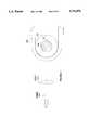
- FIG. 1is a schematic drawing of a thickness monitoring apparatus that utilizes a partially reflecting reference reflector.
- FIG. 2illustrates an arrangement in which a partially reflecting reflector is used to simplify the interpretation of the output of the autocorrelator when a two layer film is measured.
- FIG. 3illustrates the output generated by an autocorrelator receiver when the arrangement shown in FIG. 2 is utilized.
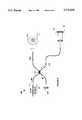
- FIG. 4is a schematic drawing of the preferred embodiment of a reference reflector according to the present invention.
- FIG. 5is a schematic drawing of an embodiment of the present invention that utilizes two probes to provide measurements of the thickness of the film at two different locations utilizing the same receiver.
- FIG. 6is a schematic drawing of an embodiment of the present invention that utilizes a reflectrometer for the receiver.
- FIG. 1is a schematic drawing of a thickness monitoring apparatus that utilizes a partially reflecting reference reflector 25.
- Apparatus 10utilizes a low coherence light source 12 to generate a light signal that is applied to the film 15 to be measured.
- a reference reflector 25is located behind film 15.
- reference reflector 25is a partially reflecting surface.
- Light reflected back into fiber 14 that passes through film 15is collected by lens 27 and routed to a receiver 18 with the aid of a coupler 16 and fiber 17.
- Receiver 18is preferably an autocorrelator; however, other forms of receivers may be utilized.
- the coherence length of light source 12must be small compared to the thickness of the film being measured.
- Such light sourcesare common in the optical reflectometry arts, and hence, will not be discussed in detail here. For the purposes of the present discussion, it is sufficient to note that an edge emitting light emitting diode may be utilized for light source 12.
- An exemplary autocorrelator 18 constructed from a Michelson interferometeris shown at 18.
- the light incident on Michelson interferometeris split into two beams that traverse different paths by beam splitter 19.
- the first pathis determined by the position of fixed mirror 20 and the second by moveable mirror 21.
- the lightis recombined by splitter 19 and directed to a photodiode 22 which measures the intensity of the light which varies with the position of mirror 21 due to the interference of the light.
- n 1 and n 2are the respective indices of refraction of the first and second layers.
- the peaks corresponding to these reflectionsare shown in FIG. 3.
- the group index valueshave been omitted, i.e., n 1 t 1 is shown as t 1 .
- t 0may be adjusted to provide a spacing for these peaks that is clear of any other peaks in the output of the receiver.
- the order of the peaks in the spectrumis the same as the spatial ordering of the layers.
- the reference reflectoralso provides a means for simplifying the interpretation of the output of the receiver.
- FIG. 4is a schematic drawing of the preferred embodiment of a reference reflector according to the present invention.
- Light delivered by fiber 310is collimated by lens 312 before passing through film 315 which moves, or is moved by, a roller 314 having an optically transparent coating 345 thereon.
- Roller 314is positioned such that film 315 is held tightly against the coated surface, and hence, ability of film 315 to flutter while being measured is substantially eliminated.
- the outer surface of roller 314is a partially reflecting surface, and hence, provides the reference reflections discussed above.
- the measurement of the thickness at a number of different locations on the sheetis desired to test for uniformity across the sheet.
- the present inventioncan provide such multi-point measurements by splitting the low coherence signal into multiple signals using additional 3 dB couplers or using the additional fiber leaving coupler 16 as shown in FIG. 1 so as to split the signal into additional fibers to be used in constructing additional probes. Such an arrangement is shown in FIG. 5.
- the additional fiber from coupler 16 shown in FIG. 1is used to construct a second probe. If the lengths of fibers 414 and 416 are sufficiently different and the distances from the film to the reference surfaces are likewise chosen to be different, the various probe measurements can be multiplexed onto the same autocorrelator.
- the additional peaks introduced by the additional probeswill be distinct from each other if sufficient differences exist.
- the second conditionis accomplished by using a roller 460 having a partially reflecting core with two different diameters as shown at 462 and 463.
- the coreis coated with an optically transparent coating 463 which supports the film 415 being measured.
- the probe utilizing fiber 414 and lens 427has a reference distance of t' 0
- the probe constructed from fiber 416 and lens 428has a reference distance of t 0 .
- the reference reflectormust be less than perfectly reflecting for the present invention to operate. If the reflectivity of the reference reflector is too great, the signal from the autocorrelator will be reduced leading to unacceptable signal to noise ratios. Similarly, poor signal to noise ratios are obtained if the reflectivity of the reference reflector is too small.
- the optimum reflectivityin general, depends on the reflectivity of the layers in the film being measured. For small film reflectivities, the optimal reflectivity can be shown to be between 0.2 and 0.5. In general, satisfactory results may be obtained for reflectivities in the range of 0.04 to 0.9, since the signal to noise ratio is a fairly slowly varying function of the reference reflector reflectance.
- an optical spectrum analyzerwhich measures the optical power as a function of wavelength or optical frequency can be utilized.
- the Fourier transform of the frequency domain spectrumprovides an output which is identical to that of an autocorrelator.
- FIG. 6Such an alternative arrangement is shown at 600 in FIG. 6.
- the light from a low coherence source 12is split into two signals by a coupler 161.
- the signal on fiber 164is applied to the film to be measured as described above.
- the light reflected back into fiber 164is combined with the second light signal generated by coupler 161 at coupler 161 after the second light signal has traversed a variable reference path comprising moving mirror 121.
- the signals combined at coupler 161will undergo constructive interference when the delay in the reference path matches the transit time for the signals on the probe arm of the reflector.
- the intensity of the light leaving coupler 161is measured by a photodetector 121.
- This type of receivermay be purchased commercially (Hewlett Packard HP8504 Precision Reflectomer). From the output of the photodiode as a function of the mirror position X, the film thickness and group index of refraction may be determined as discussed above.
- any type of reflectometer having sufficient spatial resolution to distinguish the film reflectionscan be used in this configuration.
- This configurationis not preferred because the results are sensitive to variations in the lengths of the various fibers. Such variations may occur due to temperature fluctuations or mechanical stress. In contrast, the results obtained with an autocorrelating receiver are independent of such fluctuations.
Landscapes
- Physics & Mathematics (AREA)
- General Physics & Mathematics (AREA)
- Length Measuring Devices By Optical Means (AREA)
Abstract
Description
Claims (14)
Priority Applications (3)
| Application Number | Priority Date | Filing Date | Title |
|---|---|---|---|
| US08/718,077US5731876A (en) | 1996-09-17 | 1996-09-17 | Method and apparatus for on-line determination of the thickness of a multilayer film using a partially reflecting roller and low coherence reflectometry |
| EP97114494AEP0829700B1 (en) | 1996-09-17 | 1997-08-21 | Method and apparatus for determination of the thickness of a multilayer film using a partially reflecting roller and low coherence reflectometry |
| DE69707801TDE69707801T2 (en) | 1996-09-17 | 1997-08-21 | Method and apparatus for determining the thickness of a multilayer film using a partially reflective roller and low-coherence reflectometry |
Applications Claiming Priority (1)
| Application Number | Priority Date | Filing Date | Title |
|---|---|---|---|
| US08/718,077US5731876A (en) | 1996-09-17 | 1996-09-17 | Method and apparatus for on-line determination of the thickness of a multilayer film using a partially reflecting roller and low coherence reflectometry |
Publications (1)
| Publication Number | Publication Date |
|---|---|
| US5731876Atrue US5731876A (en) | 1998-03-24 |
Family
ID=24884738
Family Applications (1)
| Application Number | Title | Priority Date | Filing Date |
|---|---|---|---|
| US08/718,077Expired - Fee RelatedUS5731876A (en) | 1996-09-17 | 1996-09-17 | Method and apparatus for on-line determination of the thickness of a multilayer film using a partially reflecting roller and low coherence reflectometry |
Country Status (3)
| Country | Link |
|---|---|
| US (1) | US5731876A (en) |
| EP (1) | EP0829700B1 (en) |
| DE (1) | DE69707801T2 (en) |
Cited By (15)
| Publication number | Priority date | Publication date | Assignee | Title |
|---|---|---|---|---|
| US5850287A (en)* | 1997-07-11 | 1998-12-15 | Hewlett-Packard Company | Roller assembly having pre-aligned for on-line thickness measurements |
| US6034772A (en)* | 1998-10-29 | 2000-03-07 | Eastman Kodak Company | Method for processing interferometric measurement data |
| US6038027A (en)* | 1998-10-29 | 2000-03-14 | Eastman Kodak Company | Method for measuring material thickness profiles |
| EP0997703A1 (en)* | 1998-10-29 | 2000-05-03 | Eastman Kodak Company | Interferometric thickness profiles with a flatness maintaining channel for the moving material |
| US20030076510A1 (en)* | 2001-10-19 | 2003-04-24 | Clifford George M. | Optical measurement for measuring a small space through a transparent surface |
| US6570659B2 (en)* | 2001-03-16 | 2003-05-27 | Lightlab Imaging, Llc | Broadband light source system and method and light source combiner |
| US20040061865A1 (en)* | 2000-11-20 | 2004-04-01 | Pawel Drabarek | Interferometric measuring device |
| US20040227952A1 (en)* | 2002-11-14 | 2004-11-18 | Jayesh Jasapara | Characterization of optical fiber using fourier domain optical coherence tomography |
| US20060132790A1 (en)* | 2003-02-20 | 2006-06-22 | Applied Science Innovations, Inc. | Optical coherence tomography with 3d coherence scanning |
| US20100086672A1 (en)* | 2006-03-06 | 2010-04-08 | Von Drasek William A | Method and apparatus for monitoring and controlling the application of performance enhancing materials to creping cylinders |
| US20110235056A1 (en)* | 2010-03-29 | 2011-09-29 | Tokyo Electron Limited | Method for measuring wear rate |
| US10914037B2 (en) | 2012-10-09 | 2021-02-09 | Michael Gorden | Yankee dryer profiler and control |
| CN113232209A (en)* | 2020-04-22 | 2021-08-10 | 江苏康普印刷科技有限公司 | Thickness measuring equipment and method for ink transfer medium |
| US20230039163A1 (en)* | 2021-07-14 | 2023-02-09 | Sumitomo Electric Industries, Ltd. | Optical fiber, and method of manufacturing optical fiber |
| US11614320B2 (en)* | 2019-11-04 | 2023-03-28 | Hch. Kündig & Cie AG | Device for determining a layer thickness in a multilayer film |
Citations (2)
| Publication number | Priority date | Publication date | Assignee | Title |
|---|---|---|---|---|
| US3982816A (en)* | 1974-06-21 | 1976-09-28 | Western Electric Company, Inc. | Method for measuring the parameters of optical fibers |
| US5473432A (en)* | 1994-09-12 | 1995-12-05 | Hewlett-Packard Company | Apparatus for measuring the thickness of a moving film utilizing an adjustable numerical aperture lens |
Family Cites Families (2)
| Publication number | Priority date | Publication date | Assignee | Title |
|---|---|---|---|---|
| DE3113674A1 (en)* | 1981-04-04 | 1982-10-14 | Grapho-Metronic Meß- und Regeltechnik GmbH & Co, KG, 8000 München | DEVICE FOR MEASURING THE AMOUNT OF MOISTANT ON THE PRINT PLATE OF AN OFFSET PRINTING MACHINE |
| US5341205A (en)* | 1991-01-15 | 1994-08-23 | The United States Of America As Represented By The Secretary Of The Navy | Method for characterization of optical waveguide devices using partial coherence interferometry |
- 1996
- 1996-09-17USUS08/718,077patent/US5731876A/ennot_activeExpired - Fee Related
- 1997
- 1997-08-21DEDE69707801Tpatent/DE69707801T2/ennot_activeExpired - Fee Related
- 1997-08-21EPEP97114494Apatent/EP0829700B1/ennot_activeExpired - Lifetime
Patent Citations (2)
| Publication number | Priority date | Publication date | Assignee | Title |
|---|---|---|---|---|
| US3982816A (en)* | 1974-06-21 | 1976-09-28 | Western Electric Company, Inc. | Method for measuring the parameters of optical fibers |
| US5473432A (en)* | 1994-09-12 | 1995-12-05 | Hewlett-Packard Company | Apparatus for measuring the thickness of a moving film utilizing an adjustable numerical aperture lens |
Cited By (26)
| Publication number | Priority date | Publication date | Assignee | Title |
|---|---|---|---|---|
| US5850287A (en)* | 1997-07-11 | 1998-12-15 | Hewlett-Packard Company | Roller assembly having pre-aligned for on-line thickness measurements |
| US6034772A (en)* | 1998-10-29 | 2000-03-07 | Eastman Kodak Company | Method for processing interferometric measurement data |
| US6038027A (en)* | 1998-10-29 | 2000-03-14 | Eastman Kodak Company | Method for measuring material thickness profiles |
| EP0997702A1 (en)* | 1998-10-29 | 2000-05-03 | Eastman Kodak Company | Interferometric thickness profiles with maintenance of a flatness of the moving material |
| EP0997703A1 (en)* | 1998-10-29 | 2000-05-03 | Eastman Kodak Company | Interferometric thickness profiles with a flatness maintaining channel for the moving material |
| US6067161A (en)* | 1998-10-29 | 2000-05-23 | Eastman Kodak Company | Apparatus for measuring material thickness profiles |
| US7187450B2 (en)* | 2000-11-20 | 2007-03-06 | Robert Bosch Gmbh | Interferometric measuring device |
| US20040061865A1 (en)* | 2000-11-20 | 2004-04-01 | Pawel Drabarek | Interferometric measuring device |
| EP1337803B2 (en)† | 2000-11-20 | 2019-05-01 | Taylor Hobson Ltd. | Interferometric measuring device |
| US6570659B2 (en)* | 2001-03-16 | 2003-05-27 | Lightlab Imaging, Llc | Broadband light source system and method and light source combiner |
| US20030076510A1 (en)* | 2001-10-19 | 2003-04-24 | Clifford George M. | Optical measurement for measuring a small space through a transparent surface |
| US6806969B2 (en) | 2001-10-19 | 2004-10-19 | Agilent Technologies, Inc. | Optical measurement for measuring a small space through a transparent surface |
| US20040227952A1 (en)* | 2002-11-14 | 2004-11-18 | Jayesh Jasapara | Characterization of optical fiber using fourier domain optical coherence tomography |
| US7271916B2 (en)* | 2002-11-14 | 2007-09-18 | Fitel Usa Corp | Characterization of optical fiber using Fourier domain optical coherence tomography |
| US7474407B2 (en) | 2003-02-20 | 2009-01-06 | Applied Science Innovations | Optical coherence tomography with 3d coherence scanning |
| US20060132790A1 (en)* | 2003-02-20 | 2006-06-22 | Applied Science Innovations, Inc. | Optical coherence tomography with 3d coherence scanning |
| US20100086672A1 (en)* | 2006-03-06 | 2010-04-08 | Von Drasek William A | Method and apparatus for monitoring and controlling the application of performance enhancing materials to creping cylinders |
| US8691323B2 (en)* | 2006-03-06 | 2014-04-08 | Nalco Company | Method and apparatus for monitoring and controlling the application of performance enhancing materials to creping cylinders |
| US20110235056A1 (en)* | 2010-03-29 | 2011-09-29 | Tokyo Electron Limited | Method for measuring wear rate |
| US8730482B2 (en)* | 2010-03-29 | 2014-05-20 | Tokyo Electron Limited | Method for measuring wear rate |
| TWI497030B (en)* | 2010-03-29 | 2015-08-21 | Tokyo Electron Ltd | Consumption method |
| US10914037B2 (en) | 2012-10-09 | 2021-02-09 | Michael Gorden | Yankee dryer profiler and control |
| US11739479B2 (en) | 2012-10-09 | 2023-08-29 | Michael Gorden | Yankee dryer profiler and control |
| US11614320B2 (en)* | 2019-11-04 | 2023-03-28 | Hch. Kündig & Cie AG | Device for determining a layer thickness in a multilayer film |
| CN113232209A (en)* | 2020-04-22 | 2021-08-10 | 江苏康普印刷科技有限公司 | Thickness measuring equipment and method for ink transfer medium |
| US20230039163A1 (en)* | 2021-07-14 | 2023-02-09 | Sumitomo Electric Industries, Ltd. | Optical fiber, and method of manufacturing optical fiber |
Also Published As
| Publication number | Publication date |
|---|---|
| EP0829700A3 (en) | 1998-06-17 |
| DE69707801D1 (en) | 2001-12-06 |
| EP0829700B1 (en) | 2001-10-31 |
| DE69707801T2 (en) | 2002-06-20 |
| EP0829700A2 (en) | 1998-03-18 |
Similar Documents
| Publication | Publication Date | Title |
|---|---|---|
| US5633712A (en) | Method and apparatus for determining the thickness and index of refraction of a film using low coherence reflectometry and a reference surfaces | |
| US5731876A (en) | Method and apparatus for on-line determination of the thickness of a multilayer film using a partially reflecting roller and low coherence reflectometry | |
| US5642196A (en) | Method and apparatus for measuring the thickness of a film using low coherence reflectometry | |
| US5610716A (en) | Method and apparatus for measuring film thickness utilizing the slope of the phase of the Fourier transform of an autocorrelator signal | |
| US4046477A (en) | Interferometric method and apparatus for sensing surface deformation of a workpiece subjected to acoustic energy | |
| US5341205A (en) | Method for characterization of optical waveguide devices using partial coherence interferometry | |
| US5850287A (en) | Roller assembly having pre-aligned for on-line thickness measurements | |
| US5646734A (en) | Method and apparatus for independently measuring the thickness and index of refraction of films using low coherence reflectometry | |
| US5323229A (en) | Measurement system using optical coherence shifting interferometry | |
| US6034774A (en) | Method for determining the retardation of a material using non-coherent light interferometery | |
| EP0733877B1 (en) | Associated dual interferometric measurement apparatus and method | |
| JP2008180736A (en) | Method and apparatus for measuring optical and physical thickness of optically transparent target | |
| US3645623A (en) | Apparatus for monitoring film thickness by reflecting a light beam from the film surface | |
| CN107764197B (en) | A kind of optical system axial direction parameter measuring apparatus and method | |
| FR2468099A1 (en) | METHOD AND APPARATUS FOR LASER INTERFEROMETRY WITH TWO WAVE LENGTHS | |
| US4647205A (en) | Method and interferometer for the measurement of short distances | |
| US3804532A (en) | Transparent film uniformity gauge | |
| JPH05172739A (en) | Method of measuring ultrahigh speed surface vibration by means of ultrashort pulse light | |
| CN222317968U (en) | Film thickness measuring device and detecting equipment | |
| US20060044566A1 (en) | Interferometric Optical Apparatus And Method Using Wavefront Division | |
| US6614534B1 (en) | Method and apparatus for combined measurement of surface non-uniformity index of refraction variation and thickness variation | |
| JP2005106706A (en) | Refractive index and thickness measuring apparatus and measuring method | |
| Ivanov et al. | Remote gauging with fiber optic low-coherence tandem interferometry: new industrial applications | |
| JP3195813B2 (en) | Light distribution uniform method for shape measurement | |
| Sorin et al. | Optical monitoring of film thickness using low-coherence reflectometry |
Legal Events
| Date | Code | Title | Description |
|---|---|---|---|
| AS | Assignment | Owner name:HEWLETT-PACKARD COMPANY, CALIFORNIA Free format text:ASSIGNMENT OF ASSIGNORS INTEREST;ASSIGNORS:VENKATESH, SHALINI;HEFFNER, BRIAN L.;SORIN, WAYNE V.;REEL/FRAME:008384/0458 Effective date:19960917 | |
| AS | Assignment | Owner name:HEWLETT-PACKARD COMPANY, A DELAWARE CORPORATION, C Free format text:MERGER;ASSIGNOR:HEWLETT-PACKARD COMPANY, A CALIFORNIA CORPORATION;REEL/FRAME:010841/0649 Effective date:19980520 | |
| AS | Assignment | Owner name:AGILENT TECHNOLOGIES INC, CALIFORNIA Free format text:ASSIGNMENT OF ASSIGNORS INTEREST;ASSIGNOR:HEWLETT-PACKARD COMPANY;REEL/FRAME:010977/0540 Effective date:19991101 | |
| FEPP | Fee payment procedure | Free format text:PAYOR NUMBER ASSIGNED (ORIGINAL EVENT CODE: ASPN); ENTITY STATUS OF PATENT OWNER: LARGE ENTITY | |
| FPAY | Fee payment | Year of fee payment:4 | |
| FPAY | Fee payment | Year of fee payment:8 | |
| REMI | Maintenance fee reminder mailed | ||
| LAPS | Lapse for failure to pay maintenance fees | ||
| STCH | Information on status: patent discontinuation | Free format text:PATENT EXPIRED DUE TO NONPAYMENT OF MAINTENANCE FEES UNDER 37 CFR 1.362 | |
| FP | Lapsed due to failure to pay maintenance fee | Effective date:20100324 |