US5731835A - Dynamic coding rate control in a block-based video coding system - Google Patents
Dynamic coding rate control in a block-based video coding systemDownload PDFInfo
- Publication number
- US5731835A US5731835AUS08/606,622US60662296AUS5731835AUS 5731835 AUS5731835 AUS 5731835AUS 60662296 AUS60662296 AUS 60662296AUS 5731835 AUS5731835 AUS 5731835A
- Authority
- US
- United States
- Prior art keywords
- image
- bit allocation
- coding
- bit
- macroblocks
- Prior art date
- Legal status (The legal status is an assumption and is not a legal conclusion. Google has not performed a legal analysis and makes no representation as to the accuracy of the status listed.)
- Expired - Lifetime
Links
Images


Classifications
- H—ELECTRICITY
- H04—ELECTRIC COMMUNICATION TECHNIQUE
- H04N—PICTORIAL COMMUNICATION, e.g. TELEVISION
- H04N7/00—Television systems
- H04N7/12—Systems in which the television signal is transmitted via one channel or a plurality of parallel channels, the bandwidth of each channel being less than the bandwidth of the television signal
- H—ELECTRICITY
- H04—ELECTRIC COMMUNICATION TECHNIQUE
- H04N—PICTORIAL COMMUNICATION, e.g. TELEVISION
- H04N19/00—Methods or arrangements for coding, decoding, compressing or decompressing digital video signals
- H04N19/85—Methods or arrangements for coding, decoding, compressing or decompressing digital video signals using pre-processing or post-processing specially adapted for video compression
- H04N19/87—Methods or arrangements for coding, decoding, compressing or decompressing digital video signals using pre-processing or post-processing specially adapted for video compression involving scene cut or scene change detection in combination with video compression
- H—ELECTRICITY
- H04—ELECTRIC COMMUNICATION TECHNIQUE
- H04N—PICTORIAL COMMUNICATION, e.g. TELEVISION
- H04N19/00—Methods or arrangements for coding, decoding, compressing or decompressing digital video signals
- H04N19/10—Methods or arrangements for coding, decoding, compressing or decompressing digital video signals using adaptive coding
- H04N19/102—Methods or arrangements for coding, decoding, compressing or decompressing digital video signals using adaptive coding characterised by the element, parameter or selection affected or controlled by the adaptive coding
- H04N19/103—Selection of coding mode or of prediction mode
- H—ELECTRICITY
- H04—ELECTRIC COMMUNICATION TECHNIQUE
- H04N—PICTORIAL COMMUNICATION, e.g. TELEVISION
- H04N19/00—Methods or arrangements for coding, decoding, compressing or decompressing digital video signals
- H04N19/10—Methods or arrangements for coding, decoding, compressing or decompressing digital video signals using adaptive coding
- H04N19/102—Methods or arrangements for coding, decoding, compressing or decompressing digital video signals using adaptive coding characterised by the element, parameter or selection affected or controlled by the adaptive coding
- H04N19/115—Selection of the code volume for a coding unit prior to coding
- H—ELECTRICITY
- H04—ELECTRIC COMMUNICATION TECHNIQUE
- H04N—PICTORIAL COMMUNICATION, e.g. TELEVISION
- H04N19/00—Methods or arrangements for coding, decoding, compressing or decompressing digital video signals
- H04N19/10—Methods or arrangements for coding, decoding, compressing or decompressing digital video signals using adaptive coding
- H04N19/134—Methods or arrangements for coding, decoding, compressing or decompressing digital video signals using adaptive coding characterised by the element, parameter or criterion affecting or controlling the adaptive coding
- H04N19/142—Detection of scene cut or scene change
- H—ELECTRICITY
- H04—ELECTRIC COMMUNICATION TECHNIQUE
- H04N—PICTORIAL COMMUNICATION, e.g. TELEVISION
- H04N19/00—Methods or arrangements for coding, decoding, compressing or decompressing digital video signals
- H04N19/10—Methods or arrangements for coding, decoding, compressing or decompressing digital video signals using adaptive coding
- H04N19/169—Methods or arrangements for coding, decoding, compressing or decompressing digital video signals using adaptive coding characterised by the coding unit, i.e. the structural portion or semantic portion of the video signal being the object or the subject of the adaptive coding
- H04N19/17—Methods or arrangements for coding, decoding, compressing or decompressing digital video signals using adaptive coding characterised by the coding unit, i.e. the structural portion or semantic portion of the video signal being the object or the subject of the adaptive coding the unit being an image region, e.g. an object
- H04N19/172—Methods or arrangements for coding, decoding, compressing or decompressing digital video signals using adaptive coding characterised by the coding unit, i.e. the structural portion or semantic portion of the video signal being the object or the subject of the adaptive coding the unit being an image region, e.g. an object the region being a picture, frame or field
- H—ELECTRICITY
- H04—ELECTRIC COMMUNICATION TECHNIQUE
- H04N—PICTORIAL COMMUNICATION, e.g. TELEVISION
- H04N19/00—Methods or arrangements for coding, decoding, compressing or decompressing digital video signals
- H04N19/10—Methods or arrangements for coding, decoding, compressing or decompressing digital video signals using adaptive coding
- H04N19/169—Methods or arrangements for coding, decoding, compressing or decompressing digital video signals using adaptive coding characterised by the coding unit, i.e. the structural portion or semantic portion of the video signal being the object or the subject of the adaptive coding
- H04N19/17—Methods or arrangements for coding, decoding, compressing or decompressing digital video signals using adaptive coding characterised by the coding unit, i.e. the structural portion or semantic portion of the video signal being the object or the subject of the adaptive coding the unit being an image region, e.g. an object
- H04N19/176—Methods or arrangements for coding, decoding, compressing or decompressing digital video signals using adaptive coding characterised by the coding unit, i.e. the structural portion or semantic portion of the video signal being the object or the subject of the adaptive coding the unit being an image region, e.g. an object the region being a block, e.g. a macroblock
- H—ELECTRICITY
- H04—ELECTRIC COMMUNICATION TECHNIQUE
- H04N—PICTORIAL COMMUNICATION, e.g. TELEVISION
- H04N19/00—Methods or arrangements for coding, decoding, compressing or decompressing digital video signals
- H04N19/10—Methods or arrangements for coding, decoding, compressing or decompressing digital video signals using adaptive coding
- H04N19/169—Methods or arrangements for coding, decoding, compressing or decompressing digital video signals using adaptive coding characterised by the coding unit, i.e. the structural portion or semantic portion of the video signal being the object or the subject of the adaptive coding
- H04N19/179—Methods or arrangements for coding, decoding, compressing or decompressing digital video signals using adaptive coding characterised by the coding unit, i.e. the structural portion or semantic portion of the video signal being the object or the subject of the adaptive coding the unit being a scene or a shot
- H—ELECTRICITY
- H04—ELECTRIC COMMUNICATION TECHNIQUE
- H04N—PICTORIAL COMMUNICATION, e.g. TELEVISION
- H04N19/00—Methods or arrangements for coding, decoding, compressing or decompressing digital video signals
- H04N19/50—Methods or arrangements for coding, decoding, compressing or decompressing digital video signals using predictive coding
- H04N19/503—Methods or arrangements for coding, decoding, compressing or decompressing digital video signals using predictive coding involving temporal prediction
- H—ELECTRICITY
- H04—ELECTRIC COMMUNICATION TECHNIQUE
- H04N—PICTORIAL COMMUNICATION, e.g. TELEVISION
- H04N19/00—Methods or arrangements for coding, decoding, compressing or decompressing digital video signals
- H04N19/60—Methods or arrangements for coding, decoding, compressing or decompressing digital video signals using transform coding
- H04N19/61—Methods or arrangements for coding, decoding, compressing or decompressing digital video signals using transform coding in combination with predictive coding
- H—ELECTRICITY
- H04—ELECTRIC COMMUNICATION TECHNIQUE
- H04N—PICTORIAL COMMUNICATION, e.g. TELEVISION
- H04N19/00—Methods or arrangements for coding, decoding, compressing or decompressing digital video signals
- H04N19/10—Methods or arrangements for coding, decoding, compressing or decompressing digital video signals using adaptive coding
- H04N19/134—Methods or arrangements for coding, decoding, compressing or decompressing digital video signals using adaptive coding characterised by the element, parameter or criterion affecting or controlling the adaptive coding
- H04N19/146—Data rate or code amount at the encoder output
- H04N19/152—Data rate or code amount at the encoder output by measuring the fullness of the transmission buffer
Definitions
- the inventionrelates to a block-based video coding technique, and more particularly, the invention relates to a method and apparatus for dynamically controlling the coding rate of a block-based video coding system.
- Block-based video coding systemstypically use a coding technique that takes advantage of both spacial and temporal redundancy within an image (intra-picture) and between images (inter-picture) within a sequence of images.
- Such block-based image coding systemsinclude those that utilize the well-known Moving Pictures Experts Group (MPEG) standard of video coding, namely, ISO/IEC International Standards 11172-2 (1994) (generally referred to as MPEG-1), and 13818-2 (Jan. 20, 1995 draft) (generally referred to as MPEG-2).
- MPEGMoving Pictures Experts Group
- block-based coding techniquesassume that the sequential pictures within an input video sequence contain substantially similar information, i.e., the imaged scene changes very little from picture to picture. A scene cut occurring in the picture sequence violates the underlying assumption for efficient coding. Consequently, after a scene change (scene cut), a block-based coding technique must use a substantial number of bits to code the first picture following the scene change. Because of the number of bits available to code any one image is typically limited, a scene cut can cause substantial errors in the coding and lead to substantial distortion of the decoded picture.
- rate control algorithmIn block-based video coding systems, there is generally a rate control algorithm or process which controls several aspects of the coding process.
- the primary task of the rate control processis to maintain a constant output bit rate into the transmission channel.
- the constant bit ratemust be maintained even though the encoding rate may vary significantly, depending on the content of each image and the sequence of images.
- Another important aspect of a rate control processis to insure that the bit stream produced by the encoder does not overflow or underflow the decoder's input buffer.
- Overflow and underflow controlis accomplished by maintaining and monitoring a virtual buffer within the encoder. This virtual buffer is known as the video buffering verifier (VBV).
- VBVvideo buffering verifier
- the encoder's rate control processestablishes for each picture, and also for each macroblock of pixels comprising each picture, a bit quota (also referred to herein as a bit budget). By coding the blocks and the overall picture using respective numbers of bits that are within the respective bit budgets, the VBV does not overflow or underflow. Since the VBV mirrors the operation of the decoder's input buffer, if the VBV does not underflow or overflow, then neither will the decoder's input buffer.
- the rate controllermakes the standard assumption in video coding that the current picture looks somewhat similar to the previous picture. If this assumption is true, the blocks of pixels in the picture are motion compensated by the coding technique and, once compensated, require very few bits to encode. This method works very well, as long as the actual number of bits needed to code the picture is near the target number of bits assigned to the picture, i.e., that the number of bits actually used is within the bit quota for that picture.
- the disadvantages heretofore associated with the prior artare overcome by the present invention of a dynamic rate controller for a block-based video coding system.
- the rate controlleris responsive to a scene cut flag generated by a scene cut detector. Once a scene cut flag is detected, the rate controller adjusts the bit budget for the frame following the scene cut before coding begins on that frame. Additionally, the rate controller establishes an optimal bit utilization profile that is compared to actual bit utilization, such that the bit allocation can be optimized as coding progresses.
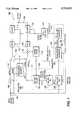
- FIG. 1depicts a block diagram of a block-based coding system incorporating the dynamic rate controller of the present invention
- FIG. 2illustrate the affect of scene cuts upon an MPEG Group of Pictures (GOP);
- FIG. 3depicts the proper alignment of FIGS. 3A and 3B.
- FIG. 1depicts a block diagram of a block-based coding system 100 (specifically, an MPEG encoder) incorporating the present invention.
- the input signal, at port 102, to the systemis assumed to be a preprocessed image that has been partitioned into a plurality of blocks, where the blocks are sequentially provided as an input to the system.
- these blocks of pixelsare commonly known as macroblocks, e.g., a 16 ⁇ 16 pixel block.
- macroblockis intended to describe a block of pixels of any size that is used for the basis of motion compensation.
- the systemcomputes, from the system output signal, a series of predicted macroblocks (P). Each predicted macroblock is illustratively produced by decoding the output signal, at port 104, just as the receiver of the transmitted output signal would decode the received signal.
- Subtractor 106generates, on path 107, a residual signal (also referred to in the art as simply the residual or the residual macroblock) by subtracting the predicted macroblock from the input macroblock.
- the input macroblockis said to be motion compensated.
- the difference between the predicted macroblock and the input macroblockis substantial, the residuals are difficult to code. Consequently, the system is better off directly coding the input macroblock in lieu of coding the motion compensated residual macroblock.
- This selectionis known as a selection of the coding mode. Coding the input macroblock (I) is referred to as intra-coding, while coding the residuals is referred to as inter-coding. The selection between these two modes is known as the Intra-Inter-Decision (IID).
- the IIDis made by the IID circuit 110, which sets the coding mode switch 108.
- the IIDis computed by first computing the variance of the residual macroblock (Var R) and the variance of the input macroblock (Var I).
- the coding decisionis based on these values. There are several functions that can be used to make this decision. For example, using the simplest function, if Var R is less than Var I, the IID selects the Intermode. Conversely, if Var I is less than Var R, the IID selects the Intramode.
- the selected blockis processed in a discrete cosine transform (DCT) block 112.
- the DCTproduces coefficients representing the input signal to the DCT.
- the quantizer 114quantizes the coefficients to produce the output block at port 104.
- the dynamic rate controller 116 of the present inventioncontrols the quantization scale (step size) used to quantize the coefficients.
- the rate controlleralso controls the number of DCT coefficients that are coded by the system. The details of the rate control block are discussed with respect to FIG. 3 below.
- the encoderneeds access to the decoded images.
- the quantizer 114 outputis passed through both the inverse quantizer 118 and inverse DCT 120.
- the output of the inverse DCTis ideally identical to the input to the DCT 112.
- the decoded macroblockis produced by summing the output of the inverse DCT and the predicted macroblock.
- the decoded macroblockis simply the output of the inverse DCT.
- the decoded macroblocksare then stored in the frame store 124.
- the frame storeaccumulates a plurality of these "reconstructed" macroblocks that constitute an entire reconstructed frame of image information.
- the motion vector predictor 126uses the reconstructed frame to produce motion vectors that are used in generating predicted macroblocks for forthcoming input images.
- the motion vector predictor 126comprises three components: a full-pel motion estimator 128, a half-pel motion estimator 130, and a motion mode block 132.
- the full-pel motion estimator 128is a "coarse" motion vector generator that searches for a coarse match between a macroblock in a previous image and the present input macroblock.
- the previous imageis referred to as an anchor image.
- the anchor imageis what is known as an I or P frame within an image sequence known as a Group Of Pictures (GOP).
- the motion vectoris a vector representing the relative position where a coarse match was found between the two macroblocks.
- the coarse motion vector generatorproduces a motion vector that is accurate to one picture element (pel).
- the accuracy of the full-pel motion estimatoris improved in the half-pel motion estimator.
- the half-pel estimatoruses the full-pel motion vectors and the reconstructed macroblocks from the frame store 124 to compute motion vectors to half-pel accuracy.
- the half-pel motion vectorsare then sent to the motion modes block 132. Typically, there are multiple motion vectors related to each macroblock.
- the modes block 132selects the best motion vector for representing motion for each input macroblock.
- the full-pel estimatoris a computationally intensive task compared to the half-pel estimator. For this reason, in several implementations, it is computed separately on dedicated hardware. Often, all the full-pel motion vectors are computed before half-pel processing begins.
- the MPEG encoder system discussed aboveis a conventional system that is available as a set of integrated circuits as model L64120 from LSI Logic, Inc. of Milpitas, Calif. Importantly, this MPEG encoder stores an entire frame of full-pel motion vectors before the half-pel estimator begins operation.
- the concepts of Motion Estimation and Motion Compensationare based on an underlying assumption that the current picture is not very different from a previously occurring picture (the anchor image).
- the anchor picturesare substantially different from the current picture.
- the predicted macroblocksare very inaccurate and the residuals are large.
- the IIDselects the input macroblock (intra-mode) for coding in lieu of coding the residuals (inter-mode). It should be noted that this coding decision occurs even in the case where there is no scene change, and that a normally coded picture may contain a mixture of intra- and inter-coded macroblocks.
- the scene cut detector of the present inventionanalyzes all the macroblocks in a picture and then determines whether a scene cut has occurred. This is accomplished by counting the number of intra-coded macroblocks and comparing the count to a threshold level. Specifically, if the percentage of intra-coded macroblocks in any given frame exceeds the threshold level, that frame is deemed to follow a scene cut.
- the actual IID decisionis made after the half-pel motion vectors are generated and best motion vector is chosen. Since the full-pel estimator 128 generates motion vectors for the entire frame before the first macroblock is coded by the encoder, the inventive scene cut detector apparatus 134 monitoring these full-pel results is able to produce an IID estimate for all macroblocks, i.e., estimate that the IID would make when it does analyze the residuals.
- the scene cut detectorcomprises an IID estimator 136 connected in series to an intra-code macroblock counter 138.
- the counter 138generates a scene cut decision (a flag) indicating that the scene cut detector has determined that a scene cut has occurred.
- the inventive dynamic rate controlleradjusts the quantization scale of the quantizer, such that any possibility of a panic situation will be avoided.
- the dynamic rate controllerhas been provided a coding flag which warns of the impending scene cut prior to the frame following the scene cut being encoded.
- the dynamic rate controllercan readjust the bit allocations and monitor bit usage closely to prevent the possibility of a very large bit usage and a panic situation.
- the dynamic rate controller 116increases the bit allocation to the P picture, making sure that the new allocation does not underflow the buffer, and hence, maintain the picture quality.
- FIG. 2illustrates the P pictures (P 1 and P 3 ) that are worst affected by scene cuts 202 and 204 within an MPEG Group of Pictures (GOP) 200.
- GOPMPEG Group of Pictures
- FIG. 3depicts a detailed flow diagram illustrating the operation of the dynamic rate controller 116 of the present invention.
- the process 300begins at start block 302 and proceeds to step 304, where the process computes a nominal number of bits (T) to use to code the present picture. Also, step 304 initializes the increased bit allocation ( ⁇ T) to zero.
- the processqueries whether a scene cut flag has been issued by the scene cut detector. If the query is negatively answered, the process continues to step 308 where the present picture is coded with T bits (e.g., the nominal number of bits). Conversely, if the scene cut flag is detected, the process proceeds from step 306 to step 310.
- the processcomputes an increase ( ⁇ T) for the bit allocation (T).
- the bit allocation increaseis dependent upon several factors including: 1) the distance of the P picture that is about to be coded from the end of the group of pictures; 2) the number of I-mode macroblocks in the P picture; 3) ease of coding the I-mode macroblocks; and 4) the number of bits presently in the VBV.
- This informationis stored in various registers within the rate controller and are shown respectively as blocks 312, 314, 316 and 318 in FIG. 3. Each of the factors used to compute ⁇ T are discussed in detail below.
- the rate controllerdoes not require an increase in the bit allocation for the P picture.
- the bit allocation to the P pictureis made proportional to its distance from the I picture of the next group of pictures, i.e., the value of ⁇ T can be smaller as the P picture is closer to the end of the group of pictures.
- picture P 3 in FIG. 2which is the last P picture in the GOP.
- This P pictureis not used to predict any P pictures, and is used to predict only two B pictures that occurred just after the scene cut. This results in poor quality images for only the first two or three pictures in the new scene.
- Psycho-visual experimentshave shown that the human eye has trouble adjusting quickly to a new scene and that even if the first two or three pictures of the new scene have poor quality, the distortion is not noticeable to the human eye.
- the B pictures that follow P 3are predicted from the I picture (I 2 ), and hence, do not suffer significant degradation because of the scene cut. As such, the P 3 picture can be poorly coded without significantly degrading other pictures. Therefore, ⁇ T is set to a relatively small value for P pictures occurring near the end of a GOP.
- ⁇ Tcan be made proportional to the percentage of intra-coded macroblocks in the picture.
- the new sceneis so easy to code, i.e., it takes very few bits to code, that the actual number of bits used may be even less than the target bit allocation.
- the increase ( ⁇ T)can be small. For example, this can be accomplished by analyzing the variances of the macroblocks within the picture that is about to be coded and determining how easy the picture will be to code.
- ⁇ Tis defined depending on the potential for underflow. This potential for buffer underflow is easily computed by taking the difference between the number of bits in the VBV and the value of (T+ ⁇ T). Then, the value of ⁇ T is adjusted to avoid a negative (-) valued difference.
- the processcomputes the potential for underflow using the present value of ⁇ T.
- This stepcompares the VBV size with the current buffer fullness for this value of T increased by the value of ⁇ T. If the expected buffer fullness will come close to exceeding the VBV size, then the query at step 322 is affirmatively answered, and the process, at step 324, sets a possible underflow flag (also referred to as a possible panic flag).
- a possible underflow flagindicates that there is a potential that during the coding of the present picture that a panic situation may result. If a panic situation is not deemed imminent, the query at step 322 is negatively answered, and the process proceeds along the NO path to step 326.
- the processdetermines an initial quantizer scale that is intended to avoid underflowing the VBV.
- the processestablishes a number of DCT coefficients that will be coded at the initial quantizer scale. As discussed below, both the quantizer scale and the number of DCT coefficients that are coded are adjustable such that VBV underflow can be avoided.
- the processgenerates a target bit utilization profile.
- this utilization profileis pre-defined depending on the type of picture that is being coded, i.e., whether it is a P picture, a B picture or an I picture.
- the utilization profileis linear across the entire picture coding.
- the profilemay be non-linear allowing for more or less bits to be used at some points in the image than at other points. As such, the center of any given picture may be allocated more bits or a finer quantization scale than are allocated to outer lying areas of the picture.
- Another alternativeis to dynamically generate the target bit utilization profile by using information gathered from coding previous pictures of the same type.
- the actual target bit profile that is used to code the previous P picturemay be used as the target bit utilization profile for the present P picture.
- the processbegins coding the picture.
- the actual bit utilizationis compared to the target bit utilization profile after each macroblock is coded.
- the processadjusts the quantizer scale as needed to ensure that the actual bit utilization conforms to the target bit utilization profile.
- the speed at which the adjustment of the quantizer scale is accomplishedcan be varied depending upon the difference between the actual bit utilization profile and the target bit utilization profile. In other words, the response could be fast for large differences between the two profiles, or slowed for smaller differences between the two profiles.
- the response speedalso may depend upon whether the potential panic flag is set. For example, if both the potential panic flag and the scene cut flag are set, the number of bits used to code the next picture must be strictly controlled or an underflow situation is possible. Thus, when both these flags are set, the invention strictly controls bit utilization and the response speed of the quantization scale changes. In addition to adjusting the quantizer scale, the DCT coefficients that are coded can be changed as well. For example, if the actual bit utilization profile begins to substantially diverge from the target bit utilization profile and it is expected that the actual bit utilization will exceed the VBV (i.e., the potential panic flag is set). The higher ordered DCT coefficients can be dropped and not coded.
- the number of DCT coefficients that are codedwill depend upon the degree to which the target bit utilization profile will be exceeded. Typically, the number of DCT coefficients is only adjusted when both the possible panic flag is set in step 324 and a scene cut flag is identified in step 306.
- step 338the process queries whether all of the macroblocks for the present picture have been coded. If the query is negatively answered, the process continues along the NO path to step 332 where the next macroblock is coded. If the query in step 338 is affirmatively answered, the process continues to step 340 where the coding process is stopped.
- the foregoing rate control processattempts to equalize the overall quality of each of the pictures in a sequence.
- the rate control processattempts to distribute errors throughout a number of images rather than have a substantial number of errors in any one image.
- the inventive rate controllerattempts to maintain the quality of different regions within a picture constant, such that within a given image, when coded, coding errors and anomalies do not all appear in one region of the image.
Landscapes
- Engineering & Computer Science (AREA)
- Multimedia (AREA)
- Signal Processing (AREA)
- Compression Or Coding Systems Of Tv Signals (AREA)
Abstract
Description
Claims (20)
Priority Applications (6)
| Application Number | Priority Date | Filing Date | Title |
|---|---|---|---|
| US08/606,622US5731835A (en) | 1996-02-26 | 1996-02-26 | Dynamic coding rate control in a block-based video coding system |
| DE69735756TDE69735756T2 (en) | 1996-02-26 | 1997-02-26 | DYNAMIC CODING RATE CONTROL IN A BLOCK BASED VIDEO CODING SYSTEM |
| PCT/US1997/002564WO1997031481A1 (en) | 1996-02-26 | 1997-02-26 | Dynamic coding rate control in a block-based video coding system |
| JP9530284AJP2000505615A (en) | 1996-02-26 | 1997-02-26 | Dynamic coding rate control in block-based video coding systems |
| KR10-1998-0706666AKR100366426B1 (en) | 1996-02-26 | 1997-02-26 | Dynamic coding rate control in a block-based video coding system |
| EP97907684AEP0883963B1 (en) | 1996-02-26 | 1997-02-26 | Dynamic coding rate control in a block-based video coding system |
Applications Claiming Priority (1)
| Application Number | Priority Date | Filing Date | Title |
|---|---|---|---|
| US08/606,622US5731835A (en) | 1996-02-26 | 1996-02-26 | Dynamic coding rate control in a block-based video coding system |
Publications (1)
| Publication Number | Publication Date |
|---|---|
| US5731835Atrue US5731835A (en) | 1998-03-24 |
Family
ID=24428738
Family Applications (1)
| Application Number | Title | Priority Date | Filing Date |
|---|---|---|---|
| US08/606,622Expired - LifetimeUS5731835A (en) | 1996-02-26 | 1996-02-26 | Dynamic coding rate control in a block-based video coding system |
Country Status (6)
| Country | Link |
|---|---|
| US (1) | US5731835A (en) |
| EP (1) | EP0883963B1 (en) |
| JP (1) | JP2000505615A (en) |
| KR (1) | KR100366426B1 (en) |
| DE (1) | DE69735756T2 (en) |
| WO (1) | WO1997031481A1 (en) |
Cited By (28)
| Publication number | Priority date | Publication date | Assignee | Title |
|---|---|---|---|---|
| US6011589A (en)* | 1996-09-03 | 2000-01-04 | Mitsubishi Denki Kabushiki Kaisha | Picture coding device where the quantization step is adjusted in response to a motion vector |
| US6185253B1 (en)* | 1997-10-31 | 2001-02-06 | Lucent Technology, Inc. | Perceptual compression and robust bit-rate control system |
| US6215820B1 (en)* | 1998-10-12 | 2001-04-10 | Stmicroelectronics S.R.L. | Constant bit-rate control in a video coder by way of pre-analysis of a slice of the pictures |
| US6243497B1 (en)* | 1997-02-12 | 2001-06-05 | Sarnoff Corporation | Apparatus and method for optimizing the rate control in a coding system |
| US6332002B1 (en)* | 1997-11-01 | 2001-12-18 | Lg Electronics Inc. | Motion prediction apparatus and method |
| WO2002030126A1 (en)* | 2000-10-06 | 2002-04-11 | St Microelectronics Asia Pacific (Pte) Ltd | System and method of bit allocation in scene change situations |
| US20030012278A1 (en)* | 2001-07-10 | 2003-01-16 | Ashish Banerji | System and methodology for video compression |
| US20030058947A1 (en)* | 2001-09-26 | 2003-03-27 | Peterson Richard Mateer | Scene cut detection in a video bitstream |
| US20030138047A1 (en)* | 1999-07-28 | 2003-07-24 | Michael Orchard | Method and apparatus for accomplishing multiple description coding for video |
| US20030169811A1 (en)* | 2001-03-30 | 2003-09-11 | Takuya Kitamura | Image signal quantizing device and its method |
| US6766098B1 (en)* | 1999-12-30 | 2004-07-20 | Koninklijke Philip Electronics N.V. | Method and apparatus for detecting fast motion scenes |
| US6778706B1 (en)* | 1999-07-07 | 2004-08-17 | Lg Electronics Inc. | Image compression method for video decoding based on motion compensation |
| US20050105615A1 (en)* | 2003-11-13 | 2005-05-19 | Khaled El-Maleh | Selective and/or scalable complexity control for video codecs |
| US6937653B2 (en) | 2000-06-28 | 2005-08-30 | Hyundai Electronics Industries, Co., Ltd. | Rate control apparatus and method for real-time video communication |
| US20050201627A1 (en)* | 2004-03-11 | 2005-09-15 | Yi Liang | Methods and apparatus for performing fast mode decisions in video codecs |
| US20050201460A1 (en)* | 2004-03-10 | 2005-09-15 | Lg Electronics Inc. | System and method for controlling bit rate of an image |
| US20060239348A1 (en)* | 2005-04-25 | 2006-10-26 | Bo Zhang | Method and system for encoding video data |
| US20070122047A1 (en)* | 2004-04-20 | 2007-05-31 | Sony Corporation | Data processing apparatus and method and encoding device of same |
| US7372903B1 (en) | 1997-07-10 | 2008-05-13 | Mediatek, Inc. | Apparatus and method for object based rate control in a coding system |
| US20100172410A1 (en)* | 2009-01-07 | 2010-07-08 | Sony Corporation | Encoding device, method for adjusting target amount of code and record medium |
| US20100208805A1 (en)* | 2009-02-13 | 2010-08-19 | Xiang Yu | Adaptive quantization with balanced pixel-domain distortion distribution in image processing |
| US20100208804A1 (en)* | 2009-02-13 | 2010-08-19 | Xiang Yu | Modified entropy encoding for images and videos |
| US7856054B1 (en)* | 2003-11-14 | 2010-12-21 | Apple Inc. | Scene change identification during encoding of compressed video |
| US20110051809A1 (en)* | 2009-09-02 | 2011-03-03 | Sony Computer Entertainment Inc. | Scene change detection |
| WO2012047194A1 (en)* | 2010-10-04 | 2012-04-12 | Vidyo, Inc. | Automatic temporal layer bit allocation |
| US8537900B2 (en) | 2010-10-04 | 2013-09-17 | Vidyo, Inc. | Automatic temporal layer bit allocation |
| CN113377045A (en)* | 2021-06-08 | 2021-09-10 | 广东三姆森科技股份有限公司 | Multi-path position comparison output device based on FPGA |
| CN116248895A (en)* | 2023-05-06 | 2023-06-09 | 上海扬谷网络科技有限公司 | Video cloud transcoding method and system for virtual reality panorama roaming |
Families Citing this family (4)
| Publication number | Priority date | Publication date | Assignee | Title |
|---|---|---|---|---|
| US6563549B1 (en)* | 1998-04-03 | 2003-05-13 | Sarnoff Corporation | Method and apparatus for adaptively encoding an information stream |
| CN109218724B (en) | 2017-07-06 | 2020-08-04 | 腾讯科技(深圳)有限公司 | Data encoding method and device, storage equipment and terminal equipment |
| CN108200431B (en)* | 2017-12-08 | 2021-11-16 | 重庆邮电大学 | Bit allocation method for video coding code rate control frame layer |
| US10880354B2 (en)* | 2018-11-28 | 2020-12-29 | Netflix, Inc. | Techniques for encoding a media title while constraining quality variations |
Citations (7)
| Publication number | Priority date | Publication date | Assignee | Title |
|---|---|---|---|---|
| US5134476A (en)* | 1990-03-30 | 1992-07-28 | At&T Bell Laboratories | Video signal encoding with bit rate control |
| US5231484A (en)* | 1991-11-08 | 1993-07-27 | International Business Machines Corporation | Motion video compression system with adaptive bit allocation and quantization |
| US5253059A (en)* | 1992-05-15 | 1993-10-12 | Bell Communications Research, Inc. | Method and circuit for adjusting the size of a video frame |
| US5440345A (en)* | 1992-07-17 | 1995-08-08 | Kabushiki Kaisha Toshiba | High efficient encoding/decoding system |
| US5491513A (en)* | 1993-06-16 | 1996-02-13 | Intel Corporation | Bit rate controller for encoding video signals |
| US5576767A (en)* | 1993-02-03 | 1996-11-19 | Qualcomm Incorporated | Interframe video encoding and decoding system |
| US5594504A (en)* | 1994-07-06 | 1997-01-14 | Lucent Technologies Inc. | Predictive video coding using a motion vector updating routine |
- 1996
- 1996-02-26USUS08/606,622patent/US5731835A/ennot_activeExpired - Lifetime
- 1997
- 1997-02-26WOPCT/US1997/002564patent/WO1997031481A1/enactiveIP Right Grant
- 1997-02-26JPJP9530284Apatent/JP2000505615A/ennot_activeCeased
- 1997-02-26EPEP97907684Apatent/EP0883963B1/ennot_activeExpired - Lifetime
- 1997-02-26KRKR10-1998-0706666Apatent/KR100366426B1/ennot_activeExpired - Lifetime
- 1997-02-26DEDE69735756Tpatent/DE69735756T2/ennot_activeExpired - Lifetime
Patent Citations (7)
| Publication number | Priority date | Publication date | Assignee | Title |
|---|---|---|---|---|
| US5134476A (en)* | 1990-03-30 | 1992-07-28 | At&T Bell Laboratories | Video signal encoding with bit rate control |
| US5231484A (en)* | 1991-11-08 | 1993-07-27 | International Business Machines Corporation | Motion video compression system with adaptive bit allocation and quantization |
| US5253059A (en)* | 1992-05-15 | 1993-10-12 | Bell Communications Research, Inc. | Method and circuit for adjusting the size of a video frame |
| US5440345A (en)* | 1992-07-17 | 1995-08-08 | Kabushiki Kaisha Toshiba | High efficient encoding/decoding system |
| US5576767A (en)* | 1993-02-03 | 1996-11-19 | Qualcomm Incorporated | Interframe video encoding and decoding system |
| US5491513A (en)* | 1993-06-16 | 1996-02-13 | Intel Corporation | Bit rate controller for encoding video signals |
| US5594504A (en)* | 1994-07-06 | 1997-01-14 | Lucent Technologies Inc. | Predictive video coding using a motion vector updating routine |
Cited By (54)
| Publication number | Priority date | Publication date | Assignee | Title |
|---|---|---|---|---|
| US6011589A (en)* | 1996-09-03 | 2000-01-04 | Mitsubishi Denki Kabushiki Kaisha | Picture coding device where the quantization step is adjusted in response to a motion vector |
| US6243497B1 (en)* | 1997-02-12 | 2001-06-05 | Sarnoff Corporation | Apparatus and method for optimizing the rate control in a coding system |
| US7372903B1 (en) | 1997-07-10 | 2008-05-13 | Mediatek, Inc. | Apparatus and method for object based rate control in a coding system |
| US6185253B1 (en)* | 1997-10-31 | 2001-02-06 | Lucent Technology, Inc. | Perceptual compression and robust bit-rate control system |
| US6332002B1 (en)* | 1997-11-01 | 2001-12-18 | Lg Electronics Inc. | Motion prediction apparatus and method |
| US6215820B1 (en)* | 1998-10-12 | 2001-04-10 | Stmicroelectronics S.R.L. | Constant bit-rate control in a video coder by way of pre-analysis of a slice of the pictures |
| US6778706B1 (en)* | 1999-07-07 | 2004-08-17 | Lg Electronics Inc. | Image compression method for video decoding based on motion compensation |
| US20100329348A1 (en)* | 1999-07-27 | 2010-12-30 | Michael Orchard | Method and Apparatus for Accomplishing Multiple Description Coding for Video |
| US9826258B2 (en) | 1999-07-27 | 2017-11-21 | At&T Intellectual Property Ii, L.P. | Method and apparatus for multiple description video coding |
| US8199822B2 (en)* | 1999-07-27 | 2012-06-12 | At&T Intellectual Property Ii, L.P. | Method and apparatus for accomplishing multiple description coding for video |
| US8842733B2 (en) | 1999-07-27 | 2014-09-23 | At&T Intellectual Property Ii, L.P. | Method and apparatus for multiple description video coding |
| US20030138047A1 (en)* | 1999-07-28 | 2003-07-24 | Michael Orchard | Method and apparatus for accomplishing multiple description coding for video |
| US6920177B2 (en)* | 1999-07-28 | 2005-07-19 | At&T Corp. | Method and apparatus for accomplishing multiple description coding for video |
| US6766098B1 (en)* | 1999-12-30 | 2004-07-20 | Koninklijke Philip Electronics N.V. | Method and apparatus for detecting fast motion scenes |
| US6937653B2 (en) | 2000-06-28 | 2005-08-30 | Hyundai Electronics Industries, Co., Ltd. | Rate control apparatus and method for real-time video communication |
| US8369401B1 (en) | 2000-10-06 | 2013-02-05 | Stmicroelectronics Asia Pacific Pte Ltd. | System and method of bit allocation in scene change situations |
| WO2002030126A1 (en)* | 2000-10-06 | 2002-04-11 | St Microelectronics Asia Pacific (Pte) Ltd | System and method of bit allocation in scene change situations |
| US6865225B2 (en)* | 2001-03-30 | 2005-03-08 | Sony Corporation | Image signal quantizing device and its method |
| US20050157785A1 (en)* | 2001-03-30 | 2005-07-21 | Takuya Kitamura | Video signal quantizing apparatus and method thereof |
| US20050175094A1 (en)* | 2001-03-30 | 2005-08-11 | Takuya Kitamura | Video signal quantizing apparatus and method thereof |
| US20030169811A1 (en)* | 2001-03-30 | 2003-09-11 | Takuya Kitamura | Image signal quantizing device and its method |
| US7065138B2 (en) | 2001-03-30 | 2006-06-20 | Sony Corporation | Video signal quantizing apparatus and method thereof |
| US7145949B2 (en) | 2001-03-30 | 2006-12-05 | Sony Corporation | Video signal quantizing apparatus and method thereof |
| US9894379B2 (en)* | 2001-07-10 | 2018-02-13 | The Directv Group, Inc. | System and methodology for video compression |
| US20030012278A1 (en)* | 2001-07-10 | 2003-01-16 | Ashish Banerji | System and methodology for video compression |
| KR100920096B1 (en)* | 2001-09-26 | 2009-10-01 | 톰슨 라이센싱 | Method for detecting scene cuts in an mpeg video bitstream |
| US20030058947A1 (en)* | 2001-09-26 | 2003-03-27 | Peterson Richard Mateer | Scene cut detection in a video bitstream |
| US6996183B2 (en) | 2001-09-26 | 2006-02-07 | Thomson Licensing | Scene cut detection in a video bitstream |
| WO2003028236A1 (en)* | 2001-09-26 | 2003-04-03 | Thomson Licensing S.A. | Scene cut detection in a video bitstream |
| US20050105615A1 (en)* | 2003-11-13 | 2005-05-19 | Khaled El-Maleh | Selective and/or scalable complexity control for video codecs |
| CN101459844B (en)* | 2003-11-13 | 2013-06-12 | 高通股份有限公司 | Selective and/or scalable complexity control for video codecs |
| US9351013B2 (en)* | 2003-11-13 | 2016-05-24 | Qualcomm Incorporated | Selective and/or scalable complexity control for video codecs |
| CN101483774B (en)* | 2003-11-13 | 2012-09-05 | 高通股份有限公司 | Selective and/or scalable complexity control for video codecs |
| US7856054B1 (en)* | 2003-11-14 | 2010-12-21 | Apple Inc. | Scene change identification during encoding of compressed video |
| US20050201460A1 (en)* | 2004-03-10 | 2005-09-15 | Lg Electronics Inc. | System and method for controlling bit rate of an image |
| US20050201627A1 (en)* | 2004-03-11 | 2005-09-15 | Yi Liang | Methods and apparatus for performing fast mode decisions in video codecs |
| US7881386B2 (en)* | 2004-03-11 | 2011-02-01 | Qualcomm Incorporated | Methods and apparatus for performing fast mode decisions in video codecs |
| CN101015215B (en)* | 2004-03-11 | 2011-01-12 | 高通股份有限公司 | Method and apparatus for implementing fast mode decisions in a video codec |
| US20070122047A1 (en)* | 2004-04-20 | 2007-05-31 | Sony Corporation | Data processing apparatus and method and encoding device of same |
| US7711197B2 (en)* | 2004-04-20 | 2010-05-04 | Sony Corporation | Method and apparatus for determining a quantization scale of encoded data |
| US9667999B2 (en)* | 2005-04-25 | 2017-05-30 | Avago Technologies General Ip (Singapore) Pte. Ltd. | Method and system for encoding video data |
| US20060239348A1 (en)* | 2005-04-25 | 2006-10-26 | Bo Zhang | Method and system for encoding video data |
| US20100172410A1 (en)* | 2009-01-07 | 2010-07-08 | Sony Corporation | Encoding device, method for adjusting target amount of code and record medium |
| US8494047B2 (en) | 2009-01-07 | 2013-07-23 | Sony Corporation | Encoding device, method for adjusting target amount of code and record medium |
| US20100208804A1 (en)* | 2009-02-13 | 2010-08-19 | Xiang Yu | Modified entropy encoding for images and videos |
| US20100208805A1 (en)* | 2009-02-13 | 2010-08-19 | Xiang Yu | Adaptive quantization with balanced pixel-domain distortion distribution in image processing |
| US8934543B2 (en)* | 2009-02-13 | 2015-01-13 | Blackberry Limited | Adaptive quantization with balanced pixel-domain distortion distribution in image processing |
| US8345750B2 (en)* | 2009-09-02 | 2013-01-01 | Sony Computer Entertainment Inc. | Scene change detection |
| US20110051809A1 (en)* | 2009-09-02 | 2011-03-03 | Sony Computer Entertainment Inc. | Scene change detection |
| US9325989B2 (en) | 2010-10-04 | 2016-04-26 | Vidyo, Inc. | Automatic temporal layer bit allocation |
| US8537900B2 (en) | 2010-10-04 | 2013-09-17 | Vidyo, Inc. | Automatic temporal layer bit allocation |
| WO2012047194A1 (en)* | 2010-10-04 | 2012-04-12 | Vidyo, Inc. | Automatic temporal layer bit allocation |
| CN113377045A (en)* | 2021-06-08 | 2021-09-10 | 广东三姆森科技股份有限公司 | Multi-path position comparison output device based on FPGA |
| CN116248895A (en)* | 2023-05-06 | 2023-06-09 | 上海扬谷网络科技有限公司 | Video cloud transcoding method and system for virtual reality panorama roaming |
Also Published As
| Publication number | Publication date |
|---|---|
| WO1997031481A1 (en) | 1997-08-28 |
| KR19990087265A (en) | 1999-12-15 |
| DE69735756T2 (en) | 2007-01-04 |
| KR100366426B1 (en) | 2003-04-21 |
| JP2000505615A (en) | 2000-05-09 |
| EP0883963B1 (en) | 2006-04-26 |
| DE69735756D1 (en) | 2006-06-01 |
| EP0883963A1 (en) | 1998-12-16 |
| EP0883963A4 (en) | 2001-01-17 |
Similar Documents
| Publication | Publication Date | Title |
|---|---|---|
| US5731835A (en) | Dynamic coding rate control in a block-based video coding system | |
| KR100382676B1 (en) | Method and apparatus for detecting scene cuts in a block-based video coding system | |
| US6654417B1 (en) | One-pass variable bit rate moving pictures encoding | |
| US5878166A (en) | Field frame macroblock encoding decision | |
| US5854658A (en) | Statistical multiplexing system which encodes a sequence of video images using a plurality of video encoders | |
| US5682204A (en) | Video encoder which uses intra-coding when an activity level of a current macro-block is smaller than a threshold level | |
| US6529631B1 (en) | Apparatus and method for optimizing encoding and performing automated steerable image compression in an image coding system using a perceptual metric | |
| EP1068736B1 (en) | Method and apparatus for performing adaptive encoding rate control of a video information stream including 3:2 pull-down video information | |
| US6678322B1 (en) | Video data coding device, video data coding method, video data transmitting device, and video data recording medium | |
| US6122400A (en) | Compression encoder bit allocation utilizing colormetric-adaptive weighting as in flesh-tone weighting | |
| EP1086593B1 (en) | Sequence adaptive bit allocation for pictures encoding | |
| US7373004B2 (en) | Apparatus for constant quality rate control in video compression and target bit allocator thereof | |
| US7675971B2 (en) | Moving picture encoding apparatus and method, computer program and computer-readable storage medium | |
| EP1077000B1 (en) | Conditional masking for video encoder | |
| US8081679B2 (en) | Image processing apparatus | |
| US20090116555A1 (en) | Image encoding apparatus, method of controlling the same, and computer program | |
| US20040233984A1 (en) | Apparatus for variable bit rate control in video compression and target bit allocator thereof | |
| JP3428332B2 (en) | Image encoding method and apparatus, and image transmission method | |
| KR100317355B1 (en) | System for encoding motion picture video signals | |
| US20070025440A1 (en) | Video encoding method and device | |
| KR100761475B1 (en) | Video display device and its quality improvement method | |
| JP2008005536A (en) | Method and apparatus for detecting scene cuts in block-based video coding system | |
| KR20070029109A (en) | Video encoding method and device | |
| KR20050076245A (en) | Method for controlling transmission bit-rate |
Legal Events
| Date | Code | Title | Description |
|---|---|---|---|
| AS | Assignment | Owner name:DAVID SARNOFF RESEARCH CENTER, INC., NEW JERSEY Free format text:ASSIGNMENT OF ASSIGNORS INTEREST;ASSIGNOR:KUCHIBHOTLA, PRASHANTH;REEL/FRAME:008326/0013 Effective date:19960509 | |
| STCF | Information on status: patent grant | Free format text:PATENTED CASE | |
| AS | Assignment | Owner name:SARNOFF CORPORATION, NEW JERSEY Free format text:MERGER;ASSIGNOR:DAVID SARNOFF RESEARCH CENTER, INC.;REEL/FRAME:009912/0460 Effective date:19970404 | |
| FEPP | Fee payment procedure | Free format text:PAYOR NUMBER ASSIGNED (ORIGINAL EVENT CODE: ASPN); ENTITY STATUS OF PATENT OWNER: LARGE ENTITY | |
| FEPP | Fee payment procedure | Free format text:PAYER NUMBER DE-ASSIGNED (ORIGINAL EVENT CODE: RMPN); ENTITY STATUS OF PATENT OWNER: LARGE ENTITY Free format text:PAYOR NUMBER ASSIGNED (ORIGINAL EVENT CODE: ASPN); ENTITY STATUS OF PATENT OWNER: LARGE ENTITY | |
| FPAY | Fee payment | Year of fee payment:4 | |
| AS | Assignment | Owner name:MEDIATEK, INC., TAIWAN Free format text:ASSIGNMENT OF ASSIGNORS INTEREST;ASSIGNOR:SARNOFF CORPORATION;REEL/FRAME:016283/0355 Effective date:20041022 | |
| FPAY | Fee payment | Year of fee payment:8 | |
| FPAY | Fee payment | Year of fee payment:12 |