US5731516A - System and method for monitoring a pneumatic tire - Google Patents
System and method for monitoring a pneumatic tireDownload PDFInfo
- Publication number
- US5731516A US5731516AUS08/642,156US64215696AUS5731516AUS 5731516 AUS5731516 AUS 5731516AUS 64215696 AUS64215696 AUS 64215696AUS 5731516 AUS5731516 AUS 5731516A
- Authority
- US
- United States
- Prior art keywords
- housing
- conductive
- pneumatic tire
- tire
- wheel
- Prior art date
- Legal status (The legal status is an assumption and is not a legal conclusion. Google has not performed a legal analysis and makes no representation as to the accuracy of the status listed.)
- Expired - Lifetime
Links
Images


Classifications
- H—ELECTRICITY
- H01—ELECTRIC ELEMENTS
- H01Q—ANTENNAS, i.e. RADIO AERIALS
- H01Q1/00—Details of, or arrangements associated with, antennas
- H01Q1/12—Supports; Mounting means
- H01Q1/22—Supports; Mounting means by structural association with other equipment or articles
- H01Q1/2208—Supports; Mounting means by structural association with other equipment or articles associated with components used in interrogation type services, i.e. in systems for information exchange between an interrogator/reader and a tag/transponder, e.g. in Radio Frequency Identification [RFID] systems
- H01Q1/2241—Supports; Mounting means by structural association with other equipment or articles associated with components used in interrogation type services, i.e. in systems for information exchange between an interrogator/reader and a tag/transponder, e.g. in Radio Frequency Identification [RFID] systems used in or for vehicle tyres
- B—PERFORMING OPERATIONS; TRANSPORTING
- B60—VEHICLES IN GENERAL
- B60C—VEHICLE TYRES; TYRE INFLATION; TYRE CHANGING; CONNECTING VALVES TO INFLATABLE ELASTIC BODIES IN GENERAL; DEVICES OR ARRANGEMENTS RELATED TO TYRES
- B60C23/00—Devices for measuring, signalling, controlling, or distributing tyre pressure or temperature, specially adapted for mounting on vehicles; Arrangement of tyre inflating devices on vehicles, e.g. of pumps or of tanks; Tyre cooling arrangements
- B60C23/02—Signalling devices actuated by tyre pressure
- B60C23/04—Signalling devices actuated by tyre pressure mounted on the wheel or tyre
- B60C23/0401—Signalling devices actuated by tyre pressure mounted on the wheel or tyre characterised by the type of alarm
- B—PERFORMING OPERATIONS; TRANSPORTING
- B60—VEHICLES IN GENERAL
- B60C—VEHICLE TYRES; TYRE INFLATION; TYRE CHANGING; CONNECTING VALVES TO INFLATABLE ELASTIC BODIES IN GENERAL; DEVICES OR ARRANGEMENTS RELATED TO TYRES
- B60C23/00—Devices for measuring, signalling, controlling, or distributing tyre pressure or temperature, specially adapted for mounting on vehicles; Arrangement of tyre inflating devices on vehicles, e.g. of pumps or of tanks; Tyre cooling arrangements
- B60C23/02—Signalling devices actuated by tyre pressure
- B60C23/04—Signalling devices actuated by tyre pressure mounted on the wheel or tyre
- B60C23/0408—Signalling devices actuated by tyre pressure mounted on the wheel or tyre transmitting the signals by non-mechanical means from the wheel or tyre to a vehicle body mounted receiver
- B60C23/0422—Signalling devices actuated by tyre pressure mounted on the wheel or tyre transmitting the signals by non-mechanical means from the wheel or tyre to a vehicle body mounted receiver characterised by the type of signal transmission means
- B60C23/0433—Radio signals
- B—PERFORMING OPERATIONS; TRANSPORTING
- B60—VEHICLES IN GENERAL
- B60C—VEHICLE TYRES; TYRE INFLATION; TYRE CHANGING; CONNECTING VALVES TO INFLATABLE ELASTIC BODIES IN GENERAL; DEVICES OR ARRANGEMENTS RELATED TO TYRES
- B60C23/00—Devices for measuring, signalling, controlling, or distributing tyre pressure or temperature, specially adapted for mounting on vehicles; Arrangement of tyre inflating devices on vehicles, e.g. of pumps or of tanks; Tyre cooling arrangements
- B60C23/02—Signalling devices actuated by tyre pressure
- B60C23/04—Signalling devices actuated by tyre pressure mounted on the wheel or tyre
- B60C23/0491—Constructional details of means for attaching the control device
- B60C23/0494—Valve stem attachments positioned inside the tyre chamber
- B—PERFORMING OPERATIONS; TRANSPORTING
- B60—VEHICLES IN GENERAL
- B60C—VEHICLE TYRES; TYRE INFLATION; TYRE CHANGING; CONNECTING VALVES TO INFLATABLE ELASTIC BODIES IN GENERAL; DEVICES OR ARRANGEMENTS RELATED TO TYRES
- B60C23/00—Devices for measuring, signalling, controlling, or distributing tyre pressure or temperature, specially adapted for mounting on vehicles; Arrangement of tyre inflating devices on vehicles, e.g. of pumps or of tanks; Tyre cooling arrangements
- B60C23/02—Signalling devices actuated by tyre pressure
- B60C23/04—Signalling devices actuated by tyre pressure mounted on the wheel or tyre
- B60C23/0491—Constructional details of means for attaching the control device
- B60C23/0496—Valve stem attachments positioned outside of the tyre chamber
- G—PHYSICS
- G06—COMPUTING OR CALCULATING; COUNTING
- G06K—GRAPHICAL DATA READING; PRESENTATION OF DATA; RECORD CARRIERS; HANDLING RECORD CARRIERS
- G06K19/00—Record carriers for use with machines and with at least a part designed to carry digital markings
- G06K19/06—Record carriers for use with machines and with at least a part designed to carry digital markings characterised by the kind of the digital marking, e.g. shape, nature, code
- G06K19/067—Record carriers with conductive marks, printed circuits or semiconductor circuit elements, e.g. credit or identity cards also with resonating or responding marks without active components
- G06K19/07—Record carriers with conductive marks, printed circuits or semiconductor circuit elements, e.g. credit or identity cards also with resonating or responding marks without active components with integrated circuit chips
- G06K19/077—Constructional details, e.g. mounting of circuits in the carrier
- G06K19/07749—Constructional details, e.g. mounting of circuits in the carrier the record carrier being capable of non-contact communication, e.g. constructional details of the antenna of a non-contact smart card
- G06K19/07758—Constructional details, e.g. mounting of circuits in the carrier the record carrier being capable of non-contact communication, e.g. constructional details of the antenna of a non-contact smart card arrangements for adhering the record carrier to further objects or living beings, functioning as an identification tag
- G06K19/07764—Constructional details, e.g. mounting of circuits in the carrier the record carrier being capable of non-contact communication, e.g. constructional details of the antenna of a non-contact smart card arrangements for adhering the record carrier to further objects or living beings, functioning as an identification tag the adhering arrangement making the record carrier attachable to a tyre
Definitions
- the present inventionrelates to a system and method for monitoring a pneumatic tire.
- a sensor malfunctionmay lead to an unneeded visit to a service professional to diagnose and correct a non-existent problem. After repetitive false alarms, a vehicle operator may disregard an indication of a hazardous operating condition when one actually occurs. Similarly, a sensor which does not detect a faulty or inoperative vehicle system may lead to unnecessarily extensive repairs, or a potential safety hazard. Thus, the integrity of the system, and the resulting confidence of the operator in the system, depend upon the integrity of the sensors.
- An often overlooked vehicle component which is essential to proper vehicle operationis the pneumatic tire.
- An improperly inflated vehicle tiremay be manifested as reduced efficiency in gas milage, reduced performance in ride and handling, reduced performance in vehicle braking, premature wearing of the tire, or a more serious flat tire or blow-out, among other potential diminutions in vehicle performance or operating safety.
- Tire pressureis generally measured when the tires are originally inflated or when a tire is noticeably under-inflated.
- noticeable under-inflationis typically at an inflation pressure significantly lower than the optimal operating inflation pressure.
- the tirehas already been operated while improperly inflated, leading to any of the number of problems noted above.
- a number of prior art deviceshave attempted to solve the problem of improperly inflated vehicle tires by providing an automatic tire pressure monitoring system.
- these systemsmonitor tire parameters, such as temperature and pressure, and provide an indication to the vehicle operator if any of the vehicle tires are improperly inflated or a potential safety hazard exists due to severe under inflation (which may be a flat tire or a blow-out).
- Many of the prior art systemsprovide a remote sensor within each of the tires in addition to a transmitter for transmitting a signal to a centrally located receiving unit.
- each of the prior art systemshas succumbed to at least one of the many varied challenges imposed upon a sensor subjected to the incredibly harsh operating environment of a vehicle tire.
- a typical vehicle operating environmentis not particularly amenable to the transmission and reception of digital or analog signals. Since the transmitter is often located entirely within a vehicle tire, powered by a battery separate from the vehicle battery, the receiver must be especially sensitive to the detection of relatively weak signals present in an electrically noisy milieu. Furthermore, the various electrically conductive components found on a typical vehicle may facilitate electrical communication but tend to hinder radio wave transmissions. For example, while a steel-belted tire resists penetration by sharp objects, a signal transmitted from within the tire maybe severely attenuated by those very same steel belts.
- a vehicle tire sensormust tolerate a wide range of temperature variations. Furthermore, a vehicle tire sensor must perform reliably under significant shock impacts and vibrations, a varying centrifugal force, and a constant applied pressure. Many of the currently available pressure sensors experience inelastic deformation of their microstructures which is manifested as a significant drift when subjected to a constant load. For example, one such sensor may drift almost 25% from its original reading when subjected to a constant load for only one (1) week.
- a sensoris externally mounted, or has an externally mounted antenna, it is subjected to even greater requirements due to exposure to the elements including water, mud, snow, ice, and the like.
- an externally mounted componentmust resist contamination by dirt and debris while also functioning reliably under conditions adverse to radio frequency (RF) transmissions.
- RFradio frequency
- an externally mounted antennashould transmit a detectable signal while immersed in water, snow, or mud, especially for commercial applications which frequently encounter such unfavorable conditions.
- the transmitting unitincluding the battery
- battery replacementrequires dismounting of the vehicle tire from the wheel.
- dismounting of the tireis also required to reprogram the monitoring device to recognize a different tire location, such as when tires ere rotated. Dismounting may also be required to determine if the monitoring device is operating correctly. The inconvenience and increased cost associated with such a device often outweighs the benefits associated with proper inflation of the vehicle tires.
- some prior art devicestransmit a signal only when improper inflation is detected.
- Other devicesuse the centrifugal force created by rotation of the tire to activate the tire monitoring device.
- These types of systemsallow a window of opportunity for undetected damaging operation to occur. For example, a centrifugally-actuated system would not alert an operator to a flat tire until the vehicle reached a predetermined operating speed. This may result in additional damage to the flat tire.
- a system which only detects a flat tirewould allow operation of an improperly inflated tire which was not yet flat but which could lead to premature tire wear requiring replacement.
- some prior art systemstransmit a digital code representing at least one parameter of the tire.
- U.S. Pat. No. 5,231,872 to Bowler et al.transmits a code representing an instantaneous signal value which includes an identification code and a plurality of receiver resynchronization codes for resynchronizing the central receiving unit.
- Such systemsare unnecessarily complex and result in higher manufacturing, assembly, and maintenance costs.
- transmission of an instantaneous signalmay lead to false alarms since tire inflation pressure may vary significantly during normal operation. For example, tire inflation may vary up to 7 psi between a tire exposed to direct sunlight and a tire on the same axle which is in the shade.
- Another object of the present inventionis to provide a pressure sensor for use in a pneumatic tire monitoring system which does not experience significant drift when subjected to a constant load.
- a further object of the present inventionis to provide a pneumatic tire monitoring system which includes a reliable communication link between a number of vehicle tire sensors end a centrally located receiving unit which functions properly when subjected to adverse conditions.
- Another object of the present inventionis to provide a pneumatic tire monitoring system which utilizes a wheel rim as an antenna to communicate between a centrally located processing unit end remotely located vehicle tire sensing units.
- An additional object of the present inventionis to provide a pneumatic tire monitoring system which tolerates vibrations, shock impacts, and various other disturbances incurred over the useful life of a vehicle.
- Still another object of the present inventionis to provide an ultra-low-power, efficient transmitter for use in a pneumatic tire monitoring system so as to significantly extend the useful battery life.
- a further object of the present inventionis to provide a pneumatic tire monitoring system which includes a multi-purpose processing unit which communicates with various other vehicle systems and subsystems.
- Yet another object of the present inventionis to provide a communication protocol for use with a pneumatic tire monitoring system which may be easily detected in the presence of electromagnetic noise and competing signal transmissions.
- a still further object of the present inventionis to provide a pneumatic tire monitoring system which includes aesthetically pleasing, externally mounted tire sensing apparatus.
- An additional object of the present inventionis to provide a pneumatic tire monitoring system which provides an accurate indication of average tire pressure so as to minimize concern of a vehicle operator to normal variations in tire inflation pressure.
- the present inventionprovides a method for monitoring a parameter of a vehicle tire.
- the methodcomprises generating a signal responsive to a parameter of the tire end conditioning the generated signal for transmission from the conductive wheel.
- the methodfurther comprises transmitting the conditioned signal via the conductive wheel so as to reduce a frequency shift induced by rotation of the wheel, receiving the transmitted signal, and monitoring the tire parameter by monitoring the received signal.
- the present inventionprovides a system for implementing the method for monitoring a parameter of a tire mounted on a conductive wheel.
- the systemcomprises a sensor for sensing a tire parameter and generating a signal indicative thereof, a transmitter in electrical communication with the sensor, a generally circular antenna which rotates with the tire, the antenna being in electrical communication with the transmitter for transmitting the generated signal, and a receiver for receiving the transmitted signal and monitoring the tire parameter by monitoring the received signal.
- FIG. 1presents a block diagram representation of one embodiment of a pneumatic tire monitoring system according to the present invention
- FIGS. 2a-2hillustrate a pressure sensor for use with a pneumatic tire monitoring system according to the present invention
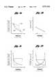
- FIGS. 3a-3dillustrate the pressure resistance characteristics of the sensors illustrated in FIGS. 2a-2d;
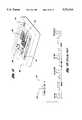
- FIG. 4is a sectional view of an externally mounted transponder for use with a pneumatic tire monitoring system according to the present invention
- FIG. 5is a sectional view of an alternative embodiment of an externally mounted transponder for use with a pneumatic tire monitoring system according to the present invention
- FIG. 6is a sectional view of another alternative embodiment of an externally mounted transponder for use with a pneumatic tire monitoring system according to the present invention.
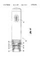
- FIG. 7is a sectional view of an internally mounted transponder for use with a pneumatic tire monitoring system according to the present invention.
- FIG. 8is a circuit schematic illustrating components included in a super regenerative receiver for use with a pneumatic tire monitoring system according to the present invention
- FIG. 9is a pictorial/schematic diagram of an integrated circuit end supporting components disposed within the transponders of FIGS. 5-7 according to the present invention.
- FIGS. 10a-10care pictorial/schematic representations of alternative embodiments of a receiving unit for use in a pneumatic tire monitoring system according to the present invention.
- FIG. 11illustrates an alternative display unit for use with the receiving units of FIGS. 10a-10c according to the present invention
- FIG. 12illustrates a prior art binary signaling strategy
- FIG. 13illustrates a trinary signaling strategy for use with a pneumatic tire monitoring system according to the present invention
- FIG. 14illustrates a hand-held service tool for use with a pneumatic tire monitoring system according to the present invention
- FIG. 15is a circuit schematic for a compensation circuit for use with a pressure sensor constructed according to the present invention.
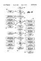
- FIG. 16is a flow chart illustrating operation of a main program for a pneumatic tire monitoring system according to the present invention.
- FIG. 17is a flow chart illustrating an interrupt program for a pneumatic tire monitoring system according to the present invention.
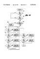
- FIGS. 18 and 19are flowcharts illustrating a tire reporting and alarm procedure for a pneumatic tire monitoring system according to the present invention.
- FIGS. 20 and 21are flow charts illustrating a lockout procedure for a pneumatic tire monitoring system according to the present invention.
- FIG. 1a block diagram of a pneumatic tire monitoring system, indicated generally by reference numeral 20 is illustrated.
- the systemincludes a transponder 22 and a receiving unit 24.
- a complete systemincludes one transponder 22 for each vehicle tire.
- transponder 22is entirely disposed within a vehicle tire (not shown).
- transponder 22is mounted externally on the valve stem of a vehicle tire, as explained in greater detail below.
- receiving unit 24is centrally located relative to all the transponders 22 for best reception of transmitted signals while also being located for convenient communication with an operator via user interface 26.
- transponder 22includes a pressure sensor 28 and may include various other sensors such as a temperature sensor 30.
- the sensorsgenerate signals responsive to the current operating conditions of an associated vehicle tires.
- the signalsare communicated to separate detectors (not shown) or to an integrated detector 32.
- Integrated detector 32processes the sensor signals which may include comparing the signals to various threshold levels as explained in greater detail below.
- Detector 32communicates with transmitter 34 which conditions the signals generated by the sensors for transmission, and broadcasts a signal representative of at least one of the vehicle tire parameters being monitored via antenna 36.
- antenna 36which rotates with the vehicle tire, should be oriented so that its center of mass lies along the axis of rotation of the vehicle wheel.
- antenna 36is the vehicle wheel itself.
- transmitter 34conditions the signals 30 generated by the sensors for transmission from the vehicle wheel as explained in greater detail below.
- the broadcast signalis received by a stationary antenna 38 which is in communication with receiver 40 of receiving unit 24.
- Receiver 40processes the received signal and exchanges information with an operator via user interface 26.
- user interface 26comprises an LCD display unit (such as the display unit illustrated in FIG. 11) for displaying the sensed tire pressure, a tire status indicator, or both to the user.
- Receiving unit 24is a multiple purpose device which may communicate with various other vehicle systems and subsystems and display additional information to a vehicle operator via user interface 26, as explained in greater detail below.
- FIGS. 2a-2da number of pressure sensors for use with a pneumatic tire monitoring system according to the present invention are shown. It will be appreciated by one of ordinary skill in this art, and other related arts, that the pressure sensor illustrated may be used in myriad other applications which require a repeatable, precise, and accurate indication of pressure (load or force).
- the pressure sensor of FIGS. 2a and 2bindicated generally by reference numeral 50, includes a conductive layer 52 deposited on a base layer 54.
- conductive layer 52has a hemispherical shape to provide a more linear response across the range of interest as explained in greater detail below.
- conductive layer 52is deposited onto base layer 54 utilizing a screening process or a vacuum deposition process which are well known in the art.
- base layer 54is formed from pure silicone rubber.
- conductive layer 52comprises approximately 20% activated N-type semiconductor material, 40% molybdenum disulfide (MoS 2 ), and approximately 40% alkyd or silicone binder.
- Conductive layer 52should have a minimum of 10% of activated N-type semiconductor material, although preferably, a range of 15% to 20% will be used to provide better stability. Once the concentration of the activated N-type semiconductor material is selected, the remaining two components comprise approximately equal contributions to the composition.
- compositionsmay be utilized to achieve the desired results. These compositions utilize similar resistive materials utilized in the manufacture of semiconductor integrated circuits. Many of these materials may be adapted for use in a pressure sensor constructed in accordance with the present invention to provide the operating characteristics described above.
- Some example compositionsinclude: 40% bismuth oxide, 10% activated N-type semiconductor, and 50% alkyd binder; 35% vanadium, 15% activated N-type semiconductor, and 50% alkyd binders 60% indium-tin, 15% activated N-type semiconductor, end 25% alkyd binders 50% titanium, 15% N-type semiconductor, and 35% alkyd binder.
- pressure sensor 50includes an alignment notch 56, or the like, to aid in the assembly of pressure sensor 50 into a transponder as illustrated in FIGS. 4-7.
- Pressure sensor 58 of FIG. 2dis utilized in conjunction with processing circuitry illustrated in FIG. 15 to provide a more linear resistance-to-pressure characteristic. Representative response characteristics for various sensors constructed according to the present invention are illustrated in FIGS. 3a-3d and explained in greater detail below.
- Pressure sensor 58includes two conductive layers 60, each having a quarter-spherical shape separated by a portion of the base layer 62 extending therebetween.
- conductive layers 60 and base layer 62are formed with similar techniques and compositions as conductive layer 52 and base layer 54, respectively, described above.
- An alignment notch 64is provided to aid in the assembly of pressure sensor 58 into a transponder.
- a disk-type pressure sensor 70includes a conductive layer 72 which has a composition similar to the conductive layer described for the sensors of FIGS. 2a and 2b.
- Conductive layer 72is separated from a fiberglass/ceramic base 76 by a Mylar spacer 74.
- Base 76includes thermal vents 78 end a conductive grid 80 comprised of two sections in electrical communication with terminals A and B, respectively.
- Conductive layer 72, Mylar spacer 74, end base 76include an alignment notch 82, or the like, to aid in alignment during manufacturing and assembly.
- Pressure sensor 70further includes a laser-trimmable resistor 84 (shown schematically in FIG. 2f) placed across terminals A end B to accommodate manufacturing variances in the conductive layer 72 so as to precisely calibrate the resistance of pressure sensor 70.
- conductive layer 72is deposited using a vacuum plasma deposition process.
- a silk screening processcould also be used but produces less uniform results.
- conductive grid 80is composed of a high conductivity material such as silver, carbon, copper, or the like.
- a dual-disk pressure sensor 90is illustrated in FIG. 2d.
- Sensor 90includes two semi-circular conductive layers 92 separated by a non-conductive portion therebetween. As with the pressure sensor of FIG. 2c and 2d, sensor 90 may be utilized in conjunction with processing circuitry as illustrated in FIG. 2i to provide a more linear pressure-resistance response characteristic as described in greater detail below.
- Conductive layer 92is separated from base layer 94 via Mylar spacer 96.
- Conductive layer 92, base layer 94, and Mylar spacer 96include alignment notch 98 to aid in alignment during manufacturing and assembly.
- Base layer 94includes a conductive grid, indicated generally by reference numeral 100, comprising three conductive portions corresponding to terminals C, D, and E, respectively.
- Pressure sensor 90also includes laser-trimmable resistors 102 and 104 (shown schematically in FIG. 2h) which are placed across terminals C and D, and D end E, respectively. Laser-trimmable resistors 102 and 104 accommodate manufacturing variances in the conductive layers 92 to allow precise calibration of pressure sensor 90.
- the sensors illustrated in FIGS. 2a and 2bare used in conjunction with a base plate having a conductive grid (such as base 76 and base 94, respectively, of FIGS. 2e and 2g).
- Conductive layers 52 and 60are in contact with their respective conductive grids.
- the elastic conductive layers 52 and 60are forced against their corresponding conductive grids such that the surface area of conductive layers 52 and 60 in contact with the conductive grids increases with the force exerted by pressure P.
- the resistance across terminals A and Bor across terminals C and D, or across terminals D and E) decreases yielding a resistance versus pressure characteristic as shown in FIGS.
- the sensor resistanceis determined in the transponder unit by providing a fixed capacitor and driving the conductive grid with a periodic signal.
- the time constant for the circuitvaries proportionally to the resistance of the sensor.
- the sensor resistancecan be precisely determined by measuring the period of the output signal.
- sensors 50, 58, 70 and 90provide a variable resistance as a function of pressure as illustrated schematically in FIGS. 2f and 2h and depicted graphically in FIGS. 3a-3d.
- Line 110 of FIG. 3arepresents an ideal resistance-to-pressure response which is linear across the entire range of interest.
- Line 112represents the change in resistance of a pressure sensor in response to an increase in applied pressure.
- Line 114represents the output of a compensation circuit, illustrated in FIG. 15, which compensates the resistance-pressure characteristic to more closely resemble an ideal linear response.
- a sine/cosine (or log/antilog) circuitis indicated generally by reference numeral 448.
- dual pressure sensor 450is connected with a common ground.
- Operational amplifier 452 and resistor 454invert their input signal produced by one of the variable resistance conductive layers of pressure sensor 450.
- Operational amplifier 456is connected with capacitor 458 in parallel with diode 460 providing feedback.
- Diodes 460 and 466are log diodes.
- the input signals to the circuitis provided by current flowing through the feedback paths, i.e. the leakage current of log diodes 460 and 466.
- the input signal produced by pressure sensor 450is exponential in character as illustrated in FIGS. 3a-3d.
- Capacitor 458 and log diode 460 in the feedback path of amplifier 456produces an output which is generally logarithmic in character. Thus, the output of amplifier 456 is linear across the range of interest.
- amplifier 462together with log diode 466 and capacitor 464 function in a manner similar to amplifier 456.
- the outputs of amplifiers 462 end 456provide the input to a difference amplifier 468 which helps to reduce or eliminate any hysteresis inherent in the pressure sensor 450.
- the output of compensation circuit 448which is the output of amplifier 468, is much closer to an ideal linear response without hysteresis as desired.
- the response characteristic illustrated in FIG. 3ccorresponds to a single disk pressure sensor, such as sensor 70 of FIG. 2e. Since conductive layer 72 of pressure sensor 70 is relatively flat, the resistance versus pressure characteristic is somewhat more non-linear than that produced by the hemispherical conductive layer utilized for sensors 50 and 58. However, a flat conductive layer such as conductive layer 72 or conductive layer 92, is less costly to produce.
- FIG. 3dillustrates complementary non-linear responses produced by a disk shaped dual pressure sensor, such as sensor 90 illustrated in FIG. 2g.
- An appropriate combination of these complementary responsesmay be utilized in conjunction with the processing circuitry described above to reduce the non-linearity of the resistance versus pressure response.
- Transponder 120includes a non-conductive cap 122 which is threadingly engaged to a non-conductive component retaining wall 124.
- O-ring 126isolates interior chamber 128 from the external environment.
- Non-conductive cap 122includes a non-conductive spacer 130 made of a suitable material, such as plastic, to exerts force on battery 132 for a proper electrical connection.
- battery 132is a single lithium cell which provides a nominal voltage of six (6) volts.
- a battery clip 134is biased to contact a positive terminal of battery 132 to provide power to printed circuit board (PCB) 136.
- PCBprinted circuit board
- Ground terminal 138is connected to the negative terminal of battery 132 via spring 140.
- PCB 136also includes an inductor 142, a surface mount inductor 144, end a connector 146.
- the PCB 136also contains an application-specific integrated circuit (ASIC) 147.
- PCB 136is connected to pressure sensor base layer 156 via a capacitor 148 end at least one conductor 150 (depending upon the particular sensor construction being utilized).
- a bushing 152is press-fit into housing 154 to retain base layer 156, Mylar spacer 158, end conductive layer 160.
- O-ring 164seals the interior chamber 165 between conductive layer 160 and push-pin 168.
- Bushing 166is press-fit into housing 154 and allows air to pass along push-pin 168 into interior chamber 165 when transponder 120 is threadingly engaged to a pneumatic tire valve stem (not shown).
- O-ring 170prevents air from escaping through the threaded portion of housing 152 when transponder 120 is coupled to a pneumatic tire valve stem.
- housing 154is made of a lightweight, electrically conductive material, such as aluminum or the like.
- Whisker connector 172is press-fit into an appropriate aperture along a threaded portion 174 of housing 154 to provide electrical conductivity between housing 154 and the transponder antenna which is preferably the wheel rim. It should be appreciated that the whisker functions only as an electrical connector end does not function as an antenna.
- whisker connector 172may be utilized to accommodate varying sizes of valve stems associated with various sizes of pneumatic tires.
- whisker connector 172could be en electrically conductive spring as illustrated in FIG. 5, or other similar electrically conductive device.
- Transponder 180for use in a pneumatic tire monitoring system according to the present invention is shown. Similar to the embodiment illustrated in FIG. 4, a non-conductive cap 182 is threadingly engaged to a non-conductive component retainer 184 with an air-tight seal being provided by O-ring 186. Battery 188 is connected in a similar fashion as the embodiment of FIG. 4 so as to prevent improper insertion of the battery from providing a reverse polarity voltage to the system.
- Transponder 180includes aground terminal 190 electrically connected to a printed circuit board 192.
- PCB 192includes an ASIC, as well as various other circuit components (not specifically illustrated).
- PCB 192is separated via spacer 194 from a base layer 196 which includes a laser-trimmable resistor 198 and a conductive grid 200.
- An electrically conductive ball 202, spring 204, and pin 206 in conjunction with external spring 208provide an electrical path to the transmitting/receiving antenna which is preferably the wheel rim (not shown).
- housing 210is constructed of a material which is high-strength, lightweight, and electrically insulating.
- Hemispherical conductive layer 212is deposited upon base layer 214 which is preferably composed of pure silicone rubber.
- Bushing 216provides a stable surface for base layer 214.
- an insert 218is constructed of a lightweight, durable material and is press-fit into housing 210 to increase the structural integrity of the threaded portion.
- O-ring 220prevents air from escaping through the threaded portion provided by insert 218 when transponder 188 is installed on a valve stem of a pneumatic vehicle tire (not shown).
- Push-pin 222is operative to engage a needle valve of a pneumatic tire (not shown) and allows pressurized air to exert a force on base layer 214.
- transponder 180is threadingly engaged with the valve stem of a pneumatic vehicle tire.
- Push-pin 222depresses a needle valve (not shown) within the valve stem of the vehicle tire to allow pressurized air to exert a force on base layer 214.
- This forceis transferred to conductive layer 212 so as to compress conductive layer 212 against conductive grid 200.
- Thisprovides a variable resistance indicative of the inflation pressure of the pneumatic tire as explained in detail above.
- FIG. 6another embodiment of an externally mounted transponder for use with a pneumatic tire monitoring system according to the present invention is shown.
- the alternative pressure sensor 180'utilizes a hemispherically-shaped pressure sensor similar to the embodiment illustrated in FIG. 5. However, this embodiment realizes an electrically conductive housing 230 in conjunction with a whisker connector 232 to create electrically conductive path to the antenna (not shown).
- Alternative pressure sensor 180'is otherwise identical in construction and function to pressure sensor 180 illustrated in FIG. 5 and described in detail above. Additional primed reference numerals have been omitted for the sake of clarity.
- Transponder 240includes a cap 242 threadingly engaged to a component-retaining member 244 and sealed from outside contaminants by O-ring 246.
- Cap 242includes a spacer 250 which is electrically insulating.
- a battery clip 252connects the positive terminal of the battery 248 to PCB 254.
- Housing 256includes a passage 258 to allow pressurized air access to conductive layer 260.
- a Mylar spacer 262separates conductive layer 260 from conductive grid 264 located on the bottom of PCB 254.
- Transponder 240also includes a spring 266 to provide electrical conductivity from the negative terminal of battery 248 to ground terminal 268.
- PCB 254includes an ASIC 270, an inductor 272, a laser-trimmable resistor 274, end a laser-trimmable inductor 276.
- Ground terminal 268encloses a surface acoustic wave (SAW) resonator or a laser-trimmable capacitor circuit (not shown) as described in greater detail below.
- SAWsurface acoustic wave
- housing 256extends through an appropriately sized aperture located in the rim of a wheel 278.
- Conductive rubber seals 280provide electrical conductivity from housing 256 to wheel rim 278 which functions as the antenna.
- a retaining washer 282 and nut 284engage the threaded portion of housing 256 to secure transponder 240 to wheel rim 278.
- a conventional needle pin end spring arrangement 286is disposed within the end of the valve stem to allow inflation or deflation of the tire.
- Housing 256 end rubber seals 280circumscribe channel 257 having a fiberoptic waveguide 259 disposed therein. Fiberoptic waveguide 259 is connected to PCB 254 to provide an additional communication path for exchanging diagnostic, maintenance, end history information, as well as allowing programming of the device as explained in greater detail below.
- FIG. 8a circuit schematic illustrating a receiver for use with a pneumatic tire monitoring system according to the present invention is shown.
- the circuit schematicillustrates the principal components utilized to implement a high sensitivity, high stability, low cost receiver.
- the receiverimplements a super-regenerative strategy with compensation.
- Antenna 302receives a transmitted electromagnetic signal.
- the transmitted signalmay originate from a transponder such as those illustrated in FIGS. 4-7, or another transmitting unit.
- receiver 300is tuned to detect pulses at a nominal frequency of 300 MHz and 90 MHz.
- a receive signalis amplified by a two-stage common base amplifier 304 implemented using two low-noise transistors 303 and 305.
- Isolating inductors 307 and 309reduce noise associated with power supply 306.
- Inductors 311 and 313are coupled out of phase to provide further stability to the system.
- inductors 311 and 313have a nominal value of 20 mH
- capacitor 315 and inductor 317are selected to tune the quenching frequency of the circuit.
- the nominal quenching frequency of the circuitis 100 Khz.
- An additional low noise transistor 319is provided to implement the super-regenerative detector to provide a relatively noise-free output signal at receiver output connector 308.
- FIG. 9a pictorial/schematic diagram illustrating the application specific integrated circuit (ASIC) end associated circuitry utilized in the various transponders of the present invention is shown.
- Resistor 321 and capacitor 323provide an RC time constant which controls reporting timer 320.
- reporting timer 320determines the frequency at which various information such as battery condition and pressure sensor readings, is transmitted to a receiving unit.
- a crystal 325controls the internal clock for ASIC 300 to provide date and time stamping functions. Crystal 325 also serves as an input to oscillator 322.
- Sensor 327is a variable resistance pressure sensor such as those illustrated in FIGS. 2a-2d. Sensor 327 is also connected to a coherent current device 310 which controls the current flowing through sensor 327.
- Resistors 329 and 331provide a voltage divider input to window comparator circuit 324 to control a lower threshold for reporting pressure information, as explained in greater detail below.
- Variable resistor 333is preferably a potentiometer which is user adjustable to control the upper threshold for the window comparator circuit 324. When a pneumatic tire is in its normal operating pressure range, the voltage across sensor 327 will be between the lower threshold determined by resistors 329 and 331, and the upper threshold determined by variable resistor 333. When the voltage of sensor 327 is below the lower threshold or above the upper threshold, the operating mode changes to alarm mode and reporting information is sent immediately rather than during the next interval scheduled by reporting timer 320.
- transmitting circuit 312the components contained within transmitting circuit 312 are located on a printed circuit board, such as PCB 254.
- antenna 314may be connected to the collector node of transistor 335.
- the transmitting circuit 312overcomes this problem by providing impedance matching using inductor 337 and resistor 339 and having antenna 314 connected therebetween. Resistor 339 is then connected to a center tap of inductor 341.
- inductor 337has a nominal value of 1,000 Nh and resistor 339 has a nominal value of 50 ⁇ .
- Capacitor 343is a laser-trimmable capacitor which is trimmed after manufacturing to precisely adjust the transmitting frequency of transmitting circuit 312.
- Capacitor 345provides a feedback path for transistor 335 which is a low-noise NPN-type transistor.
- antenna 314which is preferably a vehicle wheel rim.
- transmitting circuit 312accommodates various sizes of wheel rims having various impedances without modification.
- the systemis immune to local changes in capacitance due to capacitive coupling, such as when the vehicle wheel is in standing water or a user approaches the vehicle.
- a test pin 316is provided to connect the positive input of battery 318 to the test pin input of ASIC 300.
- a number of three-position jumpers 328are utilized to program the unique unit serial number during manufacturing. Each jumper input may be connected to a positive voltage (preferably 3 volts DC), ground, or left open. This provides 3 10 unique serial numbers for use by various transponders so as to minimize the possibility of receiving a signal from a transponder mounted on a different vehicle.
- a reed relay 347provides a serial input which is processed by logic 326 to select various programming modes. Alternatively, an optical link may be provided to accomplish this function, as explained in greater detail below.
- FIGS. 10a-10calternative embodiments of a transponder receiver for use with a pneumatic tire monitoring system according to the present invention are shown.
- Components illustrated in FIGS. 10b and 10cwhich are similar in construction and function to components illustrated in FIG. 10a are indicated by primed (xx') and double-primed (xx") reference numerals. Thus, the construction and operation of those components is described with reference to the unprimed reference numerals of FIG. 10a.
- the transponder receivermay utilize super-regenerative receiver circuitry 340 or, alternatively, superheterodyne receiver circuitry 342.
- the super-regenerative receiver circuitry 340includes a receiving antenna 344 coupled to a two-stage radio frequency (RF) amplifier 346 which amplifies the received signal.
- RFradio frequency
- Super-regenerative oscillator 348converts the frequency of the received signal which is then amplified by intermediate frequency (IF) amplifier 350 before it is communicated to integrated circuit 352.
- IFintermediate frequency
- superheterodyne receiver circuitry 342may be utilized which includes an antenna 354 for receiving the transmitted signal.
- the received signalis then amplified by a two-stage RF amplifier 356.
- the amplified signalis mixed by mixer 358 with a signal generated by SAW oscillator 360 to produce a signal having an intermediate frequency. This signal is then amplified by a two-stage IF amplifier 362 before it is communicated to integrated circuit 352.
- integrated circuit (IC) 352performs a number of system functions.
- IC 352contains a predetermined instruction set which is executed to effect various programming and control functions of the pneumatic tire monitoring system.
- Random Access Memory (RAM) within IC 352provides a data input buffer for received transmissions so that they may be recorded and stored for future processing.
- IC 352also contains data discrimination circuitry which filters out spurious signals which were not transmitted by a transponder associated with the system, or which were transmitted erroneously.
- IC 352also contains automatic gain control (AGC) circuitry end additional RF amplifying circuitry.
- AGCautomatic gain control
- an LCD display 364provides a graphical user interface to alert the user to properly inflated end/or improperly inflated tires.
- LCD display 364is coupled to IC 352 via current limiting resistors 351.
- LCD display 364includes an area 366 corresponding to each of the vehicle tires.
- Push button 353is utilized to select various operating modes and program the pneumatic tire monitoring system.
- a buzzer 355is provided to alert the vehicle operator of an abnormal operating condition.
- a silencing featureis also provided so that the buzzer does not distract the operator during an emergency situation, e.g. after a blow-out.
- the silencer featuremay be manually or automatically implemented as described in greater detail below.
- an optical link 366is provided so that the system may provide information to, or receive information from, various other vehicle subsystems.
- the transponder receiver illustratedfunctions as a multi-purpose receiver.
- Optical link 366includes a filter 368 for filtering light passing to optical transistor 369.
- filter 368has a relatively narrow bandwidth such that only those signals having a similar bandwidth are allowed to pass through filter 368 to optical transistor 369.
- Optical link 366also includes a light-emitting diode (LED) 371 for transmitting optical information.
- LEDlight-emitting diode
- fiberoptic link 366could be provided for transmitting and receiving optical information from various other vehicle systems and subsystems.
- a clock crystal 370is provided for date stamping of alarms end maintenance information.
- An alarm bufferis maintained within IC 352 which contains a predetermined number of the most recently activated alarm codes for diagnostic purposes.
- An oscillating circuit 372includes capacitors 373 and 375 as well as crystal 377 which provides the frequency of oscillation for the main logic of IC 352 end the data discrimination circuitry.
- the power conditioning and buffering circuitryis indicated generally in FIG. 10a by reference numeral 374.
- This circuitryincludes a standard fuse and magnetic overload protection (not shown) connected in series with connector 379.
- Element 381provides protection against voltage transients while capacitor 383 provides impedance matching.
- Voltage regulator 385 and filtering capacitor 387provide a filtered 9 volt analog power supply.
- Voltage regulator 389 and filtering capacitor 391provide a separate 5 volt digital power source.
- Diode 393protects the system from reverse polarity caused by an improperly installed battery 395. When properly installed, battery 395 provides efficient backup power for the system clock and RAM.
- FIG. 10bhas components similar to those described above and illustrated in FIG. 10a as indicated by the primed reference numerals.
- Push buttons 353'provide increased flexibility and selection of modes and features of the system.
- Display unit 364'includes a graphical display section as well as a numerical display section.
- display 364'could be integrated into other similar displays typically found on the instrument panel of a vehicle.
- other vehicle informationcould be transmitted to IC 352' via optical link 366' and displayed on display unit 364'.
- a compass indicating the current direction of travel of the vehiclecould be displayed on display unit 364'.
- Transistors 380are provided to control the additional LED's and seven-segment displays of display 364'.
- FIG. 10cindicates components similar to those previously described by double-primed reference numerals.
- an additional connector 382is provided as an interlace to other vehicle systems or subsystems.
- IC 352formats output to connector 382 in a standard or customized output protocol. Standard protocols such as SAE J1850 or SAE J1939 may be accommodated.
- Multipurpose display unit 388includes selection/programming buttons, such as mode button 390, which allow a user to set various system parameters and access predetermined system information.
- a seven segment numerical display area 392provides a numerical reading of the average pressure sued in the various vehicle tires.
- Display 388also includes an area for display of predetermined messages, such as message 394.
- a vent 396provides for transmission of an audible alarm signal generated by a buzzer (such as buzzer 355 of FIGS. 10a-10c) to alert the user to a particular system condition. The buzzer may be utilized as an alarm or during programming to provide audible feedback to the user while programming the system.
- Display unit 388also includes a graphical display area as indicated by reference numeral 398.
- the graphical display areaincludes an indicator corresponding to each of the vehicle tires which may include a spare tire in addition to the mounted vehicle tires.
- FIG. 12a prior art digital signaling strategy is illustrated.
- This strategyutilizes pulsewidth modulation (PWM) with binary symbols.
- PWMpulsewidth modulation
- a "0"is represented by a narrow pulse 400
- a "1”is represented by a relatively wider pulse 402.
- a predetermined number of sequential bitsform a data word.
- the data wordmay include data bits in addition to overhead bits, such as synchronization bits, error detection and correction bits, and the like.
- the signaling strategy illustrated in FIG. 12 having 16-bit data wordswill provide for up to 2 16 (65, 536) different combinations.
- a vehiclesuch as a tractor semi-trailer
- each wheelwould have 4096 possible unique identification codes.
- FIG. 13An alternative communications strategy according to the present invention is illustrated in FIG. 13. This strategy also utilizes PWM symbols. However, rather then utilizing binary symbols, the present invention utilizes trinary symbols. Thus, a "1" is represented by two wide pulses 410, a "0” is represented by two narrow pulses 412, and a “2" is represented by a long pulse followed by a short pulse. Thus, by utilizing only 10 trinary bits, 3 10 (59,049) different combinations are available. This reduces the number of bits required to be transmitted and allows conservation of power. For a vehicle having 16 tires, this transmission strategy provides for each tire to have 3691 unique identification codes. Furthermore, this communication strategy does not require the use of synchronization bits. Instead, a pulsewidth discriminator allows only the predetermined pulsewidths to pass. Any pulses received which do not match the predetermined pulsewidths ere filtered out by the system.
- the communication protocol of the present inventionalso provides for variable length data words. If a particular transponder has information to send in addition to the usual 10-bit data word, an extra bit 416 is added to communicate that the data word has been expanded end more data bits will follow. Extra bit 416 indicates an additional 4 data bits will follow. An extra bit (not shown) may be added after the additional four data bits to indicate yet another additional 4 data bits will follow, etc. This process may be repeated up to a predetermined number of times depending upon the particular application so that a 10-bit data word is followed by a predetermined number of additional 4-bit data words.
- Service tool 420includes a seven-segment display 422 for providing the user with an accurate pressure reading of a pneumatic tire being tested.
- Service tool 420includes an O-ring 424 to prevent air from leaking out of the pneumatic tire while a pressure reading is being taken.
- Push-pin 426exposes the pressurized air in the tire to the internal pressure sensor.
- O-ring 428prevents air from leaking out on conductive layer 430.
- the internal pressure sensoris constructed and operates in accordance with the embodiments discussed above and includes a Mylar spacer 432, a base layer 434, a laser-trimmable resistor 436 and a bushing 438.
- a processor portion 440includes additional circuitry in communication with the pressure sensor and the seven-segment display 422 for providing a pressure reading to a user.
- service tool 420may be used to reprogram a transponder located within a vehicle tire after the location of the tire has been changed. For example, when a tire is rotated, the central receiving unit must be alerted to this change in location in order to provide accurate information to the user.
- a main program for a pneumatic tire pressure monitoring systemis shown.
- the system parametersend vectors ere initiated.
- the subroutinechecks to determine if the system has been programmed or if this is the first time power has been applied. On the first system power-up, all system flags or vectors ere initialized to clear alarms and ready the system for tire login as explained in greater detail below.
- This subroutinealso performs a power-on self-test (POST) to detect any system malfunctions such as a short or open circuit, and the like.
- POSTpower-on self-test
- Step 484calls the tire serial communication link subroutine to establish communications with each transponder installed on a vehicle tire. This subroutine is also utilized to detect any errors in transmission and reception. If the transponders which have previously bean recognized by the system do not report within a predetermined period of time, a communication error is indicated and step 496 returns control to step 484, After a predetermined number of attempts, the system alerts the operator and then goes into a sleep mode to conserve power. At step 488, the tire parameter comparator and set-up subroutine is called which monitors the currently recognized transponders mounted on the vehicle tires and updates corresponding status vectors (or flags).
- an interrupt procedureis illustrated which is preferably initiated every 200 Ms.
- a subroutineis called which refreshes the display based on the current status vectors. This step checks each tire vector to detect an alarm condition and updates the display accordingly to alert the operator. If a malfunction or low battery is detected, the LEDs and display segments are turned off to conserve power and the user is alerted via a continuous buzzer. If a flat tire is detected, i.e. a tire pressure which is below the predetermined limit, the corresponding area on the display is illuminated and flashes with a period of 400 mS. Once an error or malfunction has been cleared and all tires are within the predetermined inflation limits, all the buzzer and the display lights are turned off.
- a key-scanning subroutinewhich detects a keypress on the display unit. Any keypress is debounced using a 20 mS delay. For the embodiments which have only one programming key, the mode of operation is determined by the period of time the key is depressed. A keypress which is held less than four (4) seconds silences the alarm (buzzer) while a keypress held between about six (6) and eight (8) seconds performs a system reset and prepares for reprogramming the device. This operation is explained in greater detail below.
- a buzzer refresh subroutineis called at step 504. This is similar to the LED refresh subroutine called at step 500. However, the buzzer refresh subroutine checks the status vectors and controls the buzzer accordingly.
- the buzzermay have a rapid, medium, or long beeping to indicate various types of alarms.
- the buzzermay be reset manually by a keypress as described above. Alternatively, the buzzer may be reset automatically after a predetermined period of time or in response to a predetermined set of conditions.
- a reporting and lockout subroutineis called at step 506 of FIG. 17. This subroutine monitors the login of each tire transponder (described in greater detail below) and disables the login process after a predetermined period of time. If a transponder has been previously recognized by the system, i.e. logged in, and has not reported within about 15 minutes, the operator is alerted. Transponders are allowed approximately 20 minutes to login. After that period has elapsed, no more logins are accepted without performing a system reset. This prevents the receiver from inadvertently recognizing a transponder mounted on a passing vehicle as being mounted on the vehicle of interest.
- a malfunctions subroutineis called at step 508 to perform various system tests and to update the corresponding status vectors. This subroutine actually changes the status vectors while the previous subroutines only read the status vectors and respond to the information contained therein. Thus, the malfunctions subroutine is responsible for monitoring the various transponders and the communication link to set the associated status vectors.
- a serial input/output (I/O) subroutineis called at step 510 to monitor the serial data link.
- the systemmay transmit or receive information via the optic link or an SAE J1850 or SAE J1939 communications link. This information may include the current pressure readings from each tire pressure transponder, system alarms, malfunctions, or the like.
- controlis returned from the interrupt processing programming to the main program or subroutine which was operating at the time the interrupt occurred.
- a timeris examined to determine if the time period has elapsed for all of the transponders to report and/or login. Preferably, the timer is set to five (5) seconds. If the timer has not elapsed, control passes to block 522 to return to the calling routine. Otherwise, the timer is reset to its starting value at block 524. Block 526 determines whether a transponder assigned to the first tire of the twenty available tires has been recognized by the system. If the first tire transponder has not been logged in then the system waits for the code indicating the next tire as indicated by block 528 and illustrated in detail in FIG. 19.
- block 530determines whether that tire has reported a current status within the last five second time period. If the first tire has reported its status, i.e. battery condition, pressure reading, alarm status, or the like, then the status vector is reset by block 532. Similarly, a tire timer is initialized to ten (10) minutes at block 534 end the tire buzzer vector is reset by block 536. Control then passes to the next tire in sequence as indicated by block 538 and illustrated in FIG. 19.
- the ten (10) minute timer initiated at block 534is decremented and tested. If the timer has not elapsed, then control passes to the next tire in the sequence as indicated by block 542 and illustrated in FIG. 19. Otherwise, an alarm is triggered since the first tire has been recognized by the system but has not reported within the last ten minutes. Block 544 then sets the display LED (or other indication) corresponding to the first tire and another ten minute timer is set at block 546. At block 548, the buzzer bit within the status vector is set so that the buzzer will be triggered on the subsequent buzzer update cycle. At block 550 the first tire login vector is reset before control passes to the next tire in the sequence as indicated by block 552.
- program controlcontinues in a manner similar to that illustrated in FIG. 18 as indicated by primed reference numerals with similar numerals corresponding to similar functions for subsequent transponders mounted on various vehicle tires. This process continues until the system has cycled through twenty tires with control of the last tire login indicated generally by reference numeral 570. Control then passes via blocks 580, 582, and/or 584 to a lockout subroutine illustrated in detail in FIGS. 20 and 21.
- Block 600determines whether any of the transponders corresponding available twenty vehicle tires has logged in yet. If no tire has logged in, control is returned to the calling routine via block 606. If at least one tire has logged in, then a lockout vector is examined at step 602 to determine if further transponders are prohibited from being recognized by the system. If a lockout has been indicated, no further transponders are recognized until a system reset occurs and control returns to the calling routine.
- Block 604 of FIG. 20decrements the counter and determines whether the twenty (20) minute period has expired for automatic logins. If the period has not yet expired, control returns to the calling routine via block 606. Otherwise, control passes to block 608 which determines whether the first tire has logged in during the allotted period. If not, a corresponding login vector is canceled at block 610. This prevents another transponder from being recognized by the system as the first tire. Similarly, since the first tire has not logged in within the allotted period, cancellation of the login vector prevents a reporting error from being generated. A reporting error indicates that a report is expected but not received and may indicate that the transponder is malfunctioning or has been stolen.
- Controlcontinues in a similar fashion with blocks 612 and 614 and the subsequent blocks of FIGS. 20 and 21 until all the available tires have either been logged in or canceled.
- a status vectoris set to indicate that the lockout cycle has been completed and control returns to the calling routine at block 652.
Landscapes
- Engineering & Computer Science (AREA)
- Mechanical Engineering (AREA)
- Computer Hardware Design (AREA)
- Microelectronics & Electronic Packaging (AREA)
- Physics & Mathematics (AREA)
- General Physics & Mathematics (AREA)
- Theoretical Computer Science (AREA)
- Measuring Fluid Pressure (AREA)
Abstract
Description
Claims (10)
Priority Applications (1)
| Application Number | Priority Date | Filing Date | Title |
|---|---|---|---|
| US08/642,156US5731516A (en) | 1995-06-07 | 1996-05-02 | System and method for monitoring a pneumatic tire |
Applications Claiming Priority (2)
| Application Number | Priority Date | Filing Date | Title |
|---|---|---|---|
| US08/476,613US5540092A (en) | 1994-10-31 | 1995-06-07 | System and method for monitoring a pneumatic tire |
| US08/642,156US5731516A (en) | 1995-06-07 | 1996-05-02 | System and method for monitoring a pneumatic tire |
Related Parent Applications (2)
| Application Number | Title | Priority Date | Filing Date |
|---|---|---|---|
| US33220094ADivision | 1994-10-31 | 1994-10-31 | |
| US08/476,613DivisionUS5540092A (en) | 1994-10-31 | 1995-06-07 | System and method for monitoring a pneumatic tire |
Publications (1)
| Publication Number | Publication Date |
|---|---|
| US5731516Atrue US5731516A (en) | 1998-03-24 |
Family
ID=23892558
Family Applications (1)
| Application Number | Title | Priority Date | Filing Date |
|---|---|---|---|
| US08/642,156Expired - LifetimeUS5731516A (en) | 1995-06-07 | 1996-05-02 | System and method for monitoring a pneumatic tire |
Country Status (1)
| Country | Link |
|---|---|
| US (1) | US5731516A (en) |
Cited By (77)
| Publication number | Priority date | Publication date | Assignee | Title |
|---|---|---|---|---|
| EP0967095A2 (en) | 1998-06-26 | 1999-12-29 | Schrader-Bridgeport International, Inc | Method and apparatus for identifying remote sending units in a vehicle |
| US6062072A (en)* | 1995-08-11 | 2000-05-16 | Dynatron Ag | Device for monitoring the air pressure of pneumatic tires of vehicles |
| US6232875B1 (en) | 2000-06-27 | 2001-05-15 | Trw Inc. | Apparatus and method for controlling a tire condition module of a vehicle tire |
| US20010008083A1 (en)* | 1999-08-16 | 2001-07-19 | Brown Robert Walter | Monitoring pneumatic tire conditions |
| US6297747B1 (en)* | 1997-09-02 | 2001-10-02 | Otto Bilz Werkzeugfabrik Gmbh & Co. | Tool or tool holder |
| EP1172237A2 (en) | 2000-06-26 | 2002-01-16 | Nokian Tyres PLC. | System and method for converting and communicating operational characteristics of tires |
| WO2002014089A1 (en)* | 2000-08-16 | 2002-02-21 | Emtop Limited | Tyre condition indicating apparatus |
| US20020025805A1 (en)* | 2000-08-23 | 2002-02-28 | Siemens Automotive Corporation | Remote signalling transmitter for use in various vehicle systems |
| WO2002020287A1 (en)* | 2000-09-08 | 2002-03-14 | Automotive Technologies International, Inc. | Vehicle wireless sensing and communication system |
| US6414592B1 (en)* | 2001-01-02 | 2002-07-02 | Trw Inc. | Tire condition sensor communication with tire location provided via manually inputted update |
| US6445286B1 (en)* | 1998-12-09 | 2002-09-03 | Beru Aktiengesellschaft | Method for operating a device for the monitoring and wireless signaling of a pressure change in pneumatic tires of a vehicle |
| US6450021B1 (en)* | 1999-10-12 | 2002-09-17 | Pacific Industrial Co., Ltd. | Transmitter and transmitting method of tire air pressure monitoring apparatus |
| EP1013483A3 (en)* | 1998-12-25 | 2003-04-02 | Toyota Jidosha Kabushiki Kaisha | Vehicle wheel information supply device and wheel tire abnormality indicating device |
| US6557406B2 (en)* | 2001-07-19 | 2003-05-06 | Alligator Ventilfabrik Gmbh | Device for measuring the tire pressure in a pneumatic tire of a vehicle |
| US20030110850A1 (en)* | 2001-12-17 | 2003-06-19 | Pacific Industrial Co., Ltd. | Transmitter of tire condition monitoring apparatus |
| GB2385929A (en)* | 2002-03-01 | 2003-09-03 | Lear Corp | A system for identifying tyre location |
| US20030172729A1 (en)* | 2002-03-12 | 2003-09-18 | Benedict Robert Leon | Device for detecting the tire pressure of a motor vehicle tire |
| US20040027241A1 (en)* | 2002-08-08 | 2004-02-12 | Forster Ian J. | Vehicle tag reader |
| US6718425B1 (en) | 2000-05-31 | 2004-04-06 | Cummins Engine Company, Inc. | Handheld computer based system for collection, display and analysis of engine/vehicle data |
| US20040113764A1 (en)* | 2002-12-09 | 2004-06-17 | Pacific Industrial Co., Ltd. | Transponder for tire condition monitoring apparatus |
| US20040206168A1 (en)* | 2003-04-18 | 2004-10-21 | Michiya Katou | Tire condition monitoring apparatus |
| US6825758B1 (en) | 2000-06-26 | 2004-11-30 | Nokian Tyres Plc | System for detecting and communicating operational characteristics of tires telecommunicationally and a method therefor |
| US6861950B2 (en)* | 2001-06-28 | 2005-03-01 | Pacific Industrial Co., Ltd. | Tire condition monitoring apparatus |
| US20050073400A1 (en)* | 2003-10-06 | 2005-04-07 | Buck M. Scott | Method and system for determining tire pressure imbalances |
| US20050093761A1 (en)* | 2002-08-14 | 2005-05-05 | King Patrick F. | RFID tire belt antenna system and method |
| US20050104722A1 (en)* | 2003-11-18 | 2005-05-19 | Tom Tang | Universal tire pressure monitor |
| US20050188757A1 (en)* | 2004-02-27 | 2005-09-01 | Trw Automotive U.S. Llc | Tire parameter sensing system having a magnetically conductive rim and an associated method |
| US20060028157A1 (en)* | 2004-08-03 | 2006-02-09 | Ying Chen W | Wireless pneumatic safe device |
| US20060130589A1 (en)* | 2004-12-17 | 2006-06-22 | Palo Alto Research Center Incorporated | Method and apparatus for scavenging and using energy caused by changes in pressure |
| US20060238356A1 (en)* | 2005-04-26 | 2006-10-26 | Cooper Tire & Rubber Company | RFID transmitter for tires and method of manufacture |
| US20060279448A1 (en)* | 2005-06-08 | 2006-12-14 | Via Technologies, Inc. | Cyclic pipeline analog to digital converter with enhanced accuracy |
| US7161476B2 (en) | 2000-07-26 | 2007-01-09 | Bridgestone Firestone North American Tire, Llc | Electronic tire management system |
| WO2007014589A1 (en)* | 2005-08-04 | 2007-02-08 | Global Dynamix Ag | Snap-in valve with a device for measuring the tyre pressure |
| US20070044552A1 (en)* | 2005-08-31 | 2007-03-01 | Teng-Wen Huang | Tire pressure detector |
| US20070144248A1 (en)* | 2005-12-27 | 2007-06-28 | Pacific Industrial Co., Ltd. | Tire information communication system |
| WO2007112630A1 (en)* | 2006-04-04 | 2007-10-11 | Xian Zheng | Vehicle tire monitoring and forewarning system |
| WO2006132719A3 (en)* | 2005-06-03 | 2007-11-29 | Motorola Inc | Improved package for a tire pressure sensor assembly |
| US20070285244A1 (en)* | 2006-04-28 | 2007-12-13 | Cooper Tire & Rubber Co. | Long range RFID transponder |
| US20070296283A1 (en)* | 2006-06-22 | 2007-12-27 | Cooper Tire & Rubber Co. | Magnetostrictive / piezo remote power generation, battery and method |
| US20080100430A1 (en)* | 2006-10-30 | 2008-05-01 | Robert Kochie | Tire pressure monitor system tool with vehicle entry system |
| US20080103718A1 (en)* | 2006-10-30 | 2008-05-01 | Garret Miller | Tire pressure monitor initiation tool with vehicle data interface |
| EP1787831A3 (en)* | 2005-11-22 | 2008-05-21 | STE s.a.s. di G. Moiraghi & C. | Apparatus for monitoring the pressure in tyres |
| US20080140278A1 (en)* | 1995-06-07 | 2008-06-12 | Automotive Technologies International, Inc. | Vehicle Software Upgrade Techniques |
| US20080143506A1 (en)* | 2006-10-30 | 2008-06-19 | Robert Kochie | Tire pressure monitor system module |
| US20090021362A1 (en)* | 2006-10-30 | 2009-01-22 | Robert Kochie | Tire pressure monitor system tool with re-learn and diagnostic procedures |
| CN100466758C (en)* | 2005-07-15 | 2009-03-04 | 上海大众汽车有限公司 | Tire pressure/temperature monitoring system and vehicles equipped with the system |
| US20090267751A1 (en)* | 2008-04-23 | 2009-10-29 | Bill Wittliff | Tire Pressure Monitor System Tool with Parts Number Database |
| WO2010078956A1 (en)* | 2009-01-08 | 2010-07-15 | Global Dynamix Ag | Valve device, vehicle tyre pressure measuring unit and vehicle tyre pressure system |
| US20110202229A1 (en)* | 2010-02-18 | 2011-08-18 | General Motors Llc | In-vehicle tire gauge system and methods |
| US8266465B2 (en) | 2000-07-26 | 2012-09-11 | Bridgestone Americas Tire Operation, LLC | System for conserving battery life in a battery operated device |
| US20130038442A1 (en)* | 2011-08-09 | 2013-02-14 | Continental Automotive Systems Us, Inc. | Apparatus And Method For Activating A Localization Process For A Tire Pressure Monitor |
| US8502655B2 (en) | 2011-08-09 | 2013-08-06 | Continental Automotive Systems, Inc. | Protocol misinterpretation avoidance apparatus and method for a tire pressure monitoring system |
| US8576060B2 (en) | 2011-08-09 | 2013-11-05 | Continental Automotive Systems, Inc. | Protocol arrangement in a tire pressure monitoring system |
| US20130325323A1 (en) | 1998-10-22 | 2013-12-05 | American Vehicular Sciences | Vehicle software upgrade techniques |
| US8692661B2 (en) | 2007-07-03 | 2014-04-08 | Continental Automotive Systems, Inc. | Universal tire pressure monitoring sensor |
| US8742914B2 (en) | 2011-08-09 | 2014-06-03 | Continental Automotive Systems, Inc. | Tire pressure monitoring apparatus and method |
| US8751092B2 (en) | 2011-01-13 | 2014-06-10 | Continental Automotive Systems, Inc. | Protocol protection |
| US9091537B2 (en) | 2012-04-18 | 2015-07-28 | Bosch Automotive Service Solutions Inc. | Tire pressure monitor system tool with active tire pressure display |
| US9446636B2 (en) | 2014-02-26 | 2016-09-20 | Continental Automotive Systems, Inc. | Pressure check tool and method of operating the same |
| US9517664B2 (en) | 2015-02-20 | 2016-12-13 | Continental Automotive Systems, Inc. | RF transmission method and apparatus in a tire pressure monitoring system |
| US9676238B2 (en) | 2011-08-09 | 2017-06-13 | Continental Automotive Systems, Inc. | Tire pressure monitor system apparatus and method |
| US20170174193A1 (en)* | 2015-12-22 | 2017-06-22 | Schrader Electronics Limited | Tire Monitoring Device and System for Use with a Vehicle on Board Stability Control System |
| US10220660B2 (en) | 2015-08-03 | 2019-03-05 | Continental Automotive Systems, Inc. | Apparatus, system and method for configuring a tire information sensor with a transmission protocol based on vehicle trigger characteristics |
| WO2019175642A1 (en) | 2018-03-16 | 2019-09-19 | Wheels India Limited | A tire pressure monitoring adapter for off-highway wheels |
| CN110366498A (en)* | 2017-03-09 | 2019-10-22 | 株式会社自动网络技术研究所 | Monitoring device, tire pressure monitoring system and control program |
| WO2020160997A1 (en)* | 2019-02-08 | 2020-08-13 | Kemlair | System for measuring at least one physical characteristic for a tyre assembly |
| CN111693255A (en)* | 2020-05-29 | 2020-09-22 | 浙江大学 | Device and method for measuring frequency drift of laser light source |
| USD908721S1 (en)* | 2018-09-06 | 2021-01-26 | The Yokohama Rubber Co., Ltd. | Display screen with graphical user interface |
| USD908725S1 (en)* | 2018-09-06 | 2021-01-26 | The Yokohama Rubber Co., Ltd. | Display screen with transitional graphical user interface |
| USD908722S1 (en)* | 2018-09-06 | 2021-01-26 | The Yokohama Rubber Co., Ltd. | Display screen with graphical user interface |
| EP3794617A4 (en)* | 2018-05-18 | 2022-03-09 | Valve Corporation | LOAD RESISTOR WITH POLYIMIDE SUBSTRATE, SYSTEMS AND METHODS |
| US11465041B2 (en) | 2016-10-11 | 2022-10-11 | Valve Corporation | Force sensing resistor (FSR) with polyimide substrate, systems, and methods thereof |
| US11625898B2 (en) | 2016-10-11 | 2023-04-11 | Valve Corporation | Holding and releasing virtual objects |
| US11786809B2 (en) | 2016-10-11 | 2023-10-17 | Valve Corporation | Electronic controller with finger sensing and an adjustable hand retainer |
| US20230415523A1 (en)* | 2022-06-28 | 2023-12-28 | GM Global Technology Operations LLC | Tire pressure monitoring and location system with tire rotation service indicator and new location confirmation |
| US11992751B2 (en) | 2016-10-11 | 2024-05-28 | Valve Corporation | Virtual reality hand gesture generation |
| US12042718B2 (en) | 2016-10-11 | 2024-07-23 | Valve Corporation | Holding and releasing virtual objects |
Citations (20)
| Publication number | Priority date | Publication date | Assignee | Title |
|---|---|---|---|---|
| US3806471A (en)* | 1968-04-29 | 1974-04-23 | R Mitchell | Pressure responsive resistive material |
| US3993939A (en)* | 1975-01-07 | 1976-11-23 | The Bendix Corporation | Pressure variable capacitor |
| US4054540A (en)* | 1973-02-26 | 1977-10-18 | Dynacon Industries, Inc. | Pressure sensitive resistance and process of making same |
| US4057783A (en)* | 1973-11-07 | 1977-11-08 | Jaeger | Device for transmitting the condition of a switch between two parts in relative rotary movement |
| US4137520A (en)* | 1978-05-12 | 1979-01-30 | Deveau Levi J | Tire pressure indicator system |
| US4276540A (en)* | 1977-10-06 | 1981-06-30 | Habib Jr Fred G | Remote cycle alarm system |
| US4314227A (en)* | 1979-09-24 | 1982-02-02 | Eventoff Franklin Neal | Electronic pressure sensitive transducer apparatus |
| US4314228A (en)* | 1980-04-16 | 1982-02-02 | Eventoff Franklin Neal | Pressure transducer |
| US4510484A (en)* | 1983-03-28 | 1985-04-09 | Imperial Clevite Inc. | Piezoelectric reed power supply for use in abnormal tire condition warning systems |
| US4918423A (en)* | 1987-07-23 | 1990-04-17 | Bridgestone Corporation | Tire inspection device |
| US4945337A (en)* | 1989-09-14 | 1990-07-31 | Huang Tien Tsai | Tire pressure indicator |
| US4998092A (en)* | 1988-09-26 | 1991-03-05 | Bridgestone Corporation | Tire valve |
| US5014224A (en)* | 1988-07-14 | 1991-05-07 | Blomberg Robotertecknik Gmbh | Tactile sensor |
| US5038069A (en)* | 1987-11-09 | 1991-08-06 | Texas Instruments Incorporated | Cylinder pressure sensor for an internal combustion engine |
| US5060527A (en)* | 1990-02-14 | 1991-10-29 | Burgess Lester E | Tactile sensing transducer |
| US5079536A (en)* | 1990-03-05 | 1992-01-07 | Chapman Emmett H | Pressure transducer for musical instrument control |
| US5083457A (en)* | 1989-12-20 | 1992-01-28 | Tjs Development Corporation, Inc. | Remotely actuated tire pressure sensor |
| US5103670A (en)* | 1990-07-13 | 1992-04-14 | Wu Min Yu | Tire valve and pressure gauge |
| US5186054A (en)* | 1989-11-29 | 1993-02-16 | Kabushiki Kaisha Toshiba | Capacitive pressure sensor |
| US5557256A (en)* | 1993-04-30 | 1996-09-17 | Auto-Zubehor-Innovationen Gasellschaft mbH | Tire pressure loss indicating device |
- 1996
- 1996-05-02USUS08/642,156patent/US5731516A/ennot_activeExpired - Lifetime
Patent Citations (21)
| Publication number | Priority date | Publication date | Assignee | Title |
|---|---|---|---|---|
| US3806471A (en)* | 1968-04-29 | 1974-04-23 | R Mitchell | Pressure responsive resistive material |
| US4054540A (en)* | 1973-02-26 | 1977-10-18 | Dynacon Industries, Inc. | Pressure sensitive resistance and process of making same |
| US4057783A (en)* | 1973-11-07 | 1977-11-08 | Jaeger | Device for transmitting the condition of a switch between two parts in relative rotary movement |
| US3993939A (en)* | 1975-01-07 | 1976-11-23 | The Bendix Corporation | Pressure variable capacitor |
| US4276540A (en)* | 1977-10-06 | 1981-06-30 | Habib Jr Fred G | Remote cycle alarm system |
| US4137520A (en)* | 1978-05-12 | 1979-01-30 | Deveau Levi J | Tire pressure indicator system |
| US4314227A (en)* | 1979-09-24 | 1982-02-02 | Eventoff Franklin Neal | Electronic pressure sensitive transducer apparatus |
| US4314227B1 (en)* | 1979-09-24 | 1989-01-24 | ||
| US4314228A (en)* | 1980-04-16 | 1982-02-02 | Eventoff Franklin Neal | Pressure transducer |
| US4510484A (en)* | 1983-03-28 | 1985-04-09 | Imperial Clevite Inc. | Piezoelectric reed power supply for use in abnormal tire condition warning systems |
| US4918423A (en)* | 1987-07-23 | 1990-04-17 | Bridgestone Corporation | Tire inspection device |
| US5038069A (en)* | 1987-11-09 | 1991-08-06 | Texas Instruments Incorporated | Cylinder pressure sensor for an internal combustion engine |
| US5014224A (en)* | 1988-07-14 | 1991-05-07 | Blomberg Robotertecknik Gmbh | Tactile sensor |
| US4998092A (en)* | 1988-09-26 | 1991-03-05 | Bridgestone Corporation | Tire valve |
| US4945337A (en)* | 1989-09-14 | 1990-07-31 | Huang Tien Tsai | Tire pressure indicator |
| US5186054A (en)* | 1989-11-29 | 1993-02-16 | Kabushiki Kaisha Toshiba | Capacitive pressure sensor |
| US5083457A (en)* | 1989-12-20 | 1992-01-28 | Tjs Development Corporation, Inc. | Remotely actuated tire pressure sensor |
| US5060527A (en)* | 1990-02-14 | 1991-10-29 | Burgess Lester E | Tactile sensing transducer |
| US5079536A (en)* | 1990-03-05 | 1992-01-07 | Chapman Emmett H | Pressure transducer for musical instrument control |
| US5103670A (en)* | 1990-07-13 | 1992-04-14 | Wu Min Yu | Tire valve and pressure gauge |
| US5557256A (en)* | 1993-04-30 | 1996-09-17 | Auto-Zubehor-Innovationen Gasellschaft mbH | Tire pressure loss indicating device |
Cited By (146)
| Publication number | Priority date | Publication date | Assignee | Title |
|---|---|---|---|---|
| US20080140278A1 (en)* | 1995-06-07 | 2008-06-12 | Automotive Technologies International, Inc. | Vehicle Software Upgrade Techniques |
| US9443358B2 (en)* | 1995-06-07 | 2016-09-13 | Automotive Vehicular Sciences LLC | Vehicle software upgrade techniques |
| US6062072A (en)* | 1995-08-11 | 2000-05-16 | Dynatron Ag | Device for monitoring the air pressure of pneumatic tires of vehicles |
| US6297747B1 (en)* | 1997-09-02 | 2001-10-02 | Otto Bilz Werkzeugfabrik Gmbh & Co. | Tool or tool holder |
| US6043738A (en)* | 1998-06-26 | 2000-03-28 | Schrader-Bridgeport International, Inc. | Method and apparatus for identifying remote sending units in a vehicle |
| EP0967095A2 (en) | 1998-06-26 | 1999-12-29 | Schrader-Bridgeport International, Inc | Method and apparatus for identifying remote sending units in a vehicle |
| US20130325323A1 (en) | 1998-10-22 | 2013-12-05 | American Vehicular Sciences | Vehicle software upgrade techniques |
| US10240935B2 (en) | 1998-10-22 | 2019-03-26 | American Vehicular Sciences Llc | Vehicle software upgrade techniques |
| US6445286B1 (en)* | 1998-12-09 | 2002-09-03 | Beru Aktiengesellschaft | Method for operating a device for the monitoring and wireless signaling of a pressure change in pneumatic tires of a vehicle |
| EP1013483A3 (en)* | 1998-12-25 | 2003-04-02 | Toyota Jidosha Kabushiki Kaisha | Vehicle wheel information supply device and wheel tire abnormality indicating device |
| JP3499470B2 (en) | 1998-12-25 | 2004-02-23 | トヨタ自動車株式会社 | Wheel state related information supply device and tire abnormality state notification device |
| US20010008083A1 (en)* | 1999-08-16 | 2001-07-19 | Brown Robert Walter | Monitoring pneumatic tire conditions |
| US6591671B2 (en)* | 1999-08-16 | 2003-07-15 | The Goodyear Tire & Rubber Company | Monitoring pneumatic tire conditions |
| US6450021B1 (en)* | 1999-10-12 | 2002-09-17 | Pacific Industrial Co., Ltd. | Transmitter and transmitting method of tire air pressure monitoring apparatus |
| US7191040B2 (en) | 2000-05-31 | 2007-03-13 | Cummins Inc. | Handheld computer based system for collection, display and analysis of engine/vehicle data |
| US20050090940A1 (en)* | 2000-05-31 | 2005-04-28 | Pajakowski Andrew J. | Handheld computer based system for collection, display and analysis of engine/vehicle data |
| US6718425B1 (en) | 2000-05-31 | 2004-04-06 | Cummins Engine Company, Inc. | Handheld computer based system for collection, display and analysis of engine/vehicle data |
| EP1172237A2 (en) | 2000-06-26 | 2002-01-16 | Nokian Tyres PLC. | System and method for converting and communicating operational characteristics of tires |
| US6825758B1 (en) | 2000-06-26 | 2004-11-30 | Nokian Tyres Plc | System for detecting and communicating operational characteristics of tires telecommunicationally and a method therefor |
| US6232875B1 (en) | 2000-06-27 | 2001-05-15 | Trw Inc. | Apparatus and method for controlling a tire condition module of a vehicle tire |
| US8266465B2 (en) | 2000-07-26 | 2012-09-11 | Bridgestone Americas Tire Operation, LLC | System for conserving battery life in a battery operated device |
| US7161476B2 (en) | 2000-07-26 | 2007-01-09 | Bridgestone Firestone North American Tire, Llc | Electronic tire management system |
| US8151127B2 (en) | 2000-07-26 | 2012-04-03 | Bridgestone Americas Tire Operations, Llc | System for conserving battery life in a battery operated device |
| WO2002014089A1 (en)* | 2000-08-16 | 2002-02-21 | Emtop Limited | Tyre condition indicating apparatus |
| US20020025805A1 (en)* | 2000-08-23 | 2002-02-28 | Siemens Automotive Corporation | Remote signalling transmitter for use in various vehicle systems |
| WO2002020287A1 (en)* | 2000-09-08 | 2002-03-14 | Automotive Technologies International, Inc. | Vehicle wireless sensing and communication system |
| GB2383415A (en)* | 2000-09-08 | 2003-06-25 | Automotive Tech Int | Vehicle wireless sensing and communication system |
| GB2383415B (en)* | 2000-09-08 | 2005-02-23 | Automotive Tech Int | Vehicle wireless sensing and communication system |
| US6414592B1 (en)* | 2001-01-02 | 2002-07-02 | Trw Inc. | Tire condition sensor communication with tire location provided via manually inputted update |
| US6861950B2 (en)* | 2001-06-28 | 2005-03-01 | Pacific Industrial Co., Ltd. | Tire condition monitoring apparatus |
| US6557406B2 (en)* | 2001-07-19 | 2003-05-06 | Alligator Ventilfabrik Gmbh | Device for measuring the tire pressure in a pneumatic tire of a vehicle |
| US6708558B2 (en)* | 2001-12-17 | 2004-03-23 | Pacific Industrial Co., Ltd. | Transmitter for monitoring the condition of a tire |
| US20030110850A1 (en)* | 2001-12-17 | 2003-06-19 | Pacific Industrial Co., Ltd. | Transmitter of tire condition monitoring apparatus |
| GB2385929B (en)* | 2002-03-01 | 2004-04-28 | Lear Corp | System and method for tire pressure monitoring including tire location recognition |
| GB2385929A (en)* | 2002-03-01 | 2003-09-03 | Lear Corp | A system for identifying tyre location |
| US20030172729A1 (en)* | 2002-03-12 | 2003-09-18 | Benedict Robert Leon | Device for detecting the tire pressure of a motor vehicle tire |
| US6722192B2 (en)* | 2002-03-12 | 2004-04-20 | The Goodyear Tire & Rubber Company | Device for detecting the tire pressure of a motor vehicle tire |
| US7586403B2 (en) | 2002-08-08 | 2009-09-08 | Ian J Forster | Vehicle tag reader |
| US20060192662A1 (en)* | 2002-08-08 | 2006-08-31 | Mineral Lassen Llc | Vehicle tag reader |
| US7479873B2 (en) | 2002-08-08 | 2009-01-20 | Mineral Lassen Llc | Vehicle tag reader |
| US7518494B2 (en) | 2002-08-08 | 2009-04-14 | Ian J Forster | Vehicle tag reader |
| US7015802B2 (en) | 2002-08-08 | 2006-03-21 | Forster Ian J | Vehicle tag reader |
| US20070013500A1 (en)* | 2002-08-08 | 2007-01-18 | Mineral Lassen Llc | Vehicle tag reader |
| US20040027241A1 (en)* | 2002-08-08 | 2004-02-12 | Forster Ian J. | Vehicle tag reader |
| US20060170540A1 (en)* | 2002-08-08 | 2006-08-03 | Mineral Lassen Llc | Vehicle tag reader |
| US7050017B2 (en) | 2002-08-14 | 2006-05-23 | King Patrick F | RFID tire belt antenna system and method |
| US20050093761A1 (en)* | 2002-08-14 | 2005-05-05 | King Patrick F. | RFID tire belt antenna system and method |
| EP1428693A3 (en)* | 2002-12-09 | 2005-03-23 | Pacific Industrial Co., Ltd. | Transponder for tire condition monitoring apparatus |
| US7145446B2 (en) | 2002-12-09 | 2006-12-05 | Pacific Industrial Co., Ltd. | Transponder for tire condition monitoring apparatus |
| US20040113764A1 (en)* | 2002-12-09 | 2004-06-17 | Pacific Industrial Co., Ltd. | Transponder for tire condition monitoring apparatus |
| US6931923B2 (en)* | 2003-04-18 | 2005-08-23 | Pacific Industrial Co., Ltd. | Tire condition monitoring apparatus |
| US20040206168A1 (en)* | 2003-04-18 | 2004-10-21 | Michiya Katou | Tire condition monitoring apparatus |
| US6998975B2 (en)* | 2003-10-06 | 2006-02-14 | General Motors Corporation | Method and system for determining tire pressure imbalances |
| US20050073400A1 (en)* | 2003-10-06 | 2005-04-07 | Buck M. Scott | Method and system for determining tire pressure imbalances |
| US7518495B2 (en) | 2003-11-18 | 2009-04-14 | Lear Corporation | Universal tire pressure monitor |
| US20050104722A1 (en)* | 2003-11-18 | 2005-05-19 | Tom Tang | Universal tire pressure monitor |
| US6938468B1 (en) | 2004-02-27 | 2005-09-06 | Trw Automotive U.S. Llc | Tire parameter sensing system having a magnetically conductive rim and an associated method |
| US20050188757A1 (en)* | 2004-02-27 | 2005-09-01 | Trw Automotive U.S. Llc | Tire parameter sensing system having a magnetically conductive rim and an associated method |
| US20060028157A1 (en)* | 2004-08-03 | 2006-02-09 | Ying Chen W | Wireless pneumatic safe device |
| US7178389B2 (en) | 2004-12-17 | 2007-02-20 | Palo Alto Research Center Incorporated | Method and apparatus for scavenging and using energy caused by changes in pressure |
| US20060130589A1 (en)* | 2004-12-17 | 2006-06-22 | Palo Alto Research Center Incorporated | Method and apparatus for scavenging and using energy caused by changes in pressure |
| US20060238356A1 (en)* | 2005-04-26 | 2006-10-26 | Cooper Tire & Rubber Company | RFID transmitter for tires and method of manufacture |
| US7504947B2 (en) | 2005-04-26 | 2009-03-17 | Cooper Tire & Rubber Company | RFID transmitter for tires and method of manufacture |
| WO2006132719A3 (en)* | 2005-06-03 | 2007-11-29 | Motorola Inc | Improved package for a tire pressure sensor assembly |
| US20060279448A1 (en)* | 2005-06-08 | 2006-12-14 | Via Technologies, Inc. | Cyclic pipeline analog to digital converter with enhanced accuracy |
| CN100466758C (en)* | 2005-07-15 | 2009-03-04 | 上海大众汽车有限公司 | Tire pressure/temperature monitoring system and vehicles equipped with the system |
| WO2007014589A1 (en)* | 2005-08-04 | 2007-02-08 | Global Dynamix Ag | Snap-in valve with a device for measuring the tyre pressure |
| US20070044552A1 (en)* | 2005-08-31 | 2007-03-01 | Teng-Wen Huang | Tire pressure detector |
| US7565832B2 (en)* | 2005-08-31 | 2009-07-28 | Teng-Wen Huang | Tire pressure monitor |
| EP1787831A3 (en)* | 2005-11-22 | 2008-05-21 | STE s.a.s. di G. Moiraghi & C. | Apparatus for monitoring the pressure in tyres |
| US7251993B1 (en)* | 2005-12-27 | 2007-08-07 | Pacific Industrial Co., Ltd. | Tire information communication system |
| US20070144248A1 (en)* | 2005-12-27 | 2007-06-28 | Pacific Industrial Co., Ltd. | Tire information communication system |
| WO2007112630A1 (en)* | 2006-04-04 | 2007-10-11 | Xian Zheng | Vehicle tire monitoring and forewarning system |
| US7443301B2 (en) | 2006-04-28 | 2008-10-28 | Cooper Tire & Rubber Co. | Long range RFID transponder |
| US20070285244A1 (en)* | 2006-04-28 | 2007-12-13 | Cooper Tire & Rubber Co. | Long range RFID transponder |
| US20070296283A1 (en)* | 2006-06-22 | 2007-12-27 | Cooper Tire & Rubber Co. | Magnetostrictive / piezo remote power generation, battery and method |
| US20090218914A1 (en)* | 2006-06-22 | 2009-09-03 | Cooper Tire & Rubber Company | Magnetostrictive / piezo remote power generation, battery and method |
| US7521842B2 (en) | 2006-06-22 | 2009-04-21 | Cooper Tire & Rubber Co. | Magnetostrictive / piezo remote power generation, battery and method |
| US7808159B2 (en) | 2006-06-22 | 2010-10-05 | Cooper Tire & Rubber Company | Magnetostrictive / piezo remote power generation, battery and method |
| US7804229B2 (en) | 2006-06-22 | 2010-09-28 | Cooper Tire & Rubber Company | Magnetostrictive / piezo remote power generation, battery and method |
| US20090167115A1 (en)* | 2006-06-22 | 2009-07-02 | Cooper Tire & Rubber Company | Magnetostrictive / piezo remote power generation, battery and method |
| US7639122B2 (en) | 2006-10-30 | 2009-12-29 | Spx Corporation | Tire pressure monitor system tool with vehicle entry system |
| US7592904B2 (en) | 2006-10-30 | 2009-09-22 | Spx Corporation | Tire pressure monitor system module |
| US20100052887A1 (en)* | 2006-10-30 | 2010-03-04 | Robert Kochie | Tire Pressure Monitor System Module |
| US20100066523A1 (en)* | 2006-10-30 | 2010-03-18 | Garret Miller | Tire Pressure Monitor Initiation Tool with Vehicle Date Interface |
| US20100066525A1 (en)* | 2006-10-30 | 2010-03-18 | Robert Kochie | Tire Pressure Monitor System Tool with Re-Learn and Diagnostic Procedures |
| US20100085177A1 (en)* | 2006-10-30 | 2010-04-08 | Robert Kochie | Tire Pressure Monitor System Tool with Vehicle Entry System |
| US9701165B2 (en) | 2006-10-30 | 2017-07-11 | Bosch Automotive Service Solutions Inc. | Tire pressure monitor system tool with re-learn and diagnostic procedures |
| US20080103718A1 (en)* | 2006-10-30 | 2008-05-01 | Garret Miller | Tire pressure monitor initiation tool with vehicle data interface |
| US7592903B2 (en) | 2006-10-30 | 2009-09-22 | Spx Corporation | Tire pressure monitor system tool with re-learn and diagnostic procedures |
| US7623025B2 (en) | 2006-10-30 | 2009-11-24 | Spx Corporation | Tire pressure monitor initiation tool with vehicle data interface |
| US9269201B2 (en) | 2006-10-30 | 2016-02-23 | Bosch Automotive Service Solutions Inc. | Tire pressure monitor system tool with re-learn and diagnostic procedures |
| US20080143506A1 (en)* | 2006-10-30 | 2008-06-19 | Robert Kochie | Tire pressure monitor system module |
| US20080100430A1 (en)* | 2006-10-30 | 2008-05-01 | Robert Kochie | Tire pressure monitor system tool with vehicle entry system |
| US8035499B2 (en) | 2006-10-30 | 2011-10-11 | Spx Corporation | Tire pressure monitor system module |
| US8058979B2 (en) | 2006-10-30 | 2011-11-15 | Spx Corporation | Tire pressure monitor initiation tool with vehicle data interface |
| US8072320B2 (en) | 2006-10-30 | 2011-12-06 | Spx Corporation | Tire pressure monitor system tool with vehicle entry system |
| US8570165B2 (en) | 2006-10-30 | 2013-10-29 | Service Solutions U.S. Llc | Tire pressure monitor system tool with re-learn and diagnostic procedures |
| US20090021362A1 (en)* | 2006-10-30 | 2009-01-22 | Robert Kochie | Tire pressure monitor system tool with re-learn and diagnostic procedures |
| US8692661B2 (en) | 2007-07-03 | 2014-04-08 | Continental Automotive Systems, Inc. | Universal tire pressure monitoring sensor |
| US8742913B2 (en) | 2007-07-03 | 2014-06-03 | Continental Automotive Systems, Inc. | Method of preparing a universal tire pressure monitoring sensor |
| US8183993B2 (en) | 2008-04-23 | 2012-05-22 | Spx Corporation | Tire pressure monitor system tool with parts number database |
| US7884707B2 (en) | 2008-04-23 | 2011-02-08 | Spx Corporation | Tire pressure monitor system tool with parts number database |
| US20090267751A1 (en)* | 2008-04-23 | 2009-10-29 | Bill Wittliff | Tire Pressure Monitor System Tool with Parts Number Database |
| US20110161049A1 (en)* | 2008-04-23 | 2011-06-30 | Spx Corporation | Tire pressure monitor system tool with parts number database |
| WO2010078956A1 (en)* | 2009-01-08 | 2010-07-15 | Global Dynamix Ag | Valve device, vehicle tyre pressure measuring unit and vehicle tyre pressure system |
| EP2208623A1 (en) | 2009-01-08 | 2010-07-21 | Global Dynamix AG | Valve device, vehicle tyre pressure measuring unit and vehicle tyre pressure system |
| US20110202229A1 (en)* | 2010-02-18 | 2011-08-18 | General Motors Llc | In-vehicle tire gauge system and methods |
| US8751092B2 (en) | 2011-01-13 | 2014-06-10 | Continental Automotive Systems, Inc. | Protocol protection |
| US9024743B2 (en)* | 2011-08-09 | 2015-05-05 | Continental Automotive System, Inc. | Apparatus and method for activating a localization process for a tire pressure monitor |
| US9776463B2 (en) | 2011-08-09 | 2017-10-03 | Continental Automotive Systems, Inc. | Apparatus and method for data transmissions in a tire pressure monitor |
| US9259980B2 (en) | 2011-08-09 | 2016-02-16 | Continental Automotive Systems, Inc. | Apparatus and method for data transmissions in a tire pressure monitor |
| US8502655B2 (en) | 2011-08-09 | 2013-08-06 | Continental Automotive Systems, Inc. | Protocol misinterpretation avoidance apparatus and method for a tire pressure monitoring system |
| US8742914B2 (en) | 2011-08-09 | 2014-06-03 | Continental Automotive Systems, Inc. | Tire pressure monitoring apparatus and method |
| US20130038442A1 (en)* | 2011-08-09 | 2013-02-14 | Continental Automotive Systems Us, Inc. | Apparatus And Method For Activating A Localization Process For A Tire Pressure Monitor |
| US8576060B2 (en) | 2011-08-09 | 2013-11-05 | Continental Automotive Systems, Inc. | Protocol arrangement in a tire pressure monitoring system |
| US9676238B2 (en) | 2011-08-09 | 2017-06-13 | Continental Automotive Systems, Inc. | Tire pressure monitor system apparatus and method |
| US9091537B2 (en) | 2012-04-18 | 2015-07-28 | Bosch Automotive Service Solutions Inc. | Tire pressure monitor system tool with active tire pressure display |
| US9446636B2 (en) | 2014-02-26 | 2016-09-20 | Continental Automotive Systems, Inc. | Pressure check tool and method of operating the same |
| US9517664B2 (en) | 2015-02-20 | 2016-12-13 | Continental Automotive Systems, Inc. | RF transmission method and apparatus in a tire pressure monitoring system |
| US10220660B2 (en) | 2015-08-03 | 2019-03-05 | Continental Automotive Systems, Inc. | Apparatus, system and method for configuring a tire information sensor with a transmission protocol based on vehicle trigger characteristics |
| US11247648B2 (en)* | 2015-12-22 | 2022-02-15 | Schrader Electronics Limited | Tire monitoring device and system for use with a vehicle on board stability control system |
| CN106965632A (en)* | 2015-12-22 | 2017-07-21 | 协瑞德电子有限公司 | For the apparatus surveillance of pneumatic tyre and system being used together with vehicle-mounted stabilizing control system |
| US20170174193A1 (en)* | 2015-12-22 | 2017-06-22 | Schrader Electronics Limited | Tire Monitoring Device and System for Use with a Vehicle on Board Stability Control System |
| CN106965632B (en)* | 2015-12-22 | 2021-05-28 | 协瑞德电子有限公司 | Tire monitoring devices and systems for use with onboard stability control systems |
| US12042718B2 (en) | 2016-10-11 | 2024-07-23 | Valve Corporation | Holding and releasing virtual objects |
| US11992751B2 (en) | 2016-10-11 | 2024-05-28 | Valve Corporation | Virtual reality hand gesture generation |
| US11786809B2 (en) | 2016-10-11 | 2023-10-17 | Valve Corporation | Electronic controller with finger sensing and an adjustable hand retainer |
| US11625898B2 (en) | 2016-10-11 | 2023-04-11 | Valve Corporation | Holding and releasing virtual objects |
| US11465041B2 (en) | 2016-10-11 | 2022-10-11 | Valve Corporation | Force sensing resistor (FSR) with polyimide substrate, systems, and methods thereof |
| US20200031180A1 (en)* | 2017-03-09 | 2020-01-30 | Autonetworks Technologies, Ltd. | Monitoring device, tire air pressure monitoring system, and control program |
| CN110366498A (en)* | 2017-03-09 | 2019-10-22 | 株式会社自动网络技术研究所 | Monitoring device, tire pressure monitoring system and control program |
| WO2019175642A1 (en) | 2018-03-16 | 2019-09-19 | Wheels India Limited | A tire pressure monitoring adapter for off-highway wheels |
| EP3765314A4 (en)* | 2018-03-16 | 2022-06-08 | Wheels India Ltd | TIRE PRESSURE MONITORING ADAPTER FOR OFF-ROAD WHEELS |
| EP3794617A4 (en)* | 2018-05-18 | 2022-03-09 | Valve Corporation | LOAD RESISTOR WITH POLYIMIDE SUBSTRATE, SYSTEMS AND METHODS |
| USD908721S1 (en)* | 2018-09-06 | 2021-01-26 | The Yokohama Rubber Co., Ltd. | Display screen with graphical user interface |
| USD908722S1 (en)* | 2018-09-06 | 2021-01-26 | The Yokohama Rubber Co., Ltd. | Display screen with graphical user interface |
| USD908718S1 (en)* | 2018-09-06 | 2021-01-26 | The Yokohama Rubber Co., Ltd. | Display screen with graphical user interface |
| USD908725S1 (en)* | 2018-09-06 | 2021-01-26 | The Yokohama Rubber Co., Ltd. | Display screen with transitional graphical user interface |
| FR3092521A1 (en)* | 2019-02-08 | 2020-08-14 | Kemlair | System for measuring at least one physical characteristic for a pneumatic assembly |
| US11305594B2 (en) | 2019-02-08 | 2022-04-19 | Kemlair | System for measuring at least one physical characteristic for a tyre assembly |
| WO2020160997A1 (en)* | 2019-02-08 | 2020-08-13 | Kemlair | System for measuring at least one physical characteristic for a tyre assembly |
| CN111693255A (en)* | 2020-05-29 | 2020-09-22 | 浙江大学 | Device and method for measuring frequency drift of laser light source |
| CN111693255B (en)* | 2020-05-29 | 2021-09-17 | 浙江大学 | Device and method for measuring frequency drift of laser light source |
| US20230415523A1 (en)* | 2022-06-28 | 2023-12-28 | GM Global Technology Operations LLC | Tire pressure monitoring and location system with tire rotation service indicator and new location confirmation |
| US12187081B2 (en)* | 2022-06-28 | 2025-01-07 | GM Global Technology Operations LLC | Tire pressure monitoring and location system with tire rotation service indicator and new location confirmation |
Similar Documents
| Publication | Publication Date | Title |
|---|---|---|
| US5731516A (en) | System and method for monitoring a pneumatic tire | |
| US5540092A (en) | System and method for monitoring a pneumatic tire | |
| AU673516B2 (en) | Remote tire pressure monitoring system employing coded tire identification and radio frequency transmission, and enabling recalibration upon tire rotation or replacement | |
| US5838229A (en) | Remote tire pressure monitoring system employing coded tire identification and radio frequency transmission and enabling recalibration upon tire rotation or replacement | |
| US7701326B2 (en) | Tire information transmitter and tire information acquisition system using the transmitter | |
| US5600301A (en) | Remote tire pressure monitoring system employing coded tire identification and radio frequency transmission, and enabling recalibration upon tire rotation or replacement | |
| CA2168665A1 (en) | A method and system for monitoring a parameter of a vehicle tire | |
| US5109213A (en) | Tire pressure monitor | |
| US4970491A (en) | Air pressure alert system | |
| US4160234A (en) | Abnormal tire condition sensing system | |
| US4694273A (en) | Device for indicating abnormal pressure conditions in a tire on a motor vehicle in motion | |
| US7271709B2 (en) | Robust method and system for the automatic detection of a detached remote tire pressure sensor of a tire pressure monitoring system | |
| US5963128A (en) | Remote tire pressure monitoring system | |
| EP0793579B1 (en) | Remote tire pressure monitoring system | |
| US6271748B1 (en) | Tyre condition monitoring system | |
| US5774047A (en) | Tire pressure sensing system including improved switch and location indicator | |
| US6609419B1 (en) | Signal transmission in a tire pressure sensing system | |
| US6243007B1 (en) | Tire condition monitoring system | |
| US6453737B2 (en) | Tire pressure sensory and monitoring method | |
| US5694111A (en) | Tire pressure indicator | |
| US6507276B1 (en) | Tire pressure monitoring system | |
| US5798689A (en) | Tire pressure indicator | |
| US11400772B2 (en) | Scanning method and device for tire pressure monitoring system (tpms) protocols | |
| CA2166710C (en) | Remote tire pressure monitoring system | |
| US20090066496A1 (en) | Low frequency receiver for a tire pressure monitor system |
Legal Events
| Date | Code | Title | Description |
|---|---|---|---|
| STCF | Information on status: patent grant | Free format text:PATENTED CASE | |
| FEPP | Fee payment procedure | Free format text:PAYOR NUMBER ASSIGNED (ORIGINAL EVENT CODE: ASPN); ENTITY STATUS OF PATENT OWNER: SMALL ENTITY | |
| FPAY | Fee payment | Year of fee payment:4 | |
| FPAY | Fee payment | Year of fee payment:8 | |
| AS | Assignment | Owner name:MHL TEK, LLC, MICHIGAN Free format text:ASSIGNMENT OF ASSIGNORS INTEREST;ASSIGNORS:HANDFIELD, MICHAEL;LALIBERTE, HELENE;REEL/FRAME:019448/0954 Effective date:20070607 | |
| AS | Assignment | Owner name:MHL TEK, LLC, MICHIGAN Free format text:ASSIGNMENT OF ASSIGNORS INTEREST;ASSIGNORS:HANDFIELD, MICHAEL;LALIBERTE, HELENE;REEL/FRAME:019529/0474 Effective date:20070706 | |
| RR | Request for reexamination filed | Effective date:20080530 | |
| FPAY | Fee payment | Year of fee payment:12 | |
| AS | Assignment | Owner name:GENERAL MOTORS CORPORATION, MICHIGAN Free format text:ASSIGNMENT OF ASSIGNORS INTEREST;ASSIGNOR:MCLAUGHLIN ENTERPRISES, INC.;REEL/FRAME:022928/0838 Effective date:20090403 Owner name:ANIMATRONICS, INC., MICHIGAN Free format text:ASSIGNMENT OF ASSIGNORS INTEREST;ASSIGNORS:HANDFIELD, MICHAEL;LALIBERTE, HELENE;REEL/FRAME:022939/0952 Effective date:19930805 Owner name:GENERAL MOTORS CORPORATION, MICHIGAN Free format text:ASSIGNMENT OF ASSIGNORS INTEREST;ASSIGNOR:MCLAUGHLIN ENTERPRISES, INC.;REEL/FRAME:023337/0833 Effective date:20090403 Owner name:FORD MOTOR COMPANY, MICHIGAN Free format text:ASSIGNMENT OF ASSIGNORS INTEREST;ASSIGNOR:MCLAUGHLIN ENTERPRISES, INC.;REEL/FRAME:023337/0833 Effective date:20090403 Owner name:JAGUAR LAND ROVER NORTH AMERICA LLC, CALIFORNIA Free format text:ASSIGNMENT OF ASSIGNORS INTEREST;ASSIGNOR:MCLAUGHLIN ENTERPRISES, INC.;REEL/FRAME:023337/0833 Effective date:20090403 Owner name:NISSAN NORTH AMERICA, INC., TENNESSEE Free format text:ASSIGNMENT OF ASSIGNORS INTEREST;ASSIGNOR:MCLAUGHLIN ENTERPRISES, INC.;REEL/FRAME:023337/0833 Effective date:20090403 Owner name:AMERICAN HONDA MOTOR CO., CALIFORNIA Free format text:ASSIGNMENT OF ASSIGNORS INTEREST;ASSIGNOR:MCLAUGHLIN ENTERPRISES, INC.;REEL/FRAME:023337/0833 Effective date:20090403 Owner name:HYUNDAI MOTOR AMERICA, CALIFORNIA Free format text:ASSIGNMENT OF ASSIGNORS INTEREST;ASSIGNOR:MCLAUGHLIN ENTERPRISES, INC.;REEL/FRAME:023337/0833 Effective date:20090403 Owner name:MITSUBISHI MOTORS NORTH AMERICA, INC., CALIFORNIA Free format text:ASSIGNMENT OF ASSIGNORS INTEREST;ASSIGNOR:MCLAUGHLIN ENTERPRISES, INC.;REEL/FRAME:023337/0833 Effective date:20090403 Owner name:BMW OF NORTH AMERICA LLC, NEW JERSEY Free format text:ASSIGNMENT OF ASSIGNORS INTEREST;ASSIGNOR:MCLAUGHLIN ENTERPRISES, INC.;REEL/FRAME:023337/0833 Effective date:20090403 Owner name:DR. ING. H.C. F. PORSCHE AG, GERMANY Free format text:ASSIGNMENT OF ASSIGNORS INTEREST;ASSIGNOR:MCLAUGHLIN ENTERPRISES, INC.;REEL/FRAME:023337/0833 Effective date:20090403 Owner name:FUJI HEAVY INDUSTRIES LTD., JAPAN Free format text:ASSIGNMENT OF ASSIGNORS INTEREST;ASSIGNOR:MCLAUGHLIN ENTERPRISES, INC.;REEL/FRAME:023337/0833 Effective date:20090403 | |
| AS | Assignment | Owner name:MHL TEK, LLC, MICHIGAN Free format text:ASSIGNMENT OF ASSIGNORS INTEREST;ASSIGNOR:ANIMATRONICS, INC.;REEL/FRAME:023079/0892 Effective date:20071126 | |
| AS | Assignment | Owner name:MCLAUGHLIN ELECTRONICS, CALIFORNIA Free format text:ASSIGNMENT OF ASSIGNORS INTEREST;ASSIGNOR:ANIMATRONICS, INC.;REEL/FRAME:023486/0300 Effective date:19931101 | |
| B1 | Reexamination certificate first reexamination | Free format text:THE PATENTABILITY OF CLAIM 10 IS CONFIRMED. CLAIMS 1 AND 7 ARE DETERMINED TO BE PATENTABLE AS AMENDED. CLAIMS 2-6 AND 8-9, DEPENDENT ON AN AMENDED CLAIM, ARE DETERMINED TO BE PATENTABLE. NEW CLAIMS 11-16 ARE ADDED AND DETERMINED TO BE PATENTABLE. |