US5730696A - Cushioning conversion machine selectively pivotable in a horizontal plane - Google Patents
Cushioning conversion machine selectively pivotable in a horizontal planeDownload PDFInfo
- Publication number
- US5730696A US5730696AUS08/482,826US48282695AUS5730696AUS 5730696 AUS5730696 AUS 5730696AUS 48282695 AUS48282695 AUS 48282695AUS 5730696 AUS5730696 AUS 5730696A
- Authority
- US
- United States
- Prior art keywords
- machine
- assembly
- set forth
- cushioning conversion
- cushioning
- Prior art date
- Legal status (The legal status is an assumption and is not a legal conclusion. Google has not performed a legal analysis and makes no representation as to the accuracy of the status listed.)
- Expired - Fee Related
Links
- 238000006243chemical reactionMethods0.000titleclaimsabstractdescription69
- 239000000463materialSubstances0.000claimsdescription22
- 230000008878couplingEffects0.000claimsdescription18
- 238000010168coupling processMethods0.000claimsdescription18
- 238000005859coupling reactionMethods0.000claimsdescription18
- 238000011144upstream manufacturingMethods0.000claimsdescription13
- 238000003780insertionMethods0.000claimsdescription3
- 230000037431insertionEffects0.000claimsdescription3
- 239000005022packaging materialSubstances0.000description7
- 229910000831SteelInorganic materials0.000description5
- 238000000034methodMethods0.000description5
- 239000000123paperSubstances0.000description5
- 239000004033plasticSubstances0.000description5
- 230000008569processEffects0.000description5
- 239000010959steelSubstances0.000description5
- 238000004806packaging method and processMethods0.000description4
- 230000001681protective effectEffects0.000description4
- 230000000712assemblyEffects0.000description3
- 238000000429assemblyMethods0.000description3
- 238000003466weldingMethods0.000description3
- 241001553178Arachis glabrataSpecies0.000description2
- 230000004075alterationEffects0.000description2
- 230000007613environmental effectEffects0.000description2
- 238000012986modificationMethods0.000description2
- 230000004048modificationEffects0.000description2
- 235000020232peanutNutrition0.000description2
- 239000002984plastic foamSubstances0.000description2
- 238000005096rolling processMethods0.000description2
- 230000000694effectsEffects0.000description1
- 239000002655kraft paperSubstances0.000description1
- 230000000750progressive effectEffects0.000description1
- 239000002699waste materialSubstances0.000description1
Images


Classifications
- B—PERFORMING OPERATIONS; TRANSPORTING
- B31—MAKING ARTICLES OF PAPER, CARDBOARD OR MATERIAL WORKED IN A MANNER ANALOGOUS TO PAPER; WORKING PAPER, CARDBOARD OR MATERIAL WORKED IN A MANNER ANALOGOUS TO PAPER
- B31D—MAKING ARTICLES OF PAPER, CARDBOARD OR MATERIAL WORKED IN A MANNER ANALOGOUS TO PAPER, NOT PROVIDED FOR IN SUBCLASSES B31B OR B31C
- B31D5/00—Multiple-step processes for making three-dimensional articles ; Making three-dimensional articles
- B31D5/0039—Multiple-step processes for making three-dimensional articles ; Making three-dimensional articles for making dunnage or cushion pads
- B31D5/0043—Multiple-step processes for making three-dimensional articles ; Making three-dimensional articles for making dunnage or cushion pads including crumpling flat material
- B31D5/0047—Multiple-step processes for making three-dimensional articles ; Making three-dimensional articles for making dunnage or cushion pads including crumpling flat material involving toothed wheels
- B—PERFORMING OPERATIONS; TRANSPORTING
- B31—MAKING ARTICLES OF PAPER, CARDBOARD OR MATERIAL WORKED IN A MANNER ANALOGOUS TO PAPER; WORKING PAPER, CARDBOARD OR MATERIAL WORKED IN A MANNER ANALOGOUS TO PAPER
- B31D—MAKING ARTICLES OF PAPER, CARDBOARD OR MATERIAL WORKED IN A MANNER ANALOGOUS TO PAPER, NOT PROVIDED FOR IN SUBCLASSES B31B OR B31C
- B31D2205/00—Multiple-step processes for making three-dimensional articles
- B31D2205/0005—Multiple-step processes for making three-dimensional articles for making dunnage or cushion pads
- B31D2205/0011—Multiple-step processes for making three-dimensional articles for making dunnage or cushion pads including particular additional operations
- B31D2205/0017—Providing stock material in a particular form
- B31D2205/0023—Providing stock material in a particular form as web from a roll
- B—PERFORMING OPERATIONS; TRANSPORTING
- B31—MAKING ARTICLES OF PAPER, CARDBOARD OR MATERIAL WORKED IN A MANNER ANALOGOUS TO PAPER; WORKING PAPER, CARDBOARD OR MATERIAL WORKED IN A MANNER ANALOGOUS TO PAPER
- B31D—MAKING ARTICLES OF PAPER, CARDBOARD OR MATERIAL WORKED IN A MANNER ANALOGOUS TO PAPER, NOT PROVIDED FOR IN SUBCLASSES B31B OR B31C
- B31D2205/00—Multiple-step processes for making three-dimensional articles
- B31D2205/0005—Multiple-step processes for making three-dimensional articles for making dunnage or cushion pads
- B31D2205/0011—Multiple-step processes for making three-dimensional articles for making dunnage or cushion pads including particular additional operations
- B31D2205/0047—Feeding, guiding or shaping the material
- B—PERFORMING OPERATIONS; TRANSPORTING
- B31—MAKING ARTICLES OF PAPER, CARDBOARD OR MATERIAL WORKED IN A MANNER ANALOGOUS TO PAPER; WORKING PAPER, CARDBOARD OR MATERIAL WORKED IN A MANNER ANALOGOUS TO PAPER
- B31D—MAKING ARTICLES OF PAPER, CARDBOARD OR MATERIAL WORKED IN A MANNER ANALOGOUS TO PAPER, NOT PROVIDED FOR IN SUBCLASSES B31B OR B31C
- B31D2205/00—Multiple-step processes for making three-dimensional articles
- B31D2205/0005—Multiple-step processes for making three-dimensional articles for making dunnage or cushion pads
- B31D2205/0076—Multiple-step processes for making three-dimensional articles for making dunnage or cushion pads involving particular machinery details
- B31D2205/0082—General layout of the machinery or relative arrangement of its subunits
- Y—GENERAL TAGGING OF NEW TECHNOLOGICAL DEVELOPMENTS; GENERAL TAGGING OF CROSS-SECTIONAL TECHNOLOGIES SPANNING OVER SEVERAL SECTIONS OF THE IPC; TECHNICAL SUBJECTS COVERED BY FORMER USPC CROSS-REFERENCE ART COLLECTIONS [XRACs] AND DIGESTS
- Y10—TECHNICAL SUBJECTS COVERED BY FORMER USPC
- Y10S—TECHNICAL SUBJECTS COVERED BY FORMER USPC CROSS-REFERENCE ART COLLECTIONS [XRACs] AND DIGESTS
- Y10S493/00—Manufacturing container or tube from paper; or other manufacturing from a sheet or web
- Y10S493/967—Dunnage, wadding, stuffing, or filling excelsior
Definitions
- This inventionrelates generally as indicated to a cushioning conversion system and, more particularly, to a system including a stand, a cushioning conversion machine, and a machine mounting assembly which mounts the machine to the stand in such a manner that the machine may be selectively rotated relative to the stand in a horizontal plane.
- a protective packaging materialis typically placed in the shipping container to fill any voids and/or to cushion the item during the shipping process.
- Some commonly used protective packaging materialsare plastic foam peanuts and plastic bubble pack. While these conventional plastic materials seem to perform adequately as cushioning products, they are not without advantages. Perhaps the most serious drawback of plastic bubble Wrap and/or plastic foam peanuts is their effect on our environment. Quite simply, these plastic packaging materials are not biodegradable and thus they cannot avoid further multiplying our planet's already critical waste disposal problems. The non-biodegradability of these packaging materials has become increasingly important in light of many industries adopting more progressive policies in terms of environmental responsibility.
- a cushioning conversion machinesuch as those disclosed in the above-identified patents, includes a machine frame having an upstream end and a downstream end.
- the conversion assembly of such a machinemay include a stock assembly, a forming assembly, a feed assembly, and a cutting assembly, some or all of which are mounted on the machine's frame.
- the stock supply assemblysupplies the stock material to the forming assembly.
- the forming assemblycauses inward rolling of the lateral edges of the sheet-like stock material to form a three-dimensional strip of dunnage.
- the feed assemblypulls the stock material from the stock supply assembly and advances it through the forming assembly to form the continuous strip.
- the dunnage stripthen travels downstream to the cutting assembly which cuts the coined strip into pads of a desired length.
- cushioning conversion machineshave been designed to be self-supporting whereby no stand structure is required.
- the machinemay be incorporated into a cushioning conversion system including a stand which positions the machine in the desired orientation.
- the machinemay be positioned in either a horizontal or vertical orientation. (In the horizontal orientation, an imaginary line from the machine's upstream end to its downstream end is substantially horizontal; in the vertical orientation, an imaginary line from the upstream end to the downstream end is substantially vertical.)
- the present inventionprovides a cushioning conversion system comprising a stand, a cushioning conversion machine, and a machine mount.
- the machine mountcouples the machine to the stand in such a manner that the machine may be selectively pivoted relative to the stand in a horizontal plane.
- the machineis horizontally oriented and the stand comprises a vertical member to which the machine mounting assembly, and thus the machine, is rotatably coupled.
- the machineis preferably rotatable 360° and the mounting assembly includes a first set of components which may mate with any one of a second set of components to secure the mount, and thus the machine, in a plurality of rotational positions.
- FIG. 1is a side view of a cushioning conversion system according to the present invention, the system including a stand, a cushioning conversion machine, and a mount which mounts the stand in such a manner that the machine may be selectively rotated relative to the stand in a horizontal plane;
- FIG. 2is an end view of the cushioning conversion system shown in FIG. 1;
- FIG. 3is a top view of the cushioning conversion system shown in FIGS. 1 and 2, the system being shown in conjunction with a conveyor;
- FIG. 4is another top view of the cushioning conversion system in conjunction with a conveyor, the machine being shown rotated 90° counterclockwise relative to the stand from the position shown in FIG. 3;
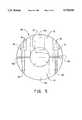
- FIG. 5is a top view of coupling unit of the mount, the unit being shown isolated from the other components of the cushioning conversion system except for a vertical member of the stud;
- FIG. 6is a detailed side view of the cushioning conversion machine.
- the system 10comprises a stand 12, a cushioning conversion machine 14, and a machine mounting assembly 16 which mounts the machine to the stand in such a manner that the machine 14 may be selectlvely rotated related to the stand 12 in a horizontal plane. (Compare FIGS. 3 and 4.)
- the stand 12includes an H-shaped base member 20 and a vertical member 22.
- the base member 20is made of square steel tubing and may include leveling feet, or pads, 24 for slight leveling adjustments of the stand 12 at the packaging site.
- the vertical member 22is made of steel, is circular in cross-section, and extends upward from an intermediate portion of the center leg of the "H" of the base member 20.
- the cushioning conversion machine 14converts sheet-like stock material into a dunnage product.
- the machine 14is positioned in a substantially horizontal orientation. In other words, an imaginary line from the machine's upstream end to its downstream end would be substantially horizontal.
- the machine mounting assembly 16includes a coupling unit 26, a rotating unit 28, and a platform unit 30.
- the coupling unit 26is non-rotatably, but vertically adjustably, coupled to the stand's vertical member 22, and thus the stand 12.
- the rotating unit 28is coupled to the coupling unit 26 for selective rotation in a horizontal plane relative to the coupling unit 26 (and therefore the vertical member 22 and the stand 12).
- the platform unit 30is fixedly coupled to the rotating unit 28 and, as explained in more detail below, provides a platform for the cushioning conversion machine 14.
- the machine 14is selectively rotatable in a horizontal plane, and also vertically adjustable, relative to the stand 12.
- the coupling unit 26is shown in more detail, and isolated from the other components of the system 10 except for the stand's vertical member 22.
- the coupling unit 26includes two semi-circular (in cross section) collars 32 and 34 which clamp together around the stand's vertical member 22. This clamping is accomplished by a pair of bolts 36 which extend through aligned bores 38 and 40 in the collars 32 and 34, respectively.
- the bores 38 in collar 32are wider at their radially outer portions to create a counterbore to accommodate the heads of the bolts 36.
- the bores 40 in the collar 34are threaded at their radially outer portions to accommodate the threaded tails of the bolts 36.
- the coupling unit 26further includes four stop slots 42 spaced at 90° increments along its outer circumference.
- Each of the collars 32 and 34includes a full central slot 42a and a pair of "half slots" 42b on each end. As is best shown in the drawing, the adjacent half slots 42b on the two collars join to form a full slot.
- the stop slots 42coordinate with the rotating unit 28 to secure the mount 16 (and thus the machine 14) at the desired rotational position, as is explained in more detail below.
- the rotating unit 28comprises tubular member 46 designed to rotate about the stand's vertical member 22.
- bearingswould preferably be used to accomplish this rotational coupling. More preferably, thrust bearings would be used in view of the sometimes substantial weight (300 to 400 pounds) of the machine 14 As is best seen in FIG. 2, the tubular member 46 rests upon the coupling unit 26 and thus is supported thereby on the stand's vertical member 22.
- the rotating unit 28further comprises a stop plate 48 fixedly mounted (such as by welding) to the lower end of the tubular member 46 which carries a spring plunger 50. As is best seen in FIG. 2, the spring plunger 50 is positioned for selective insertion into the stop slots 42 of the coupling unit 26 to lock the rotating unit 28 at a desired rotational orientation.
- the platform unit 30includes a pair of symmetrical mounting plates 54, a pair of side gussets 56, and a pair of shelf bars 58.
- the mounting plates 54are made of steel and are L-shaped in cross-section. The inner side of one leg of each of the plates 54 is welded to the tubular member 46. The distal ends of the other legs of the mounting plates 54 are attached (such as by welding) to the proximal end of the side gussets 56. (See FIGS. 3 and 4.)
- the side gussets 56are made of steel and are of a roughly triangular shape which tapers outwardly from their attachment with the mounting plates 54. (See FIG. 2.)
- One shelf bar 58is attached (such as by welding) to the upper edge of each of the side gussets 56. (See FIGS. 3 and 4.)
- the mounting plates 54 and the said gussets 56coordinate to support the shelf bars 58.
- the shelf bars 58are also made of steel and together form a "shelf" or “platform” upon which the cushioning conversion machine 14 rests. (See FIGS. 1 and 2.) Although not specifically shown in the drawings, coupling components may be provided to releasably mechanically couple the machine 14 to the shelf bars 58. In the illustrated and preferred embodiment, the machine 14 is positioned transversely relative to the shelf bars 58. In other words, an imaginary line from the machine's upstream end to its downstream end would be perpendicular to the shelf bars 58.
- the stand 12would be appropriately positioned relative to a packaging surface and the machine 14 rotated in a horizontal plane to the desired orientation.
- the packaging surfaceis a conveyor 60.
- the stand 12is positioned so that the side legs of the H-shaped base member 20 are positioned partially under the conveyor 60 and the center leg of the "H" is adjacent to, and parallel with, the conveyor 60.
- the machine mount 16is rotated to situate the machine 14 above and parallel to the conveyor 60. In other words, a line from the machine's upstream end to its downstream end would be parallel with the conveyor 60 and also the center leg of the stand's base member 20. In this manner, dunnage products produced by the machine 14 would be deposited on the conveyor 60.
- FIG. 4the machine 14 is shown rotated 90° counterclockwise relative to the stand 12 and the conveyor 60. This rotation is accomplished by removing the spring plunger 50 from the stop slot 42 on the coupling unit 26, rotating the rotating unit 28 (and thus the platform unit 30 and the machine 14) counterclockwise 90° and re-inserting the spring plunger 50 into the circumferentially adjacent stop slot 42.
- downstream portion of the machine 14When the machine 14 is rotated to the position shown in FIG. 4, the downstream portion of the machine 14 is no longer positioned above the conveyor 60 whereby, for instance, downstream components of the machine (such as the cutting assembly discussed below) may be more accessible for servicing.
- downstream components of the machinesuch as the cutting assembly discussed below
- the upstream portion on the machine 14would be positioned away from the conveyor 60 whereby, for instance, loading of the machine may be more convenient.
- the machine 14was rotated another 90° counterclockwise from the position shown in FIG. 4, the entire machine would be positioned away from the conveyor belt for overall servicing. In any event, after the servicing/loading tasks are completed, the machine 14 could be rotated back to its original position shown in FIG. 3
- the machine mount 16allows vertical adjustment of the machine 14 relative to the stand 12.
- the bolts 36 of the coupling unit 26would be loosened, the collars 32 and 34 move to the desired height and then the bolts 36 re-tightened.
- the machine 14 and/or the units 28 and 30would be desirably independently supported during this height adjustment process.
- the machine 14includes a frame 114 and a conversion assembly 116 mounted to the frame.
- the conversion assembly 116converts sheet-like stock material into a cushioning product.
- the machine 14converts multiple plies of recyclable and reusable Kraft paper into a continuous strip of dunnage two lateral pillow-like portions separated by a thin central band.
- the inventionmay be used in association with other forms of conversion assemblies. Consequently, the term "conversion assembly” is hereby defined as any assembly or any collection of assemblies (regardless of whether it is/they are structurally equivalent to the disclosed conversion assembly/assemblies) which converts a sheet-like stock material into a dunnage product.
- the conversion assembly 116includes a forming assembly 120 which is mounted to the frame 114.
- the forming assembly 120includes a converging chute and a triangular shaped former which extends partway into the chute through the wider upstream end thereof.
- the forming assembly 120causes inward rolling of the lateral sides of the sheet-like stock material to form a continuous strip having two lateral pillow-like portions and a central band therebetween. Details of such a assembly are set forth in U.S. Pat. No. 4,750,896, which has been incorporated by reference.
- the conversion assembly 116also includes a feed assembly 122 which is mounted to the frame 114, preferably downstream of the forming assembly 120.
- the feed assembly 122advances the stock material through the forming assembly 120.
- the feed assembly 122is a pulling/connecting assembly which includes a pair gears between which the stock material passes.
- the feed assembly 122performs a "pulling" function by drawing the continuous strip through the nip the two cooperating and opposed gears thereby pulling the stock material through the forming assembly 120.
- the feed assembly 122performs a "connecting" function when the two opposing gears connect, or more particularly coin, the central band of the continuous strip as it passes therethrough.
- the preferred gearsare disclosed in U.S. Pat. No. 4,968,291 which has been incorporated by reference.
- the cushioning conversion machine 14additionally includes a cutting assembly 124 which cuts the strip into sections of a desired length.
- the cutting assembly 124is positioned downstream of the forming assembly 120 and the feed assembly 122.
- the preferred cutting assembly 124is disclosed in detail in co-owned and co-pending U.S. application Ser. No. 08/188,305 to Simmons, entitled “Cushioning Conversion Machine Including a Cutting/Aligning Assembly", the entire disclosure of which is hereby incorporated by reference.
- the cutting assembly 124is mounted to the machine's frame 114 and may be viewed as part of the conversion assembly 116.
- the stock materialis supplied to the forming assembly 120 by a stock supply assembly 126 which is positioned upstream of the forming assembly 120.
- the illustrated sock supply assembly 126includes two lateral spaced brackets which are generally shaped like a sideways "U".
- the lower legs of the bracketsinclude slots which, when rolled stock material is used with the machine 14, cradle a supply rod extending through the core of the stock roll.
- the upper legs of the bracketscooperate to mount a sheet separator and constant-entry bar. Further details of a suitable stock supply assembly are set forth in co-owned U.S. Pat. No. 4,750,896, which has been incorporated by reference.
- the stock supply assembly 126is mounted to the machine's frame 114 and may be viewed as part of the conversion assembly 116.
- the illustrated cushioning conversion machine 14further includes a post-cutting constraining assembly 128 located downstream of the cutting assembly 124. During the conversion process, a cut section of dunnage will be urged or pushed downstream into the inlet of the assembly 128 by the approaching strip of dunnage.
- the post-cutting constraining assembly 128is mounted to the machine's frame 114 and may be viewed as part of the conversion assembly 116.
- the present inventionprovides a cushioning conversion system in which a machine may be selectively rotated relative to a stand in a horizontal plane.
Landscapes
- Making Paper Articles (AREA)
Abstract
Description
Claims (17)
Priority Applications (3)
| Application Number | Priority Date | Filing Date | Title |
|---|---|---|---|
| US08/482,826US5730696A (en) | 1995-06-07 | 1995-06-07 | Cushioning conversion machine selectively pivotable in a horizontal plane |
| PCT/US1996/009169WO1996040494A1 (en) | 1995-06-07 | 1996-06-04 | Cushioning conversion system having horizontally pivotable mounting relative to a stand |
| AU60922/96AAU6092296A (en) | 1995-06-07 | 1996-06-04 | Cushioning conversion system having horizontally pivotable m ounting relative to a stand |
Applications Claiming Priority (1)
| Application Number | Priority Date | Filing Date | Title |
|---|---|---|---|
| US08/482,826US5730696A (en) | 1995-06-07 | 1995-06-07 | Cushioning conversion machine selectively pivotable in a horizontal plane |
Publications (1)
| Publication Number | Publication Date |
|---|---|
| US5730696Atrue US5730696A (en) | 1998-03-24 |
Family
ID=23917615
Family Applications (1)
| Application Number | Title | Priority Date | Filing Date |
|---|---|---|---|
| US08/482,826Expired - Fee RelatedUS5730696A (en) | 1995-06-07 | 1995-06-07 | Cushioning conversion machine selectively pivotable in a horizontal plane |
Country Status (3)
| Country | Link |
|---|---|
| US (1) | US5730696A (en) |
| AU (1) | AU6092296A (en) |
| WO (1) | WO1996040494A1 (en) |
Cited By (15)
| Publication number | Priority date | Publication date | Assignee | Title |
|---|---|---|---|---|
| US6179765B1 (en) | 1998-10-30 | 2001-01-30 | Ft Acquisition, L.P. | Paper dispensing system and method |
| WO2001096097A3 (en)* | 2000-06-13 | 2002-05-02 | Ranpak Corp | Dunnage conversion system and method with stock roll loader |
| WO2002078941A1 (en)* | 2001-03-29 | 2002-10-10 | Zsolt Toth | Compact apparatus and system for creating and dispensing cushioning dunnage |
| US20030073558A1 (en)* | 2001-10-15 | 2003-04-17 | Bill Chesterson | Machine and method for converting paper stock into dunnage |
| US20030087741A1 (en)* | 2001-03-29 | 2003-05-08 | Zsolt Toth | Method, apparatus and system for making cushioning product, and roll tensioner therefor |
| US6673001B2 (en) | 2001-03-29 | 2004-01-06 | Zsolt Toth | Compact apparatus and system for creating and dispensing cushioning dunnage |
| US20040266598A1 (en)* | 2001-03-29 | 2004-12-30 | Zsolt Toth | Cushioning conversion system and method |
| US6910997B1 (en)* | 2004-03-26 | 2005-06-28 | Free-Flow Packaging International, Inc. | Machine and method for making paper dunnage |
| US20070117703A1 (en)* | 2005-11-22 | 2007-05-24 | Sealed Air Corporation | Machine and method for converting a web of material into dunnage |
| US20070123406A1 (en)* | 2003-07-07 | 2007-05-31 | Ranpak Corp. | Cutterless dunnage converter and method |
| US20090258775A1 (en)* | 2008-04-11 | 2009-10-15 | Chan Simon C S | Apparatus, systems and methods for producing cushioning material |
| US20110230325A1 (en)* | 2002-04-22 | 2011-09-22 | Ranpak Corp. | Dunnage converter system |
| US20120015793A1 (en)* | 2009-05-04 | 2012-01-19 | Ranpak Corp. | Drop and slide mechanism for use with dunnage conversion machine and method |
| US11590724B2 (en) | 2018-08-31 | 2023-02-28 | Bluegrass Business Products, Inc. | Paper crumpling machine |
| US11780203B2 (en) | 2019-09-03 | 2023-10-10 | Bluegrass Business Products, Inc. | Paper crumpling machine |
Citations (9)
| Publication number | Priority date | Publication date | Assignee | Title |
|---|---|---|---|---|
| US2469904A (en)* | 1947-01-10 | 1949-05-10 | Edward A Szuba | Gauge support |
| US3162922A (en)* | 1961-07-07 | 1964-12-29 | Alziari Louis | Tubular metal stay for molds |
| US3212748A (en)* | 1963-07-05 | 1965-10-19 | Faurot George Wesley | Combination desk and cabinet rack structure |
| US3391889A (en)* | 1966-06-07 | 1968-07-09 | Cocker Machine & Foundry Compa | Yarn package holder for textile creels |
| US4226390A (en)* | 1977-11-07 | 1980-10-07 | Medishield Corporation Limited | Mounting device |
| US5123889A (en)* | 1990-10-05 | 1992-06-23 | Ranpak Corporation | Downsized cushioning dunnage conversion machine and cutting assemblies for use on such a machine |
| US5255627A (en)* | 1992-05-22 | 1993-10-26 | Williams Herbert T | Flag and flagpole attachment |
| US5322477A (en)* | 1990-10-05 | 1994-06-21 | Ranpak Corp. | Downsized cushioning dunnage conversion machine and packaging systems employing the same |
| US5487717A (en)* | 1993-05-21 | 1996-01-30 | Ranpak Corp. | Dispensing table for a cushioning conversion machine |
- 1995
- 1995-06-07USUS08/482,826patent/US5730696A/ennot_activeExpired - Fee Related
- 1996
- 1996-06-04WOPCT/US1996/009169patent/WO1996040494A1/enactiveApplication Filing
- 1996-06-04AUAU60922/96Apatent/AU6092296A/ennot_activeAbandoned
Patent Citations (10)
| Publication number | Priority date | Publication date | Assignee | Title |
|---|---|---|---|---|
| US2469904A (en)* | 1947-01-10 | 1949-05-10 | Edward A Szuba | Gauge support |
| US3162922A (en)* | 1961-07-07 | 1964-12-29 | Alziari Louis | Tubular metal stay for molds |
| US3212748A (en)* | 1963-07-05 | 1965-10-19 | Faurot George Wesley | Combination desk and cabinet rack structure |
| US3391889A (en)* | 1966-06-07 | 1968-07-09 | Cocker Machine & Foundry Compa | Yarn package holder for textile creels |
| US4226390A (en)* | 1977-11-07 | 1980-10-07 | Medishield Corporation Limited | Mounting device |
| US5123889A (en)* | 1990-10-05 | 1992-06-23 | Ranpak Corporation | Downsized cushioning dunnage conversion machine and cutting assemblies for use on such a machine |
| US5322477A (en)* | 1990-10-05 | 1994-06-21 | Ranpak Corp. | Downsized cushioning dunnage conversion machine and packaging systems employing the same |
| US5468208A (en)* | 1990-10-05 | 1995-11-21 | Ranpak Corp. | Downsized cushioning dunnage conversion machine and packaging systems employing the same |
| US5255627A (en)* | 1992-05-22 | 1993-10-26 | Williams Herbert T | Flag and flagpole attachment |
| US5487717A (en)* | 1993-05-21 | 1996-01-30 | Ranpak Corp. | Dispensing table for a cushioning conversion machine |
Cited By (37)
| Publication number | Priority date | Publication date | Assignee | Title |
|---|---|---|---|---|
| US6179765B1 (en) | 1998-10-30 | 2001-01-30 | Ft Acquisition, L.P. | Paper dispensing system and method |
| WO2001096097A3 (en)* | 2000-06-13 | 2002-05-02 | Ranpak Corp | Dunnage conversion system and method with stock roll loader |
| US20070117704A1 (en)* | 2001-03-29 | 2007-05-24 | Zsolt Toth | Compact apparatus and system for creating and dispensing cushioning dunnage |
| US7172548B2 (en) | 2001-03-29 | 2007-02-06 | Zsolt Design Engineering, Inc. | Cushioning conversion system and method |
| US7479100B2 (en) | 2001-03-29 | 2009-01-20 | Zsolt Design Engineering, Inc. | Cushioning conversion system and method |
| US20030087741A1 (en)* | 2001-03-29 | 2003-05-08 | Zsolt Toth | Method, apparatus and system for making cushioning product, and roll tensioner therefor |
| US6673001B2 (en) | 2001-03-29 | 2004-01-06 | Zsolt Toth | Compact apparatus and system for creating and dispensing cushioning dunnage |
| US7347809B2 (en) | 2001-03-29 | 2008-03-25 | Zsolt Design Engineering, Inc. | Compact apparatus and system for creating and dispensing cushioning dunnage |
| US20040043883A1 (en)* | 2001-03-29 | 2004-03-04 | Zsolt Toth | Compact apparatus and system for creating and dispensing cushioning dunnage |
| US20040266598A1 (en)* | 2001-03-29 | 2004-12-30 | Zsolt Toth | Cushioning conversion system and method |
| US7335151B2 (en) | 2001-03-29 | 2008-02-26 | Zsolt Design Engineering, Inc. | Method, apparatus and system for making cushioning product, and roll tensioner therefor |
| WO2002078941A1 (en)* | 2001-03-29 | 2002-10-10 | Zsolt Toth | Compact apparatus and system for creating and dispensing cushioning dunnage |
| US7022060B2 (en)* | 2001-03-29 | 2006-04-04 | Zsolt Design Engineering, Inc. | Method, apparatus and system for making cushioning product, and roll tensioner therefor |
| US20060135336A1 (en)* | 2001-03-29 | 2006-06-22 | Zsolt Toth | Method, apparatus and system for making cushioning product, and roll tensioner therefor |
| US7163503B2 (en) | 2001-03-29 | 2007-01-16 | Zsolt Design Engineering, Inc. | Compact apparatus and system for creating and dispensing cushioning dunnage |
| AU2002244237B2 (en)* | 2001-03-29 | 2007-08-02 | Zsolt Toth | Compact apparatus and system for creating and dispensing cushioning dunnage |
| US6503182B2 (en)* | 2001-03-29 | 2003-01-07 | Zsolt Design Engineering, Inc. | Compact apparatus and system for creating and dispensing cushioning dunnage |
| US20070117705A1 (en)* | 2001-03-29 | 2007-05-24 | Zsolt Toth | Cushioning conversion system and method |
| US20030073558A1 (en)* | 2001-10-15 | 2003-04-17 | Bill Chesterson | Machine and method for converting paper stock into dunnage |
| US20110230325A1 (en)* | 2002-04-22 | 2011-09-22 | Ranpak Corp. | Dunnage converter system |
| WO2004012930A1 (en)* | 2002-08-01 | 2004-02-12 | Zsolt Toth | Compact apparatus and system for creating and dispensing cushioning dunnage |
| EP2799223A2 (en) | 2003-07-07 | 2014-11-05 | Ranpak Corp. | Cutterless dunnage converter and method |
| US20070123406A1 (en)* | 2003-07-07 | 2007-05-31 | Ranpak Corp. | Cutterless dunnage converter and method |
| US9370914B2 (en) | 2003-07-07 | 2016-06-21 | Ranpak Corp. | Cutterless dunnage converter and method |
| US20080076654A1 (en)* | 2003-07-07 | 2008-03-27 | Ranpak Corp. | Cutterless dunnage converter and method |
| US7407471B2 (en)* | 2003-07-07 | 2008-08-05 | Ranpak Corp. | Cutterless dunnage converter and method |
| EP2669080A1 (en) | 2003-07-07 | 2013-12-04 | Ranpak Corp. | Dunnage converter and stand |
| US20050215408A1 (en)* | 2004-03-26 | 2005-09-29 | Vladimir Yampolsky | Method For Making Paper Dunnage |
| US7651455B2 (en) | 2004-03-26 | 2010-01-26 | Free Flow Packaging International, Inc. | Method for making paper dunnage |
| US6910997B1 (en)* | 2004-03-26 | 2005-06-28 | Free-Flow Packaging International, Inc. | Machine and method for making paper dunnage |
| US20070117703A1 (en)* | 2005-11-22 | 2007-05-24 | Sealed Air Corporation | Machine and method for converting a web of material into dunnage |
| US8550971B2 (en) | 2008-04-11 | 2013-10-08 | Nuevopak Technology Company Limited | Systems for producing cushioning material |
| US20090258775A1 (en)* | 2008-04-11 | 2009-10-15 | Chan Simon C S | Apparatus, systems and methods for producing cushioning material |
| US20120015793A1 (en)* | 2009-05-04 | 2012-01-19 | Ranpak Corp. | Drop and slide mechanism for use with dunnage conversion machine and method |
| US8944982B2 (en)* | 2009-05-04 | 2015-02-03 | Ranpak Corp. | Drop and slide mechanism for use with dunnage conversion machine and method |
| US11590724B2 (en) | 2018-08-31 | 2023-02-28 | Bluegrass Business Products, Inc. | Paper crumpling machine |
| US11780203B2 (en) | 2019-09-03 | 2023-10-10 | Bluegrass Business Products, Inc. | Paper crumpling machine |
Also Published As
| Publication number | Publication date |
|---|---|
| WO1996040494A1 (en) | 1996-12-19 |
| AU6092296A (en) | 1996-12-30 |
Similar Documents
| Publication | Publication Date | Title |
|---|---|---|
| US5730696A (en) | Cushioning conversion machine selectively pivotable in a horizontal plane | |
| US5902223A (en) | Cushoning conversion machine | |
| AU685970B2 (en) | Downsized cushioning dunnage conversion machine and packaging system employing the same | |
| US5791483A (en) | Cushioning product | |
| US5468208A (en) | Downsized cushioning dunnage conversion machine and packaging systems employing the same | |
| EP0730525B1 (en) | Dispensing table for a cushioning conversion machine | |
| HK1007988B (en) | Cushioning dunnage conversion machine and method of producing cut sections of cushioning dunnage product | |
| US20040043883A1 (en) | Compact apparatus and system for creating and dispensing cushioning dunnage | |
| EP2052850B1 (en) | Cushioning conversion machine and method | |
| US6402674B1 (en) | Cushioning conversion system and method with dancer roller cart | |
| US5658229A (en) | Downsized cushioning dumnage conversion machine and cutting assemblies for use on such a machine | |
| US20030040416A1 (en) | Cushioning conversion machine and method with plural constant entry rollers and moving blade shutter | |
| US6210310B1 (en) | Cushioning conversion machine and method with enhanced stock separation and forming | |
| EP0888878B1 (en) | Cushioning conversion machine and packaging system including such a machine | |
| US5891010A (en) | Cushioning conversion machine with swing-mounted stock roll support and method | |
| US6090033A (en) | Cushioning conversion machine for producing U-shape pads | |
| GB2332192A (en) | Cushioning conversion machine with integral shelf | |
| EP1310355A2 (en) | Cushioning conversion machine and method |
Legal Events
| Date | Code | Title | Description |
|---|---|---|---|
| AS | Assignment | Owner name:RANPAK CORP., OHIO Free format text:ASSIGNMENT OF ASSIGNORS INTEREST;ASSIGNOR:SIMMONS, JAMES A.;REEL/FRAME:007552/0371 Effective date:19950607 | |
| AS | Assignment | Owner name:KEYBANK NATIONAL ASSOCIATION, OHIO Free format text:SECURITY AGREEMENT;ASSIGNOR:RANPAK CORP.;REEL/FRAME:008328/0726 Effective date:19960820 | |
| FEPP | Fee payment procedure | Free format text:PAYOR NUMBER ASSIGNED (ORIGINAL EVENT CODE: ASPN); ENTITY STATUS OF PATENT OWNER: SMALL ENTITY | |
| FPAY | Fee payment | Year of fee payment:4 | |
| AS | Assignment | Owner name:GENERAL ELECTRIC CAPITAL CORPORATION, AS AGENT, CO Free format text:SECURITY AGREEMENT;ASSIGNOR:RANPAK CORP.;REEL/FRAME:012418/0493 Effective date:20011228 | |
| AS | Assignment | Owner name:GENERAL ELECTRIC CAPITAL CORPORATION, CONNECTICUT Free format text:SECURITY AGREEMENT;ASSIGNOR:RANPAK CORP.;REEL/FRAME:014709/0832 Effective date:20040526 | |
| AS | Assignment | Owner name:SPECIAL SITUATIONS INVESTING GROUP, INC., NEW YORK Free format text:SECURITY AGREEMENT;ASSIGNOR:RANPAK CORP.;REEL/FRAME:015676/0883 Effective date:20040727 | |
| AS | Assignment | Owner name:GENERAL ELECTRIC CAPITAL CORPORATION, AS AGENT, CO Free format text:SECURITY INTEREST;ASSIGNOR:RANPAK CORP;REEL/FRAME:015861/0341 Effective date:20050317 | |
| REMI | Maintenance fee reminder mailed | ||
| AS | Assignment | Owner name:RANPAK CORP, OHIO Free format text:RELEASE OF SECURITY INTEREST;ASSIGNOR:SPECIAL SITUATIONS INVESTING GROUP, INC.;REEL/FRAME:016784/0231 Effective date:20041104 | |
| AS | Assignment | Owner name:GENERAL ELECTRIC CAPITAL CORPROATION, CONNECTICUT Free format text:SECURITY AGREEMENT;ASSIGNOR:RANPAK CORP.;REEL/FRAME:016945/0612 Effective date:20051214 | |
| AS | Assignment | Owner name:RANPAK CORP., OHIO Free format text:RELEASE OF SECURITY INTEREST;ASSIGNOR:GENERAL ELECTRIC CAPITAL CORPORATION;REEL/FRAME:016967/0696 Effective date:20051214 Owner name:RANPAK CORP., OHIO Free format text:RELEASE OF SECURITY INTEREST;ASSIGNOR:GENERAL ELECTRIC CAPITAL CORPORATION;REEL/FRAME:016976/0302 Effective date:20051214 Owner name:RANPAK CORP., OHIO Free format text:RELEASE OF SECURITY INTEREST;ASSIGNOR:GENERAL ELECTRIC CAPITAL CORPORATION;REEL/FRAME:016976/0285 Effective date:20051214 | |
| LAPS | Lapse for failure to pay maintenance fees | ||
| STCH | Information on status: patent discontinuation | Free format text:PATENT EXPIRED DUE TO NONPAYMENT OF MAINTENANCE FEES UNDER 37 CFR 1.362 | |
| FP | Lapsed due to failure to pay maintenance fee | Effective date:20060324 | |
| AS | Assignment | Owner name:RANPAK CORP., OHIO Free format text:RELEASE OF SECURITY INTEREST INTELLECTUAL PROPERTY COLLATERAL;ASSIGNOR:GENERAL ELECTRIC CAPITAL CORPORATION, AS AGENT;REEL/FRAME:020362/0864 Effective date:20071227 Owner name:RANPAK CORP.,OHIO Free format text:RELEASE OF SECURITY INTEREST INTELLECTUAL PROPERTY COLLATERAL;ASSIGNOR:GENERAL ELECTRIC CAPITAL CORPORATION, AS AGENT;REEL/FRAME:020362/0864 Effective date:20071227 | |
| AS | Assignment | Owner name:AMERICAN CAPITAL FINANCIAL SERVICES, INC., AS AGEN Free format text:FIRST LIEN PATENT SECURITY AGREEMENT;ASSIGNOR:RANPAK CORP.;REEL/FRAME:020690/0276 Effective date:20071227 | |
| AS | Assignment | Owner name:AMERICAN CAPITAL FINANCIAL SERVICES, INC., AS AGEN Free format text:SECOND LIEN PATENT SECURITY AGREEMENT;ASSIGNOR:RANPAK CORP.;REEL/FRAME:020497/0927 Effective date:20071227 |