US5730657A - Shaft coupling - Google Patents
Shaft couplingDownload PDFInfo
- Publication number
- US5730657A US5730657AUS08/821,607US82160797AUS5730657AUS 5730657 AUS5730657 AUS 5730657AUS 82160797 AUS82160797 AUS 82160797AUS 5730657 AUS5730657 AUS 5730657A
- Authority
- US
- United States
- Prior art keywords
- shaft
- tubular sleeve
- gear
- cylindrical bushing
- shaft coupling
- Prior art date
- Legal status (The legal status is an assumption and is not a legal conclusion. Google has not performed a legal analysis and makes no representation as to the accuracy of the status listed.)
- Expired - Fee Related
Links
Images


Classifications
- F—MECHANICAL ENGINEERING; LIGHTING; HEATING; WEAPONS; BLASTING
- F16—ENGINEERING ELEMENTS AND UNITS; GENERAL MEASURES FOR PRODUCING AND MAINTAINING EFFECTIVE FUNCTIONING OF MACHINES OR INSTALLATIONS; THERMAL INSULATION IN GENERAL
- F16D—COUPLINGS FOR TRANSMITTING ROTATION; CLUTCHES; BRAKES
- F16D3/00—Yielding couplings, i.e. with means permitting movement between the connected parts during the drive
- F16D3/16—Universal joints in which flexibility is produced by means of pivots or sliding or rolling connecting parts
- F16D3/18—Universal joints in which flexibility is produced by means of pivots or sliding or rolling connecting parts the coupling parts (1) having slidably-interengaging teeth
- Y—GENERAL TAGGING OF NEW TECHNOLOGICAL DEVELOPMENTS; GENERAL TAGGING OF CROSS-SECTIONAL TECHNOLOGIES SPANNING OVER SEVERAL SECTIONS OF THE IPC; TECHNICAL SUBJECTS COVERED BY FORMER USPC CROSS-REFERENCE ART COLLECTIONS [XRACs] AND DIGESTS
- Y10—TECHNICAL SUBJECTS COVERED BY FORMER USPC
- Y10S—TECHNICAL SUBJECTS COVERED BY FORMER USPC CROSS-REFERENCE ART COLLECTIONS [XRACs] AND DIGESTS
- Y10S464/00—Rotary shafts, gudgeons, housings, and flexible couplings for rotary shafts
- Y10S464/901—Rapid attachment or release
Definitions
- This inventionrelates to articulating shaft couplings.
- U.S. Pat. No. 1,429,980describes an articulating shaft coupling including a pair of gears on facing ends of a first shaft and a second shaft for transfer of torque throughout a range of articulation angles between the first and the second shafts and a retainer operative to prevent separation of the gears.
- the retainerconsists of a pair of arc-shaped shells clamped together to form a cage around the meshing gears and an annular flange on the retainer seated in an annular groove in one of the shafts for linear retention of the cage.
- An articulating shaft coupling according to this inventionis an improvement relative to the articulating shaft coupling described in the aforesaid U.S. Pat. No. 1,429,980.
- This inventionis a new and improved articulating shaft coupling including a first gear on an end of a first shaft, a second gear on an end of a second shaft meshing with the first gear, a tubular sleeve around the meshing first and second gears, a universal thrust bearing between the tubular sleeve and the first shaft, and a self-locking linear retainer between the tubular sleeve and the second shaft.
- the self-locking linear retainerincludes a cylindrical bushing attached to the second shaft for linear translation as a unit therewith having a diameter calculated for close fit in the tubular sleeve, a plurality of windows in the tubular sleeve, and a plurality of resilient barbs on the cylindrical bushing which are flexed inward when the end of the second shaft having the second gear thereon is plugged into the tubular sleeve and which resiliently expand into the windows to prevent dislodgment of the second shaft from the tubular sleeve.
- the cylindrical bushinghas lugs which extend inward into a groove in the second shaft and is longitudinally split for radial expansion during installation of the lugs into the groove.
- the universal thrust bearingincludes a spherical shoulder on the first shaft, a bearing ring seated on the spherical shoulder, an annular washer seated on a plurality of dimples on the tubular sleeve, and a spring compressed between the bearing ring and the washer which concurrently thrusts together the bearing ring and the spherical shoulder and the first and the second gears.
- FIG. 1is a perspective view of an articulating shaft coupling according to this invention
- FIG. 2is an enlarged sectional view taken generally along the plane indicated by lines 2--2 in FIG. 1;
- FIG. 3is a sectional view taken generally along the plane indicated by lines 3--3 in FIG. 2;
- FIG. 4is similar to FIG. 3 but showing elements of the articulating shaft coupling according to this invention in different relative positions;
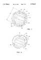
- FIG. 5is an exploded perspective view of the articulating shaft coupling according to this invention.
- FIG. 6is a view taken generally along the plane indicated by lines 6--6 in FIG. 5;
- FIG. 7is a view taken generally along the plane indicated by lines 7--7 in FIG. 5;
- FIG. 8is a longitudinal sectional view of the articulating shaft coupling according to this invention in a motor vehicle steering shaft application.
- an articulating shaft coupling 10couples together for unitary rotation and for relative articulation a first shaft 12 and a second shaft 14.
- a spherical end 16 on an enlarged head 18 of the first shaft 12faces a flat end 20 on the second shaft.
- a first gear 22 of the shaft coupling 10consists of a plurality of wedge-shaped spur gear teeth 24 on the enlarged head 18 separated by a corresponding plurality of wedge-shaped troughs 26 open through the spherical end 16 of the first shaft.
- the gear teeth 24 and troughs 26converge toward a concave socket 28 in the middle of spherical end 16 of the first shaft.
- a second gear 30 of the shaft coupling 10consists of a plurality of wedge-shaped spur gear teeth 32 on the flat end 20 separated by a corresponding plurality of wedge-shaped troughs 34 open through the flat end 20.
- the gear teeth 32 and troughs 34converge toward a convex pilot 36 in the middle of flat end 20 of the second shaft.
- Mesh between the first and the second gears 22, 30is characterized by the gear teeth 24 of the first gear seated in a respective ones of the troughs 34 between the gear teeth 32 of the second gear and vice versa with the convex pilot 36 seated in the concave socket 28.
- the gear teeth 24, 32cooperate in transferring torque between the first and the second shafts 12, 14 at the same time that clearance between the spherical end 16 of the first shaft and the flat end 20 of the second shaft accommodates universal articulation, i.e., articulation in any direction, of the first shaft relative to the second shaft about the coincident geometric centers of the convex socket 28 and the concave pilot 36.
- a tubular sleeve 38 of the shaft coupling 10having a first end 40 and a second end 42 is disposed around the first and the second shafts 12, 14 and overlaps the first and the second gears 22, 30 in the direction of a longitudinal centerline 44 of the shaft coupling.
- An inside diameter dimension D 1 of the tubular sleeve 38exceeds the diameters of the first shaft 12 and the second shaft 14 and the enlarged head 18 on the first shaft for unrestricted linear translation relative to the first and the second shafts in the direction of the centerline 44.
- a universal thrust bearing 46 of the shaft coupling 10includes a plurality of dimples 48 in the tubular sleeve 38 near the second end 42 thereof, an annular washer 50 in the tubular sleeve seated on the dimples, a plastic bearing ring 52, and a wave spring 54 compressed between the bearing ring and the annular washer.
- the universal thrust bearing 46further includes a spherical shoulder 56 on the enlarged head 18 of the first shaft, the geometric center of which coincides with the geometric center of the spherical socket 28, and a spherical seat 58 on the bearing ring 52 facing the spherical shoulder.
- a self-locking linear retainer 60 of the shaft coupling 10includes a cylindrical bushing 62 and a plurality of windows 64 in the tubular sleeve 38.
- the cylindrical bushing 62has an outside diameter dimension D 2 , FIG. 3, corresponding substantially to inside diameter dimension D 1 of the tubular sleeve, i.e., calculated to achieve a close fit in the tubular sleeve 38, a plurality of integral, radially inward projecting lugs 66, and a plurality of integral, radially outward projecting resilient barbs 68.
- Each of the lugs 66seats in an annular groove 70 in the second shaft 14 with a pair of side edges 72A, 72B of the lug facing a corresponding pair of side edges 74A, 74B of the annular groove whereby the cylindrical bushing is attached to the second shaft for unitary linear translation therewith in the direction of the centerline 44.
- Each of the barbs 68is aligned with a respective one of the windows 64 in the tubular sleeve 38 with a distal end 76 of each barb bearing against an adjacent edge 78 of the window to prevent dislodgment of the cylindrical bushing 62 and the second shaft 14 from the first end 40 of the tubular sleeve.
- a linear span dimension D 3 of the tubular sleeve 38 between the dimples 48 and the edges 78 of the windows 64is calculated to effect linear compression of the wave spring 54 when the first and the second gears 22, 30 are in mesh.
- the thrust of the wave springis conducted to the first shaft 12 through the bearing ring 52 and to the second shaft 14 through the tubular sleeve 38 and the cylindrical bushing 62 whereby the first and the second gears are resiliently thrust together in the direction of the centerline 44.
- the spherical seat 58 of the bearing ring 52is thrust against the spherical shoulder 56 on the first shaft 12 and cooperates therewith in accommodating universal articulation of the first shaft relative to the tubular sleeve 38 about the geometric center of the spherical shoulder 56 through an angle of about ⁇ 5°.
- the cylindrical bushing 62maintains linear alignment between the tubular sleeve and the second shaft 14.
- the shaft coupling 10is assembled by inserting the annular washer 50, the wave spring 54, and the bearing ring 52 in the tubular sleeve 38 and sliding the sleeve linearly on the first shaft 12 from behind the enlarged head 18 on the latter until the bearing ring seats on the spherical shoulder 56.
- the cylindrical bushing 62has a longitudinal split 80 therein which permits the bushing to be resiliently expanded, FIG. 4, to a diameter sufficient for passage of the lugs 66 over the outside of the second shaft 14 until the lugs achieve registry with and snap into the annular groove 70 in the second shaft.
- the shaft coupling 10is illustrated coupling together for unitary rotation and relative universal articulation a first shaft segment 82 and a second shaft segment 84 of a motor vehicle steering shaft 86 corresponding, respectively, to the first and the second shahs 12, 14 described above.
- the second shaft segment 84is connected to a third shaft segment 88 of the steering shaft 86 through a torsion bar 90.
- a manual steering wheel, not shown, of the motor vehicleis connected to the first shaft segment for rotation as a unit therewith.
- the third shaft segmentis connected to dirigible wheels, not shown, of the motor vehicle through a conventional steering gear.
- An electric power assist apparatus 92 of the motor vehicleincludes a housing 94 on which the second and third shaft segments 84, 88 are rotatably supported by a pair of ball bearings 96A, 96B and a sleeve bearing 98.
- a worm wheel 100is rigidly attached to the third shaft segment 88 in an internal chamber 102 of the housing 94 and meshes with a worm gear 104 connected to an output shaft, not shown, of an electric motor on the speed reducer housing.
- a transducer 106 in the internal chamber 102 of the speed reducer housingoverlaps the second and the third shaft segments 84, 88 and produces an electronic signal corresponding to the angle of relative rotation between the second and the third shaft segments.
- An electronic controlturns the aforesaid electric motor on and off in accordance with signals from the transducer 106.
- Output torque of the electric motoris applied to the steering shaft 86 through the worm gear 104 and the worm wheel 100 to supplement manual effort applied at the aforesaid manual steering wheel.
- the bearings 96A, 96B, 98 on the speed reducer housing 94are relatively high precision bearings to minimize transducer signal error attributable to lateral runout of the shaft segments 84, 88.
- a bearing, not shown, between a steering column and the first shaft segment 82 remote from the speed reducer housing 94has more manufacturing tolerance for easier assembly of the steering shaft on a steering column.
- the shaft coupling 10accommodates low angle articulation between the first and the second shaft segments 82, 84 attributable to manufacturing tolerance differences between the bearing supporting the first shaft segment 82 and the bearings supporting the second and the third shaft segments 84, 88.
- the automatic retention of the second shaft segment 84 in the tubular sleeve of the shaft coupling 10is accomplished at rates consistent with high volume motor vehicle manufacturing practices.
Landscapes
- Engineering & Computer Science (AREA)
- General Engineering & Computer Science (AREA)
- Mechanical Engineering (AREA)
- Steering Controls (AREA)
- Support Of The Bearing (AREA)
- Catching Or Destruction (AREA)
Abstract
Description
Claims (4)
Priority Applications (4)
| Application Number | Priority Date | Filing Date | Title |
|---|---|---|---|
| US08/821,607US5730657A (en) | 1997-03-20 | 1997-03-20 | Shaft coupling |
| IT98RM000168AIT1299384B1 (en) | 1997-03-20 | 1998-03-16 | JOINT FOR TREES |
| DE19811904ADE19811904A1 (en) | 1997-03-20 | 1998-03-18 | Shaft coupling |
| JP10068015AJP2933592B2 (en) | 1997-03-20 | 1998-03-18 | Shaft coupling |
Applications Claiming Priority (1)
| Application Number | Priority Date | Filing Date | Title |
|---|---|---|---|
| US08/821,607US5730657A (en) | 1997-03-20 | 1997-03-20 | Shaft coupling |
Publications (1)
| Publication Number | Publication Date |
|---|---|
| US5730657Atrue US5730657A (en) | 1998-03-24 |
Family
ID=25233822
Family Applications (1)
| Application Number | Title | Priority Date | Filing Date |
|---|---|---|---|
| US08/821,607Expired - Fee RelatedUS5730657A (en) | 1997-03-20 | 1997-03-20 | Shaft coupling |
Country Status (4)
| Country | Link |
|---|---|
| US (1) | US5730657A (en) |
| JP (1) | JP2933592B2 (en) |
| DE (1) | DE19811904A1 (en) |
| IT (1) | IT1299384B1 (en) |
Cited By (14)
| Publication number | Priority date | Publication date | Assignee | Title |
|---|---|---|---|---|
| US5878832A (en)* | 1997-08-13 | 1999-03-09 | General Motors Corporation | Steering apparatus for motor vehicle |
| US5980389A (en)* | 1996-10-04 | 1999-11-09 | Gkn Walterscheid Gmbh | Driveshaft with coupling means |
| US6065898A (en)* | 1995-08-07 | 2000-05-23 | The Regents Of The University Of California | Three tooth kinematic coupling |
| US6386747B1 (en)* | 2000-01-18 | 2002-05-14 | Shu-Hung Liao | Apparatus for mixing cement |
| US6450783B1 (en)* | 1999-11-19 | 2002-09-17 | Honda Giken Kogyo Kabushiki Kaisha | Engine with oil pump |
| US6672966B2 (en) | 2001-07-13 | 2004-01-06 | Honeywell International Inc. | Curvic coupling fatigue life enhancement through unique compound root fillet design |
| US20050070365A1 (en)* | 2003-09-30 | 2005-03-31 | Riefe Richard K. | Bushing for telescoping steering column assembly |
| US20090093317A1 (en)* | 2007-10-05 | 2009-04-09 | Enplas Corporation | Rotary shaft coupling |
| US20090299276A1 (en)* | 2004-02-26 | 2009-12-03 | Dexcom, Inc. | Integrated delivery device for continuous glucose sensor |
| US20110158744A1 (en)* | 2009-12-29 | 2011-06-30 | Dornfeld Michael S | Face coupling |
| US8292150B2 (en) | 2010-11-02 | 2012-10-23 | Tyco Healthcare Group Lp | Adapter for powered surgical devices |
| US20130163712A1 (en)* | 2010-07-06 | 2013-06-27 | Areva Np | Bwr nuclear fuel assembly with snap-in sleeve spring |
| US10449682B2 (en) | 2015-12-22 | 2019-10-22 | Koninklijke Philips N.V. | Coupling mechanism for a drive train of a hair cutting appliance |
| US11499611B2 (en)* | 2019-07-12 | 2022-11-15 | R.H. Sheppard Co., Inc. | Coupled steering gear shaft |
Families Citing this family (2)
| Publication number | Priority date | Publication date | Assignee | Title |
|---|---|---|---|---|
| DE102007053728B4 (en)* | 2007-11-10 | 2011-12-22 | Schaeffler Technologies Gmbh & Co. Kg | Hub unit for transmitting torque and a drive unit with the hub unit |
| US20120025054A1 (en)* | 2009-03-31 | 2012-02-02 | Musha Kazuhiro | Holding apparatus, conveying apparatus, and rotation-transmitting apparatus |
Citations (26)
| Publication number | Priority date | Publication date | Assignee | Title |
|---|---|---|---|---|
| US1040417A (en)* | 1912-05-22 | 1912-10-08 | Bert O Rhodes | Universal joint. |
| US1196268A (en)* | 1915-10-25 | 1916-08-29 | Eli Noel | Universal joint. |
| US1298680A (en)* | 1918-02-16 | 1919-04-01 | John R Dunham | Flexible coupling. |
| US1429980A (en)* | 1921-12-16 | 1922-09-26 | Charles M Spangler | Universal joint for coupling shafts |
| US1656715A (en)* | 1926-09-30 | 1928-01-17 | Pneumatic Appliances Corp | Universal joint |
| US1791763A (en)* | 1929-05-02 | 1931-02-10 | Al Metal Universal Joint Compa | Flexible coupling |
| US2098317A (en)* | 1935-09-19 | 1937-11-09 | Staunt Martin | Dental appliance |
| US2381102A (en)* | 1943-10-12 | 1945-08-07 | Douglas Aircraft Co Inc | Flexible adapter |
| US2578763A (en)* | 1946-03-11 | 1951-12-18 | Trbojevich Nikola | Constant velocity universal joint |
| US2640335A (en)* | 1949-08-16 | 1953-06-02 | Wingquist Sven Gustaf | Universal joint |
| US4055185A (en)* | 1976-03-02 | 1977-10-25 | American Sterilizer Company | Rotary drill for surgeons |
| US4114400A (en)* | 1977-03-11 | 1978-09-19 | Safeguard Automotive Corporation | Safety sleeve |
| US4696497A (en)* | 1985-07-16 | 1987-09-29 | Hermann Schwarzensteiner | Quick connector |
| US4721493A (en)* | 1986-07-14 | 1988-01-26 | Lane Robert R | Universal joint with intermeshing curvilinear gears |
| US4789377A (en)* | 1987-07-30 | 1988-12-06 | Hoskins Nathan D | Universal joint |
| US4947942A (en)* | 1989-01-31 | 1990-08-14 | Stryker Corporation | Angle drive for a surgical power tool |
| US5073145A (en)* | 1988-12-24 | 1991-12-17 | Lemforder Metallwaren Ag | Joint movable in all directions, especially for linkages and cardan shafts |
| US5129275A (en)* | 1990-02-28 | 1992-07-14 | Dong Kyu Park | Pair of semi-spherical bevel gears |
| US5171164A (en)* | 1991-12-04 | 1992-12-15 | Arlington Industries, Inc. | Quick-connect fitting for electrical junction box |
| US5205789A (en)* | 1991-10-24 | 1993-04-27 | Falgout Sr Thomas E | Flexible drilling motor coupling |
| US5215336A (en)* | 1991-06-28 | 1993-06-01 | Shur-Lok Corporation | Coupling joint assembly with integral retention mechanism |
| US5281045A (en)* | 1991-05-29 | 1994-01-25 | Asahi Kogaku Kogyo K.K. | Movable member positioning mechanism |
| US5367548A (en)* | 1994-03-15 | 1994-11-22 | B&W Fuel Company | Guide tube retainer |
| US5501542A (en)* | 1994-09-23 | 1996-03-26 | Farmatic Research, Inc. | Rapid coupling for a supported, driven shaft |
| US5545091A (en)* | 1994-08-26 | 1996-08-13 | Hoskins; Hugh | Universal joint comprising a pair of crown gear elements confined within a slotted casing |
| US5569090A (en)* | 1995-05-11 | 1996-10-29 | Hoskins; Hugh | Universal joint comprising a pair of crown gear elements confined within a slotted casing |
- 1997
- 1997-03-20USUS08/821,607patent/US5730657A/ennot_activeExpired - Fee Related
- 1998
- 1998-03-16ITIT98RM000168Apatent/IT1299384B1/enactiveIP Right Grant
- 1998-03-18JPJP10068015Apatent/JP2933592B2/ennot_activeExpired - Lifetime
- 1998-03-18DEDE19811904Apatent/DE19811904A1/ennot_activeWithdrawn
Patent Citations (26)
| Publication number | Priority date | Publication date | Assignee | Title |
|---|---|---|---|---|
| US1040417A (en)* | 1912-05-22 | 1912-10-08 | Bert O Rhodes | Universal joint. |
| US1196268A (en)* | 1915-10-25 | 1916-08-29 | Eli Noel | Universal joint. |
| US1298680A (en)* | 1918-02-16 | 1919-04-01 | John R Dunham | Flexible coupling. |
| US1429980A (en)* | 1921-12-16 | 1922-09-26 | Charles M Spangler | Universal joint for coupling shafts |
| US1656715A (en)* | 1926-09-30 | 1928-01-17 | Pneumatic Appliances Corp | Universal joint |
| US1791763A (en)* | 1929-05-02 | 1931-02-10 | Al Metal Universal Joint Compa | Flexible coupling |
| US2098317A (en)* | 1935-09-19 | 1937-11-09 | Staunt Martin | Dental appliance |
| US2381102A (en)* | 1943-10-12 | 1945-08-07 | Douglas Aircraft Co Inc | Flexible adapter |
| US2578763A (en)* | 1946-03-11 | 1951-12-18 | Trbojevich Nikola | Constant velocity universal joint |
| US2640335A (en)* | 1949-08-16 | 1953-06-02 | Wingquist Sven Gustaf | Universal joint |
| US4055185A (en)* | 1976-03-02 | 1977-10-25 | American Sterilizer Company | Rotary drill for surgeons |
| US4114400A (en)* | 1977-03-11 | 1978-09-19 | Safeguard Automotive Corporation | Safety sleeve |
| US4696497A (en)* | 1985-07-16 | 1987-09-29 | Hermann Schwarzensteiner | Quick connector |
| US4721493A (en)* | 1986-07-14 | 1988-01-26 | Lane Robert R | Universal joint with intermeshing curvilinear gears |
| US4789377A (en)* | 1987-07-30 | 1988-12-06 | Hoskins Nathan D | Universal joint |
| US5073145A (en)* | 1988-12-24 | 1991-12-17 | Lemforder Metallwaren Ag | Joint movable in all directions, especially for linkages and cardan shafts |
| US4947942A (en)* | 1989-01-31 | 1990-08-14 | Stryker Corporation | Angle drive for a surgical power tool |
| US5129275A (en)* | 1990-02-28 | 1992-07-14 | Dong Kyu Park | Pair of semi-spherical bevel gears |
| US5281045A (en)* | 1991-05-29 | 1994-01-25 | Asahi Kogaku Kogyo K.K. | Movable member positioning mechanism |
| US5215336A (en)* | 1991-06-28 | 1993-06-01 | Shur-Lok Corporation | Coupling joint assembly with integral retention mechanism |
| US5205789A (en)* | 1991-10-24 | 1993-04-27 | Falgout Sr Thomas E | Flexible drilling motor coupling |
| US5171164A (en)* | 1991-12-04 | 1992-12-15 | Arlington Industries, Inc. | Quick-connect fitting for electrical junction box |
| US5367548A (en)* | 1994-03-15 | 1994-11-22 | B&W Fuel Company | Guide tube retainer |
| US5545091A (en)* | 1994-08-26 | 1996-08-13 | Hoskins; Hugh | Universal joint comprising a pair of crown gear elements confined within a slotted casing |
| US5501542A (en)* | 1994-09-23 | 1996-03-26 | Farmatic Research, Inc. | Rapid coupling for a supported, driven shaft |
| US5569090A (en)* | 1995-05-11 | 1996-10-29 | Hoskins; Hugh | Universal joint comprising a pair of crown gear elements confined within a slotted casing |
Cited By (23)
| Publication number | Priority date | Publication date | Assignee | Title |
|---|---|---|---|---|
| US6065898A (en)* | 1995-08-07 | 2000-05-23 | The Regents Of The University Of California | Three tooth kinematic coupling |
| US5980389A (en)* | 1996-10-04 | 1999-11-09 | Gkn Walterscheid Gmbh | Driveshaft with coupling means |
| US5878832A (en)* | 1997-08-13 | 1999-03-09 | General Motors Corporation | Steering apparatus for motor vehicle |
| US6450783B1 (en)* | 1999-11-19 | 2002-09-17 | Honda Giken Kogyo Kabushiki Kaisha | Engine with oil pump |
| US6386747B1 (en)* | 2000-01-18 | 2002-05-14 | Shu-Hung Liao | Apparatus for mixing cement |
| US6672966B2 (en) | 2001-07-13 | 2004-01-06 | Honeywell International Inc. | Curvic coupling fatigue life enhancement through unique compound root fillet design |
| US20050070365A1 (en)* | 2003-09-30 | 2005-03-31 | Riefe Richard K. | Bushing for telescoping steering column assembly |
| US20090299276A1 (en)* | 2004-02-26 | 2009-12-03 | Dexcom, Inc. | Integrated delivery device for continuous glucose sensor |
| US20090093317A1 (en)* | 2007-10-05 | 2009-04-09 | Enplas Corporation | Rotary shaft coupling |
| WO2011082240A1 (en) | 2009-12-29 | 2011-07-07 | Rolls-Royce Corporation | Face coupling |
| US20110158744A1 (en)* | 2009-12-29 | 2011-06-30 | Dornfeld Michael S | Face coupling |
| CN102893044A (en)* | 2009-12-29 | 2013-01-23 | 劳斯莱斯公司 | Face coupling |
| US8465373B2 (en) | 2009-12-29 | 2013-06-18 | Rolls-Royce Corporation | Face coupling |
| EP2519755A4 (en)* | 2009-12-29 | 2014-02-26 | Rolls Royce Corp | COUPLING FACES |
| US9715946B2 (en)* | 2010-07-06 | 2017-07-25 | Areva Np | BWR nuclear fuel assembly with snap-in sleeve spring |
| US20130163712A1 (en)* | 2010-07-06 | 2013-06-27 | Areva Np | Bwr nuclear fuel assembly with snap-in sleeve spring |
| US9282963B2 (en) | 2010-11-02 | 2016-03-15 | Covidien Lp | Adapter for powered surgical devices |
| US8292150B2 (en) | 2010-11-02 | 2012-10-23 | Tyco Healthcare Group Lp | Adapter for powered surgical devices |
| US10004504B2 (en) | 2010-11-02 | 2018-06-26 | Covidien Lp | Adapter for powered surgical devices |
| US10758235B2 (en) | 2010-11-02 | 2020-09-01 | Covidien Lp | Adapter for powered surgical devices |
| US10449682B2 (en) | 2015-12-22 | 2019-10-22 | Koninklijke Philips N.V. | Coupling mechanism for a drive train of a hair cutting appliance |
| US11090823B2 (en) | 2015-12-22 | 2021-08-17 | Koninklijke Philips N.V. | Coupling mechanism for a drive train of a hair cutting appliance |
| US11499611B2 (en)* | 2019-07-12 | 2022-11-15 | R.H. Sheppard Co., Inc. | Coupled steering gear shaft |
Also Published As
| Publication number | Publication date |
|---|---|
| IT1299384B1 (en) | 2000-03-16 |
| ITRM980168A0 (en) | 1998-03-16 |
| ITRM980168A1 (en) | 1999-09-16 |
| DE19811904A1 (en) | 1998-10-08 |
| JP2933592B2 (en) | 1999-08-16 |
| JPH10267042A (en) | 1998-10-06 |
Similar Documents
| Publication | Publication Date | Title |
|---|---|---|
| US5730657A (en) | Shaft coupling | |
| JP4751315B2 (en) | Telescopic actuator | |
| JP4464955B2 (en) | Telescopic actuator | |
| GB2212882A (en) | Constant velocity ratio universal joints | |
| JP2008230298A (en) | Vehicle actuator | |
| JPH1162951A5 (en) | ||
| EP3574235B1 (en) | Portal gear for model vehicles | |
| US20010010280A1 (en) | Clutch and motor including such clutch | |
| JP2009133339A (en) | Telescopic actuator | |
| US5816926A (en) | Ball and socket double cardan motion universal joint | |
| EP0497513B1 (en) | Joint for rack and pinion steering assembly | |
| GB2155591A (en) | Constant velocity joint cover | |
| CN103269940B (en) | Electric power-assisted steering apparatus | |
| US2845782A (en) | Ball bearing spline | |
| US5992782A (en) | Tape drive coupling apparatus | |
| KR20160104762A (en) | Reducer having planet gear for Electric Power Steering Apparatus | |
| CN109764058A (en) | Lock bearing assembly | |
| US4807939A (en) | Joint structure for axle | |
| US20080227583A1 (en) | Differential case for vehicle and differential device for vehicle including differential case | |
| US11084522B2 (en) | Steering column assembly with adapter swedge | |
| US5902206A (en) | Differential gear assembly | |
| CN112013091A (en) | Ball nut assembly support for vehicle power steering assembly | |
| CA1036871A (en) | Dual station rotary cable steering system | |
| EP0012506B1 (en) | Steering gear and method of assembling such gear | |
| EP0233000B1 (en) | Joint structure for axle housing ball-end |
Legal Events
| Date | Code | Title | Description |
|---|---|---|---|
| AS | Assignment | Owner name:GENERAL MOTORS CORPORATION, MICHIGAN Free format text:ASSIGNMENT OF ASSIGNORS INTEREST;ASSIGNOR:OLGREN, LELAND NELS;REEL/FRAME:008644/0121 Effective date:19970306 | |
| FPAY | Fee payment | Year of fee payment:4 | |
| FPAY | Fee payment | Year of fee payment:8 | |
| AS | Assignment | Owner name:DELPHI TECHNOLOGIES, INC., MICHIGAN Free format text:ASSIGNMENT OF ASSIGNORS INTEREST;ASSIGNOR:GENERAL MOTORS CORPORATION;REEL/FRAME:019317/0284 Effective date:20070504 | |
| REMI | Maintenance fee reminder mailed | ||
| AS | Assignment | Owner name:GM GLOBAL TECHNOLOGY OPERATIONS, INC.,MICHIGAN Free format text:ASSIGNMENT OF ASSIGNORS INTEREST;ASSIGNOR:DELPHI TECHNOLOGIES, INC.;REEL/FRAME:023988/0754 Effective date:20091002 Owner name:UNITED STATES DEPARTMENT OF THE TREASURY,DISTRICT Free format text:SECURITY AGREEMENT;ASSIGNOR:GM GLOBAL TECHNOLOGY OPERATIONS, INC.;REEL/FRAME:023990/0349 Effective date:20090710 Owner name:UAW RETIREE MEDICAL BENEFITS TRUST,MICHIGAN Free format text:SECURITY AGREEMENT;ASSIGNOR:GM GLOBAL TECHNOLOGY OPERATIONS, INC.;REEL/FRAME:023990/0831 Effective date:20090710 Owner name:GM GLOBAL TECHNOLOGY OPERATIONS, INC., MICHIGAN Free format text:ASSIGNMENT OF ASSIGNORS INTEREST;ASSIGNOR:DELPHI TECHNOLOGIES, INC.;REEL/FRAME:023988/0754 Effective date:20091002 Owner name:UNITED STATES DEPARTMENT OF THE TREASURY, DISTRICT Free format text:SECURITY AGREEMENT;ASSIGNOR:GM GLOBAL TECHNOLOGY OPERATIONS, INC.;REEL/FRAME:023990/0349 Effective date:20090710 Owner name:UAW RETIREE MEDICAL BENEFITS TRUST, MICHIGAN Free format text:SECURITY AGREEMENT;ASSIGNOR:GM GLOBAL TECHNOLOGY OPERATIONS, INC.;REEL/FRAME:023990/0831 Effective date:20090710 | |
| LAPS | Lapse for failure to pay maintenance fees | ||
| STCH | Information on status: patent discontinuation | Free format text:PATENT EXPIRED DUE TO NONPAYMENT OF MAINTENANCE FEES UNDER 37 CFR 1.362 | |
| FP | Lapsed due to failure to pay maintenance fee | Effective date:20100324 | |
| AS | Assignment | Owner name:GM GLOBAL TECHNOLOGY OPERATIONS, INC., MICHIGAN Free format text:ASSIGNMENT OF ASSIGNORS INTEREST;ASSIGNOR:GM GLOBAL TECHNOLOGY OPERATIONS, INC.;REEL/FRAME:027842/0918 Effective date:20101130 Owner name:PACIFIC CENTURY MOTORS, INC., CHINA Free format text:ASSIGNMENT OF ASSIGNORS INTEREST;ASSIGNOR:GM GLOBAL TECHNOLOGY OPERATIONS, INC.;REEL/FRAME:027842/0918 Effective date:20101130 |