US5729203A - Emergency call system - Google Patents
Emergency call systemDownload PDFInfo
- Publication number
- US5729203A US5729203AUS08/436,427US43642795AUS5729203AUS 5729203 AUS5729203 AUS 5729203AUS 43642795 AUS43642795 AUS 43642795AUS 5729203 AUS5729203 AUS 5729203A
- Authority
- US
- United States
- Prior art keywords
- subscriber
- signal
- emergency call
- physical information
- sensor
- Prior art date
- Legal status (The legal status is an assumption and is not a legal conclusion. Google has not performed a legal analysis and makes no representation as to the accuracy of the status listed.)
- Expired - Fee Related
Links
- 230000004044responseEffects0.000claimsabstractdescription21
- 238000004891communicationMethods0.000claimsdescription23
- 230000036760body temperatureEffects0.000claimsdescription14
- 210000004243sweatAnatomy0.000claimsdescription14
- 230000002159abnormal effectEffects0.000claimsdescription12
- 230000005856abnormalityEffects0.000claimsdescription9
- 230000036772blood pressureEffects0.000claimsdescription4
- 230000009471actionEffects0.000abstractdescription11
- 208000006218bradycardiaDiseases0.000abstractdescription6
- 230000036471bradycardiaEffects0.000abstractdescription6
- 208000001871TachycardiaDiseases0.000abstractdescription5
- 206010003119arrhythmiaDiseases0.000abstractdescription5
- 230000006793arrhythmiaEffects0.000abstractdescription5
- 230000006794tachycardiaEffects0.000abstractdescription5
- 210000002321radial arteryAnatomy0.000description3
- 238000010276constructionMethods0.000description2
- 230000006870functionEffects0.000description2
- 238000000034methodMethods0.000description2
- 238000012544monitoring processMethods0.000description2
- 230000008569processEffects0.000description2
- 210000001367arteryAnatomy0.000description1
- 230000005540biological transmissionEffects0.000description1
- 238000012986modificationMethods0.000description1
- 230000004048modificationEffects0.000description1
- 238000012545processingMethods0.000description1
- 229920003002synthetic resinPolymers0.000description1
- 239000000057synthetic resinSubstances0.000description1
Images


Classifications
- A—HUMAN NECESSITIES
- A61—MEDICAL OR VETERINARY SCIENCE; HYGIENE
- A61B—DIAGNOSIS; SURGERY; IDENTIFICATION
- A61B5/00—Measuring for diagnostic purposes; Identification of persons
- A61B5/68—Arrangements of detecting, measuring or recording means, e.g. sensors, in relation to patient
- A61B5/6801—Arrangements of detecting, measuring or recording means, e.g. sensors, in relation to patient specially adapted to be attached to or worn on the body surface
- A61B5/6802—Sensor mounted on worn items
- A61B5/681—Wristwatch-type devices
- A—HUMAN NECESSITIES
- A61—MEDICAL OR VETERINARY SCIENCE; HYGIENE
- A61B—DIAGNOSIS; SURGERY; IDENTIFICATION
- A61B5/00—Measuring for diagnostic purposes; Identification of persons
- A61B5/0002—Remote monitoring of patients using telemetry, e.g. transmission of vital signals via a communication network
- A61B5/0015—Remote monitoring of patients using telemetry, e.g. transmission of vital signals via a communication network characterised by features of the telemetry system
- A61B5/0022—Monitoring a patient using a global network, e.g. telephone networks, internet
- A—HUMAN NECESSITIES
- A61—MEDICAL OR VETERINARY SCIENCE; HYGIENE
- A61B—DIAGNOSIS; SURGERY; IDENTIFICATION
- A61B5/00—Measuring for diagnostic purposes; Identification of persons
- A61B5/02—Detecting, measuring or recording for evaluating the cardiovascular system, e.g. pulse, heart rate, blood pressure or blood flow
- A61B5/024—Measuring pulse rate or heart rate
- G—PHYSICS
- G16—INFORMATION AND COMMUNICATION TECHNOLOGY [ICT] SPECIALLY ADAPTED FOR SPECIFIC APPLICATION FIELDS
- G16H—HEALTHCARE INFORMATICS, i.e. INFORMATION AND COMMUNICATION TECHNOLOGY [ICT] SPECIALLY ADAPTED FOR THE HANDLING OR PROCESSING OF MEDICAL OR HEALTHCARE DATA
- G16H40/00—ICT specially adapted for the management or administration of healthcare resources or facilities; ICT specially adapted for the management or operation of medical equipment or devices
- G16H40/60—ICT specially adapted for the management or administration of healthcare resources or facilities; ICT specially adapted for the management or operation of medical equipment or devices for the operation of medical equipment or devices
- G16H40/67—ICT specially adapted for the management or administration of healthcare resources or facilities; ICT specially adapted for the management or operation of medical equipment or devices for the operation of medical equipment or devices for remote operation
- A—HUMAN NECESSITIES
- A61—MEDICAL OR VETERINARY SCIENCE; HYGIENE
- A61B—DIAGNOSIS; SURGERY; IDENTIFICATION
- A61B5/00—Measuring for diagnostic purposes; Identification of persons
- A61B5/0002—Remote monitoring of patients using telemetry, e.g. transmission of vital signals via a communication network
- A61B5/0004—Remote monitoring of patients using telemetry, e.g. transmission of vital signals via a communication network characterised by the type of physiological signal transmitted
- A61B5/0008—Temperature signals
- A—HUMAN NECESSITIES
- A61—MEDICAL OR VETERINARY SCIENCE; HYGIENE
- A61B—DIAGNOSIS; SURGERY; IDENTIFICATION
- A61B5/00—Measuring for diagnostic purposes; Identification of persons
- A61B5/24—Detecting, measuring or recording bioelectric or biomagnetic signals of the body or parts thereof
- A61B5/316—Modalities, i.e. specific diagnostic methods
- A61B5/318—Heart-related electrical modalities, e.g. electrocardiography [ECG]
- A—HUMAN NECESSITIES
- A61—MEDICAL OR VETERINARY SCIENCE; HYGIENE
- A61B—DIAGNOSIS; SURGERY; IDENTIFICATION
- A61B5/00—Measuring for diagnostic purposes; Identification of persons
- A61B5/42—Detecting, measuring or recording for evaluating the gastrointestinal, the endocrine or the exocrine systems
- A61B5/4261—Evaluating exocrine secretion production
- Y—GENERAL TAGGING OF NEW TECHNOLOGICAL DEVELOPMENTS; GENERAL TAGGING OF CROSS-SECTIONAL TECHNOLOGIES SPANNING OVER SEVERAL SECTIONS OF THE IPC; TECHNICAL SUBJECTS COVERED BY FORMER USPC CROSS-REFERENCE ART COLLECTIONS [XRACs] AND DIGESTS
- Y10—TECHNICAL SUBJECTS COVERED BY FORMER USPC
- Y10S—TECHNICAL SUBJECTS COVERED BY FORMER USPC CROSS-REFERENCE ART COLLECTIONS [XRACs] AND DIGESTS
- Y10S128/00—Surgery
- Y10S128/903—Radio telemetry
- Y—GENERAL TAGGING OF NEW TECHNOLOGICAL DEVELOPMENTS; GENERAL TAGGING OF CROSS-SECTIONAL TECHNOLOGIES SPANNING OVER SEVERAL SECTIONS OF THE IPC; TECHNICAL SUBJECTS COVERED BY FORMER USPC CROSS-REFERENCE ART COLLECTIONS [XRACs] AND DIGESTS
- Y10—TECHNICAL SUBJECTS COVERED BY FORMER USPC
- Y10S—TECHNICAL SUBJECTS COVERED BY FORMER USPC CROSS-REFERENCE ART COLLECTIONS [XRACs] AND DIGESTS
- Y10S128/00—Surgery
- Y10S128/904—Telephone telemetry
Definitions
- the present inventionrelates to an emergency call system for transmitting an emergency call of a subscriber to an emergency call center via a communication channel.
- An emergency call systemfor transmitting an emergency call of a subscriber to an emergency call center via a communication channel.
- An example of the emergency call systemincludes a portable transmitting device of a pendant type which is adapted to be worn on a subscriber and transmits an emergency call signal in response to an operation of a call button by the subscriber, and a signal receiving and call device which receives the radio-wave signal from the portable transmitting device and calls the emergency call center via the communication channel.
- the portable transmitting devicetransmits only an emergency call signal in response to an operation of the call button by a subscriber.
- the operator of the emergency call centerit is very cumbersome for the operator of the emergency call center to check each of a number of emergency calls and judge whether that call really requires an emergency action. Namely, some of the emergency calls resulting from subscriber's operation of the call button of the portable transmitting device are transmitted upon unintentional operation of the call button, transmitted for checking that the call system works properly, or transmitted with just the intention of talking with the operator of the call center.
- the present inventionhas been developed in view of the above-described situation and it is therefore an object of the present invention to provide an emergency call system wherein an operator can easily judge whether an emergency call of a subscriber really requests an emergency action, without needing an additional checking operation.
- an emergency call systemfor transmitting an emergency call of a subscriber to an emergency call center via a communication channel, comprises: (a) a portable transmitting device having a call button which is operable for transmitting the emergency call of the subscriber, a physical information sensor which obtains a physical information of the subscriber, a memory which stores a batch of physical information detected by the physical information sensor for a predetermined time duration, and a signal transmitter which transmits a signal at a predetermined modulation frequency, the portable transmitting device being adapted to be worn on said subscriber, and transmitting from the signal transmitter a signal representing the batch of physical information stored in the memory for the predetermined time duration in response to an operation of the call button; and (b) a signal receiving and call device having a signal receiver which receives the signal transmitted from the signal transmitter of the portable transmitting device, and a communication apparatus which transmits the physical information signal received by the signal receiver to the emergency call center via the communication channel, the signal receiving and call device being disposed in a place
- the portable transmitting devicetransmits the signal representing the batch of physical information stored in the memory for the predetermined time duration, in response to the operation of the call button.
- the signal receiving and call devicereceives the physical information signal transmitted from the portable transmitting device and transmits the physical information signal to the emergency call center.
- the emergency callcan be checked against the physical information of the subscriber obtained in the predetermined time duration before the operation of the call button. Therefore, it is possible to immediately judge whether the emergency call really requests an emergency action, without needing an additional checking operation such as a telephone call to the subscriber, so that an emergency action such as requesting an ambulance car is immediately taken.
- the portable transmitting devicecomprises a wearing sensor which identifies whether the portable transmitting device is worn on the subscriber and outputs a wearing signal indicating that the portable transmitting device is worn on the subscriber.
- the signal transmittertransmits the wearing signal and the physical information signal in response to the operation of the call button.
- the signal receiving and call devicetransmits the wearing signal and the physical information signal transmitted from the signal transmitter, to the emergency call center.
- the portable transmitting devicecomprises an abnormality identifying means for identifying whether the subscriber is abnormal, based on the physical information of the subscriber detected by the physical information sensor.
- the signal transmittertransmits the signal representing the batch of physical information stored in the memory for the predetermined time duration in response to an identification of the abnormality identifying means that the subscriber is abnormal.
- the physical information sensorcomprises at least one of a pulse wave sensor which detects a pressure pulse wave produced from an arterial vessel of the subscriber, an electrocardiogram sensor which obtains an electrocardiogram from the subscriber, a body temperature sensor which measures a body temperature of the subscriber, and a sweat sensor which measures an amount of sweat perspired from the subscriber.
- a pulse wave sensorwhich detects a pressure pulse wave produced from an arterial vessel of the subscriber
- an electrocardiogram sensorwhich obtains an electrocardiogram from the subscriber
- a body temperature sensorwhich measures a body temperature of the subscriber
- a sweat sensorwhich measures an amount of sweat perspired from the subscriber.
- the communication channelcomprises a telephone line which is connected to a telephone disposed in the place where the subscriber is.
- an emergency call systemfor transmitting an emergency call of a subscriber to an emergency call center via a communication channel, comprises: (a) a portable transmitting device having a call button which is operable for transmitting the emergency call of the subscriber, a physical information sensor which obtains a physical information of the subscriber, a memory which stores a batch of physical information detected by the physical information sensor for a predetermined time duration, and a signal transmitter which transmits a signal at a predetermined modulation frequency, the portable transmitting device being adapted to be worn on the subscriber, and transmitting from the signal transmitter a signal representing the batch of physical information stored in the memory for the predetermined time duration in response to an operation of the call button; and (b) a signal receiving and call device having a signal receiver which receives the signal transmitted from the signal transmitter of the portable transmitting device, an analyzing device which analyzes the signal received by the signal receiver, and a communication apparatus which transmits a signal representing an analysis of the analyzing device to the emergency
- the portable transmitting devicetransmits the signal representing the batch of physical information stored in the memory for the predetermined time duration, in response to the operation of the call button.
- the signal receiving and call devicereceives the physical information signal, which then is analyzed by the analyzing device of the signal receiving and call device so that the analyzed results of the physical information of the subscriber are transmitted to the emergency call center.
- the emergency callcan be checked against the analyzed results of the physical information of the subscriber obtained in the predetermined time duration before the operation of the call button. Therefore, it is possible to immediately judge whether the emergency call really requests an emergency action, without an additional checking operation such as a telephone call to the subscriber, so that an emergency action such as requesting an ambulance car is immediately taken.
- the portable transmitting devicecomprises a wearing sensor which identifies whether the portable transmitting device is worn on the subscriber and outputs a wearing signal indicating that the portable transmitting device is worn on the subscriber.
- the signal transmitter of the portable transmitting devicetransmits the wearing signal and the physical information signal in response to the operation of the call button.
- the signal receiving and call devicetransmits the wearing signal transmitted from the signal transmitter, and the signal representing the analysis of the analyzing device, to the emergency call center.
- the portable transmitting devicecomprises an abnormality identifying means for identifying whether the subscriber is abnormal, based on the physical information of the subscriber detected by the physical information sensor.
- the signal transmittertransmits the signal representing the batch of physical information stored in the memory for the predetermined time duration in response to an identification of the abnormality identifying means that the subscriber is abnormal.
- the physical information sensorcomprises at least one of a pulse wave sensor which detects a pressure pulse wave produced from an arterial vessel of the subscriber, an electrocardiogram sensor which obtains an electrocardiogram from the subscriber, a body temperature sensor which measures a body temperature of the subscriber, and a sweat sensor which measures an amount of sweat perspired from the subscriber.
- a pulse wave sensorwhich detects a pressure pulse wave produced from an arterial vessel of the subscriber
- an electrocardiogram sensorwhich obtains an electrocardiogram from the subscriber
- a body temperature sensorwhich measures a body temperature of the subscriber
- a sweat sensorwhich measures an amount of sweat perspired from the subscriber.
- the physical information sensorcomprises a pulse wave sensor which detects a pressure pulse wave from the subscriber, wherein the analyzing device analyzes the pressure pulse wave regarding at least one kind of information selected from the group consisting of a pulse rate, a waveform of a pressure pulse wave, a magnitude of a pressure pulse wave, and a blood pressure corresponding to a peak magnitude of a pressure pulse wave.
- the communication channelcomprises a telephone line which is connected to a telephone disposed in the place where the subscriber is.
- the signal receiving and call devicefurther comprises a display device which displays the analysis of the analyzing device so that the subscriber is informed of the analysis.
- FIG. 1is an illustrative view of an emergency call system embodying the present invention.
- FIG. 2is a view of a mechanical construction of a portable transmitting device which is adapted to be worn on a subscriber as shown in FIG. 1.
- FIG. 3is a diagrammatic view of respective electric arrangements of the portable transmitting device and a signal receiving and call device shown in FIG. 1.
- FIG. 4is a flow chart representing a control program according to which the portable transmitting device of FIG. 3 operates.
- FIG. 5is a flow chart representing a control program according to which the signal receiving and call device of FIG. 3 operates.
- FIG. 6is a flow chart corresponding to FIG. 4, representing a control program employed in another embodiment of the present invention.
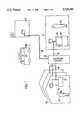
- FIG. 1is an illustrative view of an emergency call system embodying the present invention.
- reference numeral 10designates a plurality of houses or homes, each of which is connected via a telephone line 18 and a telephone station 16 to an emergency call center 12 and a hospital 14.
- each home 10there is disposed a portable transmitting device 22 which is adapted to be worn on a subscriber 20.
- a signal receiving and call device 24which is connected to the telephone line 18 of a telephone set disposed in the home 10 of the subscriber 20.
- the emergency call center 12may be organized in a private emergency service center or a fire department.
- a host monitor device 26is disposed in the emergency call center 12 and is connected to the telephone line 18.
- the portable transmitting device 22of a watch type.
- the portable transmitting device 22includes: a first housing 38 comprising a display device 30 which displays pulse wave information such as a pulse rate, a piezoelectric buzzer 32 which issues an alarm sound, a call button 34 which is operable for transmitting an emergency call of the subscriber 20, and a wearing sensor 36; a second housing 44 comprising a pulse wave sensor 42 which detects a pulse wave produced from a radial artery 40 of the subscriber 20 by being pressed on the skin directly above the artery 40; and bands 46 by which the first housing 38 and the second housing 44 are connected to each other and the portable transmitting device 22 is fixed to an arm of the subscriber 20.
- the bands 46are formed of, e.g., a synthetic resin which is elastically deformable.
- An antenna 48is provided along the bands 46.
- the pulse wave sensor 42is a pressure sensor which has the same construction as that of a conventional sensor disclosed in unexamined Japanese Patent Application laid open under Publication No. 3-15440. Namely, the pulse wave sensor 42 detects a pressure pulse wave produced from the radial artery 40 by being pressed on the skin directly above the radial artery 40.
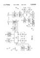
- FIG. 3shows a diagrammatic view of respective electric arrangements of the portable transmitting device 22 and the signal receiving and call device 24.
- a central processing unit (CPU) 50 of the portable transmitting device 22processes input signals according to control programs pre-stored in a read only memory (ROM) 54 by utilizing a temporary-storage function of a random access memory (RAM) 52.
- An emergency call signal and a pulse rate data signalare transmitted via a modulator 56 and a signal transmitter 58.
- FIG. 4shows a flow chart representing a control program according to which the portable transmitting device 22 operates.
- the CPU 50judges whether a pulse wave has been detected, based on the input signal from the pulse wave sensor 42. If the pulse wave sensor 42 has not detected any pulse wave, a negative judgement is made at Step S1, so that the current routine is ended. On the other hand, if the pulse wave sensor 42 has detected a pulse wave, a positive judgement is made at Step S1, so that the control goes to Step S2 to calculate a pulse rate based on a time difference between the current pulse wave and the last pulse wave according to a pre-stored expression.
- Step S3the CPU operates a display device 30 to display the thus calculated, current pulse rate of the subscriber 20, and stores the current pulse rate in the RAM 52.
- Step S4to judge whether the call button 34 has been operated. If the call button 34 has not been pushed, a negative judgement is made at Step S4, so that Steps S1 through S4 are carried out repeatedly. On the other hand, if the call button 34 has been operated, a positive judgement is made at Step S4.
- Step S4is followed by Step S5 at which the CPU 50 transmits the pulse rate data signal representing the pulse rate values that have been determined and stored in the RAM 52 in a prescribed time duration, e.g., one hour, together with an ID code signal identifying the subscriber 20, the emergency call signal, and the wearing signal supplied from the wearing sensor 36, all via the antenna 48.
- the CPU 50starts this monitoring operation upon operation of a power switch (not shown).
- the wearing sensor 36detects during the monitoring operation that the portable transmitting device 22 is not worn on the subscriber 20, the piezoelectric buzzer 32 issues an alarm sound.
- a CPU 60 of the signal receiving and call device 24 of FIG. 3,processes input signals according to control programs pre-stored in a ROM 64 by utilizing a temporary-storage function of a RAM 62.
- the CPU 60transmits the emergency call signal and an analysis of the pulse rate data to the emergency call center 12 via a modem 66 and a telephone-line interface 68.
- FIG. 5shows a flow chart representing a control program according to which the signal receiving and call device 24 operates.
- the CPU 60judges whether the CPU 60 has received signals from the portable transmitting device 22 via an antenna 70, a signal receiver 72 and a demodulator 74. If the CPU 60 has not received any signals, a negative judgement is made at Step ST1, so that the current routine is ended. On the other hand, if the CPU 60 has received the signals, a positive judgement is made at Step ST1, so that the control of the CPU 60 goes to Step ST2 to store, in the RAM 62, the pulse rate data signal, the ID code signal, the emergency call signal, and the wearing signal.
- Step ST3the CPU 60 analyzes the pulse rate data to determine the respective times of day, and total number, of occurrences of arrhythmia, tachycardia and bradycardia of the subscriber 20 in the prescribed time duration.
- Step ST3is followed by Step ST4 to operate a display device 76 to display the analyzed results obtained at Step ST3. It is possible that in particular cases a speaker 80 issue a sound or voice by being driven by a sound circuit 78.
- Step ST4is followed by Step ST5 to transmit the analysis together with the ID code signal, the emergency call signal, and the wearing signal to the emergency call center 12 via the telephone line 18.
- the host monitor device 26 disposed in the emergency call center 12is supplied with the analysis, the ID code signal identifying the subscriber 20, the emergency call signal and the wearing signal, so that the host monitor device 26 displays on an image display 82 the ID code identifying the subscriber 20, a symbol representing the emergency call, a symbol indicating that the portable transmitting device 22 is worn, or not worn, on the subscriber 20, and the times of day and total number of occurrences of arrhythmia, tachycardia and bradycardia in the last one hour on the subscriber 20.
- the operator 84 of the emergency call center 12When the operator 84 of the emergency call center 12 receives the emergency call, he or she can check the emergency call against the times of day and total number of occurrences of arrhythmia, tachycardia and bradycardia in the last one hour, i.e., pulse wave information of the subscriber 20 supplied when the call button 34 is operated by the same 20, so that the operator 84 immediately judges whether an emergency action should really be taken in response to the emergency call, without needing an additional checking operation such as a telephone call to the subscriber 20. If the operator 84 judges that an emergency action should be taken, he or she can immediately request a fire department to send an ambulance car to the house 10 of the subscriber 20, and call the hospital 14 at needed.
- the operator 84 of the emergency call center 12can recognize that the portable transmitting device 22 is worn on the subscriber 20, based on the symbol representing the wearing signal, together with the ID code identifying the subscriber 20 and the emergency call signal, so that he or she can check the emergency call more accurately. Namely, when the portable transmitting device 22 is not worn on the subscriber 20, the operator 84 can judge that no emergency action is needed, even if the pulse wave information indicates that bradycardia or other abnormal pulse wave has occurred to the subscriber 20.
- FIG. 6shows a flow chart representing a modified control program according to which the portable transmitting device 22 operates.
- the present embodimentis characterized by additionally having Step S6 between Step S3 and Step S4 of the flow chart of FIG. 4 employed in the first embodiment.
- the CPU 60identifies whether the pulse wave is abnormal, based on the pulse rate calculated at Step S2. Namely, the CPU 60 judges whether the calculated pulse rate value exceeds beyond a standard range of normal pulse rates, or whether the time different between two successive pulses is excessively long. In normal cases, a negative judgement is made at Step S6, the control of the CPU 60 goes to Step S4 and the following steps.
- Step S6the control goes to Step S5 to transmit the pulse rate data obtained in one hour before the identification of abnormality, the ID code signal, the emergency call signal and the wearing signal, to the receiving and call device 24.
- the CPU 60identifies that the pulse wave is abnormal at Step S6, the same transmission operation as that carried out in the first embodiment is automatically carried out without subscriber's pushing of the call button 34 needed in the first embodiment.
- the pulse ratesare transmitted as the physical information of the subscriber 20. It is otherwise possible to transmit, as the physical information of the subscriber 20, pulse wave information such as a wave form of a pulse wave, a magnitude of a pulse wave, and a blood pressure corresponding to a peak magnitude of a pulse wave.
- the analyzing device of the signal receiving and call device 24analyzes the respective wave forms of pulse waves, the respective magnitudes of pulse waves, and the blood pressure values.
- the pulse rates obtained through the pulse wave sensor 42are transmitted as the physical information of the subscriber 20, it is possible to employ, in place of, or in addition to the pulse wave sensor 42, an electrocardiogram sensor, a body temperature sensor, or a sweat sensor. In the later case, electrocardiograms, heart rates, body temperatures, or amounts of sweat, which are obtained through the above-mentioned sensors, may be transmitted to the signal receiving and call device 24 in place of, or in addition to the pulse rates.
- the portable transmitting device 22may comprise one or more physical information sensors and may transmit one or more sorts of physical information obtained through the sensor or sensors.
- the signal receiving and call device 24 and the host monitor device 26are connected to each other via the telephone line 18, the two devices 24, 26 may be connected to each other via a wireless communication channel.
- the pulse wave sensor 42is a pressure sensor which detects a pressure pulse wave produced from an arterial vessel 40 of a living body. It is otherwise possible to employ a pulse wave sensor which optically detects a pulse wave. In the later case, the portable transmitting device 22 may be worn on body portions of the subscriber 20 other than the arms of the same 20.
- the respective times of day, and total number, of occurrences of arrhythmia, tachycardia, and bradycardiaare transmitted as the analyzed results of the pulse wave information, together with the emergency call signal, to the emergency call center 12, it is otherwise possible to transmit at least one sort of the above-mentioned analyzed results.
- the analyzing device of the signal receiving and call device 24analyzes the physical information supplied from the portable transmitting device 22, at Step ST 3 of FIG. 5, it is possible to transmit the physical information directly, i.e., without analyzing the information, to the emergency call center 12 via the telephone line 18.
- Some sorts of physical informationmay not need any analysis, since those sorts of information, such as pulse rates, may be usable as they are in the form of measured values.
Landscapes
- Health & Medical Sciences (AREA)
- Life Sciences & Earth Sciences (AREA)
- Engineering & Computer Science (AREA)
- Biomedical Technology (AREA)
- Public Health (AREA)
- General Health & Medical Sciences (AREA)
- Medical Informatics (AREA)
- Animal Behavior & Ethology (AREA)
- Veterinary Medicine (AREA)
- Pathology (AREA)
- Molecular Biology (AREA)
- Surgery (AREA)
- Biophysics (AREA)
- Physics & Mathematics (AREA)
- Heart & Thoracic Surgery (AREA)
- Cardiology (AREA)
- Business, Economics & Management (AREA)
- General Business, Economics & Management (AREA)
- Epidemiology (AREA)
- Primary Health Care (AREA)
- Computer Networks & Wireless Communication (AREA)
- Physiology (AREA)
- Alarm Systems (AREA)
- Measuring And Recording Apparatus For Diagnosis (AREA)
- Telephonic Communication Services (AREA)
Abstract
Description
Claims (15)
Applications Claiming Priority (1)
| Application Number | Priority Date | Filing Date | Title |
|---|---|---|---|
| PCT/JP1994/001036WO2004093025A1 (en) | 1994-06-28 | 1994-06-28 | Emergency call unit |
Publications (1)
| Publication Number | Publication Date |
|---|---|
| US5729203Atrue US5729203A (en) | 1998-03-17 |
Family
ID=33257363
Family Applications (1)
| Application Number | Title | Priority Date | Filing Date |
|---|---|---|---|
| US08/436,427Expired - Fee RelatedUS5729203A (en) | 1994-06-28 | 1994-06-28 | Emergency call system |
Country Status (2)
| Country | Link |
|---|---|
| US (1) | US5729203A (en) |
| WO (1) | WO2004093025A1 (en) |
Cited By (51)
| Publication number | Priority date | Publication date | Assignee | Title |
|---|---|---|---|---|
| US5929761A (en)* | 1995-08-03 | 1999-07-27 | Siemens Nederland N.V. | Personal alarm system |
| US5971921A (en)* | 1998-06-11 | 1999-10-26 | Advanced Monitoring Devices, Inc. | Medical alarm system and methods |
| US6084525A (en)* | 1997-06-03 | 2000-07-04 | Kabushiki Kaisha Alpha Tsushin | Distress call emitting device |
| US6094140A (en)* | 1998-12-22 | 2000-07-25 | Parente; Thomas G | Portable alarm system |
| US6104295A (en)* | 1998-07-20 | 2000-08-15 | Versus Technology, Inc. | Electronic band tag and method of storing ID information therein |
| WO2000038435A3 (en)* | 1998-12-18 | 2000-10-12 | Louise Fourie | Communication device |
| US6287252B1 (en)* | 1999-06-30 | 2001-09-11 | Monitrak | Patient monitor |
| WO2002007014A1 (en)* | 2000-07-18 | 2002-01-24 | Telefonaktiebolaget L M Ericsson | Data logger for monitoring a consignment of goods |
| USD454806S1 (en) | 2001-08-10 | 2002-03-26 | Bernadette Entien | Portable combined motion detector and alarm |
| US6434429B1 (en) | 1999-06-25 | 2002-08-13 | Biotronik Mess- Und Therapiegeraete Gmbh & Co. Ingenieurbuero Berlin | Implant with close and long-range telemetry |
| US6445299B1 (en)* | 2001-01-29 | 2002-09-03 | Antonio Rojas, Jr. | Retrofit for patient call system and method therefor |
| US6470215B1 (en) | 1999-06-25 | 2002-10-22 | Biotronik Mess-Und Therapiegeraete Gmbh & Co Ingenieurbuero Berlin | Method of data transmission in implant monitoring |
| US20020160807A1 (en)* | 2001-04-27 | 2002-10-31 | Palm, Inc. | Method and apparatus for dialing an emergency service |
| US6490487B1 (en) | 1999-06-25 | 2002-12-03 | Biotronki Mess - Und Therapiegeraete Gmbh & Co. Ingenieurbuero Berlin | Transmitter of the telemetry device of an implant |
| US20030013438A1 (en)* | 2001-07-12 | 2003-01-16 | Darby George Eugene | Pocket concierge system and method |
| US6574509B1 (en) | 1999-06-25 | 2003-06-03 | Biotronik Mass- Und Therapiegerate Gmbh & Co. Ingenieurbuero Berlin | Apparatus for the transmission of data in particular from an electromedical implant |
| US20030142588A1 (en)* | 2000-04-25 | 2003-07-31 | Masanao Kawatahara | Pulsometer and measuring system comprising the same |
| US6622043B1 (en) | 1999-06-25 | 2003-09-16 | Biotronik Mess- Und Therapiegeraete Gmbh & Co. Ingenieurbuero Berlin | Method of data interrogation in implant after-care |
| WO2003082093A2 (en) | 2002-03-29 | 2003-10-09 | Koninklijke Philips Electronics N.V. | A detection and alarm system |
| US20040034289A1 (en)* | 2000-06-16 | 2004-02-19 | Eric Teller | System for monitoring health, wellness and fitness |
| US20040133081A1 (en)* | 2002-10-09 | 2004-07-08 | Eric Teller | Method and apparatus for auto journaling of continuous or discrete body states utilizing physiological and/or contextual parameters |
| US6774795B2 (en)* | 2001-06-30 | 2004-08-10 | Koninklijke Philips Electroncs N.V. | Electronic assistant incorporated in personal objects |
| US6804559B1 (en) | 1999-06-25 | 2004-10-12 | Biotronik Mess -Und Therapiegeraete Gmbh & Co. Ingenieurbuero Berlin | Electromedical implant |
| US6893395B1 (en) | 1999-06-25 | 2005-05-17 | Biotronik Mess- Und Therapiegeraete Gmbh & Co. Ingenieurbuero Berlin | Method and apparatus for data transmission between an electromedical implant and an external apparatus |
| US20050113703A1 (en)* | 2003-09-12 | 2005-05-26 | Jonathan Farringdon | Method and apparatus for measuring heart related parameters |
| US20050113650A1 (en)* | 2000-06-16 | 2005-05-26 | Christopher Pacione | System for monitoring and managing body weight and other physiological conditions including iterative and personalized planning, intervention and reporting capability |
| US20060031102A1 (en)* | 2000-06-16 | 2006-02-09 | Bodymedia, Inc. | System for detecting, monitoring, and reporting an individual's physiological or contextual status |
| US20060122474A1 (en)* | 2000-06-16 | 2006-06-08 | Bodymedia, Inc. | Apparatus for monitoring health, wellness and fitness |
| US7088235B1 (en) | 2004-08-20 | 2006-08-08 | Carricut Lee M | Method and apparatus for retrofitting a patient call system |
| US20060264730A1 (en)* | 2002-08-22 | 2006-11-23 | Bodymedia, Inc. | Apparatus for detecting human physiological and contextual information |
| US20060273916A1 (en)* | 2005-06-03 | 2006-12-07 | Lory Ortelle | Jewelry security device |
| US20070018809A1 (en)* | 2003-10-17 | 2007-01-25 | Koninklijke Philips Electronics N.V. | Device arranged for carrying out a bioelectrical interaction with an individual and a method for on-demand lead-off detection |
| US20070038038A1 (en)* | 1999-10-18 | 2007-02-15 | Bodymedia, Inc. | Wearable human physiological and environmental data sensors and reporting system therefor |
| US20070100666A1 (en)* | 2002-08-22 | 2007-05-03 | Stivoric John M | Devices and systems for contextual and physiological-based detection, monitoring, reporting, entertainment, and control of other devices |
| US7271717B1 (en) | 2005-04-26 | 2007-09-18 | Amos Vergie M | Two-way emergency alert system |
| US20080319781A1 (en)* | 2007-02-16 | 2008-12-25 | Stivoric John M | Assessment and grouping applications of lifeotypes |
| US20090177068A1 (en)* | 2002-10-09 | 2009-07-09 | Stivoric John M | Method and apparatus for providing derived glucose information utilizing physiological and/or contextual parameters |
| US20090292340A1 (en)* | 2008-05-22 | 2009-11-26 | William Mass | Regulatory Compliant Transmission of Medical Data Employing a Patient Implantable Medical Device and a Generic Network Access Device |
| US20100020941A1 (en)* | 2008-07-25 | 2010-01-28 | Walker Iii Ethan Allen | Remotely actuated two-way speakerphone for use with call-for-help systems |
| US20130161943A1 (en)* | 2011-06-29 | 2013-06-27 | Lance D. Bailey | Sandwich coupling mechanism |
| US8663106B2 (en) | 2002-08-22 | 2014-03-04 | Bodymedia, Inc. | Non-invasive temperature monitoring device |
| US20150216479A1 (en)* | 2002-04-22 | 2015-08-06 | Geelux Holding, Ltd. | Apparatus and method for measuring biologic parameters |
| CN104983408A (en)* | 2015-08-04 | 2015-10-21 | 福建工程学院 | Accidental coma diagnosis method and system |
| US9763581B2 (en) | 2003-04-23 | 2017-09-19 | P Tech, Llc | Patient monitoring apparatus and method for orthosis and other devices |
| US10582886B2 (en) | 2008-07-03 | 2020-03-10 | Masimo Corporation | Multi-stream data collection system for noninvasive measurement of blood constituents |
| US10638961B2 (en) | 2015-07-02 | 2020-05-05 | Masimo Corporation | Physiological measurement devices, systems, and methods |
| US11331019B2 (en) | 2017-08-07 | 2022-05-17 | The Research Foundation For The State University Of New York | Nanoparticle sensor having a nanofibrous membrane scaffold |
| US11638532B2 (en) | 2008-07-03 | 2023-05-02 | Masimo Corporation | User-worn device for noninvasively measuring a physiological parameter of a user |
| US12114974B2 (en) | 2020-01-13 | 2024-10-15 | Masimo Corporation | Wearable device with physiological parameters monitoring |
| US12161601B2 (en) | 2018-02-20 | 2024-12-10 | Angel Rodriguez-Cruz | Wheeleta |
| US12336796B2 (en) | 2021-07-13 | 2025-06-24 | Masimo Corporation | Wearable device with physiological parameters monitoring |
Families Citing this family (1)
| Publication number | Priority date | Publication date | Assignee | Title |
|---|---|---|---|---|
| GB2568496A (en)* | 2017-11-17 | 2019-05-22 | Michael Gale John | Alarm system |
Citations (17)
| Publication number | Priority date | Publication date | Assignee | Title |
|---|---|---|---|---|
| US3572316A (en)* | 1968-02-23 | 1971-03-23 | Chromalloy American Corp | Physiological signal monitoring system |
| US3902478A (en)* | 1971-01-07 | 1975-09-02 | Francis Konopasek | Disaster alarm |
| US3972320A (en)* | 1974-08-12 | 1976-08-03 | Gabor Ujhelyi Kalman | Patient monitoring system |
| US4173971A (en)* | 1977-08-29 | 1979-11-13 | Karz Allen E | Continuous electrocardiogram monitoring method and system for cardiac patients |
| US4524243A (en)* | 1983-07-07 | 1985-06-18 | Lifeline Systems, Inc. | Personal alarm system |
| US4622979A (en)* | 1984-03-02 | 1986-11-18 | Cardiac Monitoring, Inc. | User-worn apparatus for monitoring and recording electrocardiographic data and method of operation |
| US4819860A (en)* | 1986-01-09 | 1989-04-11 | Lloyd D. Lillie | Wrist-mounted vital functions monitor and emergency locator |
| US4889131A (en)* | 1987-12-03 | 1989-12-26 | American Health Products, Inc. | Portable belt monitor of physiological functions and sensors therefor |
| US5131400A (en)* | 1989-06-13 | 1992-07-21 | Colin Electronics Co., Ltd. | Pulse wave detecting apparatus |
| US5131390A (en)* | 1989-09-14 | 1992-07-21 | Suzuken Co. | Device for continuously measuring the skin local sweating rate |
| US5162776A (en)* | 1991-07-09 | 1992-11-10 | Lifeline Systems, Inc. | Emergency service apparatus and method |
| US5226425A (en)* | 1991-09-10 | 1993-07-13 | Ralin, Inc. | Portable ECG monitor/recorder |
| US5289824A (en)* | 1991-12-26 | 1994-03-01 | Instromedix, Inc. | Wrist-worn ECG monitor |
| US5462051A (en)* | 1994-08-31 | 1995-10-31 | Colin Corporation | Medical communication system |
| US5469146A (en)* | 1994-08-12 | 1995-11-21 | Gurler; Yener | Device for attaching to and detecting wetness in diapers |
| US5515858A (en)* | 1992-02-28 | 1996-05-14 | Myllymaeki; Matti | Wrist-held monitoring device for physical condition |
| US5581369A (en)* | 1992-09-25 | 1996-12-03 | Ralin, Inc. | Apparatus and method for communicating electrocardiographic data to a facsimile machine |
Family Cites Families (5)
| Publication number | Priority date | Publication date | Assignee | Title |
|---|---|---|---|---|
| JPH035405U (en)* | 1989-06-09 | 1991-01-21 | ||
| JPH03202046A (en)* | 1989-12-29 | 1991-09-03 | Sharp Corp | Security managing system |
| JPH04188300A (en)* | 1990-11-22 | 1992-07-06 | Iwatsu Electric Co Ltd | Abnormal signal sending device |
| JPH05288869A (en)* | 1992-04-06 | 1993-11-05 | Seiko Epson Corp | Multifunction watch |
| JPH0654812A (en)* | 1992-08-07 | 1994-03-01 | Fukuda Denshi Co Ltd | Patient monitor |
- 1994
- 1994-06-28WOPCT/JP1994/001036patent/WO2004093025A1/enactiveApplication Filing
- 1994-06-28USUS08/436,427patent/US5729203A/ennot_activeExpired - Fee Related
Patent Citations (17)
| Publication number | Priority date | Publication date | Assignee | Title |
|---|---|---|---|---|
| US3572316A (en)* | 1968-02-23 | 1971-03-23 | Chromalloy American Corp | Physiological signal monitoring system |
| US3902478A (en)* | 1971-01-07 | 1975-09-02 | Francis Konopasek | Disaster alarm |
| US3972320A (en)* | 1974-08-12 | 1976-08-03 | Gabor Ujhelyi Kalman | Patient monitoring system |
| US4173971A (en)* | 1977-08-29 | 1979-11-13 | Karz Allen E | Continuous electrocardiogram monitoring method and system for cardiac patients |
| US4524243A (en)* | 1983-07-07 | 1985-06-18 | Lifeline Systems, Inc. | Personal alarm system |
| US4622979A (en)* | 1984-03-02 | 1986-11-18 | Cardiac Monitoring, Inc. | User-worn apparatus for monitoring and recording electrocardiographic data and method of operation |
| US4819860A (en)* | 1986-01-09 | 1989-04-11 | Lloyd D. Lillie | Wrist-mounted vital functions monitor and emergency locator |
| US4889131A (en)* | 1987-12-03 | 1989-12-26 | American Health Products, Inc. | Portable belt monitor of physiological functions and sensors therefor |
| US5131400A (en)* | 1989-06-13 | 1992-07-21 | Colin Electronics Co., Ltd. | Pulse wave detecting apparatus |
| US5131390A (en)* | 1989-09-14 | 1992-07-21 | Suzuken Co. | Device for continuously measuring the skin local sweating rate |
| US5162776A (en)* | 1991-07-09 | 1992-11-10 | Lifeline Systems, Inc. | Emergency service apparatus and method |
| US5226425A (en)* | 1991-09-10 | 1993-07-13 | Ralin, Inc. | Portable ECG monitor/recorder |
| US5289824A (en)* | 1991-12-26 | 1994-03-01 | Instromedix, Inc. | Wrist-worn ECG monitor |
| US5515858A (en)* | 1992-02-28 | 1996-05-14 | Myllymaeki; Matti | Wrist-held monitoring device for physical condition |
| US5581369A (en)* | 1992-09-25 | 1996-12-03 | Ralin, Inc. | Apparatus and method for communicating electrocardiographic data to a facsimile machine |
| US5469146A (en)* | 1994-08-12 | 1995-11-21 | Gurler; Yener | Device for attaching to and detecting wetness in diapers |
| US5462051A (en)* | 1994-08-31 | 1995-10-31 | Colin Corporation | Medical communication system |
Cited By (129)
| Publication number | Priority date | Publication date | Assignee | Title |
|---|---|---|---|---|
| US5929761A (en)* | 1995-08-03 | 1999-07-27 | Siemens Nederland N.V. | Personal alarm system |
| US6084525A (en)* | 1997-06-03 | 2000-07-04 | Kabushiki Kaisha Alpha Tsushin | Distress call emitting device |
| US5971921A (en)* | 1998-06-11 | 1999-10-26 | Advanced Monitoring Devices, Inc. | Medical alarm system and methods |
| US6104295A (en)* | 1998-07-20 | 2000-08-15 | Versus Technology, Inc. | Electronic band tag and method of storing ID information therein |
| WO2000038435A3 (en)* | 1998-12-18 | 2000-10-12 | Louise Fourie | Communication device |
| US6094140A (en)* | 1998-12-22 | 2000-07-25 | Parente; Thomas G | Portable alarm system |
| US6470215B1 (en) | 1999-06-25 | 2002-10-22 | Biotronik Mess-Und Therapiegeraete Gmbh & Co Ingenieurbuero Berlin | Method of data transmission in implant monitoring |
| US6622043B1 (en) | 1999-06-25 | 2003-09-16 | Biotronik Mess- Und Therapiegeraete Gmbh & Co. Ingenieurbuero Berlin | Method of data interrogation in implant after-care |
| US6434429B1 (en) | 1999-06-25 | 2002-08-13 | Biotronik Mess- Und Therapiegeraete Gmbh & Co. Ingenieurbuero Berlin | Implant with close and long-range telemetry |
| US6893395B1 (en) | 1999-06-25 | 2005-05-17 | Biotronik Mess- Und Therapiegeraete Gmbh & Co. Ingenieurbuero Berlin | Method and apparatus for data transmission between an electromedical implant and an external apparatus |
| US6490487B1 (en) | 1999-06-25 | 2002-12-03 | Biotronki Mess - Und Therapiegeraete Gmbh & Co. Ingenieurbuero Berlin | Transmitter of the telemetry device of an implant |
| US6804559B1 (en) | 1999-06-25 | 2004-10-12 | Biotronik Mess -Und Therapiegeraete Gmbh & Co. Ingenieurbuero Berlin | Electromedical implant |
| US6574509B1 (en) | 1999-06-25 | 2003-06-03 | Biotronik Mass- Und Therapiegerate Gmbh & Co. Ingenieurbuero Berlin | Apparatus for the transmission of data in particular from an electromedical implant |
| US6287252B1 (en)* | 1999-06-30 | 2001-09-11 | Monitrak | Patient monitor |
| US20070038038A1 (en)* | 1999-10-18 | 2007-02-15 | Bodymedia, Inc. | Wearable human physiological and environmental data sensors and reporting system therefor |
| US8403845B2 (en) | 1999-10-18 | 2013-03-26 | Bodymedia, Inc. | Wearable human physiological and environmental data sensors and reporting system therefor |
| US20030142588A1 (en)* | 2000-04-25 | 2003-07-31 | Masanao Kawatahara | Pulsometer and measuring system comprising the same |
| US7179230B2 (en)* | 2000-04-25 | 2007-02-20 | Arkray, Inc. | Pulsimeter and measuring system comprising the same |
| US8961413B2 (en) | 2000-06-16 | 2015-02-24 | Bodymedia, Inc. | Wireless communications device and personal monitor |
| US9033875B2 (en) | 2000-06-16 | 2015-05-19 | Bodymedia, Inc. | Multi-sensor system, device, and method for deriving human status information |
| US20040034289A1 (en)* | 2000-06-16 | 2004-02-19 | Eric Teller | System for monitoring health, wellness and fitness |
| US8961414B2 (en) | 2000-06-16 | 2015-02-24 | Aliphcom | Apparatus for monitoring health, wellness and fitness |
| US7689437B1 (en) | 2000-06-16 | 2010-03-30 | Bodymedia, Inc. | System for monitoring health, wellness and fitness |
| US20070173705A1 (en)* | 2000-06-16 | 2007-07-26 | Eric Teller | Apparatus for monitoring health, wellness and fitness |
| US8073707B2 (en) | 2000-06-16 | 2011-12-06 | Bodymedia, Inc. | System for detecting, monitoring, and reporting an individual's physiological or contextual status |
| US20090118590A1 (en)* | 2000-06-16 | 2009-05-07 | Eric Teller | Multi-sensor system, device, and method for deriving human status information |
| US20050113650A1 (en)* | 2000-06-16 | 2005-05-26 | Christopher Pacione | System for monitoring and managing body weight and other physiological conditions including iterative and personalized planning, intervention and reporting capability |
| US20080183052A1 (en)* | 2000-06-16 | 2008-07-31 | Eric Teller | Multi-sensor system, device, and method for deriving human status information |
| US20080183051A1 (en)* | 2000-06-16 | 2008-07-31 | Eric Teller | Multi-sensor system, device, and method for deriving human status information |
| US8398546B2 (en) | 2000-06-16 | 2013-03-19 | Bodymedia, Inc. | System for monitoring and managing body weight and other physiological conditions including iterative and personalized planning, intervention and reporting capability |
| US20060031102A1 (en)* | 2000-06-16 | 2006-02-09 | Bodymedia, Inc. | System for detecting, monitoring, and reporting an individual's physiological or contextual status |
| US20060224051A1 (en)* | 2000-06-16 | 2006-10-05 | Bodymedia, Inc. | Wireless communications device and personal monitor |
| US20080171918A1 (en)* | 2000-06-16 | 2008-07-17 | Eric Teller | Multi-sensor system, device, and method for deriving human status information |
| US20060122474A1 (en)* | 2000-06-16 | 2006-06-08 | Bodymedia, Inc. | Apparatus for monitoring health, wellness and fitness |
| EP1702560A1 (en)* | 2000-06-23 | 2006-09-20 | Bodymedia, Inc. | System for monitoring health, wellness and fitness |
| WO2002007014A1 (en)* | 2000-07-18 | 2002-01-24 | Telefonaktiebolaget L M Ericsson | Data logger for monitoring a consignment of goods |
| US6445299B1 (en)* | 2001-01-29 | 2002-09-03 | Antonio Rojas, Jr. | Retrofit for patient call system and method therefor |
| US7346333B2 (en) | 2001-04-27 | 2008-03-18 | Palm, Inc. | Method and apparatus for effectuating a predetermined communications connection |
| US20020160807A1 (en)* | 2001-04-27 | 2002-10-31 | Palm, Inc. | Method and apparatus for dialing an emergency service |
| US6774795B2 (en)* | 2001-06-30 | 2004-08-10 | Koninklijke Philips Electroncs N.V. | Electronic assistant incorporated in personal objects |
| US20030013438A1 (en)* | 2001-07-12 | 2003-01-16 | Darby George Eugene | Pocket concierge system and method |
| USD454806S1 (en) | 2001-08-10 | 2002-03-26 | Bernadette Entien | Portable combined motion detector and alarm |
| WO2003082093A3 (en)* | 2002-03-29 | 2003-12-18 | Koninkl Philips Electronics Nv | A detection and alarm system |
| WO2003082093A2 (en) | 2002-03-29 | 2003-10-09 | Koninklijke Philips Electronics N.V. | A detection and alarm system |
| US9408572B2 (en)* | 2002-04-22 | 2016-08-09 | Geelux Holdings, Ltd. | Apparatus and method for measuring biologic parameters |
| US11045092B2 (en)* | 2002-04-22 | 2021-06-29 | Geelux Holdings, Ltd. | Apparatus and method for measuring biologic parameters |
| US20190099084A1 (en)* | 2002-04-22 | 2019-04-04 | Geelux Holdings, Ltd. | Apparatus and method for measuring biologic parameters |
| US10052030B2 (en) | 2002-04-22 | 2018-08-21 | Geelux Holdings, Ltd. | Apparatus and method for measuring biologic parameters |
| US9833150B2 (en)* | 2002-04-22 | 2017-12-05 | Geelux Holdings, Ltd. | Apparatus and method for measuring biologic parameters |
| US9826906B2 (en)* | 2002-04-22 | 2017-11-28 | Geelux Holdings, Ltd. | Apparatus and method for measuring biologic parameters |
| US20150216479A1 (en)* | 2002-04-22 | 2015-08-06 | Geelux Holding, Ltd. | Apparatus and method for measuring biologic parameters |
| US20160270726A1 (en)* | 2002-04-22 | 2016-09-22 | Geelux Holdings, Ltd. | Apparatus and method for measuring biologic parameters |
| US9204806B2 (en) | 2002-08-22 | 2015-12-08 | Bodymedia, Inc. | Apparatus using temperature data to make predictions about an individual |
| US20070100666A1 (en)* | 2002-08-22 | 2007-05-03 | Stivoric John M | Devices and systems for contextual and physiological-based detection, monitoring, reporting, entertainment, and control of other devices |
| US20060264730A1 (en)* | 2002-08-22 | 2006-11-23 | Bodymedia, Inc. | Apparatus for detecting human physiological and contextual information |
| US9168001B2 (en) | 2002-08-22 | 2015-10-27 | Bodymedia, Inc. | Adhesively mounted apparatus for determining physiological and contextual status |
| US8663106B2 (en) | 2002-08-22 | 2014-03-04 | Bodymedia, Inc. | Non-invasive temperature monitoring device |
| US20040133081A1 (en)* | 2002-10-09 | 2004-07-08 | Eric Teller | Method and apparatus for auto journaling of continuous or discrete body states utilizing physiological and/or contextual parameters |
| US8157731B2 (en) | 2002-10-09 | 2012-04-17 | Bodymedia, Inc. | Method and apparatus for auto journaling of continuous or discrete body states utilizing physiological and/or contextual parameters |
| US20090177068A1 (en)* | 2002-10-09 | 2009-07-09 | Stivoric John M | Method and apparatus for providing derived glucose information utilizing physiological and/or contextual parameters |
| US9763581B2 (en) | 2003-04-23 | 2017-09-19 | P Tech, Llc | Patient monitoring apparatus and method for orthosis and other devices |
| US20100286532A1 (en)* | 2003-09-12 | 2010-11-11 | Bodymedia, Inc. | Wearable apparatus for measuring heart-related parameters and deriving human status parameters from sensed physiological and contextual parameters |
| US7502643B2 (en) | 2003-09-12 | 2009-03-10 | Bodymedia, Inc. | Method and apparatus for measuring heart related parameters |
| US8369936B2 (en) | 2003-09-12 | 2013-02-05 | Bodymedia, Inc. | Wearable apparatus for measuring heart-related parameters and deriving human status parameters from sensed physiological and contextual parameters |
| US20050113703A1 (en)* | 2003-09-12 | 2005-05-26 | Jonathan Farringdon | Method and apparatus for measuring heart related parameters |
| US20070018809A1 (en)* | 2003-10-17 | 2007-01-25 | Koninklijke Philips Electronics N.V. | Device arranged for carrying out a bioelectrical interaction with an individual and a method for on-demand lead-off detection |
| US7453354B2 (en)* | 2003-10-17 | 2008-11-18 | Koninklijke Philips Electronics, N.V. | Device arranged for carrying out a bioelectrical interaction with an individual and a method for on-demand lead-off detection |
| US7088235B1 (en) | 2004-08-20 | 2006-08-08 | Carricut Lee M | Method and apparatus for retrofitting a patient call system |
| US7271717B1 (en) | 2005-04-26 | 2007-09-18 | Amos Vergie M | Two-way emergency alert system |
| US20060273916A1 (en)* | 2005-06-03 | 2006-12-07 | Lory Ortelle | Jewelry security device |
| US7551079B2 (en)* | 2005-06-03 | 2009-06-23 | Lory Ortelle | Jewelry security device |
| US8275635B2 (en) | 2007-02-16 | 2012-09-25 | Bodymedia, Inc. | Integration of lifeotypes with devices and systems |
| US20080319855A1 (en)* | 2007-02-16 | 2008-12-25 | Stivoric John M | Advertising and marketing based on lifeotypes |
| US20080319781A1 (en)* | 2007-02-16 | 2008-12-25 | Stivoric John M | Assessment and grouping applications of lifeotypes |
| US20080320029A1 (en)* | 2007-02-16 | 2008-12-25 | Stivoric John M | Lifeotype interfaces |
| US20080319787A1 (en)* | 2007-02-16 | 2008-12-25 | Stivoric John M | Integration of lifeotypes with devices and systems |
| US20080320030A1 (en)* | 2007-02-16 | 2008-12-25 | Stivoric John M | Lifeotype markup language |
| US8382590B2 (en) | 2007-02-16 | 2013-02-26 | Bodymedia, Inc. | Entertainment, gaming and interactive spaces based on lifeotypes |
| US20090006457A1 (en)* | 2007-02-16 | 2009-01-01 | Stivoric John M | Lifeotypes |
| US20080319786A1 (en)* | 2007-02-16 | 2008-12-25 | Stivoric John M | Publishing and insurance applications of lifeotypes |
| US20080319796A1 (en)* | 2007-02-16 | 2008-12-25 | Stivoric John M | Medical applications of lifeotypes |
| US8103346B2 (en) | 2008-05-22 | 2012-01-24 | Cardiac Pacemakers, Inc. | Regulatory compliant transmission of medical data employing a patient implantable medical device and a generic network access device |
| US20090292340A1 (en)* | 2008-05-22 | 2009-11-26 | William Mass | Regulatory Compliant Transmission of Medical Data Employing a Patient Implantable Medical Device and a Generic Network Access Device |
| US8265757B2 (en) | 2008-05-22 | 2012-09-11 | Cardiac Pacemakers, Inc. | Regulatory compliant transmission of medical data employing a patient implantable medical device and a generic network access device |
| US8437854B2 (en) | 2008-05-22 | 2013-05-07 | Cardiac Pacemakers, Inc. | Regulatory compliant transmission of medical data employing a patient implantable medical device and a generic network access device |
| US8700158B2 (en) | 2008-05-22 | 2014-04-15 | Cardiac Pacemakers, Inc. | Regulatory compliant transmission of medical data employing a patient implantable medical device and a generic network access |
| US10945648B2 (en) | 2008-07-03 | 2021-03-16 | Masimo Corporation | User-worn device for noninvasively measuring a physiological parameter of a user |
| US11484229B2 (en) | 2008-07-03 | 2022-11-01 | Masimo Corporation | User-worn device for noninvasively measuring a physiological parameter of a user |
| US12036009B1 (en) | 2008-07-03 | 2024-07-16 | Masimo Corporation | User-worn device for noninvasively measuring a physiological parameter of a user |
| US12023139B1 (en) | 2008-07-03 | 2024-07-02 | Masimo Corporation | User-worn device for noninvasively measuring a physiological parameter of a user |
| US11751773B2 (en) | 2008-07-03 | 2023-09-12 | Masimo Corporation | Emitter arrangement for physiological measurements |
| US10582886B2 (en) | 2008-07-03 | 2020-03-10 | Masimo Corporation | Multi-stream data collection system for noninvasive measurement of blood constituents |
| US10588553B2 (en) | 2008-07-03 | 2020-03-17 | Masimo Corporation | Multi-stream data collection system for noninvasive measurement of blood constituents |
| US10588554B2 (en) | 2008-07-03 | 2020-03-17 | Masimo Corporation | Multi-stream data collection system for noninvasive measurement of blood constituents |
| US10610138B2 (en) | 2008-07-03 | 2020-04-07 | Masimo Corporation | Multi-stream data collection system for noninvasive measurement of blood constituents |
| US10617338B2 (en) | 2008-07-03 | 2020-04-14 | Masimo Corporation | Multi-stream data collection system for noninvasive measurement of blood constituents |
| US10624564B1 (en) | 2008-07-03 | 2020-04-21 | Masimo Corporation | Multi-stream data collection system for noninvasive measurement of blood constituents |
| US10624563B2 (en) | 2008-07-03 | 2020-04-21 | Masimo Corporation | Multi-stream data collection system for noninvasive measurement of blood constituents |
| US10631765B1 (en) | 2008-07-03 | 2020-04-28 | Masimo Corporation | Multi-stream data collection system for noninvasive measurement of blood constituents |
| US11647914B2 (en) | 2008-07-03 | 2023-05-16 | Masimo Corporation | User-worn device for noninvasively measuring a physiological parameter of a user |
| US11642037B2 (en) | 2008-07-03 | 2023-05-09 | Masimo Corporation | User-worn device for noninvasively measuring a physiological parameter of a user |
| US11642036B2 (en) | 2008-07-03 | 2023-05-09 | Masimo Corporation | User-worn device for noninvasively measuring a physiological parameter of a user |
| US11638532B2 (en) | 2008-07-03 | 2023-05-02 | Masimo Corporation | User-worn device for noninvasively measuring a physiological parameter of a user |
| US11484230B2 (en) | 2008-07-03 | 2022-11-01 | Masimo Corporation | User-worn device for noninvasively measuring a physiological parameter of a user |
| US10702194B1 (en) | 2008-07-03 | 2020-07-07 | Masimo Corporation | Multi-stream data collection system for noninvasive measurement of blood constituents |
| US10702195B1 (en) | 2008-07-03 | 2020-07-07 | Masimo Corporation | Multi-stream data collection system for noninvasive measurement of blood constituents |
| US10709366B1 (en) | 2008-07-03 | 2020-07-14 | Masimo Corporation | Multi-stream data collection system for noninvasive measurement of blood constituents |
| US11426103B2 (en) | 2008-07-03 | 2022-08-30 | Masimo Corporation | Multi-stream data collection system for noninvasive measurement of blood constituents |
| US10743803B2 (en) | 2008-07-03 | 2020-08-18 | Masimo Corporation | Multi-stream data collection system for noninvasive measurement of blood constituents |
| US10758166B2 (en) | 2008-07-03 | 2020-09-01 | Masimo Corporation | Multi-stream data collection system for noninvasive measurement of blood constituents |
| US10912500B2 (en) | 2008-07-03 | 2021-02-09 | Masimo Corporation | Multi-stream data collection system for noninvasive measurement of blood constituents |
| US10912502B2 (en) | 2008-07-03 | 2021-02-09 | Masimo Corporation | User-worn device for noninvasively measuring a physiological parameter of a user |
| US10912501B2 (en) | 2008-07-03 | 2021-02-09 | Masimo Corporation | User-worn device for noninvasively measuring a physiological parameter of a user |
| US20100020941A1 (en)* | 2008-07-25 | 2010-01-28 | Walker Iii Ethan Allen | Remotely actuated two-way speakerphone for use with call-for-help systems |
| US8451984B2 (en)* | 2008-07-25 | 2013-05-28 | Ethan Allen Walker, III | Remotely actuated two-way speakerphone for use with call-for-help systems |
| US8938858B2 (en)* | 2011-06-29 | 2015-01-27 | Lance D. Bailey | Sandwich coupling mechanism |
| US20130161943A1 (en)* | 2011-06-29 | 2013-06-27 | Lance D. Bailey | Sandwich coupling mechanism |
| US10646146B2 (en) | 2015-07-02 | 2020-05-12 | Masimo Corporation | Physiological monitoring devices, systems, and methods |
| US10687744B1 (en) | 2015-07-02 | 2020-06-23 | Masimo Corporation | Physiological measurement devices, systems, and methods |
| US10687743B1 (en) | 2015-07-02 | 2020-06-23 | Masimo Corporation | Physiological measurement devices, systems, and methods |
| US10687745B1 (en) | 2015-07-02 | 2020-06-23 | Masimo Corporation | Physiological monitoring devices, systems, and methods |
| US10722159B2 (en) | 2015-07-02 | 2020-07-28 | Masimo Corporation | Physiological monitoring devices, systems, and methods |
| US10638961B2 (en) | 2015-07-02 | 2020-05-05 | Masimo Corporation | Physiological measurement devices, systems, and methods |
| CN104983408A (en)* | 2015-08-04 | 2015-10-21 | 福建工程学院 | Accidental coma diagnosis method and system |
| CN104983408B (en)* | 2015-08-04 | 2018-02-23 | 福建工程学院 | A kind of unexpected stupor diagnostic method and system |
| US11331019B2 (en) | 2017-08-07 | 2022-05-17 | The Research Foundation For The State University Of New York | Nanoparticle sensor having a nanofibrous membrane scaffold |
| US12161601B2 (en) | 2018-02-20 | 2024-12-10 | Angel Rodriguez-Cruz | Wheeleta |
| US12114974B2 (en) | 2020-01-13 | 2024-10-15 | Masimo Corporation | Wearable device with physiological parameters monitoring |
| US12336796B2 (en) | 2021-07-13 | 2025-06-24 | Masimo Corporation | Wearable device with physiological parameters monitoring |
Also Published As
| Publication number | Publication date |
|---|---|
| WO2004093025A1 (en) | 2004-10-28 |
Similar Documents
| Publication | Publication Date | Title |
|---|---|---|
| US5729203A (en) | Emergency call system | |
| US6102856A (en) | Wearable vital sign monitoring system | |
| US5367555A (en) | Medical data reporter | |
| US10709330B2 (en) | Ambulatory medical telemetry device having an audio indicator | |
| US6485418B2 (en) | Health monitoring system | |
| US5873369A (en) | System for monitoring health conditions of an individual and a method thereof | |
| EP1494190B1 (en) | Mobile communication device and method for monitoring and transmitting of bio-data and environment-data in an emergency case | |
| US5462051A (en) | Medical communication system | |
| US8265907B2 (en) | System and a method for physiological monitoring | |
| US7996187B2 (en) | Method and system for health monitoring | |
| EP1893076B1 (en) | Personal health monitor and a method for health monitioring | |
| US6485415B1 (en) | Medical monitoring system | |
| US6870484B1 (en) | Patient monitoring systems having two-way communication | |
| EP1679672B1 (en) | Portable pulse monitoring device and method of its operation | |
| US20040199056A1 (en) | Body monitoring using local area wireless interfaces | |
| JPH1170086A (en) | Emergency informing system | |
| WO1994021171B1 (en) | Biomedical response monitor - exercise equipment and technique | |
| WO1999004685A1 (en) | A personal health status alarm method | |
| US5586552A (en) | Physical-information detecting system | |
| US20020109595A1 (en) | Personal alert device | |
| JP2000037357A (en) | Physical information management system | |
| GB2517179A (en) | Monitoring device and system | |
| JP4419261B2 (en) | Atherosclerosis diagnostic device | |
| JP2956605B2 (en) | Patient monitoring system | |
| JPH0646983B2 (en) | Medical communication device |
Legal Events
| Date | Code | Title | Description |
|---|---|---|---|
| AS | Assignment | Owner name:COLIN CORPORATION, JAPAN Free format text:ASSIGNMENT OF ASSIGNORS INTEREST;ASSIGNORS:OKA, TOHRU;SUZUKI, HIDENORI;REEL/FRAME:007591/0122 Effective date:19950518 | |
| FEPP | Fee payment procedure | Free format text:PAYOR NUMBER ASSIGNED (ORIGINAL EVENT CODE: ASPN); ENTITY STATUS OF PATENT OWNER: SMALL ENTITY | |
| FPAY | Fee payment | Year of fee payment:4 | |
| AS | Assignment | Owner name:COLIN MEDICAL TECHNOLOGY CORPORATION, JAPAN Free format text:ASSIGNMENT OF ASSIGNORS INTEREST;ASSIGNOR:COLIN CORPORATION;REEL/FRAME:014420/0448 Effective date:20040205 | |
| REMI | Maintenance fee reminder mailed | ||
| LAPS | Lapse for failure to pay maintenance fees | ||
| STCH | Information on status: patent discontinuation | Free format text:PATENT EXPIRED DUE TO NONPAYMENT OF MAINTENANCE FEES UNDER 37 CFR 1.362 | |
| FP | Lapsed due to failure to pay maintenance fee | Effective date:20060317 | |
| AS | Assignment | Owner name:OMRON HEALTHCARE CO., LTD., JAPAN Free format text:ASSIGNMENT OF ASSIGNORS INTEREST;ASSIGNOR:COLIN MEDICAL TECHNOLOGY CORPORATION;REEL/FRAME:017846/0738 Effective date:20060626 |