US5729065A - Magnetic bearing cell with rotor and stator - Google Patents
Magnetic bearing cell with rotor and statorDownload PDFInfo
- Publication number
- US5729065A US5729065AUS08/491,987US49198795AUS5729065AUS 5729065 AUS5729065 AUS 5729065AUS 49198795 AUS49198795 AUS 49198795AUS 5729065 AUS5729065 AUS 5729065A
- Authority
- US
- United States
- Prior art keywords
- rings
- stator
- rotor
- magnetic
- annular coils
- Prior art date
- Legal status (The legal status is an assumption and is not a legal conclusion. Google has not performed a legal analysis and makes no representation as to the accuracy of the status listed.)
- Expired - Lifetime
Links
Images

Classifications
- F—MECHANICAL ENGINEERING; LIGHTING; HEATING; WEAPONS; BLASTING
- F16—ENGINEERING ELEMENTS AND UNITS; GENERAL MEASURES FOR PRODUCING AND MAINTAINING EFFECTIVE FUNCTIONING OF MACHINES OR INSTALLATIONS; THERMAL INSULATION IN GENERAL
- F16C—SHAFTS; FLEXIBLE SHAFTS; ELEMENTS OR CRANKSHAFT MECHANISMS; ROTARY BODIES OTHER THAN GEARING ELEMENTS; BEARINGS
- F16C32/00—Bearings not otherwise provided for
- F16C32/04—Bearings not otherwise provided for using magnetic or electric supporting means
- F16C32/0406—Magnetic bearings
- F16C32/044—Active magnetic bearings
- F16C32/0459—Details of the magnetic circuit
- F16C32/0461—Details of the magnetic circuit of stationary parts of the magnetic circuit
- F16C32/0465—Details of the magnetic circuit of stationary parts of the magnetic circuit with permanent magnets provided in the magnetic circuit of the electromagnets
- F—MECHANICAL ENGINEERING; LIGHTING; HEATING; WEAPONS; BLASTING
- F16—ENGINEERING ELEMENTS AND UNITS; GENERAL MEASURES FOR PRODUCING AND MAINTAINING EFFECTIVE FUNCTIONING OF MACHINES OR INSTALLATIONS; THERMAL INSULATION IN GENERAL
- F16C—SHAFTS; FLEXIBLE SHAFTS; ELEMENTS OR CRANKSHAFT MECHANISMS; ROTARY BODIES OTHER THAN GEARING ELEMENTS; BEARINGS
- F16C32/00—Bearings not otherwise provided for
- F16C32/04—Bearings not otherwise provided for using magnetic or electric supporting means
- F16C32/0406—Magnetic bearings
- F16C32/0408—Passive magnetic bearings
- F16C32/041—Passive magnetic bearings with permanent magnets on one part attracting the other part
- F16C32/0412—Passive magnetic bearings with permanent magnets on one part attracting the other part for radial load mainly
- F16C32/0414—Passive magnetic bearings with permanent magnets on one part attracting the other part for radial load mainly with facing axial projections
- F—MECHANICAL ENGINEERING; LIGHTING; HEATING; WEAPONS; BLASTING
- F16—ENGINEERING ELEMENTS AND UNITS; GENERAL MEASURES FOR PRODUCING AND MAINTAINING EFFECTIVE FUNCTIONING OF MACHINES OR INSTALLATIONS; THERMAL INSULATION IN GENERAL
- F16C—SHAFTS; FLEXIBLE SHAFTS; ELEMENTS OR CRANKSHAFT MECHANISMS; ROTARY BODIES OTHER THAN GEARING ELEMENTS; BEARINGS
- F16C32/00—Bearings not otherwise provided for
- F16C32/04—Bearings not otherwise provided for using magnetic or electric supporting means
- F16C32/0406—Magnetic bearings
- F16C32/044—Active magnetic bearings
- F16C32/0474—Active magnetic bearings for rotary movement
- F16C32/0476—Active magnetic bearings for rotary movement with active support of one degree of freedom, e.g. axial magnetic bearings
- F—MECHANICAL ENGINEERING; LIGHTING; HEATING; WEAPONS; BLASTING
- F16—ENGINEERING ELEMENTS AND UNITS; GENERAL MEASURES FOR PRODUCING AND MAINTAINING EFFECTIVE FUNCTIONING OF MACHINES OR INSTALLATIONS; THERMAL INSULATION IN GENERAL
- F16C—SHAFTS; FLEXIBLE SHAFTS; ELEMENTS OR CRANKSHAFT MECHANISMS; ROTARY BODIES OTHER THAN GEARING ELEMENTS; BEARINGS
- F16C2300/00—Application independent of particular apparatuses
- F16C2300/02—General use or purpose, i.e. no use, purpose, special adaptation or modification indicated or a wide variety of uses mentioned
Definitions
- the inventionrelates to a rotationally symmetrical magnetic bearing cell with a rotor arranged to rotate about the central axis of the cell having a shaft and at least two axially magnetised permanent magnetic rings fitted an axial distance apart on the shaft, as well as a stator having pole components and two annular coils associated with the rotor end faces whereby the rotor and stator components are arranged in such a way with respect to each other that the permanent magnets generate a magnetic flux which surrounds the central axis toroidally embracing the annular coils.
- a magnetic bearing cell having these characteristicsis known from DE-C 34 09 047. Its rotor has two axially magnetised permanent magnetic rings which generate the magnetic flux toroidally about the central axis embracing the annular coils. The magnetic flux penetrates the permanent magnetic rings of the rotor which are axially arranged behind each other as well as the peripheral pole components so that a high radial rigidity is attained.
- the bearingis unstable in the axial direction and therefore requires an active control with respect to this direction.
- annular coilsare associated with each of the rotor end faces. Each of these annular coils also generates a toroidal magnetic flux which surrounds the central axis and which superimposes itself on the magnetic flux generated by the permanent magnetic rings.
- the active controlis preferably selected in such a manner that the annular coils do not carry a current when the rotor has attained its nominal position. If the rotor deviates from its nominal position in the axial direction, then a current is applied to the annular coils.
- the magnitude of the current and its directiondepend on the magnitude and the direction of the deviation.
- the toroidal magnetic flux generated by the annular coilshas the same or the opposite direction with respect to the magnetic flux produced by the permanent magnetic rings.
- this taskis solved by associating pole components of magnetically conductive material with the peripheral regions of the two axially outer permanent magnetic rings to direct the magnetic flux generated by the annular cells into two substantially independent magnetic flux circuits.
- the proposed measuresfavour the formation of control fluxes directly associated with the annular coils. These cause the magnetic fluxes which are generated by the annular coils and which are substantially independent of each other to only penetrate the respective pole components surrounding the annular coils, a part of the permanent magnetic ring in the vicinity as well as the respective axial and peripheral slit between rotor and stator. Greater resistances are thus not present in these magnetic flux circuits.
- the magnetic fluxes which chiefly contribute to the axial control of the magnetic fieldneed no longer penetrate the other still present components (permanent magnets, attenuation discs) and slits. Thus the complexity required for the annular coils with regard to size and power supply does thus no longer depend on the number of permanent magnetic rings present.
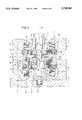
- FIG. 1is a magnetic bearing cell with two permanent magnetic rings and
- FIG. 2is a magnetic bearing cell with four permanent magnetic rings
- the magnetic bearing cell 1 shown in the drawing figureembraces rotor 2 and stator 3.
- Components of the rotor 2are shaft 4 and the permanent magnetic rings 5 and 6 attached to shaft 4.
- Inner hub rings 8, 9are provided for attachment of the permanent magnetic rings 5, 6 to shaft 4.
- the toroidal magnetic flux surrounding central axis 10 which is produced by the permanent magnetic rings 5, 6is indicated by arrow 11.
- Stator 3embraces with respect to central axis 10 rotationally symmetrically designed pole components 12, 13, the common cross section of which is substantially C-shaped.
- Annular coils 14, 15are located in face region C.
- the inner sections 16, 17form pole surfaces 18, 19 which face the permanent magnetic rings 5, 6 of rotor 2.
- a sensor arrangement 21 as well as an electronic controller 22 which is shown as a blockare provided to control the current flow through annular coils 14, 15.
- Annular disc 24which is made of non-magnetisable material of high electrical conductivity, like copper, for example, engages in slit 23 between the permanent magnetic rings 5 and 6.
- Annular disc 24has a peripheral cylindrical section 25, which rests against the insides of components 12, 13. In the case of substantially axially directed relative movements, eddy currents are generated in the annular disc 24 and also in the cylindrical section 25, which produce the desired damping effect.
- the cylindrical section 25has a centering function and moreover it promotes the removal of heat caused by the eddy currents.
- stator components 26, 27are associated with the peripheral regions of permanent magnetic rings 5, 6 which are formed as stator rings surrounding the permanent magnet rings 5, 6. They are made of a magnetically well conducting material and have the effect that annular coils 14, 15 generate--in contrast to magnetic flux circuit 11 produced by the permanent magnetic rings 5, 6--two magnetic flux circuits 28, 29.
- stator permanent magnetic rings 5 and 30are provided.
- the slit 31 between permanent magnetic rings 6 and 30is engaged by an annular disc 32, which carries a further, resting permanent magnetic ring 33.
- the radial dimensions of this stator permanent magnetic ring 33correspond to the dimensions of rotor permanent magnetic rings 6 and 30.
- the disc 32is made of non-magnetisable material (stainless steel, for example) and also has the peripheral cylindrical section 34, which rests against the inside of component 13 for the purpose of centering. If, in addition, the material has a high electrical conductance, then it will contribute to an improvement of the damping characteristics.
- Magnet rings 5, 6, 30, 33are magnetised in the axial direction in such a way that attracting forces act between them. Together with pole components 12, 13, 16, 17, they form a magnetic circuit (arrow 11) which is responsible for the radial rigidity.
- Outer reinforcement rings 35, 36, 37embrace the rotating permanent magnetic rings and protect these against being damaged by the influence of the relatively high centrifugal forces during the rotation.
- the outer permanent magnetic rings 5 and 30are associated at their peripheral regions with stator rings 26, 27 which cause the desired splitting of the magnetic field generated by annular coils 14, 15 into two separate magnetic fluxes (arrows 28, 29). If in the areas of the stator rings 28, 29, Belleville spring washers 38 or packs of Belleville spring washers are necessary for mutual tensioning of the various ring components 25, 26, 27, 34, then it is expedient to provide Belleville spring washers made of a magnetically well conducting material. These may replace a stator ring 28 or 29, or may be additionally present.
Landscapes
- Engineering & Computer Science (AREA)
- General Engineering & Computer Science (AREA)
- Mechanical Engineering (AREA)
- Physics & Mathematics (AREA)
- Electromagnetism (AREA)
- Magnetic Bearings And Hydrostatic Bearings (AREA)
Abstract
Description
The invention relates to a rotationally symmetrical magnetic bearing cell with a rotor arranged to rotate about the central axis of the cell having a shaft and at least two axially magnetised permanent magnetic rings fitted an axial distance apart on the shaft, as well as a stator having pole components and two annular coils associated with the rotor end faces whereby the rotor and stator components are arranged in such a way with respect to each other that the permanent magnets generate a magnetic flux which surrounds the central axis toroidally embracing the annular coils.
A magnetic bearing cell having these characteristics is known from DE-C 34 09 047. Its rotor has two axially magnetised permanent magnetic rings which generate the magnetic flux toroidally about the central axis embracing the annular coils. The magnetic flux penetrates the permanent magnetic rings of the rotor which are axially arranged behind each other as well as the peripheral pole components so that a high radial rigidity is attained. The bearing is unstable in the axial direction and therefore requires an active control with respect to this direction. For this purpose annular coils are associated with each of the rotor end faces. Each of these annular coils also generates a toroidal magnetic flux which surrounds the central axis and which superimposes itself on the magnetic flux generated by the permanent magnetic rings. The active control is preferably selected in such a manner that the annular coils do not carry a current when the rotor has attained its nominal position. If the rotor deviates from its nominal position in the axial direction, then a current is applied to the annular coils. The magnitude of the current and its direction depend on the magnitude and the direction of the deviation. Depending on the direction of the current, the toroidal magnetic flux generated by the annular coils has the same or the opposite direction with respect to the magnetic flux produced by the permanent magnetic rings.
In order to improve radial rigidity of a magnetic bearing of the aforementioned kind, it is proposed to increase the number of permanent magnetic rings on the rotor and to provide in addition on the stator at least one additional permanent magnetic ring which is also axially magnetised (refer to DE-A 41 06 063). These measures increase the flux produced by the permanent magnets, i.e. increase the axial forces and thus give rise to the desired increase in radial rigidity. In order to be able to perform their control task, the annular coils must be capable of generating control fluxes which compensate the increased axial forces. The pre-requisite for this is an increased cross section for the annular coils as well as increased complexity regarding current generation and active control for the coils.
It is the task of the present invention to design a magnetic bearing cell of the aforementioned kind in such a way, that in spite of an improvement in radial rigidity by increasing the number of permanent magnetic rings, active control complexity is not increased.
According to the present invention this task is solved by associating pole components of magnetically conductive material with the peripheral regions of the two axially outer permanent magnetic rings to direct the magnetic flux generated by the annular cells into two substantially independent magnetic flux circuits.
The proposed measures favour the formation of control fluxes directly associated with the annular coils. These cause the magnetic fluxes which are generated by the annular coils and which are substantially independent of each other to only penetrate the respective pole components surrounding the annular coils, a part of the permanent magnetic ring in the vicinity as well as the respective axial and peripheral slit between rotor and stator. Greater resistances are thus not present in these magnetic flux circuits. The magnetic fluxes which chiefly contribute to the axial control of the magnetic field need no longer penetrate the other still present components (permanent magnets, attenuation discs) and slits. Thus the complexity required for the annular coils with regard to size and power supply does thus no longer depend on the number of permanent magnetic rings present.
Further advantages and details of the present invention shall be explained by referring to the design examples of drawing FIGS. 1 and 2. Shown in
drawing FIG. 1 is a magnetic bearing cell with two permanent magnetic rings and
drawing FIG. 2 is a magnetic bearing cell with four permanent magnetic rings,
The magnetic bearingcell 1 shown in the drawing figure embracesrotor 2 andstator 3.
Components of therotor 2 are shaft 4 and the permanentmagnetic rings Inner hub rings 8, 9 are provided for attachment of the permanentmagnetic rings central axis 10 which is produced by the permanentmagnetic rings arrow 11.
In the design example according to drawing FIG. 2, three rotating and axially magnetised permanentmagnetic rings slit 31 between permanentmagnetic rings annular disc 32, which carries a further, resting permanentmagnetic ring 33. The radial dimensions of this stator permanentmagnetic ring 33 correspond to the dimensions of rotor permanentmagnetic rings disc 32 is made of non-magnetisable material (stainless steel, for example) and also has the peripheralcylindrical section 34, which rests against the inside ofcomponent 13 for the purpose of centering. If, in addition, the material has a high electrical conductance, then it will contribute to an improvement of the damping characteristics.
The outer permanentmagnetic rings stator rings annular coils arrows 28, 29). If in the areas of thestator rings spring washers 38 or packs of Belleville spring washers are necessary for mutual tensioning of thevarious ring components stator ring
Claims (3)
1. A rotationally symmetrical magnetic bearing cell (1) comprising:
a rotor (2) arranged to rotate about a central axis (10) of the cell (1) and having a shaft (4) and at least two axially magnetised permanent magnetic rings (5, 6, 30) fitted an axial distance apart on the shaft, as well as
a stator (3), which has a first plurality of pole components (12, 13, 16, 17) and two annular coils (14, 15) which are associated with a respective rotor end face,
whereby the rotor and stator are arranged with respect to each other in such a manner that the permanent magnetic rings (5, 6, 30) produce a magnetic flux (11) which toroidally surrounds the central axis (10) and embraces the annular coils (14, 15)
wherein
a second plurality of pole components (26, 27, 38) made of a magnetically well conducting material are associated with respective peripheral regions of each of the two axially outer permanent magnetic rings (5, 6 or 5, 30), whereby said second plurality of pole components direct a magnetic flux generated by the annular coils (14, 15) into two substantially independent magnetic flux circuits (28, 29).
2. Magnetic bearing cell according to claim 1, wherein the permanent magnetic rings (5, 6, or 5, 30) are directly surrounded by stator rings (26, 27).
3. Magnetic bearing cell according to claim 1, wherein in addition to, or instead of one stator ring (26, 27), one or several Belleville spring washers (38) made of a magnetically well conducting material are present.
Applications Claiming Priority (3)
| Application Number | Priority Date | Filing Date | Title |
|---|---|---|---|
| DE4301076.8 | 1993-01-16 | ||
| DE4301076ADE4301076A1 (en) | 1993-01-16 | 1993-01-16 | Magnetic bearing cell with rotor and stator |
| PCT/EP1993/003540WO1994016235A1 (en) | 1993-01-16 | 1993-12-15 | Magnetic bearing cell with rotor and stator |
Publications (1)
| Publication Number | Publication Date |
|---|---|
| US5729065Atrue US5729065A (en) | 1998-03-17 |
Family
ID=6478346
Family Applications (1)
| Application Number | Title | Priority Date | Filing Date |
|---|---|---|---|
| US08/491,987Expired - LifetimeUS5729065A (en) | 1993-01-16 | 1993-12-15 | Magnetic bearing cell with rotor and stator |
Country Status (5)
| Country | Link |
|---|---|
| US (1) | US5729065A (en) |
| EP (1) | EP0679230B1 (en) |
| JP (1) | JP3786420B2 (en) |
| DE (2) | DE4301076A1 (en) |
| WO (1) | WO1994016235A1 (en) |
Cited By (36)
| Publication number | Priority date | Publication date | Assignee | Title |
|---|---|---|---|---|
| US6087750A (en)* | 1999-05-18 | 2000-07-11 | Pacific Scientific Electro Kinetics Division | Permanent magnet generator |
| US6198194B1 (en) | 1999-09-17 | 2001-03-06 | Trw Inc. | Segmented rotor for an electric machine |
| US6215219B1 (en)* | 1998-07-28 | 2001-04-10 | Samsung Electronics Co., Ltd. | Bearing system and spindle motor assembly adopting the same |
| US6268674B1 (en)* | 1998-05-15 | 2001-07-31 | Kabushiki Kaisha Toshiba | Magnetic bearing apparatus |
| US6503050B2 (en)* | 2000-12-18 | 2003-01-07 | Applied Materials Inc. | Turbo-molecular pump having enhanced pumping capacity |
| US6538403B2 (en) | 2000-01-07 | 2003-03-25 | Black & Decker Inc. | Brushless DC motor sensor control system and method |
| US6570285B2 (en)* | 1999-12-27 | 2003-05-27 | Ebara Corporation | Magnetic bearing apparatus having a protective non-magnetic can |
| US6617720B1 (en) | 1998-04-08 | 2003-09-09 | Kadant Black Clawson Inc. | Integrated paper pulp and process machinery having integrated drive and control and methods of use thereof |
| US20030187321A1 (en)* | 2001-04-30 | 2003-10-02 | Jan Hoffmann | Method for adjusting the position of a rotating component which is borne by means of a permanent-magnet |
| US20030189383A1 (en)* | 2000-09-02 | 2003-10-09 | Fremerey Johan K | Magnetic bearing arrangement |
| US20030222516A1 (en)* | 2000-01-07 | 2003-12-04 | Cleanthous Aris C. | Brushless dc motor |
| US20040021381A1 (en)* | 2000-07-13 | 2004-02-05 | Garvey Seamus Dominic | Magnetic bearings |
| US20040115038A1 (en)* | 2001-02-16 | 2004-06-17 | Peter Nuesser | Device for axially conveying fluids |
| US20050029886A1 (en)* | 2001-10-18 | 2005-02-10 | Paul Van Tichelen | Axial flux permanent magnet generator/motor |
| US20050200218A1 (en)* | 2002-04-12 | 2005-09-15 | Fremerey Johan K. | Magnetic guiding device |
| US20050204479A1 (en)* | 2004-03-18 | 2005-09-22 | Maytag Corporation | Self-cleaning spinner top |
| US7058291B2 (en) | 2000-01-07 | 2006-06-06 | Black & Decker Inc. | Brushless DC motor |
| US20080309188A1 (en)* | 2007-05-09 | 2008-12-18 | David Gregory Calley | Electrical output generating devices and driven electrical devices with reduced flux leakage using permanent magnet components, and methods of making and using the same |
| US20090021089A1 (en)* | 2005-05-17 | 2009-01-22 | Denso Corporation | Motor and control unit thereof |
| US20090208771A1 (en)* | 2007-05-09 | 2009-08-20 | Thomas Janecek | Powdered metal manufacturing method and devices |
| US20090218897A1 (en)* | 2005-12-21 | 2009-09-03 | Thales | Damper |
| US20100109452A1 (en)* | 2008-11-03 | 2010-05-06 | Motor Excellence Llc | Transverse and/or commutated flux system rotor concepts |
| US20110025161A1 (en)* | 2009-07-30 | 2011-02-03 | Bison Gear & Engineering Corp. | Axial flux stator and method of manufacture thereof |
| US20110109190A1 (en)* | 2009-11-09 | 2011-05-12 | Yasuaki Aoyama | Rotary electrical machine |
| US20110169365A1 (en)* | 2010-03-15 | 2011-07-14 | Motor Excellence Llc | Transverse and/or commutated flux systems configured to provide reduced flux leakage, hysteresis loss reduction, and phase matching |
| KR101064226B1 (en) | 2009-06-18 | 2011-09-14 | 한국과학기술연구원 | Hybrid thrust magnetic bearing |
| US20110291507A1 (en)* | 2010-06-01 | 2011-12-01 | Post Richard F | Magnetic bearing element with adjustable stiffness |
| US8222786B2 (en) | 2010-03-15 | 2012-07-17 | Motor Excellence Llc | Transverse and/or commutated flux systems having phase offset |
| US8395291B2 (en) | 2010-03-15 | 2013-03-12 | Electric Torque Machines, Inc. | Transverse and/or commutated flux systems for electric bicycles |
| US8405275B2 (en) | 2010-11-17 | 2013-03-26 | Electric Torque Machines, Inc. | Transverse and/or commutated flux systems having segmented stator laminations |
| CN103591139A (en)* | 2013-11-22 | 2014-02-19 | 江苏理工学院 | Passive radial permanent magnet bearing for high-speed rotor |
| US8836196B2 (en) | 2010-11-17 | 2014-09-16 | Electric Torque Machines, Inc. | Transverse and/or commutated flux systems having segmented stator laminations |
| US8952590B2 (en) | 2010-11-17 | 2015-02-10 | Electric Torque Machines Inc | Transverse and/or commutated flux systems having laminated and powdered metal portions |
| CN112065903A (en)* | 2020-09-14 | 2020-12-11 | 浙江工业大学 | A rigid linear permanent magnet spring |
| CN117307603A (en)* | 2023-09-11 | 2023-12-29 | 淮阴工学院 | A hybrid excitation magnetic bearing with independent radial and axial suspension forces |
| WO2024033312A1 (en)* | 2022-08-09 | 2024-02-15 | Leybold Gmbh | Eddy current damper and vacuum pump |
Families Citing this family (4)
| Publication number | Priority date | Publication date | Assignee | Title |
|---|---|---|---|---|
| FR2732734B1 (en)* | 1995-04-07 | 1997-06-27 | Aerospatiale | MINIATURE MAGNETIC BEARING HAS AT LEAST ONE ACTIVE AXIS |
| DE19825854A1 (en)* | 1998-06-10 | 1999-12-16 | Leybold Vakuum Gmbh | Magnetic bearing cell |
| CN101832335B (en)* | 2010-05-25 | 2012-06-20 | 南京化工职业技术学院 | Permanent magnet biased axial-radial magnetic bearing |
| CN111609035A (en)* | 2020-04-17 | 2020-09-01 | 北京航空航天大学宁波创新研究院 | Active and passive magnetic bearing |
Citations (8)
| Publication number | Priority date | Publication date | Assignee | Title |
|---|---|---|---|---|
| EP0155624A1 (en)* | 1984-03-13 | 1985-09-25 | Forschungszentrum Jülich Gmbh | Magnetic bearing with a three-axle stabilisation |
| EP0332979A2 (en)* | 1988-03-12 | 1989-09-20 | Forschungszentrum Jülich Gmbh | Magnetic support with permanent magnets for absorption of the radial bearing stresses |
| EP0467341A1 (en)* | 1990-07-17 | 1992-01-22 | Koyo Seiko Co., Ltd. | Superconducting bearing device |
| US5084644A (en)* | 1990-12-20 | 1992-01-28 | Nova Corporation Of Alberta | Control of magnetization of a machine with axial magnetic bearings |
| US5250865A (en)* | 1992-04-30 | 1993-10-05 | Avcon - Advanced Controls Technology, Inc. | Electromagnetic thrust bearing for coupling a rotatable member to a stationary member |
| US5315197A (en)* | 1992-04-30 | 1994-05-24 | Avcon - Advance Controls Technology, Inc. | Electromagnetic thrust bearing using passive and active magnets, for coupling a rotatable member to a stationary member |
| US5386166A (en)* | 1991-02-27 | 1995-01-31 | Leybold Ag | Magnetic bearing cell |
| US5514924A (en)* | 1992-04-30 | 1996-05-07 | AVCON--Advanced Control Technology, Inc. | Magnetic bearing providing radial and axial load support for a shaft |
Family Cites Families (5)
| Publication number | Priority date | Publication date | Assignee | Title |
|---|---|---|---|---|
| US3698775A (en)* | 1970-04-01 | 1972-10-17 | Technical Management Services | Magnetic support and motor structure |
| DE2919236C2 (en)* | 1979-05-12 | 1982-08-12 | Kernforschungsanlage Jülich GmbH, 5170 Jülich | Magnetic floating bearing for one rotor |
| DE3239328C2 (en)* | 1982-10-23 | 1993-12-23 | Pfeiffer Vakuumtechnik | Magnetically mounted turbomolecular pump with vibration damping |
| SU1395860A1 (en)* | 1986-01-29 | 1988-05-15 | Московский Институт Радиотехники,Электроники И Автоматики | Controlled magnetic support |
| DE4020726A1 (en)* | 1990-06-29 | 1992-01-02 | Marinescu Geb Bikales | Magnetic bearing for electric motor rotor shaft - has two axially adjacent annular coils and annular magnet separated by ring poles |
- 1993
- 1993-01-16DEDE4301076Apatent/DE4301076A1/ennot_activeWithdrawn
- 1993-12-15JPJP51639494Apatent/JP3786420B2/ennot_activeExpired - Fee Related
- 1993-12-15EPEP94903777Apatent/EP0679230B1/ennot_activeExpired - Lifetime
- 1993-12-15DEDE59303784Tpatent/DE59303784D1/ennot_activeExpired - Lifetime
- 1993-12-15WOPCT/EP1993/003540patent/WO1994016235A1/enactiveIP Right Grant
- 1993-12-15USUS08/491,987patent/US5729065A/ennot_activeExpired - Lifetime
Patent Citations (9)
| Publication number | Priority date | Publication date | Assignee | Title |
|---|---|---|---|---|
| EP0155624A1 (en)* | 1984-03-13 | 1985-09-25 | Forschungszentrum Jülich Gmbh | Magnetic bearing with a three-axle stabilisation |
| US4620752A (en)* | 1984-03-13 | 1986-11-04 | Kernforschungsanlage Julich Gesellschaft Mit Beschrankter Haftung | Magnetic bearing having triaxial position stabilization |
| EP0332979A2 (en)* | 1988-03-12 | 1989-09-20 | Forschungszentrum Jülich Gmbh | Magnetic support with permanent magnets for absorption of the radial bearing stresses |
| EP0467341A1 (en)* | 1990-07-17 | 1992-01-22 | Koyo Seiko Co., Ltd. | Superconducting bearing device |
| US5084644A (en)* | 1990-12-20 | 1992-01-28 | Nova Corporation Of Alberta | Control of magnetization of a machine with axial magnetic bearings |
| US5386166A (en)* | 1991-02-27 | 1995-01-31 | Leybold Ag | Magnetic bearing cell |
| US5250865A (en)* | 1992-04-30 | 1993-10-05 | Avcon - Advanced Controls Technology, Inc. | Electromagnetic thrust bearing for coupling a rotatable member to a stationary member |
| US5315197A (en)* | 1992-04-30 | 1994-05-24 | Avcon - Advance Controls Technology, Inc. | Electromagnetic thrust bearing using passive and active magnets, for coupling a rotatable member to a stationary member |
| US5514924A (en)* | 1992-04-30 | 1996-05-07 | AVCON--Advanced Control Technology, Inc. | Magnetic bearing providing radial and axial load support for a shaft |
Cited By (80)
| Publication number | Priority date | Publication date | Assignee | Title |
|---|---|---|---|---|
| US6617720B1 (en) | 1998-04-08 | 2003-09-09 | Kadant Black Clawson Inc. | Integrated paper pulp and process machinery having integrated drive and control and methods of use thereof |
| US6268674B1 (en)* | 1998-05-15 | 2001-07-31 | Kabushiki Kaisha Toshiba | Magnetic bearing apparatus |
| US6215219B1 (en)* | 1998-07-28 | 2001-04-10 | Samsung Electronics Co., Ltd. | Bearing system and spindle motor assembly adopting the same |
| US6087750A (en)* | 1999-05-18 | 2000-07-11 | Pacific Scientific Electro Kinetics Division | Permanent magnet generator |
| US6198194B1 (en) | 1999-09-17 | 2001-03-06 | Trw Inc. | Segmented rotor for an electric machine |
| US6570285B2 (en)* | 1999-12-27 | 2003-05-27 | Ebara Corporation | Magnetic bearing apparatus having a protective non-magnetic can |
| US20030222516A1 (en)* | 2000-01-07 | 2003-12-04 | Cleanthous Aris C. | Brushless dc motor |
| US6538403B2 (en) | 2000-01-07 | 2003-03-25 | Black & Decker Inc. | Brushless DC motor sensor control system and method |
| US7058291B2 (en) | 2000-01-07 | 2006-06-06 | Black & Decker Inc. | Brushless DC motor |
| US6975050B2 (en) | 2000-01-07 | 2005-12-13 | Black & Decker Inc. | Brushless DC motor |
| US7301252B2 (en)* | 2000-07-13 | 2007-11-27 | Rolls-Royce Plc | Magnetic bearings |
| US7485994B2 (en) | 2000-07-13 | 2009-02-03 | Rolls-Royce Plc | Magnetic bearings |
| US20040021381A1 (en)* | 2000-07-13 | 2004-02-05 | Garvey Seamus Dominic | Magnetic bearings |
| US20080100162A1 (en)* | 2000-07-13 | 2008-05-01 | Rolls-Royce Plc | Magnetic Bearings |
| US7023117B2 (en)* | 2000-09-02 | 2006-04-04 | Forschungazentrum Julich Gmbh | Magnetic bearing arrangement |
| US20030189383A1 (en)* | 2000-09-02 | 2003-10-09 | Fremerey Johan K | Magnetic bearing arrangement |
| US6503050B2 (en)* | 2000-12-18 | 2003-01-07 | Applied Materials Inc. | Turbo-molecular pump having enhanced pumping capacity |
| US7467929B2 (en) | 2001-02-16 | 2008-12-23 | Berlin Heart Gmbh | Device for axially conveying fluids |
| US20040115038A1 (en)* | 2001-02-16 | 2004-06-17 | Peter Nuesser | Device for axially conveying fluids |
| US20080091265A1 (en)* | 2001-02-16 | 2008-04-17 | Berlin Heart Gmbh | Device for axially conveying fluids |
| US7934909B2 (en) | 2001-02-16 | 2011-05-03 | Berlin Heart Gmbh | Device for axially conveying fluids |
| US7229474B2 (en) | 2001-04-30 | 2007-06-12 | Berlin Heart Ag | Method for controlling the position of a permanent magnetically supported rotating component |
| US20030187321A1 (en)* | 2001-04-30 | 2003-10-02 | Jan Hoffmann | Method for adjusting the position of a rotating component which is borne by means of a permanent-magnet |
| US20050029886A1 (en)* | 2001-10-18 | 2005-02-10 | Paul Van Tichelen | Axial flux permanent magnet generator/motor |
| US7157829B2 (en)* | 2001-10-18 | 2007-01-02 | Vlaamse Instelling Voor Technologisch Onderzoek (V.I.T.O) | Axial flux permanent magnet generator/motor |
| US7307365B2 (en) | 2002-04-12 | 2007-12-11 | Forschungszentrum Julich Gmbh | Magnetic guiding device |
| US20050200218A1 (en)* | 2002-04-12 | 2005-09-15 | Fremerey Johan K. | Magnetic guiding device |
| US20050204479A1 (en)* | 2004-03-18 | 2005-09-22 | Maytag Corporation | Self-cleaning spinner top |
| US20090021089A1 (en)* | 2005-05-17 | 2009-01-22 | Denso Corporation | Motor and control unit thereof |
| US8120215B2 (en)* | 2005-05-17 | 2012-02-21 | Denso Corporation | Motor and control unit thereof |
| US20090218897A1 (en)* | 2005-12-21 | 2009-09-03 | Thales | Damper |
| US7868511B2 (en) | 2007-05-09 | 2011-01-11 | Motor Excellence, Llc | Electrical devices using disk and non-disk shaped rotors |
| US20090160288A1 (en)* | 2007-05-09 | 2009-06-25 | David Gregory Calley | Electrical output generating devices and driven electrical devices using electromagnetic rotors, and methods of making and using the same |
| US20080309188A1 (en)* | 2007-05-09 | 2008-12-18 | David Gregory Calley | Electrical output generating devices and driven electrical devices with reduced flux leakage using permanent magnet components, and methods of making and using the same |
| US20090206696A1 (en)* | 2007-05-09 | 2009-08-20 | David Gregory Calley | Electrical output generating and driven devices using disk and non-disk shaped rotors, and methods of making and using the same |
| US20110221298A1 (en)* | 2007-05-09 | 2011-09-15 | Motor Excellence, Llc | Electrical devices having tape wound core laminate rotor or stator elements |
| US7800275B2 (en) | 2007-05-09 | 2010-09-21 | Motor Excellence, Llc | Electrical devices using electronmagnetic rotors |
| US20100295410A1 (en)* | 2007-05-09 | 2010-11-25 | Motor Excellence Llc. | Electrical devices using electromagnetic rotors |
| US7989084B2 (en) | 2007-05-09 | 2011-08-02 | Motor Excellence, Llc | Powdered metal manufacturing method and devices |
| US7863797B2 (en) | 2007-05-09 | 2011-01-04 | Motor Excellence, Llc | Electrical devices using electromagnetic rotors |
| US20090208771A1 (en)* | 2007-05-09 | 2009-08-20 | Thomas Janecek | Powdered metal manufacturing method and devices |
| US7973446B2 (en) | 2007-05-09 | 2011-07-05 | Motor Excellence, Llc | Electrical devices having tape wound core laminate rotor or stator elements |
| US7876019B2 (en) | 2007-05-09 | 2011-01-25 | Motor Excellence, Llc | Electrical devices with reduced flux leakage using permanent magnet components |
| US8030819B2 (en) | 2008-11-03 | 2011-10-04 | Motor Excellence, Llc | Transverse and/or commutated flux system rotor concepts |
| US20100109453A1 (en)* | 2008-11-03 | 2010-05-06 | Motor Excellence Llc | Polyphase transverse and/or commutated flux systems |
| US7923886B2 (en) | 2008-11-03 | 2011-04-12 | Motor Excellence, Llc | Transverse and/or commutated flux system rotor concepts |
| US8242658B2 (en) | 2008-11-03 | 2012-08-14 | Electric Torque Machines Inc. | Transverse and/or commutated flux system rotor concepts |
| US8193679B2 (en) | 2008-11-03 | 2012-06-05 | Motor Excellence Llc | Polyphase transverse and/or commutated flux systems |
| US7868508B2 (en) | 2008-11-03 | 2011-01-11 | Motor Excellence, Llc | Polyphase transverse and/or commutated flux systems |
| US20100109452A1 (en)* | 2008-11-03 | 2010-05-06 | Motor Excellence Llc | Transverse and/or commutated flux system rotor concepts |
| US7851965B2 (en) | 2008-11-03 | 2010-12-14 | Motor Excellence, Llc | Transverse and/or commutated flux system stator concepts |
| US20110050010A1 (en)* | 2008-11-03 | 2011-03-03 | Motor Excellence Llc | Transverse and/or commutated flux system stator concepts |
| US7994678B2 (en) | 2008-11-03 | 2011-08-09 | Motor Excellence, Llc | Polyphase transverse and/or commutated flux systems |
| US8008821B2 (en) | 2008-11-03 | 2011-08-30 | Motor Excellence, Llc | Transverse and/or commutated flux system stator concepts |
| US20100109462A1 (en)* | 2008-11-03 | 2010-05-06 | Motor Excellence Llc | Transverse and/or commutated flux system stator concepts |
| KR101064226B1 (en) | 2009-06-18 | 2011-09-14 | 한국과학기술연구원 | Hybrid thrust magnetic bearing |
| US20110025161A1 (en)* | 2009-07-30 | 2011-02-03 | Bison Gear & Engineering Corp. | Axial flux stator and method of manufacture thereof |
| US9287739B2 (en) | 2009-07-30 | 2016-03-15 | Bison Gear & Engineering Corp. | Axial flux stator and method of manufacture thereof |
| US9583982B2 (en)* | 2009-07-30 | 2017-02-28 | Bison Gear & Engineering Corp. | Axial flux stator and method of manufacture thereof |
| US20110109190A1 (en)* | 2009-11-09 | 2011-05-12 | Yasuaki Aoyama | Rotary electrical machine |
| US8680739B2 (en)* | 2009-11-09 | 2014-03-25 | Hitachi, Ltd. | Rotary electrical machine |
| US8053944B2 (en) | 2010-03-15 | 2011-11-08 | Motor Excellence, Llc | Transverse and/or commutated flux systems configured to provide reduced flux leakage, hysteresis loss reduction, and phase matching |
| US8395291B2 (en) | 2010-03-15 | 2013-03-12 | Electric Torque Machines, Inc. | Transverse and/or commutated flux systems for electric bicycles |
| US20110169365A1 (en)* | 2010-03-15 | 2011-07-14 | Motor Excellence Llc | Transverse and/or commutated flux systems configured to provide reduced flux leakage, hysteresis loss reduction, and phase matching |
| US8415848B2 (en) | 2010-03-15 | 2013-04-09 | Electric Torque Machines, Inc. | Transverse and/or commutated flux systems configured to provide reduced flux leakage, hysteresis loss reduction, and phase matching |
| US8222786B2 (en) | 2010-03-15 | 2012-07-17 | Motor Excellence Llc | Transverse and/or commutated flux systems having phase offset |
| US8760023B2 (en)* | 2010-03-15 | 2014-06-24 | Electric Torque Machines, Inc. | Transverse and/or commutated flux systems having phase offset |
| US8581463B2 (en)* | 2010-06-01 | 2013-11-12 | Lawrence Livermore National Laboratory, Llc | Magnetic bearing element with adjustable stiffness |
| US20110291507A1 (en)* | 2010-06-01 | 2011-12-01 | Post Richard F | Magnetic bearing element with adjustable stiffness |
| US8854171B2 (en) | 2010-11-17 | 2014-10-07 | Electric Torque Machines Inc. | Transverse and/or commutated flux system coil concepts |
| US8836196B2 (en) | 2010-11-17 | 2014-09-16 | Electric Torque Machines, Inc. | Transverse and/or commutated flux systems having segmented stator laminations |
| US8952590B2 (en) | 2010-11-17 | 2015-02-10 | Electric Torque Machines Inc | Transverse and/or commutated flux systems having laminated and powdered metal portions |
| US8405275B2 (en) | 2010-11-17 | 2013-03-26 | Electric Torque Machines, Inc. | Transverse and/or commutated flux systems having segmented stator laminations |
| CN103591139B (en)* | 2013-11-22 | 2015-08-12 | 江苏理工学院 | Passive radial permanent magnet bearing for high-speed rotor |
| CN103591139A (en)* | 2013-11-22 | 2014-02-19 | 江苏理工学院 | Passive radial permanent magnet bearing for high-speed rotor |
| CN112065903A (en)* | 2020-09-14 | 2020-12-11 | 浙江工业大学 | A rigid linear permanent magnet spring |
| WO2024033312A1 (en)* | 2022-08-09 | 2024-02-15 | Leybold Gmbh | Eddy current damper and vacuum pump |
| GB2621342B (en)* | 2022-08-09 | 2025-04-02 | Leybold Gmbh | Vacuum pump |
| CN117307603A (en)* | 2023-09-11 | 2023-12-29 | 淮阴工学院 | A hybrid excitation magnetic bearing with independent radial and axial suspension forces |
| CN117307603B (en)* | 2023-09-11 | 2024-06-11 | 淮阴工学院 | A hybrid excitation magnetic bearing with independent radial and axial suspension forces |
Also Published As
| Publication number | Publication date |
|---|---|
| DE4301076A1 (en) | 1994-07-21 |
| WO1994016235A1 (en) | 1994-07-21 |
| JP3786420B2 (en) | 2006-06-14 |
| EP0679230B1 (en) | 1996-09-11 |
| DE59303784D1 (en) | 1996-10-17 |
| EP0679230A1 (en) | 1995-11-02 |
Similar Documents
| Publication | Publication Date | Title |
|---|---|---|
| US5729065A (en) | Magnetic bearing cell with rotor and stator | |
| US5386166A (en) | Magnetic bearing cell | |
| SU1299522A3 (en) | Magnetic support for stabilizing shaft position | |
| SU1711681A3 (en) | Magnetic support unit of permanent magnet rotor | |
| US6359357B1 (en) | Combination radial and thrust magnetic bearing | |
| EP0191225B1 (en) | Magnetic bearing device | |
| US4983870A (en) | Radial magnetic bearing | |
| EP0130541B1 (en) | Flywheel apparatus | |
| US6121704A (en) | Magnetic bearing | |
| US5811904A (en) | Permanent magnet dynamo electric machine | |
| US3888553A (en) | Levitated rotary magnetic device | |
| JP4852609B2 (en) | Rotor shaft for magnetic bearing device | |
| US4748361A (en) | Permanent magnet electric motor | |
| US6833643B2 (en) | Magnetic bearing with damping | |
| US20110163622A1 (en) | Combination Radial/Axial Electromagnetic Actuator | |
| US4682067A (en) | Synchronous electric motor having a disc-shaped permanent magnet rotor | |
| US4340261A (en) | Magnetic bearing arrangement | |
| JPH09509465A (en) | Magnetic bearing cell having a rotor and a stator | |
| JPH06242133A (en) | Speed sensor of vehicle wheel | |
| US20150330444A1 (en) | Symmetrical electromagnetic actuator | |
| JP2017082757A (en) | Method for reducing stray vector magnetic field of vacuum pump or rotary unit, vacuum pump and rotary unit | |
| US5471105A (en) | Null flux magnetic bearing with cross-connected loop portions | |
| JP2886891B2 (en) | Axial magnetic bearing assembly | |
| CA2822707C (en) | Radial magnetic bearing for magnetic support of a rotor | |
| US6770995B1 (en) | Passive radial magnetic bearing |
Legal Events
| Date | Code | Title | Description |
|---|---|---|---|
| AS | Assignment | Owner name:FORSCHUNGESENTRUM JULICH, GMBH, GERMANY Free format text:ASSIGNMENT OF ASSIGNORS INTEREST;ASSIGNORS:FREMERY, JOHAN K.;SCHNEIDER, HELMUT;REIMER, PETER;AND OTHERS;REEL/FRAME:007781/0390 Effective date:19950717 Owner name:LEYBOLD AKTIENGESELLSCHAFT, GERMANY Free format text:ASSIGNMENT OF ASSIGNORS INTEREST;ASSIGNORS:FREMERY, JOHAN K.;SCHNEIDER, HELMUT;REIMER, PETER;AND OTHERS;REEL/FRAME:007781/0390 Effective date:19950717 | |
| STCF | Information on status: patent grant | Free format text:PATENTED CASE | |
| CC | Certificate of correction | ||
| FPAY | Fee payment | Year of fee payment:4 | |
| FPAY | Fee payment | Year of fee payment:8 | |
| FEPP | Fee payment procedure | Free format text:PAYER NUMBER DE-ASSIGNED (ORIGINAL EVENT CODE: RMPN); ENTITY STATUS OF PATENT OWNER: LARGE ENTITY | |
| FPAY | Fee payment | Year of fee payment:12 |