US5728624A - Bonded wafer processing - Google Patents
Bonded wafer processingDownload PDFInfo
- Publication number
- US5728624A US5728624AUS08/573,551US57355195AUS5728624AUS 5728624 AUS5728624 AUS 5728624AUS 57355195 AUS57355195 AUS 57355195AUS 5728624 AUS5728624 AUS 5728624A
- Authority
- US
- United States
- Prior art keywords
- wafer
- silicon
- bonding
- oxide
- layer
- Prior art date
- Legal status (The legal status is an assumption and is not a legal conclusion. Google has not performed a legal analysis and makes no representation as to the accuracy of the status listed.)
- Expired - Lifetime
Links
Images


Classifications
- H—ELECTRICITY
- H10—SEMICONDUCTOR DEVICES; ELECTRIC SOLID-STATE DEVICES NOT OTHERWISE PROVIDED FOR
- H10D—INORGANIC ELECTRIC SEMICONDUCTOR DEVICES
- H10D86/00—Integrated devices formed in or on insulating or conducting substrates, e.g. formed in silicon-on-insulator [SOI] substrates or on stainless steel or glass substrates
- H10D86/80—Integrated devices formed in or on insulating or conducting substrates, e.g. formed in silicon-on-insulator [SOI] substrates or on stainless steel or glass substrates characterised by multiple passive components, e.g. resistors, capacitors or inductors
- H10D86/85—Integrated devices formed in or on insulating or conducting substrates, e.g. formed in silicon-on-insulator [SOI] substrates or on stainless steel or glass substrates characterised by multiple passive components, e.g. resistors, capacitors or inductors characterised by only passive components
- H—ELECTRICITY
- H01—ELECTRIC ELEMENTS
- H01L—SEMICONDUCTOR DEVICES NOT COVERED BY CLASS H10
- H01L21/00—Processes or apparatus adapted for the manufacture or treatment of semiconductor or solid state devices or of parts thereof
- H01L21/02—Manufacture or treatment of semiconductor devices or of parts thereof
- H01L21/04—Manufacture or treatment of semiconductor devices or of parts thereof the devices having potential barriers, e.g. a PN junction, depletion layer or carrier concentration layer
- H01L21/18—Manufacture or treatment of semiconductor devices or of parts thereof the devices having potential barriers, e.g. a PN junction, depletion layer or carrier concentration layer the devices having semiconductor bodies comprising elements of Group IV of the Periodic Table or AIIIBV compounds with or without impurities, e.g. doping materials
- H01L21/20—Deposition of semiconductor materials on a substrate, e.g. epitaxial growth solid phase epitaxy
- H01L21/2003—Deposition of semiconductor materials on a substrate, e.g. epitaxial growth solid phase epitaxy characterised by the substrate
- H01L21/2007—Bonding of semiconductor wafers to insulating substrates or to semiconducting substrates using an intermediate insulating layer
- H—ELECTRICITY
- H01—ELECTRIC ELEMENTS
- H01L—SEMICONDUCTOR DEVICES NOT COVERED BY CLASS H10
- H01L21/00—Processes or apparatus adapted for the manufacture or treatment of semiconductor or solid state devices or of parts thereof
- H01L21/02—Manufacture or treatment of semiconductor devices or of parts thereof
- H01L21/04—Manufacture or treatment of semiconductor devices or of parts thereof the devices having potential barriers, e.g. a PN junction, depletion layer or carrier concentration layer
- H01L21/18—Manufacture or treatment of semiconductor devices or of parts thereof the devices having potential barriers, e.g. a PN junction, depletion layer or carrier concentration layer the devices having semiconductor bodies comprising elements of Group IV of the Periodic Table or AIIIBV compounds with or without impurities, e.g. doping materials
- H01L21/26—Bombardment with radiation
- H01L21/263—Bombardment with radiation with high-energy radiation
- H01L21/265—Bombardment with radiation with high-energy radiation producing ion implantation
- H—ELECTRICITY
- H01—ELECTRIC ELEMENTS
- H01L—SEMICONDUCTOR DEVICES NOT COVERED BY CLASS H10
- H01L21/00—Processes or apparatus adapted for the manufacture or treatment of semiconductor or solid state devices or of parts thereof
- H01L21/70—Manufacture or treatment of devices consisting of a plurality of solid state components formed in or on a common substrate or of parts thereof; Manufacture of integrated circuit devices or of parts thereof
- H01L21/71—Manufacture of specific parts of devices defined in group H01L21/70
- H01L21/76—Making of isolation regions between components
- H01L21/762—Dielectric regions, e.g. EPIC dielectric isolation, LOCOS; Trench refilling techniques, SOI technology, use of channel stoppers
- H01L21/7624—Dielectric regions, e.g. EPIC dielectric isolation, LOCOS; Trench refilling techniques, SOI technology, use of channel stoppers using semiconductor on insulator [SOI] technology
- H01L21/76264—SOI together with lateral isolation, e.g. using local oxidation of silicon, or dielectric or polycristalline material refilled trench or air gap isolation regions, e.g. completely isolated semiconductor islands
- H01L21/76275—Vertical isolation by bonding techniques
- H—ELECTRICITY
- H01—ELECTRIC ELEMENTS
- H01L—SEMICONDUCTOR DEVICES NOT COVERED BY CLASS H10
- H01L21/00—Processes or apparatus adapted for the manufacture or treatment of semiconductor or solid state devices or of parts thereof
- H01L21/70—Manufacture or treatment of devices consisting of a plurality of solid state components formed in or on a common substrate or of parts thereof; Manufacture of integrated circuit devices or of parts thereof
- H01L21/71—Manufacture of specific parts of devices defined in group H01L21/70
- H01L21/76—Making of isolation regions between components
- H01L21/762—Dielectric regions, e.g. EPIC dielectric isolation, LOCOS; Trench refilling techniques, SOI technology, use of channel stoppers
- H01L21/7624—Dielectric regions, e.g. EPIC dielectric isolation, LOCOS; Trench refilling techniques, SOI technology, use of channel stoppers using semiconductor on insulator [SOI] technology
- H01L21/76264—SOI together with lateral isolation, e.g. using local oxidation of silicon, or dielectric or polycristalline material refilled trench or air gap isolation regions, e.g. completely isolated semiconductor islands
- H01L21/76283—Lateral isolation by refilling of trenches with dielectric material
- H—ELECTRICITY
- H01—ELECTRIC ELEMENTS
- H01L—SEMICONDUCTOR DEVICES NOT COVERED BY CLASS H10
- H01L21/00—Processes or apparatus adapted for the manufacture or treatment of semiconductor or solid state devices or of parts thereof
- H01L21/70—Manufacture or treatment of devices consisting of a plurality of solid state components formed in or on a common substrate or of parts thereof; Manufacture of integrated circuit devices or of parts thereof
- H01L21/71—Manufacture of specific parts of devices defined in group H01L21/70
- H01L21/76—Making of isolation regions between components
- H01L21/762—Dielectric regions, e.g. EPIC dielectric isolation, LOCOS; Trench refilling techniques, SOI technology, use of channel stoppers
- H01L21/7624—Dielectric regions, e.g. EPIC dielectric isolation, LOCOS; Trench refilling techniques, SOI technology, use of channel stoppers using semiconductor on insulator [SOI] technology
- H01L21/76264—SOI together with lateral isolation, e.g. using local oxidation of silicon, or dielectric or polycristalline material refilled trench or air gap isolation regions, e.g. completely isolated semiconductor islands
- H01L21/76286—Lateral isolation by refilling of trenches with polycristalline material
- Y—GENERAL TAGGING OF NEW TECHNOLOGICAL DEVELOPMENTS; GENERAL TAGGING OF CROSS-SECTIONAL TECHNOLOGIES SPANNING OVER SEVERAL SECTIONS OF THE IPC; TECHNICAL SUBJECTS COVERED BY FORMER USPC CROSS-REFERENCE ART COLLECTIONS [XRACs] AND DIGESTS
- Y10—TECHNICAL SUBJECTS COVERED BY FORMER USPC
- Y10S—TECHNICAL SUBJECTS COVERED BY FORMER USPC CROSS-REFERENCE ART COLLECTIONS [XRACs] AND DIGESTS
- Y10S148/00—Metal treatment
- Y10S148/012—Bonding, e.g. electrostatic for strain gauges
- Y—GENERAL TAGGING OF NEW TECHNOLOGICAL DEVELOPMENTS; GENERAL TAGGING OF CROSS-SECTIONAL TECHNOLOGIES SPANNING OVER SEVERAL SECTIONS OF THE IPC; TECHNICAL SUBJECTS COVERED BY FORMER USPC CROSS-REFERENCE ART COLLECTIONS [XRACs] AND DIGESTS
- Y10—TECHNICAL SUBJECTS COVERED BY FORMER USPC
- Y10S—TECHNICAL SUBJECTS COVERED BY FORMER USPC CROSS-REFERENCE ART COLLECTIONS [XRACs] AND DIGESTS
- Y10S438/00—Semiconductor device manufacturing: process
- Y10S438/914—Doping
- Y10S438/92—Controlling diffusion profile by oxidation
Definitions
- the present inventionrelates to electronic integrated circuits and methods of fabrication, and, more particularly, to dielectrically isolated semiconductor integrated circuits and related fabrication methods.
- Integrated circuits fabricated in silicon-on-insulator substratesoffer performance advantages including freedom from latchup for CMOS structures, high packing density, low parasitic capacitance, low power consumption, radiation hardness, high voltage operation, and the possibility of three dimensional integration. Indeed, isolation trenches extending through the silicon layer down to the insulation provide a simple approach to dielectric isolation of integrated circuit devices. The sidewalls of such trenches are coated with an insulator, usually silicon dioxide ("oxide”), and the remaining portion of trench opening, if any, is filled with a filler which is usually polycrystalline silicon. Diffused PN junctions can also be used for lateral isolation.
- silicon-on-insulator technology using very thin filmsoffers special advantages for submicron devices. Scaling bulk devices tends to degrade their characteristics because of small-geometry effects, such as punch-through, threshold voltage shift, and subthreshold-slope degradation. The use of silicon-on-insulator devices suppresses these small-geometry effects. Therefore, even in the submicron VLSI era, silicon-on-insulator technology can offer even higher device performance than can bulk technology, along with the inherent advantages of silicon-on-insulator.
- Silicon-on-insulator substratesmay be fabricated in various ways: a crystalline silicon layer may be formed over an existing oxide layer either by laser or strip heater recrystalization of polysilicon deposited on the oxide or by selective epitaxial silicon growth over the oxide. However, the quality of such a silicon layer is generally inferior to that normally associated with bulk silicon. Other approaches form an oxide layer beneath an existing high quality silicon layer either by oxidizing a buried porous silicon layer or by oxygen ion implantation; however, such oxide is low quality and the silicon top layer may be damaged during the oxide layer formation.
- FIG. 1cheuristically illustrates trench isolation with poly filled trenches isolating MOSFET and bipolar devices.
- this processmay meet all the desired goals for the ultimate silicon-on-insulator material (a specular finished crystalline silicon layer without dislocations and a back interface with the insulator of quality equal to the interface of thermally grown silicon dioxide on silicon; both the crystalline silicon layer and the insulator of variable thickness).
- FIGS. 2a-cAnother wafer bonding method, illustrated in FIGS. 2a-c and described in copending U.S. patent application Ser. No. 07/834,439, filed Feb. 12, 1992, now U.S. Pat. No. 5,266,135, proceeds as follows. Start with a device wafer having a lightly doped epilayer on a heavily doped substrate and a handle wafer with a thick (4,000 A) oxide layer. Activate the surface of the device wafer with an acid or peroxide wash to enhance hydroxyl group formation. Place a drop of oxidant such as water plus hydrogen peroxide on the oxide, and squeeze the wafers together. See FIG. 2a. The drop of oxidant has a volume in the range of 0.8 to 8.0 microliters per square inch of wafer surface.
- bonded wafershave problems with the buried oxide not being radiation hardened without an implant through the device layer. And an implant would only be applicable to device layers with thicknesses of up to about 2-3 ⁇ m. It has been demonstrated that implanting electronegative elements, like nitrogen, will enhance radiation tolerance. Implanting these dopants can be a problem in that silicon crystal defects are created in the device layer during implant. High temperature annealing can "heal" many of these implant defects, however, a great deal of thermal processing is required and some defects will remain.
- Implanting dopantscan also result in conducting "pipes" within the buried dielectric. These can be caused by particulates on the surface of the wafer preventing the correct dopant concentration from being implanted to produce a stoichiometric dielectric.
- Bonded wafersalso have inherent stresses which can result in cracked or debonded areas due to mismatches in coefficients of thermal expansion between the substrate layers and bonding layer.
- Bonded waters with silicon dioxide buried layersare also susceptible to contaminant diffusion as oxides are poor diffusion barriers to mobile ions like sodium. Contaminants introduced during the bonding process can easily diffuse to the device layer interface and result in electrical stability problems.
- the present inventionprovides bonded wafer processing with the features of (1) relatively low temperature bonding by the use of low temperature, chemical oxidizers, (2) dielectric hardening by the use of chemical dopants directly in the bonding liquid without the use of high energy, silicon damaging implants, (3) better stress compensation by providing dopants in the bonding liquid which will produce a bonding layer which has closely matched coefficients of thermal expansion to that of the substrate wafers, (4) limiting contaminant migration by the use of dopants in the bonding liquid which will produce a bonding layer which is a barrier to diffusion of mobile contaminants, (5) a method of simultaneously producing a buried doped layer in the silicon during the bonding process, and (6) a method of producing a bonded wafer with a multi-level buried dielectric sandwich from pre-deposited dielectric layers on both wafers.
- FIGS. 1a-1dillustrate in cross sectional elevation views known wafer bonding methods and integrated circuits
- FIGS. 2a-2cillustrate in cross sectional elevation views a copending wafer bonding method
- FIGS. 3a-3iare cross sectional elevation views of a first preferred embodiment method of wafer bonding and a SIMS profile of the result plus a comparison SIMS profile;
- FIG. 4shows a third preferred embodiment method
- FIGS. 5a and 5bare cross sectional elevation views of a fourth preferred embodiment
- FIGS. 6, 7a, 7b and 8illustrate further preferred embodiment methods
- FIG. 9shows in cross sectional elevation view a portion of a preferred embodiment integrated circuit.
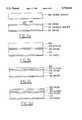
- FIGS. 3a-eillustrate in cross sectional elevation view a first preferred embodiment method of bonded wafer processing.
- Device wafer 302has the doping type and resistivity (e.g., N type and 20 ohm-cm resistivity) desired for eventual device fabrication and has only native oxide on its surfaces.
- Oxide 316will become the bottom oxide, so the oxide is grown to the desired bottom oxide thickenss; for example, 4 ⁇ m.
- Oxide 314provides stress compensation to restrain warpage. Place drop 305 of oxidizing aqueous solution of HNO 3 and H 2 O 2 on oxide 316; see FIG. 3a.
- Drop 305is 20% by volume a 67% HNO 3 solution and 80% by volume a 30% H 2 O 2 solution. Other mixtures also work. Drop 305 has a volume of about 0.05 cc which implies 4.0 microliters per square inch of wafer surface and theoretically will spread out to a layer with thickness (if uniform) of 6 ⁇ m on oxide 316. Note that drop 305 wets the surface of oxide 316. (Drop volume in the range of 4 to 10 microliters per square inch of wafer surface provides good bonding.) A buried layer in the final device structures will be formed as part of the bonding process, so device wafer 302 does not require an implant.
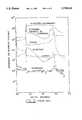
- FIG. 3hshows a SIMS (secondary ion mass spectroscopy) profile of the bonded wafer structure with nitrox apparent between the oxide (lefthand portion of FIG. 3h) and the silicon (center and righthand portion).
- FIG. 3ishows for comparison a SIMS profile of a bonded wafer made by the process of FIGS. 2a-c and with nitrogen implanted to the oxide-silicon interface.
- (f)Strip patterned oxide 326 with a wet etch. This etch also removes the remaining backside oxide 314 on the back of handle wafer 312. Then thermally grow oxide to a thickness of 4 ⁇ m to form isolation oxide 336 on the sides of islands 322, 323, . . . . This also forms 4 ⁇ m of oxide 338 on the island surfaces and 4 ⁇ m of backside oxide 346 on handle wafer 312. Next, deposit polysilicon 348 to fill the trenches. Lastly, planarize to remove the polysilicon except from the trenches. See FIG. 3f. Note that again the island surface oxide 338, bottom oxide 316, and backside oxide 346 all have about the same thickness (4 ⁇ m).
- FIG. 3gillustrates in magnified view a partially completed MOSFET in island 322 which would be just one of thousands of such devices in an integrated circuit fabricated on the bonded wafer.
- nitrox layer 315has a higher dielectric constant than bottom oxide layer 316.
- the dielectric constant of nitrideis about 7.9 and that of oxide is about 3.9.
- the second preferred embodiment method of bonded wafer processingfollows the steps of the first preferred embodiment method but augments or replaces the oxidizer of drop 305 by a silicon oxidizer such as aqueous HClO 4 .
- a silicon oxidizersuch as aqueous HClO 4 .
- the dropcould be 50% HNO 3 , 20% HClO 4 and 30% H 2 O 2 , or 100% HClO 4 .
- the same relatively low temperature bondingoccurs, and the chlorine ends up bonded in the silicon interface nitrox or oxide layer.
- the chlorineprovides an additional neutralizer for positive charge generated at the silicon interface due to radiation.
- perchlorateis similar to nitrate in that it both oxidizes silicon and provides positive charge neutralization.
- oxidizers of siliconsuch as CrO 3 , H 2 Cr 2 O 7 , . . . can be used for the relatively low temperature bonding. These oxidizers will leave Cr, . . . in the silicon interface bonded layer, and electronegative ones will aid radiation hardness by neutralizing positive charges.
- the third preferred embodiment methodfollows the steps of the first preferred embodiment method, but augments the oxidizer of drop 305 with radiation hardening dopants such as F, S, P, . . . which will remain (at least in part) at the silicon interface during bonding. That is, in addition to HNO 3 for relatively low temperature bonding, drop 305 contains dopants such as HF, H 2 S, POCl 3 , . . . which will generate electronegative dopants to neutralize radiation-generated positive charges as they arise.
- oxidizerssuch as dichromate plus electronegative dopants could provide both the low temperature bonding plus radiation hardening.
- a high temperature bonding (H 2 O 2 alone) with these dopantswould provide a doped oxide bonded layer which included radiation hardening.
- the fourth preferred embodiment methodfollows the steps of the first preferred embodiment method, but augments the oxidizer of drop 305 with buried layer dopants such as As, P, B, Sb, . . . which will diffuse into the bottoms of silicon islands 322, 323, . . . during bonding and form buried layers. That is, in addition to HNO 3 for relatively low temperature bonding, drop 305 contains dopants such as As 2 O 3 , POCl 3 , . . . which will generate the electrically active dopants such as As, P, B, Sb, in the device wafer during bonding. A portion of these dopants will diffuse to form buried layer 420 as illustrated in FIG.
- dopantssuch as As, P, B, Sb, in the device wafer during bonding.
- the doping concentrations of the buried layers in the silicondepends upon the quantity of dopants initially introduced into drop 305. For example, if drop 305 were 1% dopant, then the drop would provide a dose on the order of 10 18 dopant atoms per cm 2 of interface. Thus drop 305 can easily accomodate sufficient dopants even if only a small fraction of the dopants actually migrate out of the bonding zone during nitrox layer growth. Indeed, implantation of a buried layer typically uses an implant dose on the order of 10 16 dopant atoms/cm 2 . Recall that nitrox is a diffusion barrier for various dopants. Bonding at 1000° C. will help diffuse the dopants in the silicon and may be useful with thicker silicon islands.
- a high temperature bondinge.g., H 2 O 2 alone
- these dopantswould also yield buried layers, but the high bonding temperatures would diffuse the dopant much further into islands 322, 323, . . . and would not be useful for the case of very thin islands. For example, if islands 322, 323, . . . were only 1 ⁇ m thick, then a 2-6 hours bonding at 1150° C. would drive dopants throughout the islands.
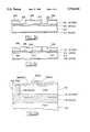
- FIGS. 5a-bshow modifications of the starting wafers for first preferred embodiment wafer bonding method.
- FIG. 5ahas device wafer 502 again with only native oxides, but handle wafer 512 has both 4000 A thick bottom thermal oxide 516 and 1000 A thick deposited nitrox layer 517.
- Nitrox layer 517has the composition Si w O x N y with x approximately equal to 0.6 and y approximately equal to 0.4 and may be formed by decomposition of silane with ammonia and oxygen.
- Drop 505is a solution of HNO 3 to provide oxidation of wafer 502 and bonding at 800-1000 C. The resulting bonded wafer illustrated in FIG.
- bonded nitrox layer 515of approximate thickness 500-800 A and composition Si w O x N y with x approximately equal to 0.8 and y approximately equal to 0.2.
- the stack of bonded nitrox layer 515 on deposited nitrox layer 517provides the advantages of (1) specifying the thickness and stoichiometry of buried nitrox 517 before deposition, (2) allowing a transition nitrox layer with different stoichiometry for matching stress and coefficients of thermal expansion, and (3) providing a barrier to contaminant diffusion if nitrox layer 517 is doped.
- dopantseither for buried layers in device wafer 502 or for radiation hardening the bonded nitrox 515 or both could be included in the oxidizer drop 505.
- nitrox 517could be replaced with deposited and steam densified aluminum oxide (pseudo-sapphire) also of thickness about 1000 A.
- the bonded waferswould then be separated by a stack of dielectrics: nitrox 515 on aluminum oxide 517 which is on thermal oxide 516.
- This inclusion of nitrox 515 on top of aluminum oxide 517has the advantages of (1) increased radiation hardness of pseudo-sapphire layer, (2) the presence of a diffusion barrier (nitrox 515) to keep the aluminum in 517 from diffusing into the device silicon, and (3) a more closely matched thermal coefficient of expansion of nitrox 517 to the bonding nitrox layer and silicon device wafer than aluminum oxide 517.
- FIG. 6illustrates a variation of deposited nitrox/aluminum oxide layer 517 of FIG. 5a where additional silicon to aid the bonding has been included.
- handle wafer 612has 4000 A thick bottom oxide 616, 500 A thick deposited nitrox or aluminum oxide 617, plus 300 A thick polysilicon layer 618.
- drop 605contains an oxidizing solution such as HNO 3 plus H 2 O 2 . Bonding liquid oxidizes polysilicon 618 to nitrox in a manner similar to the oxidation of the surface portion of wafer 602. In effect, the nitrox can form at both surfaces of the oxidizing liquid (drop 605 squeezed between the wafers).
- Drop 605 when uniformly spread over wafers 602 and 612will form a layer about 6 ⁇ m thick and provide sufficient oxidizers to totally consume polysilicon layer 618 plus at least 300-500 A of device wafer 602.
- the advantage of polysilicon layer 618is that (1) it supplied a source of silicon for the bonding liquid to react with to form nitrox in the bonding zone without consuming substantial amounts of device wafer 602 (which might be doped), (2) it can be polished to provide a smooth surface for bonding if the underlying deposited dielectrics are rough, and (3) it can be thermally oxidized before bonding to provide a layer of silicon oxide between the deposited dielectric, the bonding nitrox and device wafer 602.
- FIGS. 7a-billustrate in cross sectional elevation views another preferred embodiment wafer bonding method; this method employs dielectric layers on both wafers and supplies the silicon for bonding as part of the bond process as follows.
- Nitrox layers 717 and 707have the composition Si w O x N y with x approximately equal to 0.6 and y approximately equal to 0.4 plus unreacted silane (SiH 4 ). (Unreacted silane in the nitrox can be detected by infrared spectroscopy).
- Drop 705is 50% by volume a 67% HNO 3 solution and 50% by volume a 30% H 2 O 2 solution.
- Drop 705has a volume of about 0.05 cc which implies 4.0 microliters per square inch of wafer surface and theoretically will spread out to a layer with thickness (if uniform) of 6 ⁇ m on oxide 716. Note that drop 705 wets the surface of nitrox 716. (Drop volume in the range of 4 to 10 microliters per square inch of wafer surface provides good bonding.)
- the silaneforms both silicon-oxygen and silicon-nitrogen bonds; and the water primarily evaporates.
- Bonded zone nitrox 715has a thickness of roughly 500-800 ⁇ ⁇ m and average values of x and y of roughly 0.8 and 0.2, respectively.
- increasing the ratio of HNO 3 to H 2 O 2will increase x and decrease y, and conversely for a decrease in the ratio.
- FIG. 8illustrates the starting wafers for a further preferred embodiment method of wafer bonding.
- Device wafer 802has thermal oxide layer 806 of thickness 0.1-0.4 ⁇ m and polysilicon layer 808 of thickness 500 ⁇ .
- handle wafer 812has deposited or thermally grown dielectric layer 816 of thickness 1 ⁇ m and may have polysilicon layer 818 of thickness 500 ⁇ .
- Drop 806contains silicon oxidizer HNO 3 .
- the quantity of nitrate in drop 805matches the quantity of polysilicon in layers 808 and 818 for stoichiometric nitrox, as follows. 1000 ⁇ total thickness of polysilicon provides about 3 ⁇ 10 17 atoms of silicon per cm 2 . With HNO 3 the only oxidizer, the reaction generates nitrox 815 through the reaction:
- oxides 806 and 816could be replaced in part by nitrides which would be barriers to oxidation of the underlying wafer silicon, but the bonding would still proceed using silicon from polysilicon 806 and/or 816.
- Controlling the bonding liquid and overall dielectric thicknessespromotes unstressed chemical bonding gradients between the deposited dielectric(s) and the reacted dielectric. Maintaining minimum film thicknesses is critical in hekping to eliminate localized stress caused by dissimilar dielectric materials. It is imperative that the bonding liquid provide the correct elements and oxidative potential to not etch the deposited dielectric, as well as create reacted layers with compatible coefficients of thermal expansion. This will allow a chemical bonding transition from the deposited dielectric(s) through the generated dielectric into the silicon. This is accomplished by controlling the elements in the bonding liquid, molar concentration ratios, solution volumes and bonding temperature.
- Radiation hardened buried insulators for increased radiation tolerance in military and space IC applications without the characteristics of implanted hardeningsilicon crystal damage from implanting, conducting "pipes" in the buried dielectric which can result from surface particulates preventing the correct implant dosage from reaching the buried layer in the silicon to form a stoichiometric dielectric.
- Tight buried layersdue to no implant tailing, relatively low wafer bonding temperature, and no defect annealing.
Landscapes
- Engineering & Computer Science (AREA)
- Physics & Mathematics (AREA)
- Microelectronics & Electronic Packaging (AREA)
- General Physics & Mathematics (AREA)
- Manufacturing & Machinery (AREA)
- Computer Hardware Design (AREA)
- Condensed Matter Physics & Semiconductors (AREA)
- Power Engineering (AREA)
- High Energy & Nuclear Physics (AREA)
- Health & Medical Sciences (AREA)
- Toxicology (AREA)
- Element Separation (AREA)
- Formation Of Insulating Films (AREA)
Abstract
Description
Si+HNO.sub.3 +H.sub.2 O.sub.2 →Si.sub.w O.sub.x N.sub.y +H.sub.2 O+O.sub.2
4Si+2HNO.sub.3 →Si.sub.4 O.sub.5 N.sub.2 +H.sub.2 O
Claims (11)
Priority Applications (1)
| Application Number | Priority Date | Filing Date | Title |
|---|---|---|---|
| US08/573,551US5728624A (en) | 1992-07-28 | 1995-12-15 | Bonded wafer processing |
Applications Claiming Priority (3)
| Application Number | Priority Date | Filing Date | Title |
|---|---|---|---|
| US07/921,197US5362667A (en) | 1992-07-28 | 1992-07-28 | Bonded wafer processing |
| US08/287,773US5517047A (en) | 1992-07-28 | 1994-08-09 | Bonded wafer processing |
| US08/573,551US5728624A (en) | 1992-07-28 | 1995-12-15 | Bonded wafer processing |
Related Parent Applications (1)
| Application Number | Title | Priority Date | Filing Date |
|---|---|---|---|
| US08/287,773DivisionUS5517047A (en) | 1992-07-28 | 1994-08-09 | Bonded wafer processing |
Publications (1)
| Publication Number | Publication Date |
|---|---|
| US5728624Atrue US5728624A (en) | 1998-03-17 |
Family
ID=25445072
Family Applications (3)
| Application Number | Title | Priority Date | Filing Date |
|---|---|---|---|
| US07/921,197Expired - LifetimeUS5362667A (en) | 1990-02-07 | 1992-07-28 | Bonded wafer processing |
| US08/287,773Expired - LifetimeUS5517047A (en) | 1992-07-28 | 1994-08-09 | Bonded wafer processing |
| US08/573,551Expired - LifetimeUS5728624A (en) | 1992-07-28 | 1995-12-15 | Bonded wafer processing |
Family Applications Before (2)
| Application Number | Title | Priority Date | Filing Date |
|---|---|---|---|
| US07/921,197Expired - LifetimeUS5362667A (en) | 1990-02-07 | 1992-07-28 | Bonded wafer processing |
| US08/287,773Expired - LifetimeUS5517047A (en) | 1992-07-28 | 1994-08-09 | Bonded wafer processing |
Country Status (1)
| Country | Link |
|---|---|
| US (3) | US5362667A (en) |
Cited By (22)
| Publication number | Priority date | Publication date | Assignee | Title |
|---|---|---|---|---|
| US5933750A (en)* | 1998-04-03 | 1999-08-03 | Motorola, Inc. | Method of fabricating a semiconductor device with a thinned substrate |
| US6004865A (en)* | 1993-09-06 | 1999-12-21 | Hitachi, Ltd. | Method of fabricating multi-layered structure having single crystalline semiconductor film formed on insulator |
| US6383849B1 (en)* | 1996-06-29 | 2002-05-07 | Hyundai Electronics Industries Co., Ltd. | Semiconductor device and method for fabricating the same |
| US20020096491A1 (en)* | 2000-08-25 | 2002-07-25 | Tandy William D. | Method and apparatus for marking a bare semiconductor die |
| US6455398B1 (en)* | 1999-07-16 | 2002-09-24 | Massachusetts Institute Of Technology | Silicon on III-V semiconductor bonding for monolithic optoelectronic integration |
| US20030113981A1 (en)* | 2001-10-30 | 2003-06-19 | Stmicroelectronics S.R.I. | Process for manufacturing a semiconductor wafer integrating electronic devices and a structure for electromagnetic decoupling |
| US20030162368A1 (en)* | 2002-02-25 | 2003-08-28 | Connell Michael E. | Wafer back side coating to balance stress from passivation layer on front of wafer and be used as a die attach adhesive |
| US6707106B1 (en) | 2002-10-18 | 2004-03-16 | Advanced Micro Devices, Inc. | Semiconductor device with tensile strain silicon introduced by compressive material in a buried oxide layer |
| US6743662B2 (en)* | 2002-07-01 | 2004-06-01 | Honeywell International, Inc. | Silicon-on-insulator wafer for RF integrated circuit |
| US20040161905A1 (en)* | 1999-06-30 | 2004-08-19 | Intersil Americas Inc. | Integrated circuit having a device wafer with a diffused doped backside layer |
| US20050011669A1 (en)* | 2002-12-17 | 2005-01-20 | Finisar Corporation | Low temperature bonding of multilayer substrates |
| US20050233543A1 (en)* | 2004-04-20 | 2005-10-20 | Agency For Science, Technology And Research | Method of fabricating microelectromechanical system structures |
| US20050285172A1 (en)* | 2002-12-17 | 2005-12-29 | Freeman William R | Methods of forming vias in multilayer substrates |
| US20060102988A1 (en)* | 2004-11-12 | 2006-05-18 | Tolchinsky Peter G | Method for manufacturing a silicon-on-Insulator (SOI) wafer with an etch stop layer |
| US20060220028A1 (en)* | 2005-03-03 | 2006-10-05 | Shaheen Mohamad A | Silicon on diamond-like carbon devices |
| US7192841B2 (en) | 2002-04-30 | 2007-03-20 | Agency For Science, Technology And Research | Method of wafer/substrate bonding |
| US20070063217A1 (en)* | 2005-08-22 | 2007-03-22 | Icemos Technology Corporation | Bonded-wafer Superjunction Semiconductor Device |
| CN100355034C (en)* | 2004-11-08 | 2007-12-12 | 北京邮电大学 | Wafer bonding surface processing agent and wafer bonding method |
| US20100065946A1 (en)* | 2008-03-28 | 2010-03-18 | Icemos Technology Ltd. | Bonded Wafer Substrate for Use in MEMS Structures |
| US20190344533A1 (en)* | 2003-05-19 | 2019-11-14 | Invensas Bonding Technologies, Inc. | Method of room temperature covalent bonding |
| TWI870332B (en)* | 2024-08-26 | 2025-01-11 | 聯華電子股份有限公司 | Method for manufacturing semiconductor bonding structure |
| US12424584B2 (en) | 2020-10-29 | 2025-09-23 | Adeia Semiconductor Bonding Technologies Inc. | Direct bonding methods and structures |
Families Citing this family (58)
| Publication number | Priority date | Publication date | Assignee | Title |
|---|---|---|---|---|
| US5849627A (en)* | 1990-02-07 | 1998-12-15 | Harris Corporation | Bonded wafer processing with oxidative bonding |
| US5362667A (en)* | 1992-07-28 | 1994-11-08 | Harris Corporation | Bonded wafer processing |
| US6909146B1 (en) | 1992-02-12 | 2005-06-21 | Intersil Corporation | Bonded wafer with metal silicidation |
| US5272104A (en)* | 1993-03-11 | 1993-12-21 | Harris Corporation | Bonded wafer process incorporating diamond insulator |
| US5689136A (en) | 1993-08-04 | 1997-11-18 | Hitachi, Ltd. | Semiconductor device and fabrication method |
| JPH07153808A (en)* | 1993-09-24 | 1995-06-16 | Shin Etsu Handotai Co Ltd | Boron estimation method of bonding interface of stacked substrate |
| KR950021600A (en)* | 1993-12-09 | 1995-07-26 | 가나이 쯔또무 | Semiconductor integrated circuit device and manufacturing method thereof |
| US5526768A (en)* | 1994-02-03 | 1996-06-18 | Harris Corporation | Method for providing a silicon and diamond substrate having a carbon to silicon transition layer and apparatus thereof |
| JP2895743B2 (en)* | 1994-03-25 | 1999-05-24 | 信越半導体株式会社 | Method for manufacturing SOI substrate |
| US5729038A (en)* | 1995-12-15 | 1998-03-17 | Harris Corporation | Silicon-glass bonded wafers |
| JP3542376B2 (en)* | 1994-04-08 | 2004-07-14 | キヤノン株式会社 | Manufacturing method of semiconductor substrate |
| WO1996020497A1 (en)* | 1994-12-23 | 1996-07-04 | Philips Electronics N.V. | Method of manufacturing semiconductor devices with semiconductor elements formed in a layer of semiconductor material glued on a support wafer |
| US5494849A (en)* | 1995-03-23 | 1996-02-27 | Si Bond L.L.C. | Single-etch stop process for the manufacture of silicon-on-insulator substrates |
| US5789793A (en)* | 1995-07-31 | 1998-08-04 | Kurtz; Anthony D. | Dielectrically isolated well structures |
| US5985728A (en)* | 1995-09-01 | 1999-11-16 | Elantec Semiconductor, Inc. | Silicon on insulator process with recovery of a device layer from an etch stop layer |
| DE19538005A1 (en)* | 1995-10-12 | 1997-04-17 | Fraunhofer Ges Forschung | Method of creating trench isolation in a substrate |
| KR0165467B1 (en)* | 1995-10-31 | 1999-02-01 | 김광호 | Wafer Debonder and Wafer Debonding Method Using the Same |
| KR970052024A (en)* | 1995-12-30 | 1997-07-29 | 김주용 | SOH eye substrate manufacturing method |
| JP3378135B2 (en)* | 1996-02-02 | 2003-02-17 | 三菱電機株式会社 | Semiconductor device and manufacturing method thereof |
| JPH09298195A (en)* | 1996-05-08 | 1997-11-18 | Mitsubishi Electric Corp | Semiconductor device and manufacturing method thereof |
| JP3266041B2 (en)* | 1996-05-22 | 2002-03-18 | 株式会社島津製作所 | Member joining method and optical measuring device manufactured by this method |
| KR100233286B1 (en)* | 1996-06-29 | 1999-12-01 | 김영환 | Semiconductor device and manufacturing method thereof |
| KR100207485B1 (en)* | 1996-07-23 | 1999-07-15 | 윤종용 | Capacitor Manufacturing Method of Semiconductor Device |
| US5914280A (en) | 1996-12-23 | 1999-06-22 | Harris Corporation | Deep trench etch on bonded silicon wafer |
| US6310385B1 (en)* | 1997-01-16 | 2001-10-30 | International Rectifier Corp. | High band gap layer to isolate wells in high voltage power integrated circuits |
| WO1999017357A1 (en)* | 1997-09-30 | 1999-04-08 | Infineon Technologies Ag | Product comprised of a silicon-containing functional layer and an insulating layer of silicon dioxide, and production |
| US5982006A (en)* | 1997-12-09 | 1999-11-09 | Texas Instruments Incorporated | Active silicon-on-insulator region having a buried insulation layer with tapered edge |
| US6133610A (en) | 1998-01-20 | 2000-10-17 | International Business Machines Corporation | Silicon-on-insulator chip having an isolation barrier for reliability and process of manufacture |
| US6492684B2 (en) | 1998-01-20 | 2002-12-10 | International Business Machines Corporation | Silicon-on-insulator chip having an isolation barrier for reliability |
| KR100331844B1 (en)* | 1998-02-12 | 2002-05-10 | 박종섭 | Complementary metal oxide semiconductor device |
| DE19821999A1 (en)* | 1998-05-15 | 1999-11-18 | Siemens Ag | Silicon-On-Isolator semiconductor arrangement |
| US6034403A (en)* | 1998-06-25 | 2000-03-07 | Acer Semiconductor Manufacturing, Inc. | High density flat cell mask ROM |
| US6051865A (en)* | 1998-11-09 | 2000-04-18 | Advanced Micro Devices, Inc. | Transistor having a barrier layer below a high permittivity gate dielectric |
| FR2789518B1 (en)* | 1999-02-10 | 2003-06-20 | Commissariat Energie Atomique | MULTILAYER STRUCTURE WITH INTERNAL CONTROLLED STRESSES AND METHOD FOR PRODUCING SUCH A STRUCTURE |
| US6268630B1 (en)* | 1999-03-16 | 2001-07-31 | Sandia Corporation | Silicon-on-insulator field effect transistor with improved body ties for rad-hard applications |
| US6461899B1 (en)* | 1999-04-30 | 2002-10-08 | Semiconductor Energy Laboratory, Co., Ltd. | Oxynitride laminate “blocking layer” for thin film semiconductor devices |
| EP1161769A1 (en)* | 1999-12-24 | 2001-12-12 | Koninklijke Philips Electronics N.V. | Method of manufacturing a semiconductor device comprising semiconductor elements formed in a top layer of a silicon wafer situated on a buried insulating layer |
| EP2270875B1 (en)* | 2000-04-26 | 2018-01-10 | OSRAM Opto Semiconductors GmbH | Sermiconductor light emitting device and method of manufacturing the same |
| DE10051465A1 (en) | 2000-10-17 | 2002-05-02 | Osram Opto Semiconductors Gmbh | Method for producing a GaN-based semiconductor component |
| CN1252837C (en)* | 2000-04-26 | 2006-04-19 | 奥斯兰姆奥普托半导体股份有限两合公司 | Light emitting diode chip on GaN substrate and method of manufacturing light emitting diode element using light emitting diode chip on GaN substrate |
| TWI289944B (en)* | 2000-05-26 | 2007-11-11 | Osram Opto Semiconductors Gmbh | Light-emitting-diode-element with a light-emitting-diode-chip |
| DE10041748A1 (en)* | 2000-08-27 | 2002-03-14 | Infineon Technologies Ag | SOI substrate and semiconductor circuit formed therein and associated manufacturing processes |
| US6576957B2 (en)* | 2000-12-31 | 2003-06-10 | Texas Instruments Incorporated | Etch-stopped SOI back-gate contact |
| TW564471B (en)* | 2001-07-16 | 2003-12-01 | Semiconductor Energy Lab | Semiconductor device and peeling off method and method of manufacturing semiconductor device |
| EP1425110B1 (en)* | 2001-07-18 | 2014-09-03 | The Regents of the University of Colorado | A method of depositing an inorganic film on an organic polymer |
| EP1440463A2 (en)* | 2001-10-29 | 2004-07-28 | Analog Devices, Incorporated | Method for cleaning silicon wafers surfaces before bonding |
| KR100476901B1 (en)* | 2002-05-22 | 2005-03-17 | 삼성전자주식회사 | Method of forming SOI(Silicon-On-Insulator) semiconductor substrate |
| US20040126993A1 (en)* | 2002-12-30 | 2004-07-01 | Chan Kevin K. | Low temperature fusion bonding with high surface energy using a wet chemical treatment |
| US6949451B2 (en)* | 2003-03-10 | 2005-09-27 | Taiwan Semiconductor Manufacturing Company, Ltd. | SOI chip with recess-resistant buried insulator and method of manufacturing the same |
| FR2858461B1 (en)* | 2003-07-30 | 2005-11-04 | Soitec Silicon On Insulator | IMPLEMENTING A STRUCTURE COMPRISING A PROTECTIVE LAYER AGAINST CHEMICAL TREATMENTS |
| WO2005027204A1 (en)* | 2003-09-08 | 2005-03-24 | Sumco Corporation | Bonded wafer and its manufacturing method |
| US7075103B2 (en)* | 2003-12-19 | 2006-07-11 | General Electric Company | Multilayer device and method of making |
| JP2006080314A (en)* | 2004-09-09 | 2006-03-23 | Canon Inc | Manufacturing method of bonded substrate |
| JP5688203B2 (en)* | 2007-11-01 | 2015-03-25 | 株式会社半導体エネルギー研究所 | Method for manufacturing semiconductor substrate |
| US8119490B2 (en)* | 2008-02-04 | 2012-02-21 | Semiconductor Energy Laboratory Co., Ltd. | Method for manufacturing SOI substrate |
| JP5365057B2 (en)* | 2008-04-11 | 2013-12-11 | 株式会社Sumco | Manufacturing method of bonded wafer |
| JP5700617B2 (en) | 2008-07-08 | 2015-04-15 | 株式会社半導体エネルギー研究所 | Method for manufacturing SOI substrate |
| JP2010135538A (en)* | 2008-12-04 | 2010-06-17 | Sumco Corp | Method of manufacturing bonded wafer |
Citations (10)
| Publication number | Priority date | Publication date | Assignee | Title |
|---|---|---|---|---|
| JPS5658269A (en)* | 1979-10-17 | 1981-05-21 | Seiko Epson Corp | Mos type semiconductor device |
| US4878957A (en)* | 1988-03-31 | 1989-11-07 | Kabushiki Kaisha Toshiba | Dielectrically isolated semiconductor substrate |
| JPH0218961A (en)* | 1988-07-07 | 1990-01-23 | Seiko Epson Corp | Manufacturing method of semiconductor substrate |
| US5187636A (en)* | 1991-07-18 | 1993-02-16 | Rohm Co., Ltd. | Dielectric device |
| US5236546A (en)* | 1987-01-26 | 1993-08-17 | Canon Kabushiki Kaisha | Process for producing crystal article |
| US5241211A (en)* | 1989-12-20 | 1993-08-31 | Nec Corporation | Semiconductor device |
| US5294821A (en)* | 1990-10-09 | 1994-03-15 | Seiko Epson Corporation | Thin-film SOI semiconductor device having heavily doped diffusion regions beneath the channels of transistors |
| US5322589A (en)* | 1989-02-09 | 1994-06-21 | Fujitsu Limited | Process and apparatus for recrystallization of semiconductor layer |
| US5362667A (en)* | 1992-07-28 | 1994-11-08 | Harris Corporation | Bonded wafer processing |
| US5387555A (en)* | 1992-09-03 | 1995-02-07 | Harris Corporation | Bonded wafer processing with metal silicidation |
Family Cites Families (1)
| Publication number | Priority date | Publication date | Assignee | Title |
|---|---|---|---|---|
| JP2822656B2 (en)* | 1990-10-17 | 1998-11-11 | 株式会社デンソー | Semiconductor device and manufacturing method thereof |
- 1992
- 1992-07-28USUS07/921,197patent/US5362667A/ennot_activeExpired - Lifetime
- 1994
- 1994-08-09USUS08/287,773patent/US5517047A/ennot_activeExpired - Lifetime
- 1995
- 1995-12-15USUS08/573,551patent/US5728624A/ennot_activeExpired - Lifetime
Patent Citations (10)
| Publication number | Priority date | Publication date | Assignee | Title |
|---|---|---|---|---|
| JPS5658269A (en)* | 1979-10-17 | 1981-05-21 | Seiko Epson Corp | Mos type semiconductor device |
| US5236546A (en)* | 1987-01-26 | 1993-08-17 | Canon Kabushiki Kaisha | Process for producing crystal article |
| US4878957A (en)* | 1988-03-31 | 1989-11-07 | Kabushiki Kaisha Toshiba | Dielectrically isolated semiconductor substrate |
| JPH0218961A (en)* | 1988-07-07 | 1990-01-23 | Seiko Epson Corp | Manufacturing method of semiconductor substrate |
| US5322589A (en)* | 1989-02-09 | 1994-06-21 | Fujitsu Limited | Process and apparatus for recrystallization of semiconductor layer |
| US5241211A (en)* | 1989-12-20 | 1993-08-31 | Nec Corporation | Semiconductor device |
| US5294821A (en)* | 1990-10-09 | 1994-03-15 | Seiko Epson Corporation | Thin-film SOI semiconductor device having heavily doped diffusion regions beneath the channels of transistors |
| US5187636A (en)* | 1991-07-18 | 1993-02-16 | Rohm Co., Ltd. | Dielectric device |
| US5362667A (en)* | 1992-07-28 | 1994-11-08 | Harris Corporation | Bonded wafer processing |
| US5387555A (en)* | 1992-09-03 | 1995-02-07 | Harris Corporation | Bonded wafer processing with metal silicidation |
Non-Patent Citations (4)
| Title |
|---|
| Haisma, et al., "Silicon-on-Insulator Wafer Bonding-Wafer Thinning Technological Evaluations", Japanese Journal Appl. Phys., vol. 28, No. 8, 1989, Japan. |
| Haisma, et al., Silicon on Insulator Wafer Bonding Wafer Thinning Technological Evaluations , Japanese Journal Appl. Phys. , vol. 28, No. 8, 1989, Japan.* |
| P.J. Burkhardt, "Composite Silicon Dioxide-Silicon Oxynitride Insulating Layer", IBM Technical Disclosure Bulletin, vol. 13, No. 1, Jun. 1970. |
| P.J. Burkhardt, Composite Silicon Dioxide Silicon Oxynitride Insulating Layer , IBM Technical Disclosure Bulletin , vol. 13, No. 1, Jun. 1970.* |
Cited By (52)
| Publication number | Priority date | Publication date | Assignee | Title |
|---|---|---|---|---|
| US6004865A (en)* | 1993-09-06 | 1999-12-21 | Hitachi, Ltd. | Method of fabricating multi-layered structure having single crystalline semiconductor film formed on insulator |
| US6383849B1 (en)* | 1996-06-29 | 2002-05-07 | Hyundai Electronics Industries Co., Ltd. | Semiconductor device and method for fabricating the same |
| US6635927B2 (en)* | 1996-06-29 | 2003-10-21 | Hyundai Electronics Industries Co., Ltd. | Semiconductor device and method for fabricating the same |
| US5933750A (en)* | 1998-04-03 | 1999-08-03 | Motorola, Inc. | Method of fabricating a semiconductor device with a thinned substrate |
| US20080026595A1 (en)* | 1999-06-30 | 2008-01-31 | Intersil Americas Inc. | Method of forming an integrated circuit having a device wafer with a diffused doped backside layer |
| US7285475B2 (en) | 1999-06-30 | 2007-10-23 | Intersil Americas Inc. | Integrated circuit having a device wafer with a diffused doped backside layer |
| US6946364B2 (en) | 1999-06-30 | 2005-09-20 | Intersil Americas Inc. | Integrated circuit having a device wafer with a diffused doped backside layer |
| EP1065706A3 (en)* | 1999-06-30 | 2004-10-27 | Intersil Corporation | Method for making a diffused back-side layer on a bonded-wafer with a thick bond oxide |
| US20040161905A1 (en)* | 1999-06-30 | 2004-08-19 | Intersil Americas Inc. | Integrated circuit having a device wafer with a diffused doped backside layer |
| US20060009007A1 (en)* | 1999-06-30 | 2006-01-12 | Intersil Americas Inc. | Integrated circuit having a device wafer with a diffused doped backside layer |
| US7605052B2 (en) | 1999-06-30 | 2009-10-20 | Intersil Corporation | Method of forming an integrated circuit having a device wafer with a diffused doped backside layer |
| US6455398B1 (en)* | 1999-07-16 | 2002-09-24 | Massachusetts Institute Of Technology | Silicon on III-V semiconductor bonding for monolithic optoelectronic integration |
| US20040161876A1 (en)* | 2000-08-25 | 2004-08-19 | Tandy William D. | Methods for marking a bare semiconductor die |
| US20060079011A1 (en)* | 2000-08-25 | 2006-04-13 | Tandy William D | Methods for marking a bare semiconductor die |
| US7094618B2 (en) | 2000-08-25 | 2006-08-22 | Micron Technology, Inc. | Methods for marking a packaged semiconductor die including applying tape and subsequently marking the tape |
| US20020096491A1 (en)* | 2000-08-25 | 2002-07-25 | Tandy William D. | Method and apparatus for marking a bare semiconductor die |
| US7238543B2 (en) | 2000-08-25 | 2007-07-03 | Micron Technology, Inc. | Methods for marking a bare semiconductor die including applying a tape having energy-markable properties |
| US20030113981A1 (en)* | 2001-10-30 | 2003-06-19 | Stmicroelectronics S.R.I. | Process for manufacturing a semiconductor wafer integrating electronic devices and a structure for electromagnetic decoupling |
| US6869856B2 (en)* | 2001-10-30 | 2005-03-22 | Stmicroelectronics S.R.L. | Process for manufacturing a semiconductor wafer integrating electronic devices including a structure for electromagnetic decoupling |
| US20040104491A1 (en)* | 2002-02-25 | 2004-06-03 | Connell Michael E. | Wafer back side coating to balance stress from passivation layer on front of wafer and be used as a die attach adhesive |
| US7727785B2 (en) | 2002-02-25 | 2010-06-01 | Micron Technology, Inc. | Wafer back side coating to balance stress from passivation layer on front of wafer and be used as die attach adhesive |
| US20030162368A1 (en)* | 2002-02-25 | 2003-08-28 | Connell Michael E. | Wafer back side coating to balance stress from passivation layer on front of wafer and be used as a die attach adhesive |
| US7169685B2 (en) | 2002-02-25 | 2007-01-30 | Micron Technology, Inc. | Wafer back side coating to balance stress from passivation layer on front of wafer and be used as die attach adhesive |
| US7192841B2 (en) | 2002-04-30 | 2007-03-20 | Agency For Science, Technology And Research | Method of wafer/substrate bonding |
| US20040159908A1 (en)* | 2002-07-01 | 2004-08-19 | Fathimulla Mohammed A. | Silicon-on-insulator wafer for RF integrated circuit |
| US6743662B2 (en)* | 2002-07-01 | 2004-06-01 | Honeywell International, Inc. | Silicon-on-insulator wafer for RF integrated circuit |
| US6707106B1 (en) | 2002-10-18 | 2004-03-16 | Advanced Micro Devices, Inc. | Semiconductor device with tensile strain silicon introduced by compressive material in a buried oxide layer |
| US7259466B2 (en) | 2002-12-17 | 2007-08-21 | Finisar Corporation | Low temperature bonding of multilayer substrates |
| US20050011669A1 (en)* | 2002-12-17 | 2005-01-20 | Finisar Corporation | Low temperature bonding of multilayer substrates |
| US20050285172A1 (en)* | 2002-12-17 | 2005-12-29 | Freeman William R | Methods of forming vias in multilayer substrates |
| US7361593B2 (en) | 2002-12-17 | 2008-04-22 | Finisar Corporation | Methods of forming vias in multilayer substrates |
| US11760059B2 (en) | 2003-05-19 | 2023-09-19 | Adeia Semiconductor Bonding Technologies Inc. | Method of room temperature covalent bonding |
| US20190344533A1 (en)* | 2003-05-19 | 2019-11-14 | Invensas Bonding Technologies, Inc. | Method of room temperature covalent bonding |
| US7153759B2 (en) | 2004-04-20 | 2006-12-26 | Agency For Science Technology And Research | Method of fabricating microelectromechanical system structures |
| US20070105342A1 (en)* | 2004-04-20 | 2007-05-10 | Jun Wei | Method of fabricating microelectromechanical system structures |
| US20050233543A1 (en)* | 2004-04-20 | 2005-10-20 | Agency For Science, Technology And Research | Method of fabricating microelectromechanical system structures |
| US7405466B2 (en) | 2004-04-20 | 2008-07-29 | Agency For Science, Technology And Research | Method of fabricating microelectromechanical system structures |
| CN100355034C (en)* | 2004-11-08 | 2007-12-12 | 北京邮电大学 | Wafer bonding surface processing agent and wafer bonding method |
| US7473614B2 (en)* | 2004-11-12 | 2009-01-06 | Intel Corporation | Method for manufacturing a silicon-on-insulator (SOI) wafer with an etch stop layer |
| US20060102988A1 (en)* | 2004-11-12 | 2006-05-18 | Tolchinsky Peter G | Method for manufacturing a silicon-on-Insulator (SOI) wafer with an etch stop layer |
| US20090096025A1 (en)* | 2004-11-12 | 2009-04-16 | Tolchinsky Peter G | Method for manufacturing a silicon-on-insulator (SOI) wafer with an etch stop layer |
| US20060220028A1 (en)* | 2005-03-03 | 2006-10-05 | Shaheen Mohamad A | Silicon on diamond-like carbon devices |
| US7355247B2 (en)* | 2005-03-03 | 2008-04-08 | Intel Corporation | Silicon on diamond-like carbon devices |
| US7579667B2 (en) | 2005-08-22 | 2009-08-25 | Icemos Technology Ltd. | Bonded-wafer superjunction semiconductor device |
| US7446018B2 (en) | 2005-08-22 | 2008-11-04 | Icemos Technology Corporation | Bonded-wafer superjunction semiconductor device |
| US20080315247A1 (en)* | 2005-08-22 | 2008-12-25 | Icemos Technology Corporation | Bonded-wafer superjunction semiconductor device |
| US20070063217A1 (en)* | 2005-08-22 | 2007-03-22 | Icemos Technology Corporation | Bonded-wafer Superjunction Semiconductor Device |
| US20100065946A1 (en)* | 2008-03-28 | 2010-03-18 | Icemos Technology Ltd. | Bonded Wafer Substrate for Use in MEMS Structures |
| US8030133B2 (en) | 2008-03-28 | 2011-10-04 | Icemos Technology Ltd. | Method of fabricating a bonded wafer substrate for use in MEMS structures |
| US8253243B2 (en) | 2008-03-28 | 2012-08-28 | Icemos Technology Ltd. | Bonded wafer substrate utilizing roughened surfaces for use in MEMS structures |
| US12424584B2 (en) | 2020-10-29 | 2025-09-23 | Adeia Semiconductor Bonding Technologies Inc. | Direct bonding methods and structures |
| TWI870332B (en)* | 2024-08-26 | 2025-01-11 | 聯華電子股份有限公司 | Method for manufacturing semiconductor bonding structure |
Also Published As
| Publication number | Publication date |
|---|---|
| US5517047A (en) | 1996-05-14 |
| US5362667A (en) | 1994-11-08 |
Similar Documents
| Publication | Publication Date | Title |
|---|---|---|
| US5728624A (en) | Bonded wafer processing | |
| US5849627A (en) | Bonded wafer processing with oxidative bonding | |
| US5387555A (en) | Bonded wafer processing with metal silicidation | |
| US4601779A (en) | Method of producing a thin silicon-on-insulator layer | |
| JP3037934B2 (en) | Improved smart cut process for the production of semiconductor material thin films | |
| KR100985932B1 (en) | Method for manufacturing silicon germanium-on-insulator substrates and germanium-on-insulator substrates | |
| US5780311A (en) | bonded wafer processing | |
| US4897362A (en) | Double epitaxial method of fabricating semiconductor devices on bonded wafers | |
| US4789560A (en) | Diffusion stop method for forming silicon oxide during the fabrication of IC devices | |
| US4875086A (en) | Silicon-on-insulator integrated circuits and method | |
| WO1986002777A1 (en) | Process for forming isolation regions in a semiconductor substrate | |
| JP2003347525A (en) | Formation method of soi semiconductor substrate and soi semiconductor substrate formed thereby | |
| US6909146B1 (en) | Bonded wafer with metal silicidation | |
| EP0701286B1 (en) | Silicon on insulating substrate and manufacturing method for same | |
| US6127244A (en) | Method of manufacturing semiconductor device | |
| US5897362A (en) | Bonding silicon wafers | |
| JPH0982956A (en) | Semiconductor device and manufacturing method thereof | |
| US5525535A (en) | Method for making doped well and field regions on semiconductor substrates for field effect transistors using liquid phase deposition of oxides | |
| US20070128742A1 (en) | Method of forming silicon-on-insulator (soi) semiconductor substrate and soi semiconductor substrate formed thereby | |
| US20050170608A1 (en) | Semiconductor device and, manufacturing method thereof | |
| WO1994023444A2 (en) | Bonded wafer processing with oxidative bonding | |
| US6602759B2 (en) | Shallow trench isolation for thin silicon/silicon-on-insulator substrates by utilizing polysilicon | |
| US6737337B1 (en) | Method of preventing dopant depletion in surface semiconductor layer of semiconductor-on-insulator (SOI) device | |
| JPH10189609A (en) | Semiconductor device and manufacturing method thereof | |
| JPS6155250B2 (en) |
Legal Events
| Date | Code | Title | Description |
|---|---|---|---|
| STCF | Information on status: patent grant | Free format text:PATENTED CASE | |
| AS | Assignment | Owner name:INTERSIL CORPORATION, FLORIDA Free format text:ASSIGNMENT OF ASSIGNORS INTEREST;ASSIGNOR:HARRIS CORPORATION;REEL/FRAME:010247/0043 Effective date:19990813 | |
| AS | Assignment | Owner name:CREDIT SUISSE FIRST BOSTON, AS COLLATERAL AGENT, N Free format text:SECURITY INTEREST;ASSIGNOR:INTERSIL CORPORATION;REEL/FRAME:010351/0410 Effective date:19990813 | |
| FEPP | Fee payment procedure | Free format text:PAYOR NUMBER ASSIGNED (ORIGINAL EVENT CODE: ASPN); ENTITY STATUS OF PATENT OWNER: LARGE ENTITY | |
| FPAY | Fee payment | Year of fee payment:4 | |
| FPAY | Fee payment | Year of fee payment:8 | |
| FPAY | Fee payment | Year of fee payment:12 | |
| AS | Assignment | Owner name:MORGAN STANLEY & CO. INCORPORATED,NEW YORK Free format text:SECURITY AGREEMENT;ASSIGNORS:INTERSIL CORPORATION;TECHWELL, INC.;INTERSIL COMMUNICATIONS, INC.;AND OTHERS;REEL/FRAME:024390/0608 Effective date:20100427 | |
| AS | Assignment | Owner name:INTERSIL CORPORATION,FLORIDA Free format text:RELEASE BY SECURED PARTY;ASSIGNOR:CREDIT SUISSE FIRST BOSTON;REEL/FRAME:024445/0049 Effective date:20030306 |