US5728091A - Optical fiber for myocardial channel formation - Google Patents
Optical fiber for myocardial channel formationDownload PDFInfo
- Publication number
- US5728091A US5728091AUS08/482,125US48212595AUS5728091AUS 5728091 AUS5728091 AUS 5728091AUS 48212595 AUS48212595 AUS 48212595AUS 5728091 AUS5728091 AUS 5728091A
- Authority
- US
- United States
- Prior art keywords
- elongated
- optical fiber
- probe
- laser device
- proximal end
- Prior art date
- Legal status (The legal status is an assumption and is not a legal conclusion. Google has not performed a legal analysis and makes no representation as to the accuracy of the status listed.)
- Expired - Lifetime
Links
- 239000013307optical fiberSubstances0.000titleclaimsabstractdescription42
- 230000015572biosynthetic processEffects0.000titledescription7
- 230000002107myocardial effectEffects0.000titledescription3
- 239000000523sampleSubstances0.000claimsabstractdescription56
- 230000003287optical effectEffects0.000claimsdescription12
- 239000000853adhesiveSubstances0.000claimsdescription8
- 230000001070adhesive effectEffects0.000claimsdescription8
- 238000005253claddingMethods0.000claimsdescription3
- 229920000642polymerPolymers0.000claimsdescription2
- 239000012530fluidSubstances0.000claims1
- 230000035515penetrationEffects0.000abstractdescription3
- 239000000463materialSubstances0.000description7
- 239000000032diagnostic agentSubstances0.000description6
- 229940039227diagnostic agentDrugs0.000description6
- 239000003814drugSubstances0.000description6
- 230000000250revascularizationEffects0.000description6
- 229940124597therapeutic agentDrugs0.000description6
- 230000001225therapeutic effectEffects0.000description6
- 238000000034methodMethods0.000description5
- -1polyethylene terephthalatePolymers0.000description4
- 239000004698PolyethyleneSubstances0.000description3
- 239000011248coating agentSubstances0.000description3
- 238000000576coating methodMethods0.000description3
- 239000000945fillerSubstances0.000description3
- 239000004033plasticSubstances0.000description3
- 229920003023plasticPolymers0.000description3
- 229920000573polyethylenePolymers0.000description3
- 229920000098polyolefinPolymers0.000description3
- NIXOWILDQLNWCW-UHFFFAOYSA-MAcrylateChemical compound[O-]C(=O)C=CNIXOWILDQLNWCW-UHFFFAOYSA-M0.000description2
- VYPSYNLAJGMNEJ-UHFFFAOYSA-NSilicium dioxideChemical compoundO=[Si]=OVYPSYNLAJGMNEJ-UHFFFAOYSA-N0.000description2
- 229910052782aluminiumInorganic materials0.000description2
- XAGFODPZIPBFFR-UHFFFAOYSA-NaluminiumChemical compound[Al]XAGFODPZIPBFFR-UHFFFAOYSA-N0.000description2
- 238000010276constructionMethods0.000description2
- 229920001971elastomerPolymers0.000description2
- 229920002313fluoropolymerPolymers0.000description2
- 239000004811fluoropolymerSubstances0.000description2
- 239000005350fused silica glassSubstances0.000description2
- 210000005003heart tissueAnatomy0.000description2
- 239000002654heat shrinkable materialSubstances0.000description2
- 229910052751metalInorganic materials0.000description2
- 239000002184metalSubstances0.000description2
- 210000004165myocardiumAnatomy0.000description2
- 229920000139polyethylene terephthalatePolymers0.000description2
- 239000005020polyethylene terephthalateSubstances0.000description2
- 210000000779thoracic wallAnatomy0.000description2
- JOYRKODLDBILNP-UHFFFAOYSA-NEthyl urethaneChemical compoundCCOC(N)=OJOYRKODLDBILNP-UHFFFAOYSA-N0.000description1
- 229920002614Polyether block amidePolymers0.000description1
- 229920006355TefzelPolymers0.000description1
- 230000005540biological transmissionEffects0.000description1
- 239000008280bloodSubstances0.000description1
- 210000004369bloodAnatomy0.000description1
- 230000017531blood circulationEffects0.000description1
- 238000001816coolingMethods0.000description1
- 210000001174endocardiumAnatomy0.000description1
- 238000005516engineering processMethods0.000description1
- QHSJIZLJUFMIFP-UHFFFAOYSA-Nethene;1,1,2,2-tetrafluoroetheneChemical compoundC=C.FC(F)=C(F)FQHSJIZLJUFMIFP-UHFFFAOYSA-N0.000description1
- 238000001125extrusionMethods0.000description1
- 238000002682general surgeryMethods0.000description1
- 238000001746injection mouldingMethods0.000description1
- 230000000302ischemic effectEffects0.000description1
- 210000005240left ventricleAnatomy0.000description1
- 239000011159matrix materialSubstances0.000description1
- 238000012986modificationMethods0.000description1
- 230000004048modificationEffects0.000description1
- 239000006223plastic coatingSubstances0.000description1
- KKEYFWRCBNTPAC-UHFFFAOYSA-Lterephthalate(2-)Chemical compound[O-]C(=O)C1=CC=C(C([O-])=O)C=C1KKEYFWRCBNTPAC-UHFFFAOYSA-L0.000description1
- 210000000115thoracic cavityAnatomy0.000description1
Images

Classifications
- A—HUMAN NECESSITIES
- A61—MEDICAL OR VETERINARY SCIENCE; HYGIENE
- A61B—DIAGNOSIS; SURGERY; IDENTIFICATION
- A61B18/00—Surgical instruments, devices or methods for transferring non-mechanical forms of energy to or from the body
- A61B18/18—Surgical instruments, devices or methods for transferring non-mechanical forms of energy to or from the body by applying electromagnetic radiation, e.g. microwaves
- A61B18/20—Surgical instruments, devices or methods for transferring non-mechanical forms of energy to or from the body by applying electromagnetic radiation, e.g. microwaves using laser
- A61B18/22—Surgical instruments, devices or methods for transferring non-mechanical forms of energy to or from the body by applying electromagnetic radiation, e.g. microwaves using laser the beam being directed along or through a flexible conduit, e.g. an optical fibre; Couplings or hand-pieces therefor
- A—HUMAN NECESSITIES
- A61—MEDICAL OR VETERINARY SCIENCE; HYGIENE
- A61B—DIAGNOSIS; SURGERY; IDENTIFICATION
- A61B17/00—Surgical instruments, devices or methods
- A61B17/00234—Surgical instruments, devices or methods for minimally invasive surgery
- A61B2017/00238—Type of minimally invasive operation
- A61B2017/00243—Type of minimally invasive operation cardiac
- A61B2017/00247—Making holes in the wall of the heart, e.g. laser Myocardial revascularization
- A—HUMAN NECESSITIES
- A61—MEDICAL OR VETERINARY SCIENCE; HYGIENE
- A61B—DIAGNOSIS; SURGERY; IDENTIFICATION
- A61B17/00—Surgical instruments, devices or methods
- A61B2017/0046—Surgical instruments, devices or methods with a releasable handle; with handle and operating part separable
- A—HUMAN NECESSITIES
- A61—MEDICAL OR VETERINARY SCIENCE; HYGIENE
- A61B—DIAGNOSIS; SURGERY; IDENTIFICATION
- A61B18/00—Surgical instruments, devices or methods for transferring non-mechanical forms of energy to or from the body
- A61B2018/00315—Surgical instruments, devices or methods for transferring non-mechanical forms of energy to or from the body for treatment of particular body parts
- A61B2018/00345—Vascular system
- A61B2018/00351—Heart
- A61B2018/00392—Transmyocardial revascularisation
- A—HUMAN NECESSITIES
- A61—MEDICAL OR VETERINARY SCIENCE; HYGIENE
- A61B—DIAGNOSIS; SURGERY; IDENTIFICATION
- A61B18/00—Surgical instruments, devices or methods for transferring non-mechanical forms of energy to or from the body
- A61B18/18—Surgical instruments, devices or methods for transferring non-mechanical forms of energy to or from the body by applying electromagnetic radiation, e.g. microwaves
- A61B18/20—Surgical instruments, devices or methods for transferring non-mechanical forms of energy to or from the body by applying electromagnetic radiation, e.g. microwaves using laser
- A61B18/22—Surgical instruments, devices or methods for transferring non-mechanical forms of energy to or from the body by applying electromagnetic radiation, e.g. microwaves using laser the beam being directed along or through a flexible conduit, e.g. an optical fibre; Couplings or hand-pieces therefor
- A61B2018/2255—Optical elements at the distal end of probe tips
- A61B2018/2266—Optical elements at the distal end of probe tips with a lens, e.g. ball tipped
- A—HUMAN NECESSITIES
- A61—MEDICAL OR VETERINARY SCIENCE; HYGIENE
- A61B—DIAGNOSIS; SURGERY; IDENTIFICATION
- A61B90/00—Instruments, implements or accessories specially adapted for surgery or diagnosis and not covered by any of the groups A61B1/00 - A61B50/00, e.g. for luxation treatment or for protecting wound edges
- A61B90/03—Automatic limiting or abutting means, e.g. for safety
- A61B2090/033—Abutting means, stops, e.g. abutting on tissue or skin
- A61B2090/036—Abutting means, stops, e.g. abutting on tissue or skin abutting on tissue or skin
Definitions
- This inventionis directed to the formation of one or more channels into the wall of a patient's heart and particularly to the intraoperative formation of such channels in the heart wall. These channels may be used to increase blood flow to heart tissue experiencing ischemic conditions and for the delivery of therapeutic or diagnostic agents to various locations.
- the present inventionis directed to an improved laser based device for forming a channel in the wall of a patient's heart and particularly in the free-wall defining in part the left ventricle.
- One embodiment of the inventionincludes an elongated optical fiber having a proximal end and a distal end, an elongated distal probe tip which has an interior chamber into which the distal extremity of the optical fiber is fixed and an Outer support member which is secured to the proximal portion of the probe tip and a distal portion of the optical fiber to ensure the integrity of the probe tip and optical fiber during the channel forming procedure.
- an elongated optical fiberhas a proximal end and a distal end and an elongated distal probe tip which has a projection or step therefrom spaced from the distal end of the probe tip which acts as a stop to prevent excessive penetration of the probe tip during channel formation.
- the probe lengthis about 20 to about 80 mm and the length of the portion of the probe tip which extends out the distal end of the outer support member is about 10 to about 30 mm, preferably about 15 to about 25 mm.
- the outer support memberis secured by the outer support member to ensure holding the probe tip in the case of a fractured probe tip.
- the proximal portion of the outer support member secured to the distal end of the optical fibershould be at least about the same length as described above for the distal portion, although generally it will be longer.
- An adapteris provided on the proximal end of the device which is configured to connect the proximal end of the optical fiber in an optical transmission relationship with a laser source.
- a handleis provided on the distal portion of the channel forming device which firmly, yet softly engages the optical fiber device.
- the handlehas an elongated holding member with an aperture in the distal portion thereof which is configured to receive a rubber or elastomeric gasket which, in turn, receives and frictionally engages the region of the distal section of the optical fiber device such as the outer support member disposed over the probe tip of the prior embodiment to allow manual manipulation of the optical fiber.
- the holding membermay be relatively stiff along its length or it can be provided with a shapable intermediate section so that the physician can put the handle in a shape which helps deliver the probe tip to the desired location on the patient's epicardium and at the desired attack angle, particularly when the channel is to be formed on the posterior side of the patient's heart.
- the channel forming device of the inventioncan be readily advanced manually or mechanically to the patient's epicardium.
- a thoracoscopecan be utilized to observe the delivery of the device or to actually deliver the device.
- the passageway formed into the heart wallmay be used for other purposes.
- therapeutic or diagnostic agentsmay be introduced into the channel for delivery to the patient's endocardium or myocardium.
- the therapeutic or diagnostic agentmay be incorporated into a biocompatible matrix deposited within the channel for delivery or release over an extended period.
- the channel forming deviceWhen delivering a therapeutic or diagnostic agent to the interior of the channel, the channel forming device may be removed and a delivery catheter with an inner lumen may be advanced through the steerable catheter until the distal end of the delivery catheter extends into the channel extending within the wall of the patient's heart.
- the therapeutic or diagnostic agentmay then be delivered through the inner lumen of the delivery catheter and out a port in the distal end of the catheter into the channel formed in the patient's heart.
- the delivery cathetermay be a simple elongated flexible tube with an inner lumen extending therein to a port or opening in the distal end of the catheter.
- the outer dimensionsare suitable to provide longitudinal movement of the delivery catheter within the steering catheter.
- the distal extremity of the delivery catheteris preferably configured to readily fit into the channel formed in the epicardium and myocardium so that delivery of the therapeutic or diagnostic agent well into the channel is ensured.
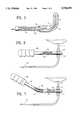
- FIG. 1is an elevational view, partially in section, of a channel forming device embodying features of the present invention.
- FIG. 2is a transverse cross-sectional view of the channel forming device shown in FIG. 1, taken along the lines 2--2.
- FIG. 3is a transverse cross-sectional view of the channel forming device shown in FIG. 1, taken along the lines 3--3.
- FIG. 4is a transverse cross-sectional view of the channel forming device shown in FIG. 1, taken along the lines 4--4.
- FIG. 5is an elevational view of a distal extremity of the device shown in FIG. 1 in which the probe tip has been deformed so as to curve into an L-shape.
- FIG. 6is an elevational view of the channel forming device shown in FIG. 1 secured by a stiff handle to facilitate placement of the channel forming means.
- FIG. 7is an elevational view of the channel forming device shown in FIG. 1 secured by a shapable handle to facilitate placement of the channel forming means.
- FIGS. 1-4a channel forming device 10 is shown embodying features of the invention.
- the device 10includes an elongated optical fiber 11, an elongated probe 12 disposed about and secured to the distal extremity of the optical fiber, and an outer tubular support member 13 secured to the exterior of the proximal extremity of the probe 12 and a distal portion of the optical fiber which is not disposed in the interior chamber 14 of the probe 12.
- the exterior of the optical fiber 11is provided with a fluoropolymeric cladding 15 along its length except for the distal portion 16 which extends into the distal portion of the interior chamber 14.
- the elongated probe 12has a cylindrical body 17 which is bonded to the optical fiber 11 by adhesive 18.
- the probe 12has a bulbous distal end 19 which acts as a lens to control laser energy emitted from the distal end of the optical fiber to a location immediately distal to the lens to ensure formation a channel of a desired size.
- the cylindrical body 17is provided with a coating or jacket 20 of suitable plastic material which will aid in the bonding of the outer tubular support member 13, strengthen the probe 12 and maintain the integrity of the probe, if the lens material fractures.
- the plastic materialis a heat shrinkable materials such as polyethylene terephthalate (PET) or polyethylene.
- the optical fiber 11 within the elongated probe 12is provided with a body of adhesive 18 which prevents relative longitudinal movement between the optical fiber and the elongated probe 12.
- a fluoropolymer buffer 22is disposed about the optical fiber 11 proximal to the body of adhesive 18 and extends proximally along essentially the remainder of the optical fiber.
- An outer jacket 23is disposed about the fluoropolymer buffer 22 along its length, and terminates within the outer support tubular support member 13 proximal to the elongated probe 12.
- Filler tubing 24is provided on the exterior of the buffer 22 and generally extends from the distal end of jacket 23 to the adhesive 18.
- the outer tubular support member 13has an outer and inner tubular elements 25 and 26 with the distal ends thereof forming a annular shoulder 27 which acts to limit the penetration of the probe 12 into the channel as it is being formed and thus the depth of the channel.
- the outer tubular element 25is longer than the inner tubular element 26 and the proximal end of the outer tubular member is secured to the exterior of jacket 23.
- the inner tubular member 26is secured to the filler shrink tubing 24 and the coating 20 on the cylindrical body 17 of the elongated probe 12.
- the inner and outer tubular elements 25 and 26are preferably formed of heat shrinkable materials such as polyethylene so that these elements can be heat shrunk onto the proximal extremity of the probe 11 and the distal extremity of the optical fiber which does not extend into the probe 12 and secure these members together.
- Other means of securing the outer tubular support member 13 to the optical fiber 11 and the elongated probe 12may be employed, such as a suitable adhesive or insert injection molding.
- the proximal end of the device 10is provided with a connector 28 which has a rotatable, internally threaded collar 29 which facilitates an optical connection with a source of laser energy.
- FIG. 5illustrates an alternative embodiment where the distal extremity of the device 10 is formed into an L-shape to facilitate the use of the device on the posterior side of the patient's heart.
- the channel forming device 10 shownis formed by forming the distal extremity of the optical fiber-probe subassembly in the desired shape at relatively high temperature and then cooling the subassembly in the formed shape.
- the outer tubular member and other elementsmay be added after the distal extremity has been shaped.
- FIGS. 6 and 7illustrate a handle 30 which is secured to the channel forming device 10 at a location on the exterior of the outer tubular support member 13 so that forces are applied to the probe 12 rather than the optical fiber 11.
- An annular rubber or elastomeric gasket 31is provided in an aperture in the distal end of the handle 30 facilitate a firm but soft grasp of the elongated probe member 12.
- the device 10is merely pushed into the passageway of the annular gasket 31 which is sized to frictionally engage a portion of the outer tubular support member 13 to thereby stabilize and hold device 10 while it is being pressed against the patient's epicardium to form the channel.
- a variety of other locking or holding elementscan be used.
- the handle 30 as shownis formed of metal shaft 32 and a plastic coating or jacket 33.
- a suitable metalis aluminum which is light weight and nonmagnetic.
- the handle 30may comprise a proximal section 34 and a distal section 35 with a flexible junction 36.
- the flexible junctionis formed of malleable material such as annealed aluminum and is covered with a accordioned plastic jacket 37.
- the various components of the device 10may be formed of a wide variety of conventional materials used in the construction of intravascular catheters and other intracorporeal devices.
- the contemplated materials of construction and the sources thereof for one presently preferred embodimentare provided in the following table.
- the overall length of channel forming deviceis about 200 to about 400 cm with a typical value being about 350 cm, with the actual length being determined by the location of the source of laser energy.
- the operative distal portion of the devicei.e. the portion which is inserted into the patient is about 10 to about 50 cm.
- the probe tipis about 1 to about 5 cm in length with the length of the exposed distal portion which extends out of the tubular support member being about 0.75 to about 2.5 cm, preferably about 1.25 to about 2 cm.
- the outer diameter of the probe tipis about 1 to about 3 mm, preferably about 1.5 to about 2 mm, and is measured at the widest portion of the bulbous tip which forms the lens.
- the outer diameter of the coating or jacket on the probe tipis essentially the same as the bulbous tip.
- the length Of the outer tubular support memberis about 15 to about 40 cm, preferably about 20 to about 30 cm and the radial dimension of the shoulder stop formed by the distal end of the outer tubular support member is about 0.5 to about
Landscapes
- Health & Medical Sciences (AREA)
- Surgery (AREA)
- Physics & Mathematics (AREA)
- Life Sciences & Earth Sciences (AREA)
- Heart & Thoracic Surgery (AREA)
- Medical Informatics (AREA)
- Nuclear Medicine, Radiotherapy & Molecular Imaging (AREA)
- Electromagnetism (AREA)
- Engineering & Computer Science (AREA)
- Biomedical Technology (AREA)
- Optics & Photonics (AREA)
- Otolaryngology (AREA)
- Molecular Biology (AREA)
- Animal Behavior & Ethology (AREA)
- General Health & Medical Sciences (AREA)
- Public Health (AREA)
- Veterinary Medicine (AREA)
- Laser Surgery Devices (AREA)
- Radiation-Therapy Devices (AREA)
- Media Introduction/Drainage Providing Device (AREA)
Abstract
Description
______________________________________ COMPONENT MATERIAL SUPPLIER ______________________________________ Proximal Optical Various Amphenol Corporation Connector Lisle, IL and Spectran.sup.1 Specialty Optics, Co. Avon, CT Proximal Strain Raychem Corporation Relief Thermostat Systems Division Menlo Park, CA 94025 Jacket (23) Pebax 7233 tubing North America Infinity with 3% TiO.sub.2 Extrusions and Engi- neering, Inc. Santa Clara, CA 95054 Filler Shrink Polyolefin, 1/16" Raychem Corporation Tubing (24) (RNF-100) Thermostat Systems Division Menlo Park, CA 94025 Tubular Element Polyolefin, 1/8" Raychem Corporation (26) (RNF-100) Thermostat Systems Division Menlo Park, CA 94025 Inner Tubular Polyolefin, 1/16" Raychem Corporation Element (25) (RNF-100) Thermostat Systems Division Menlo Park, CA 94025 UV-Cured Urethane Oligomer Dymax Corp. Adhesive (18) (197-M) Acrylate Torrington, CT PET Shrink Polyethylene Advanced Polymers, Inc. Tubing (19) Terephthalate Salem, NH Probe (12) Fused Quartz Polymicro Technologies, Inc. Phoenix, AZ Optical Fiber Tefzel ® Spectran.sup.1 Specialty Optic Co. Buffer (22) Avon, CT Optical Fiber Propietary Spectran.sup.1 Specialty Optic Co. Cladding (15) Flouropolymer Avon, CT Acrylate Optical Fiber (11) Fused Silica (Low Spectran.sup.1 Specialty Optic Co. OH) Avon, CT ______________________________________ .sup.1 Components sold in a finished subassembly. Part No. HCL M0365T.
Claims (9)
Priority Applications (12)
| Application Number | Priority Date | Filing Date | Title |
|---|---|---|---|
| US08/482,125US5728091A (en) | 1995-06-07 | 1995-06-07 | Optical fiber for myocardial channel formation |
| US08/584,957US6039727A (en) | 1995-06-07 | 1996-01-11 | Channel forming device with penetration limiter |
| CA002223949ACA2223949A1 (en) | 1995-06-07 | 1996-06-04 | Optical probe for myocardial channel formation |
| JP9501393AJPH11506959A (en) | 1995-06-07 | 1996-06-04 | Optical probe for myocardial channel formation |
| EP96917199AEP0831745A1 (en) | 1995-06-07 | 1996-06-04 | Optical probe for myocardial channel formation |
| PCT/US1996/008949WO1996039962A1 (en) | 1995-06-07 | 1996-06-04 | Optical probe for myocardial channel formation |
| PCT/US1996/009160WO1996039965A1 (en) | 1995-06-07 | 1996-06-05 | Surgical channel forming device with penetration limiter |
| AT96918208TATE231363T1 (en) | 1995-06-07 | 1996-06-05 | SURGICAL DEVICE PROVIDED WITH A PENETRATION DEPTH LIMITER FOR CREATING CHANNELS |
| CA002223943ACA2223943A1 (en) | 1995-06-07 | 1996-06-05 | Surgical channel forming device with penetration limiter |
| DE69625903TDE69625903T2 (en) | 1995-06-07 | 1996-06-05 | SURGICAL DEVICE FOR GENERATING CHANNELS WITH A PENETRATION DEPTH LIMITER |
| EP96918208AEP0830088B1 (en) | 1995-06-07 | 1996-06-05 | Surgical channel forming device with penetration limiter |
| JP9501549AJPH11509114A (en) | 1995-06-07 | 1996-06-05 | Surgical channel forming device having a penetration limiter |
Applications Claiming Priority (1)
| Application Number | Priority Date | Filing Date | Title |
|---|---|---|---|
| US08/482,125US5728091A (en) | 1995-06-07 | 1995-06-07 | Optical fiber for myocardial channel formation |
Related Child Applications (1)
| Application Number | Title | Priority Date | Filing Date |
|---|---|---|---|
| US08/584,957Continuation-In-PartUS6039727A (en) | 1995-06-07 | 1996-01-11 | Channel forming device with penetration limiter |
Publications (1)
| Publication Number | Publication Date |
|---|---|
| US5728091Atrue US5728091A (en) | 1998-03-17 |
Family
ID=23914792
Family Applications (2)
| Application Number | Title | Priority Date | Filing Date |
|---|---|---|---|
| US08/482,125Expired - LifetimeUS5728091A (en) | 1995-06-07 | 1995-06-07 | Optical fiber for myocardial channel formation |
| US08/584,957Expired - LifetimeUS6039727A (en) | 1995-06-07 | 1996-01-11 | Channel forming device with penetration limiter |
Family Applications After (1)
| Application Number | Title | Priority Date | Filing Date |
|---|---|---|---|
| US08/584,957Expired - LifetimeUS6039727A (en) | 1995-06-07 | 1996-01-11 | Channel forming device with penetration limiter |
Country Status (5)
| Country | Link |
|---|---|
| US (2) | US5728091A (en) |
| EP (1) | EP0831745A1 (en) |
| JP (1) | JPH11506959A (en) |
| CA (1) | CA2223949A1 (en) |
| WO (1) | WO1996039962A1 (en) |
Cited By (41)
| Publication number | Priority date | Publication date | Assignee | Title |
|---|---|---|---|---|
| US6102905A (en)* | 1994-09-09 | 2000-08-15 | Cardiofocus, Inc. | Phototherapy device including housing for an optical element and method of making |
| US6106546A (en)* | 1988-10-11 | 2000-08-22 | The General Hospital Corporation | Inducing vasodilation |
| US6162214A (en)* | 1997-10-30 | 2000-12-19 | Eclipse Surgical Technologies, Inc. | Corning device for myocardial revascularization |
| US6263880B1 (en) | 1998-06-22 | 2001-07-24 | Neovasys, Inc. | Method of enhancing blood flow in tissue |
| US20020092535A1 (en)* | 1996-06-19 | 2002-07-18 | Wilk Patent Development Corp. | Coronary artery by-pass method |
| US6464693B1 (en)* | 2000-03-06 | 2002-10-15 | Plc Medical Systems, Inc. | Myocardial revascularization |
| US20020164145A1 (en)* | 2001-05-04 | 2002-11-07 | Mccann Peter R. | Fiber optic wafer probe |
| WO2003013641A2 (en) | 2001-08-10 | 2003-02-20 | The Government Of The United States Of America As Represented By The Secretary Of The Department Of Health And Human Services | Side-exit catheter and method for its use |
| US20050047478A1 (en)* | 2003-08-29 | 2005-03-03 | Yu Chu Yih | Deflectable probe and thermometer |
| US20050096643A1 (en)* | 2003-10-30 | 2005-05-05 | Medical Cv, Inc. | Apparatus and method for laser treatment |
| US20050182392A1 (en)* | 2003-10-30 | 2005-08-18 | Medical Cv, Inc. | Apparatus and method for guided ablation treatment |
| US20050209589A1 (en)* | 2003-10-30 | 2005-09-22 | Medical Cv, Inc. | Assessment of lesion transmurality |
| US20060076669A1 (en)* | 2003-08-29 | 2006-04-13 | Mesure Technology Co., Ltd. | Deflectable probe and thermometer |
| US20060084960A1 (en)* | 2003-10-30 | 2006-04-20 | Medicalcv Inc. | Guided ablation with end-fire fiber |
| US7161363B2 (en) | 2002-05-23 | 2007-01-09 | Cascade Microtech, Inc. | Probe for testing a device under test |
| US20070073280A1 (en)* | 2005-09-16 | 2007-03-29 | Medicalcv, Inc. | End-fire guided ablation |
| US20070073277A1 (en)* | 2005-09-16 | 2007-03-29 | Medicalcv, Inc. | Controlled guided ablation treatment |
| US20070073281A1 (en)* | 2005-09-16 | 2007-03-29 | Medicalcv, Inc. | Guided ablation with motion control |
| US7233160B2 (en) | 2000-12-04 | 2007-06-19 | Cascade Microtech, Inc. | Wafer probe |
| US7271603B2 (en) | 2003-05-23 | 2007-09-18 | Cascade Microtech, Inc. | Shielded probe for testing a device under test |
| US7285969B2 (en) | 2002-11-13 | 2007-10-23 | Cascade Microtech, Inc. | Probe for combined signals |
| US7403028B2 (en) | 2006-06-12 | 2008-07-22 | Cascade Microtech, Inc. | Test structure and probe for differential signals |
| US20080188843A1 (en)* | 2002-07-10 | 2008-08-07 | Appling William M | Device and method for endovascular treatment for causing closure of a blood vessel |
| US7420381B2 (en) | 2004-09-13 | 2008-09-02 | Cascade Microtech, Inc. | Double sided probing structures |
| US7427868B2 (en) | 2003-12-24 | 2008-09-23 | Cascade Microtech, Inc. | Active wafer probe |
| US7443186B2 (en) | 2006-06-12 | 2008-10-28 | Cascade Microtech, Inc. | On-wafer test structures for differential signals |
| US7449899B2 (en) | 2005-06-08 | 2008-11-11 | Cascade Microtech, Inc. | Probe for high frequency signals |
| US7504842B2 (en) | 1997-05-28 | 2009-03-17 | Cascade Microtech, Inc. | Probe holder for testing of a test device |
| US7535247B2 (en) | 2005-01-31 | 2009-05-19 | Cascade Microtech, Inc. | Interface for testing semiconductors |
| US7609077B2 (en) | 2006-06-09 | 2009-10-27 | Cascade Microtech, Inc. | Differential signal probe with integral balun |
| US7619419B2 (en) | 2005-06-13 | 2009-11-17 | Cascade Microtech, Inc. | Wideband active-passive differential signal probe |
| US7656172B2 (en) | 2005-01-31 | 2010-02-02 | Cascade Microtech, Inc. | System for testing semiconductors |
| US7723999B2 (en) | 2006-06-12 | 2010-05-25 | Cascade Microtech, Inc. | Calibration structures for differential signal probing |
| US7764072B2 (en) | 2006-06-12 | 2010-07-27 | Cascade Microtech, Inc. | Differential signal probing system |
| US7876114B2 (en) | 2007-08-08 | 2011-01-25 | Cascade Microtech, Inc. | Differential waveguide probe |
| US9782562B2 (en) | 2002-04-04 | 2017-10-10 | Angiodynamics, Inc. | Venous insufficiency treatment method |
| US9814513B2 (en) | 2011-06-30 | 2017-11-14 | Angiodynamics, Inc. | Endovascular plasma treatment device and method of use |
| US11576724B2 (en) | 2011-02-24 | 2023-02-14 | Eximo Medical Ltd. | Hybrid catheter for vascular intervention |
| US11684420B2 (en) | 2016-05-05 | 2023-06-27 | Eximo Medical Ltd. | Apparatus and methods for resecting and/or ablating an undesired tissue |
| US12038322B2 (en) | 2022-06-21 | 2024-07-16 | Eximo Medical Ltd. | Devices and methods for testing ablation systems |
| US12376904B1 (en) | 2020-09-08 | 2025-08-05 | Angiodynamics, Inc. | Dynamic laser stabilization and calibration system |
Families Citing this family (54)
| Publication number | Priority date | Publication date | Assignee | Title |
|---|---|---|---|---|
| US6179824B1 (en) | 1993-05-10 | 2001-01-30 | Arthrocare Corporation | System and methods for electrosurgical restenosis of body lumens |
| US5683366A (en)* | 1992-01-07 | 1997-11-04 | Arthrocare Corporation | System and method for electrosurgical tissue canalization |
| US5697882A (en) | 1992-01-07 | 1997-12-16 | Arthrocare Corporation | System and method for electrosurgical cutting and ablation |
| US6749604B1 (en) | 1993-05-10 | 2004-06-15 | Arthrocare Corporation | Electrosurgical instrument with axially-spaced electrodes |
| US6915806B2 (en) | 1993-05-10 | 2005-07-12 | Arthrocare Corporation | Method for harvesting graft vessel |
| US6896674B1 (en) | 1993-05-10 | 2005-05-24 | Arthrocare Corporation | Electrosurgical apparatus having digestion electrode and methods related thereto |
| US6283955B1 (en) | 1996-05-13 | 2001-09-04 | Edwards Lifesciences Corp. | Laser ablation device |
| US5980545A (en)* | 1996-05-13 | 1999-11-09 | United States Surgical Corporation | Coring device and method |
| US5807383A (en)* | 1996-05-13 | 1998-09-15 | United States Surgical Corporation | Lasing device |
| US6620155B2 (en) | 1996-07-16 | 2003-09-16 | Arthrocare Corp. | System and methods for electrosurgical tissue contraction within the spine |
| US5755682A (en) | 1996-08-13 | 1998-05-26 | Heartstent Corporation | Method and apparatus for performing coronary artery bypass surgery |
| US5947989A (en)* | 1996-12-12 | 1999-09-07 | United States Surgical Corporation | Method and apparatus for transmyocardial revascularization |
| US6086534A (en)* | 1997-03-07 | 2000-07-11 | Cardiogenesis Corporation | Apparatus and method of myocardial revascularization using ultrasonic pulse-echo distance ranging |
| US6855143B2 (en) | 1997-06-13 | 2005-02-15 | Arthrocare Corporation | Electrosurgical systems and methods for recanalization of occluded body lumens |
| US7435247B2 (en) | 1998-08-11 | 2008-10-14 | Arthrocare Corporation | Systems and methods for electrosurgical tissue treatment |
| US6641610B2 (en) | 1998-09-10 | 2003-11-04 | Percardia, Inc. | Valve designs for left ventricular conduits |
| US6254564B1 (en) | 1998-09-10 | 2001-07-03 | Percardia, Inc. | Left ventricular conduit with blood vessel graft |
| AU6384699A (en) | 1998-09-10 | 2000-04-03 | Percardia, Inc. | Tmr shunt |
| US6290728B1 (en) | 1998-09-10 | 2001-09-18 | Percardia, Inc. | Designs for left ventricular conduit |
| JP2002524196A (en) | 1998-09-10 | 2002-08-06 | パーカーディア,インコーポレイティド | Transmyocardial shunt for left ventricular revascularization and its mounting mechanism |
| US6349460B1 (en)* | 1999-01-21 | 2002-02-26 | At&T Corp | Fiber installation method and apparatus |
| US6409697B2 (en) | 1999-05-04 | 2002-06-25 | Heartstent Corporation | Transmyocardial implant with forward flow bias |
| US7033372B1 (en) | 1999-08-04 | 2006-04-25 | Percardia, Inc. | Corkscrew reinforced left ventricle to coronary artery channel |
| US6638237B1 (en) | 1999-08-04 | 2003-10-28 | Percardia, Inc. | Left ventricular conduits and methods for delivery |
| US6854467B2 (en) | 2000-05-04 | 2005-02-15 | Percardia, Inc. | Methods and devices for delivering a ventricular stent |
| US6582400B1 (en) | 2000-10-24 | 2003-06-24 | Scimed Life Systems, Inc. | Variable tip catheter |
| US6976990B2 (en) | 2001-01-25 | 2005-12-20 | Percardia, Inc. | Intravascular ventriculocoronary bypass via a septal passageway |
| US6966906B2 (en) | 2001-06-08 | 2005-11-22 | Joe Denton Brown | Deflection mechanism for a surgical instrument, such as a laser delivery device and/or endoscope, and method of use |
| US6949118B2 (en) | 2002-01-16 | 2005-09-27 | Percardia, Inc. | Encased implant and methods |
| US7008397B2 (en) | 2002-02-13 | 2006-03-07 | Percardia, Inc. | Cardiac implant and methods |
| US20040054257A1 (en)* | 2002-05-31 | 2004-03-18 | Brown Joe D. | Deflection mechanism for a surgical instrument, and method of use |
| US7326219B2 (en) | 2002-09-09 | 2008-02-05 | Wilk Patent Development | Device for placing transmyocardial implant |
| US7374564B2 (en)* | 2002-10-08 | 2008-05-20 | Brown Joe D | Apparatus and method for causing deflection of a surgical instrument |
| US20050049613A1 (en)* | 2003-06-26 | 2005-03-03 | Brown Joe D. | In vivo deflection device and method |
| DE102005003632A1 (en) | 2005-01-20 | 2006-08-17 | Fraunhofer-Gesellschaft zur Förderung der angewandten Forschung e.V. | Catheter for the transvascular implantation of heart valve prostheses |
| US7896915B2 (en) | 2007-04-13 | 2011-03-01 | Jenavalve Technology, Inc. | Medical device for treating a heart valve insufficiency |
| US9044318B2 (en) | 2008-02-26 | 2015-06-02 | Jenavalve Technology Gmbh | Stent for the positioning and anchoring of a valvular prosthesis |
| BR112012021347A2 (en) | 2008-02-26 | 2019-09-24 | Jenavalve Tecnology Inc | stent for positioning and anchoring a valve prosthesis at an implantation site in a patient's heart |
| US8355799B2 (en) | 2008-12-12 | 2013-01-15 | Arthrocare Corporation | Systems and methods for limiting joint temperature |
| US10856978B2 (en) | 2010-05-20 | 2020-12-08 | Jenavalve Technology, Inc. | Catheter system |
| WO2011147849A1 (en) | 2010-05-25 | 2011-12-01 | Jenavalve Technology Inc. | Prosthetic heart valve and transcatheter delivered endoprosthesis comprising a prosthetic heart valve and a stent |
| US9662458B2 (en)* | 2010-12-23 | 2017-05-30 | Richard A. Schatz | Injection needle insertion barrier |
| CN105491978A (en) | 2013-08-30 | 2016-04-13 | 耶拿阀门科技股份有限公司 | Radially collapsible frame for a prosthetic valve and method for manufacturing such a frame |
| WO2015048795A2 (en) | 2013-09-30 | 2015-04-02 | Biocardia, Inc. | Radial and trans-endocardial delivery catheter |
| US9526556B2 (en) | 2014-02-28 | 2016-12-27 | Arthrocare Corporation | Systems and methods systems related to electrosurgical wands with screen electrodes |
| US9597142B2 (en) | 2014-07-24 | 2017-03-21 | Arthrocare Corporation | Method and system related to electrosurgical procedures |
| US9649148B2 (en) | 2014-07-24 | 2017-05-16 | Arthrocare Corporation | Electrosurgical system and method having enhanced arc prevention |
| US9788981B2 (en)* | 2014-11-20 | 2017-10-17 | Medtronic, Inc. | Systems for deploying medical diagnostics and/or therapy and delivery tools thereof |
| EP3270825B1 (en) | 2015-03-20 | 2020-04-22 | JenaValve Technology, Inc. | Heart valve prosthesis delivery system |
| US10709555B2 (en) | 2015-05-01 | 2020-07-14 | Jenavalve Technology, Inc. | Device and method with reduced pacemaker rate in heart valve replacement |
| US11278352B2 (en)* | 2016-05-05 | 2022-03-22 | Optical Integrity, Inc. | Protective caps of tips for surgical laser fibers |
| WO2017195125A1 (en) | 2016-05-13 | 2017-11-16 | Jenavalve Technology, Inc. | Heart valve prosthesis delivery system and method for delivery of heart valve prosthesis with introducer sheath and loading system |
| WO2018138658A1 (en) | 2017-01-27 | 2018-08-02 | Jenavalve Technology, Inc. | Heart valve mimicry |
| WO2024102411A1 (en) | 2022-11-09 | 2024-05-16 | Jenavalve Technology, Inc. | Catheter system for sequential deployment of an expandable implant |
Citations (17)
| Publication number | Priority date | Publication date | Assignee | Title |
|---|---|---|---|---|
| DE3443073A1 (en)* | 1984-11-26 | 1986-05-28 | Günther Dr. 8000 München Nath | Light-guide arrangement for endoscopes |
| US4658817A (en)* | 1985-04-01 | 1987-04-21 | Children's Hospital Medical Center | Method and apparatus for transmyocardial revascularization using a laser |
| US4740047A (en)* | 1985-03-26 | 1988-04-26 | Hatachi Cable, Ltd. | Fiber for lateral beaming of laser beam |
| EP0292621A1 (en)* | 1987-05-26 | 1988-11-30 | Surgical Laser Technologies, Inc. | Contact or insertion laser probe having wide angle radiation |
| US4860743A (en)* | 1986-10-27 | 1989-08-29 | University Of Florida | Laser method and apparatus for the recanalization of vessels and the treatment of other cardiac conditions |
| US4890898A (en)* | 1988-08-18 | 1990-01-02 | Hgm Medical Laser Systems, Inc. | Composite microsize optical fiber-electric lead cable |
| US4917084A (en)* | 1985-07-31 | 1990-04-17 | C. R. Bard, Inc. | Infrared laser catheter system |
| GB2227103A (en)* | 1989-01-11 | 1990-07-18 | Masahiko Hoshino | Laser apparatus for medical treatment |
| DE3911796A1 (en)* | 1989-04-11 | 1990-10-18 | Messerschmitt Boelkow Blohm | Myocardial probe for location and treatment of heart defects - has laser source, potential sensing electrode and light emitting cap capable of large area deep tissue therapy |
| US4967745A (en)* | 1987-04-10 | 1990-11-06 | Massachusetts Institute Of Technology | Multi-fiber plug for a laser catheter |
| US5093877A (en)* | 1990-10-30 | 1992-03-03 | Advanced Cardiovascular Systems | Optical fiber lasing apparatus lens |
| US5125926A (en)* | 1990-09-24 | 1992-06-30 | Laser Engineering, Inc. | Heart-synchronized pulsed laser system |
| US5129895A (en)* | 1990-05-16 | 1992-07-14 | Sunrise Technologies, Inc. | Laser sclerostomy procedure |
| US5342355A (en)* | 1992-10-19 | 1994-08-30 | Laser Centers Of America | Energy delivering cap element for end of optic fiber conveying laser energy |
| EP0622051A1 (en)* | 1993-04-29 | 1994-11-02 | S.L.T. Japan Co, Ltd. | Laser light irradiation apparatus |
| US5380316A (en)* | 1990-12-18 | 1995-01-10 | Advanced Cardiovascular Systems, Inc. | Method for intra-operative myocardial device revascularization |
| US5389096A (en)* | 1990-12-18 | 1995-02-14 | Advanced Cardiovascular Systems | System and method for percutaneous myocardial revascularization |
Family Cites Families (15)
| Publication number | Priority date | Publication date | Assignee | Title |
|---|---|---|---|---|
| GB227103A (en)* | 1923-12-31 | 1925-04-23 | Otto Reiss | Improvements in toys |
| US3982541A (en)* | 1974-07-29 | 1976-09-28 | Esperance Jr Francis A L | Eye surgical instrument |
| US4660571A (en)* | 1985-07-18 | 1987-04-28 | Cordis Corporation | Percutaneous lead having radially adjustable electrode |
| DE3718139C1 (en)* | 1987-05-29 | 1988-12-08 | Strahlen Umweltforsch Gmbh | Cardiac catheter |
| DE3803697A1 (en)* | 1988-02-08 | 1989-08-17 | Wolfgang Arno Karl Dr Radtke | LASER - VALVOTOMY - CATHETER (HEART CATHETER FOR PERCUTANICALLY TARGETED VALVOTOMY OF NARROWED HEART VALVES) |
| US5037421A (en)* | 1989-10-06 | 1991-08-06 | Coherent, Inc., Medical Group | Mid-infrared laser arthroscopic procedure |
| US5700259A (en)* | 1990-09-24 | 1997-12-23 | Plc Medical Systems, Inc. | Thoracoscopic transmyocardial revascularization handpiece assembly |
| WO1994020037A1 (en)* | 1993-03-03 | 1994-09-15 | American Medical Systems, Inc. | Apparatus and method for interstitial treatment |
| US5492119A (en)* | 1993-12-22 | 1996-02-20 | Heart Rhythm Technologies, Inc. | Catheter tip stabilizing apparatus |
| US5447529A (en)* | 1994-01-28 | 1995-09-05 | Philadelphia Heart Institute | Method of using endocardial impedance for determining electrode-tissue contact, appropriate sites for arrhythmia ablation and tissue heating during ablation |
| US5643253A (en)* | 1995-06-06 | 1997-07-01 | Rare Earth Medical, Inc. | Phototherapy apparatus with integral stopper device |
| US5669907A (en)* | 1995-02-10 | 1997-09-23 | Valleylab Inc. | Plasma enhanced bipolar electrosurgical system |
| US5666970A (en)* | 1995-05-02 | 1997-09-16 | Heart Rhythm Technologies, Inc. | Locking mechanism for catheters |
| US5725521A (en)* | 1996-03-29 | 1998-03-10 | Eclipse Surgical Technologies, Inc. | Depth stop apparatus and method for laser-assisted transmyocardial revascularization and other surgical applications |
| US5672170A (en)* | 1996-06-20 | 1997-09-30 | Cynosure, Inc. | Laser transmyocardial revascularization arrangement |
- 1995
- 1995-06-07USUS08/482,125patent/US5728091A/ennot_activeExpired - Lifetime
- 1996
- 1996-01-11USUS08/584,957patent/US6039727A/ennot_activeExpired - Lifetime
- 1996-06-04WOPCT/US1996/008949patent/WO1996039962A1/ennot_activeApplication Discontinuation
- 1996-06-04EPEP96917199Apatent/EP0831745A1/ennot_activeWithdrawn
- 1996-06-04JPJP9501393Apatent/JPH11506959A/enactivePending
- 1996-06-04CACA002223949Apatent/CA2223949A1/ennot_activeAbandoned
Patent Citations (18)
| Publication number | Priority date | Publication date | Assignee | Title |
|---|---|---|---|---|
| DE3443073A1 (en)* | 1984-11-26 | 1986-05-28 | Günther Dr. 8000 München Nath | Light-guide arrangement for endoscopes |
| US4740047A (en)* | 1985-03-26 | 1988-04-26 | Hatachi Cable, Ltd. | Fiber for lateral beaming of laser beam |
| US4658817A (en)* | 1985-04-01 | 1987-04-21 | Children's Hospital Medical Center | Method and apparatus for transmyocardial revascularization using a laser |
| US4917084A (en)* | 1985-07-31 | 1990-04-17 | C. R. Bard, Inc. | Infrared laser catheter system |
| US4860743A (en)* | 1986-10-27 | 1989-08-29 | University Of Florida | Laser method and apparatus for the recanalization of vessels and the treatment of other cardiac conditions |
| US4967745A (en)* | 1987-04-10 | 1990-11-06 | Massachusetts Institute Of Technology | Multi-fiber plug for a laser catheter |
| EP0292621A1 (en)* | 1987-05-26 | 1988-11-30 | Surgical Laser Technologies, Inc. | Contact or insertion laser probe having wide angle radiation |
| US4890898A (en)* | 1988-08-18 | 1990-01-02 | Hgm Medical Laser Systems, Inc. | Composite microsize optical fiber-electric lead cable |
| US4985029A (en)* | 1989-01-11 | 1991-01-15 | Masahiko Hoshino | Laser apparatus for medical treatment |
| GB2227103A (en)* | 1989-01-11 | 1990-07-18 | Masahiko Hoshino | Laser apparatus for medical treatment |
| DE3911796A1 (en)* | 1989-04-11 | 1990-10-18 | Messerschmitt Boelkow Blohm | Myocardial probe for location and treatment of heart defects - has laser source, potential sensing electrode and light emitting cap capable of large area deep tissue therapy |
| US5129895A (en)* | 1990-05-16 | 1992-07-14 | Sunrise Technologies, Inc. | Laser sclerostomy procedure |
| US5125926A (en)* | 1990-09-24 | 1992-06-30 | Laser Engineering, Inc. | Heart-synchronized pulsed laser system |
| US5093877A (en)* | 1990-10-30 | 1992-03-03 | Advanced Cardiovascular Systems | Optical fiber lasing apparatus lens |
| US5380316A (en)* | 1990-12-18 | 1995-01-10 | Advanced Cardiovascular Systems, Inc. | Method for intra-operative myocardial device revascularization |
| US5389096A (en)* | 1990-12-18 | 1995-02-14 | Advanced Cardiovascular Systems | System and method for percutaneous myocardial revascularization |
| US5342355A (en)* | 1992-10-19 | 1994-08-30 | Laser Centers Of America | Energy delivering cap element for end of optic fiber conveying laser energy |
| EP0622051A1 (en)* | 1993-04-29 | 1994-11-02 | S.L.T. Japan Co, Ltd. | Laser light irradiation apparatus |
Non-Patent Citations (18)
| Title |
|---|
| Mirhoseini, "Laser Applications in Thoracic and Cardiovascular Surgery," Medical Instrumentation, vol. 17, No. 6, 401-403 (Nov.-Dec. 1982). |
| Mirhoseini, "Laser Revascularization of the Heart," in New Frontiers in Laser Medicine and Surgery (Atsumi, Editor), ISBN Elsevier Science Publishing Co., 296-303 (1982). |
| Mirhoseini, et al., "Lasers in Cardiothoracic Surgery," in Lasers in General Surgery (Joffe, Editor), Williams and Wilkins, 216-232 (1989). |
| Mirhoseini, et al., "Myocardial Revascularization by Laser: A Clinical Report," Lasers in Surgery and Medicine 3:241-245 (1983). |
| Mirhoseini, et al., "New Concepts in Revascularization of the Myocardium," A Thorac. Surg. 45:415-420 (Apr. 1988). |
| Mirhoseini, et al., "Revascularization of the Heart by Laser," Journal of Microsurgery 253-260 (Jun. 1981). |
| Mirhoseini, et al., "Transvenicular Revascularization by Laser," Lasers in Surgery and Medicine 2:187-198 (1982). |
| Mirhoseini, et al., Clinical Report: "Laser Myocardial Revascularization," Lasers in Surgery and Medicine 6:459-461 (1986). |
| Mirhoseini, et al., Clinical Report: Laser Myocardial Revascularization, Lasers in Surgery and Medicine 6:459 461 (1986).* |
| Mirhoseini, et al., Lasers in Cardiothoracic Surgery, in Lasers in General Surgery (Joffe, Editor), Williams and Wilkins, 216 232 (1989).* |
| Mirhoseini, et al., Myocardial Revascularization by Laser: A Clinical Report, Lasers in Surgery and Medicine 3:241 245 (1983).* |
| Mirhoseini, et al., New Concepts in Revascularization of the Myocardium, A Thorac. Surg. 45:415 420 (Apr. 1988).* |
| Mirhoseini, et al., Revascularization of the Heart by Laser, Journal of Microsurgery 253 260 (Jun. 1981).* |
| Mirhoseini, et al., Transvenicular Revascularization by Laser, Lasers in Surgery and Medicine 2:187 198 (1982).* |
| Mirhoseini, Laser Applications in Thoracic and Cardiovascular Surgery, Medical Instrumentation, vol. 17, No. 6, 401 403 (Nov. Dec. 1982).* |
| Mirhoseini, Laser Revascularization of the Heart, in New Frontiers in Laser Medicine and Surgery (Atsumi, Editor), ISBN Elsevier Science Publishing Co., 296 303 (1982).* |
| Walter, et al., Europ. Surg. Res. 3: 130 138 (1971).* |
| Walter, et al., Europ. Surg. Res. 3: 130-138 (1971). |
Cited By (83)
| Publication number | Priority date | Publication date | Assignee | Title |
|---|---|---|---|---|
| US6106546A (en)* | 1988-10-11 | 2000-08-22 | The General Hospital Corporation | Inducing vasodilation |
| US6102905A (en)* | 1994-09-09 | 2000-08-15 | Cardiofocus, Inc. | Phototherapy device including housing for an optical element and method of making |
| US20020092535A1 (en)* | 1996-06-19 | 2002-07-18 | Wilk Patent Development Corp. | Coronary artery by-pass method |
| US7504842B2 (en) | 1997-05-28 | 2009-03-17 | Cascade Microtech, Inc. | Probe holder for testing of a test device |
| US6162214A (en)* | 1997-10-30 | 2000-12-19 | Eclipse Surgical Technologies, Inc. | Corning device for myocardial revascularization |
| US6263880B1 (en) | 1998-06-22 | 2001-07-24 | Neovasys, Inc. | Method of enhancing blood flow in tissue |
| US6306125B1 (en) | 1998-06-22 | 2001-10-23 | Neovasys, Inc. | Angiogenic implant delivery system and method |
| US6464693B1 (en)* | 2000-03-06 | 2002-10-15 | Plc Medical Systems, Inc. | Myocardial revascularization |
| US6592576B2 (en)* | 2000-03-06 | 2003-07-15 | Plc Medical Systems, Inc. | Myocardial revascularization |
| US7456646B2 (en) | 2000-12-04 | 2008-11-25 | Cascade Microtech, Inc. | Wafer probe |
| US7233160B2 (en) | 2000-12-04 | 2007-06-19 | Cascade Microtech, Inc. | Wafer probe |
| US7495461B2 (en) | 2000-12-04 | 2009-02-24 | Cascade Microtech, Inc. | Wafer probe |
| US7761983B2 (en) | 2000-12-04 | 2010-07-27 | Cascade Microtech, Inc. | Method of assembling a wafer probe |
| US7688097B2 (en) | 2000-12-04 | 2010-03-30 | Cascade Microtech, Inc. | Wafer probe |
| US20060008226A1 (en)* | 2001-05-04 | 2006-01-12 | Cascade Microtech, Inc. | Fiber optic wafer probe |
| US20020164145A1 (en)* | 2001-05-04 | 2002-11-07 | Mccann Peter R. | Fiber optic wafer probe |
| US6970634B2 (en) | 2001-05-04 | 2005-11-29 | Cascade Microtech, Inc. | Fiber optic wafer probe |
| US7298536B2 (en) | 2001-05-04 | 2007-11-20 | Cascade Microtech, Inc. | Fiber optic wafer probe |
| WO2003013641A2 (en) | 2001-08-10 | 2003-02-20 | The Government Of The United States Of America As Represented By The Secretary Of The Department Of Health And Human Services | Side-exit catheter and method for its use |
| US9782562B2 (en) | 2002-04-04 | 2017-10-10 | Angiodynamics, Inc. | Venous insufficiency treatment method |
| US7489149B2 (en) | 2002-05-23 | 2009-02-10 | Cascade Microtech, Inc. | Shielded probe for testing a device under test |
| US7304488B2 (en) | 2002-05-23 | 2007-12-04 | Cascade Microtech, Inc. | Shielded probe for high-frequency testing of a device under test |
| US7436194B2 (en) | 2002-05-23 | 2008-10-14 | Cascade Microtech, Inc. | Shielded probe with low contact resistance for testing a device under test |
| US7518387B2 (en) | 2002-05-23 | 2009-04-14 | Cascade Microtech, Inc. | Shielded probe for testing a device under test |
| US7161363B2 (en) | 2002-05-23 | 2007-01-09 | Cascade Microtech, Inc. | Probe for testing a device under test |
| US7482823B2 (en) | 2002-05-23 | 2009-01-27 | Cascade Microtech, Inc. | Shielded probe for testing a device under test |
| US10238453B2 (en) | 2002-07-10 | 2019-03-26 | Angiodynamics, Inc. | Method of making an endovascular laser treatment device for causing closure of a blood vessel |
| US20080188843A1 (en)* | 2002-07-10 | 2008-08-07 | Appling William M | Device and method for endovascular treatment for causing closure of a blood vessel |
| US8864755B2 (en) | 2002-07-10 | 2014-10-21 | Angiodynamics, Inc. | Device and method for endovascular treatment for causing closure of a blood vessel |
| US8864754B2 (en) | 2002-07-10 | 2014-10-21 | Angiodynamics, Inc. | Device and method for endovascular treatment for causing closure of a blood vessel |
| US7285969B2 (en) | 2002-11-13 | 2007-10-23 | Cascade Microtech, Inc. | Probe for combined signals |
| US7453276B2 (en) | 2002-11-13 | 2008-11-18 | Cascade Microtech, Inc. | Probe for combined signals |
| US7417446B2 (en) | 2002-11-13 | 2008-08-26 | Cascade Microtech, Inc. | Probe for combined signals |
| US7271603B2 (en) | 2003-05-23 | 2007-09-18 | Cascade Microtech, Inc. | Shielded probe for testing a device under test |
| US7898273B2 (en) | 2003-05-23 | 2011-03-01 | Cascade Microtech, Inc. | Probe for testing a device under test |
| US7501842B2 (en) | 2003-05-23 | 2009-03-10 | Cascade Microtech, Inc. | Shielded probe for testing a device under test |
| US7498829B2 (en) | 2003-05-23 | 2009-03-03 | Cascade Microtech, Inc. | Shielded probe for testing a device under test |
| US20060076669A1 (en)* | 2003-08-29 | 2006-04-13 | Mesure Technology Co., Ltd. | Deflectable probe and thermometer |
| US20050047478A1 (en)* | 2003-08-29 | 2005-03-03 | Yu Chu Yih | Deflectable probe and thermometer |
| US6979122B2 (en)* | 2003-08-29 | 2005-12-27 | Mesure Technology Co., Ltd. | Deflectable probe and thermometer |
| US7303332B2 (en) | 2003-08-29 | 2007-12-04 | Mesure Technology Co., Ltd. | Deflectable probe and thermometer |
| US7338485B2 (en) | 2003-10-30 | 2008-03-04 | Medical Cv, Inc. | Cardiac lesions with continuity testing |
| US7232437B2 (en) | 2003-10-30 | 2007-06-19 | Medical Cv, Inc. | Assessment of lesion transmurality |
| US7267674B2 (en) | 2003-10-30 | 2007-09-11 | Medical Cv, Inc. | Apparatus and method for laser treatment |
| US20050096643A1 (en)* | 2003-10-30 | 2005-05-05 | Medical Cv, Inc. | Apparatus and method for laser treatment |
| US20060084960A1 (en)* | 2003-10-30 | 2006-04-20 | Medicalcv Inc. | Guided ablation with end-fire fiber |
| US7238179B2 (en) | 2003-10-30 | 2007-07-03 | Medical Cv, Inc. | Apparatus and method for guided ablation treatment |
| US20050143722A1 (en)* | 2003-10-30 | 2005-06-30 | Medical Cv, Inc. | Laser-based maze procedure for atrial fibrillation |
| US20050143721A1 (en)* | 2003-10-30 | 2005-06-30 | Medical Cv, Inc. | Malleable energy wand for maze procedure |
| US7238180B2 (en) | 2003-10-30 | 2007-07-03 | Medicalcv Inc. | Guided ablation with end-fire fiber |
| US20050209589A1 (en)* | 2003-10-30 | 2005-09-22 | Medical Cv, Inc. | Assessment of lesion transmurality |
| US20050159734A1 (en)* | 2003-10-30 | 2005-07-21 | Medical Cv, Inc. | Atraumatic laser tip for atrial fibrillation treatment |
| US20050171521A1 (en)* | 2003-10-30 | 2005-08-04 | Medical Cv, Inc. | Cardiac lesions with continuity testing |
| US20050182392A1 (en)* | 2003-10-30 | 2005-08-18 | Medical Cv, Inc. | Apparatus and method for guided ablation treatment |
| US7169142B2 (en)* | 2003-10-30 | 2007-01-30 | Medical Cv, Inc. | Malleable energy wand for maze procedure |
| US7163534B2 (en)* | 2003-10-30 | 2007-01-16 | Medical Cv, Inc. | Laser-based maze procedure for atrial fibrillation |
| US7137977B2 (en)* | 2003-10-30 | 2006-11-21 | Medical Cv, Inc. | Atraumatic laser tip for atrial fibrillation treatment |
| US7427868B2 (en) | 2003-12-24 | 2008-09-23 | Cascade Microtech, Inc. | Active wafer probe |
| US7759953B2 (en) | 2003-12-24 | 2010-07-20 | Cascade Microtech, Inc. | Active wafer probe |
| US8013623B2 (en) | 2004-09-13 | 2011-09-06 | Cascade Microtech, Inc. | Double sided probing structures |
| US7420381B2 (en) | 2004-09-13 | 2008-09-02 | Cascade Microtech, Inc. | Double sided probing structures |
| US7898281B2 (en) | 2005-01-31 | 2011-03-01 | Cascade Mircotech, Inc. | Interface for testing semiconductors |
| US7656172B2 (en) | 2005-01-31 | 2010-02-02 | Cascade Microtech, Inc. | System for testing semiconductors |
| US7940069B2 (en) | 2005-01-31 | 2011-05-10 | Cascade Microtech, Inc. | System for testing semiconductors |
| US7535247B2 (en) | 2005-01-31 | 2009-05-19 | Cascade Microtech, Inc. | Interface for testing semiconductors |
| US7449899B2 (en) | 2005-06-08 | 2008-11-11 | Cascade Microtech, Inc. | Probe for high frequency signals |
| US7619419B2 (en) | 2005-06-13 | 2009-11-17 | Cascade Microtech, Inc. | Wideband active-passive differential signal probe |
| US20070073277A1 (en)* | 2005-09-16 | 2007-03-29 | Medicalcv, Inc. | Controlled guided ablation treatment |
| US20070073281A1 (en)* | 2005-09-16 | 2007-03-29 | Medicalcv, Inc. | Guided ablation with motion control |
| US20070073280A1 (en)* | 2005-09-16 | 2007-03-29 | Medicalcv, Inc. | End-fire guided ablation |
| US7609077B2 (en) | 2006-06-09 | 2009-10-27 | Cascade Microtech, Inc. | Differential signal probe with integral balun |
| US7750652B2 (en) | 2006-06-12 | 2010-07-06 | Cascade Microtech, Inc. | Test structure and probe for differential signals |
| US7403028B2 (en) | 2006-06-12 | 2008-07-22 | Cascade Microtech, Inc. | Test structure and probe for differential signals |
| US7723999B2 (en) | 2006-06-12 | 2010-05-25 | Cascade Microtech, Inc. | Calibration structures for differential signal probing |
| US7443186B2 (en) | 2006-06-12 | 2008-10-28 | Cascade Microtech, Inc. | On-wafer test structures for differential signals |
| US7764072B2 (en) | 2006-06-12 | 2010-07-27 | Cascade Microtech, Inc. | Differential signal probing system |
| US7876114B2 (en) | 2007-08-08 | 2011-01-25 | Cascade Microtech, Inc. | Differential waveguide probe |
| US11576724B2 (en) | 2011-02-24 | 2023-02-14 | Eximo Medical Ltd. | Hybrid catheter for vascular intervention |
| US12042223B2 (en) | 2011-02-24 | 2024-07-23 | Eximo Medical Ltd. | Hybrid catheter for vascular intervention |
| US9814513B2 (en) | 2011-06-30 | 2017-11-14 | Angiodynamics, Inc. | Endovascular plasma treatment device and method of use |
| US11684420B2 (en) | 2016-05-05 | 2023-06-27 | Eximo Medical Ltd. | Apparatus and methods for resecting and/or ablating an undesired tissue |
| US12376904B1 (en) | 2020-09-08 | 2025-08-05 | Angiodynamics, Inc. | Dynamic laser stabilization and calibration system |
| US12038322B2 (en) | 2022-06-21 | 2024-07-16 | Eximo Medical Ltd. | Devices and methods for testing ablation systems |
Also Published As
| Publication number | Publication date |
|---|---|
| CA2223949A1 (en) | 1996-12-19 |
| WO1996039962A1 (en) | 1996-12-19 |
| EP0831745A1 (en) | 1998-04-01 |
| US6039727A (en) | 2000-03-21 |
| JPH11506959A (en) | 1999-06-22 |
Similar Documents
| Publication | Publication Date | Title |
|---|---|---|
| US5728091A (en) | Optical fiber for myocardial channel formation | |
| US6132451A (en) | Optical fiber for myocardial channel formation | |
| EP0830088B1 (en) | Surgical channel forming device with penetration limiter | |
| US5951567A (en) | Introducer for channel forming device | |
| US6251104B1 (en) | Guiding catheter system for ablating heart tissue | |
| US6093177A (en) | Catheter with flexible intermediate section | |
| US5441496A (en) | Laser delivery system with soft tip | |
| US6592576B2 (en) | Myocardial revascularization | |
| US6102905A (en) | Phototherapy device including housing for an optical element and method of making | |
| US20020052621A1 (en) | Circumferential pulmonary vein ablation using a laser and fiberoptic balloon catheter | |
| JP2008516638A (en) | Removal probe with reinforcing member | |
| EP0868923A3 (en) | Steerable catheter | |
| US20040204704A1 (en) | Device and method for dacryocystorhinostomy | |
| US20090182225A1 (en) | Safety Marked Fibers and Catheters | |
| US7998130B2 (en) | System for connecting a compatibility liner with a source of perishable therapeutic | |
| EP2194905A1 (en) | Device for the use, also single use, of an optical fiber for invasive surgical laser treatment in the human body | |
| JPH0342897Y2 (en) | ||
| JPS62210404A (en) | Fiber for laser beam transmission |
Legal Events
| Date | Code | Title | Description |
|---|---|---|---|
| STCF | Information on status: patent grant | Free format text:PATENTED CASE | |
| AS | Assignment | Owner name:ECLIPSE SURGICAL TECHNOLOGIES, INC., CALIFORNIA Free format text:ASSIGNMENT OF ASSIGNORS INTEREST;ASSIGNOR:CARDIOGENESIS CORPORATION;REEL/FRAME:010247/0272 Effective date:19990823 | |
| FEPP | Fee payment procedure | Free format text:PAYOR NUMBER ASSIGNED (ORIGINAL EVENT CODE: ASPN); ENTITY STATUS OF PATENT OWNER: SMALL ENTITY | |
| FPAY | Fee payment | Year of fee payment:4 | |
| REMI | Maintenance fee reminder mailed | ||
| FPAY | Fee payment | Year of fee payment:8 | |
| SULP | Surcharge for late payment | Year of fee payment:7 | |
| FPAY | Fee payment | Year of fee payment:12 | |
| AS | Assignment | Owner name:GENERAL ELECTRIC CAPITAL CORPORATION, AS AGENT, MA Free format text:SECURITY AGREEMENT;ASSIGNOR:CARDIOGENESIS CORPORATION;REEL/FRAME:026540/0064 Effective date:20110630 | |
| AS | Assignment | Owner name:CRYOLIFE, INC., GEORGIA Free format text:MERGER;ASSIGNOR:CARDIOGENESIS CORPORATION;REEL/FRAME:034723/0249 Effective date:20141231 | |
| AS | Assignment | Owner name:GENERAL ELECTRIC CAPITAL CORPORATION, AS AGENT, MARYLAND Free format text:SECURITY INTEREST;ASSIGNOR:CRYOLIFE, INC.;REEL/FRAME:034947/0248 Effective date:20150209 Owner name:GENERAL ELECTRIC CAPITAL CORPORATION, AS AGENT, MA Free format text:SECURITY INTEREST;ASSIGNOR:CRYOLIFE, INC.;REEL/FRAME:034947/0248 Effective date:20150209 | |
| AS | Assignment | Owner name:HEALTHCARE FINANCIAL SOLUTIONS, LLC, AS SUCCESSOR AGENT, MARYLAND Free format text:ASSIGNMENT OF INTELLECTUAL PROPERTY SECURITY AGREEMENT;ASSIGNOR:GENERAL ELECTRIC CAPITAL CORPORATION, AS RETIRING AGENT;REEL/FRAME:037146/0466 Effective date:20151118 Owner name:HEALTHCARE FINANCIAL SOLUTIONS, LLC, AS SUCCESSOR Free format text:ASSIGNMENT OF INTELLECTUAL PROPERTY SECURITY AGREEMENT;ASSIGNOR:GENERAL ELECTRIC CAPITAL CORPORATION, AS RETIRING AGENT;REEL/FRAME:037146/0466 Effective date:20151118 | |
| AS | Assignment | Owner name:HEALTHCARE FINANCIAL SOLUTIONS, LLC, AS AGENT, MARYLAND Free format text:SECURITY INTEREST;ASSIGNORS:CRYOLIFE, INC., AS GRANTOR;VALVE SPECIAL PURPOSE CO., LLC, AS GRANTOR;ON-X LIFE TECHNOLOGIES, INC., AS GRANTOR;REEL/FRAME:037569/0212 Effective date:20160120 Owner name:HEALTHCARE FINANCIAL SOLUTIONS, LLC, AS AGENT, MAR Free format text:SECURITY INTEREST;ASSIGNORS:CRYOLIFE, INC., AS GRANTOR;VALVE SPECIAL PURPOSE CO., LLC, AS GRANTOR;ON-X LIFE TECHNOLOGIES, INC., AS GRANTOR;REEL/FRAME:037569/0212 Effective date:20160120 | |
| AS | Assignment | Owner name:ON-X LIFE TECHNOLOGIES, INC. (F/K/A MCRI, INC.), GEORGIA Free format text:RELEASE OF SECURITY INTEREST IN PATENTS;ASSIGNOR:HEALTHCARE FINANCIAL SOLUTIONS, LLC, AS ADMINISTRATIVE AGENT;REEL/FRAME:044621/0240 Effective date:20171201 Owner name:CARDIOGENESIS CORPORATION (N/K/A CRYOLIFE, INC.), GEORGIA Free format text:RELEASE OF SECURITY INTEREST IN PATENTS;ASSIGNOR:HEALTHCARE FINANCIAL SOLUTIONS, LLC, AS ADMINISTRATIVE AGENT;REEL/FRAME:044621/0240 Effective date:20171201 Owner name:CARDIOGENESIS CORPORATION (N/K/A CRYOLIFE, INC.), Free format text:RELEASE OF SECURITY INTEREST IN PATENTS;ASSIGNOR:HEALTHCARE FINANCIAL SOLUTIONS, LLC, AS ADMINISTRATIVE AGENT;REEL/FRAME:044621/0240 Effective date:20171201 Owner name:CRYOLIFE ACQUISITION CORPORATION, GEORGIA Free format text:RELEASE OF SECURITY INTEREST IN PATENTS;ASSIGNOR:HEALTHCARE FINANCIAL SOLUTIONS, LLC, AS ADMINISTRATIVE AGENT;REEL/FRAME:044621/0240 Effective date:20171201 Owner name:ON-X LIFE TECHNOLOGIES, INC. (F/K/A MCRI, INC.), G Free format text:RELEASE OF SECURITY INTEREST IN PATENTS;ASSIGNOR:HEALTHCARE FINANCIAL SOLUTIONS, LLC, AS ADMINISTRATIVE AGENT;REEL/FRAME:044621/0240 Effective date:20171201 Owner name:VALVE SPECIAL PURPOSE CO., LLC, GEORGIA Free format text:RELEASE OF SECURITY INTEREST IN PATENTS;ASSIGNOR:HEALTHCARE FINANCIAL SOLUTIONS, LLC, AS ADMINISTRATIVE AGENT;REEL/FRAME:044621/0240 Effective date:20171201 Owner name:HEMOSPHERE, INC., GEORGIA Free format text:RELEASE OF SECURITY INTEREST IN PATENTS;ASSIGNOR:HEALTHCARE FINANCIAL SOLUTIONS, LLC, AS ADMINISTRATIVE AGENT;REEL/FRAME:044621/0240 Effective date:20171201 Owner name:CRYOLIFE, INC., GEORGIA Free format text:RELEASE OF SECURITY INTEREST IN PATENTS;ASSIGNOR:HEALTHCARE FINANCIAL SOLUTIONS, LLC, AS ADMINISTRATIVE AGENT;REEL/FRAME:044621/0240 Effective date:20171201 |