US5727802A - Suspension wheelchair and wheelchair frame - Google Patents
Suspension wheelchair and wheelchair frameDownload PDFInfo
- Publication number
- US5727802A US5727802AUS08/711,313US71131396AUS5727802AUS 5727802 AUS5727802 AUS 5727802AUS 71131396 AUS71131396 AUS 71131396AUS 5727802 AUS5727802 AUS 5727802A
- Authority
- US
- United States
- Prior art keywords
- lower frame
- wheelchair
- frame members
- suspension
- upper frame
- Prior art date
- Legal status (The legal status is an assumption and is not a legal conclusion. Google has not performed a legal analysis and makes no representation as to the accuracy of the status listed.)
- Expired - Fee Related
Links
Images


Classifications
- A—HUMAN NECESSITIES
- A61—MEDICAL OR VETERINARY SCIENCE; HYGIENE
- A61G—TRANSPORT, PERSONAL CONVEYANCES, OR ACCOMMODATION SPECIALLY ADAPTED FOR PATIENTS OR DISABLED PERSONS; OPERATING TABLES OR CHAIRS; CHAIRS FOR DENTISTRY; FUNERAL DEVICES
- A61G5/00—Chairs or personal conveyances specially adapted for patients or disabled persons, e.g. wheelchairs
- A61G5/10—Parts, details or accessories
- A61G5/1056—Arrangements for adjusting the seat
- A61G5/1075—Arrangements for adjusting the seat tilting the whole seat backwards
- A—HUMAN NECESSITIES
- A61—MEDICAL OR VETERINARY SCIENCE; HYGIENE
- A61G—TRANSPORT, PERSONAL CONVEYANCES, OR ACCOMMODATION SPECIALLY ADAPTED FOR PATIENTS OR DISABLED PERSONS; OPERATING TABLES OR CHAIRS; CHAIRS FOR DENTISTRY; FUNERAL DEVICES
- A61G5/00—Chairs or personal conveyances specially adapted for patients or disabled persons, e.g. wheelchairs
- A61G5/08—Chairs or personal conveyances specially adapted for patients or disabled persons, e.g. wheelchairs foldable
- A61G5/0808—Chairs or personal conveyances specially adapted for patients or disabled persons, e.g. wheelchairs foldable characterised by a particular folding direction
- A61G5/0816—Chairs or personal conveyances specially adapted for patients or disabled persons, e.g. wheelchairs foldable characterised by a particular folding direction folding side to side, e.g. reducing or expanding the overall width of the wheelchair
- A61G5/0825—Chairs or personal conveyances specially adapted for patients or disabled persons, e.g. wheelchairs foldable characterised by a particular folding direction folding side to side, e.g. reducing or expanding the overall width of the wheelchair comprising a scissor-type frame, e.g. having pivoting cross bars for enabling folding
- A—HUMAN NECESSITIES
- A61—MEDICAL OR VETERINARY SCIENCE; HYGIENE
- A61G—TRANSPORT, PERSONAL CONVEYANCES, OR ACCOMMODATION SPECIALLY ADAPTED FOR PATIENTS OR DISABLED PERSONS; OPERATING TABLES OR CHAIRS; CHAIRS FOR DENTISTRY; FUNERAL DEVICES
- A61G5/00—Chairs or personal conveyances specially adapted for patients or disabled persons, e.g. wheelchairs
- A61G5/08—Chairs or personal conveyances specially adapted for patients or disabled persons, e.g. wheelchairs foldable
- A61G5/0883—Chairs or personal conveyances specially adapted for patients or disabled persons, e.g. wheelchairs foldable having locking means for maintaining a folded or unfolded condition
- A—HUMAN NECESSITIES
- A61—MEDICAL OR VETERINARY SCIENCE; HYGIENE
- A61G—TRANSPORT, PERSONAL CONVEYANCES, OR ACCOMMODATION SPECIALLY ADAPTED FOR PATIENTS OR DISABLED PERSONS; OPERATING TABLES OR CHAIRS; CHAIRS FOR DENTISTRY; FUNERAL DEVICES
- A61G5/00—Chairs or personal conveyances specially adapted for patients or disabled persons, e.g. wheelchairs
- A61G5/08—Chairs or personal conveyances specially adapted for patients or disabled persons, e.g. wheelchairs foldable
- A61G5/0891—Chairs or personal conveyances specially adapted for patients or disabled persons, e.g. wheelchairs foldable having rigid supports, e.g. seat or back supports which retain their shape after folding of the wheelchair
- A—HUMAN NECESSITIES
- A61—MEDICAL OR VETERINARY SCIENCE; HYGIENE
- A61G—TRANSPORT, PERSONAL CONVEYANCES, OR ACCOMMODATION SPECIALLY ADAPTED FOR PATIENTS OR DISABLED PERSONS; OPERATING TABLES OR CHAIRS; CHAIRS FOR DENTISTRY; FUNERAL DEVICES
- A61G5/00—Chairs or personal conveyances specially adapted for patients or disabled persons, e.g. wheelchairs
- A61G5/10—Parts, details or accessories
- A61G5/1054—Large wheels, e.g. higher than the seat portion
- A—HUMAN NECESSITIES
- A61—MEDICAL OR VETERINARY SCIENCE; HYGIENE
- A61G—TRANSPORT, PERSONAL CONVEYANCES, OR ACCOMMODATION SPECIALLY ADAPTED FOR PATIENTS OR DISABLED PERSONS; OPERATING TABLES OR CHAIRS; CHAIRS FOR DENTISTRY; FUNERAL DEVICES
- A61G5/00—Chairs or personal conveyances specially adapted for patients or disabled persons, e.g. wheelchairs
- A61G5/10—Parts, details or accessories
- A61G5/1078—Parts, details or accessories with shock absorbers or other suspension arrangements between wheels and frame
- A—HUMAN NECESSITIES
- A61—MEDICAL OR VETERINARY SCIENCE; HYGIENE
- A61G—TRANSPORT, PERSONAL CONVEYANCES, OR ACCOMMODATION SPECIALLY ADAPTED FOR PATIENTS OR DISABLED PERSONS; OPERATING TABLES OR CHAIRS; CHAIRS FOR DENTISTRY; FUNERAL DEVICES
- A61G5/00—Chairs or personal conveyances specially adapted for patients or disabled persons, e.g. wheelchairs
- A61G5/10—Parts, details or accessories
- A61G5/1081—Parts, details or accessories with shock absorbers or other suspension arrangements between frame and seat
- A—HUMAN NECESSITIES
- A61—MEDICAL OR VETERINARY SCIENCE; HYGIENE
- A61G—TRANSPORT, PERSONAL CONVEYANCES, OR ACCOMMODATION SPECIALLY ADAPTED FOR PATIENTS OR DISABLED PERSONS; OPERATING TABLES OR CHAIRS; CHAIRS FOR DENTISTRY; FUNERAL DEVICES
- A61G5/00—Chairs or personal conveyances specially adapted for patients or disabled persons, e.g. wheelchairs
- A61G5/10—Parts, details or accessories
- A61G5/1097—Camber- or toe-adjusting means for the drive wheels
Definitions
- the present inventionrelates to wheelchairs and particularly to wheelchair frames having suspension systems.
- a wheelchair useris continually exposed to considerable vibrations and impact forces from the wheelchair rolling over irregular surfaces, going up or down steps and curbs, and rolling over other obstacles.
- various deviceshave been proposed for minimizing the forces that are transmitted through the chair to the user. These devices focus on attaching the main drive wheels to a pivot arm and a shock absorbing device to absorb vibration and impact forces through movement of the drive wheels and pivot arm.
- U.S. Pat. No. 4,572,533(Ellis et at.), U.S. Pat. No. 4,190,263 (Powers) and U.S. Pat. No. 4,078,817 (Ferguson et at.) each disclose an apparatus which can be mounted on a conventional wheelchair.
- Each drive wheel of the wheelchairis removed and attached to the apparatus so that the main frame members of the wheelchair remain rigid.
- the drive wheel and the apparatusmove substantially in a vertical direction to absorb the shock.
- U.S. Pat. No. 4,861,056discloses a folding wheelchair having a suspension system comprising a pair of suspension wings pivotally mounted to the wheelchair frame by a pivot block. Each drive wheel axle is rotatably attached to the rearward end of the suspension wing. The forward end of the suspension wing engages a spring or shock absorber which, in turn, attaches to the wheelchair frame. As uneven terrain is encountered, the suspension wing and thus the drive wheel pivots on the pivot block to reduce the shock transmitted to the occupant.
- U.S. Pat. No. 4,455,031discloses a wheelchair having a rear suspension support frame having its front end pivotally connected to the wheelchair frame and the main drive wheels attached at the rear end to opposite sides of the rear suspension support frame.
- a shock absorberis connected between the main wheelchair frame and the rear suspension support frame.
- U.S. Pat. No. 3,917,312(Rodaway) discloses a C-shaped frame having left and right caster wheels being mounted to the left and right free ends of the lower arms of the C-shaped frames so that the upper arms are cantilevered from the rear drive wheels.
- the caster wheelsare independently resiliently supported for up and down movement relative to the seat.
- the present inventionprovides a suspension wheelchair, and in particular a wheelchair frame, that provides desirable characteristics in a suspension wheelchair, while overcoming the disadvantages of the prior art devices.
- a wheelchair frame in accordance with this inventionincludes a pair of side frame assemblies, a connector connecting the two side frame assemblies, a seat, caster wheel mountings, drive wheel mountings, and a leg rest mounting.
- Each of the side frame assemblieshave an upper frame member and a lower frame member.
- the upper frame memberis pivotally connected at its forward end to the forward portion of the lower frame member and supported at its rearward end by a suspension support member (i.e., shock absorber) connected to the rearward end of the lower frame member.
- the seatis attached between the upper frame members of each side frame assembly. With this configuration, the upper frame members and the seat are free to pivot about the pivotal connection between the upper frame member and the lower frame member.
- the upper frame members and seatfloat up and down on the shock absorber to provide cushioning to the user.
- the drive wheels, caster wheels and the lower frame membersremain rigid and true and therefore enabling the wheelchair to maintain its full stability, wheel alignment and maneuverability while absorbing shocks.
- a wheelchair framecomprising a pair of side frame assemblies, each of said side frame assemblies comprising an upper frame member and a lower frame member, said upper frame member being pivotally connected at a forward end to said lower frame member; a caster wheel mounting; a drive wheel mounting; and a foot rest mounting; connecting means connecting said pair of side frame assemblies; and a suspension support member connecting said upper frame member and said lower frame member so that said upper frame member is supported by said suspension support member and pivots at the forward end about the pivotal connection.
- a wheelchaircomprising a pair of side frame assemblies, each of said side frame assemblies comprising an upper frame member and a lower frame member which are connected by a flexible connection at a forward end of said upper frame member; a caster wheel mounting having a caster wheel; a drive wheel mounting having a drive wheel; a footrest mounting having a footrest; a connector connecting said pair of side frame assemblies; a seat between said pair of side frame assemblies; and a suspension member connecting said upper frame member and said lower frame member so that said upper frame member is supported by said suspension member and moves at the forward end about the flexible connection.
- a foldaable wheelchaircomprising a pair of side frame assemblies, each of said side frame assemblies comprising an upper frame member pivotally connected at a forward end to a lower frame member; a caster wheel mounting connected to the lower frame member; a drive wheel mounting connected to the lower frame member; and a foot rest mounting connected to the side frame assembly at a forward end; folding connector means for connecting said pair of side frame assemblies; and a suspension member connecting said upper frame member and said lower frame member so that said upper frame member is supported by said suspension member and pivots at the forward end about the pivotal connection.
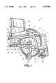
- FIG. 1is a perspective view of one embodiment of a wheelchair frame and mounting assembly for the suspension system in accordance with the present invention
- FIG. 2is an enlarged fight side view of another embodiment of the mounting assembly for the suspension system in accordance with the present invention.
- FIG. 3is an exploded view of one embodiment of a pivotal connection in accordance with the present invention.
- FIG. 4is an exploded view of a flexible connection in another embodiment of the present invention.
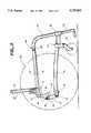
- FIG. 5is a right side view of the suspension system in its normal position and its compressed position
- FIG. 6is a perspective view of one embodiment of a wheelchair frame with a stabilizer bar in accordance with the present invention.
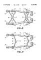
- FIG. 7is a perspective view of a folding wheelchair frame in accordance with the present invention.
- FIG. 8is a top plan view of a folding mechanism in one embodiment of the present invention.
- FIG. 9is a top plan view of a folding mechanism in accordance with another embodiment of the present invention.
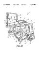
- FIG. 10is a perspective view of one embodiment of a wheelchair frame with one suspension member in accordance with the present invention.
- a wheelchair and wheelchair frame 1having a pair of side frame assemblies 2, 4.
- Each side frame assembly 2, 4includes a lower frame member 6, 8, an upper frame member 10, 12 and a footrest member 14, 16. It is contemplated that footrest member 14, 16 can be omitted and the lower frame member 6, 8 extends up to meet upper frame member 10, 12 or upper frame member 10, 12 can extend down to meet lower frame member 6, 8.
- a seat pan 18extends between the upper frame members 10, 12.
- the seat pan 18can be mounted in a groove formed in each of the upper frame members 10, 12.
- the seat pan 18can be of a rigid construction in order to perform a structurally supportive function. That is, the seat pan 18 can be fabricated as a sandwich laminate that includes a pair of outside or skin layers separated by a sandwich core.
- a cushion 20can be positioned on the seat pan 18.
- a padded cover 15can also be provided to protect the user's legs and to aid in transferring in and out of the wheelchair.
- the two side frame assemblies 2, 4are substantially identical in construction, or are mirror image construction to the extent needed for assembly of mated pairs. Thus, the following description of features pertaining to one of the side frame assemblies 4 is equally applicable to the other side frame assembly 2.
- the lower frame member 8includes a rear mounting bracket 22.
- the rear mounting bracket 22has a suspension member support portion 21 and a base portion 23.
- the suspension member support portion 21is provided with at least one through hole.
- Suitable securing means 25, such as a pin or a nut and bolt,can be provided to secure the suspension support member 30 to the suspension member support portion 21 in a fixed or pivotal fashion.
- the securing means 25is removable to allow changing suspension support member 30.
- the lower frame member 8also includes a straight portion or rear region 24 extending from the rear mounting bracket 22 and a portion 26 extending downward and forward that is connected to the footrest member 16 by way of a lug 28.
- the lug 28is attached by an adhesive bond or by mechanical means to both the downward forward portion 26 of the lower frame member 8 and to the footrest member 16.
- the upper frame member 12extends from an opposite end of the footrest member 16 to the upper mounting bracket 31.
- the upper frame member 12is structurally connected to the suspension support member 30 by way of upper mounting bracket 31.
- One portion 32 of the upper mounting bracket 31is provided with at least one through hole.
- Suitable securing means 34such as a pin or a nut and bolt, can be provided to secure the suspension support member 30 to the upper mounting bracket 31 in a fixed or pivotal fashion.
- the securing means 34is removable to allow changing suspension support member 30.
- an adjustable mounting bracket 33 having a plurality of mounting holes 35can be attached between the upper mounting bracket 31 and suspension support member 30.
- Securing means 34such as a pin or a nut and bolt, can be used to secure the suspension support member 30 to the adjustable mounting bracket 33 in a fixed or pivotal fashion.
- the securing means 34is removable to allow changing suspension support member 30.
- Securing means 37such as a pin or a nut and bolt, can be used to removably secure the adjustable mounting bracket 33 to the upper mounting bracket 31.
- the mounting holes 35are disposed along an arc having a radius that originates at the pivotal or flexible connection 46 (FIG. 5) about which the upper frame member 12 rotates.
- the securing means 37can be mounted in any of the mounting holes 35 in order to adjust the upper frame member 12 (and seat) to a desired angle relative to a horizontal plane without affecting the center of gravity of the wheelchair, the caster alignment, or the position of the drive wheels.
- adjustment of the upper frame member 12 (and seat) to a desired anglewill not create tow-in or tow-out, change the camber of the drive wheels, or change the proper alignment of suspension support member 30.
- the rear mounting bracket 22 and upper mounting bracket 31are preferably fabricated of cast magnesium or aluminum. However, other materials such as fiber reinforced plastic composite material could be employed.
- the upper mounting bracket 31is also pivotally connected to a seat back frame member 36 which serves as a mounting structure for a seat back cushion 38.
- the upper mounting bracket 31is pivotally connected to the seat back frame member 36 by way of a pivot connection 40.
- the upper mounting bracket 31is also provided with an elongated arcuate slot 42 through which extends a pin 44 that is connected to the seat back frame member 36.
- the seat back frame member 36can pivot about the pivot connection 40 relative to the seat cushion 20. In that way, the seat back cushion 38 can be inclined or not inclined to the extent desired by the user.
- the ends of the generally arcuate slot 42 and the upper mounting bracket 31define the extent of the pivotal movement allowed by the seat back frame member 36.
- the pin 44 or other appropriate securing arrangementallows the seat back frame member 36 to be secured at the desired position.
- the suspension support member 30(represented diagrammatically) mounted between the rear mounting bracket 22 and the upper mounting bracket 31 acts to dampen and/or absorb the vibrations and shock forces the wheelchair experiences from the drive wheels encountering irregularities and obstacles on the road surface.
- the suspension support member 30can be any of a variety of elements known to one of ordinary skill in the art, such as elastomers, springs, gas shock absorbers, oil shock absorbers, elastomeric shock absorbers, a leaf spring, a torsion bar, an air bladder, etc.
- the suspension support member 30also acts as a support member for the user.
- One of ordinary skill in the artcan select the proper suspension support member 30 based on its load bearing and energy absorption characteristics.
- the shockshould be stiff enough to maintain rigidity of the wheelchair while also providing the desired damping. It is desirable that when the suspension support member deflects that it remains flexible and does not bind or stick in the axial direction which could result in losses in overall shock efficiency.
- the suspension support memberUpon impact with an obstacle, the suspension support member should absorb a large percentage of the impact energy and efficiently transmit it to another form, such as deformations if an elastomer is used.
- a "multiple stage" suspension support membercan be used to absorb a wide range and variety of impacts.
- various elastomer materialscan be used in combination together, or in combination with other materials such as springs to absorb large impacts (e.g., dropping off curbs) and small impacts (e.g., uneven paved roads, door jams).
- each "stage" of elastomerwill efficiently damp out certain special impacts.
- the suspension support membermay have a preload adjustment mechanism so that the user can select a firm ride or a soft ride, or "tune" each stage to their preference. It is desirable that each or some of the individual stages in the suspension support member be interchangeable by the user so that the user can modify the suspension support member characteristics to his/her particular needs.
- a single suspension support member 30(represented diagrammatically) is used (FIG. 10)
- the single suspension support memberis centered between the two side frame assemblies and connected between a lower mounting bracket 112 attached to a connector member located between the two lower frame members and an upper mounting bracket 114 attached to the bottom of the seat pan.
- the suspension support members in either the dual suspension support member wheelchair or the single suspension support member wheelchaircan be replaced with a rigid member or locked in a given position to provide conventional rigidity to the wheelchair for a period of time if the user desires, such as for sports use where stiffness is important.
- a horizontal stabilizer 39(FIG. 6) can be incorporated to prevent lateral movement of the upper frame with respect to the lower frame.
- the horizontal stabilizer 39is attached to upper frame member 10 by vertical support 41 and to lower frame member 8 by vertical support 43.
- the movable connections, such as pin connections 53,55,allow horizontal stabilizer 39 to move vertically as the upper frame members 10, 12 move up and down while maintaining lateral stability of the upper frame relative to the lower frame.
- the upper frame member 12can be connected to the footrest member 16 by a pivot joint and lug assembly that includes pivot lug fork 47, pivot lug plug 49 and pivot pin 45 (FIG. 3). Each of the lugs 47, 49 can be adhesively bonded to the foot rest member 16 and the upper frame member 12, respectively.
- the upper frame member 12can be connected to the footrest member 16 by a flexible coupling element 51 (FIG. 4).
- the flexible coupling elementcan be any of a variety of elements that bend such as a reinforced coil spring with a protective accordion housing, a tightly coiled spring, an elastomer, a leaf spring, etc.
- the coupling elementneed only be sufficiently strong enough to support part of the weight of the user and be flexible enough to allow the upper frame members to move rotationally or substantially upward and downward.
- the pivot jointcan be a ball and socket connection.
- the pivot connection or flexible connection 46can be located at any desired position along the upper frame or lower frame. It is desirable, if the pivot connection or flexible connection is along the upper frame, that the connection be forward of the seat pan 18. If the pivot connection or flexible connection is along the lower frame, then it is preferable that the connection be forward of the caster mounting assembly 74 to maintain proper wheel alignment when the support member 30 compresses. It is usually preferred that the pivot connection be above the lug 28 so that when the suspension support members 30 compress, the footrest and the user's feet are not translated forward, i.e., the wheelchair does not increase in overall length. In one embodiment, upper frame member 12 and foot rest member 16 can be merged into a single member, and pivot point 48 can be positioned at lug 28. A preferred embodiment is shown in FIGS. 1 and 5, wherein pivot point 48 is positioned between the upper frame member 12 and the foot rest member 16 just forward of the forward edge of seat pan 18.
- FIG. 5shows the location of each element of the wheelchair when the suspension support member 30 is compressed to suspension support member position 30'.
- the upper frame member 12rotates about the flexible connection 46 to upper frame member position 12'.
- lower frame member 8 and caster mounting assembly 74maintain their positions and therefore remain in proper alignment. In other words, the drive wheels and caster wheels remain true.
- the angle of the seat pan relative to a horizontal planecan fluctuate in response to forces transmitted through the suspension support member from the drive wheels without affecting the center of gravity of the wheelchair. Further, the seat pan angle can fluctuate without affecting, changing or altering the trueness, camber, or alignment of the drive wheels 50 or the alignment of caster wheels 52 or the caster mounting assembly 74.
- the movement of the upper mounting bracket 31 along an arc whose radius originates from the pivot or flexible connection 46is quite advantageous as it helps to ensure that fluctuation of the seat pan angle will not alter any other characteristic of the wheelchair or suspension support member.
- the entire wheelchair, except for the upper frame members 10, 12 and the seat members,is fixed in space while the upper frame members 10, 12 are free to rotate about the connection 46 at the forward region of the frame.
- upper frame members 10, 12 along with the seat pan 18rotate or move upward and downward in such a way so that no other aspect or characteristic of the wheelchair such as the position of the drive wheels 50, the vertical orientation (camber) of the drive wheels, the position of the casters 52, or the vertical orientation (caster) of the longitudinal axis of the caster stem is changed.
- the drive wheel mounting assembly 54can include a lower mounting block 56, an upper mounting block 58 and a drive wheel axle receiving element 60.
- the drive wheel axle receiving element 60can include a mounting plate portion 62 and an axle receiving portion 64. Further, the mounting plate portion 62 and the axle receiving portion 64 can be integral with one another and formed in one piece.
- the drive wheel axle receiving element 60can be connected to the upper mounting block 58 by any suitable connecting means 66, such as bolts and nuts.
- the connecting means 66is preferably selected to allow the upper mounting block 58 and the drive wheel axle receiving element 60 to be disconnected from one another.
- the lower mounting block 56can be connected to the upper mounting block 58 by any suitable connecting means similar to connecting means 66.
- the connecting meanswill allow the lower mounting block 56 and upper mounting block 58 to be disconnected from one another.
- connecting means 66may connect the drive wheel axle receiving element 60, the upper mounting block 58, and the lower mounting block 56 all together.
- the drive wheel axle receiving dement 60can help to define the camber and tow-in of the drive wheels 50.
- the rear region 24 of the lower frame member 8can be provided with a plurality of spaced apart indexing keys or teeth that are preferably integral with and formed unitarily with the lower frame member.
- the indexing keys on the lower frame member 8 associated with the one side frame assembly 4are preferably aligned with the indexing keys on the lower frame member 6 associated with the other side frame assembly 2.
- the drive wheel mounting assembly 54 positioned on each lower frame member 6, 8can be positioned at the same place along the respective lower frame member 6, 8 to ensure that each of the drive wheels is at the same position.
- a drive wheel mounting assembly 54is secured to each of the bottom members 6, 8. Extending between each drive wheel mounting assembly 54 is a connecting means or connector such as rigid supporting member 68 which serves to connect the side frame assemblies 2, 4 to one another and impart rigidity to the wheelchair frame.
- the rigid supporting member 68 and the seat pan 18 that extends between the upper frame members 10, 12provide substantially all of the structural support and interconnection between the two side frame assemblies 2,4.
- the one piece footrest 70 that is connected to the footrest members 14, 16also contributes to the rigid interconnection of the two side frame assemblies 2, 4.
- a folding wheelchairis equipped with the suspension support system of the present invention (FIG. 7).
- a scissor-type folding mechanism 80is mounted parallel to or in the same plane as the seat pan 18 between upper frame members 10,12.
- Another scissor-type folding mechanism 80is mounted parallel to or in the same plane as the lower frame members 6,8.
- the folding mechanism 80(FIG. 8) has four support arms 82 that form an X-shape when the folding mechanism is fully extended.
- the support armsare pivotally attached to the locking mechanism 84 and the lower frame members 6,8.
- a locking mechanism 84secures the support arms 82 in place so that they do not retract or fold until the user releases the locking mechanism.
- the side frame assemblies 2,4are moved together and the support arms 82 pivot about their pivotal connections until they are substantially parallel with the upper frame members 10, 12 and lower frame members 6,8.
- the folding wheelchair 1has two separate footrests 70,71 attached to footrest members 16,14, respectively. Footrest 70,71 are usually pivotally attached to enable them to be folded out of the way when the chair is folded. In addition, seat pan 18, seat cushion 20, and seat back cushion 38 are flexible to facilitate folding of the wheelchair. In this way, the two scissor-type folding mechanisms 80 and support arms 82 provide substantially all of the structural support and interconnection between the two side frame assemblies 2,4. Additionally, a folding mechanism 86 comprising support arms 88 and locking mechanism 90 can be mounted parallel to or in the same plane as the forward end of the lower frame members 6,8 to provide added rigidity to the wheelchair.
- seat pan 18can be a rigid structural member that is either detachable at both sides or hinged to frame 12 at one side and detachable at the other side. In such case the seat pan can also provide part of the structural support and interconnection between the two side frame assemblies.
- FIGS. 7 and 8are only illustrative, many other folding mechanisms known to those of ordinary skill in the art can be used.
- FIG. 9shows folding mechanisms 92,98 in an unlocked position. Both folding mechanisms 92,98 are constructed the same except for dimensional differences of the support arms, therefore only one folding mechanism will be described.
- a similar folding mechanismcan be mounted between upper frame members 10, 12.
- Folding mechanism 92is comprised of support arms 94,95 which are pivotally connected to lower frame members 6,8 and to each other by pivot connection 96. When the folding mechanism 92 is in a locked position, the support arms 94,95 are axially aligned and provide lateral rigidity to the wheelchair.
- the side frame assemblies 2,4are moved together and the support arms 94,95 and 100, 101 pivot about their pivotal connections until they are substantially parallel with the side frame assemblies 2,4.
- different locking mechanismscan be used in combination with the folding mechanisms 92,98 to hold them in their locked position for a time as the user desires.
- One commonly known deviceis simply a sleeve that slides over the overlapping portions of the support arms 94,95.
- the folding mechanisms 92,98can be connected by a rigid member between the two pivotal connections 96 and 102 so that the two folding mechanisms can be operated at the same time.
- a plurality of drive wheel axle receiving elements 60can be provided, each of which has an axle receiving hole 72 inclined at a different angle and/or a mounting plate portion 62 having a different thickness. In that way, the drive wheels can be provided with more or less camber.
- the forward section of the lower frame member 8 and the upper frame member 12can be formed from any of a variety of materials such as aluminum tubing or fiber reinforced plastic composite material.
- the rear section of the lower frame member 8can be fabricated from any of a variety of materials such as magnesium, aluminum, or fiber reinforced plastic composite material.
- the front and rear sectionscan be fabricated of the same material or different materials.
- the wheelchair and wheelchair frame 1 illustrated in FIG. 1may also include the caster mounting assembly 74 which allows a caster wheel 52 to be secured to both of the lower frame members 6,8.
- a support arm 76is attached between the lug 28 and caster mounting assembly 74 in order to locate the caster wheels out from the lower frame members for greater stability of the wheelchair.
- the castersare able to be flipped forward or backward for stability.
- the caster mounting assembly 74can be attached to the support arm 76 by way of suitable connecting means such as nuts and bolts (not shown) or by being integrally formed with the mounting assembly 74.
Landscapes
- Health & Medical Sciences (AREA)
- Life Sciences & Earth Sciences (AREA)
- Animal Behavior & Ethology (AREA)
- General Health & Medical Sciences (AREA)
- Public Health (AREA)
- Veterinary Medicine (AREA)
- Handcart (AREA)
Abstract
Description
Claims (20)
Priority Applications (1)
| Application Number | Priority Date | Filing Date | Title |
|---|---|---|---|
| US08/711,313US5727802A (en) | 1994-07-14 | 1996-09-03 | Suspension wheelchair and wheelchair frame |
Applications Claiming Priority (3)
| Application Number | Priority Date | Filing Date | Title |
|---|---|---|---|
| US27482694A | 1994-07-14 | 1994-07-14 | |
| US57019595A | 1995-12-11 | 1995-12-11 | |
| US08/711,313US5727802A (en) | 1994-07-14 | 1996-09-03 | Suspension wheelchair and wheelchair frame |
Related Parent Applications (1)
| Application Number | Title | Priority Date | Filing Date |
|---|---|---|---|
| US57019595AContinuation | 1994-07-14 | 1995-12-11 |
Publications (1)
| Publication Number | Publication Date |
|---|---|
| US5727802Atrue US5727802A (en) | 1998-03-17 |
Family
ID=23049762
Family Applications (1)
| Application Number | Title | Priority Date | Filing Date |
|---|---|---|---|
| US08/711,313Expired - Fee RelatedUS5727802A (en) | 1994-07-14 | 1996-09-03 | Suspension wheelchair and wheelchair frame |
Country Status (2)
| Country | Link |
|---|---|
| US (1) | US5727802A (en) |
| DE (1) | DE19525719B4 (en) |
Cited By (56)
| Publication number | Priority date | Publication date | Assignee | Title |
|---|---|---|---|---|
| WO1999017700A1 (en)* | 1997-10-06 | 1999-04-15 | Invacare Corporation | Articulating seat/chassis interface for a wheelchair |
| WO2000027691A1 (en)* | 1998-11-12 | 2000-05-18 | Freedom Designs Incorporated | Two-piece side frame assembly for small wheelchairs |
| US6129165A (en) | 1996-07-03 | 2000-10-10 | Pride Mobility Products, Corporation | Curb-climbing power wheelchair |
| US6161856A (en)* | 1998-11-13 | 2000-12-19 | Invacare Corporation | Wheelchair suspension system |
| US6164674A (en)* | 1995-06-05 | 2000-12-26 | Adorno/Rogers Technology, Inc. | Adjustable wheelbase wheelchair |
| US6176335B1 (en) | 1996-07-03 | 2001-01-23 | Pride Mobility Products, Corporation | Power wheelchair |
| US6186252B1 (en) | 1996-07-03 | 2001-02-13 | Pride Mobility Products, Corporation | Foldable midwheel drive power chair |
| US6199647B1 (en) | 1996-07-03 | 2001-03-13 | Pride Mobility Products Corporation | Mid-wheel drive power wheelchair |
| US6270105B1 (en) | 1999-11-16 | 2001-08-07 | Da International, Ltd. | Method of wheelchair construction |
| US6302429B1 (en) | 1999-11-16 | 2001-10-16 | Da International, Ltd | Convertible wheelchair |
| US6352275B1 (en)* | 1998-01-22 | 2002-03-05 | Invacare Deutschland Gmbh | Wheelchair |
| US6394476B1 (en)* | 2000-08-10 | 2002-05-28 | Invacare Corporation | Wheelchair seat having adjustable telescoping assembly |
| US6412804B1 (en)* | 1997-05-30 | 2002-07-02 | M. Yves Dignat | Wheelchair with improved suspension |
| NL1017192C2 (en)* | 2001-01-25 | 2002-07-26 | Revab Bv | Wheelchair provided with a swiveling device near the knee of a user. |
| US6428029B1 (en) | 2001-02-09 | 2002-08-06 | Advanced Mobility Systems Corporation | Wheelchair frame |
| US6499762B1 (en) | 1995-06-05 | 2002-12-31 | Adorno/Rogers Technology, Inc. | Frame support apparatus and coupling device for use with an ambulatory system and method of fabrication thereof |
| US20030075365A1 (en)* | 2001-10-19 | 2003-04-24 | Fought Gerald E. | Wheelchair suspension having pivotal motor mount |
| US6554086B1 (en)* | 2000-10-27 | 2003-04-29 | Invacare Corporation | Obstacle traversing wheelchair |
| US6561524B1 (en)* | 2000-04-06 | 2003-05-13 | Henry Medina | Collapsible chair |
| US6572133B1 (en) | 2001-01-18 | 2003-06-03 | Sunrise Medical Hhg, Inc. | Folding mechanism for a wheelchair |
| US6601863B1 (en) | 1997-10-06 | 2003-08-05 | Invacare Corporation | Mid-wheel drive wheelchair with rigid front wheel anti-tip stabilizer |
| US20040060748A1 (en)* | 2001-10-10 | 2004-04-01 | Molnar James H. | Wheelchair suspension |
| US20040188152A1 (en)* | 2003-03-25 | 2004-09-30 | Schaffner Walter E. | Power wheelchair |
| US20050127631A1 (en)* | 2003-12-15 | 2005-06-16 | Schaffner Walter E. | Curb-climbing power wheelchair |
| US20050168033A1 (en)* | 2004-01-14 | 2005-08-04 | Invacare Corporation | Adjustable wheelchair |
| EP1362763A3 (en)* | 2002-05-15 | 2005-08-10 | Otto Bock HealthCare GmbH | Baby carriage, particularly for rehabilitation |
| US6979010B1 (en)* | 2004-06-01 | 2005-12-27 | Kwapis Randal J | Sport utility wheelchair |
| US20060076748A1 (en)* | 2004-10-08 | 2006-04-13 | Sunrise Medical Hhg Inc. | Wheelchair with damping mechanism |
| US20060076747A1 (en)* | 2004-10-08 | 2006-04-13 | Sunrise Medical Hhg Inc. | Wheelchair suspension system |
| US7032917B1 (en)* | 2002-09-19 | 2006-04-25 | Eric Mark Chelgren | Rear suspension for wheelchair |
| WO2006045316A1 (en) | 2004-10-29 | 2006-05-04 | R82 A/S | Comfort wheelchair |
| GB2425288A (en)* | 2005-04-20 | 2006-10-25 | Eric Lai | Structure of a wheelchair |
| US20060244249A1 (en)* | 2002-10-25 | 2006-11-02 | Gerold Goertzen | Suspension for wheeled vehicles |
| EP1721592A2 (en) | 2005-05-14 | 2006-11-15 | Specialised Orthotic Services Limited | Wheelchairs |
| US20080067777A1 (en)* | 2006-09-18 | 2008-03-20 | Dirk Dauw | Wheelchair |
| US20090032323A1 (en)* | 2005-04-14 | 2009-02-05 | Toyota Jidosha Kabushiki Kaisha | Coaxial two-wheel vehicle |
| US20090079159A1 (en)* | 2007-09-21 | 2009-03-26 | Michael Every | Foldable wheelchair |
| USD589411S1 (en)* | 2007-09-12 | 2009-03-31 | Pdg Inc. | Wheelchair member |
| US20090278325A1 (en)* | 2008-05-09 | 2009-11-12 | Chk Develop B.V. | Walking Aid Adapted For Mounting A Height Obstacle |
| US20100004820A1 (en)* | 2007-02-14 | 2010-01-07 | Invacare Corporation | Wheelchair with suspension |
| US20100038880A1 (en)* | 2008-08-15 | 2010-02-18 | Bagg Christian Peter Edward | Modular and/or configurable wheelchair apparatus |
| US20100102529A1 (en)* | 2007-01-12 | 2010-04-29 | Invacare International Sarl | Wheelchair with Suspension Arms for Wheels |
| US7845665B2 (en) | 2005-03-30 | 2010-12-07 | Jaimie Borisoff | Wheelchair |
| US20110083913A1 (en)* | 2009-10-09 | 2011-04-14 | Invacare Corporation | Wheelchair suspension |
| US8272461B2 (en) | 2007-02-08 | 2012-09-25 | Invacare Corporation | Wheelchair suspension |
| US9308143B2 (en) | 2012-02-15 | 2016-04-12 | Invacare Corporation | Wheelchair suspension |
| WO2017147705A1 (en)* | 2016-03-01 | 2017-09-08 | Motion Composites Inc | Wheelchair frame |
| USD801879S1 (en)* | 2010-09-14 | 2017-11-07 | Carbon Black System Ltd | Wheelchair |
| EP3556336A1 (en)* | 2018-04-17 | 2019-10-23 | Gregor Horacek | Rigid frame wheelchair |
| US10828213B1 (en)* | 2017-07-07 | 2020-11-10 | Ki Mobility, LLC | Foldable tiltable wheelchair and frame therefor |
| US11096846B2 (en)* | 2018-02-14 | 2021-08-24 | Batec Mobility, S.L. | Auxiliary frame systems for wheelchairs |
| US11213441B2 (en) | 2002-10-25 | 2022-01-04 | Invacare Corporation | Suspension for wheeled vehicles |
| CN115701962A (en)* | 2020-06-05 | 2023-02-14 | 奥托·博克移动解决方案有限公司 | Wheel chair |
| US11903887B2 (en) | 2020-02-25 | 2024-02-20 | Invacare Corporation | Wheelchair and suspension systems |
| US20240374444A1 (en)* | 2018-07-06 | 2024-11-14 | Pride Mobility Products Corporation | Mobility Vehicle |
| US12440405B2 (en)* | 2024-07-23 | 2025-10-14 | Pride Mobility Products Corporation | Mobility vehicle |
Citations (28)
| Publication number | Priority date | Publication date | Assignee | Title |
|---|---|---|---|---|
| US521463A (en)* | 1894-06-19 | Invalid-chair | ||
| US1246721A (en)* | 1916-05-11 | 1917-11-13 | Robert P Crawford | Combined go-cart and nursery-chair. |
| US1739260A (en)* | 1929-12-10 | Invalid chair | ||
| US2347754A (en)* | 1940-10-15 | 1944-05-02 | Cora E Shay | Child's chair |
| US2365003A (en)* | 1940-07-01 | 1944-12-12 | William H Reinholz | Collapsible seat |
| US2448992A (en)* | 1947-06-16 | 1948-09-07 | Love Homer | Propelling power unit for invalid wheel chairs |
| US2476769A (en)* | 1945-10-13 | 1949-07-19 | Gendron Wheel Company | Invalid chair |
| US2482827A (en)* | 1947-07-28 | 1949-09-27 | Black Leonard John | Baby vehicle |
| US3223431A (en)* | 1964-03-02 | 1965-12-14 | Gottfried Louis | Support for a child carrying unit including a carriage body, a chair or the like |
| US3917312A (en)* | 1974-07-29 | 1975-11-04 | Everst & Jennings Inc | Indoor/outdoor wheelchair frame |
| US3976152A (en)* | 1973-12-05 | 1976-08-24 | Albert Bell | Wheelchair having pivotable ramp for climbing curbs |
| US4078817A (en)* | 1976-06-10 | 1978-03-14 | Reme Enterprises, Inc. | Shock absorber attachment for wheelchairs or the like |
| US4190263A (en)* | 1978-05-22 | 1980-02-26 | Albuquerque Patents, Ltd. | Wheelchair with shock absorber |
| US4310167A (en)* | 1980-05-15 | 1982-01-12 | The University Of Virginia Alumni Patents Foundation | Center of gravity wheelchair with articulated chassis |
| US4455031A (en)* | 1981-11-27 | 1984-06-19 | Hosaka Wayne N | Wheelchair |
| US4572533A (en)* | 1984-05-29 | 1986-02-25 | Laura Ellis | Wheelchair shock absorbing apparatus |
| US4641848A (en)* | 1985-04-15 | 1987-02-10 | Ayers Robert C | Wheelchair with rocking seat assembly |
| GB2205284A (en)* | 1987-06-05 | 1988-12-07 | William James Gauden | A spring loaded attachment for invalid chairs |
| NL8701561A (en)* | 1987-07-02 | 1989-02-01 | Jan Roelof Veldink | Child's invalid chair - has height adjustable seat and back rest and wheels with propulsion hoop grips |
| US4861056A (en)* | 1987-11-12 | 1989-08-29 | Iron Horse Productions, Inc. | Folding wheelchair with improved frame and suspension system |
| SU1505544A1 (en)* | 1988-01-08 | 1989-09-07 | Neujmin Evgenij P | Wheel-chair for disabled men |
| US5004259A (en)* | 1989-11-15 | 1991-04-02 | Rx Rocker Corporation | Rocking wheelchair |
| US5064211A (en)* | 1987-03-06 | 1991-11-12 | Huka Developments B.V. | Wheelchair with tilt compensating side frames |
| US5076390A (en)* | 1990-07-03 | 1991-12-31 | Haskins John T | Multiple mode wheelchair construction |
| US5261684A (en)* | 1989-11-28 | 1993-11-16 | Soto Pierre Jose | Dismountable wheelchair and bag for transporting such a wheelchair after dismounting |
| US5267745A (en)* | 1991-11-08 | 1993-12-07 | Medical Composite Technology, Inc. | Wheelchair and wheelchair frame |
| US5590893A (en)* | 1994-12-28 | 1997-01-07 | No Limit Designs, Inc. | Wheelchair frame assembly |
| US5593173A (en)* | 1994-11-08 | 1997-01-14 | Quickie Designs Inc. | Vertical folding wheelchair frame |
Family Cites Families (3)
| Publication number | Priority date | Publication date | Assignee | Title |
|---|---|---|---|---|
| FR2455886A1 (en)* | 1979-05-11 | 1980-12-05 | Freon Jean Francois | Electrically propelled wheelchair for handicapped person - has collapsible seat mounted on cantilever chassis with independent drive motors powering rear wheels |
| US4934722A (en)* | 1989-08-03 | 1990-06-19 | Goetzelman Elmer L | Folding wheelchair |
| FR2661088B1 (en)* | 1990-04-24 | 1996-03-29 | Inst Nat Sante Rech Med | IMPROVEMENTS ON WHEELCHAIRS FOR THE DISABLED. |
- 1995
- 1995-07-14DEDE19525719Apatent/DE19525719B4/ennot_activeExpired - Fee Related
- 1996
- 1996-09-03USUS08/711,313patent/US5727802A/ennot_activeExpired - Fee Related
Patent Citations (29)
| Publication number | Priority date | Publication date | Assignee | Title |
|---|---|---|---|---|
| US521463A (en)* | 1894-06-19 | Invalid-chair | ||
| US1739260A (en)* | 1929-12-10 | Invalid chair | ||
| US1246721A (en)* | 1916-05-11 | 1917-11-13 | Robert P Crawford | Combined go-cart and nursery-chair. |
| US2365003A (en)* | 1940-07-01 | 1944-12-12 | William H Reinholz | Collapsible seat |
| US2347754A (en)* | 1940-10-15 | 1944-05-02 | Cora E Shay | Child's chair |
| US2476769A (en)* | 1945-10-13 | 1949-07-19 | Gendron Wheel Company | Invalid chair |
| US2448992A (en)* | 1947-06-16 | 1948-09-07 | Love Homer | Propelling power unit for invalid wheel chairs |
| US2482827A (en)* | 1947-07-28 | 1949-09-27 | Black Leonard John | Baby vehicle |
| US3223431A (en)* | 1964-03-02 | 1965-12-14 | Gottfried Louis | Support for a child carrying unit including a carriage body, a chair or the like |
| US3976152A (en)* | 1973-12-05 | 1976-08-24 | Albert Bell | Wheelchair having pivotable ramp for climbing curbs |
| US3917312A (en)* | 1974-07-29 | 1975-11-04 | Everst & Jennings Inc | Indoor/outdoor wheelchair frame |
| US4078817A (en)* | 1976-06-10 | 1978-03-14 | Reme Enterprises, Inc. | Shock absorber attachment for wheelchairs or the like |
| US4190263A (en)* | 1978-05-22 | 1980-02-26 | Albuquerque Patents, Ltd. | Wheelchair with shock absorber |
| US4310167A (en)* | 1980-05-15 | 1982-01-12 | The University Of Virginia Alumni Patents Foundation | Center of gravity wheelchair with articulated chassis |
| US4455031A (en)* | 1981-11-27 | 1984-06-19 | Hosaka Wayne N | Wheelchair |
| US4572533A (en)* | 1984-05-29 | 1986-02-25 | Laura Ellis | Wheelchair shock absorbing apparatus |
| US4641848A (en)* | 1985-04-15 | 1987-02-10 | Ayers Robert C | Wheelchair with rocking seat assembly |
| US5064211A (en)* | 1987-03-06 | 1991-11-12 | Huka Developments B.V. | Wheelchair with tilt compensating side frames |
| GB2205284A (en)* | 1987-06-05 | 1988-12-07 | William James Gauden | A spring loaded attachment for invalid chairs |
| NL8701561A (en)* | 1987-07-02 | 1989-02-01 | Jan Roelof Veldink | Child's invalid chair - has height adjustable seat and back rest and wheels with propulsion hoop grips |
| US4861056A (en)* | 1987-11-12 | 1989-08-29 | Iron Horse Productions, Inc. | Folding wheelchair with improved frame and suspension system |
| SU1505544A1 (en)* | 1988-01-08 | 1989-09-07 | Neujmin Evgenij P | Wheel-chair for disabled men |
| US5004259A (en)* | 1989-11-15 | 1991-04-02 | Rx Rocker Corporation | Rocking wheelchair |
| US5261684A (en)* | 1989-11-28 | 1993-11-16 | Soto Pierre Jose | Dismountable wheelchair and bag for transporting such a wheelchair after dismounting |
| US5076390A (en)* | 1990-07-03 | 1991-12-31 | Haskins John T | Multiple mode wheelchair construction |
| US5267745A (en)* | 1991-11-08 | 1993-12-07 | Medical Composite Technology, Inc. | Wheelchair and wheelchair frame |
| US5409247A (en)* | 1991-11-08 | 1995-04-25 | Robertson; A. Scott | Wheelchair frame |
| US5593173A (en)* | 1994-11-08 | 1997-01-14 | Quickie Designs Inc. | Vertical folding wheelchair frame |
| US5590893A (en)* | 1994-12-28 | 1997-01-07 | No Limit Designs, Inc. | Wheelchair frame assembly |
Non-Patent Citations (6)
| Title |
|---|
| "California Cruzer" (product brochure). |
| "CD Your Wheelchair?, Damp It, or Dump It|," CD Cellasto® Damper, Spronken Orthopedie N. V., Genk, Belgium. |
| "Shock Absorbers for Wheelchairs," News & Notes, Mechanical Engineering, pp. 37-38, Mar. 1994. |
| California Cruzer (product brochure).* |
| CD Your Wheelchair , Damp It, or Dump It , CD Cellasto Damper, Spronken Orthopedie N. V., Genk, Belgium.* |
| Shock Absorbers for Wheelchairs, News & Notes, Mechanical Engineering, pp. 37 38, Mar. 1994.* |
Cited By (124)
| Publication number | Priority date | Publication date | Assignee | Title |
|---|---|---|---|---|
| US6499762B1 (en) | 1995-06-05 | 2002-12-31 | Adorno/Rogers Technology, Inc. | Frame support apparatus and coupling device for use with an ambulatory system and method of fabrication thereof |
| US6164674A (en)* | 1995-06-05 | 2000-12-26 | Adorno/Rogers Technology, Inc. | Adjustable wheelbase wheelchair |
| US6186252B1 (en) | 1996-07-03 | 2001-02-13 | Pride Mobility Products, Corporation | Foldable midwheel drive power chair |
| US6640916B2 (en) | 1996-07-03 | 2003-11-04 | Pride Mobility Products, Corporation | Mid-wheel drive power wheelchair |
| US6129165A (en) | 1996-07-03 | 2000-10-10 | Pride Mobility Products, Corporation | Curb-climbing power wheelchair |
| US6199647B1 (en) | 1996-07-03 | 2001-03-13 | Pride Mobility Products Corporation | Mid-wheel drive power wheelchair |
| US6176335B1 (en) | 1996-07-03 | 2001-01-23 | Pride Mobility Products, Corporation | Power wheelchair |
| US6412804B1 (en)* | 1997-05-30 | 2002-07-02 | M. Yves Dignat | Wheelchair with improved suspension |
| US6601863B1 (en) | 1997-10-06 | 2003-08-05 | Invacare Corporation | Mid-wheel drive wheelchair with rigid front wheel anti-tip stabilizer |
| AU725061B2 (en)* | 1997-10-06 | 2000-10-05 | Invacare Corporation | Articulating seat/chassis interface for a wheelchair |
| US6073951A (en)* | 1997-10-06 | 2000-06-13 | Invacare Corporation | Articulating seat/chassis interface for a wheelchair |
| WO1999017700A1 (en)* | 1997-10-06 | 1999-04-15 | Invacare Corporation | Articulating seat/chassis interface for a wheelchair |
| US6352275B1 (en)* | 1998-01-22 | 2002-03-05 | Invacare Deutschland Gmbh | Wheelchair |
| US6345833B2 (en)* | 1998-11-12 | 2002-02-12 | Freedom Designs Incorporated | Two-piece side frame assembly for small wheelchairs |
| WO2000027691A1 (en)* | 1998-11-12 | 2000-05-18 | Freedom Designs Incorporated | Two-piece side frame assembly for small wheelchairs |
| US6161856A (en)* | 1998-11-13 | 2000-12-19 | Invacare Corporation | Wheelchair suspension system |
| US6270105B1 (en) | 1999-11-16 | 2001-08-07 | Da International, Ltd. | Method of wheelchair construction |
| US6302429B1 (en) | 1999-11-16 | 2001-10-16 | Da International, Ltd | Convertible wheelchair |
| US7125022B2 (en) | 2000-04-06 | 2006-10-24 | Henry Medina | Collapsible chair |
| US6561524B1 (en)* | 2000-04-06 | 2003-05-13 | Henry Medina | Collapsible chair |
| US6394476B1 (en)* | 2000-08-10 | 2002-05-28 | Invacare Corporation | Wheelchair seat having adjustable telescoping assembly |
| US6554086B1 (en)* | 2000-10-27 | 2003-04-29 | Invacare Corporation | Obstacle traversing wheelchair |
| US7597163B2 (en) | 2000-10-27 | 2009-10-06 | Invacare Corporation | Obstacle traversing wheelchair |
| US6935448B2 (en) | 2000-10-27 | 2005-08-30 | Invacare Corporation | Obstacle traversing wheelchair |
| US20100013172A1 (en)* | 2000-10-27 | 2010-01-21 | Invacare Corporation | Obstacle traversing wheelchair |
| US9149398B2 (en) | 2000-10-27 | 2015-10-06 | Invacare Corporation | Obstacle traversing wheelchair |
| US7219755B2 (en) | 2000-10-27 | 2007-05-22 | Invacre Corp. | Obstacle traversing wheelchair |
| US20060255581A1 (en)* | 2000-10-27 | 2006-11-16 | Gerold Goertzen | Obstacle traversing wheelchair |
| US9987177B2 (en) | 2000-10-27 | 2018-06-05 | Invacare Corporation | Obstacle traversing wheelchair |
| US8172016B2 (en) | 2000-10-27 | 2012-05-08 | Invacare Corporation | Obstacle traversing wheelchair |
| US6923280B2 (en) | 2000-10-27 | 2005-08-02 | Invacare Corporation | Obstacle traversing wheelchair |
| US20060021806A1 (en)* | 2000-10-27 | 2006-02-02 | Invacare Corporation | Obstacle traversing wheelchair |
| US20050225040A1 (en)* | 2000-10-27 | 2005-10-13 | Gerold Goertzen | Obstacle traversing wheelchair |
| US6572133B1 (en) | 2001-01-18 | 2003-06-03 | Sunrise Medical Hhg, Inc. | Folding mechanism for a wheelchair |
| EP1226803A1 (en)* | 2001-01-25 | 2002-07-31 | Revab B.V. | Wheelchair having a pivot provision adjacent the knee of a user |
| US7243935B2 (en)* | 2001-01-25 | 2007-07-17 | Ludgerus Beheer B.V. | Wheelchair having a pivot provision adjacent the knee of a user |
| NL1017192C2 (en)* | 2001-01-25 | 2002-07-26 | Revab Bv | Wheelchair provided with a swiveling device near the knee of a user. |
| US20030230868A1 (en)* | 2001-01-25 | 2003-12-18 | Revab B.V. | Wheelchair having a pivot provision adjacent the knee of a user |
| US6428029B1 (en) | 2001-02-09 | 2002-08-06 | Advanced Mobility Systems Corporation | Wheelchair frame |
| US20040060748A1 (en)* | 2001-10-10 | 2004-04-01 | Molnar James H. | Wheelchair suspension |
| US7472767B2 (en) | 2001-10-10 | 2009-01-06 | Invacare Corporation | Wheelchair suspension |
| US8172015B2 (en) | 2001-10-10 | 2012-05-08 | Invacare Corporation | Wheelchair suspension |
| US7055634B2 (en) | 2001-10-10 | 2006-06-06 | Invacare Corporation | Wheelchair suspension |
| US9370455B2 (en) | 2001-10-10 | 2016-06-21 | Invacare Corporation | Wheelchair suspension |
| US20040159476A1 (en)* | 2001-10-10 | 2004-08-19 | Molnar James H. | Wheelchair suspension |
| US20060213705A1 (en)* | 2001-10-10 | 2006-09-28 | Molnar James H | Wheelchair suspension |
| US8925943B2 (en) | 2001-10-10 | 2015-01-06 | Invacare Corp. | Wheelchair suspension |
| US20030075365A1 (en)* | 2001-10-19 | 2003-04-24 | Fought Gerald E. | Wheelchair suspension having pivotal motor mount |
| US7374002B2 (en) | 2001-10-19 | 2008-05-20 | Invacare Corporation | Wheelchair suspension |
| US8573341B2 (en) | 2001-10-19 | 2013-11-05 | Invacare Corporation | Wheelchair suspension |
| US20080208394A1 (en)* | 2001-10-19 | 2008-08-28 | Invacare Corporation | Wheelchair suspension |
| US7066290B2 (en) | 2001-10-19 | 2006-06-27 | Invacare Corp. | Wheelchair suspension having pivotal motor mount |
| EP1362763A3 (en)* | 2002-05-15 | 2005-08-10 | Otto Bock HealthCare GmbH | Baby carriage, particularly for rehabilitation |
| US7032917B1 (en)* | 2002-09-19 | 2006-04-25 | Eric Mark Chelgren | Rear suspension for wheelchair |
| US20060244249A1 (en)* | 2002-10-25 | 2006-11-02 | Gerold Goertzen | Suspension for wheeled vehicles |
| US11213441B2 (en) | 2002-10-25 | 2022-01-04 | Invacare Corporation | Suspension for wheeled vehicles |
| US8534679B2 (en) | 2002-10-25 | 2013-09-17 | Invacare Corporation | Suspension for wheeled vehicles |
| US9364377B2 (en) | 2002-10-25 | 2016-06-14 | Invacare Corporation | Suspension for wheeled vehicles |
| US10512572B2 (en) | 2002-10-25 | 2019-12-24 | Invacare Corporation | Suspension for wheeled vehicles |
| US9925100B2 (en) | 2002-10-25 | 2018-03-27 | Invacare Corporation | Suspension for wheeled vehicles |
| US7104346B2 (en)* | 2003-03-25 | 2006-09-12 | Schaffner Walter E | Power wheelchair |
| US20040188152A1 (en)* | 2003-03-25 | 2004-09-30 | Schaffner Walter E. | Power wheelchair |
| US7490683B2 (en)* | 2003-12-15 | 2009-02-17 | Schaffner Walter E | Curb-climbing power wheelchair |
| US20050127631A1 (en)* | 2003-12-15 | 2005-06-16 | Schaffner Walter E. | Curb-climbing power wheelchair |
| US20050168033A1 (en)* | 2004-01-14 | 2005-08-04 | Invacare Corporation | Adjustable wheelchair |
| US6979010B1 (en)* | 2004-06-01 | 2005-12-27 | Kwapis Randal J | Sport utility wheelchair |
| US20060076748A1 (en)* | 2004-10-08 | 2006-04-13 | Sunrise Medical Hhg Inc. | Wheelchair with damping mechanism |
| US20060076747A1 (en)* | 2004-10-08 | 2006-04-13 | Sunrise Medical Hhg Inc. | Wheelchair suspension system |
| WO2006045316A1 (en) | 2004-10-29 | 2006-05-04 | R82 A/S | Comfort wheelchair |
| US8186695B2 (en)* | 2004-10-29 | 2012-05-29 | R82 A/S | Comfort wheelchair |
| US20080157501A1 (en)* | 2004-10-29 | 2008-07-03 | Flemming Moller | Comfort Wheelchair |
| US7845665B2 (en) | 2005-03-30 | 2010-12-07 | Jaimie Borisoff | Wheelchair |
| US20090032323A1 (en)* | 2005-04-14 | 2009-02-05 | Toyota Jidosha Kabushiki Kaisha | Coaxial two-wheel vehicle |
| US8028777B2 (en)* | 2005-04-14 | 2011-10-04 | Toyota Jidosha Kabushiki Kaisha | Coaxial two-wheel vehicle |
| GB2425288A (en)* | 2005-04-20 | 2006-10-25 | Eric Lai | Structure of a wheelchair |
| GB2425288B (en)* | 2005-04-20 | 2007-03-14 | Eric Lai | Structure of a wheelchair |
| EP2263630A1 (en)* | 2005-05-14 | 2010-12-22 | Specialised Orthotic Services Limited | Wheelchairs |
| EP1721592A2 (en) | 2005-05-14 | 2006-11-15 | Specialised Orthotic Services Limited | Wheelchairs |
| EP1721592A3 (en)* | 2005-05-14 | 2006-11-22 | Specialised Orthotic Services Limited | Wheelchairs |
| US20080067777A1 (en)* | 2006-09-18 | 2008-03-20 | Dirk Dauw | Wheelchair |
| US7896376B2 (en)* | 2006-09-18 | 2011-03-01 | Invacare Corporatopm | Wheelchair |
| US8297388B2 (en) | 2007-01-12 | 2012-10-30 | Invacare International Sarl | Wheelchair with suspension arms |
| US20100102529A1 (en)* | 2007-01-12 | 2010-04-29 | Invacare International Sarl | Wheelchair with Suspension Arms for Wheels |
| US11464687B2 (en) | 2007-02-08 | 2022-10-11 | Invacare Coporation | Wheelchair suspension |
| US8794359B2 (en) | 2007-02-08 | 2014-08-05 | Invacare Corporation | Wheelchair suspension |
| US11819464B2 (en) | 2007-02-08 | 2023-11-21 | Invacare Corporation | Wheelchair suspension |
| US10265229B2 (en) | 2007-02-08 | 2019-04-23 | Invacare Corporation | Wheelchair suspension |
| US8272461B2 (en) | 2007-02-08 | 2012-09-25 | Invacare Corporation | Wheelchair suspension |
| US10912690B2 (en) | 2007-02-08 | 2021-02-09 | Invacare Corporation | Wheelchair suspension |
| US9603762B2 (en) | 2007-02-08 | 2017-03-28 | Invacare Corporation | Wheelchair suspension |
| US11097589B2 (en) | 2007-02-14 | 2021-08-24 | Invacare Corporation | Stability control system |
| US11535078B2 (en) | 2007-02-14 | 2022-12-27 | Invacare Corporation | Stability control system |
| US9346335B2 (en) | 2007-02-14 | 2016-05-24 | Invacare Corporation | Stability control system |
| US10532626B2 (en) | 2007-02-14 | 2020-01-14 | Invacare Corporation | Stability control system |
| US11850906B2 (en) | 2007-02-14 | 2023-12-26 | Invacare Corporation | Stability control system |
| US20100004820A1 (en)* | 2007-02-14 | 2010-01-07 | Invacare Corporation | Wheelchair with suspension |
| US9827823B2 (en) | 2007-02-14 | 2017-11-28 | Invacare Corporation | Stability control system |
| US8910975B2 (en) | 2007-02-14 | 2014-12-16 | Invacare Corporation | Wheelchair with suspension |
| USD589411S1 (en)* | 2007-09-12 | 2009-03-31 | Pdg Inc. | Wheelchair member |
| US20090079159A1 (en)* | 2007-09-21 | 2009-03-26 | Michael Every | Foldable wheelchair |
| US7896385B2 (en)* | 2007-09-21 | 2011-03-01 | Michael Every | Foldable wheelchair |
| US20090278325A1 (en)* | 2008-05-09 | 2009-11-12 | Chk Develop B.V. | Walking Aid Adapted For Mounting A Height Obstacle |
| US20100038880A1 (en)* | 2008-08-15 | 2010-02-18 | Bagg Christian Peter Edward | Modular and/or configurable wheelchair apparatus |
| US9913768B2 (en) | 2009-10-09 | 2018-03-13 | Invacare Corporation | Wheelchair suspension |
| US11857470B2 (en) | 2009-10-09 | 2024-01-02 | Invacare Corporation | Wheelchair suspension |
| US9010470B2 (en) | 2009-10-09 | 2015-04-21 | Invacare Corporation | Wheelchair suspension |
| US11096845B2 (en) | 2009-10-09 | 2021-08-24 | Invacare Corporation | Wheelchair suspension |
| US20110083913A1 (en)* | 2009-10-09 | 2011-04-14 | Invacare Corporation | Wheelchair suspension |
| USD801879S1 (en)* | 2010-09-14 | 2017-11-07 | Carbon Black System Ltd | Wheelchair |
| US9700470B2 (en) | 2012-02-15 | 2017-07-11 | Invacare Corporation | Wheelchair suspension |
| US11234875B2 (en) | 2012-02-15 | 2022-02-01 | Invacare Corporation | Wheelchair suspension |
| US9308143B2 (en) | 2012-02-15 | 2016-04-12 | Invacare Corporation | Wheelchair suspension |
| US10434019B2 (en) | 2012-02-15 | 2019-10-08 | Invacare Corporation | Wheelchair suspension |
| WO2017147705A1 (en)* | 2016-03-01 | 2017-09-08 | Motion Composites Inc | Wheelchair frame |
| US11021014B2 (en) | 2016-03-01 | 2021-06-01 | Motion Composites Inc. | Wheelchair frame |
| US10828213B1 (en)* | 2017-07-07 | 2020-11-10 | Ki Mobility, LLC | Foldable tiltable wheelchair and frame therefor |
| US11931303B1 (en) | 2017-07-07 | 2024-03-19 | Ki Mobility Llc | Foldable tiltable wheelchair and frame therefor |
| US11096846B2 (en)* | 2018-02-14 | 2021-08-24 | Batec Mobility, S.L. | Auxiliary frame systems for wheelchairs |
| US11160702B2 (en) | 2018-04-17 | 2021-11-02 | Gregor Horacek | Rigid frame wheelchair |
| EP3556336A1 (en)* | 2018-04-17 | 2019-10-23 | Gregor Horacek | Rigid frame wheelchair |
| US20240374444A1 (en)* | 2018-07-06 | 2024-11-14 | Pride Mobility Products Corporation | Mobility Vehicle |
| US11903887B2 (en) | 2020-02-25 | 2024-02-20 | Invacare Corporation | Wheelchair and suspension systems |
| CN115701962A (en)* | 2020-06-05 | 2023-02-14 | 奥托·博克移动解决方案有限公司 | Wheel chair |
| US12440405B2 (en)* | 2024-07-23 | 2025-10-14 | Pride Mobility Products Corporation | Mobility vehicle |
Also Published As
| Publication number | Publication date |
|---|---|
| DE19525719B4 (en) | 2004-08-26 |
| DE19525719A1 (en) | 1996-02-08 |
Similar Documents
| Publication | Publication Date | Title |
|---|---|---|
| US5727802A (en) | Suspension wheelchair and wheelchair frame | |
| US4861056A (en) | Folding wheelchair with improved frame and suspension system | |
| US4455031A (en) | Wheelchair | |
| US5855387A (en) | Wheel chair with independent suspension | |
| AU738288B2 (en) | Wheelchair suspension system | |
| US4650201A (en) | Lightweight wheelchair | |
| US5848658A (en) | Adjustable front wheel stabilizer for power wheelchair | |
| US5851019A (en) | Wheel chair with independent suspension | |
| US5743547A (en) | High efficiency, high performance leading link fork design for bicycle front wheel suspensions | |
| US20020109331A1 (en) | Wheelchair frame | |
| US6135476A (en) | Wheelchair seat support bracket | |
| US5507513A (en) | Multi-terrain wheelchair | |
| US6412804B1 (en) | Wheelchair with improved suspension | |
| US7571886B2 (en) | Bellcrank seat suspension apparatus | |
| US4652005A (en) | Lightweight wheelchair | |
| US7150463B1 (en) | Wheelchair capable of absorbing road shock | |
| US20120013098A1 (en) | Wheelchair modular rear suspension | |
| US20240082084A1 (en) | Wheelchair and Suspension Systems | |
| US4319381A (en) | Shock absorbing castor | |
| AU2007100713A4 (en) | Shock absorbing mechanism for a stroller | |
| US6845996B2 (en) | Shock absorber for a power wheelchair | |
| US20150258851A1 (en) | Caster suspension system | |
| CN215285148U (en) | Shock-absorbing structure of scooter | |
| US6286846B1 (en) | Dual input suspension system using a common spring/shock-absorber device | |
| EP1889773A2 (en) | Shock absorbing mechanism for a stroller |
Legal Events
| Date | Code | Title | Description |
|---|---|---|---|
| AS | Assignment | Owner name:CONGRESS FINANCIAL CORPORATION, NEW YORK Free format text:NOTICE OF RELEASE OF SECURITY INTEREST IN PATENTS;ASSIGNOR:IBJ WHITEHALL BUSINESS CREDIT CORPORATION, AS AGENT;REEL/FRAME:010742/0282 Effective date:20000330 | |
| AS | Assignment | Owner name:CONGRESS FINANCIAL CORPORATION, NEW YORK Free format text:SECURITY INTEREST;ASSIGNOR:PRISTECH, INC.;REEL/FRAME:010795/0782 Effective date:20000407 | |
| FEPP | Fee payment procedure | Free format text:PAYOR NUMBER ASSIGNED (ORIGINAL EVENT CODE: ASPN); ENTITY STATUS OF PATENT OWNER: LARGE ENTITY | |
| FPAY | Fee payment | Year of fee payment:4 | |
| AS | Assignment | Owner name:PRISTECH, INC., TEXAS Free format text:RELEASE OF SECURITY INTEREST;ASSIGNOR:CONGRESS FINANCIAL CORPORATION;REEL/FRAME:013516/0359 Effective date:20000831 | |
| AS | Assignment | Owner name:GF HEALTH PRODUCTS, INC., GEORGIA Free format text:ASSIGNMENT OF ASSIGNORS INTEREST;ASSIGNORS:GRAHAM-FIELD HEALTH PRODUCTS, INC.;GRAHAM-FIELD, INC.;GRAHAM-FIELD TEMCO, INC.;AND OTHERS;REEL/FRAME:014499/0177 Effective date:20030430 | |
| AS | Assignment | Owner name:BASIC AMERICAN MEDICAL PRODUCTS, INC., GEORGIA Free format text:TERMINATION AND RELEASE OF PATENT SECURITY AGREEME;ASSIGNOR:BERKSHIRE BANK, THE;REEL/FRAME:014539/0262 Effective date:20030430 Owner name:BASIC AMERICAN SALES AND DISTRIBUTION CO., INC., G Free format text:TERMINATION AND RELEASE OF PATENT SECURITY AGREEME;ASSIGNOR:BERKSHIRE BANK, THE;REEL/FRAME:014539/0262 Effective date:20030430 Owner name:CRITICAL CARE ASSOCIATES, INC., GEORGIA Free format text:TERMINATION AND RELEASE OF PATENT SECURITY AGREEME;ASSIGNOR:BERKSHIRE BANK, THE;REEL/FRAME:014539/0262 Effective date:20030430 Owner name:EVEREST & JENNINGS INTERNATIONAL LTD., GEORGIA Free format text:TERMINATION AND RELEASE OF PATENT SECURITY AGREEME;ASSIGNOR:BERKSHIRE BANK, THE;REEL/FRAME:014539/0262 Effective date:20030430 Owner name:EVEREST & JENNINGS, INC., GEORGIA Free format text:TERMINATION AND RELEASE OF PATENT SECURITY AGREEME;ASSIGNOR:BERKSHIRE BANK, THE;REEL/FRAME:014539/0262 Effective date:20030430 Owner name:GRAHAM-FIELD BANDAGE, INC., GEORGIA Free format text:TERMINATION AND RELEASE OF PATENT SECURITY AGREEME;ASSIGNOR:BERKSHIRE BANK, THE;REEL/FRAME:014539/0262 Effective date:20030430 Owner name:GRAHAM-FIELD DISTRIBUTION, INC., GEORGIA Free format text:TERMINATION AND RELEASE OF PATENT SECURITY AGREEME;ASSIGNOR:BERKSHIRE BANK, THE;REEL/FRAME:014539/0262 Effective date:20030430 Owner name:GRAHAM-FIELD EXPRESS (DALLAS), INC., GEORGIA Free format text:TERMINATION AND RELEASE OF PATENT SECURITY AGREEME;ASSIGNOR:BERKSHIRE BANK, THE;REEL/FRAME:014539/0262 Effective date:20030430 Owner name:GRAHAM-FIELD EXPRESS (PUERTO RICO), INC., GEORGIA Free format text:TERMINATION AND RELEASE OF PATENT SECURITY AGREEME;ASSIGNOR:BERKSHIRE BANK, THE;REEL/FRAME:014539/0262 Effective date:20030430 Owner name:GRAHAM-FIELD HEALTH PRODUCTS, INC., GEORGIA Free format text:TERMINATION AND RELEASE OF PATENT SECURITY AGREEME;ASSIGNOR:BERKSHIRE BANK, THE;REEL/FRAME:014539/0262 Effective date:20030430 Owner name:GRAHAM-FIELD SALES CORP., GEORGIA Free format text:TERMINATION AND RELEASE OF PATENT SECURITY AGREEME;ASSIGNOR:BERKSHIRE BANK, THE;REEL/FRAME:014539/0262 Effective date:20030430 Owner name:GRAHAM-FIELD TEMCO, INC., GEORGIA Free format text:TERMINATION AND RELEASE OF PATENT SECURITY AGREEME;ASSIGNOR:BERKSHIRE BANK, THE;REEL/FRAME:014539/0262 Effective date:20030430 Owner name:GRAHAM-FIELD, INC., GEORGIA Free format text:TERMINATION AND RELEASE OF PATENT SECURITY AGREEME;ASSIGNOR:BERKSHIRE BANK, THE;REEL/FRAME:014539/0262 Effective date:20030430 Owner name:HC WHOLESALERS, INC., GEORGIA Free format text:TERMINATION AND RELEASE OF PATENT SECURITY AGREEME;ASSIGNOR:BERKSHIRE BANK, THE;REEL/FRAME:014539/0262 Effective date:20030430 Owner name:HEALTH CARE WHOLESALERS, INC., GEORGIA Free format text:TERMINATION AND RELEASE OF PATENT SECURITY AGREEME;ASSIGNOR:BERKSHIRE BANK, THE;REEL/FRAME:014539/0262 Effective date:20030430 Owner name:KUSCHALL OF AMERICA, INC., GEORGIA Free format text:TERMINATION AND RELEASE OF PATENT SECURITY AGREEME;ASSIGNOR:BERKSHIRE BANK, THE;REEL/FRAME:014539/0262 Effective date:20030430 Owner name:LABAC SYSTEMS, INC., GEORGIA Free format text:TERMINATION AND RELEASE OF PATENT SECURITY AGREEME;ASSIGNOR:BERKSHIRE BANK, THE;REEL/FRAME:014539/0262 Effective date:20030430 Owner name:LUMEX MEDICAL PRODUCTS, INC., GEORGIA Free format text:TERMINATION AND RELEASE OF PATENT SECURITY AGREEME;ASSIGNOR:BERKSHIRE BANK, THE;REEL/FRAME:014539/0262 Effective date:20030430 Owner name:LUMEX SALES AND DISTRIBUTION CO. INC., GEORGIA Free format text:TERMINATION AND RELEASE OF PATENT SECURITY AGREEME;ASSIGNOR:BERKSHIRE BANK, THE;REEL/FRAME:014539/0262 Effective date:20030430 Owner name:LUMEX/BASIC AMERICAN HOLDINGS, INC., GEORGIA Free format text:TERMINATION AND RELEASE OF PATENT SECURITY AGREEME;ASSIGNOR:BERKSHIRE BANK, THE;REEL/FRAME:014539/0262 Effective date:20030430 Owner name:MEDICAL SUPPLIES OF AMERICA, INC., GEORGIA Free format text:TERMINATION AND RELEASE OF PATENT SECURITY AGREEME;ASSIGNOR:BERKSHIRE BANK, THE;REEL/FRAME:014539/0262 Effective date:20030430 Owner name:MUL ACQUISITION CORP. II, GEORGIA Free format text:TERMINATION AND RELEASE OF PATENT SECURITY AGREEME;ASSIGNOR:BERKSHIRE BANK, THE;REEL/FRAME:014539/0262 Effective date:20030430 Owner name:RABSON MEDICAL SALES, LTD., GEORGIA Free format text:TERMINATION AND RELEASE OF PATENT SECURITY AGREEME;ASSIGNOR:BERKSHIRE BANK, THE;REEL/FRAME:014539/0262 Effective date:20030430 Owner name:SMITH & DAVIS MANUFACTURING COMPANY, GEORGIA Free format text:TERMINATION AND RELEASE OF PATENT SECURITY AGREEME;ASSIGNOR:BERKSHIRE BANK, THE;REEL/FRAME:014539/0262 Effective date:20030430 Owner name:ZENS DATA SYSTEMS, INC., GEORGIA Free format text:TERMINATION AND RELEASE OF PATENT SECURITY AGREEME;ASSIGNOR:BERKSHIRE BANK, THE;REEL/FRAME:014539/0262 Effective date:20030430 | |
| REMI | Maintenance fee reminder mailed | ||
| LAPS | Lapse for failure to pay maintenance fees | ||
| STCH | Information on status: patent discontinuation | Free format text:PATENT EXPIRED DUE TO NONPAYMENT OF MAINTENANCE FEES UNDER 37 CFR 1.362 | |
| FP | Lapsed due to failure to pay maintenance fee | Effective date:20060317 |