US5727675A - Latching pushbutton switch assembly - Google Patents
Latching pushbutton switch assemblyDownload PDFInfo
- Publication number
- US5727675A US5727675AUS08/706,543US70654396AUS5727675AUS 5727675 AUS5727675 AUS 5727675AUS 70654396 AUS70654396 AUS 70654396AUS 5727675 AUS5727675 AUS 5727675A
- Authority
- US
- United States
- Prior art keywords
- strips
- switching member
- switch assembly
- housing
- switching
- Prior art date
- Legal status (The legal status is an assumption and is not a legal conclusion. Google has not performed a legal analysis and makes no representation as to the accuracy of the status listed.)
- Expired - Fee Related
Links
- 238000005286illuminationMethods0.000claimsabstractdescription6
- 238000007747platingMethods0.000claimsabstract3
- 239000004020conductorSubstances0.000claimsdescription7
- 238000004519manufacturing processMethods0.000claimsdescription5
- 238000000465mouldingMethods0.000claimsdescription4
- 239000000463materialSubstances0.000claimsdescription3
- 239000003989dielectric materialSubstances0.000claims6
- 230000000694effectsEffects0.000claims1
- 230000000717retained effectEffects0.000claims1
- 239000012815thermoplastic materialSubstances0.000claims1
- 239000002991molded plasticSubstances0.000abstractdescription4
- 238000003780insertionMethods0.000abstractdescription3
- 230000037431insertionEffects0.000abstractdescription3
- 238000000034methodMethods0.000description3
- 238000009713electroplatingMethods0.000description2
- 239000004033plasticSubstances0.000description2
- 230000004075alterationEffects0.000description1
- 230000000994depressogenic effectEffects0.000description1
- 230000004048modificationEffects0.000description1
- 238000012986modificationMethods0.000description1
- 239000007787solidSubstances0.000description1
Images


Classifications
- H—ELECTRICITY
- H01—ELECTRIC ELEMENTS
- H01H—ELECTRIC SWITCHES; RELAYS; SELECTORS; EMERGENCY PROTECTIVE DEVICES
- H01H13/00—Switches having rectilinearly-movable operating part or parts adapted for pushing or pulling in one direction only, e.g. push-button switch
- H01H13/02—Details
- H01H13/023—Light-emitting indicators
- H—ELECTRICITY
- H01—ELECTRIC ELEMENTS
- H01H—ELECTRIC SWITCHES; RELAYS; SELECTORS; EMERGENCY PROTECTIVE DEVICES
- H01H1/00—Contacts
- H01H1/12—Contacts characterised by the manner in which co-operating contacts engage
- H01H1/36—Contacts characterised by the manner in which co-operating contacts engage by sliding
- H01H1/40—Contact mounted so that its contact-making surface is flush with adjoining insulation
- H01H1/403—Contacts forming part of a printed circuit
- H—ELECTRICITY
- H01—ELECTRIC ELEMENTS
- H01H—ELECTRIC SWITCHES; RELAYS; SELECTORS; EMERGENCY PROTECTIVE DEVICES
- H01H13/00—Switches having rectilinearly-movable operating part or parts adapted for pushing or pulling in one direction only, e.g. push-button switch
- H01H13/02—Details
- H01H13/10—Bases; Stationary contacts mounted thereon
- H—ELECTRICITY
- H01—ELECTRIC ELEMENTS
- H01H—ELECTRIC SWITCHES; RELAYS; SELECTORS; EMERGENCY PROTECTIVE DEVICES
- H01H13/00—Switches having rectilinearly-movable operating part or parts adapted for pushing or pulling in one direction only, e.g. push-button switch
- H01H13/50—Switches having rectilinearly-movable operating part or parts adapted for pushing or pulling in one direction only, e.g. push-button switch having a single operating member
- H01H13/56—Switches having rectilinearly-movable operating part or parts adapted for pushing or pulling in one direction only, e.g. push-button switch having a single operating member the contact returning to its original state upon the next application of operating force
- H01H13/562—Switches having rectilinearly-movable operating part or parts adapted for pushing or pulling in one direction only, e.g. push-button switch having a single operating member the contact returning to its original state upon the next application of operating force making use of a heart shaped cam
Definitions
- the present inventionrelates to push-push electrical switches of the type intended for mounting on a panel or housing and having an illuminated pushbutton to facilitate user actuation in low light conditions.
- the switchis of the type adapted to be connected to a wiring harness by a plug-in socket connector and is of the type conveniently employed in motor vehicle applications operating at relatively low voltages for vehicle accessory controls.
- Latching push-push switchesare typically employed for actuation of certain motor vehicle accessories where it is desired to provide illumination to the pushbutton for relative ease of user location in low light conditions and to provide separate illuminated indicia of the state of actuation of the switch.
- switcheshave required several discrete switching circuits and circuits for power to the source of illumination which has resulted in multiple connector pins, terminal strips and contacts within the switch.
- these partsare formed of separate or discrete pieces of electrical conductive material mechanically assembled into the switch or separately insert molded into the parts of the switch housing or base as they are fabricated.
- This type of design and assemblyhas proven to be relatively costly and difficult to assemble in manufacture. It has thus been desired to provide a way or means of simplifying and reducing the manufacturing costs of a latching pushbutton switch which has an illuminated button and provides for separately illuminated indicia of the state of actuation of the switch.
- the present inventionhas a switch housing adapted for connection to a panel with a switching member slidably received therein in a receptacle provided in the switching member with sockets for the sources of illumination provided on the opposite end of the switching member to which is attached a user actuating pushbutton with a lens thereon.
- the base of the switchhas molded plastic strips thereon which are subsequently electroplated to provide the stationary electrical contacts and which strips extend externally for providing connector terminal pins.
- the switching memberincludes a separate wiper member having a plurality of wiper fingers for making sliding contact with the plated conductors on the base member.
- One set of wipersengages an external surface of the base member for a switching function; and, a second set of conductive wipers engages other plated conductive strips provided in internal recesses in the base member.
- a separate latching memberengages the switching member to hold it in the actuated condition; and, the latching mechanism is released by the user again pushing on the switching member actuator button.
- the switch of the present inventionthus is assembled by engaging the switching member and base from opposite ends of the housing to provide a completed switch assembly.
- FIG. 1is a front elevation view of the switch assembly of the present invention without the button;
- FIG. 2is a view taken along section indicating lines 2--2 of FIG 1 with portions broken away;
- FIG. 3is an axonometric view of the switch assembly of FIG. 2 with portions of the housing broken away;
- FIG. 4is a section view taken along section-indicating lines 4--4 in FIG. 1;
- FIG. 5is a section view taken along section indicating lines 5--5 of FIG. 4;
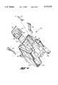
- FIG. 6is a an exploded axonometric view of the switch assembly of the present invention with the button; positioned thereon;
- FIG. 7is an axonometric view of a subassembly of the present invention.
- FIG. 8is an axonometric exploded view of FIG. 7.
- the switch assembly of the present inventionis indicated generally at 10 and includes a housing 12 having preferably a rectangular configuration and having a hollow centrally therethrough as indicated by reference numeral 14. and a mounting flange 17 formed thereon.
- Housing 12has disposed on opposite sides thereof a pair of resiliently deflectable mounting tabs 16, 18 which are adapted to engage the under surface of a panel or mounting structure 19 into which the housing is inserted with the undersurface of housing flange 17 registering on the surface of the panel 19.
- Housing 12has received in the upper end of hollow 14 a switching member subassembly indicated generally at 20; and, in the lower or opposite end of the hollow 14 is received a base indicated generally at 22.
- a latching member in the form a resilient wire latch piece indicated at 23 with a hook 27 formed on the lower end and with the end opposite hook 27 secured in a recess or notch formed in the subassembly 20is disposed to have hook 27 engage and disengage a cardiod cam surface 25 on the base 22 upon user movement of switching subassembly 20 with respect to the base 22.
- a user actuator or pushbutton 24is received over and attached to the upper end of the switching member subassembly 20.
- the pushbutton 24has certain areas of the surface thereof illustrated in dashed outline and denoted by reference numerals 26, 28 formed as lenses or translucent areas which are illuminated as will hereinafter be described.
- the switching member subassembly 20is illustrated in greater detail, although inverted from the illustration in FIG. 1, as having a body 30 which has a hollow portion or receptacle 32 formed in one end thereof and which is preferably rectangular in configuration.
- Body 30has a pair of snap locking tabs extending therefrom on opposite sides thereof as denoted by reference numerals 34, 36.
- the switching member body 30has a plurality of additional spring tabs mounted on the end thereof opposite tabs 34, 36 as denoted by reference numerals 38 through 44; and, these tabs are adapted to engage the undersurface of pushbutton 24 for securing the pushbutton to the body member 30.
- the body 30is molded with plastic strips formed therein by the two-shot molding process which strips have their surface plated with conductive material to form electrical connectors in each of the sockets formed in receptacle 32 denoted by reference numerals 46, 48.
- Each of the sockets 46, 48has inserted therein one end of a wiper contact 50, 52 which makes electrical contact with the conductive strip (not shown) in each of the sockets 46, 48.
- the sockets 58, 60each have the conductive strip therein extending upwardly into one of the lamp receptacles 54, 56 formed in the upper end of the body 30; and, the unshown conductive strips extend into sockets 58, 60 and are adapted to have the leads of a source of illumination (not shown) such as an LED bulb inserted therein.
- a source of illuminationnot shown
- a switching wiper member 62has a plurality of individual wiper fingers formed thereon and extending therefrom as denoted by reference numerals 64 through 70; and, member 62 has a somewhat serpentine configuration in transverse section with one edge thereof frictionally and movably secured between a ledge 72 in body 30 and a tab or extension 74 provided on the inside surface of locking tab 34. If desired a similar wiper assembly may be attached to the inner side of locking tab 36, but has been omitted in the drawings for illustration of the invention in its simplest form and for clarity of illustration.
- base 22has an upper portion 76 which has a generally rectangular configuration and is adapted to be inserted in the receptacle 32 of body 30.
- the upper portion 76 of the base 22has a plurality of electrically conductive strips 78, 80, 82 provided on one face thereof and which are formed by electroplating the second shot strips in a two-shot molding process.
- Each of the strips 78, 80, 82extends downwardly through an enlarged flange portion 84 of base 22 and extends downwardly therefrom to form the surface one of the terminal pins denoted respectively by reference numeral 86, 88, 90.
- similar stripsmay be molded on the opposite face of the upper portion 76 of base 22; and, similarly such unshown strips may extend downwardly to form additional terminal pins.
- the stripsare contacted by one of the wipers 64 through 70 on the wiper member 62 as the switching member 20 is moved slidably within the housing 12; and, the configuration of the strips 78, 80, 82 determines the switching arrangement or logic.
- the base 22is attached to the housing 12 by a plurality of and preferably four spring tabs extending downwardly from the flange portion 84, three of which are illustrated and denoted by reference numerals 92, 94, 96.
- each of the tabsis snap locked against a correspondingly provided surface such as a notch or ledge 108, 110 formed in the hollow 32 of member 30, thus retaining the base securely in the housing 12.
- the basewith the integrally formed terminal pins 86 through 89, 102 through 106 is releasable and readily removable from the housing 12 by compressing tabs 92, 94, 96 with a suitable tool.
- the logic of the switching function of the assembly 10may be changed without the need to retool and replace any other parts of the switch assembly.
- This arrangementenables the switching members subassembly 20 and housing to be used without alteration on multiple switching arrangements, resulting in significant economics of manufacture for a variety of different switching arrangements.
- a plurality of spaced recesses denoted by reference numerals 98, 100are provided in the upper surface of the portion 76 of the base with each of the recesses having on the outboard portion of the inner wall thereof an electrically conductive strip (not shown) formed by the two-shot molding process and subsequent electroplating of the second shot and which is extended downwardly through flange 84 to form a connector pin, one of which is illustrated in FIG. 1 and denoted by reference numeral 102.
- the wipers 50, 52engage respectively the conductive strips in recesses 98, 100.
- the wipers 50, 52thus provide continuous electrical connection between the terminal pins and the lamp sockets 58, 60.
- the userdepresses button 24 and causes the switching member 30 to move downward or deeper into the housing 12 to the position shown in dashed outline in FIGS. 2, 3 and 5 deflecting hooked end 27 of latch wire 23 over cam surface 112 until the hooked end 27 snaps into the detent or notch 25 of the cam surface, whereupon the switching member 30 is latched in the depressed condition shown in dashed outline.
- a subsequent downward or depression movement of the switching member 30 by user pressure on button 24causes the hooked end 27 of latch wire 23 to snap over the apex portion 114 of the cam surface and unlatch, permitting the hooked end of the latch 23 to slide along portion 116 of the cam surface, thereby permitting the switching member to return to its initial or extended position as shown in solid outline FIGS. 2 through 5.
- a return spring 118is provided in the base bore 120 and is operative to bias the subassembly 20 outward.
- the present inventionthus provides a unique and novel push-push button switch assembly having an illuminated pushbutton and an illuminated indicia of the state of switch actuation and which is low in manufacturing cost and assembled easily with a minimum of parts.
Landscapes
- Push-Button Switches (AREA)
Abstract
Description
Claims (13)
Priority Applications (1)
| Application Number | Priority Date | Filing Date | Title |
|---|---|---|---|
| US08/706,543US5727675A (en) | 1996-09-06 | 1996-09-06 | Latching pushbutton switch assembly |
Applications Claiming Priority (1)
| Application Number | Priority Date | Filing Date | Title |
|---|---|---|---|
| US08/706,543US5727675A (en) | 1996-09-06 | 1996-09-06 | Latching pushbutton switch assembly |
Publications (1)
| Publication Number | Publication Date |
|---|---|
| US5727675Atrue US5727675A (en) | 1998-03-17 |
Family
ID=24838071
Family Applications (1)
| Application Number | Title | Priority Date | Filing Date |
|---|---|---|---|
| US08/706,543Expired - Fee RelatedUS5727675A (en) | 1996-09-06 | 1996-09-06 | Latching pushbutton switch assembly |
Country Status (1)
| Country | Link |
|---|---|
| US (1) | US5727675A (en) |
Cited By (24)
| Publication number | Priority date | Publication date | Assignee | Title |
|---|---|---|---|---|
| US6028279A (en)* | 1998-02-27 | 2000-02-22 | Korry Electronics Co. | Lighted push button switch |
| US6218634B1 (en)* | 1999-09-01 | 2001-04-17 | Valeo Electrical Systems, Inc. | Switch with integrated flasher relay |
| KR20010076334A (en)* | 2000-01-21 | 2001-08-11 | 테에르베 오토모티브 일렉트로닉스 운트 콤포넌츠 게엠베하 운트 코. 카게 | Diaphragm switch |
| US20030052513A1 (en)* | 2001-09-04 | 2003-03-20 | Uleski Michael A. | Control panel for a vehicle |
| US6618515B2 (en)* | 2000-06-21 | 2003-09-09 | Mitsubishi Cable Industries, Ltd. | Connector with a connection detection function, optical fiber cable with a connection detection function, and equipment control mechanism for an optical equipment |
| US20040169377A1 (en)* | 2003-02-27 | 2004-09-02 | Nifco Inc. | Latch device |
| US20040222647A1 (en)* | 2003-05-07 | 2004-11-11 | Smith Kelly K. | Low profile mechanical assist hood latch |
| US20050077837A1 (en)* | 2003-01-16 | 2005-04-14 | Surefire, Llc | Brightness controllable flashlights |
| US6957979B2 (en) | 2001-06-01 | 2005-10-25 | Southco, Inc. | Latch with bail-type mounting |
| US6965085B1 (en)* | 2004-11-04 | 2005-11-15 | Illinois Tool Works Inc. | Push-button switch |
| EP1670010A1 (en)* | 2004-12-10 | 2006-06-14 | Societa'Europea Componenti Elletrici S.p.A. | Switch |
| WO2006111021A1 (en)* | 2005-04-22 | 2006-10-26 | Tyco Electronics Canada Ltd. | Sealed soft switch assemblies |
| US20080049949A1 (en)* | 2006-08-18 | 2008-02-28 | Snider Chris R | Lightweight audio system for automotive applications and method |
| US20080110734A1 (en)* | 2006-11-14 | 2008-05-15 | Matsushita Electric Industrial Co., Ltd. | Switch for vehicle |
| US20080237009A1 (en)* | 2007-03-27 | 2008-10-02 | Adam Weisz-Margulescu | Sealed switch assembly |
| US20080283377A1 (en)* | 2007-05-19 | 2008-11-20 | Harris Daren L | Haptics cone |
| CN102522244A (en)* | 2011-12-14 | 2012-06-27 | 黄山市汽车电器股份公司 | Automobile small switch structure |
| CN103107031A (en)* | 2012-12-08 | 2013-05-15 | 重庆示展科技发展中心 | Control panel integrated switch indicator lamp |
| US20130248340A1 (en)* | 2010-12-03 | 2013-09-26 | Eao Holding Ag | Electric SMD Type Switching Element |
| US8760886B2 (en) | 2006-08-18 | 2014-06-24 | Delphi Technologies, Inc. | Lightweight audio system for automotive applications and method |
| US9237685B2 (en) | 2006-08-18 | 2016-01-12 | Delphi Technologies, Inc. | Lightweight audio system for automotive applications and method |
| US9607789B1 (en)* | 2013-12-20 | 2017-03-28 | Delta Systems, Inc. | Switch assembly and method of operating same |
| EP3246252A1 (en)* | 2016-05-17 | 2017-11-22 | ITT Manufacturing Enterprises LLC | Button assembly for seat position control |
| US20240029697A1 (en)* | 2020-12-02 | 2024-01-25 | Goertek Inc. | Sound generating assembly and electronic device having the same |
Citations (5)
| Publication number | Priority date | Publication date | Assignee | Title |
|---|---|---|---|---|
| US4001526A (en)* | 1974-07-12 | 1977-01-04 | Molex Incorporated | Alternate action switch |
| US4549050A (en)* | 1984-06-20 | 1985-10-22 | General Motors Corporation | Illuminated control knob for electric switch |
| US4733028A (en)* | 1987-01-27 | 1988-03-22 | Microdot Inc. | Switch |
| US5221816A (en)* | 1991-09-09 | 1993-06-22 | Delta Systems, Inc. | Plunger switch |
| US5463198A (en)* | 1993-06-15 | 1995-10-31 | Alps Electric Co., Ltd. | Switching device |
- 1996
- 1996-09-06USUS08/706,543patent/US5727675A/ennot_activeExpired - Fee Related
Patent Citations (6)
| Publication number | Priority date | Publication date | Assignee | Title |
|---|---|---|---|---|
| US4001526A (en)* | 1974-07-12 | 1977-01-04 | Molex Incorporated | Alternate action switch |
| US4549050A (en)* | 1984-06-20 | 1985-10-22 | General Motors Corporation | Illuminated control knob for electric switch |
| US4733028A (en)* | 1987-01-27 | 1988-03-22 | Microdot Inc. | Switch |
| US5221816A (en)* | 1991-09-09 | 1993-06-22 | Delta Systems, Inc. | Plunger switch |
| US5528007A (en)* | 1991-09-09 | 1996-06-18 | Delta Systems, Inc. | Plunger switch and method of manufacture |
| US5463198A (en)* | 1993-06-15 | 1995-10-31 | Alps Electric Co., Ltd. | Switching device |
Cited By (68)
| Publication number | Priority date | Publication date | Assignee | Title |
|---|---|---|---|---|
| US6028279A (en)* | 1998-02-27 | 2000-02-22 | Korry Electronics Co. | Lighted push button switch |
| US6218634B1 (en)* | 1999-09-01 | 2001-04-17 | Valeo Electrical Systems, Inc. | Switch with integrated flasher relay |
| KR20010076334A (en)* | 2000-01-21 | 2001-08-11 | 테에르베 오토모티브 일렉트로닉스 운트 콤포넌츠 게엠베하 운트 코. 카게 | Diaphragm switch |
| US6333478B1 (en)* | 2000-01-21 | 2001-12-25 | Trw Automoitve Electronics & Components Gmbh & Co. Kg | Diaphragm switch |
| EP1119008A3 (en)* | 2000-01-21 | 2003-08-06 | TRW Automotive Electronics & Components GmbH & Co. KG | Membrane switch |
| US6618515B2 (en)* | 2000-06-21 | 2003-09-09 | Mitsubishi Cable Industries, Ltd. | Connector with a connection detection function, optical fiber cable with a connection detection function, and equipment control mechanism for an optical equipment |
| US6957979B2 (en) | 2001-06-01 | 2005-10-25 | Southco, Inc. | Latch with bail-type mounting |
| US20030052513A1 (en)* | 2001-09-04 | 2003-03-20 | Uleski Michael A. | Control panel for a vehicle |
| US6820921B2 (en)* | 2001-09-04 | 2004-11-23 | Lear Corporation | Control panel for a vehicle |
| US20050077837A1 (en)* | 2003-01-16 | 2005-04-14 | Surefire, Llc | Brightness controllable flashlights |
| US7116061B2 (en) | 2003-01-16 | 2006-10-03 | Surefire, Llc | Brightness controllable flashlights |
| US20040169377A1 (en)* | 2003-02-27 | 2004-09-02 | Nifco Inc. | Latch device |
| US6986535B2 (en)* | 2003-02-27 | 2006-01-17 | Nifco Inc. | Latch device |
| US20040222647A1 (en)* | 2003-05-07 | 2004-11-11 | Smith Kelly K. | Low profile mechanical assist hood latch |
| US7325846B2 (en) | 2003-05-07 | 2008-02-05 | Hewlett-Packard Development Company, L.P. | Low profile mechanical assist hood latch |
| US7614672B2 (en) | 2003-05-07 | 2009-11-10 | Hewlett-Packard Development Company, L.P. | Low profile mechanical assist hood latch |
| US20080061563A1 (en)* | 2003-05-07 | 2008-03-13 | Hewlett-Packard Development Company, L.P. | Low profile mechanical assist hood latch |
| US6965085B1 (en)* | 2004-11-04 | 2005-11-15 | Illinois Tool Works Inc. | Push-button switch |
| EP1670010A1 (en)* | 2004-12-10 | 2006-06-14 | Societa'Europea Componenti Elletrici S.p.A. | Switch |
| US20060131149A1 (en)* | 2004-12-10 | 2006-06-22 | Societa' Europea Componenti Elettrici S.P.A. In Short S.E.C.E. S.P.A. | Switch |
| US7217897B2 (en)* | 2004-12-10 | 2007-05-15 | Scoieta′ Europea Componenti Elettrici S.p.A. In Short S.E.C.E. S.p.A. | Backpanel insertion switch |
| WO2006111021A1 (en)* | 2005-04-22 | 2006-10-26 | Tyco Electronics Canada Ltd. | Sealed soft switch assemblies |
| US20060237295A1 (en)* | 2005-04-22 | 2006-10-26 | Tyco Electronics Canada Ltd. | Sealed soft switch assemblies |
| US7173206B2 (en) | 2005-04-22 | 2007-02-06 | Tyco Electronics Canada Ltd. | Sealed soft switch assemblies |
| US8087165B2 (en) | 2006-08-18 | 2012-01-03 | Delphi Technologies, Inc. | Lightweight audio system for automotive applications and method |
| US8988884B2 (en) | 2006-08-18 | 2015-03-24 | Delphi Technologies, Inc | Lightweight audio system for automotive applications and method |
| US9237683B2 (en) | 2006-08-18 | 2016-01-12 | Delphi Technologies, Inc. | Lightweight audio system for automotive applications and method |
| US9237685B2 (en) | 2006-08-18 | 2016-01-12 | Delphi Technologies, Inc. | Lightweight audio system for automotive applications and method |
| US9173332B2 (en) | 2006-08-18 | 2015-10-27 | Delphi Technologies, Inc. | Lightweight audio system for automotive applications and method |
| US9119288B2 (en) | 2006-08-18 | 2015-08-25 | Delphi Technologies, Inc. | Lightweight audio system for automotive applications and method |
| US7733659B2 (en) | 2006-08-18 | 2010-06-08 | Delphi Technologies, Inc. | Lightweight audio system for automotive applications and method |
| US20100186217A1 (en)* | 2006-08-18 | 2010-07-29 | Delphi Technologies, Inc. | Lightweight audio system for automotive applications and method |
| US20100205622A1 (en)* | 2006-08-18 | 2010-08-12 | Snider Chris R | Lightweight audio system for automotive applications and method |
| US8035976B2 (en) | 2006-08-18 | 2011-10-11 | Delphi Technologies, Inc. | Lightweight audio system for automotive applications and method |
| US20080049949A1 (en)* | 2006-08-18 | 2008-02-28 | Snider Chris R | Lightweight audio system for automotive applications and method |
| US9013881B2 (en) | 2006-08-18 | 2015-04-21 | Delphi Technologies, Inc. | Lightweight audio system for automotive applications and method |
| US8284559B2 (en) | 2006-08-18 | 2012-10-09 | Delphi Technologies, Inc. | Lightweight audio system for automotive applications and method |
| US8982561B2 (en) | 2006-08-18 | 2015-03-17 | Delphi Technologies, Inc. | Lightweight audio system for automotive applications and method |
| US8477509B2 (en) | 2006-08-18 | 2013-07-02 | Delphi Technologies, Inc. | Lightweight audio system for automotive applications and method |
| US8493739B2 (en) | 2006-08-18 | 2013-07-23 | Delphi Technologies, Inc. | Lightweight audio system for automotive applications and method |
| US8498126B2 (en) | 2006-08-18 | 2013-07-30 | Delphi Technologies, Inc. | Lightweight audio system for automotive applications and method |
| US8947860B2 (en) | 2006-08-18 | 2015-02-03 | Delphi Technologies, Inc. | Lightweight audio system for automotive applications and method |
| US8570757B2 (en) | 2006-08-18 | 2013-10-29 | Delphi Technologies, Inc. | Lightweight audio system for automotive applications and method |
| US8593821B2 (en) | 2006-08-18 | 2013-11-26 | Delphi Technologies, Inc. | Lightweight audio system for automotive applications and method |
| US8599568B2 (en) | 2006-08-18 | 2013-12-03 | Delphi Technologies, Inc. | Lightweight audio system for automotive applications and method |
| US8625293B2 (en) | 2006-08-18 | 2014-01-07 | Delphi Technologies, Inc. | Lightweight audio system for automotive applications and method |
| US8625292B2 (en) | 2006-08-18 | 2014-01-07 | Delphi Technologies, Inc. | Lightweight audio system for automotive applications and method |
| US8724335B2 (en) | 2006-08-18 | 2014-05-13 | Delphi Technologies, Inc. | Lightweight audio system for automotive applications and method |
| US8731862B2 (en) | 2006-08-18 | 2014-05-20 | Delphi Technologies, Inc. | Lightweight audio system for automotive applications and method |
| US8749988B2 (en) | 2006-08-18 | 2014-06-10 | Delphi Technologies, Inc. | Lightweight audio system for automotive applications and method |
| US8760886B2 (en) | 2006-08-18 | 2014-06-24 | Delphi Technologies, Inc. | Lightweight audio system for automotive applications and method |
| US8830687B2 (en) | 2006-08-18 | 2014-09-09 | Delphi Technologies, Inc. | Lightweight audio system for automotive applications and method |
| CN102510288B (en)* | 2006-08-18 | 2014-10-22 | 德尔菲技术公司 | Audio system for vehicle |
| US7579568B2 (en)* | 2006-11-14 | 2009-08-25 | Panasonic Corporation | Switch for vehicle |
| US20080110734A1 (en)* | 2006-11-14 | 2008-05-15 | Matsushita Electric Industrial Co., Ltd. | Switch for vehicle |
| US20080237009A1 (en)* | 2007-03-27 | 2008-10-02 | Adam Weisz-Margulescu | Sealed switch assembly |
| US20080283377A1 (en)* | 2007-05-19 | 2008-11-20 | Harris Daren L | Haptics cone |
| US7723626B2 (en)* | 2007-05-19 | 2010-05-25 | Visteon Global Technologies, Inc. | Haptics cone |
| US20130248340A1 (en)* | 2010-12-03 | 2013-09-26 | Eao Holding Ag | Electric SMD Type Switching Element |
| CN102522244A (en)* | 2011-12-14 | 2012-06-27 | 黄山市汽车电器股份公司 | Automobile small switch structure |
| CN103107031B (en)* | 2012-12-08 | 2015-04-01 | 重庆示展科技发展中心 | Control panel integrated switch indicator lamp |
| CN103107031A (en)* | 2012-12-08 | 2013-05-15 | 重庆示展科技发展中心 | Control panel integrated switch indicator lamp |
| US9607789B1 (en)* | 2013-12-20 | 2017-03-28 | Delta Systems, Inc. | Switch assembly and method of operating same |
| EP3246252A1 (en)* | 2016-05-17 | 2017-11-22 | ITT Manufacturing Enterprises LLC | Button assembly for seat position control |
| US10173778B2 (en) | 2016-05-17 | 2019-01-08 | Itt Manufacturing Enterprises Llc | Button assembly for seat position control |
| US10829223B2 (en) | 2016-05-17 | 2020-11-10 | Itt Manufacturing Enterprises Llc | Button assembly for seat position control |
| US20240029697A1 (en)* | 2020-12-02 | 2024-01-25 | Goertek Inc. | Sound generating assembly and electronic device having the same |
| US12334046B2 (en)* | 2020-12-02 | 2025-06-17 | Goertek Inc. | Sound generating assembly and electronic device having the same |
Similar Documents
| Publication | Publication Date | Title |
|---|---|---|
| US5727675A (en) | Latching pushbutton switch assembly | |
| US3927290A (en) | Selectively illuminated pushbutton switch | |
| US7554047B2 (en) | Lighted pushbutton-type switch assembly | |
| US5107082A (en) | Dual lighted rocker switch embodying a printed circuit board | |
| US5359165A (en) | Illuminated rotary switch assembly | |
| US7514643B1 (en) | Lighted pushbutton switch assembly | |
| US5584380A (en) | Seesaw switch | |
| JP4248563B2 (en) | Push switch | |
| US4665290A (en) | Trigger operated portable electric tool switch | |
| CA1320521C (en) | Lamp with an integral switch | |
| US5320547A (en) | Lamp socket for a fluorescent lamp | |
| US6388220B1 (en) | Illuminated switching device for stabilized illumination to translucent portion of knob | |
| US7063447B2 (en) | Illuminating device for a cigar lighter or multi-function electric socket | |
| US4504713A (en) | Push button electrical switch assembly | |
| US20140369057A1 (en) | Illuminating unit | |
| US5821490A (en) | Push button switch module | |
| US7022931B2 (en) | Slide switch assemblies | |
| US4698471A (en) | Trigger operated portable electric tool switch | |
| US20050263380A1 (en) | Switch with light supported in operating member | |
| WO2005006367A1 (en) | Electronic device remote control keypad back lighting light pipe | |
| US4749832A (en) | Illuminated push button switch module | |
| CN113451064A (en) | Push-button switch | |
| US4285033A (en) | Lampholder--switch module | |
| US5041703A (en) | Mirror control switch for automotive vehicles | |
| CN212783164U (en) | Movable button |
Legal Events
| Date | Code | Title | Description |
|---|---|---|---|
| AS | Assignment | Owner name:EATON CORPORATON, OHIO Free format text:ASSIGNMENT OF ASSIGNORS INTEREST;ASSIGNORS:LEVEQUE, DENIS J.;LARSEN, MICHAEL R.;REEL/FRAME:008151/0348 Effective date:19960904 | |
| FEPP | Fee payment procedure | Free format text:PAYOR NUMBER ASSIGNED (ORIGINAL EVENT CODE: ASPN); ENTITY STATUS OF PATENT OWNER: LARGE ENTITY | |
| AS | Assignment | Owner name:MDH COMPANY, INC., OHIO Free format text:ASSIGNMENT OF ASSIGNORS INTEREST;ASSIGNOR:EATON CORPORATION;REEL/FRAME:011149/0172 Effective date:20000905 | |
| REMI | Maintenance fee reminder mailed | ||
| AS | Assignment | Owner name:DELPHI TECHNOLOGIES, INC., MICHIGAN Free format text:ASSIGNMENT OF ASSIGNORS INTEREST;ASSIGNOR:MDH COMPANY, INC., A CORP. DELAWARE;REEL/FRAME:012475/0170 Effective date:20011106 | |
| FPAY | Fee payment | Year of fee payment:4 | |
| SULP | Surcharge for late payment | ||
| REMI | Maintenance fee reminder mailed | ||
| LAPS | Lapse for failure to pay maintenance fees | ||
| LAPS | Lapse for failure to pay maintenance fees | Free format text:PATENT EXPIRED FOR FAILURE TO PAY MAINTENANCE FEES (ORIGINAL EVENT CODE: EXP.); ENTITY STATUS OF PATENT OWNER: LARGE ENTITY | |
| STCH | Information on status: patent discontinuation | Free format text:PATENT EXPIRED DUE TO NONPAYMENT OF MAINTENANCE FEES UNDER 37 CFR 1.362 | |
| FP | Lapsed due to failure to pay maintenance fee | Effective date:20060317 |