US5727449A - Automatic basting roaster - Google Patents
Automatic basting roasterDownload PDFInfo
- Publication number
- US5727449A US5727449AUS08/800,135US80013597AUS5727449AUS 5727449 AUS5727449 AUS 5727449AUS 80013597 AUS80013597 AUS 80013597AUS 5727449 AUS5727449 AUS 5727449A
- Authority
- US
- United States
- Prior art keywords
- pan
- roaster
- basting
- roasting
- wall
- Prior art date
- Legal status (The legal status is an assumption and is not a legal conclusion. Google has not performed a legal analysis and makes no representation as to the accuracy of the status listed.)
- Expired - Fee Related
Links
- 239000007788liquidSubstances0.000claimsabstractdescription44
- 230000002093peripheral effectEffects0.000claimsdescription10
- 238000007789sealingMethods0.000claimsdescription3
- 239000012530fluidSubstances0.000abstractdescription9
- 238000005325percolationMethods0.000description6
- 238000009835boilingMethods0.000description5
- 238000004140cleaningMethods0.000description3
- 238000001704evaporationMethods0.000description3
- 230000008020evaporationEffects0.000description3
- 239000000463materialSubstances0.000description3
- 229910000831SteelInorganic materials0.000description1
- 230000001351cycling effectEffects0.000description1
- 235000011389fruit/vegetable juiceNutrition0.000description1
- 238000009413insulationMethods0.000description1
- 239000002184metalSubstances0.000description1
- 238000000034methodMethods0.000description1
- 229920001296polysiloxanePolymers0.000description1
- 230000000284resting effectEffects0.000description1
- 239000010959steelSubstances0.000description1
Images


Classifications
- A—HUMAN NECESSITIES
- A47—FURNITURE; DOMESTIC ARTICLES OR APPLIANCES; COFFEE MILLS; SPICE MILLS; SUCTION CLEANERS IN GENERAL
- A47J—KITCHEN EQUIPMENT; COFFEE MILLS; SPICE MILLS; APPARATUS FOR MAKING BEVERAGES
- A47J37/00—Baking; Roasting; Grilling; Frying
- A47J37/10—Frying pans, e.g. frying pans with integrated lids or basting devices
- A47J37/106—Integrated basting devices
- A—HUMAN NECESSITIES
- A47—FURNITURE; DOMESTIC ARTICLES OR APPLIANCES; COFFEE MILLS; SPICE MILLS; SUCTION CLEANERS IN GENERAL
- A47J—KITCHEN EQUIPMENT; COFFEE MILLS; SPICE MILLS; APPARATUS FOR MAKING BEVERAGES
- A47J36/00—Parts, details or accessories of cooking-vessels
- A47J36/16—Inserts
Definitions
- the inventionrelates to roasting; and, more particularly, to automatically basting roasters.
- an automatic basting roasterincluding a main roasting pan, a basting pan disposed in the roasting pan, and a rack holding a roast removable mounted on the basting pan.
- a drip panis supported above the rack and the area in the roasting pan between the basting pan and the bottom of the roasting pan acts as a basting fluid supply chamber sealed off from the atmosphere except for tubing extending into the liquid therein opening at one end a short distance above the bottom of the roasting pan and opening at the other end above and onto the top of the drip pan.
- the basting fluid supply chamber at the bottom of the roasting panis valve controlled so that, when the valve is open and the chamber fills with liquid from the basting pan reservoir formed between the rack and the basting pan, the liquid rises above the open bottom of the tubing forming a trap which liquid rises in the chamber until the valve closes.
- the liquid in the chamberwhich is below boiling, begins to heat up forming pressure therein (since the heated liquid can't evaporate due to the chamber being sealed) generating steam which pushes liquid in the chamber up the tubing and out over the top of the drip pan.
- This liquiddrips down over the roast basting the same and dripping back into the basting pan reservoir. This continues until the liquid level in the chamber reaches the open bottom of the tubing at which point the pressure of the steam above the liquid in the chamber escapes up the tubing until the pressure in the chamber drops and the valve opens. The cycle is then repeated.
- FIG. 1is a perspective view illustrating use of the roaster of the invention
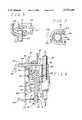
- FIG. 2is an elevational view, partly in section, illustrating a closed position of the valve of the roaster of FIG. 1;
- FIG. 3is an assembled view, partly in section, of the roaster alone of FIG. 1;
- FIG. 4is a view similar to FIG. 2 illustrating an open position of the valve
- FIG. 5is a view taken along line 5 of FIG. 3;
- FIG. 6is a view taken along line 6 of FIG. 3;
- FIG. 7is a view taken along lines 7--7 of FIG. 6;
- FIG. 8is a view similar to FIG. 6 showing an alternate position thereof;
- FIG. 9is a view taken along line 9 of FIG. 3;
- FIG. 10is a view taken along lines 10--10 of FIG. 8;
- FIG. 11is an exploded view of the roaster alone of FIG. 1;
- FIG. 12is a perspective view of an accessory to be used with the roaster of FIG. 1;
- FIG. 13is a view taken along lines 13--13 of FIG. 12;
- FIG. 14is a view similar to FIG. 12 showing movement of the parts thereof;
- FIG. 15is a view taken along lines 15--15 of FIG. 14;
- FIG. 16is a view taken along lines 16--16 of FIG. 11;
- FIG. 17is a view similar to FIG. 6 illustrating opening of the latch thereof.
- roaster 10is shown about to be placed in oven 11.
- Roaster 10is shown in exploded view in FIG. 11.
- Roaster 10thus includes a main roasting pan 12 which is adapted to receive therein a basting pan 13 (see also FIG. 3).
- a rack 14(FIG. 11) is mounted inside of pan 12 on top of pan 12 as seen in FIG. 3.
- rack 14has an elongated oval-shaped main body portion 15 in the form a grid providing by a plurality of spaced rods 16. Two of these rods, such as rods 15', 15", have downwardly extending generally V-shaped portions 17 for supporting rack 14 inside of basting pan 13 and spacing the same from the bottom wall 18 thereof as seen in FIG. 3.
- Rack 14also has a pair of spaced handles 19, 20 extending upwardly from main body portion 15 and providing a support for a drip pan 21 (see also FIG. 11) adapted to rest on top of the curved integral bail portions 22, 23 of handles 19, 20, respectively, as seen in FIG. 3. Finally, roaster 10 is closed off by a top cover 24 (see also FIG. 11).
- Roasting pan 12has a pair of integral carrying handles 25, 26 (see also FIG. 3) extending outwardly from the side wall 27 thereof and a pair of latch members 28, 29 integral with side wall 27 of pan 12 and extending outwardly therefrom above handles 25, 26, respectively.
- each latch membersuch as latch member 28, is pivotally connected via pivot rod 30 to flange 31 integral with side wall 27 of roasting pan 12. That is, member 28 pivots about points 32, 33 (see also FIG. 17) to selectively move the same into engagement with latch portion 34 of bracket 76 mounted to basting pan 13.
- the upper rim 36 of roasting pan 12is curved in cross-section.
- the lip or rim 35 of basting pan 13rests on top of the lip or rim 36 of pan 12 so that the bottom wall 18 of pan 13 is spaced from the bottom wall 37 of pan 12 a predetermined distance as seen in FIG. 3.
- each tube 38, 39extends through spaced openings 40, 41, respectively, in bottom wall 18 of pan 13.
- An apertured resilient seal 42(see FIG. 9) is mounted in each opening 40, 41 for sealing the respective tube 38 or 39 therein.
- each tube 38, 39terminates at its lower end a short distance above bottom wall 37 of pan 12 for reasons to be discussed.
- each tube 38, 39extends through a U-shaped member 42 (see also FIG. 7) integral with the handle 43 of valve member 44 (FIG. 6).
- a like configured resilient sleeve 45(see also FIG. 7) abuts against the interior of member 42 and against tube 38 as seen in FIGS. 6 and 7.
- Each tube 38, 39has an opening 46 (see FIG. 6) therethrough for reasons to be discussed.
- Drip pan 21(FIG. 11) has a pair of spaced openings 47, 48 therethrough for receiving the upper ends of the tubes 38, 39 therethrough (see FIG. 3).
- each opening 47, 48has a resilient diverter 49 mounted thereon having an opening 50 through which the upper end of each tube, such as tube 38, extends and fits therein, the terminal end opening into a slot 51 formed in diverter 49 for directing or diverting fluids in the direction of arrow 52.
- the drip pan 21includes a generally oval-shaped main body portion 53 surrounded by a peripheral upstanding rim 54. Body portion 53 includes a plurality of spaced lowered portions 55 (see FIG. 16) of varying configurations and dimensions. The entire pan 21 includes a plurality of small spaced orifices 56 therethrough. As seen in FIG. 3, drip pan 21 rests on top of bail portions 22, 23 of handles 19, 20, respectively.
- Cover 24(FIG. 11) includes a main body portion 57 having a peripheral integral side wall 58 and an outwardly extending peripheral rim 59.
- a notch 60is provided on each side of rim 59 for receiving member 34 therethrough.
- a pair of spaced handles 61, 62(see FIG. 3) are provided on wall 58.
- Valving means 63is provided inside of basting pan 13 centrally located in the bottom wall 18 thereof.
- Valving means 63includes a main body portion 64 (FIG. 2) forming a housing open at top and bottom. That is, the main body portion 64 is integral with bottom wall 18, the opening 65 therethrough providing the open top of main body portion 64.
- An elongated pin 66extends through aligned holes 67, 68 in main body portion 64 having an enlarged head 69 for grasping the same. In this manner, pin 66 may be pulled out of holes 67, 68 to provide access to the interior of main body portion 64 to remove floating valve 70 therefrom for cleaning.
- Valve 70has a main lower body portion 71 and an integral upper body portion 72 of lesser diameter than main body portion 71.
- a resilient O-ring 73is provided encircling upper body portion 72. Both body portions 71, 72 may be round in cross-section.
- a removable filter mesh screen 74 of any suitable filter materialis secured to wall 18 closing off opening 65.
- a resilient peripheral seal member 75extends about rim 35 thereby disposed between rim 36 of roasting pan 12 and rim 35 of basting pan 13.
- Bracket 76is mounted to the inner wall 77 of basting pan 13 overlying rim 35 of pan 13 and rim 36 of pan 12.
- Rim 59 of cover 24thus rests on top of the upper latch portion 34 of bracket 76.
- Latch member 28thus pivots from the open position of FIG. 17 to the lock position of FIG. 6. That is, pushing in on extension portion 79 of latch member 28 in the direction of arrow 80 pivots the same about points 32, 33 and raises latch member 28 and moves upper latch portion 81 of latch member 28 opposite the direction of arrow 80 (FIG. 6) as seen in FIG. 17 thereby releasing latch member 28 from engagement with latch portion 34.
- latch member 28latches to latch portion 34.
- valve handle 43is integral with valve member 44 which terminates in a downwardly extending portion 83 for easy in grasping the same.
- Valve member 44slides within flange 78 so that, by pushing inwardly, members 42, 45 are moved from the FIG. 10 position to the FIG. 7 position.
- Thisselectively opens and closes opening 46 in tubes 38, 39 via engagement and disengagement of resilient member 45 for reasons to be discussed.
- a pair of elongated notches 84, 85are provided on opposite sides of member 84 so that tube 38, in FIG. 7, may move to the notched position shown in FIG. 10.
- the food desired to be roastedsuch as turkey 86 in FIG. 3, is placed on top of rack 15, drip pan 21 is placed on top of the rack 15, the cover 24 is placed on top of basting pan 13 nestling in pan 12, and the latch member 28 is latched.
- Tubes 38, 39may be about 10" in height. Steam goes up the tubes and pressure within the area below pan 13 and above wall 37 drops down to zero. Valve 70 now opens (FIG. 4). The liquid therein never reaches boiling (it may go to about 99° C.). The liquid again is heated up raising valve 70 closing off the opening 65 and again creating steam that rises in tubes 38, 39. This cycle takes place about every 5 to 10 minutes. About one to two liters of liquid is carried up along with the steam each time the steam rises in tubes 38, 39. This ejects the liquid in the direction of arrow 52 in FIG. 5 across drip pan 21 allowing the liquid to percolate down through perforations 56 thereby basting the turkey.
- pan 21aid in resisting warpage of pan 21 due to the heat being generated and cut down the area in which liquid flows down over the turkey. As the liquid collects in portions 55 and begins to come in faster moving to the higher level of pan 21, there is always a full pattern of liquid disposed over the turkey.
- valve 44When one pushes in on valve 44, hole 46 is sealed since tube 38 is in the FIG. 7 position. All the liquid goes up tubes 38, 39 to pan 21 and begins dripping. However, when valve 44 is pulled back, e.g., about 1/8", thereby opening hole 46 (see FIG. 10), basting is stopped. The cycling is continued but the liquid stays in the basting pan 13 and is not carried up to the drip pan 21. This enables one to brown the roast, if desired.
- Tubes 38, 39may be of steel.
- Valve 70may be of any suitable material.
- Rack 14allows one to lift the roast out of the pan 13 and acts as a balance for the drip pan 21.
- the baffle pan 100 shown in FIGS. 12 to 15may be used.
- Pan 12 of FIG. 11is adapted to sit inside of pan 100.
- Pan 100has a planar bottom wall 101 surrounded by an upstanding peripheral wall 102.
- Wall 102has a plurality of spaced rectangularly shaped openings therethrough.
- the wall 102has three plies, an outer and inner ply 104, 105, respectively, of metal or the like, sandwiching therebetween an insulating layer 106. Opening 103 is actually three aligned openings through plies 104, 105 and layer 106.
- a lever 107extends through slot 108 in outer wall or ply 104 and is connected to layer 106. When lever 107 is moved to the FIG. 14 position, layer 106 connected thereto moves closing off opening 103. Of course, any intermediate position may be used.
- a plurality of spaced raised protuberances 109are provided on bottom wall 101 to space the bottom wall 37 of pan 12 therefrom when resting thereon.
- Support legs 110(FIG. 3) may also be provided underneath bottom wall 101 at spaced locations.
- Bottom wall 101may also have a plurality of openings, such as openings 111 (FIG. 12) therethrough with a rotatable wheel 112, having a like plurality of like configured openings 114 mounted via pivot pin 113 to bottom wall 101.
- openings 111may be selectively opened or closed (partially or totally) as seen in FIG. 15. Completely closing the openings would stop basting completely. Partially opening the openings can control the basting cycle from about 5 to 20 minutes.
- the overall height of supports 109may be varied to space pan 12 from pan 102. This allows room for the air to circulate.
- the tubes 38, 39are removable for cleaning. Pin 66 can be removed to remove valve 70 for cleaning.
- the bottom of the roasting pan 12acts as a basting fluid supply chamber sealed off from the atmosphere except for tubes 38, 39.
- These tubes 38, 39extend down into the liquid 87 in pan 12 opening a short distance, e.g., 1/16" or less, above the bottom of pan 12.
- Tubes 38, 39open at top on to drip pan 21.
- the chamber in pan 12 below pan 13 and above bottom wall 37 of pan 12is valve controlled by valve 63 when the valve 63 is open and the chamber fills with liquid 87 from the basting pan reservoir formed between the rack 21 and the basting pan 13.
- the liquid 87rises above the open bottom of the tubes 38, 39 forming a trap, which liquid rises in the chamber until the valve 63 closes.
- the liquid 87 in the chamberbegins to heat up forming pressure therein (since it can't evaporate due to the chamber being sealed) generating steam which pushes the liquid 87 in the chamber up the tubes 38, 39 and out over the top of the drip pan 21.
- This liquiddrips down over the roast basting the same and drips back into the reservoir of basting pan 13.
- the liquid level of liquid 87 in the basting fluid supply chamberreaches the open bottom of the tubes 38, 39 at which point the pressure of the steam above the liquid 87 in the basting fluid supply chamber escapes up the tubes 38, 39 until the pressure in the chamber between the bottom of pan 13 and bottom wall 37 of pan 12 drops and the valve 63 opens. The cycle is then repeated.
- Filter 74keeps the juices strained and clean and prevents clogging of valve 63.
- An oven temperature of 350° F. to 400° F.is preferably maintained and, at these temperatures, the liquid 87 reaches a temperature of about 205° F. to 208° F. (below boiling). If desired, insulation may be sprayed on the underside of basting pan 13.
Landscapes
- Engineering & Computer Science (AREA)
- Food Science & Technology (AREA)
- Baking, Grill, Roasting (AREA)
- Cookers (AREA)
- Micro-Organisms Or Cultivation Processes Thereof (AREA)
- Medicines Containing Plant Substances (AREA)
- Frying-Pans Or Fryers (AREA)
- Beans For Foods Or Fodder (AREA)
- General Preparation And Processing Of Foods (AREA)
Abstract
Description
Claims (13)
Priority Applications (12)
| Application Number | Priority Date | Filing Date | Title |
|---|---|---|---|
| US08/800,135US5727449A (en) | 1997-02-13 | 1997-02-13 | Automatic basting roaster |
| AU59627/98AAU760851B2 (en) | 1997-02-13 | 1998-01-21 | Automatic basting roaster |
| PCT/US1998/001148WO1998035596A1 (en) | 1997-02-13 | 1998-01-21 | Automatic basting roaster |
| JP2000600468AJP2002538858A (en) | 1997-02-13 | 1998-01-21 | Automatic basting roaster |
| ES98902828TES2231957T3 (en) | 1997-02-13 | 1998-01-21 | AUTOMATIC SPRAY GRILL. |
| CN98813803ACN1116004C (en) | 1997-02-13 | 1998-01-21 | Automatic Grease Oven |
| EP98902828AEP1056380B1 (en) | 1997-02-13 | 1998-01-21 | Automatic basting roaster |
| AT98902828TATE279138T1 (en) | 1997-02-13 | 1998-01-21 | FRYING DEVICE WITH AUTOMATIC BASING DEVICE |
| DK98902828TDK1056380T3 (en) | 1997-02-13 | 1998-01-21 | Automatic drip frying device |
| HK01106956.8AHK1035998B (en) | 1998-01-21 | Automatic basting roaster | |
| DE69827044TDE69827044T2 (en) | 1997-02-13 | 1998-01-21 | BREAD WITH AUTOMATIC BEGITING DEVICE |
| CA002319226ACA2319226A1 (en) | 1997-02-13 | 1998-01-21 | Automatic basting roaster |
Applications Claiming Priority (1)
| Application Number | Priority Date | Filing Date | Title |
|---|---|---|---|
| US08/800,135US5727449A (en) | 1997-02-13 | 1997-02-13 | Automatic basting roaster |
Publications (1)
| Publication Number | Publication Date |
|---|---|
| US5727449Atrue US5727449A (en) | 1998-03-17 |
Family
ID=25177578
Family Applications (1)
| Application Number | Title | Priority Date | Filing Date |
|---|---|---|---|
| US08/800,135Expired - Fee RelatedUS5727449A (en) | 1997-02-13 | 1997-02-13 | Automatic basting roaster |
Country Status (11)
| Country | Link |
|---|---|
| US (1) | US5727449A (en) |
| EP (1) | EP1056380B1 (en) |
| JP (1) | JP2002538858A (en) |
| CN (1) | CN1116004C (en) |
| AT (1) | ATE279138T1 (en) |
| AU (1) | AU760851B2 (en) |
| CA (1) | CA2319226A1 (en) |
| DE (1) | DE69827044T2 (en) |
| DK (1) | DK1056380T3 (en) |
| ES (1) | ES2231957T3 (en) |
| WO (1) | WO1998035596A1 (en) |
Cited By (10)
| Publication number | Priority date | Publication date | Assignee | Title |
|---|---|---|---|---|
| FR2823963A1 (en)* | 2001-04-30 | 2002-10-31 | Moulinex Sa | Spraying device for food in cooking oven comprises reservoir, located on top of oven arch, and nozzles enabling regulated liquid flow through arch openings |
| US20030015100A1 (en)* | 2001-07-19 | 2003-01-23 | Wrenn Judith H. | Basting apparatus |
| US6582745B1 (en) | 1999-07-09 | 2003-06-24 | Robert Theodore Northern | Self-basting cooking apparatus and method |
| US6588324B1 (en)* | 2002-07-11 | 2003-07-08 | Yitzchak Mor | Device for distributing cooking juices over meat pieces during cooking |
| US20030213375A1 (en)* | 2002-05-17 | 2003-11-20 | Randall Cornfield | Cooking appliance with interconnecting racks |
| US20070272087A1 (en)* | 2006-05-26 | 2007-11-29 | David Carlisle Hull | Basting apparatus |
| US20100275791A1 (en)* | 2007-10-02 | 2010-11-04 | Ken Board | Food Heating Arrangement |
| WO2014161049A1 (en)* | 2013-04-05 | 2014-10-09 | Myoori Pty Ltd | A meat juice recovery apparatus |
| US8881644B1 (en) | 2009-12-21 | 2014-11-11 | II Nicholas J. Scro | Self-basting roasting oven |
| US9451849B2 (en)* | 2015-01-09 | 2016-09-27 | Dominique Howard | Roasting and basting device |
Families Citing this family (2)
| Publication number | Priority date | Publication date | Assignee | Title |
|---|---|---|---|---|
| US10264921B2 (en) | 2015-12-22 | 2019-04-23 | Tuesday Morning Partners, Ltd. | Cookware lid with basting projections |
| USD835453S1 (en) | 2015-12-22 | 2018-12-11 | Tuesday Morning Partners, Ltd. | Cookware basting projections |
Citations (13)
| Publication number | Priority date | Publication date | Assignee | Title |
|---|---|---|---|---|
| US1349302A (en)* | 1919-06-02 | 1920-08-10 | Spitz Charles | Roasting-pan |
| US1700614A (en)* | 1928-01-23 | 1929-01-29 | Joseph C F Moore | Roaster |
| US2142800A (en)* | 1938-03-07 | 1939-01-03 | John H Olexsy | Food baster |
| US2343156A (en)* | 1943-03-03 | 1944-02-29 | Arthur J Penick | Roaster |
| US2350623A (en)* | 1941-09-05 | 1944-06-06 | Charles H Kruea | Combination basting and skewering device |
| US2400405A (en)* | 1943-07-08 | 1946-05-14 | Munny Mfg Company | Automatic basting device |
| US2560605A (en)* | 1948-02-24 | 1951-07-17 | Paul V Shell | Automatic baster |
| US2724323A (en)* | 1950-05-19 | 1955-11-22 | Paul W Hemminger | Automatic basting device |
| US3053166A (en)* | 1951-11-14 | 1962-09-11 | Carrier Corp | Apparatus for blanching food products |
| US3412673A (en)* | 1965-10-22 | 1968-11-26 | Peter H. Landis | Automatic culinary sprinkler apparatus |
| US3922960A (en)* | 1973-11-12 | 1975-12-02 | Sullivan T M | Automatic basting device |
| US4732137A (en)* | 1986-12-04 | 1988-03-22 | Parsons Lee R | Basting apparatus for barbecue grills |
| US5421254A (en)* | 1993-08-18 | 1995-06-06 | Wle Corporation | Stovetop broaster |
Family Cites Families (2)
| Publication number | Priority date | Publication date | Assignee | Title |
|---|---|---|---|---|
| DE237857C (en)* | ||||
| DE339226C (en)* | 1920-05-01 | 1921-07-18 | Anton Hohler | Roast basting device |
- 1997
- 1997-02-13USUS08/800,135patent/US5727449A/ennot_activeExpired - Fee Related
- 1998
- 1998-01-21EPEP98902828Apatent/EP1056380B1/ennot_activeExpired - Lifetime
- 1998-01-21ATAT98902828Tpatent/ATE279138T1/ennot_activeIP Right Cessation
- 1998-01-21AUAU59627/98Apatent/AU760851B2/ennot_activeCeased
- 1998-01-21WOPCT/US1998/001148patent/WO1998035596A1/enactiveIP Right Grant
- 1998-01-21DEDE69827044Tpatent/DE69827044T2/ennot_activeExpired - Fee Related
- 1998-01-21DKDK98902828Tpatent/DK1056380T3/enactive
- 1998-01-21CACA002319226Apatent/CA2319226A1/ennot_activeAbandoned
- 1998-01-21JPJP2000600468Apatent/JP2002538858A/ennot_activeCeased
- 1998-01-21CNCN98813803Apatent/CN1116004C/ennot_activeExpired - Fee Related
- 1998-01-21ESES98902828Tpatent/ES2231957T3/ennot_activeExpired - Lifetime
Patent Citations (13)
| Publication number | Priority date | Publication date | Assignee | Title |
|---|---|---|---|---|
| US1349302A (en)* | 1919-06-02 | 1920-08-10 | Spitz Charles | Roasting-pan |
| US1700614A (en)* | 1928-01-23 | 1929-01-29 | Joseph C F Moore | Roaster |
| US2142800A (en)* | 1938-03-07 | 1939-01-03 | John H Olexsy | Food baster |
| US2350623A (en)* | 1941-09-05 | 1944-06-06 | Charles H Kruea | Combination basting and skewering device |
| US2343156A (en)* | 1943-03-03 | 1944-02-29 | Arthur J Penick | Roaster |
| US2400405A (en)* | 1943-07-08 | 1946-05-14 | Munny Mfg Company | Automatic basting device |
| US2560605A (en)* | 1948-02-24 | 1951-07-17 | Paul V Shell | Automatic baster |
| US2724323A (en)* | 1950-05-19 | 1955-11-22 | Paul W Hemminger | Automatic basting device |
| US3053166A (en)* | 1951-11-14 | 1962-09-11 | Carrier Corp | Apparatus for blanching food products |
| US3412673A (en)* | 1965-10-22 | 1968-11-26 | Peter H. Landis | Automatic culinary sprinkler apparatus |
| US3922960A (en)* | 1973-11-12 | 1975-12-02 | Sullivan T M | Automatic basting device |
| US4732137A (en)* | 1986-12-04 | 1988-03-22 | Parsons Lee R | Basting apparatus for barbecue grills |
| US5421254A (en)* | 1993-08-18 | 1995-06-06 | Wle Corporation | Stovetop broaster |
Cited By (18)
| Publication number | Priority date | Publication date | Assignee | Title |
|---|---|---|---|---|
| US20040009276A1 (en)* | 1999-07-09 | 2004-01-15 | Northern Robert Theodore | Self-basting cooking apparatus and method |
| US6582745B1 (en) | 1999-07-09 | 2003-06-24 | Robert Theodore Northern | Self-basting cooking apparatus and method |
| US6892628B2 (en) | 1999-07-09 | 2005-05-17 | Robert Theodore Northern | Self-basting cooking apparatus and method |
| FR2823963A1 (en)* | 2001-04-30 | 2002-10-31 | Moulinex Sa | Spraying device for food in cooking oven comprises reservoir, located on top of oven arch, and nozzles enabling regulated liquid flow through arch openings |
| US20030015100A1 (en)* | 2001-07-19 | 2003-01-23 | Wrenn Judith H. | Basting apparatus |
| US6766730B2 (en) | 2001-07-19 | 2004-07-27 | Judith H Wrenn | Basting apparatus |
| US6796222B2 (en) | 2002-05-17 | 2004-09-28 | Randall Cornfield | Cooking appliance with interconnecting racks |
| WO2003096854A1 (en)* | 2002-05-17 | 2003-11-27 | 3844374 Canada Inc. | Cooking appliance with interconnecting racks |
| US20030213375A1 (en)* | 2002-05-17 | 2003-11-20 | Randall Cornfield | Cooking appliance with interconnecting racks |
| CN1320871C (en)* | 2002-05-17 | 2007-06-13 | 3844374加拿大公司 | A cooking appliance with interconnected brackets |
| US6588324B1 (en)* | 2002-07-11 | 2003-07-08 | Yitzchak Mor | Device for distributing cooking juices over meat pieces during cooking |
| US20070272087A1 (en)* | 2006-05-26 | 2007-11-29 | David Carlisle Hull | Basting apparatus |
| US7946221B2 (en) | 2006-05-26 | 2011-05-24 | Hull Jr David Carlisle | Basting apparatus |
| US20100275791A1 (en)* | 2007-10-02 | 2010-11-04 | Ken Board | Food Heating Arrangement |
| US8881644B1 (en) | 2009-12-21 | 2014-11-11 | II Nicholas J. Scro | Self-basting roasting oven |
| WO2014161049A1 (en)* | 2013-04-05 | 2014-10-09 | Myoori Pty Ltd | A meat juice recovery apparatus |
| AU2014246672B2 (en)* | 2013-04-05 | 2017-12-07 | Gregory Malcolm Hay | A meat juice recovery apparatus |
| US9451849B2 (en)* | 2015-01-09 | 2016-09-27 | Dominique Howard | Roasting and basting device |
Also Published As
| Publication number | Publication date |
|---|---|
| CN1290143A (en) | 2001-04-04 |
| CN1116004C (en) | 2003-07-30 |
| EP1056380B1 (en) | 2004-10-13 |
| DE69827044D1 (en) | 2004-11-18 |
| AU760851B2 (en) | 2003-05-22 |
| AU5962798A (en) | 1998-09-08 |
| ES2231957T3 (en) | 2005-05-16 |
| EP1056380A4 (en) | 2001-04-04 |
| CA2319226A1 (en) | 1998-08-20 |
| DE69827044T2 (en) | 2006-03-09 |
| JP2002538858A (en) | 2002-11-19 |
| EP1056380A1 (en) | 2000-12-06 |
| WO1998035596A1 (en) | 1998-08-20 |
| HK1035998A1 (en) | 2001-12-21 |
| ATE279138T1 (en) | 2004-10-15 |
| DK1056380T3 (en) | 2004-12-13 |
Similar Documents
| Publication | Publication Date | Title |
|---|---|---|
| US5727449A (en) | Automatic basting roaster | |
| US8067716B1 (en) | Cooking apparatus | |
| CA1295360C (en) | Food treatment cabinet with flash steamer | |
| US9730542B2 (en) | Liquid movement and control within a rotatable container for food preparation | |
| CA2523451C (en) | Multi-purpose stovetop grilling and cooking device | |
| US10499770B2 (en) | Electric fryer | |
| MX2014001591A (en) | Food movement and control within a container for food preparation. | |
| US7228792B2 (en) | Cooker with latching drip tray for selectively opening and closing grease dispensing apertures in cooking pan | |
| AU2003223793B2 (en) | Apparatus for cooking and dispensing food products | |
| DE2623946C3 (en) | Circulating air heating, baking and frying device | |
| US3463078A (en) | Deep fat frying apparatus | |
| DE102021201947A1 (en) | Evaporator for household steamer and household steamer with steam treatment drawer | |
| US3483815A (en) | Food fryer | |
| GB2266654A (en) | Cooking apparatus comprising condenser to remove cooking smells | |
| KR101001614B1 (en) | Cooking vessel using steam | |
| JP3080296U (en) | Multi-purpose fryer | |
| JP3779659B2 (en) | Cooking pot | |
| KR200170543Y1 (en) | Roaster divice | |
| CA2963647C (en) | Electric fryer | |
| KR970002115Y1 (en) | Cooker for roaster | |
| HK1035998B (en) | Automatic basting roaster | |
| KR200291369Y1 (en) | Skewer roaster | |
| JPH0625227Y2 (en) | Dashi stock removal device | |
| JPH1176062A (en) | Food steamer | |
| KR20050120586A (en) | Electric barbecue equipment |
Legal Events
| Date | Code | Title | Description |
|---|---|---|---|
| AS | Assignment | Owner name:HELMAN, BARRY, CALIFORNIA Free format text:ASSIGNMENT OF ASSIGNORS INTEREST;ASSIGNORS:HEALY, JACK;BOND, GREGG A.;REEL/FRAME:009245/0915 Effective date:19980603 Owner name:HELMAN, ANDY, CALIFORNIA Free format text:ASSIGNMENT OF ASSIGNORS INTEREST;ASSIGNORS:HEALY, JACK;BOND, GREGG A.;REEL/FRAME:009245/0915 Effective date:19980603 | |
| AS | Assignment | Owner name:HELMAN, ANDY, CALIFORNIA Free format text:ASSIGNMENT OF ASSIGNORS INTEREST;ASSIGNOR:HEALY, JACK;REEL/FRAME:009500/0246 Effective date:19980603 Owner name:HELMAN, BARRY, CALIFORNIA Free format text:ASSIGNMENT OF ASSIGNORS INTEREST;ASSIGNOR:HEALY, JACK;REEL/FRAME:009500/0246 Effective date:19980603 | |
| AS | Assignment | Owner name:WIBISONO, ALI SUGIHARTO, INDONESIA Free format text:ASSIGNMENT OF ASSIGNORS INTEREST;ASSIGNOR:HEALY, JACK;REEL/FRAME:010499/0915 Effective date:19991223 | |
| REMI | Maintenance fee reminder mailed | ||
| FPAY | Fee payment | Year of fee payment:4 | |
| SULP | Surcharge for late payment | ||
| AS | Assignment | Owner name:ALI SUGIHARTO WIBISONO, INDONESIA Free format text:CORRECTIVE ASSIGNMENT TO CORRECT PATENT NO. 5,542,330, PREVIOUSLY RECORDED ON REEL 014277 FRAME 0954;ASSIGNORS:BOND, G.;HELMAN, A.;HELMAN, B.;REEL/FRAME:014321/0078 Effective date:20040128 | |
| FPAY | Fee payment | Year of fee payment:8 | |
| REMI | Maintenance fee reminder mailed | ||
| LAPS | Lapse for failure to pay maintenance fees | ||
| STCH | Information on status: patent discontinuation | Free format text:PATENT EXPIRED DUE TO NONPAYMENT OF MAINTENANCE FEES UNDER 37 CFR 1.362 | |
| FP | Lapsed due to failure to pay maintenance fee | Effective date:20100317 |