US5726773A - Apparatus for scanning and digitizing photographic image objects and method of operating said apparatus - Google Patents
Apparatus for scanning and digitizing photographic image objects and method of operating said apparatusDownload PDFInfo
- Publication number
- US5726773A US5726773AUS08/563,550US56355095AUS5726773AUS 5726773 AUS5726773 AUS 5726773AUS 56355095 AUS56355095 AUS 56355095AUS 5726773 AUS5726773 AUS 5726773A
- Authority
- US
- United States
- Prior art keywords
- roll
- film
- unit
- electro
- roll film
- Prior art date
- Legal status (The legal status is an assumption and is not a legal conclusion. Google has not performed a legal analysis and makes no representation as to the accuracy of the status listed.)
- Expired - Fee Related
Links
- 238000000034methodMethods0.000titleclaimsdescription21
- 239000011521glassSubstances0.000description8
- 230000006870functionEffects0.000description5
- 239000000463materialSubstances0.000description5
- 238000003491arrayMethods0.000description4
- 238000011156evaluationMethods0.000description4
- 238000003384imaging methodMethods0.000description4
- 238000010586diagramMethods0.000description2
- 230000002452interceptive effectEffects0.000description2
- 230000000694effectsEffects0.000description1
- 239000000835fiberSubstances0.000description1
- 238000012986modificationMethods0.000description1
- 230000004048modificationEffects0.000description1
- 230000002093peripheral effectEffects0.000description1
- 238000009420retrofittingMethods0.000description1
- GYTROFMCUJZKNA-UHFFFAOYSA-Ntriethyl triethoxysilyl silicateChemical compoundCCO[Si](OCC)(OCC)O[Si](OCC)(OCC)OCCGYTROFMCUJZKNA-UHFFFAOYSA-N0.000description1
Images


Classifications
- G—PHYSICS
- G01—MEASURING; TESTING
- G01C—MEASURING DISTANCES, LEVELS OR BEARINGS; SURVEYING; NAVIGATION; GYROSCOPIC INSTRUMENTS; PHOTOGRAMMETRY OR VIDEOGRAMMETRY
- G01C11/00—Photogrammetry or videogrammetry, e.g. stereogrammetry; Photographic surveying
- G01C11/04—Interpretation of pictures
- H—ELECTRICITY
- H04—ELECTRIC COMMUNICATION TECHNIQUE
- H04N—PICTORIAL COMMUNICATION, e.g. TELEVISION
- H04N1/00—Scanning, transmission or reproduction of documents or the like, e.g. facsimile transmission; Details thereof
- H04N1/00127—Connection or combination of a still picture apparatus with another apparatus, e.g. for storage, processing or transmission of still picture signals or of information associated with a still picture
- H04N1/00249—Connection or combination of a still picture apparatus with another apparatus, e.g. for storage, processing or transmission of still picture signals or of information associated with a still picture with a photographic apparatus, e.g. a photographic printer or a projector
- H—ELECTRICITY
- H04—ELECTRIC COMMUNICATION TECHNIQUE
- H04N—PICTORIAL COMMUNICATION, e.g. TELEVISION
- H04N1/00—Scanning, transmission or reproduction of documents or the like, e.g. facsimile transmission; Details thereof
- H04N1/04—Scanning arrangements, i.e. arrangements for the displacement of active reading or reproducing elements relative to the original or reproducing medium, or vice versa
- H04N1/19—Scanning arrangements, i.e. arrangements for the displacement of active reading or reproducing elements relative to the original or reproducing medium, or vice versa using multi-element arrays
- H04N1/191—Scanning arrangements, i.e. arrangements for the displacement of active reading or reproducing elements relative to the original or reproducing medium, or vice versa using multi-element arrays the array comprising a one-dimensional array, or a combination of one-dimensional arrays, or a substantially one-dimensional array, e.g. an array of staggered elements
- H04N1/192—Simultaneously or substantially simultaneously scanning picture elements on one main scanning line
- H04N1/193—Simultaneously or substantially simultaneously scanning picture elements on one main scanning line using electrically scanned linear arrays, e.g. linear CCD arrays
- H—ELECTRICITY
- H04—ELECTRIC COMMUNICATION TECHNIQUE
- H04N—PICTORIAL COMMUNICATION, e.g. TELEVISION
- H04N1/00—Scanning, transmission or reproduction of documents or the like, e.g. facsimile transmission; Details thereof
- H04N1/04—Scanning arrangements, i.e. arrangements for the displacement of active reading or reproducing elements relative to the original or reproducing medium, or vice versa
- H04N1/10—Scanning arrangements, i.e. arrangements for the displacement of active reading or reproducing elements relative to the original or reproducing medium, or vice versa using flat picture-bearing surfaces
- H04N1/1013—Scanning arrangements, i.e. arrangements for the displacement of active reading or reproducing elements relative to the original or reproducing medium, or vice versa using flat picture-bearing surfaces with sub-scanning by translatory movement of at least a part of the main-scanning components
- H—ELECTRICITY
- H04—ELECTRIC COMMUNICATION TECHNIQUE
- H04N—PICTORIAL COMMUNICATION, e.g. TELEVISION
- H04N2201/00—Indexing scheme relating to scanning, transmission or reproduction of documents or the like, and to details thereof
- H04N2201/0077—Types of the still picture apparatus
- H—ELECTRICITY
- H04—ELECTRIC COMMUNICATION TECHNIQUE
- H04N—PICTORIAL COMMUNICATION, e.g. TELEVISION
- H04N2201/00—Indexing scheme relating to scanning, transmission or reproduction of documents or the like, and to details thereof
- H04N2201/04—Scanning arrangements
- H04N2201/0402—Arrangements not specific to a particular one of the scanning methods covered by groups H04N1/04 - H04N1/207
- H04N2201/0404—Scanning transparent media, e.g. photographic film
- H04N2201/0408—Scanning film strips or rolls
- H—ELECTRICITY
- H04—ELECTRIC COMMUNICATION TECHNIQUE
- H04N—PICTORIAL COMMUNICATION, e.g. TELEVISION
- H04N2201/00—Indexing scheme relating to scanning, transmission or reproduction of documents or the like, and to details thereof
- H04N2201/04—Scanning arrangements
- H04N2201/0402—Arrangements not specific to a particular one of the scanning methods covered by groups H04N1/04 - H04N1/207
- H04N2201/0416—Performing a pre-scan
Definitions
- the inventionrelates to an apparatus for scanning and digitizing image objects.
- the apparatusincludes a conventional scanning unit for processing individual image objects as well as a roll-film unit which can be used in combination therewith.
- the roll-film unitis especially suited for digitizing roll-film objects.
- An important area of use of scannersis, for example, in the area of photogrammetry where aerial photographs are usually digitized with the aid of scanners.
- the digitized image dataserve in the further photogrammetrical evaluation of the aerial images, for example, to produce maps.
- a suitable so-called flatbed scanner for this purposeis, for example, described in U.S. Pat. No. 5,280,370.
- Flatbed scanners used in photogrammetryonly permit the processing of individual image objects in the form of slide positives, slide negatives or glass plates. Often, the image material to be digitized is, however, also in rolled form, that is, archived on roll films. Image material on roll films can therefore not be processed without further measures with known flatbed scanners which permit processing of individual image objects.
- an object of the inventionto provide an apparatus for scanning and digitizing image objects which also permits processing roll films in addition to the conventional processing of individual image objects.
- a simple retrofit between the different modes of operationis provided.
- the apparatus of the inventionis for scanning and digitizing an image object including an individual image object and a roll film.
- the apparatusincludes: a scanner including an electro-optical scanning unit for scanning the image object to provide an electrical signal containing image data of the individual image object; a roll-film unit; and, a circuit for selectively combining the scanner and the roll-film unit to process image data of the roll film.
- the method of the inventionis for operating an apparatus for scanning and digitizing an image object including an individual image object and a roll film.
- the methodincludes the steps of: providing a scanner including an electro-optical scanning unit for scanning an individual image object to provide an electrical signal containing image data of the individual image object; providing a roll-film unit; and, selectively processing the individual image object with the scanning unit or processing the roll film with the roll-film unit utilized in combination with the scanner.
- the apparatus according to the inventionmakes it possible for a particular user to alternately digitize conventional individual image objects as well as processing or digitizing roll-film objects. This is achieved via an optional roll-film unit adapted to a conventional scanning unit. No significant apparatus problems result when retrofitting for the user. Depending upon the requirement, digitizing the different objects in the different modes of operation is possible.
- the desired, high-resolution digitization of individual image objects with the aid of the conventional scanning unit as well as the optional digitization of roll-film objectstakes place preferably via a commonly used first electro-optic scanning unit. This means that the retrofit complexity or the greater complexity for the complete apparatus is correspondingly low.
- the roll-film unitincludes still a second electro-optical scanning unit which affords advantages especially for a convenient processing of roll film.
- the second electro-optical scanning unitis mounted to be stationary with respect to the roll film which is guided past this unit.
- the second electro-optical scanning unitgenerates an overview image of the roll-film object on a suitable display with the overview image moving with the roll-film object. With the aid of the generated overview image, it is possible for the user to select the desired images or image sections from the plurality of images on the roll film. Only the selected images are, for example, intended to be digitized.
- the data from the overview imageserve to position the image for the high-resolution scanning operation which follows via the commonly used first electro-optical scanning unit of both the scanner and the roll-film unit.
- a rapid prepositioning of the roll-film objectis provided based on the position evaluation of the roll-film transport means. Accordingly, the user must not transport the entire roll film to the desired image via the overview image mentioned above; instead, a rapid positioning is achieved with the aid of the above-mentioned position evaluation.
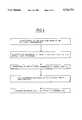
- FIG. 1is a perspective view of a conventional scanner without a separate roll-film unit
- FIG. 2is a perspective view of a conventional scanning unit with a separate roll-film unit mounted thereon;
- FIG. 3is a schematic of the apparatus according to the invention equipped with a conventional scanner and a roll-film unit mounted thereon;
- FIG. 4is a flowchart of a method of operating the apparatus according to the invention.
- FIG. 1is a perspective view of a conventionally configured scanner A; whereas, FIG. 2 shows the combination of the conventional scanner A and the roll-film unit B mounted thereon according to a feature of the invention.
- the conventional scanner Ais here configured as a known flatbed scanner as it is shown in U.S. Pat. No. 5,280,370 incorporated herein by reference.
- This flatbed scannerpermits digitizing the particular individual image objects with high geometric and radiometric precision.
- the image carrier 1is shown in the housing of the scanner A and comprises a pair of glass plates (1a, 1b) in a corresponding frame.
- the transparent individual image object 2 to be processedis mounted between the two glass plates (1a, 1b).
- the upper glass plate 1bcan be flipped out of the way to permit placement of the object.
- the upper glass plate 1bcan also be lifted vertically by a motor.
- the individual image object 2is mounted between the two glass plates (1a, 1b) of the image carrier 1 and is digitized, preferably with high resolution, with the aid of a first electro-optical scanning unit 20 of the conventional scanner A.
- the first electro-optical scanning unit 20 of scanner Aincludes a first detector unit configured as a high-resolving, color separating CCD linear array arrangement.
- the CCD array arrangementcomprises three parallelly arranged CCD linear arrays which operate in a manner known per se.
- the CCD linear array arrangementis attached to a U-shaped carrier 3 having legs (3.1, 3.2).
- the individual image object 2is disposed in the image carrier 1 between these legs.
- the CCD linear array arrangement (not shown in FIG. 1) of the first electro-optical scanning unit 20is mounted on the lower one of the two legs (3.1, 3.2) of the carrier 3; whereas, an illuminating unit is provided on the upper one of the two legs (3.1, 3.2) of the carrier 3.
- the illuminating unitis likewise not shown in FIG. 1.
- transparent objectsare processed in transilluminating light; however, incident light processing of the object can also be realized within the apparatus according to the invention.
- the U-shaped carrier 3 of the first electro-optical scanning unit 20is, in the embodiment shown, movable in the directions shown by the arrows (see FIG. 3) relative to the individual image object 2 mounted stationary in the image carrier 1.
- the U-shaped carrier 3is movable in a defined scanning plane and functions to scan the individual image object 2 in a manner known per se.
- the conventional scanner Aincludes one or more suitable drives which can, for example, be configured as step motors which effect the defined movement of the U-shaped carrier 3 in the scanning plane relative to the object.
- the object in the apparatus of the inventionis fixed during the scanning operation and the scanning unit 20 is moved.
- a preferably high-resolving digitization of the particular image objectis possible with the aid of the CCD linear array arrangement of the first electro-optical scanning unit 20.
- a CCD linear array arrangement suitable for this purposeis the CCD linear array arrangement having the product identification number THX 7821 B of the Thomson Company.
- FIG. 1Also not shown in FIG. 1 is a cover unit which usually covers the forward part of the conventional scanner A during scanning operation.
- FIG. 2shows a perspective view of the combination according to the invention which includes the conventional scanner A described above and the roll-film unit B mounted thereon.
- the roll-film unit Bis accommodated in a housing 4 having the shape of a parallelepiped.
- the housing 4is mounted transversely to the longitudinal direction of the conventional scanner A on the forward portion thereof.
- the roll-film unit Bincludes a motor-driven payout spool 5 and a take-up spool 6 on which the roll film 7, which is to be processed, is wound.
- the roll film 7is guided through the image carrier 1 of the conventional scanner A via transport means (not shown) in the form of corresponding motorized drives of the two spools (5, 6) and suitable roll-film guides.
- a conventional scanning and digitization of the roll-film object 7is possible with the aid of the first electro-optical scanning unit 20.
- the U-shaped carrier 3 of the first electro-optical scanning unit 20is guided as described above over the desired roll-film region in the carrier 1 and the roll-film object is preferably digitized with high resolution in a manner known per se.
- a second electro-optical scanning unit 8is shown which is provided for the roll-film unit B.
- the second electro-optical scanner unit 8is stationary relative to the roll film 7 which is guided past the scanning unit 8.
- the second scanning unit 8includes a second detector unit which is configured as a one-dimensional detector linear array 8.1.
- the detector unitis mounted below the roll film 7 which runs past this unit.
- a second illuminating unit 8.2is disposed on the opposite-lying side of the roll film 7.
- the second electro-optical scanning unit 8functions, inter alia, to generate an overview image of the roll film 7 (which is moved past the scanning unit 8) in real time on a suitable display or monitor (not shown in FIG. 2). In this way, it is possible for the user to view the roll-film images already in advance of the relatively time-consuming, high-resolving digitization of the roll-film object 7 and to select the desired roll-film images which are to be digitized. Further details of this function of the apparatus according to the invention are provided in the descriptive material directed to FIGS. 3 and 4.
- the apparatus according to the inventionhas an approximately T-shaped configuration with a relatively small mounting surface which is only insignificantly greater than the mounting surface of the conventional scanner A.
- FIG. 3A schematic of the entire configuration of the combination according to the invention comprising the conventional scanner A with a roll-film unit B mounted thereon is shown in the block circuit diagram of FIG. 3.
- FIG. 3then corresponds, in principle, to a front elevation view of the apparatus shown in FIGS. 1 and 2.
- the same reference numeralsare used in FIG. 3 as are used in FIGS. 1 and 2.
- the scanner in FIG. 3is configured as a conventional flatbed scanner and the image carrier thereof comprises the two glass plates (1a, 1b).
- the roll film 7 to be processedis guided between the two glass plates (1a, 1b).
- the conventional scannerincludes a first electro-optical scanning unit 20 which includes a U-shaped carrier 3 having legs (3.1, 3.2).
- the roll film 7 to be digitized or even an individual image objectis mounted on the stationary image carrier between the legs (3.1, 3.2).
- a relative movement between the object and the scanning unit 20is required for the scanning operation. In the embodiment shown, this relative movement is realized via the first electro-optical scanning unit 20 which is movable in the scanning plane. In FIG. 3, the scanning plane is horizontal and perpendicular to the plane of the drawing.
- the U-shaped carrier 3 of the first electro-optical scanning unit 20can be definitively positioned in the scanning plane via two motorized drives (9a, 9b).
- the image carrier 1has a stationary position.
- the drive signals of the two motorized drives (9a, 9b) of the first electro-optical scanning unit 20are provided by a motor control module 10a within the control computer 10.
- a first illuminating unit 11is provided on the upper leg 3.2 of the U-shaped carrier 3 of the first electro-optical scanning unit 20 on the side thereof facing toward the object.
- the detector unit mentioned aboveis mounted on the lower leg 3.1.
- the detector unitis in the form of CCD linear array arrangement 12.
- An imaging optic 13is arranged between the image carrier or the roll film 7 and the detector unit 12 for imaging the particular object onto the detector unit 12.
- the imaging optic 13is also mounted on the U-shaped carrier 3 of the first electro-optical scanning unit 20.
- the detector unit 12 of the first electro-optical scanning unit 20is configured as a CCD linear array arrangement 12 in the embodiment shown.
- the electro-optical scanning unit 20is utilized for processing individual image objects as well as for processing roll film.
- the first electro-optical scanning unit 20functions preferably to provide high-resolving and color separating digitization of the particular object and the minimal pixel quantity which can be realized herewith is approximately 7 ⁇ m and the geometric resolution when utilizing a suitable imaging optic 13 is approximately 1/4 ⁇ m.
- the read-out operation from the CCD linear array arrangement 12 or the acceptance of the generated CCD datais controlled via a corresponding CCD processing module 10b within the control computer 10. Thereafter, the signals obtained either reach a host computer 22 for further processing and/or a suitable memory 14. These signals reach the host computer 22 or the memory 14 via a rapid interface 10c in the control computer 10.
- the memory 14can be configured as a conventional computer hard disc, tape memory, magneto-optical disc or other known mass memory.
- a suitable user interface position in the form of a keypad 15 as well as a display 16are connected to the host computer 22.
- the digitized imagesare presented or displayed on the display 16 and the photogrammetrical further processing and evaluation of the image data obtained is then possible.
- the second electro-optical scanning unit 8is assigned to the roll-film unit.
- the second electro-optical scanning unit 8includes a detector unit 8.1 configured as a CCD linear array mounted below the roll film 7 and a second illuminating unit 8.2 mounted on the other side of the roll film 7.
- the CCD linear array 8.1covers preferably the entire width of the roll film 7 which is transported past the array.
- the digitization of the roll-film object 7takes place via the second electro-optical scanning unit 8 in transmitted light in the embodiment shown. In principle, an incident light configuration within the apparatus according to the invention is also realizable.
- the illuminating unit 8.2can include fiber optic means with a condenser optic mounted forward thereof.
- the elements of the second electro-optical scanning unit 8, that is, the detector unit 8.1 as well as the second illuminating unit 8.2are mounted so as to be stationary relative to the roll film 7 which is transported past these elements.
- the relative movement, which is necessary for scanning, between the object and the second electro-optical scanning unit 8is provided by the roll film 7 with its movement past the second electro-optical scanning unit 8.
- the second electro-optical scanning unit 8is assigned to the roll-film unit B and the roll film 7 is transported past this scanning unit.
- the scanning unit 8generates monochrome image data having relatively low resolution.
- the control of the read-out operationtakes place likewise via the CCD processing module 10b within the control computer 10.
- the further signal processingis, in principle, identical to the above-described high-resolution object digitization by means of the first electro-optical scanning unit 20.
- the image data generated via the second electro-optical scanning unit 8are displayed in real time on the display 16 of the host computer 13.
- the display of the detected image datacan also take place on an image screen which is connected to the control computer 10.
- the CCD linear array having the product designation CIPS 305 MA 400 of the Toshiba Companyis suitable for use as a detector unit within the second electro-optical scanning unit 8.
- This CCD linear arraysupplies a geometric resolution of 400 dpi which is adequate for the overview image.
- alternative detector unitssuch as CCD arrays and the like can be used which make possible the required scan rates.
- FIG. 4An advantageous method for operating the apparatus according to the invention is shown in the flowchart of FIG. 4.
- This methodprovides for selecting or determining the desired images and/or image sections on the roll-film object with the aid of an overview image generated in real time in the interactive roll film operating mode described above.
- the selected dataare stored in the control computer and thereafter, in the automatic batch operation, the images or image sections are digitized on the basis of the selected data highly resolved via the first electro-optical scanning unit 20.
- the method described for generating an overview image of reduced resolution in real time and the subsequent high-resolution digitization of selected roll-film sectionsis also possible with only a single electro-optical scanning unit.
- the electro-optical detector unit to be utilizedmust only be able to be operated in a suitable low-resolution mode and a high-resolution mode. In the low-resolution mode, an adequately high scan speed must be provided.
- the scanning operation with the second electro-optical scanning unit 8is possible only with a limited speed of approximately 20 cm/sec because of the limited scanning rate of the detector unit or CCD linear array used. For this reason, it is advantageous for the prepositioning of the roll film 7, to arrange at least one but preferably several detectors (17, 18) within the roll-film unit.
- a first detector 17is assigned to the payout spool 5 of the roll-film unit.
- the first detector 17detects the rotational angle during the rotational movement of the payout spool 5.
- the first detector 17is preferably configured as a rotation pulse transducer which is available in the marketplace under the product identification HEDS 5540 of the Hewlett Packard Company.
- a further second detector 18is provided directly on the transported roll film 7 and detects the distance traveled by the transported film.
- the second detector 18is configured as a pick off wheel likewise having a pulse generator assigned thereto.
- the signals supplied by the two detectors (17, 18)reach a roll-film position module 10d which is provided in the control computer 10.
- the absolute length L of the film still available on the payout spool 5is determined on the basis of the supplied signals of the detectors (17, 18) as well as a series of known system parameters via the roll-film position module 10d in the control computer 10. Furthermore, in this way, the position of an image with a known image number is continuously known.
- kair factor (a measure as to how much air is enclosed in the film roll, for example 10%);
- n snumber of the measured pulses of the film spool pulse generator
- n gnumber of the measured pulses of the pickoff wheel pulse generator
- r sradius of the shaft of the payout spool
- Llength of the film still available on the payout spool.
- the prepositioning of the roll film 7takes place via a rapid rewinding at a film transport speed of approximately 1.5 m/sec on the basis of the data supplied by the roll-film position module 10d.
- the corresponding control signalsare transmitted from the control computer 10 to the drives of the roll-film or to the transport means of the roll-film unit.
- the userviews the overview image via the display 16 and selects, as described above, the images or image sections of interest.
- the overview imageis generated during rewinding in real time.
- the method described for prepositioning the roll film 7is also possible in the above-mentioned automated batch operation.
- the roll film 7can be rapidly prepositioned based on the position data determined from the roll film position module 10d and thereafter, the automated high-resolution digitization of the desired image section can take place.
- the position data, which are determined by the roll-film position module 10dare still relevant with respect to the film material still available on the payout spool 5 in order to timely stop roll-film processing before the roll film 7 runs off the payout spool 5.
- a corresponding display of a warning signal for the useris provided.
- the apparatus of the inventionthereby affords the possibility of conveniently digitizing roll-film material in addition to processing individual image objects.
- the processing of the roll filmis optional without a greater retrofit resulting or even affecting the conventional scan unit for processing the individual image objects.
Landscapes
- Engineering & Computer Science (AREA)
- Multimedia (AREA)
- Signal Processing (AREA)
- Physics & Mathematics (AREA)
- General Physics & Mathematics (AREA)
- Radar, Positioning & Navigation (AREA)
- Remote Sensing (AREA)
- Facsimile Scanning Arrangements (AREA)
- Facsimiles In General (AREA)
Abstract
Description
Claims (20)
Applications Claiming Priority (2)
| Application Number | Priority Date | Filing Date | Title |
|---|---|---|---|
| DE4442445 | 1994-11-29 | ||
| DE4442445.0 | 1994-11-29 |
Publications (1)
| Publication Number | Publication Date |
|---|---|
| US5726773Atrue US5726773A (en) | 1998-03-10 |
Family
ID=6534436
Family Applications (1)
| Application Number | Title | Priority Date | Filing Date |
|---|---|---|---|
| US08/563,550Expired - Fee RelatedUS5726773A (en) | 1994-11-29 | 1995-11-28 | Apparatus for scanning and digitizing photographic image objects and method of operating said apparatus |
Country Status (3)
| Country | Link |
|---|---|
| US (1) | US5726773A (en) |
| CH (1) | CH690639A5 (en) |
| DE (2) | DE19542486A1 (en) |
Cited By (66)
| Publication number | Priority date | Publication date | Assignee | Title |
|---|---|---|---|---|
| WO1998034157A3 (en)* | 1997-01-30 | 1998-12-10 | Applied Science Fiction Inc | System and method for latent film recovery in electronic film development |
| WO2001058139A1 (en)* | 2000-02-03 | 2001-08-09 | Agfa-Gevaert Aktiengesellschaft | Method and device for digitally detecting a photographic film |
| US20010030685A1 (en)* | 1999-12-30 | 2001-10-18 | Darbin Stephen P. | Method and apparatus for digital film processing using a scanning station having a single sensor |
| US20010031084A1 (en)* | 1999-12-17 | 2001-10-18 | Cannata Philip E. | Method and system for selective enhancement of image data |
| US6313870B1 (en)* | 1996-02-21 | 2001-11-06 | Olympus Optical Co. Ltd. | Modular photographic film digitizing apparatus |
| US20010040701A1 (en)* | 2000-02-03 | 2001-11-15 | Edgar Albert D. | Photographic film having time resolved sensitivity distinction |
| US20020051215A1 (en)* | 1999-12-30 | 2002-05-02 | Thering Michael R. | Methods and apparatus for transporting and positioning film in a digital film processing system |
| US6393160B1 (en) | 1998-03-13 | 2002-05-21 | Applied Science Fiction | Image defect correction in transform space |
| US6404516B1 (en) | 1999-02-22 | 2002-06-11 | Applied Science Fiction, Inc. | Parametric image stitching |
| US20020080409A1 (en)* | 1999-12-31 | 2002-06-27 | Keyes Michael P. | Digital film processing method |
| US6437358B1 (en) | 1999-02-04 | 2002-08-20 | Applied Science Fiction, Inc. | Apparatus and methods for capturing defect data |
| US6442301B1 (en) | 1997-01-06 | 2002-08-27 | Applied Science Fiction, Inc. | Apparatus and method for defect channel nulling |
| US6439784B1 (en) | 1999-08-17 | 2002-08-27 | Applied Science Fiction, Inc. | Method and system for using calibration patches in electronic film processing |
| US20020118402A1 (en)* | 2000-09-19 | 2002-08-29 | Shaw Timothy C. | Film bridge for digital film scanning system |
| US6443639B1 (en) | 1999-06-29 | 2002-09-03 | Applied Science Fiction, Inc. | Slot coater device for applying developer to film for electronic film development |
| US6447178B2 (en) | 1999-12-30 | 2002-09-10 | Applied Science Fiction, Inc. | System, method, and apparatus for providing multiple extrusion widths |
| US20020126327A1 (en)* | 2000-09-21 | 2002-09-12 | Edgar Albert D. | Method and system for improving scanned image detail |
| US6461061B2 (en) | 1999-12-30 | 2002-10-08 | Applied Science Fiction, Inc. | System and method for digital film development using visible light |
| US20020146171A1 (en)* | 2000-10-01 | 2002-10-10 | Applied Science Fiction, Inc. | Method, apparatus and system for black segment detection |
| US6475711B1 (en) | 1999-12-31 | 2002-11-05 | Applied Science Fiction, Inc. | Photographic element and digital film processing method using same |
| US6487321B1 (en) | 1999-09-16 | 2002-11-26 | Applied Science Fiction | Method and system for altering defects in a digital image |
| US20020176123A1 (en)* | 2001-04-17 | 2002-11-28 | Yasuhiro Hamano | Mount carrier unit and film scanner |
| US6498867B1 (en) | 1999-10-08 | 2002-12-24 | Applied Science Fiction Inc. | Method and apparatus for differential illumination image-capturing and defect handling |
| US20030002092A1 (en)* | 2001-06-28 | 2003-01-02 | Tecu Kirk Steven | System, method and adapter for scanning a roll of transparent media |
| US6503002B1 (en) | 1996-12-05 | 2003-01-07 | Applied Science Fiction, Inc. | Method and apparatus for reducing noise in electronic film development |
| US6505977B2 (en) | 1999-12-30 | 2003-01-14 | Applied Science Fiction, Inc. | System and method for digital color dye film processing |
| US6512601B1 (en) | 1998-02-23 | 2003-01-28 | Applied Science Fiction, Inc. | Progressive area scan in electronic film development |
| US20030048480A1 (en)* | 2001-09-10 | 2003-03-13 | Hsiu-O Hsu | Photographic film scanning device |
| US6540416B2 (en) | 1999-12-30 | 2003-04-01 | Applied Science Fiction, Inc. | System and method for digital film development using visible light |
| US6554504B2 (en) | 1999-12-30 | 2003-04-29 | Applied Science Fiction, Inc. | Distributed digital film processing system and method |
| US6590679B1 (en) | 1998-02-04 | 2003-07-08 | Applied Science Fiction, Inc. | Multilinear array sensor with an infrared line |
| US6594041B1 (en) | 1998-11-20 | 2003-07-15 | Applied Science Fiction, Inc. | Log time processing and stitching system |
| US6593558B1 (en) | 1996-05-10 | 2003-07-15 | Applied Science Fiction, Inc. | Luminance-priority electronic color image sensor |
| US20030133710A1 (en)* | 2001-07-16 | 2003-07-17 | Winberg Paul N. | System and method for digital film development using visible light |
| US6599036B2 (en) | 2000-02-03 | 2003-07-29 | Applied Science Fiction, Inc. | Film processing solution cartridge and method for developing and digitizing film |
| US20030147102A1 (en)* | 2002-01-25 | 2003-08-07 | Umax Data Systems Inc. | Two-directions scanning method |
| US6614946B1 (en) | 1999-10-08 | 2003-09-02 | Eastman Kodak Company | System and method for correcting defects in digital images through selective fill-in from surrounding areas |
| US6619863B2 (en) | 2000-02-03 | 2003-09-16 | Eastman Kodak Company | Method and system for capturing film images |
| US20030179422A1 (en)* | 2002-03-25 | 2003-09-25 | Linda Liu | System and method for switching screens from overview and preview |
| US6628432B1 (en)* | 1998-11-17 | 2003-09-30 | Seiko Epson Corporation | Image reader and image reading method |
| US6683995B2 (en) | 1999-12-23 | 2004-01-27 | Eastman Kodak Company | Method and apparatus for correcting large defects in digital images |
| US20040028288A1 (en)* | 2002-01-14 | 2004-02-12 | Edgar Albert D. | Method, system, and software for improving signal quality using pyramidal decomposition |
| US6704458B2 (en) | 1999-12-29 | 2004-03-09 | Eastman Kodak Company | Method and apparatus for correcting heavily damaged images |
| US20040047585A1 (en)* | 2000-12-05 | 2004-03-11 | Duong Dung T. | Light transfer device and system |
| US6707557B2 (en) | 1999-12-30 | 2004-03-16 | Eastman Kodak Company | Method and system for estimating sensor dark current drift and sensor/illumination non-uniformities |
| US6711302B1 (en) | 1999-10-20 | 2004-03-23 | Eastman Kodak Company | Method and system for altering defects in digital image |
| US6720560B1 (en) | 1999-12-30 | 2004-04-13 | Eastman Kodak Company | Method and apparatus for scanning images |
| US6733960B2 (en) | 2001-02-09 | 2004-05-11 | Eastman Kodak Company | Digital film processing solutions and method of digital film processing |
| US6781620B1 (en) | 1999-03-16 | 2004-08-24 | Eastman Kodak Company | Mixed-element stitching and noise reduction system |
| US6786655B2 (en) | 2000-02-03 | 2004-09-07 | Eastman Kodak Company | Method and system for self-service film processing |
| US6788335B2 (en) | 1999-12-30 | 2004-09-07 | Eastman Kodak Company | Pulsed illumination signal modulation control & adjustment method and system |
| US6813392B2 (en) | 1999-12-30 | 2004-11-02 | Eastman Kodak Company | Method and apparatus for aligning multiple scans of the same area of a medium using mathematical correlation |
| US6862117B1 (en) | 1999-12-30 | 2005-03-01 | Eastman Kodak Company | Method and apparatus for reducing the effect of bleed-through on captured images |
| US6864973B2 (en) | 1999-12-30 | 2005-03-08 | Eastman Kodak Company | Method and apparatus to pre-scan and pre-treat film for improved digital film processing handling |
| US6924911B1 (en) | 1999-10-12 | 2005-08-02 | Eastman Kodak Company | Method and system for multi-sensor signal detection |
| US6943920B2 (en) | 2000-02-03 | 2005-09-13 | Eastman Kodak Company | Method, system, and software for signal processing using pyramidal decomposition |
| US6965692B1 (en) | 1999-12-30 | 2005-11-15 | Eastman Kodak Company | Method and apparatus for improving the quality of reconstructed information |
| US6987892B2 (en) | 2001-04-19 | 2006-01-17 | Eastman Kodak Company | Method, system and software for correcting image defects |
| US6990251B2 (en) | 2000-02-03 | 2006-01-24 | Eastman Kodak Company | Method, system, and software for signal processing using sheep and shepherd artifacts |
| US7020344B2 (en) | 2000-02-03 | 2006-03-28 | Eastman Kodak Company | Match blur system and method |
| US20060182337A1 (en)* | 2000-06-28 | 2006-08-17 | Ford Benjamin C | Method and apparatus for improving the quality of reconstructed information |
| US20060192857A1 (en)* | 2004-02-13 | 2006-08-31 | Sony Corporation | Image processing device, image processing method, and program |
| US7164511B2 (en) | 1999-12-29 | 2007-01-16 | Eastman Kodak Company | Distinguishing positive and negative films system and method |
| US20080284847A1 (en)* | 2007-05-15 | 2008-11-20 | E-Image Data Corporation | Digital Microform Imaging Apparatus |
| US20090256087A1 (en)* | 2008-04-14 | 2009-10-15 | Heidelberger Druckmaschinen Ag | Measuring Apparatus Having a Movable Measuring Device in a Press |
| US9158983B2 (en) | 2010-07-08 | 2015-10-13 | E-Image Data Corporation | Microform word search method and apparatus |
Families Citing this family (2)
| Publication number | Priority date | Publication date | Assignee | Title |
|---|---|---|---|---|
| JPH10173845A (en)* | 1996-12-13 | 1998-06-26 | Fuji Photo Film Co Ltd | Image forming device |
| CN113264399A (en)* | 2021-04-26 | 2021-08-17 | 杭州创恒电子技术开发有限公司 | Footprint image acquisition equipment capable of automatically changing film and footprint image acquisition method |
Citations (8)
| Publication number | Priority date | Publication date | Assignee | Title |
|---|---|---|---|---|
| US4324484A (en)* | 1980-10-01 | 1982-04-13 | Bell & Howell Company | Microfilm filing system |
| US5280370A (en)* | 1989-09-11 | 1994-01-18 | Intergraph Corporation | Apparatus and method for scanning by means of a rotatable detector array |
| US5283668A (en)* | 1990-08-28 | 1994-02-01 | Canon Kabushiki Kaisha | Image reading apparatus with image sensor having selectively readable segments |
| US5351139A (en)* | 1991-11-28 | 1994-09-27 | Canon Kabushiki Kaisha | Apparatus for photographing photographed film |
| US5381245A (en)* | 1990-01-18 | 1995-01-10 | X-Ray Scanner Corporation | X-ray film scanning and digitizing apparatus |
| US5430550A (en)* | 1991-06-14 | 1995-07-04 | Minolta Camera Kabushiki Kaisha | Image reading apparatus which corrects for positional and angular deviation between the image sensor and the document |
| US5432622A (en)* | 1992-05-29 | 1995-07-11 | Johnston; Gregory E. | High-resolution scanning apparatus |
| US5477343A (en)* | 1992-06-18 | 1995-12-19 | Anacomp, Inc. | Micrographic reader with digitized image |
Family Cites Families (2)
| Publication number | Priority date | Publication date | Assignee | Title |
|---|---|---|---|---|
| US3581964A (en)* | 1969-03-26 | 1971-06-01 | Ncr Co | Film transport mechanism |
| JPH01268254A (en)* | 1988-04-19 | 1989-10-25 | Minolta Camera Co Ltd | Film projection device |
- 1995
- 1995-11-06CHCH03122/95Apatent/CH690639A5/ennot_activeIP Right Cessation
- 1995-11-15DEDE19542486Apatent/DE19542486A1/ennot_activeWithdrawn
- 1995-11-28USUS08/563,550patent/US5726773A/ennot_activeExpired - Fee Related
- 1995-11-28DEDE19544178Apatent/DE19544178B4/ennot_activeExpired - Lifetime
Patent Citations (8)
| Publication number | Priority date | Publication date | Assignee | Title |
|---|---|---|---|---|
| US4324484A (en)* | 1980-10-01 | 1982-04-13 | Bell & Howell Company | Microfilm filing system |
| US5280370A (en)* | 1989-09-11 | 1994-01-18 | Intergraph Corporation | Apparatus and method for scanning by means of a rotatable detector array |
| US5381245A (en)* | 1990-01-18 | 1995-01-10 | X-Ray Scanner Corporation | X-ray film scanning and digitizing apparatus |
| US5283668A (en)* | 1990-08-28 | 1994-02-01 | Canon Kabushiki Kaisha | Image reading apparatus with image sensor having selectively readable segments |
| US5430550A (en)* | 1991-06-14 | 1995-07-04 | Minolta Camera Kabushiki Kaisha | Image reading apparatus which corrects for positional and angular deviation between the image sensor and the document |
| US5351139A (en)* | 1991-11-28 | 1994-09-27 | Canon Kabushiki Kaisha | Apparatus for photographing photographed film |
| US5432622A (en)* | 1992-05-29 | 1995-07-11 | Johnston; Gregory E. | High-resolution scanning apparatus |
| US5477343A (en)* | 1992-06-18 | 1995-12-19 | Anacomp, Inc. | Micrographic reader with digitized image |
Cited By (101)
| Publication number | Priority date | Publication date | Assignee | Title |
|---|---|---|---|---|
| US6313870B1 (en)* | 1996-02-21 | 2001-11-06 | Olympus Optical Co. Ltd. | Modular photographic film digitizing apparatus |
| US6593558B1 (en) | 1996-05-10 | 2003-07-15 | Applied Science Fiction, Inc. | Luminance-priority electronic color image sensor |
| US6503002B1 (en) | 1996-12-05 | 2003-01-07 | Applied Science Fiction, Inc. | Method and apparatus for reducing noise in electronic film development |
| US6442301B1 (en) | 1997-01-06 | 2002-08-27 | Applied Science Fiction, Inc. | Apparatus and method for defect channel nulling |
| WO1998034157A3 (en)* | 1997-01-30 | 1998-12-10 | Applied Science Fiction Inc | System and method for latent film recovery in electronic film development |
| US6558052B2 (en)* | 1997-01-30 | 2003-05-06 | Applied Science Fiction, Inc. | System and method for latent film recovery in electronic film development |
| US6193425B1 (en) | 1997-01-30 | 2001-02-27 | Applied Science Fiction, Inc. | System and method for latent film recovery in electronic film development |
| US6017688A (en)* | 1997-01-30 | 2000-01-25 | Applied Science Fiction, Inc. | System and method for latent film recovery in electronic film development |
| US6590679B1 (en) | 1998-02-04 | 2003-07-08 | Applied Science Fiction, Inc. | Multilinear array sensor with an infrared line |
| US6512601B1 (en) | 1998-02-23 | 2003-01-28 | Applied Science Fiction, Inc. | Progressive area scan in electronic film development |
| US6393160B1 (en) | 1998-03-13 | 2002-05-21 | Applied Science Fiction | Image defect correction in transform space |
| US6628432B1 (en)* | 1998-11-17 | 2003-09-30 | Seiko Epson Corporation | Image reader and image reading method |
| US6594041B1 (en) | 1998-11-20 | 2003-07-15 | Applied Science Fiction, Inc. | Log time processing and stitching system |
| US6437358B1 (en) | 1999-02-04 | 2002-08-20 | Applied Science Fiction, Inc. | Apparatus and methods for capturing defect data |
| US6404516B1 (en) | 1999-02-22 | 2002-06-11 | Applied Science Fiction, Inc. | Parametric image stitching |
| US6781620B1 (en) | 1999-03-16 | 2004-08-24 | Eastman Kodak Company | Mixed-element stitching and noise reduction system |
| US6443639B1 (en) | 1999-06-29 | 2002-09-03 | Applied Science Fiction, Inc. | Slot coater device for applying developer to film for electronic film development |
| US6439784B1 (en) | 1999-08-17 | 2002-08-27 | Applied Science Fiction, Inc. | Method and system for using calibration patches in electronic film processing |
| US6487321B1 (en) | 1999-09-16 | 2002-11-26 | Applied Science Fiction | Method and system for altering defects in a digital image |
| US6650789B2 (en) | 1999-09-16 | 2003-11-18 | Eastman Kodak Company | Method and system for altering defects in a digital image |
| US6614946B1 (en) | 1999-10-08 | 2003-09-02 | Eastman Kodak Company | System and method for correcting defects in digital images through selective fill-in from surrounding areas |
| US6498867B1 (en) | 1999-10-08 | 2002-12-24 | Applied Science Fiction Inc. | Method and apparatus for differential illumination image-capturing and defect handling |
| US6924911B1 (en) | 1999-10-12 | 2005-08-02 | Eastman Kodak Company | Method and system for multi-sensor signal detection |
| US6711302B1 (en) | 1999-10-20 | 2004-03-23 | Eastman Kodak Company | Method and system for altering defects in digital image |
| US6915021B2 (en) | 1999-12-17 | 2005-07-05 | Eastman Kodak Company | Method and system for selective enhancement of image data |
| US20010031084A1 (en)* | 1999-12-17 | 2001-10-18 | Cannata Philip E. | Method and system for selective enhancement of image data |
| US6683995B2 (en) | 1999-12-23 | 2004-01-27 | Eastman Kodak Company | Method and apparatus for correcting large defects in digital images |
| US7164511B2 (en) | 1999-12-29 | 2007-01-16 | Eastman Kodak Company | Distinguishing positive and negative films system and method |
| US6704458B2 (en) | 1999-12-29 | 2004-03-09 | Eastman Kodak Company | Method and apparatus for correcting heavily damaged images |
| US6554504B2 (en) | 1999-12-30 | 2003-04-29 | Applied Science Fiction, Inc. | Distributed digital film processing system and method |
| US6447178B2 (en) | 1999-12-30 | 2002-09-10 | Applied Science Fiction, Inc. | System, method, and apparatus for providing multiple extrusion widths |
| US6813392B2 (en) | 1999-12-30 | 2004-11-02 | Eastman Kodak Company | Method and apparatus for aligning multiple scans of the same area of a medium using mathematical correlation |
| US6540416B2 (en) | 1999-12-30 | 2003-04-01 | Applied Science Fiction, Inc. | System and method for digital film development using visible light |
| US6705777B2 (en) | 1999-12-30 | 2004-03-16 | Eastman Kodak Company | System and method for digital film development using visible light |
| US6505977B2 (en) | 1999-12-30 | 2003-01-14 | Applied Science Fiction, Inc. | System and method for digital color dye film processing |
| US6707557B2 (en) | 1999-12-30 | 2004-03-16 | Eastman Kodak Company | Method and system for estimating sensor dark current drift and sensor/illumination non-uniformities |
| US6793417B2 (en) | 1999-12-30 | 2004-09-21 | Eastman Kodak Company | System and method for digital film development using visible light |
| US20050128474A1 (en)* | 1999-12-30 | 2005-06-16 | Young Robert S.Jr. | Method and apparatus to pre-scan and pre-treat film for improved digital film processing handling |
| US6788335B2 (en) | 1999-12-30 | 2004-09-07 | Eastman Kodak Company | Pulsed illumination signal modulation control & adjustment method and system |
| US6965692B1 (en) | 1999-12-30 | 2005-11-15 | Eastman Kodak Company | Method and apparatus for improving the quality of reconstructed information |
| US20030142975A1 (en)* | 1999-12-30 | 2003-07-31 | Edgar Albert D. | System and method for digital film development using visible light |
| US6461061B2 (en) | 1999-12-30 | 2002-10-08 | Applied Science Fiction, Inc. | System and method for digital film development using visible light |
| US20010030685A1 (en)* | 1999-12-30 | 2001-10-18 | Darbin Stephen P. | Method and apparatus for digital film processing using a scanning station having a single sensor |
| US6862117B1 (en) | 1999-12-30 | 2005-03-01 | Eastman Kodak Company | Method and apparatus for reducing the effect of bleed-through on captured images |
| US6864973B2 (en) | 1999-12-30 | 2005-03-08 | Eastman Kodak Company | Method and apparatus to pre-scan and pre-treat film for improved digital film processing handling |
| US6720560B1 (en) | 1999-12-30 | 2004-04-13 | Eastman Kodak Company | Method and apparatus for scanning images |
| US20020051215A1 (en)* | 1999-12-30 | 2002-05-02 | Thering Michael R. | Methods and apparatus for transporting and positioning film in a digital film processing system |
| US6664034B2 (en) | 1999-12-31 | 2003-12-16 | Eastman Kodak Company | Digital film processing method |
| US20020080409A1 (en)* | 1999-12-31 | 2002-06-27 | Keyes Michael P. | Digital film processing method |
| US6910816B2 (en) | 1999-12-31 | 2005-06-28 | Eastman Kodak Company | Digital film processing method |
| US20040053175A1 (en)* | 1999-12-31 | 2004-03-18 | Keyes Michael P. | Digital film processing method |
| US6475711B1 (en) | 1999-12-31 | 2002-11-05 | Applied Science Fiction, Inc. | Photographic element and digital film processing method using same |
| US20050008981A1 (en)* | 1999-12-31 | 2005-01-13 | Keyes Michael P. | Digital film processing method |
| US6824966B2 (en) | 1999-12-31 | 2004-11-30 | Eastman Kodak Company | Digital film processing method |
| US6599036B2 (en) | 2000-02-03 | 2003-07-29 | Applied Science Fiction, Inc. | Film processing solution cartridge and method for developing and digitizing film |
| US20010040701A1 (en)* | 2000-02-03 | 2001-11-15 | Edgar Albert D. | Photographic film having time resolved sensitivity distinction |
| US20040076425A1 (en)* | 2000-02-03 | 2004-04-22 | Patterson Richard A. | Film processing solution cartridge and method for developing and digitizing film |
| US6913404B2 (en) | 2000-02-03 | 2005-07-05 | Eastman Kodak Company | Film processing solution cartridge and method for developing and digitizing film |
| WO2001058139A1 (en)* | 2000-02-03 | 2001-08-09 | Agfa-Gevaert Aktiengesellschaft | Method and device for digitally detecting a photographic film |
| US6619863B2 (en) | 2000-02-03 | 2003-09-16 | Eastman Kodak Company | Method and system for capturing film images |
| US6786655B2 (en) | 2000-02-03 | 2004-09-07 | Eastman Kodak Company | Method and system for self-service film processing |
| US7020344B2 (en) | 2000-02-03 | 2006-03-28 | Eastman Kodak Company | Match blur system and method |
| US6990251B2 (en) | 2000-02-03 | 2006-01-24 | Eastman Kodak Company | Method, system, and software for signal processing using sheep and shepherd artifacts |
| US6943920B2 (en) | 2000-02-03 | 2005-09-13 | Eastman Kodak Company | Method, system, and software for signal processing using pyramidal decomposition |
| US20060182337A1 (en)* | 2000-06-28 | 2006-08-17 | Ford Benjamin C | Method and apparatus for improving the quality of reconstructed information |
| US20020118402A1 (en)* | 2000-09-19 | 2002-08-29 | Shaw Timothy C. | Film bridge for digital film scanning system |
| US20020176113A1 (en)* | 2000-09-21 | 2002-11-28 | Edgar Albert D. | Dynamic image correction and imaging systems |
| US20020126327A1 (en)* | 2000-09-21 | 2002-09-12 | Edgar Albert D. | Method and system for improving scanned image detail |
| US7016080B2 (en) | 2000-09-21 | 2006-03-21 | Eastman Kodak Company | Method and system for improving scanned image detail |
| US20020146171A1 (en)* | 2000-10-01 | 2002-10-10 | Applied Science Fiction, Inc. | Method, apparatus and system for black segment detection |
| US6888997B2 (en) | 2000-12-05 | 2005-05-03 | Eastman Kodak Company | Waveguide device and optical transfer system for directing light to an image plane |
| US20040047585A1 (en)* | 2000-12-05 | 2004-03-11 | Duong Dung T. | Light transfer device and system |
| US6733960B2 (en) | 2001-02-09 | 2004-05-11 | Eastman Kodak Company | Digital film processing solutions and method of digital film processing |
| US7099053B2 (en)* | 2001-04-17 | 2006-08-29 | Noritsu Koki Co., Ltd. | Mount carrier unit and film scanner |
| US20020176123A1 (en)* | 2001-04-17 | 2002-11-28 | Yasuhiro Hamano | Mount carrier unit and film scanner |
| US6987892B2 (en) | 2001-04-19 | 2006-01-17 | Eastman Kodak Company | Method, system and software for correcting image defects |
| GB2377698A (en)* | 2001-06-28 | 2003-01-22 | Hewlett Packard Co | Adapter, method and system for scanning a roll of transparent media |
| US20030002092A1 (en)* | 2001-06-28 | 2003-01-02 | Tecu Kirk Steven | System, method and adapter for scanning a roll of transparent media |
| US6916125B2 (en) | 2001-07-16 | 2005-07-12 | Eastman Kodak Company | Method for film inspection and development |
| US20030133710A1 (en)* | 2001-07-16 | 2003-07-17 | Winberg Paul N. | System and method for digital film development using visible light |
| US6805501B2 (en) | 2001-07-16 | 2004-10-19 | Eastman Kodak Company | System and method for digital film development using visible light |
| US20040170425A1 (en)* | 2001-07-16 | 2004-09-02 | Winberg Paul N. | System and method for digital film development using visible light |
| US7295350B2 (en)* | 2001-09-10 | 2007-11-13 | Transpacific Ip Ltd | Photographic film scanning device |
| US20030048480A1 (en)* | 2001-09-10 | 2003-03-13 | Hsiu-O Hsu | Photographic film scanning device |
| US20040028288A1 (en)* | 2002-01-14 | 2004-02-12 | Edgar Albert D. | Method, system, and software for improving signal quality using pyramidal decomposition |
| US7263240B2 (en) | 2002-01-14 | 2007-08-28 | Eastman Kodak Company | Method, system, and software for improving signal quality using pyramidal decomposition |
| US20030147102A1 (en)* | 2002-01-25 | 2003-08-07 | Umax Data Systems Inc. | Two-directions scanning method |
| US7492489B2 (en)* | 2002-01-25 | 2009-02-17 | Kuan-Yu Lee | Two-directions scanning method |
| US7929185B2 (en)* | 2002-03-25 | 2011-04-19 | Transpacific Systems, Llc | System and method for switching screens from overview and preview |
| US20030179422A1 (en)* | 2002-03-25 | 2003-09-25 | Linda Liu | System and method for switching screens from overview and preview |
| US20060192857A1 (en)* | 2004-02-13 | 2006-08-31 | Sony Corporation | Image processing device, image processing method, and program |
| US20080284847A1 (en)* | 2007-05-15 | 2008-11-20 | E-Image Data Corporation | Digital Microform Imaging Apparatus |
| US8269890B2 (en) | 2007-05-15 | 2012-09-18 | E-Image Data Corporation | Digital microform imaging apparatus |
| US8537279B2 (en) | 2007-05-15 | 2013-09-17 | E-Imagedata Corp. | Digital microform imaging apparatus |
| US9179019B2 (en) | 2007-05-15 | 2015-11-03 | E-Imagedata Corp. | Digital microform imaging apparatus |
| US9197766B2 (en) | 2007-05-15 | 2015-11-24 | E-Imagedata Corp. | Digital microform imaging apparatus |
| US20090256087A1 (en)* | 2008-04-14 | 2009-10-15 | Heidelberger Druckmaschinen Ag | Measuring Apparatus Having a Movable Measuring Device in a Press |
| US8120000B2 (en)* | 2008-04-14 | 2012-02-21 | Heidelberger Druckmaschinen Ag | Measuring apparatus having a movable measuring device in a press |
| US9158983B2 (en) | 2010-07-08 | 2015-10-13 | E-Image Data Corporation | Microform word search method and apparatus |
| US9864907B2 (en) | 2010-07-08 | 2018-01-09 | E-Imagedata Corp. | Microform word search method and apparatus |
| US10185874B2 (en) | 2010-07-08 | 2019-01-22 | E-Image Data Corporation | Microform word search method and apparatus |
Also Published As
| Publication number | Publication date |
|---|---|
| DE19544178B4 (en) | 2007-12-27 |
| CH690639A5 (en) | 2000-11-15 |
| DE19544178A1 (en) | 1996-05-30 |
| DE19542486A1 (en) | 1996-06-13 |
Similar Documents
| Publication | Publication Date | Title |
|---|---|---|
| US5726773A (en) | Apparatus for scanning and digitizing photographic image objects and method of operating said apparatus | |
| US5047871A (en) | Direction scaling method and apparatus for image scanning resolution control | |
| EP0355221A1 (en) | Method and apparatus of photogrammetric mensuration with a reseau grid | |
| JPH07236029A (en) | Compact document imager | |
| EP0647479A2 (en) | Parcel sorting system | |
| EP0627069B1 (en) | Method and apparatus for measuring the shape of a surface of an object | |
| JPH09284749A (en) | Method for photographing tunnel wall surface and photographing device using the method | |
| US4682242A (en) | Apparatus for image posture correction | |
| US5086392A (en) | Radiation image diagnostic apparatus | |
| US4803561A (en) | Image reading method and apparatus | |
| US4809066A (en) | Method of image mensuration with selectively visible and invisible reseau grid marks | |
| EP1387565A2 (en) | Imaging apparatus having automatic media identification and method therefor | |
| JP2000134433A (en) | Converter for optical scanner | |
| JP2876507B2 (en) | Wafer foreign matter inspection device | |
| EP1020719A1 (en) | Apparatus and method for determining the optical distortion of a transparent substrate | |
| EP0146472B1 (en) | Image input apparatus | |
| US4928169A (en) | Mensuration frame grabbing apparatus | |
| US4924505A (en) | Method of mensuration of an image on an object | |
| JP2545209B2 (en) | Crystal defect inspection method and inspection apparatus therefor | |
| US4669838A (en) | Roll film document image storage and retrieval apparatus and system | |
| US3693042A (en) | Rapid film reader/recorder utilizing movable cylindrical lens | |
| US4841455A (en) | Reseau apparatus for photogrammetry devices | |
| US3460099A (en) | High-speed film reader/recorder with grid reference | |
| US7477434B2 (en) | Process and apparatus for retrieving information projected image-wise on a photo-stimulable phosphor imaging substrate utilizing a non-orthogonal pentaprism | |
| US3339815A (en) | Film indexing method and apparatus for high speed film reading |
Legal Events
| Date | Code | Title | Description |
|---|---|---|---|
| FEPP | Fee payment procedure | Free format text:PAYOR NUMBER ASSIGNED (ORIGINAL EVENT CODE: ASPN); ENTITY STATUS OF PATENT OWNER: LARGE ENTITY | |
| CC | Certificate of correction | ||
| FPAY | Fee payment | Year of fee payment:4 | |
| FPAY | Fee payment | Year of fee payment:8 | |
| AS | Assignment | Owner name:Z/I IMAGING GMBH, GERMANY Free format text:AGREEMENT AS TO CAPITAL INVESTMENT;ASSIGNOR:CARL-ZEISS-STIFTUNG, DOING BUSINESS UNDER THE FIRM NAME CARL ZEISS;REEL/FRAME:019580/0200 Effective date:19990930 | |
| AS | Assignment | Owner name:Z/I IMAGING GMBH, GERMANY Free format text:ASSIGNMENT OF ASSIGNORS INTEREST;ASSIGNOR:Z/I IMAGING GMBH;REEL/FRAME:019588/0457 Effective date:20040908 | |
| AS | Assignment | Owner name:Z/I IMAGING GMBH, GERMANY Free format text:RE-RECORD TO CORRECT THE DATE OF THE CHANGE OF ADDRESS, PREVIOUSLY RECORDED AT REEL 019588 FRAME 0457.;ASSIGNOR:Z/I IMAGING GMBH;REEL/FRAME:019965/0452 Effective date:20030819 Owner name:INTERGRAPH (DEUTSCHLAND) GMBH, GERMANY Free format text:MERGER;ASSIGNOR:Z/I IMAGING GMBH;REEL/FRAME:019965/0445 Effective date:20040508 | |
| AS | Assignment | Owner name:INTERGRAPH HARDWARE TECHNOLOGIES CO., NEVADA Free format text:ASSIGNMENT OF ASSIGNORS INTEREST;ASSIGNOR:INTERGRAPH (DEUTSCHLAND) GMBH;REEL/FRAME:020018/0001 Effective date:20051216 | |
| REMI | Maintenance fee reminder mailed | ||
| LAPS | Lapse for failure to pay maintenance fees | ||
| STCH | Information on status: patent discontinuation | Free format text:PATENT EXPIRED DUE TO NONPAYMENT OF MAINTENANCE FEES UNDER 37 CFR 1.362 | |
| FP | Lapsed due to failure to pay maintenance fee | Effective date:20100310 | |
| AS | Assignment | Owner name:INTERGRAPH DC CORPORATION - SUBSIDIARY 3, ALABAMA Free format text:TERMINATION AND RELEASE OF SECOND LIEN INTELLECTUAL PROPERTY SECURITY INTEREST;ASSIGNOR:WACHOVIA BANK, NATIONAL ASSOCIATION;REEL/FRAME:025892/0028 Effective date:20101028 Owner name:WORLDWIDE SERVICES, INC., ALABAMA Free format text:TERMINATION AND RELEASE OF FIRST LIEN INTELLECTUAL PROPERTY SECURITY INTEREST;ASSIGNOR:MORGAN STANLEY & CO. INCORPORATED;REEL/FRAME:025892/0299 Effective date:20101028 Owner name:INTERGRAPH CORPORATION, ALABAMA Free format text:TERMINATION AND RELEASE OF FIRST LIEN INTELLECTUAL PROPERTY SECURITY INTEREST;ASSIGNOR:MORGAN STANLEY & CO. INCORPORATED;REEL/FRAME:025892/0299 Effective date:20101028 Owner name:INTERGRAPH DC CORPORATION - SUBSIDIARY 3, ALABAMA Free format text:TERMINATION AND RELEASE OF FIRST LIEN INTELLECTUAL PROPERTY SECURITY INTEREST;ASSIGNOR:MORGAN STANLEY & CO. INCORPORATED;REEL/FRAME:025892/0299 Effective date:20101028 Owner name:M&S COMPUTING INVESTMENTS, INC., ALABAMA Free format text:TERMINATION AND RELEASE OF SECOND LIEN INTELLECTUAL PROPERTY SECURITY INTEREST;ASSIGNOR:WACHOVIA BANK, NATIONAL ASSOCIATION;REEL/FRAME:025892/0028 Effective date:20101028 Owner name:INTERGRAPH DISC, INC., ALABAMA Free format text:TERMINATION AND RELEASE OF FIRST LIEN INTELLECTUAL PROPERTY SECURITY INTEREST;ASSIGNOR:MORGAN STANLEY & CO. INCORPORATED;REEL/FRAME:025892/0299 Effective date:20101028 Owner name:COADE HOLDINGS, INC., ALABAMA Free format text:TERMINATION AND RELEASE OF SECOND LIEN INTELLECTUAL PROPERTY SECURITY INTEREST;ASSIGNOR:WACHOVIA BANK, NATIONAL ASSOCIATION;REEL/FRAME:025892/0028 Effective date:20101028 Owner name:INTERGRAPH DISC, INC., ALABAMA Free format text:TERMINATION AND RELEASE OF SECOND LIEN INTELLECTUAL PROPERTY SECURITY INTEREST;ASSIGNOR:WACHOVIA BANK, NATIONAL ASSOCIATION;REEL/FRAME:025892/0028 Effective date:20101028 Owner name:COADE INTERMEDIATE HOLDINGS, INC., ALABAMA Free format text:TERMINATION AND RELEASE OF SECOND LIEN INTELLECTUAL PROPERTY SECURITY INTEREST;ASSIGNOR:WACHOVIA BANK, NATIONAL ASSOCIATION;REEL/FRAME:025892/0028 Effective date:20101028 Owner name:INTERGRAPH EUROPEAN MANUFACTURING, LLC, NETHERLAND Free format text:TERMINATION AND RELEASE OF FIRST LIEN INTELLECTUAL PROPERTY SECURITY INTEREST;ASSIGNOR:MORGAN STANLEY & CO. INCORPORATED;REEL/FRAME:025892/0299 Effective date:20101028 Owner name:Z/I IMAGING CORPORATION, ALABAMA Free format text:TERMINATION AND RELEASE OF FIRST LIEN INTELLECTUAL PROPERTY SECURITY INTEREST;ASSIGNOR:MORGAN STANLEY & CO. INCORPORATED;REEL/FRAME:025892/0299 Effective date:20101028 Owner name:ENGINEERING PHYSICS SOFTWARE, INC., TEXAS Free format text:TERMINATION AND RELEASE OF SECOND LIEN INTELLECTUAL PROPERTY SECURITY INTEREST;ASSIGNOR:WACHOVIA BANK, NATIONAL ASSOCIATION;REEL/FRAME:025892/0028 Effective date:20101028 Owner name:INTERGRAPH HOLDING COMPANY (F/K/A COBALT HOLDING C Free format text:TERMINATION AND RELEASE OF SECOND LIEN INTELLECTUAL PROPERTY SECURITY INTEREST;ASSIGNOR:WACHOVIA BANK, NATIONAL ASSOCIATION;REEL/FRAME:025892/0028 Effective date:20101028 Owner name:INTERGRAPH EUROPEAN MANUFACTURING, LLC, NETHERLAND Free format text:TERMINATION AND RELEASE OF SECOND LIEN INTELLECTUAL PROPERTY SECURITY INTEREST;ASSIGNOR:WACHOVIA BANK, NATIONAL ASSOCIATION;REEL/FRAME:025892/0028 Effective date:20101028 Owner name:WORLDWIDE SERVICES, INC., ALABAMA Free format text:TERMINATION AND RELEASE OF SECOND LIEN INTELLECTUAL PROPERTY SECURITY INTEREST;ASSIGNOR:WACHOVIA BANK, NATIONAL ASSOCIATION;REEL/FRAME:025892/0028 Effective date:20101028 Owner name:INTERGRAPH PP&M US HOLDING, INC., ALABAMA Free format text:TERMINATION AND RELEASE OF SECOND LIEN INTELLECTUAL PROPERTY SECURITY INTEREST;ASSIGNOR:WACHOVIA BANK, NATIONAL ASSOCIATION;REEL/FRAME:025892/0028 Effective date:20101028 Owner name:M&S COMPUTING INVESTMENTS, INC., ALABAMA Free format text:TERMINATION AND RELEASE OF FIRST LIEN INTELLECTUAL PROPERTY SECURITY INTEREST;ASSIGNOR:MORGAN STANLEY & CO. INCORPORATED;REEL/FRAME:025892/0299 Effective date:20101028 Owner name:ENGINEERING PHYSICS SOFTWARE, INC., TEXAS Free format text:TERMINATION AND RELEASE OF FIRST LIEN INTELLECTUAL PROPERTY SECURITY INTEREST;ASSIGNOR:MORGAN STANLEY & CO. INCORPORATED;REEL/FRAME:025892/0299 Effective date:20101028 Owner name:INTERGRAPH (ITALIA), LLC, ITALY Free format text:TERMINATION AND RELEASE OF FIRST LIEN INTELLECTUAL PROPERTY SECURITY INTEREST;ASSIGNOR:MORGAN STANLEY & CO. INCORPORATED;REEL/FRAME:025892/0299 Effective date:20101028 Owner name:INTERGRAPH TECHNOLOGIES COMPANY, NEVADA Free format text:TERMINATION AND RELEASE OF SECOND LIEN INTELLECTUAL PROPERTY SECURITY INTEREST;ASSIGNOR:WACHOVIA BANK, NATIONAL ASSOCIATION;REEL/FRAME:025892/0028 Effective date:20101028 Owner name:COADE HOLDINGS, INC., ALABAMA Free format text:TERMINATION AND RELEASE OF FIRST LIEN INTELLECTUAL PROPERTY SECURITY INTEREST;ASSIGNOR:MORGAN STANLEY & CO. INCORPORATED;REEL/FRAME:025892/0299 Effective date:20101028 Owner name:INTERGRAPH CHINA, INC., CHINA Free format text:TERMINATION AND RELEASE OF FIRST LIEN INTELLECTUAL PROPERTY SECURITY INTEREST;ASSIGNOR:MORGAN STANLEY & CO. INCORPORATED;REEL/FRAME:025892/0299 Effective date:20101028 Owner name:INTERGRAPH SERVICES COMPANY, ALABAMA Free format text:TERMINATION AND RELEASE OF SECOND LIEN INTELLECTUAL PROPERTY SECURITY INTEREST;ASSIGNOR:WACHOVIA BANK, NATIONAL ASSOCIATION;REEL/FRAME:025892/0028 Effective date:20101028 Owner name:INTERGRAPH SERVICES COMPANY, ALABAMA Free format text:TERMINATION AND RELEASE OF FIRST LIEN INTELLECTUAL PROPERTY SECURITY INTEREST;ASSIGNOR:MORGAN STANLEY & CO. INCORPORATED;REEL/FRAME:025892/0299 Effective date:20101028 Owner name:INTERGRAPH (ITALIA), LLC, ITALY Free format text:TERMINATION AND RELEASE OF SECOND LIEN INTELLECTUAL PROPERTY SECURITY INTEREST;ASSIGNOR:WACHOVIA BANK, NATIONAL ASSOCIATION;REEL/FRAME:025892/0028 Effective date:20101028 Owner name:INTERGRAPH ASIA PACIFIC, INC., AUSTRALIA Free format text:TERMINATION AND RELEASE OF SECOND LIEN INTELLECTUAL PROPERTY SECURITY INTEREST;ASSIGNOR:WACHOVIA BANK, NATIONAL ASSOCIATION;REEL/FRAME:025892/0028 Effective date:20101028 Owner name:INTERGRAPH TECHNOLOGIES COMPANY, NEVADA Free format text:TERMINATION AND RELEASE OF FIRST LIEN INTELLECTUAL PROPERTY SECURITY INTEREST;ASSIGNOR:MORGAN STANLEY & CO. INCORPORATED;REEL/FRAME:025892/0299 Effective date:20101028 Owner name:INTERGRAPH CORPORATION, ALABAMA Free format text:TERMINATION AND RELEASE OF SECOND LIEN INTELLECTUAL PROPERTY SECURITY INTEREST;ASSIGNOR:WACHOVIA BANK, NATIONAL ASSOCIATION;REEL/FRAME:025892/0028 Effective date:20101028 Owner name:Z/I IMAGING CORPORATION, ALABAMA Free format text:TERMINATION AND RELEASE OF SECOND LIEN INTELLECTUAL PROPERTY SECURITY INTEREST;ASSIGNOR:WACHOVIA BANK, NATIONAL ASSOCIATION;REEL/FRAME:025892/0028 Effective date:20101028 Owner name:INTERGRAPH PP&M US HOLDING, INC., ALABAMA Free format text:TERMINATION AND RELEASE OF FIRST LIEN INTELLECTUAL PROPERTY SECURITY INTEREST;ASSIGNOR:MORGAN STANLEY & CO. INCORPORATED;REEL/FRAME:025892/0299 Effective date:20101028 Owner name:COADE INTERMEDIATE HOLDINGS, INC., ALABAMA Free format text:TERMINATION AND RELEASE OF FIRST LIEN INTELLECTUAL PROPERTY SECURITY INTEREST;ASSIGNOR:MORGAN STANLEY & CO. INCORPORATED;REEL/FRAME:025892/0299 Effective date:20101028 Owner name:INTERGRAPH ASIA PACIFIC, INC., AUSTRALIA Free format text:TERMINATION AND RELEASE OF FIRST LIEN INTELLECTUAL PROPERTY SECURITY INTEREST;ASSIGNOR:MORGAN STANLEY & CO. INCORPORATED;REEL/FRAME:025892/0299 Effective date:20101028 Owner name:INTERGRAPH CHINA, INC., CHINA Free format text:TERMINATION AND RELEASE OF SECOND LIEN INTELLECTUAL PROPERTY SECURITY INTEREST;ASSIGNOR:WACHOVIA BANK, NATIONAL ASSOCIATION;REEL/FRAME:025892/0028 Effective date:20101028 Owner name:INTERGRAPH HOLDING COMPANY (F/K/A COBALT HOLDING C Free format text:TERMINATION AND RELEASE OF FIRST LIEN INTELLECTUAL PROPERTY SECURITY INTEREST;ASSIGNOR:MORGAN STANLEY & CO. INCORPORATED;REEL/FRAME:025892/0299 Effective date:20101028 |