US5725704A - Process for the production of a multi-layer composite article having fasteners affixed to a surface thereof and the article produced thereby - Google Patents
Process for the production of a multi-layer composite article having fasteners affixed to a surface thereof and the article produced therebyDownload PDFInfo
- Publication number
- US5725704A US5725704AUS08/576,252US57625295AUS5725704AUS 5725704 AUS5725704 AUS 5725704AUS 57625295 AUS57625295 AUS 57625295AUS 5725704 AUS5725704 AUS 5725704A
- Authority
- US
- United States
- Prior art keywords
- layer
- fastening means
- reinforcing fibers
- linkages
- composite article
- Prior art date
- Legal status (The legal status is an assumption and is not a legal conclusion. Google has not performed a legal analysis and makes no representation as to the accuracy of the status listed.)
- Expired - Lifetime
Links
- 239000002131composite materialSubstances0.000titleclaimsabstractdescription58
- 238000000034methodMethods0.000titleclaimsabstractdescription36
- 238000004519manufacturing processMethods0.000titleclaimsabstractdescription7
- 230000008569processEffects0.000titleabstractdescription10
- 239000011230binding agentSubstances0.000claimsabstractdescription31
- 239000012948isocyanateSubstances0.000claimsabstractdescription18
- 239000012815thermoplastic materialSubstances0.000claimsabstractdescription13
- 238000003466weldingMethods0.000claimsabstractdescription13
- 239000012783reinforcing fiberSubstances0.000claimsabstractdescription11
- 239000002685polymerization catalystSubstances0.000claimsabstractdescription4
- 239000000463materialSubstances0.000claimsdescription21
- 229920001187thermosetting polymerPolymers0.000claimsdescription15
- -1polyethylenePolymers0.000claimsdescription10
- 239000012466permeateSubstances0.000claimsdescription8
- 239000004952PolyamideSubstances0.000claimsdescription3
- 229920002647polyamidePolymers0.000claimsdescription3
- 239000004698PolyethyleneSubstances0.000claimsdescription2
- 239000004743PolypropyleneSubstances0.000claimsdescription2
- 239000004793PolystyreneSubstances0.000claimsdescription2
- DHKHKXVYLBGOIT-UHFFFAOYSA-Nacetaldehyde Diethyl AcetalNatural productsCCOC(C)OCCDHKHKXVYLBGOIT-UHFFFAOYSA-N0.000claimsdescription2
- 125000002777acetyl groupChemical class[H]C([H])([H])C(*)=O0.000claimsdescription2
- 239000004676acrylonitrile butadiene styreneSubstances0.000claimsdescription2
- 239000004417polycarbonateSubstances0.000claimsdescription2
- 229920000515polycarbonatePolymers0.000claimsdescription2
- 229920000573polyethylenePolymers0.000claimsdescription2
- 229920001155polypropylenePolymers0.000claimsdescription2
- 229920002223polystyrenePolymers0.000claimsdescription2
- 229920005830Polyurethane FoamPolymers0.000claims1
- XECAHXYUAAWDEL-UHFFFAOYSA-Nacrylonitrile butadiene styreneChemical compoundC=CC=C.C=CC#N.C=CC1=CC=CC=C1XECAHXYUAAWDEL-UHFFFAOYSA-N0.000claims1
- 229920000122acrylonitrile butadiene styrenePolymers0.000claims1
- IQPQWNKOIGAROB-UHFFFAOYSA-Nisocyanate groupChemical group[N-]=C=OIQPQWNKOIGAROB-UHFFFAOYSA-N0.000claims1
- 239000011496polyurethane foamSubstances0.000claims1
- 229920005992thermoplastic resinPolymers0.000claims1
- 239000000835fiberSubstances0.000abstractdescription16
- 229920005989resinPolymers0.000abstractdescription15
- 239000011347resinSubstances0.000abstractdescription15
- 150000002513isocyanatesChemical class0.000abstractdescription12
- 239000006261foam materialSubstances0.000abstractdescription8
- 239000003365glass fiberSubstances0.000abstractdescription7
- JOYRKODLDBILNP-UHFFFAOYSA-NEthyl urethaneChemical compoundCCOC(N)=OJOYRKODLDBILNP-UHFFFAOYSA-N0.000abstractdescription5
- XSQUKJJJFZCRTK-UHFFFAOYSA-NUreaChemical compoundNC(N)=OXSQUKJJJFZCRTK-UHFFFAOYSA-N0.000abstractdescription4
- OHJMTUPIZMNBFR-UHFFFAOYSA-NbiuretChemical compoundNC(=O)NC(N)=OOHJMTUPIZMNBFR-UHFFFAOYSA-N0.000abstractdescription4
- 239000004202carbamideSubstances0.000abstractdescription4
- 238000006243chemical reactionMethods0.000abstractdescription4
- 239000012768molten materialSubstances0.000abstractdescription3
- ZFSLODLOARCGLH-UHFFFAOYSA-Nisocyanuric acidChemical compoundOC1=NC(O)=NC(O)=N1ZFSLODLOARCGLH-UHFFFAOYSA-N0.000abstractdescription2
- 239000013638trimerSubstances0.000abstractdescription2
- 239000006260foamSubstances0.000description50
- 239000010410layerSubstances0.000description45
- 239000012779reinforcing materialSubstances0.000description40
- 239000011162core materialSubstances0.000description29
- 230000003014reinforcing effectEffects0.000description24
- UPMLOUAZCHDJJD-UHFFFAOYSA-N4,4'-Diphenylmethane DiisocyanateChemical compoundC1=CC(N=C=O)=CC=C1CC1=CC=C(N=C=O)C=C1UPMLOUAZCHDJJD-UHFFFAOYSA-N0.000description20
- 239000002344surface layerSubstances0.000description15
- 239000003054catalystSubstances0.000description11
- 239000012790adhesive layerSubstances0.000description8
- ZMANZCXQSJIPKH-UHFFFAOYSA-NTriethylamineChemical compoundCCN(CC)CCZMANZCXQSJIPKH-UHFFFAOYSA-N0.000description6
- 239000000853adhesiveSubstances0.000description5
- 230000001070adhesive effectEffects0.000description5
- 238000006116polymerization reactionMethods0.000description5
- 230000015572biosynthetic processEffects0.000description4
- 210000004027cellAnatomy0.000description4
- 229920002635polyurethanePolymers0.000description4
- 239000004814polyurethaneSubstances0.000description4
- 239000000047productSubstances0.000description4
- 150000003512tertiary aminesChemical class0.000description4
- XLYOFNOQVPJJNP-UHFFFAOYSA-NwaterSubstancesOXLYOFNOQVPJJNP-UHFFFAOYSA-N0.000description4
- YMWUJEATGCHHMB-UHFFFAOYSA-NDichloromethaneChemical compoundClCClYMWUJEATGCHHMB-UHFFFAOYSA-N0.000description3
- 150000001875compoundsChemical class0.000description3
- 238000002844meltingMethods0.000description3
- 230000008018meltingEffects0.000description3
- 229920000728polyesterPolymers0.000description3
- 239000000126substanceSubstances0.000description3
- 229920002994synthetic fiberPolymers0.000description3
- 229920001169thermoplasticPolymers0.000description3
- 239000004416thermosoftening plasticSubstances0.000description3
- IJGRMHOSHXDMSA-UHFFFAOYSA-NAtomic nitrogenChemical compoundN#NIJGRMHOSHXDMSA-UHFFFAOYSA-N0.000description2
- 101100493712Caenorhabditis elegans bath-42 geneProteins0.000description2
- 239000005058Isophorone diisocyanateSubstances0.000description2
- 239000004677NylonSubstances0.000description2
- JUJWROOIHBZHMG-UHFFFAOYSA-NPyridineChemical compoundC1=CC=NC=C1JUJWROOIHBZHMG-UHFFFAOYSA-N0.000description2
- 239000002253acidSubstances0.000description2
- 150000007513acidsChemical class0.000description2
- 239000002313adhesive filmSubstances0.000description2
- 150000001412aminesChemical class0.000description2
- 230000003197catalytic effectEffects0.000description2
- 210000002421cell wallAnatomy0.000description2
- 230000007812deficiencyEffects0.000description2
- 239000002657fibrous materialSubstances0.000description2
- 239000003574free electronSubstances0.000description2
- NIMLQBUJDJZYEJ-UHFFFAOYSA-Nisophorone diisocyanateChemical compoundCC1(C)CC(N=C=O)CC(C)(CN=C=O)C1NIMLQBUJDJZYEJ-UHFFFAOYSA-N0.000description2
- 239000007788liquidSubstances0.000description2
- 239000000155meltSubstances0.000description2
- 230000005012migrationEffects0.000description2
- 238000013508migrationMethods0.000description2
- 238000000465mouldingMethods0.000description2
- 229920001778nylonPolymers0.000description2
- 150000007530organic basesChemical class0.000description2
- 150000002902organometallic compoundsChemical class0.000description2
- 229920003023plasticPolymers0.000description2
- 239000004033plasticSubstances0.000description2
- 229920006395saturated elastomerPolymers0.000description2
- 239000012209synthetic fiberSubstances0.000description2
- DVKJHBMWWAPEIU-UHFFFAOYSA-Ntoluene 2,4-diisocyanateChemical compoundCC1=CC=C(N=C=O)C=C1N=C=ODVKJHBMWWAPEIU-UHFFFAOYSA-N0.000description2
- 229940086542triethylamineDrugs0.000description2
- WROUWQQRXUBECT-UHFFFAOYSA-N2-ethylacrylic acidChemical classCCC(=C)C(O)=OWROUWQQRXUBECT-UHFFFAOYSA-N0.000description1
- OYPRJOBELJOOCE-UHFFFAOYSA-NCalciumChemical class[Ca]OYPRJOBELJOOCE-UHFFFAOYSA-N0.000description1
- 229920000271Kevlar®Polymers0.000description1
- 239000002841Lewis acidSubstances0.000description1
- 229920007019PC/ABSPolymers0.000description1
- 239000004721Polyphenylene oxideSubstances0.000description1
- 229920002396PolyureaPolymers0.000description1
- 229920000297RayonPolymers0.000description1
- ATJFFYVFTNAWJD-UHFFFAOYSA-NTinChemical class[Sn]ATJFFYVFTNAWJD-UHFFFAOYSA-N0.000description1
- HCHKCACWOHOZIP-UHFFFAOYSA-NZincChemical compound[Zn]HCHKCACWOHOZIP-UHFFFAOYSA-N0.000description1
- QCWXUUIWCKQGHC-UHFFFAOYSA-NZirconiumChemical compound[Zr]QCWXUUIWCKQGHC-UHFFFAOYSA-N0.000description1
- UKLDJPRMSDWDSL-UHFFFAOYSA-L[dibutyl(dodecanoyloxy)stannyl] dodecanoateChemical compoundCCCCCCCCCCCC(=O)O[Sn](CCCC)(CCCC)OC(=O)CCCCCCCCCCCUKLDJPRMSDWDSL-UHFFFAOYSA-L0.000description1
- 230000004913activationEffects0.000description1
- 150000001336alkenesChemical class0.000description1
- 230000004888barrier functionEffects0.000description1
- 229910052791calciumInorganic materials0.000description1
- 239000011575calciumSubstances0.000description1
- 150000001734carboxylic acid saltsChemical class0.000description1
- 239000001913celluloseSubstances0.000description1
- 229920002678cellulosePolymers0.000description1
- 239000011248coating agentSubstances0.000description1
- 238000000576coating methodMethods0.000description1
- 239000010941cobaltChemical class0.000description1
- 229910017052cobaltInorganic materials0.000description1
- GUTLYIVDDKVIGB-UHFFFAOYSA-Ncobalt atomChemical class[Co]GUTLYIVDDKVIGB-UHFFFAOYSA-N0.000description1
- 238000010668complexation reactionMethods0.000description1
- 238000000748compression mouldingMethods0.000description1
- 239000000470constituentSubstances0.000description1
- 238000010276constructionMethods0.000description1
- 238000001816coolingMethods0.000description1
- 239000012792core layerSubstances0.000description1
- 238000007865dilutingMethods0.000description1
- 230000000694effectsEffects0.000description1
- 238000005538encapsulationMethods0.000description1
- 239000004744fabricSubstances0.000description1
- 239000012467final productSubstances0.000description1
- 239000004615ingredientSubstances0.000description1
- 239000011133leadChemical class0.000description1
- 150000007517lewis acidsChemical class0.000description1
- WPBNNNQJVZRUHP-UHFFFAOYSA-Lmanganese(2+);methyl n-[[2-(methoxycarbonylcarbamothioylamino)phenyl]carbamothioyl]carbamate;n-[2-(sulfidocarbothioylamino)ethyl]carbamodithioateChemical class[Mn+2].[S-]C(=S)NCCNC([S-])=S.COC(=O)NC(=S)NC1=CC=CC=C1NC(=S)NC(=O)OCWPBNNNQJVZRUHP-UHFFFAOYSA-L0.000description1
- 239000011159matrix materialSubstances0.000description1
- 238000012986modificationMethods0.000description1
- 230000004048modificationEffects0.000description1
- 229910052757nitrogenInorganic materials0.000description1
- JRZJOMJEPLMPRA-UHFFFAOYSA-NolefinNatural productsCCCCCCCC=CJRZJOMJEPLMPRA-UHFFFAOYSA-N0.000description1
- DGTNSSLYPYDJGL-UHFFFAOYSA-Nphenyl isocyanateChemical compoundO=C=NC1=CC=CC=C1DGTNSSLYPYDJGL-UHFFFAOYSA-N0.000description1
- 239000002985plastic filmSubstances0.000description1
- 229920000570polyetherPolymers0.000description1
- 229920000098polyolefinPolymers0.000description1
- 239000004800polyvinyl chlorideSubstances0.000description1
- 229920000915polyvinyl chloridePolymers0.000description1
- QQONPFPTGQHPMA-UHFFFAOYSA-NpropyleneNatural productsCC=CQQONPFPTGQHPMA-UHFFFAOYSA-N0.000description1
- RUOJZAUFBMNUDX-UHFFFAOYSA-Npropylene carbonateChemical compoundCC1COC(=O)O1RUOJZAUFBMNUDX-UHFFFAOYSA-N0.000description1
- 125000004805propylene groupChemical group[H]C([H])([H])C([H])([*:1])C([H])([H])[*:2]0.000description1
- UMJSCPRVCHMLSP-UHFFFAOYSA-NpyridineNatural productsCOC1=CC=CN=C1UMJSCPRVCHMLSP-UHFFFAOYSA-N0.000description1
- 239000002964rayonSubstances0.000description1
- 230000035484reaction timeEffects0.000description1
- 238000009877renderingMethods0.000description1
- 230000000717retained effectEffects0.000description1
- 238000010008shearingMethods0.000description1
- 239000002904solventSubstances0.000description1
- 238000009987spinningMethods0.000description1
- 239000007921spraySubstances0.000description1
- 150000003606tin compoundsChemical class0.000description1
- IMNIMPAHZVJRPE-UHFFFAOYSA-NtriethylenediamineChemical compoundC1CN2CCN1CC2IMNIMPAHZVJRPE-UHFFFAOYSA-N0.000description1
- 238000009966trimmingMethods0.000description1
- 235000013311vegetablesNutrition0.000description1
- 125000000391vinyl groupChemical group[H]C([*])=C([H])[H]0.000description1
- 229920002554vinyl polymerPolymers0.000description1
- 239000011701zincSubstances0.000description1
- 229910052725zincInorganic materials0.000description1
- 229910052726zirconiumInorganic materials0.000description1
Images


Classifications
- B—PERFORMING OPERATIONS; TRANSPORTING
- B32—LAYERED PRODUCTS
- B32B—LAYERED PRODUCTS, i.e. PRODUCTS BUILT-UP OF STRATA OF FLAT OR NON-FLAT, e.g. CELLULAR OR HONEYCOMB, FORM
- B32B5/00—Layered products characterised by the non- homogeneity or physical structure, i.e. comprising a fibrous, filamentary, particulate or foam layer; Layered products characterised by having a layer differing constitutionally or physically in different parts
- B32B5/18—Layered products characterised by the non- homogeneity or physical structure, i.e. comprising a fibrous, filamentary, particulate or foam layer; Layered products characterised by having a layer differing constitutionally or physically in different parts characterised by features of a layer of foamed material
- B—PERFORMING OPERATIONS; TRANSPORTING
- B29—WORKING OF PLASTICS; WORKING OF SUBSTANCES IN A PLASTIC STATE IN GENERAL
- B29C—SHAPING OR JOINING OF PLASTICS; SHAPING OF MATERIAL IN A PLASTIC STATE, NOT OTHERWISE PROVIDED FOR; AFTER-TREATMENT OF THE SHAPED PRODUCTS, e.g. REPAIRING
- B29C65/00—Joining or sealing of preformed parts, e.g. welding of plastics materials; Apparatus therefor
- B29C65/02—Joining or sealing of preformed parts, e.g. welding of plastics materials; Apparatus therefor by heating, with or without pressure
- B29C65/06—Joining or sealing of preformed parts, e.g. welding of plastics materials; Apparatus therefor by heating, with or without pressure using friction, e.g. spin welding
- B29C65/0672—Spin welding
- B—PERFORMING OPERATIONS; TRANSPORTING
- B29—WORKING OF PLASTICS; WORKING OF SUBSTANCES IN A PLASTIC STATE IN GENERAL
- B29C—SHAPING OR JOINING OF PLASTICS; SHAPING OF MATERIAL IN A PLASTIC STATE, NOT OTHERWISE PROVIDED FOR; AFTER-TREATMENT OF THE SHAPED PRODUCTS, e.g. REPAIRING
- B29C66/00—General aspects of processes or apparatus for joining preformed parts
- B29C66/01—General aspects dealing with the joint area or with the area to be joined
- B29C66/05—Particular design of joint configurations
- B29C66/10—Particular design of joint configurations particular design of the joint cross-sections
- B29C66/11—Joint cross-sections comprising a single joint-segment, i.e. one of the parts to be joined comprising a single joint-segment in the joint cross-section
- B29C66/112—Single lapped joints
- B29C66/1122—Single lap to lap joints, i.e. overlap joints
- B—PERFORMING OPERATIONS; TRANSPORTING
- B29—WORKING OF PLASTICS; WORKING OF SUBSTANCES IN A PLASTIC STATE IN GENERAL
- B29C—SHAPING OR JOINING OF PLASTICS; SHAPING OF MATERIAL IN A PLASTIC STATE, NOT OTHERWISE PROVIDED FOR; AFTER-TREATMENT OF THE SHAPED PRODUCTS, e.g. REPAIRING
- B29C66/00—General aspects of processes or apparatus for joining preformed parts
- B29C66/40—General aspects of joining substantially flat articles, e.g. plates, sheets or web-like materials; Making flat seams in tubular or hollow articles; Joining single elements to substantially flat surfaces
- B29C66/41—Joining substantially flat articles ; Making flat seams in tubular or hollow articles
- B29C66/45—Joining of substantially the whole surface of the articles
- B—PERFORMING OPERATIONS; TRANSPORTING
- B29—WORKING OF PLASTICS; WORKING OF SUBSTANCES IN A PLASTIC STATE IN GENERAL
- B29C—SHAPING OR JOINING OF PLASTICS; SHAPING OF MATERIAL IN A PLASTIC STATE, NOT OTHERWISE PROVIDED FOR; AFTER-TREATMENT OF THE SHAPED PRODUCTS, e.g. REPAIRING
- B29C66/00—General aspects of processes or apparatus for joining preformed parts
- B29C66/40—General aspects of joining substantially flat articles, e.g. plates, sheets or web-like materials; Making flat seams in tubular or hollow articles; Joining single elements to substantially flat surfaces
- B29C66/47—Joining single elements to sheets, plates or other substantially flat surfaces
- B29C66/474—Joining single elements to sheets, plates or other substantially flat surfaces said single elements being substantially non-flat
- B—PERFORMING OPERATIONS; TRANSPORTING
- B29—WORKING OF PLASTICS; WORKING OF SUBSTANCES IN A PLASTIC STATE IN GENERAL
- B29C—SHAPING OR JOINING OF PLASTICS; SHAPING OF MATERIAL IN A PLASTIC STATE, NOT OTHERWISE PROVIDED FOR; AFTER-TREATMENT OF THE SHAPED PRODUCTS, e.g. REPAIRING
- B29C66/00—General aspects of processes or apparatus for joining preformed parts
- B29C66/70—General aspects of processes or apparatus for joining preformed parts characterised by the composition, physical properties or the structure of the material of the parts to be joined; Joining with non-plastics material
- B29C66/72—General aspects of processes or apparatus for joining preformed parts characterised by the composition, physical properties or the structure of the material of the parts to be joined; Joining with non-plastics material characterised by the structure of the material of the parts to be joined
- B29C66/721—Fibre-reinforced materials
- B—PERFORMING OPERATIONS; TRANSPORTING
- B29—WORKING OF PLASTICS; WORKING OF SUBSTANCES IN A PLASTIC STATE IN GENERAL
- B29C—SHAPING OR JOINING OF PLASTICS; SHAPING OF MATERIAL IN A PLASTIC STATE, NOT OTHERWISE PROVIDED FOR; AFTER-TREATMENT OF THE SHAPED PRODUCTS, e.g. REPAIRING
- B29C66/00—General aspects of processes or apparatus for joining preformed parts
- B29C66/70—General aspects of processes or apparatus for joining preformed parts characterised by the composition, physical properties or the structure of the material of the parts to be joined; Joining with non-plastics material
- B29C66/72—General aspects of processes or apparatus for joining preformed parts characterised by the composition, physical properties or the structure of the material of the parts to be joined; Joining with non-plastics material characterised by the structure of the material of the parts to be joined
- B29C66/723—General aspects of processes or apparatus for joining preformed parts characterised by the composition, physical properties or the structure of the material of the parts to be joined; Joining with non-plastics material characterised by the structure of the material of the parts to be joined being multi-layered
- B—PERFORMING OPERATIONS; TRANSPORTING
- B29—WORKING OF PLASTICS; WORKING OF SUBSTANCES IN A PLASTIC STATE IN GENERAL
- B29C—SHAPING OR JOINING OF PLASTICS; SHAPING OF MATERIAL IN A PLASTIC STATE, NOT OTHERWISE PROVIDED FOR; AFTER-TREATMENT OF THE SHAPED PRODUCTS, e.g. REPAIRING
- B29C66/00—General aspects of processes or apparatus for joining preformed parts
- B29C66/70—General aspects of processes or apparatus for joining preformed parts characterised by the composition, physical properties or the structure of the material of the parts to be joined; Joining with non-plastics material
- B29C66/72—General aspects of processes or apparatus for joining preformed parts characterised by the composition, physical properties or the structure of the material of the parts to be joined; Joining with non-plastics material characterised by the structure of the material of the parts to be joined
- B29C66/727—General aspects of processes or apparatus for joining preformed parts characterised by the composition, physical properties or the structure of the material of the parts to be joined; Joining with non-plastics material characterised by the structure of the material of the parts to be joined being porous, e.g. foam
- B—PERFORMING OPERATIONS; TRANSPORTING
- B29—WORKING OF PLASTICS; WORKING OF SUBSTANCES IN A PLASTIC STATE IN GENERAL
- B29C—SHAPING OR JOINING OF PLASTICS; SHAPING OF MATERIAL IN A PLASTIC STATE, NOT OTHERWISE PROVIDED FOR; AFTER-TREATMENT OF THE SHAPED PRODUCTS, e.g. REPAIRING
- B29C66/00—General aspects of processes or apparatus for joining preformed parts
- B29C66/70—General aspects of processes or apparatus for joining preformed parts characterised by the composition, physical properties or the structure of the material of the parts to be joined; Joining with non-plastics material
- B29C66/73—General aspects of processes or apparatus for joining preformed parts characterised by the composition, physical properties or the structure of the material of the parts to be joined; Joining with non-plastics material characterised by the intensive physical properties of the material of the parts to be joined, by the optical properties of the material of the parts to be joined, by the extensive physical properties of the parts to be joined, by the state of the material of the parts to be joined or by the material of the parts to be joined being a thermoplastic or a thermoset
- B29C66/739—General aspects of processes or apparatus for joining preformed parts characterised by the composition, physical properties or the structure of the material of the parts to be joined; Joining with non-plastics material characterised by the intensive physical properties of the material of the parts to be joined, by the optical properties of the material of the parts to be joined, by the extensive physical properties of the parts to be joined, by the state of the material of the parts to be joined or by the material of the parts to be joined being a thermoplastic or a thermoset characterised by the material of the parts to be joined being a thermoplastic or a thermoset
- B29C66/7392—General aspects of processes or apparatus for joining preformed parts characterised by the composition, physical properties or the structure of the material of the parts to be joined; Joining with non-plastics material characterised by the intensive physical properties of the material of the parts to be joined, by the optical properties of the material of the parts to be joined, by the extensive physical properties of the parts to be joined, by the state of the material of the parts to be joined or by the material of the parts to be joined being a thermoplastic or a thermoset characterised by the material of the parts to be joined being a thermoplastic or a thermoset characterised by the material of at least one of the parts being a thermoplastic
- B—PERFORMING OPERATIONS; TRANSPORTING
- B29—WORKING OF PLASTICS; WORKING OF SUBSTANCES IN A PLASTIC STATE IN GENERAL
- B29C—SHAPING OR JOINING OF PLASTICS; SHAPING OF MATERIAL IN A PLASTIC STATE, NOT OTHERWISE PROVIDED FOR; AFTER-TREATMENT OF THE SHAPED PRODUCTS, e.g. REPAIRING
- B29C66/00—General aspects of processes or apparatus for joining preformed parts
- B29C66/70—General aspects of processes or apparatus for joining preformed parts characterised by the composition, physical properties or the structure of the material of the parts to be joined; Joining with non-plastics material
- B29C66/73—General aspects of processes or apparatus for joining preformed parts characterised by the composition, physical properties or the structure of the material of the parts to be joined; Joining with non-plastics material characterised by the intensive physical properties of the material of the parts to be joined, by the optical properties of the material of the parts to be joined, by the extensive physical properties of the parts to be joined, by the state of the material of the parts to be joined or by the material of the parts to be joined being a thermoplastic or a thermoset
- B29C66/739—General aspects of processes or apparatus for joining preformed parts characterised by the composition, physical properties or the structure of the material of the parts to be joined; Joining with non-plastics material characterised by the intensive physical properties of the material of the parts to be joined, by the optical properties of the material of the parts to be joined, by the extensive physical properties of the parts to be joined, by the state of the material of the parts to be joined or by the material of the parts to be joined being a thermoplastic or a thermoset characterised by the material of the parts to be joined being a thermoplastic or a thermoset
- B29C66/7394—General aspects of processes or apparatus for joining preformed parts characterised by the composition, physical properties or the structure of the material of the parts to be joined; Joining with non-plastics material characterised by the intensive physical properties of the material of the parts to be joined, by the optical properties of the material of the parts to be joined, by the extensive physical properties of the parts to be joined, by the state of the material of the parts to be joined or by the material of the parts to be joined being a thermoplastic or a thermoset characterised by the material of the parts to be joined being a thermoplastic or a thermoset characterised by the material of at least one of the parts being a thermoset
- B—PERFORMING OPERATIONS; TRANSPORTING
- B29—WORKING OF PLASTICS; WORKING OF SUBSTANCES IN A PLASTIC STATE IN GENERAL
- B29C—SHAPING OR JOINING OF PLASTICS; SHAPING OF MATERIAL IN A PLASTIC STATE, NOT OTHERWISE PROVIDED FOR; AFTER-TREATMENT OF THE SHAPED PRODUCTS, e.g. REPAIRING
- B29C66/00—General aspects of processes or apparatus for joining preformed parts
- B29C66/80—General aspects of machine operations or constructions and parts thereof
- B29C66/83—General aspects of machine operations or constructions and parts thereof characterised by the movement of the joining or pressing tools
- B29C66/832—Reciprocating joining or pressing tools
- B29C66/8322—Joining or pressing tools reciprocating along one axis
- B—PERFORMING OPERATIONS; TRANSPORTING
- B32—LAYERED PRODUCTS
- B32B—LAYERED PRODUCTS, i.e. PRODUCTS BUILT-UP OF STRATA OF FLAT OR NON-FLAT, e.g. CELLULAR OR HONEYCOMB, FORM
- B32B37/00—Methods or apparatus for laminating, e.g. by curing or by ultrasonic bonding
- B32B37/14—Methods or apparatus for laminating, e.g. by curing or by ultrasonic bonding characterised by the properties of the layers
- B32B37/26—Methods or apparatus for laminating, e.g. by curing or by ultrasonic bonding characterised by the properties of the layers with at least one layer which influences the bonding during the lamination process, e.g. release layers or pressure equalising layers
- B—PERFORMING OPERATIONS; TRANSPORTING
- B32—LAYERED PRODUCTS
- B32B—LAYERED PRODUCTS, i.e. PRODUCTS BUILT-UP OF STRATA OF FLAT OR NON-FLAT, e.g. CELLULAR OR HONEYCOMB, FORM
- B32B5/00—Layered products characterised by the non- homogeneity or physical structure, i.e. comprising a fibrous, filamentary, particulate or foam layer; Layered products characterised by having a layer differing constitutionally or physically in different parts
- B32B5/22—Layered products characterised by the non- homogeneity or physical structure, i.e. comprising a fibrous, filamentary, particulate or foam layer; Layered products characterised by having a layer differing constitutionally or physically in different parts characterised by the presence of two or more layers which are next to each other and are fibrous, filamentary, formed of particles or foamed
- B32B5/24—Layered products characterised by the non- homogeneity or physical structure, i.e. comprising a fibrous, filamentary, particulate or foam layer; Layered products characterised by having a layer differing constitutionally or physically in different parts characterised by the presence of two or more layers which are next to each other and are fibrous, filamentary, formed of particles or foamed one layer being a fibrous or filamentary layer
- B32B5/245—Layered products characterised by the non- homogeneity or physical structure, i.e. comprising a fibrous, filamentary, particulate or foam layer; Layered products characterised by having a layer differing constitutionally or physically in different parts characterised by the presence of two or more layers which are next to each other and are fibrous, filamentary, formed of particles or foamed one layer being a fibrous or filamentary layer another layer next to it being a foam layer
- B—PERFORMING OPERATIONS; TRANSPORTING
- B29—WORKING OF PLASTICS; WORKING OF SUBSTANCES IN A PLASTIC STATE IN GENERAL
- B29C—SHAPING OR JOINING OF PLASTICS; SHAPING OF MATERIAL IN A PLASTIC STATE, NOT OTHERWISE PROVIDED FOR; AFTER-TREATMENT OF THE SHAPED PRODUCTS, e.g. REPAIRING
- B29C65/00—Joining or sealing of preformed parts, e.g. welding of plastics materials; Apparatus therefor
- B29C65/02—Joining or sealing of preformed parts, e.g. welding of plastics materials; Apparatus therefor by heating, with or without pressure
- B29C65/06—Joining or sealing of preformed parts, e.g. welding of plastics materials; Apparatus therefor by heating, with or without pressure using friction, e.g. spin welding
- B—PERFORMING OPERATIONS; TRANSPORTING
- B29—WORKING OF PLASTICS; WORKING OF SUBSTANCES IN A PLASTIC STATE IN GENERAL
- B29C—SHAPING OR JOINING OF PLASTICS; SHAPING OF MATERIAL IN A PLASTIC STATE, NOT OTHERWISE PROVIDED FOR; AFTER-TREATMENT OF THE SHAPED PRODUCTS, e.g. REPAIRING
- B29C66/00—General aspects of processes or apparatus for joining preformed parts
- B29C66/70—General aspects of processes or apparatus for joining preformed parts characterised by the composition, physical properties or the structure of the material of the parts to be joined; Joining with non-plastics material
- B29C66/71—General aspects of processes or apparatus for joining preformed parts characterised by the composition, physical properties or the structure of the material of the parts to be joined; Joining with non-plastics material characterised by the composition of the plastics material of the parts to be joined
- B—PERFORMING OPERATIONS; TRANSPORTING
- B29—WORKING OF PLASTICS; WORKING OF SUBSTANCES IN A PLASTIC STATE IN GENERAL
- B29C—SHAPING OR JOINING OF PLASTICS; SHAPING OF MATERIAL IN A PLASTIC STATE, NOT OTHERWISE PROVIDED FOR; AFTER-TREATMENT OF THE SHAPED PRODUCTS, e.g. REPAIRING
- B29C66/00—General aspects of processes or apparatus for joining preformed parts
- B29C66/70—General aspects of processes or apparatus for joining preformed parts characterised by the composition, physical properties or the structure of the material of the parts to be joined; Joining with non-plastics material
- B29C66/72—General aspects of processes or apparatus for joining preformed parts characterised by the composition, physical properties or the structure of the material of the parts to be joined; Joining with non-plastics material characterised by the structure of the material of the parts to be joined
- B29C66/721—Fibre-reinforced materials
- B29C66/7212—Fibre-reinforced materials characterised by the composition of the fibres
- B—PERFORMING OPERATIONS; TRANSPORTING
- B29—WORKING OF PLASTICS; WORKING OF SUBSTANCES IN A PLASTIC STATE IN GENERAL
- B29C—SHAPING OR JOINING OF PLASTICS; SHAPING OF MATERIAL IN A PLASTIC STATE, NOT OTHERWISE PROVIDED FOR; AFTER-TREATMENT OF THE SHAPED PRODUCTS, e.g. REPAIRING
- B29C66/00—General aspects of processes or apparatus for joining preformed parts
- B29C66/70—General aspects of processes or apparatus for joining preformed parts characterised by the composition, physical properties or the structure of the material of the parts to be joined; Joining with non-plastics material
- B29C66/72—General aspects of processes or apparatus for joining preformed parts characterised by the composition, physical properties or the structure of the material of the parts to be joined; Joining with non-plastics material characterised by the structure of the material of the parts to be joined
- B29C66/721—Fibre-reinforced materials
- B29C66/7214—Fibre-reinforced materials characterised by the length of the fibres
- B29C66/72141—Fibres of continuous length
- B—PERFORMING OPERATIONS; TRANSPORTING
- B29—WORKING OF PLASTICS; WORKING OF SUBSTANCES IN A PLASTIC STATE IN GENERAL
- B29C—SHAPING OR JOINING OF PLASTICS; SHAPING OF MATERIAL IN A PLASTIC STATE, NOT OTHERWISE PROVIDED FOR; AFTER-TREATMENT OF THE SHAPED PRODUCTS, e.g. REPAIRING
- B29C66/00—General aspects of processes or apparatus for joining preformed parts
- B29C66/70—General aspects of processes or apparatus for joining preformed parts characterised by the composition, physical properties or the structure of the material of the parts to be joined; Joining with non-plastics material
- B29C66/72—General aspects of processes or apparatus for joining preformed parts characterised by the composition, physical properties or the structure of the material of the parts to be joined; Joining with non-plastics material characterised by the structure of the material of the parts to be joined
- B29C66/721—Fibre-reinforced materials
- B29C66/7214—Fibre-reinforced materials characterised by the length of the fibres
- B29C66/72143—Fibres of discontinuous lengths
- B—PERFORMING OPERATIONS; TRANSPORTING
- B29—WORKING OF PLASTICS; WORKING OF SUBSTANCES IN A PLASTIC STATE IN GENERAL
- B29C—SHAPING OR JOINING OF PLASTICS; SHAPING OF MATERIAL IN A PLASTIC STATE, NOT OTHERWISE PROVIDED FOR; AFTER-TREATMENT OF THE SHAPED PRODUCTS, e.g. REPAIRING
- B29C66/00—General aspects of processes or apparatus for joining preformed parts
- B29C66/70—General aspects of processes or apparatus for joining preformed parts characterised by the composition, physical properties or the structure of the material of the parts to be joined; Joining with non-plastics material
- B29C66/73—General aspects of processes or apparatus for joining preformed parts characterised by the composition, physical properties or the structure of the material of the parts to be joined; Joining with non-plastics material characterised by the intensive physical properties of the material of the parts to be joined, by the optical properties of the material of the parts to be joined, by the extensive physical properties of the parts to be joined, by the state of the material of the parts to be joined or by the material of the parts to be joined being a thermoplastic or a thermoset
- B29C66/739—General aspects of processes or apparatus for joining preformed parts characterised by the composition, physical properties or the structure of the material of the parts to be joined; Joining with non-plastics material characterised by the intensive physical properties of the material of the parts to be joined, by the optical properties of the material of the parts to be joined, by the extensive physical properties of the parts to be joined, by the state of the material of the parts to be joined or by the material of the parts to be joined being a thermoplastic or a thermoset characterised by the material of the parts to be joined being a thermoplastic or a thermoset
- B29C66/7392—General aspects of processes or apparatus for joining preformed parts characterised by the composition, physical properties or the structure of the material of the parts to be joined; Joining with non-plastics material characterised by the intensive physical properties of the material of the parts to be joined, by the optical properties of the material of the parts to be joined, by the extensive physical properties of the parts to be joined, by the state of the material of the parts to be joined or by the material of the parts to be joined being a thermoplastic or a thermoset characterised by the material of the parts to be joined being a thermoplastic or a thermoset characterised by the material of at least one of the parts being a thermoplastic
- B29C66/73921—General aspects of processes or apparatus for joining preformed parts characterised by the composition, physical properties or the structure of the material of the parts to be joined; Joining with non-plastics material characterised by the intensive physical properties of the material of the parts to be joined, by the optical properties of the material of the parts to be joined, by the extensive physical properties of the parts to be joined, by the state of the material of the parts to be joined or by the material of the parts to be joined being a thermoplastic or a thermoset characterised by the material of the parts to be joined being a thermoplastic or a thermoset characterised by the material of at least one of the parts being a thermoplastic characterised by the materials of both parts being thermoplastics
- B—PERFORMING OPERATIONS; TRANSPORTING
- B29—WORKING OF PLASTICS; WORKING OF SUBSTANCES IN A PLASTIC STATE IN GENERAL
- B29L—INDEXING SCHEME ASSOCIATED WITH SUBCLASS B29C, RELATING TO PARTICULAR ARTICLES
- B29L2009/00—Layered products
- B—PERFORMING OPERATIONS; TRANSPORTING
- B32—LAYERED PRODUCTS
- B32B—LAYERED PRODUCTS, i.e. PRODUCTS BUILT-UP OF STRATA OF FLAT OR NON-FLAT, e.g. CELLULAR OR HONEYCOMB, FORM
- B32B2262/00—Composition or structural features of fibres which form a fibrous or filamentary layer or are present as additives
- B32B2262/10—Inorganic fibres
- B32B2262/101—Glass fibres
- B—PERFORMING OPERATIONS; TRANSPORTING
- B32—LAYERED PRODUCTS
- B32B—LAYERED PRODUCTS, i.e. PRODUCTS BUILT-UP OF STRATA OF FLAT OR NON-FLAT, e.g. CELLULAR OR HONEYCOMB, FORM
- B32B2266/00—Composition of foam
- B32B2266/02—Organic
- B32B2266/0214—Materials belonging to B32B27/00
- B32B2266/0278—Polyurethane
- B—PERFORMING OPERATIONS; TRANSPORTING
- B32—LAYERED PRODUCTS
- B32B—LAYERED PRODUCTS, i.e. PRODUCTS BUILT-UP OF STRATA OF FLAT OR NON-FLAT, e.g. CELLULAR OR HONEYCOMB, FORM
- B32B2266/00—Composition of foam
- B32B2266/06—Open cell foam
- B—PERFORMING OPERATIONS; TRANSPORTING
- B32—LAYERED PRODUCTS
- B32B—LAYERED PRODUCTS, i.e. PRODUCTS BUILT-UP OF STRATA OF FLAT OR NON-FLAT, e.g. CELLULAR OR HONEYCOMB, FORM
- B32B2305/00—Condition, form or state of the layers or laminate
- B32B2305/02—Cellular or porous
- B32B2305/022—Foam
- B—PERFORMING OPERATIONS; TRANSPORTING
- B32—LAYERED PRODUCTS
- B32B—LAYERED PRODUCTS, i.e. PRODUCTS BUILT-UP OF STRATA OF FLAT OR NON-FLAT, e.g. CELLULAR OR HONEYCOMB, FORM
- B32B2305/00—Condition, form or state of the layers or laminate
- B32B2305/08—Reinforcements
- B—PERFORMING OPERATIONS; TRANSPORTING
- B32—LAYERED PRODUCTS
- B32B—LAYERED PRODUCTS, i.e. PRODUCTS BUILT-UP OF STRATA OF FLAT OR NON-FLAT, e.g. CELLULAR OR HONEYCOMB, FORM
- B32B2605/00—Vehicles
- B32B2605/003—Interior finishings
- Y—GENERAL TAGGING OF NEW TECHNOLOGICAL DEVELOPMENTS; GENERAL TAGGING OF CROSS-SECTIONAL TECHNOLOGIES SPANNING OVER SEVERAL SECTIONS OF THE IPC; TECHNICAL SUBJECTS COVERED BY FORMER USPC CROSS-REFERENCE ART COLLECTIONS [XRACs] AND DIGESTS
- Y10—TECHNICAL SUBJECTS COVERED BY FORMER USPC
- Y10T—TECHNICAL SUBJECTS COVERED BY FORMER US CLASSIFICATION
- Y10T156/00—Adhesive bonding and miscellaneous chemical manufacture
- Y10T156/10—Methods of surface bonding and/or assembly therefor
- Y10T156/1089—Methods of surface bonding and/or assembly therefor of discrete laminae to single face of additional lamina
- Y—GENERAL TAGGING OF NEW TECHNOLOGICAL DEVELOPMENTS; GENERAL TAGGING OF CROSS-SECTIONAL TECHNOLOGIES SPANNING OVER SEVERAL SECTIONS OF THE IPC; TECHNICAL SUBJECTS COVERED BY FORMER USPC CROSS-REFERENCE ART COLLECTIONS [XRACs] AND DIGESTS
- Y10—TECHNICAL SUBJECTS COVERED BY FORMER USPC
- Y10T—TECHNICAL SUBJECTS COVERED BY FORMER US CLASSIFICATION
- Y10T24/00—Buckles, buttons, clasps, etc.
- Y10T24/27—Buckles, buttons, clasps, etc. including readily dissociable fastener having numerous, protruding, unitary filaments randomly interlocking with, and simultaneously moving towards, mating structure [e.g., hook-loop type fastener]
- Y10T24/2717—Buckles, buttons, clasps, etc. including readily dissociable fastener having numerous, protruding, unitary filaments randomly interlocking with, and simultaneously moving towards, mating structure [e.g., hook-loop type fastener] with distinct structure for sealing securement joint
- Y—GENERAL TAGGING OF NEW TECHNOLOGICAL DEVELOPMENTS; GENERAL TAGGING OF CROSS-SECTIONAL TECHNOLOGIES SPANNING OVER SEVERAL SECTIONS OF THE IPC; TECHNICAL SUBJECTS COVERED BY FORMER USPC CROSS-REFERENCE ART COLLECTIONS [XRACs] AND DIGESTS
- Y10—TECHNICAL SUBJECTS COVERED BY FORMER USPC
- Y10T—TECHNICAL SUBJECTS COVERED BY FORMER US CLASSIFICATION
- Y10T24/00—Buckles, buttons, clasps, etc.
- Y10T24/27—Buckles, buttons, clasps, etc. including readily dissociable fastener having numerous, protruding, unitary filaments randomly interlocking with, and simultaneously moving towards, mating structure [e.g., hook-loop type fastener]
- Y10T24/2725—Buckles, buttons, clasps, etc. including readily dissociable fastener having numerous, protruding, unitary filaments randomly interlocking with, and simultaneously moving towards, mating structure [e.g., hook-loop type fastener] with feature facilitating, enhancing, or causing attachment of filament mounting surface to support therefor
- Y—GENERAL TAGGING OF NEW TECHNOLOGICAL DEVELOPMENTS; GENERAL TAGGING OF CROSS-SECTIONAL TECHNOLOGIES SPANNING OVER SEVERAL SECTIONS OF THE IPC; TECHNICAL SUBJECTS COVERED BY FORMER USPC CROSS-REFERENCE ART COLLECTIONS [XRACs] AND DIGESTS
- Y10—TECHNICAL SUBJECTS COVERED BY FORMER USPC
- Y10T—TECHNICAL SUBJECTS COVERED BY FORMER US CLASSIFICATION
- Y10T24/00—Buckles, buttons, clasps, etc.
- Y10T24/27—Buckles, buttons, clasps, etc. including readily dissociable fastener having numerous, protruding, unitary filaments randomly interlocking with, and simultaneously moving towards, mating structure [e.g., hook-loop type fastener]
- Y10T24/2733—Buckles, buttons, clasps, etc. including readily dissociable fastener having numerous, protruding, unitary filaments randomly interlocking with, and simultaneously moving towards, mating structure [e.g., hook-loop type fastener] having filaments formed from continuous element interwoven or knitted into distinct, mounting surface fabric
- Y—GENERAL TAGGING OF NEW TECHNOLOGICAL DEVELOPMENTS; GENERAL TAGGING OF CROSS-SECTIONAL TECHNOLOGIES SPANNING OVER SEVERAL SECTIONS OF THE IPC; TECHNICAL SUBJECTS COVERED BY FORMER USPC CROSS-REFERENCE ART COLLECTIONS [XRACs] AND DIGESTS
- Y10—TECHNICAL SUBJECTS COVERED BY FORMER USPC
- Y10T—TECHNICAL SUBJECTS COVERED BY FORMER US CLASSIFICATION
- Y10T24/00—Buckles, buttons, clasps, etc.
- Y10T24/27—Buckles, buttons, clasps, etc. including readily dissociable fastener having numerous, protruding, unitary filaments randomly interlocking with, and simultaneously moving towards, mating structure [e.g., hook-loop type fastener]
- Y10T24/275—Buckles, buttons, clasps, etc. including readily dissociable fastener having numerous, protruding, unitary filaments randomly interlocking with, and simultaneously moving towards, mating structure [e.g., hook-loop type fastener] with feature facilitating or causing attachment of filaments to mounting surface
- Y10T24/2758—Thermal or adhesive
- Y—GENERAL TAGGING OF NEW TECHNOLOGICAL DEVELOPMENTS; GENERAL TAGGING OF CROSS-SECTIONAL TECHNOLOGIES SPANNING OVER SEVERAL SECTIONS OF THE IPC; TECHNICAL SUBJECTS COVERED BY FORMER USPC CROSS-REFERENCE ART COLLECTIONS [XRACs] AND DIGESTS
- Y10—TECHNICAL SUBJECTS COVERED BY FORMER USPC
- Y10T—TECHNICAL SUBJECTS COVERED BY FORMER US CLASSIFICATION
- Y10T24/00—Buckles, buttons, clasps, etc.
- Y10T24/27—Buckles, buttons, clasps, etc. including readily dissociable fastener having numerous, protruding, unitary filaments randomly interlocking with, and simultaneously moving towards, mating structure [e.g., hook-loop type fastener]
- Y10T24/2775—Buckles, buttons, clasps, etc. including readily dissociable fastener having numerous, protruding, unitary filaments randomly interlocking with, and simultaneously moving towards, mating structure [e.g., hook-loop type fastener] having opposed structure formed from distinct filaments of diverse shape to those mating therewith
- Y—GENERAL TAGGING OF NEW TECHNOLOGICAL DEVELOPMENTS; GENERAL TAGGING OF CROSS-SECTIONAL TECHNOLOGIES SPANNING OVER SEVERAL SECTIONS OF THE IPC; TECHNICAL SUBJECTS COVERED BY FORMER USPC CROSS-REFERENCE ART COLLECTIONS [XRACs] AND DIGESTS
- Y10—TECHNICAL SUBJECTS COVERED BY FORMER USPC
- Y10T—TECHNICAL SUBJECTS COVERED BY FORMER US CLASSIFICATION
- Y10T24/00—Buckles, buttons, clasps, etc.
- Y10T24/27—Buckles, buttons, clasps, etc. including readily dissociable fastener having numerous, protruding, unitary filaments randomly interlocking with, and simultaneously moving towards, mating structure [e.g., hook-loop type fastener]
- Y10T24/2783—Buckles, buttons, clasps, etc. including readily dissociable fastener having numerous, protruding, unitary filaments randomly interlocking with, and simultaneously moving towards, mating structure [e.g., hook-loop type fastener] having filaments constructed from coated, laminated, or composite material
- Y—GENERAL TAGGING OF NEW TECHNOLOGICAL DEVELOPMENTS; GENERAL TAGGING OF CROSS-SECTIONAL TECHNOLOGIES SPANNING OVER SEVERAL SECTIONS OF THE IPC; TECHNICAL SUBJECTS COVERED BY FORMER USPC CROSS-REFERENCE ART COLLECTIONS [XRACs] AND DIGESTS
- Y10—TECHNICAL SUBJECTS COVERED BY FORMER USPC
- Y10T—TECHNICAL SUBJECTS COVERED BY FORMER US CLASSIFICATION
- Y10T24/00—Buckles, buttons, clasps, etc.
- Y10T24/27—Buckles, buttons, clasps, etc. including readily dissociable fastener having numerous, protruding, unitary filaments randomly interlocking with, and simultaneously moving towards, mating structure [e.g., hook-loop type fastener]
- Y10T24/2792—Buckles, buttons, clasps, etc. including readily dissociable fastener having numerous, protruding, unitary filaments randomly interlocking with, and simultaneously moving towards, mating structure [e.g., hook-loop type fastener] having mounting surface and filaments constructed from common piece of material
- Y—GENERAL TAGGING OF NEW TECHNOLOGICAL DEVELOPMENTS; GENERAL TAGGING OF CROSS-SECTIONAL TECHNOLOGIES SPANNING OVER SEVERAL SECTIONS OF THE IPC; TECHNICAL SUBJECTS COVERED BY FORMER USPC CROSS-REFERENCE ART COLLECTIONS [XRACs] AND DIGESTS
- Y10—TECHNICAL SUBJECTS COVERED BY FORMER USPC
- Y10T—TECHNICAL SUBJECTS COVERED BY FORMER US CLASSIFICATION
- Y10T428/00—Stock material or miscellaneous articles
- Y10T428/24—Structurally defined web or sheet [e.g., overall dimension, etc.]
- Y10T428/24008—Structurally defined web or sheet [e.g., overall dimension, etc.] including fastener for attaching to external surface
- Y10T428/24017—Hook or barb
Definitions
- the present inventionrelates to a process for preparing lightweight automotive interior trim components and products produced thereby. More particularly, the present invention relates to a process in which a multi-layered composite article is produced using a binder resin with various linkages, and whereby a final product is produced having fastening means formed of a thermoplastic material firmly affixed to a surface of the multi-layered composite article. The invention also relates to the products produced by the present process.
- the isocyanate compound used to impregnate the foam coreis typically MDI (4-4'-diphenylmethane diisocyanate).
- MDIis reacted with water and a tertiary amine to accelerate polymerization and to reduce the reaction time of the isocyanate compound.
- Lairloup '310discloses a similar process for preparing light-weight, insulating, and semi-rigid or rigid elements.
- the Lairloup '310 processessentially comprises impregnating a porous open-celled foam core material with an isocyanate and reacting the isocyanate with water thereby forming urea or biuret linkages, rendering the final products thermosetting.
- a rigid multilayer composite article 20comprises a sheet of an open cell foam material 22, one or more layers of a fibrous reinforcing material 24 disposed on the surfaces of the foam material 22, a polymerized binder dispersed throughout the foam material 22, throughout a part or all of the reinforcing material 24, and adhering the foam material 22 and the fibrous reinforcing material 24 together in fixed rigid relationship, and at least one surface layer 26 adhesively affixed to a surface of the fibrous reinforcing material 24.
- a fastening means 27 formed of a thermoplastic materialis melted at its base and the molten material dispersed throughout the fibers of the reinforcing material 24 which are free of the binder, or, alternatively, from which the binder has been physically removed. Upon cooling and resolidification of the thermoplastic material of the fastening means 27, each fastening means 27 remains strongly affixed to exposed segments of the fibrous reinforcing material 24 of the composite article 20.
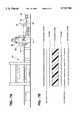
- FIG. 1is an end view of the composite article of the invention wherein the outer portion of a glass fiber reinforced lower reinforcing layer has exposed segments that are not encapsulated by the binder or matrix in which the remainder of the glass fiber reinforcing material is embedded and, also showing fastening means prior to their being affixed to a surface of the reinforcing layer;
- FIG. 2is an end view of the composite article of the invention shown in FIG. 1, showing the fastening means after they have been affixed to the unencapsulated segments of the reinforcing layer;
- FIG. 3is an end view of the composite article of the invention having the entire lower glass fiber reinforcing layer encapsulated by the binder, but wherein the binder encapsulation has been selectively removed from localized areas to which the fastening means have been affixed to the surface of the reinforcing layer during the affixation process carried out by spin welding;
- FIG. 4is an end view of another embodiment of the composite article of the invention, similar to those shown in FIGS. 2 and 3, but having a decorative foam/scrim layer adhesively affixed to both reinforcing layers;
- FIG. 5is an end view of the composite article of the invention as shown in FIG. 2, attached to a supporting structure;
- FIG. 6is an end view of a prior art structure showing the fastening means adapted to extend through an aperture provided in the composite panel and used to attach the panel to a supporting structure;
- FIGS. 7A and Bis a schematic representation of the process of making the composite article of the invention to which the fastening means are subsequently affixed.
- the present inventionpertains to the utilization of foam core materials that are used in trim panels.
- foam core materialsthat are used in trim panels.
- Such techniques for preparing such foam core materialsare well known in the art. See, for example, U.S. Pat. Nos. 5,308,678; 5,068,001; and 5,393,474, hereby incorporated by reference.
- the article 20is relatively lightweight and flexible. It comprises a foam core 22 having reinforcing layers 24 and 25 located on the surfaces or sides of the foam core 22.
- the reinforcing layers 24 and 25are preferably made of glass fibers.
- An adhesive layer or film 28is applied over the reinforcing layer 24 and is used to bond an outer surface layer 26 to the reinforcing layer 24.
- the outer surface layer 26comprises the exterior surface of the composite article 20 of the present invention and is utilized for decorative purposes.
- the foam core 22can be of uniform thickness and can be made from soft, flexible sheets of any suitable expanded, reticulated or open cell plastic material such as a polyether, polyolefin, polyester, polyurethane, or any combination thereof.
- the foam core 22is impregnated or saturated with a catalyst-activated, heat accelerated liquid hardening binder which enters and fills the cells of the foam, coating the cell walls.
- the binder resinsuch as isocyanate
- the binder resincompletely permeates and encapsulates the reinforcing layer 24 which serves as the outer layer of the composite article.
- the binder resinonly permeates a limited portion of the reinforcing layer 25.
- the fibers on the outer surface of the reinforcing layerremain free of the binder resin with it being understood that the segments can be whisker ends, random strand surfaces, or other reinforcing features so long as they are not encapsulated.
- thermoplastic fastener 27when the base 28 of the thermoplastic fastener 27 is melted by spin welding or other means well known in the art, the molten material permeates the segments of the fibers of the reinforcing layer which are free of the binder resin. The thermoplastic material of the fastening means 27 is then permitted to cool and solidify, resulting in very strong affixation or mechanical bond of the base 28 of the fastener 27 to the surface of the composite article 20.
- FIG. 3another embodiment of the invention is shown, in which both of the reinforcing layers 24 are completely encapsulated with the isocyanate thermosetting material.
- a methodsuch as spin welding or vibration welding must be used.
- the binder resinis physically removed from the outer fibers of the reinforcing layer 24, thereby permitting the molten thermoplastic material of the base 28 of the fastener 27 to permeate the free outer fibers of the reinforcing layer 24, and thereafter become strongly affixed to the reinforcing layer 24 when the thermoplastic material is permitted to cool and harden.
- FIG. 4a composite article similar to that of FIG. 3 is shown.
- a foam/scrim 26 and 26ais applied to both surfaces of the composite article.
- a portion of the foam/scrim 26acan be physically removed in the areas where the fasteners 27 are to be affixed.
- FIG. 5a composite article 20 such as shown in FIG. 2 having fasteners 27 affixed to a surface of the article 20, is shown, with the hook 34 and a portion of the shaft 32 extending into a base structure 36 and strongly affixing the composite article 20 to the base structure 36.
- FIG. 6a prior art method of affixing an article 60 formed with a thermosetting material to a base structure 62 is shown.
- the composite article 60is provided with an aperture 64 extending through the entire thickness thereof.
- a fastener 66is inserted in the aperture 64, with the shaft 68 and hook 70 further extending into the base structure 62 and the base 72 of the fastener 66 engaging the outer surface of the composite article 60 and holding it fast.
- the foam core 22is fed from a stock reel which contains foam stock which has been previously sized to the desired thickness.
- the thickness of the foam materialis approximately 7 mm; however, the foam core 22 can be of any thickness and can be varied to meet manufacturing specifications.
- the foam which makes up the foam core 22is unrolled from the stock reel 40 and passes through a binder bath 42 which contains the binder.
- the catalyst activatible liquid binderis preferably polymeric MDI (4-4'-diphenylmethane di-isocyanate).
- isocyanatessuch as TDI (toluene diisocyanate),IPDI (isophoronediisocyanate), phenyl isocyanate, and H 12 MDI may be used as substitutes for the MDI.
- the MDI bindersaturates the foam and through a process of polymerization of the MDI rigidizes the cell walls of the foam core 22 by forming isocyanurate linkages, urethane linkages, urea linkages, trimer linkages, biuret linkages, and/or allophante linkages.
- the binderfunctions as an adhesive to bind together the layers of the composite article.
- the MDI saturated foam 22exits the binder bath 42 and is compressed between a set of calender rolls 44 which are used to control the amount of MDI retained in the foam core 22.
- the amount of MDI saturationis commonly referred to as the saturant level.
- the saturant levelBy controlling the saturant level (amount), it is possible to vary the rigidity of the article 20 produced. Since the degree of rigidity (soft ⁇ hard) of the composite article 20 is a function of both the type and the amount of saturant present, i.e., % MDI, varying the type or the amount of saturant directly effects the rigidity of the composite article 20.
- a composite article 20can be produced having any desired degree of resilience or yieldability. Therefore, a composite article 20 can be produced wherein the foam core 22 provides structural rigidity ranging from very soft (little or no structural support, very resilient) to very rigid (good structural support, not resilient).
- the saturant rangecan be from 300-1500 g(MDI) for 20 mm of foam.
- the foam core 22 with the desired amount of MDIis then treated in a catalyst spray 46 with a polymerization catalyst which catalyzes the polymerization of the isocyanate and water.
- the catalystis sprayed directly onto the MDI impregnated foam core 22 utilizing methods and apparatus known to those skilled in the art.
- Catalysts utilized in the isocyanate chemistryare well known in the art. See, for example, U.S. Pat. No. 5,354,808 hereby incorporated by reference.
- Catalysts that may be utilizedare amine catalysts, the catalysts may also be acids or organic bases. Typical organic bases include triethyl amine, pyridine and the like. While strong acids and Lewis acids may also be utilized.
- Other catalysts that may be usedare organo metallic compounds such as tin derivatives.
- Typical amine catalysts useful in the present inventioninclude triethyl-amine, and those known under the trade names "Dabco” (Air Products and Chemicals), "Niax” (Union Carbide Corporation), “Polycat” (Abbott), and “Thancat” (Jefferson Chemical Company).
- Organometallic compounds useful in catalyzing the reaction of isocyanates with macroglycolsinclude, di-n-butyltin dilaurate, as well as carboxylic acid salts of calcium, cobalt, lead, manganese, zinc, and zirconium employed as cocatalysts with tertiary amines, tin compounds and tin-amine combinations.
- the foam core 22receives a fibrous reinforcing material in the form of a layer or mat of reinforcing fibers.
- the foam core 22can receive one or more layers or mats of fibrous reinforcing material 24.
- Each surface of the foam core 22typically receives a layer or mat of fibrous reinforcing material 24.
- the fibrous material which comprises the reinforcing material 24can be of natural or synthetic material. Natural fibrous materials suitable for use in the reinforcing material 24 include animal or vegetable fibers. Suitable fibers may include glass fibers, synthetic fibers such as Kevlar®, or other synthetic fibers known to those skilled in the art.
- the preferred material for use in the reinforcing layer 24is glass fiber.
- the fibrous reinforcing material 24is necessary in order to provide added strength and stiffness to the composite article 20. Additionally, because the reinforcing material 24 is typically constructed of chopped or random continuous fiber strand material, voids or interstitial spaces are created within the weave of the reinforcing material 24. These voids or interstitial spaces allow the heat accelerated binder compound, i.e., MDI, to flow through the voids or interstitial spaces and permeate and saturate the fibers of the reinforcing material 24. Saturation of the fibers of the reinforcing material 24 with the binder compound allows, upon catalyzation, for formation of a mechanical bond between the foam core 22 and the reinforcing material 24. That is, when the binder compound is catalyzed to form a thermosetting material, the same curing reaction that stiffens the foam core 22 mechanically bonds the reinforcing material 24 to the foam core forming an essentially integral layer.
- an exterior or outer surface layer 26can then be applied to the reinforcing material 24.
- the outer surface layer 26can be any suitable material such as scrim, foam, or plastic sheet.
- the outer surface material 26is chosen with a particular application in mind. That is, should a multi-layered composite panel 20 be required to have impact or energy absorbing characteristics, a foam exterior layer can be applied.
- the scrim materialcan be any suitable material such as a polyester fabric, cellulose, rayon, nylon, propylene, vinyl, olefin, or other suitable thermoplastics known to those skilled in the art.
- the outer surface layer 26can be adhesively bonded directly to the reinforcing material 24 with the same MDI which bonds the reinforcing material 24 to the foam core.
- an additional adhesive layer 29(intermediate layer) is used to bond the exterior or surface layer 26 to the reinforcing material 24.
- the adhesivecan be a film or sheet of a thermoplastic material such as a polyester, polyamide, or ethylacrylic acids (EAA, Dow Chemical) which melts or forms bonds at die molding and polymerization reaction temperatures.
- the adhesive layer 29is applied to the reinforcing material 24 in between the layers of reinforcing material 24 and the exterior or surface layer 26. Under the heat of molding, the adhesive layer 29 melts and forms a bond between the reinforcing material 24 and the exterior or surface layer 26.
- the adhesive layer 29In addition to bonding the exterior or surface layer 26 to the reinforcing material 24, prior to melting, the adhesive layer 29 also serves as an occlusive barrier, preventing migration of the MDI to the exterior or surface layers 26. By preventing the migration of the MDI to the exterior or surface layers 26, i.e., a foam exterior layer, the surface characteristics of the foam exterior layer 26 can be maintained without the influence of the MDI hardening solution.
- the adhesive layer or film 29is positioned over the layers of reinforcing material 24, and finally the surface layer 26 of foam/scrim is applied to complete the formation of the composite article 20.
- Each of the constituents which comprise the multi-layered composite article 20, i.e., the reinforcing material 24, the adhesive layer 29, and the surface layers 26are fed from continuous stock reels (shown in FIG. 2).
- the multi-layered composite 20is then passed through a second set of calender rolls 48 which impregnate the reinforcing material 24 with the MDI, polymerization catalysts, and any other ingredients.
- the continuous length of the multi-layered composite 20is then conveyed through a shearing apparatus 50 which cuts the multi-layered composite 20 to desired length.
- the sheared lengths of the multi-layered composite 20are then placed into a tenter frame (holding frame) (not shown).
- the tentered compositeis then transported to a die press/mold 52.
- the die press/mold 52is maintained at a temperature between 200° F. and 400° F. It is at this temperature that the polymerization reaction occurs, and the foam core 22 becomes a rigid thermosetting plastic.
- the multi-layered composite 20is pressed between male and female die halves to reproduce the configuration of the final article to be made such as automotive interior trim components e.g., headliners, dashboards, armrests, etc.
- the die pressed or molded multi-layered composite article 20is then allowed to cure for between 15 to 90 seconds and is then removed the press/mold 52 for trimming and other post assembly processing.
- Polyurea multi-layer compositesare constructed by the following method.
- the methodincludes impregnating a sheet of open cell material, such as foam, with an isocyanate having at least one terminal --NCO group. Water is then applied to the isocyanate impregnated open celled material to cause the formation of the urea and biuret urethane linkages and impart rigidity to the composite article.
- Layers of reinforcing materialcan be applied over the open celled material to add additional strength to the composite article.
- surface layerssuch as scrim or foam can be applied over the reinforcing material either with or without the use of an additional adhesive material.
- the composite materialcan then be molded under heat and pressure to cure the urethane reaction and form the rigid composite article.
- the upper layer of reinforcing material 24is completely encapsulated by the polyurethane thermosetting resin to affix the adhesive layer 29 to the foam layer 22, and a foam/scrim layer 26 is adhesively applied to the surface of the reinforcing material 24.
- a lower layer of reinforcing material 25is only partially encapsulated, only sufficiently to affix the lower layer of reinforcing material 25 to the foam layer 22, but leaving the outer fibers of the reinforcing layer 25a free of the polyurethane thermosetting resin.
- thermoplastic material of the fasteners 27can permeate and infiltrate the free fibers of the reinforcing material 25a and become affixed thereto when the thermoplastic material becomes solidified.
- the spin welding processin addition to melting the base of the fastener, also results in simultaneously physically removing the urethane thermosetting resin from the outer fibers of the reinforcing material 24.
- the molten thermoplastic material of the fastener 27can then permeate the free fibers of the reinforcing material 24 and become affixed thereto.
- the panel prepared by the spin welding technique as described hereindoes not utilize its separate application of an adhesive to secure fasteners.
- spin weldingis a well known technique for adhering plastic materials to each other. See, for example, U.S. Pat. Nos. 3,779,446; 3,993,519; 5,255,485; 4,987,714; 4,636,124; 4,599,768; 4,551,189; 5,064,485; 4,457,795; 5,108,539; and 4,075,820. These patents are hereby incorporated by reference.
- Suitable thermoplastic for construction of the fasteners 27include polyamide as nylon, acetal, polycarbonates, polyvinyl chloride, PC/ABS, polystyrenes, polyethylenes, polypropylene, acrylonitrile-butadiene-styrene (ABS) and the like.
Landscapes
- Engineering & Computer Science (AREA)
- Mechanical Engineering (AREA)
- Laminated Bodies (AREA)
Abstract
Description
Claims (13)
Priority Applications (3)
| Application Number | Priority Date | Filing Date | Title |
|---|---|---|---|
| US08/576,252US5725704A (en) | 1995-12-21 | 1995-12-21 | Process for the production of a multi-layer composite article having fasteners affixed to a surface thereof and the article produced thereby |
| PCT/US1996/018010WO1997023338A1 (en) | 1995-12-21 | 1996-11-12 | Multi-layer composite having fastener and method of making |
| US08/881,698US5853842A (en) | 1995-12-21 | 1997-06-25 | Process for the production of a multi-layer composite article having fasteners affixed to a surface thereof and the article produced thereby |
Applications Claiming Priority (1)
| Application Number | Priority Date | Filing Date | Title |
|---|---|---|---|
| US08/576,252US5725704A (en) | 1995-12-21 | 1995-12-21 | Process for the production of a multi-layer composite article having fasteners affixed to a surface thereof and the article produced thereby |
Related Child Applications (1)
| Application Number | Title | Priority Date | Filing Date |
|---|---|---|---|
| US08/881,698DivisionUS5853842A (en) | 1995-12-21 | 1997-06-25 | Process for the production of a multi-layer composite article having fasteners affixed to a surface thereof and the article produced thereby |
Publications (1)
| Publication Number | Publication Date |
|---|---|
| US5725704Atrue US5725704A (en) | 1998-03-10 |
Family
ID=24303605
Family Applications (2)
| Application Number | Title | Priority Date | Filing Date |
|---|---|---|---|
| US08/576,252Expired - LifetimeUS5725704A (en) | 1995-12-21 | 1995-12-21 | Process for the production of a multi-layer composite article having fasteners affixed to a surface thereof and the article produced thereby |
| US08/881,698Expired - Fee RelatedUS5853842A (en) | 1995-12-21 | 1997-06-25 | Process for the production of a multi-layer composite article having fasteners affixed to a surface thereof and the article produced thereby |
Family Applications After (1)
| Application Number | Title | Priority Date | Filing Date |
|---|---|---|---|
| US08/881,698Expired - Fee RelatedUS5853842A (en) | 1995-12-21 | 1997-06-25 | Process for the production of a multi-layer composite article having fasteners affixed to a surface thereof and the article produced thereby |
Country Status (2)
| Country | Link |
|---|---|
| US (2) | US5725704A (en) |
| WO (1) | WO1997023338A1 (en) |
Cited By (9)
| Publication number | Priority date | Publication date | Assignee | Title |
|---|---|---|---|---|
| US6153035A (en)* | 1999-02-12 | 2000-11-28 | The Boeing Company | Method and apparatus for securing a thermoplastic insert within a sandwich panel |
| US20030038408A1 (en)* | 2000-12-22 | 2003-02-27 | Axel Schulte | Method for producing adhesive closure parts |
| US20040220690A1 (en)* | 2003-05-02 | 2004-11-04 | Graham Packaging Company, L.P. | Method and apparatus for creating textured handle packaging |
| US20040222562A1 (en)* | 2003-05-05 | 2004-11-11 | Kirchner Grant David | Rapid thermoform pressure forming process and apparatus |
| US20070102112A1 (en)* | 2005-11-02 | 2007-05-10 | Grabowski Richard M | Self-forming structures |
| DE102006003220A1 (en)* | 2006-01-24 | 2007-07-26 | HÄNSEL VERBUNDTECHNIK GmbH | Production of laminated molding for use in vehicle interior e.g. as self-supporting roof lining involves pressing preform of isocyanate-filled flexible foam between glass fiber layers and barrier layers of nonwoven, adhesive and film |
| US20100180407A1 (en)* | 2009-01-20 | 2010-07-22 | Rocha Gerald | Method And Apparatus For Producing Hook Fasteners |
| US8745827B2 (en) | 2010-07-16 | 2014-06-10 | Gerald ROCHA | Dimensionally flexible touch fastener strip |
| US20190242135A1 (en)* | 2018-02-05 | 2019-08-08 | Carlisle Construction Materials, LLC | Attaching hook film to insulation board |
Families Citing this family (6)
| Publication number | Priority date | Publication date | Assignee | Title |
|---|---|---|---|---|
| US7422783B2 (en)* | 2004-11-24 | 2008-09-09 | Velcro Industries B.V. | Submerged hooks |
| US7108814B2 (en)* | 2004-11-24 | 2006-09-19 | Velcro Industries B.V. | Molded touch fasteners and methods of manufacture |
| US8034430B2 (en) | 2005-10-27 | 2011-10-11 | Kimberly-Clark Worldwide, Inc. | Nonwoven fabric and fastening system that include an auto-adhesive material |
| DE102007031604A1 (en)* | 2007-07-06 | 2009-01-08 | Dr. Ing. H.C. F. Porsche Aktiengesellschaft | Cylindrical and plate or disk shaped workpieces connecting method, involves removing thermosetting material from fibers under sectional exposure of fibers, where melted thermoplastic compound is in contact with exposed fibers after removal |
| DE102015007921A1 (en)* | 2015-06-20 | 2016-12-22 | Daimler Ag | Composite component for a vehicle, in particular a motor vehicle, and method for producing a composite component |
| US20240326919A1 (en)* | 2023-03-30 | 2024-10-03 | GM Global Technology Operations LLC | Paintable fiber-reinforced composite panel |
Citations (31)
| Publication number | Priority date | Publication date | Assignee | Title |
|---|---|---|---|---|
| US2684320A (en)* | 1950-09-12 | 1954-07-20 | Briggs Mfg Co | Trim panel and method of making the same |
| US3019152A (en)* | 1957-04-29 | 1962-01-30 | United Carr Fastener Corp | Apparatus for applying snap fastener elements to supporting materials |
| US3639195A (en)* | 1966-09-20 | 1972-02-01 | Ici Ltd | Bonded fibrous materials and method for making them |
| US3779446A (en)* | 1971-10-13 | 1973-12-18 | J Lemelson | Welding apparatus |
| US3993519A (en)* | 1975-11-07 | 1976-11-23 | Olsen Manufacturing Company, Inc. | Spin welding apparatus and method |
| US3996082A (en)* | 1975-08-14 | 1976-12-07 | William C. Heller, Jr. | Composite bonding method and means |
| US4075820A (en)* | 1976-07-28 | 1978-02-28 | Abbott Laboratories | Spin welding apparatus |
| US4451310A (en)* | 1981-04-14 | 1984-05-29 | Nobel-Bozel | Preparation of lightweight, insulating and semirigid or rigid elements |
| US4457795A (en)* | 1982-05-27 | 1984-07-03 | Baxter Travenol Laboratories, Inc. | Method and apparatus for spin welding soft, flexible thermoplastics |
| US4477307A (en)* | 1982-12-06 | 1984-10-16 | Illinois Tool Works Inc. | Friction welded fastener system |
| US4551189A (en)* | 1984-12-12 | 1985-11-05 | Illinois Tool Works Inc. | Friction welded fastener system |
| US4599768A (en)* | 1985-05-13 | 1986-07-15 | Illinois Tool Works Inc. | Spin welded fastening assembly |
| US4615084A (en)* | 1984-08-21 | 1986-10-07 | Erblok Associates | Multiple hook fastener media and method and system for making |
| US4626308A (en)* | 1983-02-18 | 1986-12-02 | The Victaulic Company Plc | Method of making welded pipe joints |
| US4636124A (en)* | 1985-05-06 | 1987-01-13 | Illinois Tool Works Inc. | Adhesive friction weld fastener |
| US4652415A (en)* | 1985-02-11 | 1987-03-24 | General Motors Corporation | Method of manufacture of a molded friction pad |
| US4676707A (en)* | 1983-01-31 | 1987-06-30 | Illinois Tool Works Inc. | Friction welded fastener system |
| US4780035A (en)* | 1986-07-23 | 1988-10-25 | Nifco, Inc. | Rotary welding member made of resin |
| US4832549A (en)* | 1986-07-23 | 1989-05-23 | Nifco, Inc. | Rotary welding member made of resin |
| US4987714A (en)* | 1988-08-25 | 1991-01-29 | Lemke Stuart H | Method for installing a roof fastener |
| US5026445A (en)* | 1990-05-11 | 1991-06-25 | Branson Ultrasonics Corporation | Method and apparatus for producing carpeted panels |
| US5033925A (en)* | 1988-12-16 | 1991-07-23 | The B. F. Goodrich Company | Composite nut and bolt |
| US5064485A (en)* | 1990-04-23 | 1991-11-12 | Shell Oil Company | Method for the resilient spinwelding of thermoplastic articles |
| US5068001A (en)* | 1987-12-16 | 1991-11-26 | Reinhold Haussling | Method of making a sound absorbing laminate |
| US5089328A (en)* | 1988-02-26 | 1992-02-18 | Van Dresser Corporation | Panel and method of making the same |
| US5108539A (en)* | 1990-04-23 | 1992-04-28 | Shell Oil Company | Apparatus for the resilient spinwelding of thermoplastic articles |
| US5255485A (en)* | 1988-08-25 | 1993-10-26 | Stuart H. Lemke | Apparatus and method for installing roofing fasteners |
| US5308678A (en)* | 1991-10-16 | 1994-05-03 | Ikeda Bussan Co., Ltd. | Trim board |
| US5354808A (en)* | 1992-12-08 | 1994-10-11 | Minnesota Mining And Manufacturing Company | Polyurethanes including pendant hindered amines and compositions incorporating same |
| US5393474A (en)* | 1993-08-19 | 1995-02-28 | Davidson Textron Inc. | Method for molding a shaped plastic trim panel |
| US5494542A (en)* | 1994-11-09 | 1996-02-27 | Davidson Textron Inc. | Method of making vacuum formed article with integrally joined device |
Family Cites Families (2)
| Publication number | Priority date | Publication date | Assignee | Title |
|---|---|---|---|---|
| JPH0779810A (en)* | 1993-08-25 | 1995-03-28 | Minnesota Mining & Mfg Co <3M> | Opposite interlocking zipper member and production thereof |
| US6027798A (en)* | 1995-11-01 | 2000-02-22 | The Boeing Company | Pin-reinforced sandwich structure |
- 1995
- 1995-12-21USUS08/576,252patent/US5725704A/ennot_activeExpired - Lifetime
- 1996
- 1996-11-12WOPCT/US1996/018010patent/WO1997023338A1/enactiveApplication Filing
- 1997
- 1997-06-25USUS08/881,698patent/US5853842A/ennot_activeExpired - Fee Related
Patent Citations (31)
| Publication number | Priority date | Publication date | Assignee | Title |
|---|---|---|---|---|
| US2684320A (en)* | 1950-09-12 | 1954-07-20 | Briggs Mfg Co | Trim panel and method of making the same |
| US3019152A (en)* | 1957-04-29 | 1962-01-30 | United Carr Fastener Corp | Apparatus for applying snap fastener elements to supporting materials |
| US3639195A (en)* | 1966-09-20 | 1972-02-01 | Ici Ltd | Bonded fibrous materials and method for making them |
| US3779446A (en)* | 1971-10-13 | 1973-12-18 | J Lemelson | Welding apparatus |
| US3996082A (en)* | 1975-08-14 | 1976-12-07 | William C. Heller, Jr. | Composite bonding method and means |
| US3993519A (en)* | 1975-11-07 | 1976-11-23 | Olsen Manufacturing Company, Inc. | Spin welding apparatus and method |
| US4075820A (en)* | 1976-07-28 | 1978-02-28 | Abbott Laboratories | Spin welding apparatus |
| US4451310A (en)* | 1981-04-14 | 1984-05-29 | Nobel-Bozel | Preparation of lightweight, insulating and semirigid or rigid elements |
| US4457795A (en)* | 1982-05-27 | 1984-07-03 | Baxter Travenol Laboratories, Inc. | Method and apparatus for spin welding soft, flexible thermoplastics |
| US4477307A (en)* | 1982-12-06 | 1984-10-16 | Illinois Tool Works Inc. | Friction welded fastener system |
| US4676707A (en)* | 1983-01-31 | 1987-06-30 | Illinois Tool Works Inc. | Friction welded fastener system |
| US4626308A (en)* | 1983-02-18 | 1986-12-02 | The Victaulic Company Plc | Method of making welded pipe joints |
| US4615084A (en)* | 1984-08-21 | 1986-10-07 | Erblok Associates | Multiple hook fastener media and method and system for making |
| US4551189A (en)* | 1984-12-12 | 1985-11-05 | Illinois Tool Works Inc. | Friction welded fastener system |
| US4652415A (en)* | 1985-02-11 | 1987-03-24 | General Motors Corporation | Method of manufacture of a molded friction pad |
| US4636124A (en)* | 1985-05-06 | 1987-01-13 | Illinois Tool Works Inc. | Adhesive friction weld fastener |
| US4599768A (en)* | 1985-05-13 | 1986-07-15 | Illinois Tool Works Inc. | Spin welded fastening assembly |
| US4780035A (en)* | 1986-07-23 | 1988-10-25 | Nifco, Inc. | Rotary welding member made of resin |
| US4832549A (en)* | 1986-07-23 | 1989-05-23 | Nifco, Inc. | Rotary welding member made of resin |
| US5068001A (en)* | 1987-12-16 | 1991-11-26 | Reinhold Haussling | Method of making a sound absorbing laminate |
| US5089328A (en)* | 1988-02-26 | 1992-02-18 | Van Dresser Corporation | Panel and method of making the same |
| US4987714A (en)* | 1988-08-25 | 1991-01-29 | Lemke Stuart H | Method for installing a roof fastener |
| US5255485A (en)* | 1988-08-25 | 1993-10-26 | Stuart H. Lemke | Apparatus and method for installing roofing fasteners |
| US5033925A (en)* | 1988-12-16 | 1991-07-23 | The B. F. Goodrich Company | Composite nut and bolt |
| US5064485A (en)* | 1990-04-23 | 1991-11-12 | Shell Oil Company | Method for the resilient spinwelding of thermoplastic articles |
| US5108539A (en)* | 1990-04-23 | 1992-04-28 | Shell Oil Company | Apparatus for the resilient spinwelding of thermoplastic articles |
| US5026445A (en)* | 1990-05-11 | 1991-06-25 | Branson Ultrasonics Corporation | Method and apparatus for producing carpeted panels |
| US5308678A (en)* | 1991-10-16 | 1994-05-03 | Ikeda Bussan Co., Ltd. | Trim board |
| US5354808A (en)* | 1992-12-08 | 1994-10-11 | Minnesota Mining And Manufacturing Company | Polyurethanes including pendant hindered amines and compositions incorporating same |
| US5393474A (en)* | 1993-08-19 | 1995-02-28 | Davidson Textron Inc. | Method for molding a shaped plastic trim panel |
| US5494542A (en)* | 1994-11-09 | 1996-02-27 | Davidson Textron Inc. | Method of making vacuum formed article with integrally joined device |
Cited By (21)
| Publication number | Priority date | Publication date | Assignee | Title |
|---|---|---|---|---|
| US6153035A (en)* | 1999-02-12 | 2000-11-28 | The Boeing Company | Method and apparatus for securing a thermoplastic insert within a sandwich panel |
| US7374707B2 (en)* | 2000-12-22 | 2008-05-20 | Gottlieb Binder Gmbh & Co. | Method for producing adhesive closing parts |
| US20030038408A1 (en)* | 2000-12-22 | 2003-02-27 | Axel Schulte | Method for producing adhesive closure parts |
| US20030104137A1 (en)* | 2000-12-22 | 2003-06-05 | Axel Schulte | Method for producing adhesive closing parts |
| US7374706B2 (en)* | 2000-12-22 | 2008-05-20 | Gottlieb Binder Gmbh & Co. | Method for producing adhesive closure parts |
| US20040220690A1 (en)* | 2003-05-02 | 2004-11-04 | Graham Packaging Company, L.P. | Method and apparatus for creating textured handle packaging |
| US20040222562A1 (en)* | 2003-05-05 | 2004-11-11 | Kirchner Grant David | Rapid thermoform pressure forming process and apparatus |
| US7326044B2 (en) | 2003-05-05 | 2008-02-05 | Ortho-Active Holdings Inc. | Rapid thermoform pressure forming process and apparatus |
| US7562503B2 (en) | 2005-11-02 | 2009-07-21 | Grabowski Richard M | Self-forming structures |
| US20070102112A1 (en)* | 2005-11-02 | 2007-05-10 | Grabowski Richard M | Self-forming structures |
| DE102006003220A1 (en)* | 2006-01-24 | 2007-07-26 | HÄNSEL VERBUNDTECHNIK GmbH | Production of laminated molding for use in vehicle interior e.g. as self-supporting roof lining involves pressing preform of isocyanate-filled flexible foam between glass fiber layers and barrier layers of nonwoven, adhesive and film |
| US20100180407A1 (en)* | 2009-01-20 | 2010-07-22 | Rocha Gerald | Method And Apparatus For Producing Hook Fasteners |
| US8784722B2 (en)* | 2009-01-20 | 2014-07-22 | Gerald ROCHA | Method and apparatus for producing hook fasteners |
| US10076162B2 (en) | 2009-01-20 | 2018-09-18 | Gerald ROCHA | Method and apparatus for producing hook fasteners |
| US10798997B2 (en) | 2009-01-20 | 2020-10-13 | Gerald F. Rocha | Method and apparatus for producing hook fasteners |
| US8745827B2 (en) | 2010-07-16 | 2014-06-10 | Gerald ROCHA | Dimensionally flexible touch fastener strip |
| US9795194B2 (en) | 2010-07-16 | 2017-10-24 | Gerald ROCHA | Dimensionally flexible touch fastener strip |
| US10405614B2 (en) | 2010-07-16 | 2019-09-10 | Gerald ROCHA | Dimensionally flexible touch fastener strip |
| US11058186B2 (en) | 2010-07-16 | 2021-07-13 | Gerald ROCHA | Dimensionally flexible touch fastener strip |
| US20190242135A1 (en)* | 2018-02-05 | 2019-08-08 | Carlisle Construction Materials, LLC | Attaching hook film to insulation board |
| US10450755B2 (en)* | 2018-02-05 | 2019-10-22 | Carlisle Construction Materials, LLC | Attaching hook film to insulation board |
Also Published As
| Publication number | Publication date |
|---|---|
| US5853842A (en) | 1998-12-29 |
| WO1997023338A1 (en) | 1997-07-03 |
Similar Documents
| Publication | Publication Date | Title |
|---|---|---|
| US5089328A (en) | Panel and method of making the same | |
| US5725704A (en) | Process for the production of a multi-layer composite article having fasteners affixed to a surface thereof and the article produced thereby | |
| EP0266224B1 (en) | Process for the manufacture of laminated elements | |
| US20110315310A1 (en) | Single press mold process for forming a finished light weight structural component | |
| JPH07232398A (en) | MULTILAYER STRUCTURE MEMBER AND METHOD OF MANUFACTURING THE SAME AND DEVICE | |
| JPS585346A (en) | Preparation of lightweight, insulative, flexible, hard or semi-hard element and element thereby | |
| US20040235378A1 (en) | Vehicle interior trim component of basalt fibers and thermosetting resin and method of manufacturing the same | |
| HUP0202086A2 (en) | Method of producing vehicle interior material having sandwich structure | |
| US20040234744A1 (en) | Vehicle interior trim component of basalt fibers and thermoplastic binder and method of manufacturing the same | |
| MX2010012439A (en) | Foam laminate product and process for production thereof. | |
| JPH0218039A (en) | Inner packaging composite base raw material and panel | |
| JP2004155193A (en) | Method for producing decorative board for lining | |
| JP2779895B2 (en) | Interior material and manufacturing method thereof | |
| EP0342768B1 (en) | Process for the production of a light weight sandwich structure | |
| JP2753636B2 (en) | Vehicle interior material and method of manufacturing the same | |
| JP4036701B2 (en) | Molded interior material and manufacturing method thereof | |
| JP2000210910A (en) | Automotive interior trim base material | |
| AU620440B2 (en) | Method for the manufacture of laminated elements | |
| EP1531116A2 (en) | Method for producing a reinforcing and soundproofing panel for vehicule roofs, reinforcing member obtained from such method and use of a two component polyurethane compound for producing said reinforcing member | |
| WO1996036676A1 (en) | Process for production of multi-layer composite article | |
| JPH055000Y2 (en) | ||
| US20220219410A1 (en) | Panel for a vehicle | |
| JPH02208040A (en) | Production of base material for interior material | |
| JPH11170924A (en) | Bracket mounting method and press molding die | |
| JPH0751292B2 (en) | Method for producing polyurethane foam molded article |
Legal Events
| Date | Code | Title | Description |
|---|---|---|---|
| AS | Assignment | Owner name:DAVIDSON TEXTRON, INC., DELAWARE Free format text:ASSIGNMENT OF ASSIGNORS INTEREST;ASSIGNORS:SOUDERS, STEVEN;GALLAGHER, MICHAEL;REEL/FRAME:007921/0652;SIGNING DATES FROM 19960321 TO 19960322 | |
| STCF | Information on status: patent grant | Free format text:PATENTED CASE | |
| FEPP | Fee payment procedure | Free format text:PAYOR NUMBER ASSIGNED (ORIGINAL EVENT CODE: ASPN); ENTITY STATUS OF PATENT OWNER: LARGE ENTITY | |
| FPAY | Fee payment | Year of fee payment:4 | |
| AS | Assignment | Owner name:JPMORGAN CHASE BANK, AS COLLATERAL AGENT, TEXAS Free format text:SECURITY AGREEMENT;ASSIGNOR:TEXTRON AUTOMOTIVE INTERIORS INC.;REEL/FRAME:012676/0848 Effective date:20011220 | |
| FPAY | Fee payment | Year of fee payment:8 | |
| AS | Assignment | Owner name:TEXTRON AUTOMOTIVE INTERIORS INC., MICHIGAN Free format text:CHANGE OF NAME;ASSIGNOR:DAVIDSON TEXTRON INC.;REEL/FRAME:019265/0102 Effective date:19941229 Owner name:COLLINS & ALKMAN AUTOMOTIVE INTERIORS, INC., MICHI Free format text:CHANGE OF NAME;ASSIGNOR:TEXTRON AUTOMOTIVE INTERIORS INC.;REEL/FRAME:019458/0365 Effective date:20020703 | |
| AS | Assignment | Owner name:COLLINS & AIKMAN PRODUCTS LLC, MICHIGAN Free format text:NUNC PRO TUNC ASSIGNMENT;ASSIGNOR:COLLINS & AIKMAN AUTOMOTIVE INTERIORS, LLC;REEL/FRAME:021462/0845 Effective date:20080807 | |
| FEPP | Fee payment procedure | Free format text:PAYER NUMBER DE-ASSIGNED (ORIGINAL EVENT CODE: RMPN); ENTITY STATUS OF PATENT OWNER: LARGE ENTITY Free format text:PAYOR NUMBER ASSIGNED (ORIGINAL EVENT CODE: ASPN); ENTITY STATUS OF PATENT OWNER: LARGE ENTITY | |
| REMI | Maintenance fee reminder mailed | ||
| FPAY | Fee payment | Year of fee payment:12 | |
| SULP | Surcharge for late payment | Year of fee payment:11 |