US5725587A - Acetabular cup assembly - Google Patents
Acetabular cup assemblyDownload PDFInfo
- Publication number
- US5725587A US5725587AUS08/572,459US57245995AUS5725587AUS 5725587 AUS5725587 AUS 5725587AUS 57245995 AUS57245995 AUS 57245995AUS 5725587 AUS5725587 AUS 5725587A
- Authority
- US
- United States
- Prior art keywords
- shell
- bearing
- bearing component
- recess
- component
- Prior art date
- Legal status (The legal status is an assumption and is not a legal conclusion. Google has not performed a legal analysis and makes no representation as to the accuracy of the status listed.)
- Expired - Lifetime
Links
- 238000003780insertionMethods0.000claimsdescription5
- 230000037431insertionEffects0.000claimsdescription5
- 238000000034methodMethods0.000claimsdescription3
- 230000013011matingEffects0.000abstractdescription2
- 230000007246mechanismEffects0.000description8
- 210000001624hipAnatomy0.000description2
- 238000003754machiningMethods0.000description2
- 239000004698PolyethyleneSubstances0.000description1
- 238000011882arthroplastyMethods0.000description1
- 230000000712assemblyEffects0.000description1
- 238000000429assemblyMethods0.000description1
- 238000010009beatingMethods0.000description1
- 210000004394hip jointAnatomy0.000description1
- 238000004519manufacturing processMethods0.000description1
- 239000002184metalSubstances0.000description1
- -1polyethylenePolymers0.000description1
- 229920000573polyethylenePolymers0.000description1
- 238000001356surgical procedureMethods0.000description1
Images


Classifications
- A—HUMAN NECESSITIES
- A61—MEDICAL OR VETERINARY SCIENCE; HYGIENE
- A61F—FILTERS IMPLANTABLE INTO BLOOD VESSELS; PROSTHESES; DEVICES PROVIDING PATENCY TO, OR PREVENTING COLLAPSING OF, TUBULAR STRUCTURES OF THE BODY, e.g. STENTS; ORTHOPAEDIC, NURSING OR CONTRACEPTIVE DEVICES; FOMENTATION; TREATMENT OR PROTECTION OF EYES OR EARS; BANDAGES, DRESSINGS OR ABSORBENT PADS; FIRST-AID KITS
- A61F2/00—Filters implantable into blood vessels; Prostheses, i.e. artificial substitutes or replacements for parts of the body; Appliances for connecting them with the body; Devices providing patency to, or preventing collapsing of, tubular structures of the body, e.g. stents
- A61F2/02—Prostheses implantable into the body
- A61F2/30—Joints
- A61F2/46—Special tools for implanting artificial joints
- A61F2/4637—Special tools for implanting artificial joints for connecting or disconnecting two parts of a prosthesis
- A—HUMAN NECESSITIES
- A61—MEDICAL OR VETERINARY SCIENCE; HYGIENE
- A61F—FILTERS IMPLANTABLE INTO BLOOD VESSELS; PROSTHESES; DEVICES PROVIDING PATENCY TO, OR PREVENTING COLLAPSING OF, TUBULAR STRUCTURES OF THE BODY, e.g. STENTS; ORTHOPAEDIC, NURSING OR CONTRACEPTIVE DEVICES; FOMENTATION; TREATMENT OR PROTECTION OF EYES OR EARS; BANDAGES, DRESSINGS OR ABSORBENT PADS; FIRST-AID KITS
- A61F2/00—Filters implantable into blood vessels; Prostheses, i.e. artificial substitutes or replacements for parts of the body; Appliances for connecting them with the body; Devices providing patency to, or preventing collapsing of, tubular structures of the body, e.g. stents
- A61F2/02—Prostheses implantable into the body
- A61F2/30—Joints
- A61F2/32—Joints for the hip
- A61F2/34—Acetabular cups
- A—HUMAN NECESSITIES
- A61—MEDICAL OR VETERINARY SCIENCE; HYGIENE
- A61F—FILTERS IMPLANTABLE INTO BLOOD VESSELS; PROSTHESES; DEVICES PROVIDING PATENCY TO, OR PREVENTING COLLAPSING OF, TUBULAR STRUCTURES OF THE BODY, e.g. STENTS; ORTHOPAEDIC, NURSING OR CONTRACEPTIVE DEVICES; FOMENTATION; TREATMENT OR PROTECTION OF EYES OR EARS; BANDAGES, DRESSINGS OR ABSORBENT PADS; FIRST-AID KITS
- A61F2/00—Filters implantable into blood vessels; Prostheses, i.e. artificial substitutes or replacements for parts of the body; Appliances for connecting them with the body; Devices providing patency to, or preventing collapsing of, tubular structures of the body, e.g. stents
- A61F2/02—Prostheses implantable into the body
- A61F2/30—Joints
- A61F2/30767—Special external or bone-contacting surface, e.g. coating for improving bone ingrowth
- A—HUMAN NECESSITIES
- A61—MEDICAL OR VETERINARY SCIENCE; HYGIENE
- A61F—FILTERS IMPLANTABLE INTO BLOOD VESSELS; PROSTHESES; DEVICES PROVIDING PATENCY TO, OR PREVENTING COLLAPSING OF, TUBULAR STRUCTURES OF THE BODY, e.g. STENTS; ORTHOPAEDIC, NURSING OR CONTRACEPTIVE DEVICES; FOMENTATION; TREATMENT OR PROTECTION OF EYES OR EARS; BANDAGES, DRESSINGS OR ABSORBENT PADS; FIRST-AID KITS
- A61F2/00—Filters implantable into blood vessels; Prostheses, i.e. artificial substitutes or replacements for parts of the body; Appliances for connecting them with the body; Devices providing patency to, or preventing collapsing of, tubular structures of the body, e.g. stents
- A61F2/02—Prostheses implantable into the body
- A61F2/30—Joints
- A61F2002/30001—Additional features of subject-matter classified in A61F2/28, A61F2/30 and subgroups thereof
- A61F2002/30316—The prosthesis having different structural features at different locations within the same prosthesis; Connections between prosthetic parts; Special structural features of bone or joint prostheses not otherwise provided for
- A61F2002/30329—Connections or couplings between prosthetic parts, e.g. between modular parts; Connecting elements
- A61F2002/30331—Connections or couplings between prosthetic parts, e.g. between modular parts; Connecting elements made by longitudinally pushing a protrusion into a complementarily-shaped recess, e.g. held by friction fit
- A61F2002/30378—Spherically-shaped protrusion and recess
- A—HUMAN NECESSITIES
- A61—MEDICAL OR VETERINARY SCIENCE; HYGIENE
- A61F—FILTERS IMPLANTABLE INTO BLOOD VESSELS; PROSTHESES; DEVICES PROVIDING PATENCY TO, OR PREVENTING COLLAPSING OF, TUBULAR STRUCTURES OF THE BODY, e.g. STENTS; ORTHOPAEDIC, NURSING OR CONTRACEPTIVE DEVICES; FOMENTATION; TREATMENT OR PROTECTION OF EYES OR EARS; BANDAGES, DRESSINGS OR ABSORBENT PADS; FIRST-AID KITS
- A61F2/00—Filters implantable into blood vessels; Prostheses, i.e. artificial substitutes or replacements for parts of the body; Appliances for connecting them with the body; Devices providing patency to, or preventing collapsing of, tubular structures of the body, e.g. stents
- A61F2/02—Prostheses implantable into the body
- A61F2/30—Joints
- A61F2002/30001—Additional features of subject-matter classified in A61F2/28, A61F2/30 and subgroups thereof
- A61F2002/30316—The prosthesis having different structural features at different locations within the same prosthesis; Connections between prosthetic parts; Special structural features of bone or joint prostheses not otherwise provided for
- A61F2002/30329—Connections or couplings between prosthetic parts, e.g. between modular parts; Connecting elements
- A61F2002/30476—Connections or couplings between prosthetic parts, e.g. between modular parts; Connecting elements locked by an additional locking mechanism
- A61F2002/30495—Connections or couplings between prosthetic parts, e.g. between modular parts; Connecting elements locked by an additional locking mechanism using a locking ring
- A—HUMAN NECESSITIES
- A61—MEDICAL OR VETERINARY SCIENCE; HYGIENE
- A61F—FILTERS IMPLANTABLE INTO BLOOD VESSELS; PROSTHESES; DEVICES PROVIDING PATENCY TO, OR PREVENTING COLLAPSING OF, TUBULAR STRUCTURES OF THE BODY, e.g. STENTS; ORTHOPAEDIC, NURSING OR CONTRACEPTIVE DEVICES; FOMENTATION; TREATMENT OR PROTECTION OF EYES OR EARS; BANDAGES, DRESSINGS OR ABSORBENT PADS; FIRST-AID KITS
- A61F2/00—Filters implantable into blood vessels; Prostheses, i.e. artificial substitutes or replacements for parts of the body; Appliances for connecting them with the body; Devices providing patency to, or preventing collapsing of, tubular structures of the body, e.g. stents
- A61F2/02—Prostheses implantable into the body
- A61F2/30—Joints
- A61F2/30767—Special external or bone-contacting surface, e.g. coating for improving bone ingrowth
- A61F2/30771—Special external or bone-contacting surface, e.g. coating for improving bone ingrowth applied in original prostheses, e.g. holes or grooves
- A61F2002/3082—Grooves
- A—HUMAN NECESSITIES
- A61—MEDICAL OR VETERINARY SCIENCE; HYGIENE
- A61F—FILTERS IMPLANTABLE INTO BLOOD VESSELS; PROSTHESES; DEVICES PROVIDING PATENCY TO, OR PREVENTING COLLAPSING OF, TUBULAR STRUCTURES OF THE BODY, e.g. STENTS; ORTHOPAEDIC, NURSING OR CONTRACEPTIVE DEVICES; FOMENTATION; TREATMENT OR PROTECTION OF EYES OR EARS; BANDAGES, DRESSINGS OR ABSORBENT PADS; FIRST-AID KITS
- A61F2/00—Filters implantable into blood vessels; Prostheses, i.e. artificial substitutes or replacements for parts of the body; Appliances for connecting them with the body; Devices providing patency to, or preventing collapsing of, tubular structures of the body, e.g. stents
- A61F2/02—Prostheses implantable into the body
- A61F2/30—Joints
- A61F2/32—Joints for the hip
- A61F2002/3208—Bipolar or multipolar joints, e.g. having a femoral head articulating within an intermediate acetabular shell whilst said shell articulates within the natural acetabular socket or within an artificial outer shell
- A—HUMAN NECESSITIES
- A61—MEDICAL OR VETERINARY SCIENCE; HYGIENE
- A61F—FILTERS IMPLANTABLE INTO BLOOD VESSELS; PROSTHESES; DEVICES PROVIDING PATENCY TO, OR PREVENTING COLLAPSING OF, TUBULAR STRUCTURES OF THE BODY, e.g. STENTS; ORTHOPAEDIC, NURSING OR CONTRACEPTIVE DEVICES; FOMENTATION; TREATMENT OR PROTECTION OF EYES OR EARS; BANDAGES, DRESSINGS OR ABSORBENT PADS; FIRST-AID KITS
- A61F2/00—Filters implantable into blood vessels; Prostheses, i.e. artificial substitutes or replacements for parts of the body; Appliances for connecting them with the body; Devices providing patency to, or preventing collapsing of, tubular structures of the body, e.g. stents
- A61F2/02—Prostheses implantable into the body
- A61F2/30—Joints
- A61F2/32—Joints for the hip
- A61F2002/3233—Joints for the hip having anti-luxation means for preventing complete dislocation of the femoral head from the acetabular cup
- A—HUMAN NECESSITIES
- A61—MEDICAL OR VETERINARY SCIENCE; HYGIENE
- A61F—FILTERS IMPLANTABLE INTO BLOOD VESSELS; PROSTHESES; DEVICES PROVIDING PATENCY TO, OR PREVENTING COLLAPSING OF, TUBULAR STRUCTURES OF THE BODY, e.g. STENTS; ORTHOPAEDIC, NURSING OR CONTRACEPTIVE DEVICES; FOMENTATION; TREATMENT OR PROTECTION OF EYES OR EARS; BANDAGES, DRESSINGS OR ABSORBENT PADS; FIRST-AID KITS
- A61F2/00—Filters implantable into blood vessels; Prostheses, i.e. artificial substitutes or replacements for parts of the body; Appliances for connecting them with the body; Devices providing patency to, or preventing collapsing of, tubular structures of the body, e.g. stents
- A61F2/02—Prostheses implantable into the body
- A61F2/30—Joints
- A61F2/32—Joints for the hip
- A61F2002/3241—Joints for the hip having a ring, e.g. for locking the femoral head into the acetabular cup
- A—HUMAN NECESSITIES
- A61—MEDICAL OR VETERINARY SCIENCE; HYGIENE
- A61F—FILTERS IMPLANTABLE INTO BLOOD VESSELS; PROSTHESES; DEVICES PROVIDING PATENCY TO, OR PREVENTING COLLAPSING OF, TUBULAR STRUCTURES OF THE BODY, e.g. STENTS; ORTHOPAEDIC, NURSING OR CONTRACEPTIVE DEVICES; FOMENTATION; TREATMENT OR PROTECTION OF EYES OR EARS; BANDAGES, DRESSINGS OR ABSORBENT PADS; FIRST-AID KITS
- A61F2/00—Filters implantable into blood vessels; Prostheses, i.e. artificial substitutes or replacements for parts of the body; Appliances for connecting them with the body; Devices providing patency to, or preventing collapsing of, tubular structures of the body, e.g. stents
- A61F2/02—Prostheses implantable into the body
- A61F2/30—Joints
- A61F2/32—Joints for the hip
- A61F2/34—Acetabular cups
- A61F2002/3401—Acetabular cups with radial apertures, e.g. radial bores for receiving fixation screws
- A—HUMAN NECESSITIES
- A61—MEDICAL OR VETERINARY SCIENCE; HYGIENE
- A61F—FILTERS IMPLANTABLE INTO BLOOD VESSELS; PROSTHESES; DEVICES PROVIDING PATENCY TO, OR PREVENTING COLLAPSING OF, TUBULAR STRUCTURES OF THE BODY, e.g. STENTS; ORTHOPAEDIC, NURSING OR CONTRACEPTIVE DEVICES; FOMENTATION; TREATMENT OR PROTECTION OF EYES OR EARS; BANDAGES, DRESSINGS OR ABSORBENT PADS; FIRST-AID KITS
- A61F2/00—Filters implantable into blood vessels; Prostheses, i.e. artificial substitutes or replacements for parts of the body; Appliances for connecting them with the body; Devices providing patency to, or preventing collapsing of, tubular structures of the body, e.g. stents
- A61F2/02—Prostheses implantable into the body
- A61F2/30—Joints
- A61F2/32—Joints for the hip
- A61F2/34—Acetabular cups
- A61F2002/3443—Acetabular cups with an anti-luxation elevated rim portion, e.g. on the inner shell
- A—HUMAN NECESSITIES
- A61—MEDICAL OR VETERINARY SCIENCE; HYGIENE
- A61F—FILTERS IMPLANTABLE INTO BLOOD VESSELS; PROSTHESES; DEVICES PROVIDING PATENCY TO, OR PREVENTING COLLAPSING OF, TUBULAR STRUCTURES OF THE BODY, e.g. STENTS; ORTHOPAEDIC, NURSING OR CONTRACEPTIVE DEVICES; FOMENTATION; TREATMENT OR PROTECTION OF EYES OR EARS; BANDAGES, DRESSINGS OR ABSORBENT PADS; FIRST-AID KITS
- A61F2/00—Filters implantable into blood vessels; Prostheses, i.e. artificial substitutes or replacements for parts of the body; Appliances for connecting them with the body; Devices providing patency to, or preventing collapsing of, tubular structures of the body, e.g. stents
- A61F2/02—Prostheses implantable into the body
- A61F2/30—Joints
- A61F2/32—Joints for the hip
- A61F2/34—Acetabular cups
- A61F2002/348—Additional features
- A61F2002/3493—Spherical shell significantly greater than a hemisphere, e.g. extending over more than 200 degrees
- A—HUMAN NECESSITIES
- A61—MEDICAL OR VETERINARY SCIENCE; HYGIENE
- A61F—FILTERS IMPLANTABLE INTO BLOOD VESSELS; PROSTHESES; DEVICES PROVIDING PATENCY TO, OR PREVENTING COLLAPSING OF, TUBULAR STRUCTURES OF THE BODY, e.g. STENTS; ORTHOPAEDIC, NURSING OR CONTRACEPTIVE DEVICES; FOMENTATION; TREATMENT OR PROTECTION OF EYES OR EARS; BANDAGES, DRESSINGS OR ABSORBENT PADS; FIRST-AID KITS
- A61F2220/00—Fixations or connections for prostheses classified in groups A61F2/00 - A61F2/26 or A61F2/82 or A61F9/00 or A61F11/00 or subgroups thereof
- A61F2220/0025—Connections or couplings between prosthetic parts, e.g. between modular parts; Connecting elements
- A61F2220/0033—Connections or couplings between prosthetic parts, e.g. between modular parts; Connecting elements made by longitudinally pushing a protrusion into a complementary-shaped recess, e.g. held by friction fit
Definitions
- This inventionrelates to an acetabular cup assembly, and has specific relevance to the mechanism used to secure the bearing component to the shell component.
- Prosthetic acetabular cup assembliesare well known in the medical industry for replacing a portion of a patient's hip joint during total hip arthroplasty.
- the acetabular cup assemblyincludes a metal shell and a polyethylene bearing component.
- the bearing componentsare secured within the shell components by a variety of mechanisms.
- U.S. Pat. Nos. 5,171,285 and 5,383,938disclose the use of a snap or lock ring to secure being liners within cup shells.
- U.S. Pat. No. 5,282,864 to Noiles et al.discloses the use of threaded screws to seat the bearing liner within the shell.
- Each of these securement mechanismsrequire additional components and manufacturing to the completed cup assembly.
- the acetabular cup assembly of this inventionuses the mating contour of the bearing component and shell component to provide a reliable interlocking engagement, which secures the bearing component to the shell component. No additional components, such as snap rings or fasteners are necessary to secure the bearing component to the shell component. However, such additional securing components could be used if additional securement is desired.
- the interlocking engagement used to secure the components of this inventionrequires less machining and fabricating. The secure interlocking engagement of the bearing and shell may help reduce micromotion between the components.
- the cup assemblyincludes a shell component and bearing component.
- the bearing componentis generally hemispherical in shape and includes a convex spherical surface and an end surface.
- the convex bearing surfaceextends beyond its lateral diametrical plane, making the shape of the bearing component slightly greater than a hemisphere.
- the shell componenthas a cotyloid shape and includes a spherical concave inner surface defining an open cavity for receiving the bearing component.
- the concave shell surfaceis complimentary and approximately the same in contour and radial dimension to the convex bearing surface.
- the concave shell surfaceincludes an annular portion, which extends beyond its lateral diametrical plane. Consequently, the diameter at the mouth of the shell cavity is less than the over all lateral diameter of the shell cavity.
- the concave shell surfacealso has a diametrical recess.
- the diametrical recessmay be a single continuous diametrical recess extending from one side of the inner edge of the shell rim to the opposite side of the inner edge of the shell rim.
- the dimetrical recessmay be a discontinuous diametrical recess including at least two portions, one extending from one side of the inner edge of the shell rim and the other extending from the opposite side of the inner edge of the shell rim, with both portions diametrically aligned with each other.
- the bearing componentcan not be inserted directly into the shell cavity, because its lateral diameter is greater than the diameter at the mouth of the shell cavity.
- the diametrical recess in the concave shell surfaceallows the bearing component to be inserted into the shell cavity in a sideways position. With the bearing component rotated 90° about a lateral diametrical axis so that the end surface of the bearing component, which may be a substantially flat end or which may include an elevated lip on the end surface, is substantially perpendicular to the diametrical plane of the concave shell surface and substantially parallel to the recess, the bearing component can be inserted in the shell cavity.
- the depth and width of the recessallows sufficient lateral clearance for the bearing component in this sideways position.
- the bearing componentcan be rotated back 90° about its diametrical axis within the shell cavity so that the convex bearing surface is seated concentrically over the concave shell surface.
- the annular portion of the concave shell surfaceconverges partially over the bearing component to secure the bearing component within the shell cavity.
- an advantage of the acetabular cup assembly of this inventionis that the components are self-interlocking while requiring minimal machining or fabricating.
- Another advantage of the present inventionis that no instruments are needed to facilitate the securement of the liner within the shell, thereby reducing the instrument count of the surgical procedure; however, a suitable assembly instrument could be provided if desired.
- Another advantage of the present inventionis that no snap ring is needed to lock the liner in place within the shell; although, a typical lock ring, or other suitable stop-type mechanism could be used in conjunction with the present invention for additional securement, if desired.
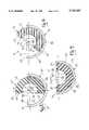
- FIG. 1is a perspective view of the cup assembly using the locking mechanism of this invention showing the bearing liner positioned for insertion above the shell component;
- FIG. 2is a side sectional view of the cup assembly of FIG. 1 showing the bearing liner positioned for insertion above the shell component;
- FIG. 3is a side sectional view of the cup assembly showing the bearing liner inserted into the shell component in its initial position;
- FIG. 4is a side sectional view of the cup assembly showing the bearing liner pivoting within the shell component
- FIG. 5is a side sectional view of the cup assembly showing the bearing liner secured in its locked position within the shell component;
- FIG. 6is a perspective view of an alternate embodiment of the cup assembly and locking mechanism of this invention showing the bearing liner positioned for insertion above the shell component;
- FIG. 7is a side sectional view of the cup assembly of FIG. 6 showing the bearing liner pivoting within the shell component.
- the modular acetabular cup assembly 10 of this inventionis illustrated in the figures as including a bearing component 20 and a cup or shell component 30.
- Bearing component 20is generally hemispherical in shape and includes a convex spherical surface 22 and a flat end surface 24.
- the locus of spherical bearing surface 22is equidistant from a center point B.
- convex bearing surface 22extends beyond its lateral diametrical plane 23, making the shape of bearing component 20 slightly greater than a hemisphere.
- End surface 24has a central opening 25 and a chamfered edge 26 around opening 25 for receiving the head of a conventional hip stem (not shown).
- Shell component 30has a cotyloid shape and includes a convex outer surface 32, a spherical concave inner surface 36 and an annular rim 34 defining an open cavity 37 for receiving bearing component 20.
- Concave shell surface 36also has a diametrical recess 40.
- concave shell surface 36is equidistant from a center point S and is approximately the same in contour and radial dimension to convex bearing surface 22.
- Concave shell surface 36includes an annular portion 38 adjacent rim 34, which extends beyond its lateral diametrical plane 39. Consequently, the contour of shell cavity 37 is shaped slightly greater than a hemisphere and is approximately the same as the shape of bearing component 20. Since, annular portion 38 of concave shell surface 36 converges slightly, the diameter at the mouth of shell cavity 37 is less than the over all lateral diameter of the shell cavity.
- FIGS. 2-5illustrate the procedure for affixing bearing component 20 to shell component 30 within shell cavity 37.
- Beating component 20can not be inserted directly into shell cavity 37, because its lateral diameter is greater than the diameter at the mouth of shell cavity 37.
- shell recess 40allows bearing component 20 to be inserted into shell cavity 37 in a sideways position.
- bearing component 20is rotated 90° about a lateral diametrical axis so that end surface 24 is substantially perpendicular to diametrical plane 39 and positioned substantially parallel to recess 40.
- the diametrical recess 40is a single continuous diametrical recess extending from one side of the inner edge of the shell rim 34 to the opposite side of the inner edge of the shell rim.
- the depth and width of recess 40allows sufficient lateral clearance for bearing component 20 in this sideways position.
- center point B of convex bearing surface 22is located at center point S of concave shell surface 36 when bearing component 20 is inserted into shell cavity 37.
- annular portion 38 of concave shell surface 36provides a secure interlocking engagement of the bearing component
- a conventional lock ring mechanismmay also be incorporated into the design of the cup assembly for additional securement, if desired.
- Such a lock ring 102is shown in the alternate embodiment of the cup assembly 100 in FIGS. 6 and 7. This cup assembly utilizes a lock ring 102, such as the type described in U.S. Pat. No. 5,383,938, which is incorporated herein by reference. Alternate additional securing mechanisms may also be incorporated, as desired.
- cup assembly 100includes a diametrical recess 400 which is a discontinuous diametrical recess, including two portions 402, one extending from one side of the inner edge of the shell rim 340 of shell 300 and the other extending from the opposite side of the inner edge of the shell rim, with both portions 402 diametrically aligned with each other.
- the depth and width and length of recess portions 402allows sufficient lateral clearance for bearing component 200 to be inserted into the shell 300 in a sideways position.
- bearing component 200shows an end surface 240 with an elevated rim 242 shown thereon.
- elevated rimsare known in the art.
- the bearing component 200, with elevated rim 242would be inserted into shell 300 with the side opposite the rim 242 being inserted first into the shell in a sideways position.
- the bearing component 200is shown in FIG. 7 being rotated or pivoted toward its final position (not shown) in which the lock ring 102 will engage bearing 200 to further secure the assembly of the bearing 200 and shell 300.
- the outer surface of the shellmay include a porous surface or the shell may include through holes therein. Although these options are not shown, they are well known in the art.
Landscapes
- Health & Medical Sciences (AREA)
- Orthopedic Medicine & Surgery (AREA)
- Transplantation (AREA)
- Vascular Medicine (AREA)
- Oral & Maxillofacial Surgery (AREA)
- Engineering & Computer Science (AREA)
- Biomedical Technology (AREA)
- Heart & Thoracic Surgery (AREA)
- Cardiology (AREA)
- Life Sciences & Earth Sciences (AREA)
- Animal Behavior & Ethology (AREA)
- General Health & Medical Sciences (AREA)
- Public Health (AREA)
- Veterinary Medicine (AREA)
- Physical Education & Sports Medicine (AREA)
- Prostheses (AREA)
Abstract
Description
This invention relates to an acetabular cup assembly, and has specific relevance to the mechanism used to secure the bearing component to the shell component.
Prosthetic acetabular cup assemblies are well known in the medical industry for replacing a portion of a patient's hip joint during total hip arthroplasty. Generally the acetabular cup assembly includes a metal shell and a polyethylene bearing component. The bearing components are secured within the shell components by a variety of mechanisms. For example, U.S. Pat. Nos. 5,171,285 and 5,383,938 disclose the use of a snap or lock ring to secure being liners within cup shells. U.S. Pat. No. 5,282,864 to Noiles et al. discloses the use of threaded screws to seat the bearing liner within the shell. Each of these securement mechanisms require additional components and manufacturing to the completed cup assembly.
The acetabular cup assembly of this invention uses the mating contour of the bearing component and shell component to provide a reliable interlocking engagement, which secures the bearing component to the shell component. No additional components, such as snap rings or fasteners are necessary to secure the bearing component to the shell component. However, such additional securing components could be used if additional securement is desired. In addition, the interlocking engagement used to secure the components of this invention requires less machining and fabricating. The secure interlocking engagement of the bearing and shell may help reduce micromotion between the components.
The cup assembly includes a shell component and bearing component. The bearing component is generally hemispherical in shape and includes a convex spherical surface and an end surface. The convex bearing surface extends beyond its lateral diametrical plane, making the shape of the bearing component slightly greater than a hemisphere. The shell component has a cotyloid shape and includes a spherical concave inner surface defining an open cavity for receiving the bearing component. The concave shell surface is complimentary and approximately the same in contour and radial dimension to the convex bearing surface. The concave shell surface includes an annular portion, which extends beyond its lateral diametrical plane. Consequently, the diameter at the mouth of the shell cavity is less than the over all lateral diameter of the shell cavity. The concave shell surface also has a diametrical recess. The diametrical recess may be a single continuous diametrical recess extending from one side of the inner edge of the shell rim to the opposite side of the inner edge of the shell rim. Alternatively, the dimetrical recess may be a discontinuous diametrical recess including at least two portions, one extending from one side of the inner edge of the shell rim and the other extending from the opposite side of the inner edge of the shell rim, with both portions diametrically aligned with each other.
The bearing component can not be inserted directly into the shell cavity, because its lateral diameter is greater than the diameter at the mouth of the shell cavity. The diametrical recess in the concave shell surface allows the bearing component to be inserted into the shell cavity in a sideways position. With the bearing component rotated 90° about a lateral diametrical axis so that the end surface of the bearing component, which may be a substantially flat end or which may include an elevated lip on the end surface, is substantially perpendicular to the diametrical plane of the concave shell surface and substantially parallel to the recess, the bearing component can be inserted in the shell cavity. The depth and width of the recess allows sufficient lateral clearance for the bearing component in this sideways position. Once inserted in the shell cavity in a sideways position, the bearing component can be rotated back 90° about its diametrical axis within the shell cavity so that the convex bearing surface is seated concentrically over the concave shell surface. When the bearing component is rotated to this final position, the annular portion of the concave shell surface converges partially over the bearing component to secure the bearing component within the shell cavity.
Accordingly, an advantage of the acetabular cup assembly of this invention is that the components are self-interlocking while requiring minimal machining or fabricating.
Another advantage of the present invention is that no instruments are needed to facilitate the securement of the liner within the shell, thereby reducing the instrument count of the surgical procedure; however, a suitable assembly instrument could be provided if desired.
Another advantage of the present invention is that no snap ring is needed to lock the liner in place within the shell; although, a typical lock ring, or other suitable stop-type mechanism could be used in conjunction with the present invention for additional securement, if desired.
Other advantages will become apparent upon a reading of the following description.
A preferred embodiment of the invention has been depicted for illustrative purposes only wherein:
FIG. 1 is a perspective view of the cup assembly using the locking mechanism of this invention showing the bearing liner positioned for insertion above the shell component;
FIG. 2 is a side sectional view of the cup assembly of FIG. 1 showing the bearing liner positioned for insertion above the shell component;
FIG. 3 is a side sectional view of the cup assembly showing the bearing liner inserted into the shell component in its initial position;
FIG. 4 is a side sectional view of the cup assembly showing the bearing liner pivoting within the shell component;
FIG. 5 is a side sectional view of the cup assembly showing the bearing liner secured in its locked position within the shell component;
FIG. 6 is a perspective view of an alternate embodiment of the cup assembly and locking mechanism of this invention showing the bearing liner positioned for insertion above the shell component; and
FIG. 7 is a side sectional view of the cup assembly of FIG. 6 showing the bearing liner pivoting within the shell component.
The preferred embodiment herein described is not intended to be exhaustive or to limit the invention to the precise form disclosed. It is chosen and described to explain the principles of the invention and its application and practical use to enable others skilled in the art to utilize its teachings.
The modularacetabular cup assembly 10 of this invention is illustrated in the figures as including abearing component 20 and a cup orshell component 30.Bearing component 20 is generally hemispherical in shape and includes a convexspherical surface 22 and aflat end surface 24. The locus of spherical bearingsurface 22 is equidistant from a center point B. As shown best in FIG. 2, convex bearingsurface 22 extends beyond its lateraldiametrical plane 23, making the shape ofbearing component 20 slightly greater than a hemisphere.End surface 24 has acentral opening 25 and a chamferededge 26 around opening 25 for receiving the head of a conventional hip stem (not shown).Shell component 30 has a cotyloid shape and includes a convexouter surface 32, a spherical concaveinner surface 36 and anannular rim 34 defining anopen cavity 37 for receivingbearing component 20.Concave shell surface 36 also has adiametrical recess 40. As shown in the FIGS. 2-5,concave shell surface 36 is equidistant from a center point S and is approximately the same in contour and radial dimension to convex bearingsurface 22.Concave shell surface 36 includes anannular portion 38adjacent rim 34, which extends beyond its lateraldiametrical plane 39. Consequently, the contour ofshell cavity 37 is shaped slightly greater than a hemisphere and is approximately the same as the shape ofbearing component 20. Since,annular portion 38 ofconcave shell surface 36 converges slightly, the diameter at the mouth ofshell cavity 37 is less than the over all lateral diameter of the shell cavity.
FIGS. 2-5 illustrate the procedure for affixing bearingcomponent 20 toshell component 30 withinshell cavity 37. Beatingcomponent 20 can not be inserted directly intoshell cavity 37, because its lateral diameter is greater than the diameter at the mouth ofshell cavity 37. As shown in FIG. 2,shell recess 40 allowsbearing component 20 to be inserted intoshell cavity 37 in a sideways position. As shown in FIGS. 2 and 3,bearing component 20 is rotated 90° about a lateral diametrical axis so thatend surface 24 is substantially perpendicular todiametrical plane 39 and positioned substantially parallel to recess 40. Thediametrical recess 40 is a single continuous diametrical recess extending from one side of the inner edge of theshell rim 34 to the opposite side of the inner edge of the shell rim. The depth and width ofrecess 40 allows sufficient lateral clearance forbearing component 20 in this sideways position. As shown in FIGS. 3-5, center point B of convex bearingsurface 22 is located at center point S ofconcave shell surface 36 when bearingcomponent 20 is inserted intoshell cavity 37. With the lateral edge of bearingcomponent 20 inserted withinrecess 40, the bearing component is rotated back 90° about a diametrical axis through center points B,S so thatconvex bearing surface 22 is seated concentrically overconcave shell surface 36 andbearing end face 24 is flush withshell rim 34. When bearingcomponent 20 is rotated to this final position,annular portion 38 ofconcave shell surface 36 converges partially over bearingcomponent 20 to secure the bearing component withinshell cavity 37. One skilled in the art will note that the dimensional tolerances ofconcave shell surface 36 andspherical bearing surface 22 are critical to a secure concentric engagement betweenbearing component 20 andshell component 30.
Whileannular portion 38 ofconcave shell surface 36 provides a secure interlocking engagement of the bearing component, a conventional lock ring mechanism may also be incorporated into the design of the cup assembly for additional securement, if desired. Such alock ring 102 is shown in the alternate embodiment of thecup assembly 100 in FIGS. 6 and 7. This cup assembly utilizes alock ring 102, such as the type described in U.S. Pat. No. 5,383,938, which is incorporated herein by reference. Alternate additional securing mechanisms may also be incorporated, as desired.
In addition,cup assembly 100 includes adiametrical recess 400 which is a discontinuous diametrical recess, including twoportions 402, one extending from one side of the inner edge of theshell rim 340 ofshell 300 and the other extending from the opposite side of the inner edge of the shell rim, with bothportions 402 diametrically aligned with each other. The depth and width and length ofrecess portions 402 allows sufficient lateral clearance for bearingcomponent 200 to be inserted into theshell 300 in a sideways position.
Also,bearing component 200 shows anend surface 240 with anelevated rim 242 shown thereon. Such elevated rims are known in the art. Thebearing component 200, withelevated rim 242, would be inserted intoshell 300 with the side opposite therim 242 being inserted first into the shell in a sideways position. Thebearing component 200 is shown in FIG. 7 being rotated or pivoted toward its final position (not shown) in which thelock ring 102 will engage bearing 200 to further secure the assembly of thebearing 200 andshell 300.
It is also noted that the outer surface of the shell may include a porous surface or the shell may include through holes therein. Although these options are not shown, they are well known in the art.
It is understood that the above description does not limit the invention to the details given, but may be modified within the scope of the following claims.
Claims (9)
1. A modular acetabular cup assembly comprising:
a shell component including a concave spherical surface terminating in an annular rim to define an open inner cavity, said shell concave surface having a recess defined therein and an annular surface portion extending radially beyond the lateral diametrical plane of said shell concave surface, and
a bearing component including an end surface and a convex spherical surface having a contour complimentary to said shell concave surface for concentric engagement therewith,
said bearing component being insertable into said shell inner cavity in a first position wherein the lateral diametrical plane of said bearing convex surface is sideways or not parallel to the lateral diametrical plane of said shell concave surface and said bearing end surface is positioned over said recess for insertion therein, and being rotatable within said shell inner cavity to a second position wherein said bearing convex surface is seated concentrically over said shell concave surface and said shell surface portion converges partially over said bearing component to secure said bearing component within said shell inner cavity.
2. The cup assembly of claim 1 wherein said recess is a single continuous recess extending from a one inner side of the rim to an opposite inner side of the rim.
3. The cup assembly of claim 1 wherein said recess is a discontinuous recess including at least two portions, a first recess portion extending from a one inner side of the rim and a second recess portion extending from an opposite inner side of the rim, the first and second recess portions being diametrically aligned.
4. The cup assembly of claim 1 wherein said shell rim and said bearing end surface substantially planarly align when said bearing component is seated within said shell cavity in said second position.
5. The cup assembly of claim 1 wherein said bearing concave surface extends radially beyond its lateral diametrical plane.
6. The cup assembly of claim 1 wherein said assembly includes an additional securing means between the shell component and the bearing component.
7. The cup assembly of claim 1 wherein said end surface of said bearing component includes an elevated rim on a portion of the end surface.
8. A modular acetabular cup assembly comprising:
a shell component including a concave spherical surface terminating in an annular rim to define an open inner cavity, said shell concave surface having a diametrical recess defined therein and an annular surface portion extending radially beyond the lateral diametrical plane of said shell concave surface, and
a bearing component including an end surface and a convex spherical surface having a contour complimentary to said shell concave surface for concentric engagement therewith,
said bearing component being insertable into said shell inner cavity in a first position wherein the lateral diametrical plane of said bearing convex surface is substantially perpendicular to the lateral diametrical plane of said shell concave surface and said bearing end surface is positioned over and substantially parallel to said recess, and being rotatable within said shell inner cavity to a second position wherein said bearing convex surface is seated concentrically over said shell concave surface and said shell surface portion converges partially over said bearing component to secure said bearing component within said shell inner cavity.
9. A method of assembling a modular cup assembly wherein said assembly comprises a shell component including a concave spherical surface terminating in an annular rim to define an open inner cavity, said shell concave surface having a recess defined therein and an annular surface portion extending radially beyond the lateral diametrical plane of said shell concave surface, and a bearing component including an end surface and a convex spherical surface having a contour complimentary to said shell concave surface for concentric engagement therewith, and wherein the method comprises:
inserting said bearing component into said shell inner cavity in a first position wherein the lateral diametrical plane of said bearing convex surface is sideways or not parallel to the lateral diametrical plane of said shell concave surface, and said bearing end surface is positioned over said recess for insertion therein; and
rotating said bearing component within said inner cavity to a second position wherein said bearing convex surface is seated concentrically over said shell concave surface and said shell surface portion converges partially over said bearing component to secure said bearing component within said shell inner cavity.
Priority Applications (1)
| Application Number | Priority Date | Filing Date | Title |
|---|---|---|---|
| US08/572,459US5725587A (en) | 1995-12-14 | 1995-12-14 | Acetabular cup assembly |
Applications Claiming Priority (1)
| Application Number | Priority Date | Filing Date | Title |
|---|---|---|---|
| US08/572,459US5725587A (en) | 1995-12-14 | 1995-12-14 | Acetabular cup assembly |
Publications (1)
| Publication Number | Publication Date |
|---|---|
| US5725587Atrue US5725587A (en) | 1998-03-10 |
Family
ID=24287893
Family Applications (1)
| Application Number | Title | Priority Date | Filing Date |
|---|---|---|---|
| US08/572,459Expired - LifetimeUS5725587A (en) | 1995-12-14 | 1995-12-14 | Acetabular cup assembly |
Country Status (1)
| Country | Link |
|---|---|
| US (1) | US5725587A (en) |
Cited By (29)
| Publication number | Priority date | Publication date | Assignee | Title |
|---|---|---|---|---|
| FR2785524A1 (en)* | 1998-11-10 | 2000-05-12 | Serf Sa | Plastics socket for hip joint prosthesis has cup with spherical joint surface and necked cylindrical opening |
| US20030065382A1 (en)* | 2001-10-02 | 2003-04-03 | Fischell Robert E. | Means and method for the treatment of coronary artery obstructions |
| US20030187512A1 (en)* | 2002-04-01 | 2003-10-02 | Phil Frederick | Liner assembly for prosthetic components |
| WO2002058597A3 (en)* | 2001-01-25 | 2003-10-30 | Smith & Nephew Inc | Containment system for constraining a prosthetic component |
| US20040030402A1 (en)* | 2002-08-08 | 2004-02-12 | Uri Arnin | Elastomeric covers for orthopedic implants |
| US20040054418A1 (en)* | 2002-09-13 | 2004-03-18 | Mclean Terry | Prostheses |
| US20050075735A1 (en)* | 2000-04-10 | 2005-04-07 | Berelsman Brian K. | Method and apparatus for adjusting height and angle for a radial head |
| US20050240276A1 (en)* | 2004-03-11 | 2005-10-27 | Shea Jeffrey J | Universal liner |
| EP1611869A1 (en)* | 2004-06-30 | 2006-01-04 | DePuy Products, Inc. | Extended radius prosthesis |
| US20060241781A1 (en)* | 2005-04-21 | 2006-10-26 | Biomet Manufacturing Corp. | Method and apparatus for use of porous implants |
| US20060241776A1 (en)* | 2005-04-21 | 2006-10-26 | Biomet Manufacturing Corp. | Method and apparatus for use of porous implants |
| US20070173948A1 (en)* | 2005-04-21 | 2007-07-26 | Biomet Manufacturing Corp. | Porous metal cup with cobalt bearing surface |
| US20070196230A1 (en)* | 2006-02-17 | 2007-08-23 | Biomet Manufacturing Corp. | Method and apparatus for forming porous metal implants |
| US20080147187A1 (en)* | 2005-04-21 | 2008-06-19 | Biomet Manufacturing Corp. | Method And Apparatus For Use Of Porous Implants |
| US20090084491A1 (en)* | 2007-09-25 | 2009-04-02 | Biomet Manufacturing Corp. | Cementless Tibial Tray |
| US7572294B2 (en) | 2007-03-07 | 2009-08-11 | Biomet Manufacturing Corp. | Method and apparatus for removing an acetabular bearing |
| US20100063589A1 (en)* | 2006-11-17 | 2010-03-11 | Scyon Orthopaedics Ag | Wear-reducing geometry of articulations in total joint replacements |
| US20100131073A1 (en)* | 2008-11-24 | 2010-05-27 | Biomet Manufacturing Corp. | Multiple Bearing Acetabular Prosthesis |
| US20100241236A1 (en)* | 2000-04-10 | 2010-09-23 | Biomet Manufacturing Corp. | Modular Radial Head Prosthesis |
| US20110015752A1 (en)* | 2009-07-14 | 2011-01-20 | Biomet Manufacturing Corp. | System and Method for Acetabular Cup |
| JP2011087712A (en)* | 2009-10-21 | 2011-05-06 | Univ Of Tokyo | Liner for artificial hip joint and artificial hip joint using the same |
| US8021432B2 (en) | 2005-12-05 | 2011-09-20 | Biomet Manufacturing Corp. | Apparatus for use of porous implants |
| US8123814B2 (en) | 2001-02-23 | 2012-02-28 | Biomet Manufacturing Corp. | Method and appartus for acetabular reconstruction |
| US8308810B2 (en) | 2009-07-14 | 2012-11-13 | Biomet Manufacturing Corp. | Multiple bearing acetabular prosthesis |
| US8535382B2 (en) | 2000-04-10 | 2013-09-17 | Biomet Manufacturing, Llc | Modular radial head prostheses |
| US8679187B2 (en) | 2006-03-20 | 2014-03-25 | Smith & Nephew, Inc. | Acetabular cup assembly for multiple bearing materials |
| US8700198B2 (en) | 2010-06-08 | 2014-04-15 | Smith & Nephew, Inc. | Implant components and methods |
| US20200046505A1 (en)* | 2009-07-10 | 2020-02-13 | Peter Mats Forsell | Hip joint device and method |
| US11033395B2 (en) | 2017-02-02 | 2021-06-15 | Howmedica Osteonics Corp. | Constrained shell for modular dual mobility system |
Citations (14)
| Publication number | Priority date | Publication date | Assignee | Title |
|---|---|---|---|---|
| US3813699A (en)* | 1973-01-15 | 1974-06-04 | R Giliberty | Prosthetic hip joint |
| US3916451A (en)* | 1974-10-25 | 1975-11-04 | Frederick F Buechel | Floating center prosthetic joint |
| US4172296A (en)* | 1978-02-01 | 1979-10-30 | Howmedica, Inc. | Bicentric joint prosthesis |
| US4279041A (en)* | 1978-07-06 | 1981-07-21 | Buchholz Hans Wilhelm | Endoprosthesis composed of a socket and a head receivable and lockable in the socket |
| US4624674A (en)* | 1982-02-24 | 1986-11-25 | Pappas Michael J | Spherical kinematic joint |
| US4718911A (en)* | 1986-02-19 | 1988-01-12 | Pfizer Hospital Products Group Inc. | Acetabular cup assembly |
| US4770659A (en)* | 1984-03-07 | 1988-09-13 | Kendall Richard L | Femoral prosthesis with forced motion sharing |
| US5074881A (en)* | 1989-03-17 | 1991-12-24 | Roger Thull | Hip joint socket for implantation without cement into the acetabulum of the hip bone |
| US5171285A (en)* | 1992-02-18 | 1992-12-15 | Zimmer, Inc. | Acetabular cup with shiftable elevated rim liner |
| US5222984A (en)* | 1990-03-15 | 1993-06-29 | Forte Mark R | Implantable acetabular prosthetic hip joint with universal adjustability |
| US5282864A (en)* | 1992-02-19 | 1994-02-01 | Joint Medical Products Corporation | Acetabular prosthesis having a metal socket bearing |
| US5314487A (en)* | 1991-02-14 | 1994-05-24 | Smith & Nephew Richards Inc. | Acetabular prosthesis with anchoring pegs |
| US5358532A (en)* | 1992-06-16 | 1994-10-25 | Smith & Nephew Richards Inc. | Cementless acetabular cup |
| US5383938A (en)* | 1993-02-12 | 1995-01-24 | Zimmer, Inc. | Locking ring for an acetabular cup |
- 1995
- 1995-12-14USUS08/572,459patent/US5725587A/ennot_activeExpired - Lifetime
Patent Citations (14)
| Publication number | Priority date | Publication date | Assignee | Title |
|---|---|---|---|---|
| US3813699A (en)* | 1973-01-15 | 1974-06-04 | R Giliberty | Prosthetic hip joint |
| US3916451A (en)* | 1974-10-25 | 1975-11-04 | Frederick F Buechel | Floating center prosthetic joint |
| US4172296A (en)* | 1978-02-01 | 1979-10-30 | Howmedica, Inc. | Bicentric joint prosthesis |
| US4279041A (en)* | 1978-07-06 | 1981-07-21 | Buchholz Hans Wilhelm | Endoprosthesis composed of a socket and a head receivable and lockable in the socket |
| US4624674A (en)* | 1982-02-24 | 1986-11-25 | Pappas Michael J | Spherical kinematic joint |
| US4770659A (en)* | 1984-03-07 | 1988-09-13 | Kendall Richard L | Femoral prosthesis with forced motion sharing |
| US4718911A (en)* | 1986-02-19 | 1988-01-12 | Pfizer Hospital Products Group Inc. | Acetabular cup assembly |
| US5074881A (en)* | 1989-03-17 | 1991-12-24 | Roger Thull | Hip joint socket for implantation without cement into the acetabulum of the hip bone |
| US5222984A (en)* | 1990-03-15 | 1993-06-29 | Forte Mark R | Implantable acetabular prosthetic hip joint with universal adjustability |
| US5314487A (en)* | 1991-02-14 | 1994-05-24 | Smith & Nephew Richards Inc. | Acetabular prosthesis with anchoring pegs |
| US5171285A (en)* | 1992-02-18 | 1992-12-15 | Zimmer, Inc. | Acetabular cup with shiftable elevated rim liner |
| US5282864A (en)* | 1992-02-19 | 1994-02-01 | Joint Medical Products Corporation | Acetabular prosthesis having a metal socket bearing |
| US5358532A (en)* | 1992-06-16 | 1994-10-25 | Smith & Nephew Richards Inc. | Cementless acetabular cup |
| US5383938A (en)* | 1993-02-12 | 1995-01-24 | Zimmer, Inc. | Locking ring for an acetabular cup |
Cited By (83)
| Publication number | Priority date | Publication date | Assignee | Title |
|---|---|---|---|---|
| FR2785524A1 (en)* | 1998-11-10 | 2000-05-12 | Serf Sa | Plastics socket for hip joint prosthesis has cup with spherical joint surface and necked cylindrical opening |
| US8425615B2 (en) | 2000-04-10 | 2013-04-23 | Biomet Manufacturing Corp. | Method and apparatus for adjusting height and angle for a radial head |
| US8366781B2 (en) | 2000-04-10 | 2013-02-05 | Biomet Manufacturing Corp. | Modular prosthesis and use thereof for replacing a radial head |
| US20100262252A1 (en)* | 2000-04-10 | 2010-10-14 | Biomet Manufacturing Corp. | Modular prosthesis and use thereof for replacing a radial head |
| US20100312349A1 (en)* | 2000-04-10 | 2010-12-09 | Biomet Manufacturing Corp. | Modular prosthesis and use thereof for replacing a radial head |
| US9579208B2 (en) | 2000-04-10 | 2017-02-28 | Biomet Manufacturing, Llc | Modular radial head prosthesis |
| US20050075735A1 (en)* | 2000-04-10 | 2005-04-07 | Berelsman Brian K. | Method and apparatus for adjusting height and angle for a radial head |
| US20110125276A1 (en)* | 2000-04-10 | 2011-05-26 | Biomet Manufacturing Corp. | Modular prosthesis and use thereof for replacing a radial head |
| US9439784B2 (en) | 2000-04-10 | 2016-09-13 | Biomet Manufacturing, Llc | Modular radial head prosthesis |
| US20100030339A1 (en)* | 2000-04-10 | 2010-02-04 | Biomet Manufacturing Corp. | Method and apparatus for adjusting height and angle for a radial head |
| US20110144759A1 (en)* | 2000-04-10 | 2011-06-16 | Biomet Manufacturing Corp. | Modular prosthesis and use thereof for replacing a radial head |
| US9333084B2 (en) | 2000-04-10 | 2016-05-10 | Biomet Manufacturing, Llc | Modular prosthesis and use thereof for replacing a radial head |
| US8920509B2 (en) | 2000-04-10 | 2014-12-30 | Biomet Manufacturing, Llc | Modular radial head prosthesis |
| US8110005B2 (en) | 2000-04-10 | 2012-02-07 | Biomet Manufacturing Corp. | Modular prosthesis and use thereof for replacing a radial head |
| US8114163B2 (en) | 2000-04-10 | 2012-02-14 | Biomet Manufacturing Corp. | Method and apparatus for adjusting height and angle for a radial head |
| US8535382B2 (en) | 2000-04-10 | 2013-09-17 | Biomet Manufacturing, Llc | Modular radial head prostheses |
| US20100241236A1 (en)* | 2000-04-10 | 2010-09-23 | Biomet Manufacturing Corp. | Modular Radial Head Prosthesis |
| US8029572B2 (en) | 2001-01-25 | 2011-10-04 | Smith & Nephew, Inc. | Containment system for constraining a prosthetic component |
| US8029571B2 (en) | 2001-01-25 | 2011-10-04 | Smith & Nephew, Inc. | Containment system for constraining a prosthetic component |
| US20100234963A1 (en)* | 2001-01-25 | 2010-09-16 | Smith & Nephew, Inc. | Containment system for constraining a prosthetic component |
| US7749277B2 (en) | 2001-01-25 | 2010-07-06 | Smith & Nephew, Inc. | Containment system for constraining a prosthetic component |
| US7335231B2 (en) | 2001-01-25 | 2008-02-26 | Smith & Nephew, Inc. | Containment system for constraining a prosthetic component |
| US20080125866A1 (en)* | 2001-01-25 | 2008-05-29 | Mclean Terry | Containment system for constraining a prosthetic component |
| WO2002058597A3 (en)* | 2001-01-25 | 2003-10-30 | Smith & Nephew Inc | Containment system for constraining a prosthetic component |
| US8790412B2 (en) | 2001-01-25 | 2014-07-29 | Smith & Nephew, Inc. | Containment system for constraining a prosthetic component |
| US8123814B2 (en) | 2001-02-23 | 2012-02-28 | Biomet Manufacturing Corp. | Method and appartus for acetabular reconstruction |
| US9375316B2 (en) | 2001-02-23 | 2016-06-28 | Biomet Manufacturing, Llc. | Method and apparatus for acetabular reconstruction |
| US8551181B2 (en) | 2001-02-23 | 2013-10-08 | Biomet Manufacturing, Llc | Method and apparatus for acetabular reconstruction |
| US20030065382A1 (en)* | 2001-10-02 | 2003-04-03 | Fischell Robert E. | Means and method for the treatment of coronary artery obstructions |
| US20030187512A1 (en)* | 2002-04-01 | 2003-10-02 | Phil Frederick | Liner assembly for prosthetic components |
| US20050246031A1 (en)* | 2002-04-01 | 2005-11-03 | Phil Frederick | Line assembly for prosthetic components |
| US6916342B2 (en) | 2002-04-01 | 2005-07-12 | Smith & Nephew, Inc. | Liner assembly for prosthetic components |
| US7160332B2 (en) | 2002-04-01 | 2007-01-09 | Smith & Nephew, Inc. | Line assembly for prosthetic components |
| US20040030402A1 (en)* | 2002-08-08 | 2004-02-12 | Uri Arnin | Elastomeric covers for orthopedic implants |
| US20080015707A1 (en)* | 2002-09-13 | 2008-01-17 | Richard Lambert | Hip prostheses |
| US8753404B2 (en) | 2002-09-13 | 2014-06-17 | Smith & Nephew, Inc. | Hip prostheses |
| US6986792B2 (en) | 2002-09-13 | 2006-01-17 | Smith & Nephew, Inc. | Prostheses |
| US8603182B2 (en) | 2002-09-13 | 2013-12-10 | Smith & Nephew, Inc. | Hip prostheses |
| US20040054418A1 (en)* | 2002-09-13 | 2004-03-18 | Mclean Terry | Prostheses |
| US20060217814A1 (en)* | 2002-09-13 | 2006-09-28 | Smith & Nephew, Inc. | Hip prostheses |
| US20050240276A1 (en)* | 2004-03-11 | 2005-10-27 | Shea Jeffrey J | Universal liner |
| US7955395B2 (en)* | 2004-03-11 | 2011-06-07 | Smith & Nephew, Inc. | Universal liner |
| JP2006015153A (en)* | 2004-06-30 | 2006-01-19 | Depuy Products Inc | Extended artificial joint and associated method |
| US20060004463A1 (en)* | 2004-06-30 | 2006-01-05 | Lewis Paul P | Extended radius prosthesis and associated method |
| US8163029B2 (en) | 2004-06-30 | 2012-04-24 | Depuy Products, Inc. | Extended radius prosthesis and associated method |
| EP1611869A1 (en)* | 2004-06-30 | 2006-01-04 | DePuy Products, Inc. | Extended radius prosthesis |
| US20060241781A1 (en)* | 2005-04-21 | 2006-10-26 | Biomet Manufacturing Corp. | Method and apparatus for use of porous implants |
| US8066778B2 (en) | 2005-04-21 | 2011-11-29 | Biomet Manufacturing Corp. | Porous metal cup with cobalt bearing surface |
| US20080147187A1 (en)* | 2005-04-21 | 2008-06-19 | Biomet Manufacturing Corp. | Method And Apparatus For Use Of Porous Implants |
| US20070173948A1 (en)* | 2005-04-21 | 2007-07-26 | Biomet Manufacturing Corp. | Porous metal cup with cobalt bearing surface |
| US20060241776A1 (en)* | 2005-04-21 | 2006-10-26 | Biomet Manufacturing Corp. | Method and apparatus for use of porous implants |
| US7597715B2 (en) | 2005-04-21 | 2009-10-06 | Biomet Manufacturing Corp. | Method and apparatus for use of porous implants |
| US8197550B2 (en) | 2005-04-21 | 2012-06-12 | Biomet Manufacturing Corp. | Method and apparatus for use of porous implants |
| US8266780B2 (en) | 2005-04-21 | 2012-09-18 | Biomet Manufacturing Corp. | Method and apparatus for use of porous implants |
| US8292967B2 (en) | 2005-04-21 | 2012-10-23 | Biomet Manufacturing Corp. | Method and apparatus for use of porous implants |
| US8021432B2 (en) | 2005-12-05 | 2011-09-20 | Biomet Manufacturing Corp. | Apparatus for use of porous implants |
| US7635447B2 (en) | 2006-02-17 | 2009-12-22 | Biomet Manufacturing Corp. | Method and apparatus for forming porous metal implants |
| US20070196230A1 (en)* | 2006-02-17 | 2007-08-23 | Biomet Manufacturing Corp. | Method and apparatus for forming porous metal implants |
| US8679187B2 (en) | 2006-03-20 | 2014-03-25 | Smith & Nephew, Inc. | Acetabular cup assembly for multiple bearing materials |
| US8323346B2 (en) | 2006-11-17 | 2012-12-04 | Scyon Orthopaedics Ag | Wear-reducing geometry of articulations in total joint replacements |
| US9872771B2 (en) | 2006-11-17 | 2018-01-23 | Scyon Orthopaedics Ag | Wear-reducing geometry of articulations in total joint replacements |
| US20100063589A1 (en)* | 2006-11-17 | 2010-03-11 | Scyon Orthopaedics Ag | Wear-reducing geometry of articulations in total joint replacements |
| US7572294B2 (en) | 2007-03-07 | 2009-08-11 | Biomet Manufacturing Corp. | Method and apparatus for removing an acetabular bearing |
| US20100049327A1 (en)* | 2007-03-07 | 2010-02-25 | Biomet Manufacturing Corp. | Method and Apparatus for Removing a Bearing |
| US7918895B2 (en) | 2007-03-07 | 2011-04-05 | Biomet Manufacturing Corp. | Method and apparatus for removing a bearing |
| US20090084491A1 (en)* | 2007-09-25 | 2009-04-02 | Biomet Manufacturing Corp. | Cementless Tibial Tray |
| US8123815B2 (en) | 2008-11-24 | 2012-02-28 | Biomet Manufacturing Corp. | Multiple bearing acetabular prosthesis |
| US20100131073A1 (en)* | 2008-11-24 | 2010-05-27 | Biomet Manufacturing Corp. | Multiple Bearing Acetabular Prosthesis |
| US9445903B2 (en) | 2008-11-24 | 2016-09-20 | Biomet Manufacturing, Llc | Multi-bearing acetabular prosthesis |
| US11039929B2 (en)* | 2009-07-10 | 2021-06-22 | Peter Mats Forsell | Hip joint device and method |
| US20200046505A1 (en)* | 2009-07-10 | 2020-02-13 | Peter Mats Forsell | Hip joint device and method |
| US20110015752A1 (en)* | 2009-07-14 | 2011-01-20 | Biomet Manufacturing Corp. | System and Method for Acetabular Cup |
| US8308810B2 (en) | 2009-07-14 | 2012-11-13 | Biomet Manufacturing Corp. | Multiple bearing acetabular prosthesis |
| US9445904B2 (en) | 2009-07-14 | 2016-09-20 | Biomet Manufacturing, Llc | Multiple bearing acetabular prosthesis |
| JP2011087712A (en)* | 2009-10-21 | 2011-05-06 | Univ Of Tokyo | Liner for artificial hip joint and artificial hip joint using the same |
| US9707083B2 (en) | 2010-06-08 | 2017-07-18 | Smith & Nephew, Inc. | Implant components and methods |
| US8700198B2 (en) | 2010-06-08 | 2014-04-15 | Smith & Nephew, Inc. | Implant components and methods |
| US9949836B2 (en) | 2010-06-08 | 2018-04-24 | Smith & Nephew, Inc. | Orthopedic augment with cement trough containing projections |
| US10265177B2 (en) | 2010-06-08 | 2019-04-23 | Smith & Nephew, Inc. | Method of implanting an acetabular shell and an augment |
| US9468530B2 (en) | 2010-06-08 | 2016-10-18 | Smith & Nephew, Inc. | Methods of implanting orthopedic devices |
| US10568741B2 (en) | 2010-06-08 | 2020-02-25 | Smith & Nephew, Inc. | Implant components and methods |
| US8979926B2 (en) | 2010-06-08 | 2015-03-17 | Smith & Nephew, Inc. | Implant components |
| US11033395B2 (en) | 2017-02-02 | 2021-06-15 | Howmedica Osteonics Corp. | Constrained shell for modular dual mobility system |
Similar Documents
| Publication | Publication Date | Title |
|---|---|---|
| US5725587A (en) | Acetabular cup assembly | |
| CA2270861C (en) | Acetabular cup assembly with selected bearing | |
| US6610097B2 (en) | Prosthetic cup assembly which includes components possessing self-locking taper and associated method | |
| US5171285A (en) | Acetabular cup with shiftable elevated rim liner | |
| EP0957835B1 (en) | Large taper modular shoulder prosthesis | |
| US20210145605A1 (en) | Acetabular cup assembly for multiple bearing materials | |
| AU2002302005B2 (en) | Prosthetic cup assembly having increased assembly congruency | |
| US4715860A (en) | Porous acetabular hip resurfacing | |
| US5217499A (en) | Rim-bearing acetabular component of hip joint prosthesis | |
| US4846841A (en) | Femoral Prosthesis | |
| EP0611008B1 (en) | Locking ring for an acetabular cup | |
| US6228120B1 (en) | Surgical equipment for implanting a total shoulder prosthesis, and total shoulder prosthesis constituting same | |
| US4437193A (en) | Protrusio cup | |
| US20190159902A1 (en) | Acetabular cup assembly | |
| JP2958026B2 (en) | Rim bearing acetabular implant for hip prosthesis | |
| JPH05344991A (en) | Joint prosthesis device | |
| HK1046839B (en) | Acetabular cup assembly with selected bearing |
Legal Events
| Date | Code | Title | Description |
|---|---|---|---|
| STCF | Information on status: patent grant | Free format text:PATENTED CASE | |
| FPAY | Fee payment | Year of fee payment:4 | |
| AS | Assignment | Owner name:ZIMMER, INC., INDIANA Free format text:ASSIGNMENT OF ASSIGNORS INTEREST;ASSIGNOR:BRISTOL-MYERS SQUIBB COMPANY;REEL/FRAME:012729/0494 Effective date:20020114 | |
| AS | Assignment | Owner name:ZIMMER TECHNOLOGY, INC., ILLINOIS Free format text:ASSIGNMENT OF ASSIGNORS INTEREST;ASSIGNOR:ZIMMER, INC.;REEL/FRAME:013862/0766 Effective date:20020628 | |
| FEPP | Fee payment procedure | Free format text:PAYOR NUMBER ASSIGNED (ORIGINAL EVENT CODE: ASPN); ENTITY STATUS OF PATENT OWNER: LARGE ENTITY | |
| FPAY | Fee payment | Year of fee payment:8 | |
| FPAY | Fee payment | Year of fee payment:12 |