US5725535A - Multiple balloon stent delivery catheter and method - Google Patents
Multiple balloon stent delivery catheter and methodDownload PDFInfo
- Publication number
- US5725535A US5725535AUS08/717,299US71729996AUS5725535AUS 5725535 AUS5725535 AUS 5725535AUS 71729996 AUS71729996 AUS 71729996AUS 5725535 AUS5725535 AUS 5725535A
- Authority
- US
- United States
- Prior art keywords
- balloon
- distal
- flexible elongate
- stent
- tubular member
- Prior art date
- Legal status (The legal status is an assumption and is not a legal conclusion. Google has not performed a legal analysis and makes no representation as to the accuracy of the status listed.)
- Expired - Fee Related
Links
- 238000000034methodMethods0.000titledescription13
- 238000004891communicationMethods0.000claimsabstractdescription16
- 239000003550markerSubstances0.000claimsdescription13
- 230000023597hemostasisEffects0.000claimsdescription8
- 239000012530fluidSubstances0.000claimsdescription7
- 230000000712assemblyEffects0.000claimsdescription6
- 238000000429assemblyMethods0.000claimsdescription6
- 230000001681protective effectEffects0.000claims1
- 230000000007visual effectEffects0.000claims1
- 208000031481Pathologic ConstrictionDiseases0.000description37
- 230000036262stenosisEffects0.000description32
- 208000037804stenosisDiseases0.000description32
- 239000000463materialSubstances0.000description10
- 210000001105femoral arteryAnatomy0.000description8
- 239000000853adhesiveSubstances0.000description5
- 230000001070adhesive effectEffects0.000description5
- 230000003902lesionEffects0.000description5
- 238000002399angioplastyMethods0.000description3
- 230000000916dilatatory effectEffects0.000description3
- 229920001778nylonPolymers0.000description3
- 239000004033plasticSubstances0.000description3
- 229920003023plasticPolymers0.000description3
- JHWNWJKBPDFINM-UHFFFAOYSA-NLaurolactamChemical compoundO=C1CCCCCCCCCCCN1JHWNWJKBPDFINM-UHFFFAOYSA-N0.000description2
- 239000004677NylonSubstances0.000description2
- 229920000571Nylon 11Polymers0.000description2
- 229920000299Nylon 12Polymers0.000description2
- 229920002614Polyether block amidePolymers0.000description2
- 239000002872contrast mediaSubstances0.000description2
- 230000010339dilationEffects0.000description2
- 238000002594fluoroscopyMethods0.000description2
- BASFCYQUMIYNBI-UHFFFAOYSA-NplatinumChemical compound[Pt]BASFCYQUMIYNBI-UHFFFAOYSA-N0.000description2
- 241000282412HomoSpecies0.000description1
- 229920002302Nylon 6,6Polymers0.000description1
- 239000004698PolyethyleneSubstances0.000description1
- FAPWRFPIFSIZLT-UHFFFAOYSA-MSodium chlorideChemical compound[Na+].[Cl-]FAPWRFPIFSIZLT-UHFFFAOYSA-M0.000description1
- 239000004809TeflonSubstances0.000description1
- 229920006362Teflon®Polymers0.000description1
- 239000008280bloodSubstances0.000description1
- 210000004369bloodAnatomy0.000description1
- 210000001715carotid arteryAnatomy0.000description1
- 229920001577copolymerPolymers0.000description1
- 230000008878couplingEffects0.000description1
- 238000010168coupling processMethods0.000description1
- 238000005859coupling reactionMethods0.000description1
- 230000007423decreaseEffects0.000description1
- 230000003247decreasing effectEffects0.000description1
- 238000006073displacement reactionMethods0.000description1
- 238000001125extrusionMethods0.000description1
- 238000011010flushing procedureMethods0.000description1
- PCHJSUWPFVWCPO-UHFFFAOYSA-NgoldChemical compound[Au]PCHJSUWPFVWCPO-UHFFFAOYSA-N0.000description1
- 229910052737goldInorganic materials0.000description1
- 239000010931goldSubstances0.000description1
- 230000002439hemostatic effectEffects0.000description1
- 238000003780insertionMethods0.000description1
- 230000037431insertionEffects0.000description1
- 239000007788liquidSubstances0.000description1
- 239000002991molded plasticSubstances0.000description1
- 229910001000nickel titaniumInorganic materials0.000description1
- 239000003973paintSubstances0.000description1
- 229910052697platinumInorganic materials0.000description1
- 239000004417polycarbonateSubstances0.000description1
- 229920000515polycarbonatePolymers0.000description1
- -1polyethylenePolymers0.000description1
- 229920000573polyethylenePolymers0.000description1
- 230000000284resting effectEffects0.000description1
- 239000011780sodium chlorideSubstances0.000description1
- 239000002904solventSubstances0.000description1
- 239000010935stainless steelSubstances0.000description1
- 229910001220stainless steelInorganic materials0.000description1
Images


Classifications
- A—HUMAN NECESSITIES
- A61—MEDICAL OR VETERINARY SCIENCE; HYGIENE
- A61F—FILTERS IMPLANTABLE INTO BLOOD VESSELS; PROSTHESES; DEVICES PROVIDING PATENCY TO, OR PREVENTING COLLAPSING OF, TUBULAR STRUCTURES OF THE BODY, e.g. STENTS; ORTHOPAEDIC, NURSING OR CONTRACEPTIVE DEVICES; FOMENTATION; TREATMENT OR PROTECTION OF EYES OR EARS; BANDAGES, DRESSINGS OR ABSORBENT PADS; FIRST-AID KITS
- A61F2/00—Filters implantable into blood vessels; Prostheses, i.e. artificial substitutes or replacements for parts of the body; Appliances for connecting them with the body; Devices providing patency to, or preventing collapsing of, tubular structures of the body, e.g. stents
- A61F2/95—Instruments specially adapted for placement or removal of stents or stent-grafts
- A61F2/958—Inflatable balloons for placing stents or stent-grafts
- A—HUMAN NECESSITIES
- A61—MEDICAL OR VETERINARY SCIENCE; HYGIENE
- A61M—DEVICES FOR INTRODUCING MEDIA INTO, OR ONTO, THE BODY; DEVICES FOR TRANSDUCING BODY MEDIA OR FOR TAKING MEDIA FROM THE BODY; DEVICES FOR PRODUCING OR ENDING SLEEP OR STUPOR
- A61M25/00—Catheters; Hollow probes
- A61M25/10—Balloon catheters
- A61M25/1011—Multiple balloon catheters
- A61M2025/1013—Multiple balloon catheters with concentrically mounted balloons, e.g. being independently inflatable
Definitions
- This inventionrelates to a multiple balloon stent delivery catheter and method for deploying the same in vessels of humans.
- stentshave been delivered into vessels in the human body as for example arterial vessels in the heart.
- a stentIn delivering a stent to a lesion in such an arterial vessel, it has been the practice to first cross the lesion with a guide wire followed by a dilatation balloon catheter after which the dilatation balloon is inflated to dilate the lesion. The balloon is then deflated and the balloon catheter removed along with the guide wire. Thereafter, another guide wire is advanced through the stenosis. A stent delivery catheter is then advanced over this guide wire until the stent is disposed within the stenosis.
- the balloon of the stent delivery catheteris inflated to expand the stent into engagement with the stenosis after which the balloon is deflated and the balloon stent delivery catheter is withdrawn.
- a high pressure balloonis then advanced into the stent and inflated to more snugly secure the stent against the arterial wall.
- the high pressure balloonis deflated and the high pressure balloon catheter and the guide wire are removed from the vessel. It has been found that such a procedure is time consuming and in addition requires the use of many different devices which require many insertions into the patient and removals of such devices from the patient. There is therefore need for a new and improved medical device for delivering stents and a method which overcomes these difficulties.
- Another object of the inventionis to provide a multiple balloon stent delivery catheter which can perform multiple functions.
- Another object of the inventionis to provide a multiple balloon stent delivery catheter in which a manifold is provided making it possible to inflate the multiple balloons one at a time or in unison without removing the catheter from the patient.
- Another object of the inventionis to provide a multiple balloon stent delivery catheter of the above character which makes it possible to attain different diameters for dilations of stenoses.
- Another object of the inventionis to provide a multiple balloon stent delivery catheter in which multiple diameter sized balloons are provided on a single catheter eliminating the need for catheter exchanges.
- Another object of the inventionis to provide a multiple balloon stent delivery catheter having tapered balloons.
- Another object of the inventionis to provide a multiple balloon stent delivery catheter of the above character in which various balloon profiles can be provided.
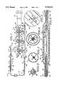
- FIG. 1is a side-elevational view of a multiple balloon catheter and a manifold for use with the same.
- FIG. 2is an enlarged cross-sectional view taken along the line 2--2 of FIG. 1.
- FIG. 3is an enlarged cross-sectional view taken along the line 3--3 of FIG. 1.
- FIG. 4is an enlarged cross-sectional view taken along the line 4--4 of FIG. 1.
- FIG. 5is an enlarged cross-sectional view taken along the line 5--5 of FIG. 1.
- FIG. 6is an enlarged partial view in section of the coaxial balloons shown in FIG. 1.
- FIG. 7is a side-elevational view of a multiple balloon stent delivery catheter and manifold for use with the same.
- FIG. 8is an enlarged cross-sectional view taken along the line 7--7 of FIG. 7.
- FIG. 9is a cross sectional view similar to that shown in FIG. 7 but showing the outer balloon inflated to place the stent.
- FIGS. 10, 11, 12, and 13are side-elevational views of additional embodiments of multiple balloon catheters incorporating the present invention.
- the multiple balloon catheteris for use in the vessel of a patient with an inflation/deflation device. It is comprised of a flexible elongate tubular member having proximal and distal extremities. A distal balloon is mounted on the distal extremity of the flexible elongate tubular member. Coaxial inner and outer balloons are mounted on the distal extremity of the flexible elongate member proximal of the distal balloon.
- the flexible elongate tubular memberhas balloon inflation lumens therein in communication with the interiors of the distal balloon and the inner and outer coaxial balloons.
- An inflation manifoldis secured to the proximal extremity of the flexible elongate tubular member and is in communication with the inflation lumens and is adapted to be connected to the inflation/deflation device.
- Valve meansis carried by the inflation/deflation manifold for inflating the distal balloon in the inner and outer coaxial balloons one at a time or in unison without removal of the inflation/deflation device.
- the multiple balloon catheter 11consists of a flexible elongate tubular member 12 having proximal and distal extremities 13 and 14 serving as a shaft for the multiple balloon catheter 11.
- the flexible elongate tubular member 12is formed of a suitable lubricous plastic such as Nylon or a copolymer of Nylon such as Pebax or other high lubricous materials such as polyethylene.
- Nylon 11has been found to be a particularly suitable material.
- Other Nylonssuch as Nylon 12 or Nylon 66 can be utilized.
- the diameter of the shaftcan be of a suitable size such as 3-French corresponding to 0.039" of the outside diameter.
- the shaft 12has a suitable length ranging from 130 to 175 centimeters and typically approximately 150 centimeters when used for angioplasty.
- the flexible elongate tubular member or shaft 12is typically an extrusion and is provided with a plurality of extruded lumens therein.
- the shaft 12is provided with a guide wire lumen 16 which is sized to receive a conventional guide wire 68, as for example one having a diameter of 0.014", and thus is provided with a diameter of 0.017".
- the shaftis also provided with three balloon inflation lumens, 17, 18 and 19 in which lumen 17 and 18 are generally crescent- shaped and lumen 19 is generally circular in cross section.
- a plurality of inflatable balloonsis provided on the distal extremity 14 of the flexible elongate tubular member 12.
- a distal balloon 21an inner balloon 22 which is proximal of the distal balloon 21, and an outer balloon 23 which is coaxial with the inner balloon 22.
- the balloons 21, 22 and 23are formed of a non-compliant or low-compliant high pressure material which is capable of withstanding pressures in the range of 18 to 20 atmospheres.
- Such high strength balloon materialstypically incorporate materials such as Nylon 12 or Nylon 11.
- the distal balloon 21can have a diameter ranging from 1.5 to 3 millimeters and typically approximately 2 millimeters.
- the inner balloon 22can have a diameter ranging from 2.0 to 4.0 millimeters and typically 2.5 or 3 millimeters, whereas the outer balloon 23 can have a diameter ranging from 2.5 to 5 millimeters and typically 3 millimeters to 3.5 millimeters.
- the balloonscan have a wall thickness ranging from 0.0005" to 0.0015" and preferably a thickness of approximately 0.00075".
- the balloons 21, 22 and 23can have a suitable working length, as for example the distal balloon 21 can have a working length of 20 millimeters, the inner balloon 22 a working length of 20 millimeters and the outer balloon 23 a working length of 22 millimeters. It should be appreciated that the balloons, if desired, can have increased or decreased lengths as desired.
- the balloons 21, 22 and 23are bonded in appropriate locations on the distal extremity 14 of the flexible elongate tubular member 12 in a suitable conventional manner as for example by the use of an adhesive, heat bonding or solvent bonding to form fluid tight seals so that the balloons can be inflated.
- an adhesive 26has been provided for securing the extremities of the balloons 21, 22 and 23 to the distal extremity 14 of the flexible elongate member 12.
- an adhesive 26is utilized for making these bonds.
- the flexible elongate extremity 14is also provided with holes of ports establishing communication with the balloon inflation lumens and the interior of the associated balloons.
- an opening or port 31establishing communication between the interior of the distal balloon 21 and lumen 19.
- an opening or port 32establishing communication between the lumen 17 and the interior of the inner balloon 22.
- a port 33establishes communication between the lumen 18 and the interior of the outer balloon 23.
- a soft atraumatic tip 36is provided on the distal extremity 14 and is secured thereto by suitable means such as adhesive (not shown). The tip can be formed of a soft plastic material as for example Pebax.
- Radiopaque markersare provided on the distal extremity 14 of the flexible elongate tubular member 12 to aid in locating the positions of the balloons 21, 22 and 23 during use and consist of a radiopaque marker 37 mounted on the flexible elongate tubular member 12 equidistant between the ends of the distal balloon 21.
- a pair of markers 38 and 39is also provided on the distal extremity of the flexible elongate tubular member 12 proximal of the marker 37 and spaced apart near the opposite ends of the inner balloon 22.
- the radiopaque markerscan be formed of a suitable radiopaque material such as gold or platinum.
- a manifold assembly 51is secured to the proximal extremity 13 of the flexible elongate tubular member 12 which can be utilized for inflating and deflating the balloons individually without having to disconnect and reconnect an inflation/deflation device 91.
- the manifold assembly 51consists of an elongate cylindrical body 52 formed of a suitable material such as polycarbonate plastic which is provided with a flat 53 so that the manifold assembly 51 will remain in an upright position when resting on a flat surface.
- the body 52is provided with a tapered or cone-shaped distal extremity 52a which has a bore 54 therein which has the proximal extremity 13 of the flexible elongate tubular member 12 sealed therein and bonded therein by suitable means such as an adhesive (not shown).
- a strain relief sleeve 56is provided on the proximal extremity 13.
- the manifold body 52is provided with spaced-apart balloon inflation chambers, namely a distal balloon chamber 57, an inner balloon chamber 58 and an outer balloon chamber 59.
- the inner balloon chamber 58is disposed proximally of the distal balloon chamber 57 and the outer balloon chamber 59 is disposed proximally of the inner balloon chamber 58.
- the body 52is provided with a plurality of longitudinally extending bores.
- a guide wire bore 61in alignment with the guide wire lumen 16 in the flexible elongate tubular member 12.
- balloon inflation bores 62, 63 and 64in communication with balloon inflation lumens 17, 18 and 19 respectively.
- the chambers 57, 58 and 59are in communication, respectively, with the bores 64, 63 and 62.
- a Luer fitting 66is mounted on the body 52 and is in communication with the guide wire bore 61 to provide a guide wire port which, as shown, has a guide wire 68 disposed therein.
- the guide wire 68is of a conventional type such as an 0.014" diameter guide wire.
- a Tuohy-Borst adaptertypically is carried by the Luer fitting 66 to prevent blood from seeping around the guide wire while the catheter 11 is in use.
- the manifold assembly 51includes means for supplying an inflation fluid to the chambers 57, 58 and 59 and consists of valve assemblies 71, 72 and 73 connected, respectively, to the chambers 57, 58 and 59.
- Each of the valve assemblies 71, 72 and 73consist of a cylindrical valve body 76 having a bore 77 therein and another bore 78 extending transversely therethrough.
- a stem 79is rotatably mounted in the bore 77 and has a bore 81 extending transversely therethrough and adapted to be moved into and out of registration with the bore 78 in the valve body 76.
- a handle 82is provided on the stem 79.
- Each valve body 76is connected to adjacent valve body 76.
- each valve body 76is provided with a male fitting 86 and a female fitting 87 in communication with the transverse bore 78 in the valve body 76.
- the male fitting 86 on one valve body 76mates with the female fitting 87 of the adjacent valve body 76 so that a fluid communication channel is established between the valve assemblies 71, 72 and 73.
- the most distal male fitting 86is truncated and is plugged with a plug 88.
- a Luer fitting 89is provided on the most proximal female fitting 87 and has mounted thereon a conventional ENDOFLATERTM or syringe 91.
- Each valve assembly 71, 72 and 73also includes a coupling 92 which couples the bore 77 into the respective chambers 57, 58 and 59.
- balloons 21, 22 and 23can be inflated and deflated individually or can be inflated simultaneously as desired merely by operation of the valve assemblies 71, 72 and 73 in an appropriate manner as hereinafter described.
- all of the valve assemblies 71, 72 and 73are turned to the closed position.
- the valve assembly 71is then rotated by 90° to turn it to an open position as shown in FIG. 1, after which an inflation/deflation device 91 is operated to introduce an inflation fluid chamber 57 and then into the bore 64 and into the lumen 19 for inflating the distal balloon 21.
- the balloon 21can also then be deflated.
- valve assembly 71can be turned another 90° to close it to prevent deflation of the balloon 21 or, alternatively, to deflate the balloon 21 and hold it uninflated, after which the catheter 11 can be moved as hereinafter described and the next balloon, as for example inner balloon 22 can be inflated by rotating the valve 72 to the open position. Thereafter in a similar manner, the outer balloon 73 can be inflated.
- FIG. 7Also incorporating the present invention is a multiple balloon stent delivery catheter 101 which is shown in FIG. 7.
- This multiple balloon stent delivery catheter 101is very similar to the multiple balloon catheter 11 hereinbefore described. It consists of a flexible elongate tubular member 12 having proximal and distal extremities 13 and 14 with a distal balloon 21 and inner and outer balloons 22 and 23.
- a balloon expandable stent 102is frictionally mounted on the coaxial inner and outer balloons 22 and 23. As shown in FIG. 8, the balloons 22 and 23 are not inflated and the balloon expandable stent 102 is frictionally secured to the outer balloon 23 sufficiently tightly so that a force in excess of approximately one-half pound is required to remove the stent 102 from the outer balloon 23.
- the balloon stent 102can be of any conventional type and can be formed of a suitable material such as stainless steel or a nickel titanium alloy. A stent of desired length can be provided. Also if desired, stents can be provided in tandem on the outer balloon 23.
- the stent 102is positioned relative to the radiopaque markers 38 and 39 so that the positioning of the stent can be precisely ascertained during deployment as hereinafter described.
- Meansis provided for covering the stent 102 until it has been deployed and consists of a sheath 106 and can be formed of a very thin molded plastic having a lubricous outer surface such as one made of Teflon.
- the sheath 106can have a single wall thickness ranging from 0.001" to 0.005" and preferably a wall thickness of approximately 0.0015".
- the sheath 106should have a wall thickness which will resist elongation while being withdrawn as hereinafter described.
- the sheath 106has a distal extremity 107 which extends slightly beyond the distal extremity of the balloon expandable stent 102, as for example a distance of approximately 1 millimeter.
- the sheath 106then extends proximally over the flexible elongate tubular member shaft 12 to the proximal extremity 13 thereof.
- the proximal extremity 108 of the sheath 106is secured to a cylindrical fitting 111 forming a part of a hemostasis valve assembly 112.
- the hemostasis valve assembly 112includes an internally threaded cap 116 which is threadedly mounted on the cylindrical fitting 111 and engages an O-ring 117 to form a liquid-tight seal between the fitting 111 and the proximal extremity 13 of the flexible elongate member 12.
- a Luer-type fitting 121 in the form of a side armis secured to the fitting 111 and provides a port 122 for introducing a flushing saline liquid which can pass into the annular space 123 between the exterior of the flexible elongate tubular member or shaft 12 over the outer balloon 23 within the sheath 106 and exiting out the distal extremity 107 of the sheath 106 to be utilized for a purpose hereinafter described.
- a marker 126 visible to the human eye formed of a suitable material such as a paint or a colored tapeis provided on the proximal extremity 13 of the flexible elongate tubular member 12 proximal of the hemostasis valve assembly 112.
- the spacing between the proximal extremity of the hemostasis valve assembly 112 and the marker 126should be a distance at least equal to or slightly greater than the length of the stent 102 so that when the threaded cap 116 is loosened, the fitting 111 can be retracted to pull with it the sheath 106.
- the threaded cap 116is adjacent to or overlies the marker 126, the sheath 106 will have cleared the stent 102 to permit placement of the stent 102 as hereinafter described.
- a manifold assembly 51is provided which is substantially identical to the manifold assembly 51 hereinbefore described.
- the distal balloon 21can be inflated by rotating the valve 71 to an open position and then introducing a suitable inflation medium such as a contrast medium to inflate the balloon to its maximum diameter and to cause a flow passage of increased size to be created in the stenosis. After this has been accomplished, the distal balloon 21 is deflated by removing the inflation medium using the inflation/deflation device or syringe 91.
- a suitable inflation mediumsuch as a contrast medium
- the distal extremity 14 of the flexible elongate tubular member 12is then further advanced into the stenosis until the coaxial inner and outer balloons 22 and 23 are positioned within the stenosis. This again can be visualized by observing the positioning of the markers 38 and 39 under fluoroscopy.
- the valve assembly 71is then turned to a closed position and the valve assembly 72 is turned to an open position and an inflation medium is introduced into the inner balloon 22 which moves the outer uninflated balloon 23 into engagement with the stenosis to cause a larger size opening to be formed in the stenosis.
- the valve 73can be turned to an open position and the outer balloon 23 can be inflated with a contrast medium or other suitable fluid. After a suitable dilation of the stenosis has occurred, the outer and inner balloons 23 and 22 can be deflated by withdrawing the inflation medium.
- the multiple balloon catheter 11 and the guide wire 68can be removed from the femoral artery and the femoral artery closed surgically in a conventional manner. From the foregoing, it can be seen that all three of the balloons 21, 22 and 23 can be inflated individually or, alternatively, can be inflated in unison if desired without removal of the inflation/deflation device 91. This is made possible by use of the manifold assembly 51.
- the multiple balloon stent delivery catheter 101is advanced over the guide wire 68 until the small distal balloon 21 has been advanced into registration with the stenosis by observation of the marker 37.
- the valve 71is opened and an inflation medium is introduced through the manifold 51 with the valves 72 and 73 in closed positions to inflate the distal balloon 21 to increase the size of the flow passage through the stenosis.
- the distal balloon 21is deflated.
- the distal extremity 14 of the multiple balloon stent delivery catheter 101is advanced until the coaxial inner and outer balloons 22 and 23 are disposed within the stenosis by observation of the spaced apart markers 38 and 39. When this has occurred, the stent 102 is also positioned within the stenosis as well as the distal extremity 107 of the sheath 106.
- the position of the stent 102is again verified. If it is desired to change the position of the stent 102, the distal extremity 14 of the multiple balloon stent delivery catheter 101 can be changed after which the distal balloon 21 can be again inflated in the vessel to serve as an anchor for the distal extremity 14 of the flexible elongate tubular member 12. Thereafter, the sheath 106 can be removed from over the stent 102 by retracting proximally the hemostatic valve assembly 112 after loosening the threaded cap 116 and pulling it proximally until the cap 116 is in registration with the marker 126 to assure that the sheath has cleared the stent 102.
- the inner balloon 22can be inflated by opening the valve assembly 72 and leaving the valve assembly 73 closed and supplying an inflation medium to the inner balloon 22 to expand the stent 102 radially and outwardly to increase the size of the opening or flow passage through the stenosis.
- the outer balloon 23can then be inflated by opening of the valve 73 and supplying additional inflation medium to the manifold assembly 51 to inflate the outer balloon 23 and to carry with it and expand the stent 102 to further increase the size of the opening through the stenosis.
- the balloons 21, 22 and 23can be deflated by withdrawing inflation medium from the same.
- the entire multiple balloon stent delivery catheter 101 along with the guide wire 68can then be removed from the femoral artery and the femoral artery closed surgically in a conventional manner.
- the distal balloon 21can have any appropriate size.
- itcan be a small size balloon as hereinbefore described or, if desired, it can be a larger size balloon substantially the same size as the outer balloon 23.
- a plurality of distal balloonscan be provided which are disposed in tandem, as for example as shown in FIG. 11 in which another distal balloon 21a proximal of the other distal balloon 21 has been provided in the multiple balloon catheter 136.
- An additional marker 37ahas been provided in the balloon 21a.
- FIG. 12Another multiple balloon catheter 141 incorporating the present invention is shown in FIG. 12 in which a stepped outer coaxial balloon 23a is provided having a distal extremity of lesser diameter than the proximal extremity of the balloon 23a.
- the proximal and distal portions of the balloon 23acan be of various lengths as desired.
- the balloons provided on the multiple balloon catheters 11 and 101can have various configurations.
- the outer balloon 23bcan be in the form of a tapered balloon having a taper which gradually decreases in a distal direction.
- the balloon catheters 11 and 101are high pressure substantially non-distensible balloons which can be distended at highly controlled and predictable rates.
- the balloonscan be of various sizes ranging from 1 to 8 millimeters in diameter and 10 to 40 millimeters in length.
- the balloonscan have various profiles, as for example straight, tapered, center or ends bulging portions.
- the catheterscan be formed for over-the-wire use or can be provided with a fixed guide wire.
- the distal ballooncan be utilized for maintaining an anatomical position for the catheter while other functions are being performed with the catheter, as for example deployment of a stent as hereinbefore described.
- the multiple balloon cathetercan be utilized for delivering a stent without having a sheath covering the stent when that is desired as for example for purposes of economy.
- the method of the present inventioncan be utilized with a multiple balloon stent delivery catheter which has an outer coaxial balloon which is a stepped balloon having proximal and distal portions with the distal portion having a diameter less than the diameter of the proximal portion.
- the stentcan be mounted on the distal portion of smaller diameter. When this is the case, the sheath can be withdrawn to uncover the stent while still covering the proximal portion of the outer coaxial balloon.
- the outer coaxial ballooncan be inflated to cause expansion of the uncovered distal portion to cause deployment of the stent.
- the stentcan be mounted on the proximal portion of larger diameter and covered by the sheath.
- the distal portion of smaller diametercan then be advanced into the stenosis and can be utilized for predilating the stenosis.
- the outer coaxial ballooncan then be delated and the catheter advanced so that the proximal portion of larger diameter with the stent thereon can be moved into the stenosis through the larger flow passage formed in inflation of the distal portion.
- the sheathcan be withdrawn and the proximal portion of the distal balloon can be inflated to deploy the stent.
- the methodcan be utilized in a similar manner with the tapered outer coaxial balloon with the stent being carried by the tapered outer balloon and being advanced into the stenosis.
- the sheathcan be withdrawn to uncover the stent after which the balloon can be inflated to deploy the stent.
- stent delivery catheter of the present inventionhas been described for delivering a single stent at a time, it should be appreciated that a plurality of shorter segmented stents all mounted on a balloon and, if necessary, on a longer balloon and then deployed as hereinbefore described to treat longer lesions or a plurality of lesions in a vessel.
- the present multiple balloon catheterhas been described principally as a stent delivery catheter, it should be appreciated that it also can be utilized for dilating one or more stenoses in a vessel. This can be readily accomplished by deploying the catheter into the vessel as hereinbefore described and then advancing the distal balloon into a stenosis and dilating that stenosis to increase the size of the flow passage therethrough. The distal balloon can be then deflated and the catheter advanced to advance the coaxial outer and inner balloons into registration with the stenosis after which at least one of the inner and outer balloons can be inflated to increase the size of the flow passage in the stenosis.
- the inner coaxial ballooncan be inflated followed by inflation of the outer coaxial balloon when a larger size flow passage is desired through the stenosis. It should be appreciated that if there are additional stenoses in the same vessel, the multiple balloons can be further advanced into the vessel to perform the same dilating procedure with additional stenoses in the vessel.
- catheters 11 and 101have been described principally in connection with angioplasty procedures involving stenoses in vessels of the heart, it should be appreciated that the teaching herein is equally applicable to procedures in carotid arteries and other vessels in the human body.
Landscapes
- Health & Medical Sciences (AREA)
- Engineering & Computer Science (AREA)
- Heart & Thoracic Surgery (AREA)
- Life Sciences & Earth Sciences (AREA)
- Biomedical Technology (AREA)
- Public Health (AREA)
- Animal Behavior & Ethology (AREA)
- Veterinary Medicine (AREA)
- General Health & Medical Sciences (AREA)
- Child & Adolescent Psychology (AREA)
- Hematology (AREA)
- Biophysics (AREA)
- Pulmonology (AREA)
- Anesthesiology (AREA)
- Cardiology (AREA)
- Oral & Maxillofacial Surgery (AREA)
- Transplantation (AREA)
- Vascular Medicine (AREA)
- Media Introduction/Drainage Providing Device (AREA)
Abstract
Description
Claims (13)
Priority Applications (6)
| Application Number | Priority Date | Filing Date | Title |
|---|---|---|---|
| US08/717,299US5725535A (en) | 1996-09-20 | 1996-09-20 | Multiple balloon stent delivery catheter and method |
| AU44163/97AAU4416397A (en) | 1996-09-20 | 1997-09-15 | Multiple balloon stent delivery catheter and method |
| EP97942475AEP0942766A4 (en) | 1996-09-20 | 1997-09-15 | Multiple balloon stent delivery catheter and method |
| PCT/US1997/016326WO1998011935A1 (en) | 1996-09-20 | 1997-09-15 | Multiple balloon stent delivery catheter and method |
| JP10514803AJP2001500761A (en) | 1996-09-20 | 1997-09-15 | Multiple balloon stent delivery catheter and method |
| US08/949,726US5788708A (en) | 1996-09-20 | 1997-10-14 | Multiple balloon stent delivery catheter and method |
Applications Claiming Priority (1)
| Application Number | Priority Date | Filing Date | Title |
|---|---|---|---|
| US08/717,299US5725535A (en) | 1996-09-20 | 1996-09-20 | Multiple balloon stent delivery catheter and method |
Related Child Applications (1)
| Application Number | Title | Priority Date | Filing Date |
|---|---|---|---|
| US08/949,726DivisionUS5788708A (en) | 1996-09-20 | 1997-10-14 | Multiple balloon stent delivery catheter and method |
Publications (1)
| Publication Number | Publication Date |
|---|---|
| US5725535Atrue US5725535A (en) | 1998-03-10 |
Family
ID=24881469
Family Applications (2)
| Application Number | Title | Priority Date | Filing Date |
|---|---|---|---|
| US08/717,299Expired - Fee RelatedUS5725535A (en) | 1996-09-20 | 1996-09-20 | Multiple balloon stent delivery catheter and method |
| US08/949,726Expired - Fee RelatedUS5788708A (en) | 1996-09-20 | 1997-10-14 | Multiple balloon stent delivery catheter and method |
Family Applications After (1)
| Application Number | Title | Priority Date | Filing Date |
|---|---|---|---|
| US08/949,726Expired - Fee RelatedUS5788708A (en) | 1996-09-20 | 1997-10-14 | Multiple balloon stent delivery catheter and method |
Country Status (5)
| Country | Link |
|---|---|
| US (2) | US5725535A (en) |
| EP (1) | EP0942766A4 (en) |
| JP (1) | JP2001500761A (en) |
| AU (1) | AU4416397A (en) |
| WO (1) | WO1998011935A1 (en) |
Cited By (42)
| Publication number | Priority date | Publication date | Assignee | Title |
|---|---|---|---|---|
| WO1999056809A3 (en)* | 1998-05-01 | 2000-01-06 | Intella Interventional Corp | Dual cathether assembly |
| WO2000003662A1 (en)* | 1998-07-14 | 2000-01-27 | Advanced Cardiovascular Systems, Inc. | Stent delivery device and method of use |
| US6083205A (en)* | 1998-01-28 | 2000-07-04 | Intella Interventional Systems | Multiple valve single port manifold |
| US6093463A (en)* | 1997-12-12 | 2000-07-25 | Intella Interventional Systems, Inc. | Medical devices made from improved polymer blends |
| US6156053A (en)* | 1998-05-01 | 2000-12-05 | Intella Interventional Systems, Inc. | Dual catheter assembly |
| US6174327B1 (en) | 1998-02-27 | 2001-01-16 | Scimed Life Systems, Inc. | Stent deployment apparatus and method |
| US6210318B1 (en) | 1999-03-09 | 2001-04-03 | Abiomed, Inc. | Stented balloon pump system and method for using same |
| WO2001078627A1 (en) | 2000-04-12 | 2001-10-25 | Scimed Life Systems, Inc. | Stent delivery catheter with retractable balloon |
| US6379329B1 (en)* | 1999-06-02 | 2002-04-30 | Cordis Neurovascular, Inc. | Detachable balloon embolization device and method |
| US6482172B1 (en)* | 2000-02-09 | 2002-11-19 | Jeffrey J. Thramann | Flow-by channel catheter and method of use |
| US6508782B1 (en)* | 1992-05-19 | 2003-01-21 | Bacchus Vascular, Inc. | Thrombolysis device |
| US6527739B1 (en) | 2000-12-29 | 2003-03-04 | Advanced Cardiovascular Systems, Inc. | Spiraled balloon arrangement for treatment of a tortuous vessel |
| US6602226B1 (en) | 2000-10-12 | 2003-08-05 | Scimed Life Systems, Inc. | Low-profile stent delivery system and apparatus |
| US6679860B2 (en) | 2001-06-19 | 2004-01-20 | Medtronic Ave, Inc. | Intraluminal therapy catheter with inflatable helical member and methods of use |
| US20050004647A1 (en)* | 2003-07-03 | 2005-01-06 | William Cook Europe Aps | Hybrid stent apparatus |
| US6884257B1 (en) | 2000-11-28 | 2005-04-26 | Advanced Cardiovascular Systems, Inc. | Stent delivery system with adjustable length balloon |
| US6936025B1 (en) | 1992-05-19 | 2005-08-30 | Bacchus Vascular, Inc. | Thrombolysis device |
| US20050251193A1 (en)* | 2003-08-29 | 2005-11-10 | Lary G B | Combination catheter and stent system |
| US20060265041A1 (en)* | 2005-05-23 | 2006-11-23 | Arashmidos Sanati | Apparatus and methods for delivering a stent into an ostium |
| US20070038283A1 (en)* | 2004-02-06 | 2007-02-15 | Mustapha Jihad A | Ostial stent and balloon |
| US20070073388A1 (en)* | 2005-08-22 | 2007-03-29 | Krolik Jeffrey A | Flared stents and apparatus and methods for delivering them |
| US20070129749A1 (en)* | 2005-12-07 | 2007-06-07 | Boston Scientific Scimed, Inc. | Tapered multi-chamber balloon |
| US20080071305A1 (en)* | 2003-03-17 | 2008-03-20 | Delegge Rebecca | Intragastric catheter |
| US20090143728A1 (en)* | 2007-11-30 | 2009-06-04 | Numed, Inc. | Balloon catheter with safety feature |
| US8118856B2 (en) | 2009-07-27 | 2012-02-21 | Endologix, Inc. | Stent graft |
| US20120277811A1 (en)* | 2011-04-29 | 2012-11-01 | Kyphon Sarl | Bone tamp and methods of use |
| US9034025B2 (en) | 2005-05-23 | 2015-05-19 | Ostial Corporation | Balloon catheters and methods for use |
| US9387102B2 (en) | 2014-03-27 | 2016-07-12 | Clever Cath Technologies, LLC | Sheathless predilatation angioplasty and stent deployment catheter |
| US9393100B2 (en) | 2010-11-17 | 2016-07-19 | Endologix, Inc. | Devices and methods to treat vascular dissections |
| WO2017009356A1 (en)* | 2015-07-13 | 2017-01-19 | Jotec Gmbh | Balloon catheter |
| US9579103B2 (en) | 2009-05-01 | 2017-02-28 | Endologix, Inc. | Percutaneous method and device to treat dissections |
| CN106539607A (en)* | 2017-01-12 | 2017-03-29 | 张潘 | A kind of Interventional Hemostasis device |
| US9668899B2 (en) | 2014-03-27 | 2017-06-06 | Clever Cath Technologies, LLC | Rapid exchange sheathless predilatation angioplasty and stent deployment catheter |
| WO2017142579A1 (en)* | 2016-02-17 | 2017-08-24 | Clever Cath Technologies Llc | Rapid exchange sheathless predilatation angioplasty and stent deployment catheter |
| US9895517B2 (en) | 2011-01-18 | 2018-02-20 | Loma Vista Medical, Inc. | Inflatable medical devices |
| US10350395B2 (en) | 2017-06-23 | 2019-07-16 | Cook Medical Technologies Llc | Introducer for lumen support or dilation |
| US10434291B2 (en) | 2016-11-28 | 2019-10-08 | Cook Medical Technologies Llc | Curved passageway conforming balloon catheter with nested balloons |
| WO2020072837A1 (en) | 2018-10-03 | 2020-04-09 | Ostial Corporation | Inflation devices and systems for balloon catheters and methods for use |
| US10772717B2 (en) | 2009-05-01 | 2020-09-15 | Endologix, Inc. | Percutaneous method and device to treat dissections |
| US10799348B2 (en) | 2012-10-18 | 2020-10-13 | Loma Vista Medical, Inc. | Reinforced inflatable medical devices |
| WO2021242531A1 (en)* | 2020-05-29 | 2021-12-02 | Basis Medical, Llc | Multi-lumen manifold and method of operating a multi-lumen manifold |
| CN116250966A (en)* | 2022-12-02 | 2023-06-13 | 杭州心畅医疗器械有限公司 | A valve delivery system |
Families Citing this family (26)
| Publication number | Priority date | Publication date | Assignee | Title |
|---|---|---|---|---|
| US6575966B2 (en)* | 1999-08-23 | 2003-06-10 | Cryocath Technologies Inc. | Endovascular cryotreatment catheter |
| US6471672B1 (en) | 1999-11-10 | 2002-10-29 | Scimed Life Systems | Selective high pressure dilation balloon |
| US8308797B2 (en) | 2002-01-04 | 2012-11-13 | Colibri Heart Valve, LLC | Percutaneously implantable replacement heart valve device and method of making same |
| US20030153905A1 (en)* | 2002-01-25 | 2003-08-14 | Edwards Stuart Denzil | Selective ablation system |
| US6761734B2 (en) | 2002-07-22 | 2004-07-13 | William S. Suhr | Segmented balloon catheter for stenting bifurcation lesions |
| US7972372B2 (en) | 2003-04-14 | 2011-07-05 | Tryton Medical, Inc. | Kit for treating vascular bifurcations |
| US7481834B2 (en) | 2003-04-14 | 2009-01-27 | Tryton Medical, Inc. | Stent for placement at luminal os |
| US7758630B2 (en) | 2003-04-14 | 2010-07-20 | Tryton Medical, Inc. | Helical ostium support for treating vascular bifurcations |
| US8083791B2 (en) | 2003-04-14 | 2011-12-27 | Tryton Medical, Inc. | Method of treating a lumenal bifurcation |
| US7717953B2 (en) | 2004-10-13 | 2010-05-18 | Tryton Medical, Inc. | Delivery system for placement of prosthesis at luminal OS |
| US7731747B2 (en) | 2003-04-14 | 2010-06-08 | Tryton Medical, Inc. | Vascular bifurcation prosthesis with multiple thin fronds |
| US8109987B2 (en) | 2003-04-14 | 2012-02-07 | Tryton Medical, Inc. | Method of treating a lumenal bifurcation |
| US7261730B2 (en)* | 2003-11-14 | 2007-08-28 | Lumerx, Inc. | Phototherapy device and system |
| US9440054B2 (en)* | 2008-05-14 | 2016-09-13 | Onset Medical Corporation | Expandable transapical sheath and method of use |
| US8382818B2 (en) | 2009-07-02 | 2013-02-26 | Tryton Medical, Inc. | Ostium support for treating vascular bifurcations |
| JP2011152181A (en)* | 2010-01-26 | 2011-08-11 | Toray Ind Inc | Balloon catheter |
| KR101022487B1 (en)* | 2010-05-27 | 2011-03-15 | 변기현 | Catheter with integrated pre-expanded and stent balloons |
| JP5936610B2 (en)* | 2010-06-28 | 2016-06-22 | コリブリ ハート バルブ エルエルシーColibri Heart Valve Llc | Device for intracavity delivery of an intravascular injection device |
| EP2642946B1 (en) | 2010-11-24 | 2023-08-16 | Poseidon Medical Inc. | Support for treating vascular bifurcations |
| AU2011343755A1 (en) | 2010-12-14 | 2013-06-06 | Colibri Heart Valve Llc | Percutaneously deliverable heart valve including folded membrane cusps with integral leaflets |
| US10500077B2 (en) | 2012-04-26 | 2019-12-10 | Poseidon Medical Inc. | Support for treating vascular bifurcations |
| US10702678B2 (en)* | 2013-10-14 | 2020-07-07 | Gerstner Medical, Llc | Multiple balloon venous occlusion catheter |
| CN106491252B (en)* | 2016-11-25 | 2018-03-27 | 徐泽升 | Coronary ostium support Precise Position System |
| JP2019058284A (en)* | 2017-09-25 | 2019-04-18 | テルモ株式会社 | Treatment method |
| EP3693739A1 (en) | 2019-02-06 | 2020-08-12 | Stefan Schreier | Method and device for isolating desired cells from a sample of nonmagnetic biological material |
| DE202021105458U1 (en) | 2021-10-08 | 2023-01-24 | Sanolibio Co., Ltd. | Device for the magnetic purification of biological samples |
Citations (3)
| Publication number | Priority date | Publication date | Assignee | Title |
|---|---|---|---|---|
| US5226889A (en)* | 1990-07-30 | 1993-07-13 | Imad Sheiban | Double balloon catheter for stent implantation |
| US5456694A (en)* | 1994-05-13 | 1995-10-10 | Stentco, Inc. | Device for delivering and deploying intraluminal devices |
| US5632760A (en)* | 1994-10-20 | 1997-05-27 | Cordis Corporation | Balloon catheter for stent implantation |
Family Cites Families (12)
| Publication number | Priority date | Publication date | Assignee | Title |
|---|---|---|---|---|
| US4423725A (en)* | 1982-03-31 | 1984-01-03 | Baran Ostap E | Multiple surgical cuff |
| US4921483A (en)* | 1985-12-19 | 1990-05-01 | Leocor, Inc. | Angioplasty catheter |
| US4744366A (en)* | 1986-09-10 | 1988-05-17 | Jang G David | Concentric independently inflatable/deflatable multiple diameter balloon angioplasty catheter systems and method of use |
| JPS6377461A (en)* | 1986-09-19 | 1988-04-07 | 住友ベークライト株式会社 | Medical balloon catheter |
| US4753238A (en)* | 1987-01-06 | 1988-06-28 | Advanced Cardiovascular Systems, Inc. | Proximal manifold and adapter |
| JPS6486983A (en)* | 1987-09-30 | 1989-03-31 | Nippon Zeon Co | Bodily organ dilator |
| JP3101299B2 (en)* | 1990-05-24 | 2000-10-23 | テルモ株式会社 | Intra-aortic balloon catheter |
| JP3134365B2 (en)* | 1991-06-27 | 2001-02-13 | 日本ゼオン株式会社 | Balloon catheter |
| US5447497A (en)* | 1992-08-06 | 1995-09-05 | Scimed Life Systems, Inc | Balloon catheter having nonlinear compliance curve and method of using |
| US5360401A (en)* | 1993-02-18 | 1994-11-01 | Advanced Cardiovascular Systems, Inc. | Catheter for stent delivery |
| US5571135A (en)* | 1993-10-22 | 1996-11-05 | Scimed Life Systems Inc. | Stent delivery apparatus and method |
| NL9500284A (en)* | 1994-10-20 | 1996-06-03 | Cordis Europ | Catheter for stent implantation. |
- 1996
- 1996-09-20USUS08/717,299patent/US5725535A/ennot_activeExpired - Fee Related
- 1997
- 1997-09-15JPJP10514803Apatent/JP2001500761A/enactivePending
- 1997-09-15EPEP97942475Apatent/EP0942766A4/ennot_activeWithdrawn
- 1997-09-15AUAU44163/97Apatent/AU4416397A/ennot_activeAbandoned
- 1997-09-15WOPCT/US1997/016326patent/WO1998011935A1/ennot_activeApplication Discontinuation
- 1997-10-14USUS08/949,726patent/US5788708A/ennot_activeExpired - Fee Related
Patent Citations (3)
| Publication number | Priority date | Publication date | Assignee | Title |
|---|---|---|---|---|
| US5226889A (en)* | 1990-07-30 | 1993-07-13 | Imad Sheiban | Double balloon catheter for stent implantation |
| US5456694A (en)* | 1994-05-13 | 1995-10-10 | Stentco, Inc. | Device for delivering and deploying intraluminal devices |
| US5632760A (en)* | 1994-10-20 | 1997-05-27 | Cordis Corporation | Balloon catheter for stent implantation |
Cited By (67)
| Publication number | Priority date | Publication date | Assignee | Title |
|---|---|---|---|---|
| US6936025B1 (en) | 1992-05-19 | 2005-08-30 | Bacchus Vascular, Inc. | Thrombolysis device |
| US6508782B1 (en)* | 1992-05-19 | 2003-01-21 | Bacchus Vascular, Inc. | Thrombolysis device |
| US6093463A (en)* | 1997-12-12 | 2000-07-25 | Intella Interventional Systems, Inc. | Medical devices made from improved polymer blends |
| US6083205A (en)* | 1998-01-28 | 2000-07-04 | Intella Interventional Systems | Multiple valve single port manifold |
| US6174327B1 (en) | 1998-02-27 | 2001-01-16 | Scimed Life Systems, Inc. | Stent deployment apparatus and method |
| US6156053A (en)* | 1998-05-01 | 2000-12-05 | Intella Interventional Systems, Inc. | Dual catheter assembly |
| WO1999056809A3 (en)* | 1998-05-01 | 2000-01-06 | Intella Interventional Corp | Dual cathether assembly |
| US6136011A (en)* | 1998-07-14 | 2000-10-24 | Advanced Cardiovascular Systems, Inc. | Stent delivery system and method of use |
| WO2000003662A1 (en)* | 1998-07-14 | 2000-01-27 | Advanced Cardiovascular Systems, Inc. | Stent delivery device and method of use |
| US6210318B1 (en) | 1999-03-09 | 2001-04-03 | Abiomed, Inc. | Stented balloon pump system and method for using same |
| US6379329B1 (en)* | 1999-06-02 | 2002-04-30 | Cordis Neurovascular, Inc. | Detachable balloon embolization device and method |
| US6482172B1 (en)* | 2000-02-09 | 2002-11-19 | Jeffrey J. Thramann | Flow-by channel catheter and method of use |
| US6689097B2 (en) | 2000-02-09 | 2004-02-10 | Jeffrey J. Thramann | Flow-by channel catheter and method of use |
| WO2001078627A1 (en) | 2000-04-12 | 2001-10-25 | Scimed Life Systems, Inc. | Stent delivery catheter with retractable balloon |
| US6702843B1 (en) | 2000-04-12 | 2004-03-09 | Scimed Life Systems, Inc. | Stent delivery means with balloon retraction means |
| US6602226B1 (en) | 2000-10-12 | 2003-08-05 | Scimed Life Systems, Inc. | Low-profile stent delivery system and apparatus |
| US6884257B1 (en) | 2000-11-28 | 2005-04-26 | Advanced Cardiovascular Systems, Inc. | Stent delivery system with adjustable length balloon |
| US6527739B1 (en) | 2000-12-29 | 2003-03-04 | Advanced Cardiovascular Systems, Inc. | Spiraled balloon arrangement for treatment of a tortuous vessel |
| US6679860B2 (en) | 2001-06-19 | 2004-01-20 | Medtronic Ave, Inc. | Intraluminal therapy catheter with inflatable helical member and methods of use |
| US20080071305A1 (en)* | 2003-03-17 | 2008-03-20 | Delegge Rebecca | Intragastric catheter |
| US7883525B2 (en)* | 2003-03-17 | 2011-02-08 | Delegge Rebecca | Intragastric catheter |
| US20050004647A1 (en)* | 2003-07-03 | 2005-01-06 | William Cook Europe Aps | Hybrid stent apparatus |
| US20050251193A1 (en)* | 2003-08-29 | 2005-11-10 | Lary G B | Combination catheter and stent system |
| US20070038283A1 (en)* | 2004-02-06 | 2007-02-15 | Mustapha Jihad A | Ostial stent and balloon |
| US20060265041A1 (en)* | 2005-05-23 | 2006-11-23 | Arashmidos Sanati | Apparatus and methods for delivering a stent into an ostium |
| US9034025B2 (en) | 2005-05-23 | 2015-05-19 | Ostial Corporation | Balloon catheters and methods for use |
| US20120004717A1 (en)* | 2005-05-23 | 2012-01-05 | Incept Llc | Apparatus and methods for delivering a stent into an ostium |
| US7862601B2 (en)* | 2005-05-23 | 2011-01-04 | Incept Llc | Apparatus and methods for delivering a stent into an ostium |
| US20070073388A1 (en)* | 2005-08-22 | 2007-03-29 | Krolik Jeffrey A | Flared stents and apparatus and methods for delivering them |
| US10092429B2 (en) | 2005-08-22 | 2018-10-09 | Incept, Llc | Flared stents and apparatus and methods for delivering them |
| US8142395B2 (en)* | 2005-12-07 | 2012-03-27 | Boston Scientific Scimed, Inc. | Tapered multi-chamber balloon |
| US7766893B2 (en)* | 2005-12-07 | 2010-08-03 | Boston Scientific Scimed, Inc. | Tapered multi-chamber balloon |
| US20070129749A1 (en)* | 2005-12-07 | 2007-06-07 | Boston Scientific Scimed, Inc. | Tapered multi-chamber balloon |
| US20100298860A1 (en)* | 2005-12-07 | 2010-11-25 | Boston Scientific Scimed, Inc. | Tapered multi-chamber balloon |
| US20090143728A1 (en)* | 2007-11-30 | 2009-06-04 | Numed, Inc. | Balloon catheter with safety feature |
| US10772717B2 (en) | 2009-05-01 | 2020-09-15 | Endologix, Inc. | Percutaneous method and device to treat dissections |
| US9579103B2 (en) | 2009-05-01 | 2017-02-28 | Endologix, Inc. | Percutaneous method and device to treat dissections |
| US8118856B2 (en) | 2009-07-27 | 2012-02-21 | Endologix, Inc. | Stent graft |
| US10874502B2 (en) | 2009-07-27 | 2020-12-29 | Endologix Llc | Stent graft |
| US9907642B2 (en) | 2009-07-27 | 2018-03-06 | Endologix, Inc. | Stent graft |
| US8821564B2 (en) | 2009-07-27 | 2014-09-02 | Endologix, Inc. | Stent graft |
| US9393100B2 (en) | 2010-11-17 | 2016-07-19 | Endologix, Inc. | Devices and methods to treat vascular dissections |
| US9895517B2 (en) | 2011-01-18 | 2018-02-20 | Loma Vista Medical, Inc. | Inflatable medical devices |
| US9107699B2 (en)* | 2011-04-29 | 2015-08-18 | Kyphon Sarl | Bone tamp and methods of use |
| US20120277811A1 (en)* | 2011-04-29 | 2012-11-01 | Kyphon Sarl | Bone tamp and methods of use |
| CN103987332B (en)* | 2011-04-29 | 2017-05-10 | 凯丰有限责任公司 | Bone Tampers and Methods of Use |
| US8728081B2 (en)* | 2011-04-29 | 2014-05-20 | Warsaw Orthopedic, Inc. | Bone tamp and methods of use |
| US20140107716A1 (en)* | 2011-04-29 | 2014-04-17 | Kyphon Sarl | Bone tamp and methods of use |
| CN103987332A (en)* | 2011-04-29 | 2014-08-13 | 凯丰有限责任公司 | Bone Tampers and Methods of Use |
| US10799348B2 (en) | 2012-10-18 | 2020-10-13 | Loma Vista Medical, Inc. | Reinforced inflatable medical devices |
| US9668899B2 (en) | 2014-03-27 | 2017-06-06 | Clever Cath Technologies, LLC | Rapid exchange sheathless predilatation angioplasty and stent deployment catheter |
| US9387102B2 (en) | 2014-03-27 | 2016-07-12 | Clever Cath Technologies, LLC | Sheathless predilatation angioplasty and stent deployment catheter |
| US10898359B2 (en) | 2015-07-13 | 2021-01-26 | Jotec Gmbh | Balloon catheter |
| WO2017009356A1 (en)* | 2015-07-13 | 2017-01-19 | Jotec Gmbh | Balloon catheter |
| WO2017142579A1 (en)* | 2016-02-17 | 2017-08-24 | Clever Cath Technologies Llc | Rapid exchange sheathless predilatation angioplasty and stent deployment catheter |
| US10434291B2 (en) | 2016-11-28 | 2019-10-08 | Cook Medical Technologies Llc | Curved passageway conforming balloon catheter with nested balloons |
| CN106539607A (en)* | 2017-01-12 | 2017-03-29 | 张潘 | A kind of Interventional Hemostasis device |
| US10350395B2 (en) | 2017-06-23 | 2019-07-16 | Cook Medical Technologies Llc | Introducer for lumen support or dilation |
| US20200108234A1 (en)* | 2018-10-03 | 2020-04-09 | Ostial Corporation | Inflation devices and systems for balloon catheters and methods for use |
| WO2020072837A1 (en) | 2018-10-03 | 2020-04-09 | Ostial Corporation | Inflation devices and systems for balloon catheters and methods for use |
| CN113301942A (en)* | 2018-10-03 | 2021-08-24 | 奥斯蒂尔公司 | Inflation device and system for balloon catheter and method of use thereof |
| EP3860701A4 (en)* | 2018-10-03 | 2022-06-22 | Ostial Corporation | BALLOON CATHETER INFLATORS AND SYSTEMS AND METHODS OF USE |
| US11850386B2 (en)* | 2018-10-03 | 2023-12-26 | Ostial Corporation | Inflation devices and systems for balloon catheters and methods for use |
| US20240277979A1 (en)* | 2018-10-03 | 2024-08-22 | Ostial Corporation | Inflation devices and systems for balloon catheters and methods for use |
| WO2021242531A1 (en)* | 2020-05-29 | 2021-12-02 | Basis Medical, Llc | Multi-lumen manifold and method of operating a multi-lumen manifold |
| US11666744B2 (en) | 2020-05-29 | 2023-06-06 | Basis Medical, Llc | Multi-lumen manifold and method of operating a multi-lumen manifold |
| CN116250966A (en)* | 2022-12-02 | 2023-06-13 | 杭州心畅医疗器械有限公司 | A valve delivery system |
Also Published As
| Publication number | Publication date |
|---|---|
| JP2001500761A (en) | 2001-01-23 |
| EP0942766A1 (en) | 1999-09-22 |
| EP0942766A4 (en) | 2000-06-28 |
| WO1998011935A1 (en) | 1998-03-26 |
| AU4416397A (en) | 1998-04-14 |
| US5788708A (en) | 1998-08-04 |
Similar Documents
| Publication | Publication Date | Title |
|---|---|---|
| US5725535A (en) | Multiple balloon stent delivery catheter and method | |
| US5409495A (en) | Apparatus for uniformly implanting a stent | |
| US6379365B1 (en) | Stent delivery catheter system having grooved shaft | |
| CN108577937B (en) | Cutting balloon and balloon catheter | |
| US6039721A (en) | Method and catheter system for delivering medication with an everting balloon catheter | |
| US5484412A (en) | Angioplasty method and means for performing angioplasty | |
| JP3690815B2 (en) | Small section catheter | |
| US4581017A (en) | Catheter systems | |
| US6190393B1 (en) | Direct stent delivery catheter system | |
| US5147377A (en) | Balloon catheters | |
| US6319259B1 (en) | Stent deploying catheter system | |
| US5090958A (en) | Balloon catheters | |
| US4787388A (en) | Method for opening constricted regions in the cardiovascular system | |
| US5160321A (en) | Balloon catheters | |
| US5019042A (en) | Balloon catheters | |
| US7108684B2 (en) | Drug delivery balloon catheter | |
| US20240277979A1 (en) | Inflation devices and systems for balloon catheters and methods for use | |
| JP5254805B2 (en) | Balloon catheter with a vent hole in the center | |
| JPS63177868A (en) | Expansible catheter | |
| JPS63238877A (en) | Perfusion type balloon expanding apparatus and catheter thereof | |
| US5299575A (en) | Short exchange guiding catheter apparatus and method | |
| US6063056A (en) | Device and method for atraumatic dilatation | |
| US20200146858A1 (en) | Dual balloon catheters and methods for use | |
| CN215653320U (en) | Dilatation balloon and balloon dilatation catheter | |
| US20220126070A1 (en) | Arterial balloon with variable pressures |
Legal Events
| Date | Code | Title | Description |
|---|---|---|---|
| AS | Assignment | Owner name:INTELLIWIRE, INC., CALIFORNIA Free format text:ASSIGNMENT OF ASSIGNORS INTEREST;ASSIGNORS:HEGDE, ANANT;GANDHI, DEEPAK R.;BOURNE, THOMAS;AND OTHERS;REEL/FRAME:008265/0177 Effective date:19960917 | |
| AS | Assignment | Owner name:INTELLA INTERVENTIONAL SYSTEMS, INC., A CA. CORP., Free format text:CHANGE OF NAME;ASSIGNOR:INTELLIWIRE, INC., A CA. CORP.;REEL/FRAME:008376/0868 Effective date:19961126 | |
| AS | Assignment | Owner name:SILICON VALLEY BANK, CALIFORNIA Free format text:SECURITY AGREEMENT;ASSIGNOR:INTELLA INTERVENTIONAL SYSTEMS, INC.;REEL/FRAME:009138/0767 Effective date:19980410 | |
| AS | Assignment | Owner name:INTELLA INTERVENTIONAL SYSTEMS, INC, CALIFORNIA Free format text:RELEASE;ASSIGNOR:SILICON VALLEY BANK;REEL/FRAME:010901/0561 Effective date:20000523 | |
| FPAY | Fee payment | Year of fee payment:4 | |
| AS | Assignment | Owner name:AVANTEC VASCULAR CORPORATION, CALIFORNIA Free format text:MERGER;ASSIGNOR:INTELLA INTERVENTIONAL SYSTEMS, INC.;REEL/FRAME:015676/0227 Effective date:20040630 | |
| FEPP | Fee payment procedure | Free format text:PAT HOLDER NO LONGER CLAIMS SMALL ENTITY STATUS, ENTITY STATUS SET TO UNDISCOUNTED (ORIGINAL EVENT CODE: STOL); ENTITY STATUS OF PATENT OWNER: LARGE ENTITY | |
| REFU | Refund | Free format text:REFUND - PAYMENT OF MAINTENANCE FEE, 8TH YR, SMALL ENTITY (ORIGINAL EVENT CODE: R2552); ENTITY STATUS OF PATENT OWNER: LARGE ENTITY | |
| FPAY | Fee payment | Year of fee payment:8 | |
| REMI | Maintenance fee reminder mailed | ||
| LAPS | Lapse for failure to pay maintenance fees | ||
| STCH | Information on status: patent discontinuation | Free format text:PATENT EXPIRED DUE TO NONPAYMENT OF MAINTENANCE FEES UNDER 37 CFR 1.362 | |
| FP | Lapsed due to failure to pay maintenance fee | Effective date:20100310 |