US5725528A - Modular polyaxial locking pedicle screw - Google Patents
Modular polyaxial locking pedicle screwDownload PDFInfo
- Publication number
- US5725528A US5725528AUS08/799,720US79972097AUS5725528AUS 5725528 AUS5725528 AUS 5725528AUS 79972097 AUS79972097 AUS 79972097AUS 5725528 AUS5725528 AUS 5725528A
- Authority
- US
- United States
- Prior art keywords
- shaft
- stem
- cuff
- threading
- hemispherical
- Prior art date
- Legal status (The legal status is an assumption and is not a legal conclusion. Google has not performed a legal analysis and makes no representation as to the accuracy of the status listed.)
- Expired - Lifetime
Links
- 230000008878couplingEffects0.000claimsabstractdescription49
- 238000010168coupling processMethods0.000claimsabstractdescription49
- 238000005859coupling reactionMethods0.000claimsabstractdescription49
- 125000006850spacer groupChemical group0.000claimsabstractdescription37
- 239000007943implantSubstances0.000claimsabstractdescription6
- 210000000988bone and boneAnatomy0.000claimsdescription18
- 230000000712assemblyEffects0.000claimsdescription9
- 238000000429assemblyMethods0.000claimsdescription9
- 238000009877renderingMethods0.000claimsdescription2
- 238000002513implantationMethods0.000description5
- 238000000034methodMethods0.000description5
- 238000003780insertionMethods0.000description4
- 230000037431insertionEffects0.000description4
- 230000007774longtermEffects0.000description2
- 210000000653nervous systemAnatomy0.000description2
- 206010028980NeoplasmDiseases0.000description1
- 238000004873anchoringMethods0.000description1
- 230000003466anti-cipated effectEffects0.000description1
- 230000009286beneficial effectEffects0.000description1
- 210000000845cartilageAnatomy0.000description1
- 230000037326chronic stressEffects0.000description1
- 210000002808connective tissueAnatomy0.000description1
- 230000007812deficiencyEffects0.000description1
- 201000010099diseaseDiseases0.000description1
- 208000037265diseases, disorders, signs and symptomsDiseases0.000description1
- 230000002708enhancing effectEffects0.000description1
- 230000002068genetic effectEffects0.000description1
- 208000014674injuryDiseases0.000description1
- 238000012986modificationMethods0.000description1
- 230000004048modificationEffects0.000description1
- 230000000399orthopedic effectEffects0.000description1
- 230000007170pathologyEffects0.000description1
- 210000000578peripheral nerveAnatomy0.000description1
- 210000000278spinal cordAnatomy0.000description1
- 230000006641stabilisationEffects0.000description1
- 238000011105stabilizationMethods0.000description1
- 238000001356surgical procedureMethods0.000description1
- 230000008733traumaEffects0.000description1
- 210000002517zygapophyseal jointAnatomy0.000description1
Images


Classifications
- A—HUMAN NECESSITIES
- A61—MEDICAL OR VETERINARY SCIENCE; HYGIENE
- A61B—DIAGNOSIS; SURGERY; IDENTIFICATION
- A61B17/00—Surgical instruments, devices or methods
- A61B17/56—Surgical instruments or methods for treatment of bones or joints; Devices specially adapted therefor
- A61B17/58—Surgical instruments or methods for treatment of bones or joints; Devices specially adapted therefor for osteosynthesis, e.g. bone plates, screws or setting implements
- A61B17/68—Internal fixation devices, including fasteners and spinal fixators, even if a part thereof projects from the skin
- A61B17/70—Spinal positioners or stabilisers, e.g. stabilisers comprising fluid filler in an implant
- A61B17/7001—Screws or hooks combined with longitudinal elements which do not contact vertebrae
- A61B17/7041—Screws or hooks combined with longitudinal elements which do not contact vertebrae with single longitudinal rod offset laterally from single row of screws or hooks
- A—HUMAN NECESSITIES
- A61—MEDICAL OR VETERINARY SCIENCE; HYGIENE
- A61B—DIAGNOSIS; SURGERY; IDENTIFICATION
- A61B17/00—Surgical instruments, devices or methods
- A61B17/56—Surgical instruments or methods for treatment of bones or joints; Devices specially adapted therefor
- A61B17/58—Surgical instruments or methods for treatment of bones or joints; Devices specially adapted therefor for osteosynthesis, e.g. bone plates, screws or setting implements
- A61B17/68—Internal fixation devices, including fasteners and spinal fixators, even if a part thereof projects from the skin
- A61B17/70—Spinal positioners or stabilisers, e.g. stabilisers comprising fluid filler in an implant
- A61B17/7001—Screws or hooks combined with longitudinal elements which do not contact vertebrae
- A61B17/7035—Screws or hooks, wherein a rod-clamping part and a bone-anchoring part can pivot relative to each other
Definitions
- This inventionrelates generally to a polyaxial pedicle screw for use with orthopedic fixation systems having modular components. More particularly, the present invention relates to a screw for insertion into the vertebral bone having a shaft and a set of modular coupling elements which are polyaxially mounted thereto, via a stem member which is flexibly connected to the top portion of the shaft, therein enhancing the efficacy of the implant assembly by providing freedom of angulation among the rod, shaft and modular elements.
- the bones and connective tissue of an adult human spinal columnconsists of more than 20 discrete bones coupled sequentially to one another by a tri-joint complex which consist of an anterior disc and the two posterior facet joints, the anterior discs of adjacent bones being cushioned by cartilage spacers referred to as intervertebral discs.
- a tri-joint complexwhich consist of an anterior disc and the two posterior facet joints, the anterior discs of adjacent bones being cushioned by cartilage spacers referred to as intervertebral discs.
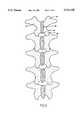
- FIGS. 1, 2, and 3top, side, and posterior views of a vertebral body, a pair of adjacent vertebral bodies, and a sequence of vertebral bodies are shown, respectively.
- the spinal cordis housed in the central canal 10, protected from the posterior side by a shell of bone called the lamina 12.
- the lamina 12includes a rearwardly and downwardly extending portion called the spinous process 16, and laterally extending structures which are referred to as the transverse processes 14.
- the anterior portion of the spinecomprises a set of generally cylindrically shaped bones which are stacked one on top of the other. These portions of the vertebrae are referred to as the vertebral bodies 20, and are each separated from the other by the intervertebral discs 22.
- the pedicles 24comprise bone bridges which couple the anterior vertebral body 20 to the corresponding lamina 12.
- the spinal column of bonesis highly complex in that it includes over twenty bones coupled to one another, housing and protecting critical elements of the nervous system having innumerable peripheral nerves and circulatory bodies in close proximity.
- the spineis a highly flexible structure, capable of a high degree of curvature and twist in nearly every direction. Genetic or developmental irregularities, trauma, chronic stress, tumors, and disease, however, can result in spinal pathologies which either limit this range of motion and/or threaten the critical elements of the nervous system housed within the spinal column.
- a variety of systemshave been disclosed in the art which achieve this immobilization by implanting artificial assemblies in or on the spinal column. These assemblies may be classified as anterior, posterior, or lateral implants.
- Posterior implantsgenerally comprise pairs of rods, which are aligned along the axis which the bones are to be disposed, and which are then attached to the spinal column by either hooks which couple to the lamina or attach to the transverse processes, or by screws which are inserted through the pedicles.
- Rod assembliesgenerally comprise a plurality of such screws which are implanted through the posterior lateral surfaces of the laminae, through the pedicles, and into their respective vertebral bodies. These screws are typically provided with upper portions which comprise coupling means, for receiving and securing an elongate rod therethrough.
- the rodextends along the axis of the spine, coupling to the plurality of screws via their coupling means.
- the rigidity of the rodmay be utilized to align the spine in conformance with a more healthful shape.
- the artcontains a variety of attempts at providing instrumentation which permit enhanced freedom for the surgeon with respect to aligning the screw and the rod, however, most are complex, inadequately reliable, and lack long-term durability. In addition, most generally lack the feature of being constructed to suit the specific anatomical requirements of every patient's spine.
- the Isola(TM) systemwhich is produced by Acromed, suffers from many of these failures in as much as it does not provide the surgeon to freely angulate the rod coupling means of the screw to meet the rod. More specifically, as illustrated in FIGS. 4 and 5, the Isola system consists of a shaft portion which is to be inserted into the patient's pedicle, the shaft having a threaded stem portion rigidly extending upwardly from the top of the shaft portion.
- the interface of the shaft portion and the stem portionincludes a hexagonally shaped annulus for engagement with a torque wrench to permit insertion.
- the surgeonthreadably advances a number of spacer elements onto the stem portion (the spacer elements are threaded washers, some having a non-uniform thickness so as to provide an angular bias or tilt to the overall construct).
- the surgeonplaces the rod coupling means (which is slideably advanced axially onto the rod) onto the stem.
- the rod coupling meansincludes an elongated slot so that the specific position of the rod coupling means relative to the stem may be varied slightly. Once fully positioned, the surgeon secures the assembly together with a top locking nut.
- the Isola systemWhile being modular so as to provide limited variability in the construct, the Isola system has very limited ability to angulate (the stem is rigidly connected to the shaft portion), and what limited ability to angulate that it has entails the use of a plethora of non-uniformly thick spacer elements which are tedious to use in a surgical environment.
- the principal object of the present inventionto provide a pedicle screw and coupling element assembly which provides a polyaxial freedom of implantation angulation with respect to rod reception.
- the polyaxial screw assembly of the present inventioncomprises: a threaded shaft portion for insertion into the pedicle, the top of shaft portion including a convex hemispherical protrusion and a second threading formed on the sides adjacent to the hemispherical protruberance; a stem portion having a threaded post upper portion for receiving spacer elements and/or a rod coupling element thereon, the bottom of said stem portion forming a wider socket portion which includes a concave spherical recess; and a cylindrical locking cuff which is mounted about the top of the shaft and the bottom of the stem to secure the socket recess of the stem on the hemispherical upper portion of the shaft.
- the elongate shank portion of the shaftincludes the threading of a bone screw (standard or otherwise, but suited for proper purchase of the bone).
- the uppermost portion of the shaftcomprises a hemispherically curved convex bubble. This portion may be less than a full hemisphere, but a full hemisphere is preferred.
- a small hexagonal boremay be disposed in the axial center of the hemisphere, coaxial with the shaft, so that a screw driving device (allen wrench, etc.) may be utilized to insert the shaft into the bone.
- a widened annular portion of the shaft, disposed between the two threadingsmay be hexagonal so as to permit the use of a torque wrench or other surgical tool.
- the lateral (circumferential) surface of the shaft at the top endincludes the second threading, for receiving and locking the cuff element thereto.
- the stemcomprises an elongate post portion having an enlarged lower portion which includes a spherically concave recess formed in the bottom thereof.
- the recesshas substantially the same radius of curvature as the hemispherical upper portion of the shaft. Therefore, when the recess is initially permitted to nest on the hemisphere, the stem may be positioned in a variety of different angulations relative to the axis of the shaft portion (through a polyaxial range of configurations from coaxial to substantially non-coaxial).
- the securing cuffcomprises a hollow cylindrical body, having a threading on the bottom half (halves being defined relative to the through axis) of the interior surface thereof. This threading is designed to mate with the threading on the uppermost circumferential portion of the shaft element.
- the upper half of the interior surface of the cuffcomprises a contour, preferably a semi-spherical taper which forms an open ended socket.
- the inner diameter of the open end of the top of the cuffis larger than the diameter of the post portion of the stem, but more narrow than the diameter of the lower socket portion formed at the bottom end of the stem.
- the stem and shaft portionsare initially held coaxial, with the recess of the stem on the hemispherical upper portion of the shaft portion, while the securing cuff is advanced down along the post portion of the stem until the threadings of the cuff and the uppermost exterior surface of the shaft engage.
- the stem and shaftPrior to final tightening, the stem and shaft are thereby held together by the cuff, but each may be angulated relative to the other by virtue of the hemisphere and socket interface.
- a portion of the exterior of the cuffcomprises a hexagonally angled surface contour, such that the cuff may be easily engaged by a torque wrench.
- the upper exterior of the cuffis rounded (with a constant radius of curvature) so that it provides a curvate profile. This permits the secure engagement of similarly rounded spacer elements relative to the top of the cuff element independent of the angular orientation of the post portion of the stem relative to the cuff and shaft (the cuff and shaft remain coaxial).
- spacer elementsmay also be utilized.
- the spacersare annular elements having a diameter which is equivalent to that of the post portion (and are preferrably threaded).
- the bottom surfaces of the spacer elementsare concave, having a radius of curvature equal to that of the upper surface of the cuff. As stated above, this mutual contour permits the spacer to seat securely against the cuff independent of the angulation of the stem.
- the upper surface of the spacer elementis convex, having an equivalent radius of curvature, such that multiple spacers may be nested.
- the advancing the spacer elements downwardly on the stem, and into contact with the cuff, and subsequent tighteningcauses an increase in the total locking force applied to the socket on the hemisphere (the external surface of the lower socket portion of the stem is pulled more tightly into contact with the socket formed by the interior of the cuff).
- the outer lateral surface of the elementsare contoured so as to be engageable by a torque wrench; e.g., having a hexagonal shape.
- the rod coupling element of this assemblycomprises a flat portion having an elongate hole therethrough for coupling to the stem, and a tubular portion which may be slideably advanced along the rod into the proper position. Once in the proper position, the rod coupling means is locked to the rod by a set screw in order to prevent further movement relative to the rod.
- the elongate hole in the flat portionis elongate in nature so that distance from the rod to the stem may be varied.
- This elementfurther includes the concave conformation on the underside thereof so that it may nest securely on the upper surface of either a spacer or directly on the cuff (in the case wherein no spacer is used).
- the first step in the process of implanting this assemblyis to pre-drill the appropriate site in the pedicle to receive the shaft.
- the shaftis then driven into the vertebral body.
- the cuffis then advanced down the stem portion until it reaches the lower socket portion which is wider than the opening at the top of the cuff.
- the recess in the bottom of the stemis then placed on the hemispherical upper portion of the shaft, and the threadings on the top of the shaft and on the interior of the cuff are engaged.
- the stemis then angulated into the appropriate position, and the cuff is locked down, thereby securing the stem relative to the shaft.
- the rod coupling elementis then slideably advanced along the rod into the appropriate position, and the stem placed in the elongate hole thereof.
- the set screw of the rod coupling elementis engaged to lock thereto. (Spacers are threadably advanced onto the stem prior to the insertion of the stem through the elongate hole, if it is determined that they are necessary.) Once the assembly has been properly set, the top locking nut is advanced downwardly along the stem and into position against the top of the rod coupling element, thereby preventing any lateral or axial movement of the stem within the elongate hole.
- screw and coupling element assembly of the present inventionis designed to be compatible with alternative rod systems so that, where necessary, the present invention may be employed to rectify the failures of other systems the implantation of which may have already begun.
- FIG. 1is a top view of a human vertebra, which is representative of the type for which the present invention is useful for coupling thereto a rod apparatus;
- FIG. 2is a side view of a pair of adjacent vertebrae of the type shown in FIG. 1;
- FIG. 3is a posterior view of a sequence of vertebrae of the type shown in FIGS. 1 and 2;
- FIG. 4is a side cross section view of a threaded shaft which is an aspects of the present invention.
- FIG. 5is a side view of a stem portion, having a socket formed at the bottom thereof, which is an aspect of the present invention
- FIG. 6is a side cross section views of a cuff element of the present invention.
- FIG. 7is a side cross section view of a spacer element which is an aspect of the present invention.
- FIG. 8is a perspective view of a rod coupling element which is an aspect of the present invention.
- FIG. 9is a side cross-sectional view of the top locking nut of the present invention.
- FIG. 10is a side view of a fully assembled modular polyaxial pedicle screw of the present invention.
- the modular polyaxial pedicle screw of the present inventionfirst comprises a threaded shaft portion 100 which is inserted into the pedicle.
- the shaft 100includes a lower shank portion 102 which include a bone screw threading 104.
- This threading 104may be standard or otherwise, but is in any case suited for necessary purchase of bone.
- the top 106 of the shaft 100comprises a hemispherical protuberance 108 which forms an upper rounded surface.
- the circumferential surfaces of the upper end 110 of the shaft 100(around the hemisphere 108) includes a second threading 112.
- a widened hexagonal annulus 114which is integrally formed with the shaft 100, and is disposed between the threaded shank 102 and upper portion 110, is provided so that a suitable torque wrench may be employed to drive the shaft 100 into the vertebral body through the pedicle.
- a stem portion 120is shown in a side view. More specifically, the stem 120 comprises an elongate threaded post portion 122 and an enlarged lower socket portion 123.
- the lower portion 123has a larger diameter than the post 122 and includes a spherical recess 124 formed in the bottom thereof.
- the recess 124has substantially the same radius of curvature as the hemispherical upper portion 108 of the shaft 100. This mutual dimension permits the recess 124 to rotate freely over the hemispherical upper portion 108 once the socket 124 is nested thereon, thus permitting the stem 120 to be angulated relative to the shaft 100 (through a polyaxial range from coaxial to substantially non-coaxial).
- the cuff 130is a hollow cylinder and has a threading 132 on the bottom half of the interior surface 134 thereof. This threading 132 is designed to mate with the threading 112 on the uppermost portion 110 of the shaft element 100.
- the upper half of the interior surface 136 of the cuff 130comprises a curvate taper, which is preferably semi-spherical and forms an open ended socket.
- the inner diameter of the open end 138 of the top of the cuff 130is larger than the diameter of the threaded post portion 122 of the stem 120, but more narrow than the diameter of the lower socker portion 123.
- the stem 120 and shaft 100 portionsare initially held coaxial, with the recess 124 of the stem 120 on the hemispherical upper portion 108b of the shaft 100, while the securing cuff 130 is advanced down along the post portion of the stem until the threadings 132, 112 of the cuff 130 and the uppermost exterior surface 110 of the shaft engage.
- the stem 120 and shaft 100Prior to final tightening, are thereby loosely held together by the cuff 130, but each may be angulated relative to the other by virtue of the geometry of the recess 124 and hemispherical upper portion 108 interfacing.
- the total range of angulationis established by the relative diameters of the hemispherical upper portion 108, the lower socker portion of the stem, the post 122, and the opening 138 at the top of the cuff.
- Complete tightening of the cuff 130causes the recess 124 to be crushed onto the hemispherical upper portion 108, thereby preventing any further motion.
- a portion of the exterior 140 of the cuff 130comprises a hexagonally angled surface contour, such that the cuff 130 may be easily engaged by a torque wrench.
- the upper exterior 142 of the cuff 130is rounded (with a constant radius of curvature) so that it provides a curvate profile. This permits the secure engagement of similarly rounded spacer elements (see FIG. 7, and related description hereinbelow) relative to the top of the cuff 130 independent of the angular orientation of the post 122 of the stem 120 relative to the cuff 130 and shaft 100.
- spacer elements 150are provided.
- the spacers 150are annular elements having an inner diameter C--C which is equivalent to that of the post 122.
- the inner surface 152includes a threading 154 which is engageable with the threading of the post 122.
- the bottom surface of the spacer 150is concave, having a radius of curvature equal to that of the tapered upper portion 142 of the cuff 130. This mutual contour permits the spacer 150 to seat securely against the cuff 130 independent of the angulation of the stem 120.
- the upper surface 142 of the spacer 150is convex, having an equivalent radius of curvature, such that multiple spacers 150 may be nested.
- the outer lateral surface 156is contoured so as to be engageable by a torque wrench; e.g., having a hexagonal shape.
- the rod coupling element 160 of this assemblycomprises a flat portion 162 having an elongate hole 164 therethrough for coupling to the stem 120.
- the elongate hole 164has a width equal to that of the post 122, but is elongated to permit variable lateral placement of the post 122 relative to the rod 200.
- the edge (not seen in this illustration) of the elongated hole 164, on the underside of the flat portion,is concavely tapered so as to ideally receive the curvate upper portion of the spacer 150 or the cuff 130.
- the rod coupling element 160further includes a tubular portion 166, the axis of the tube is substantially perpendicular to the elongated axis of the hole 164.
- the rod coupling element 160is positioned on the rod 200 by slideably advancing it therealong. Once in the proper position, the rod coupling element 160 is locked to the rod 200 by a set screw 168 in order to prevent further movement relative to the rod.
- this element 160further includes a concave underside conformation 170 such that it may nest securely on the upper surface of either a spacer 150 or directly on the cuff 130 (in the case wherein no spacer 150 is used).
- a top locking nut 170is utilized to lock the rod coupling element 160 onto the post 122. More particularly, the top locking nut 170 has a bottom surface 172 which is ideally suited to engage and hold the post 122 and the rod coupling element 160 from axial or lateral movement. Specifically, the top locking nut 170 is designed to apply a downward pressure which is sufficient to lock the cuff 130 into the tapered curvate edge of the elongate hole 164 such that the friction locking force of the spacer 150 or cuff 130 thereagainst is sufficient to hold the rod coupling element 160 from lateral, or axial, movement.
- a holeis pre-drilled in the appropriate site in the pedicle in order to receive the shaft 100.
- the shaft 100is then driven into the vertebral body.
- the cuff 130is then advanced down the stem 120 until it reaches the lower socker portion 123.
- the recess 124is then placed onto the hemispherical upper portion 108 of the shaft, and the threadings 112, 132 on the upper portion 110 of the shaft 100 and on the interior of the cuff 130 are engaged.
- the post 122is then angulated into the appropriate position, and the cuff 130 is locked down, thereby securing the stem 120 relative to the shaft 130.
- the lower socket portion 123is crush locked between the cuff 130 and the socket 108.
- spacers 150are positioned above the cuff 130 on the post 122.
- the rod coupling element 160is then slideably advanced along the rod 200 into the appropriate position, and the post 122 is placed in the elongate hole 164 thereof.
- the set screw 168 of the rod coupling element 160is engaged to lock it to the rod 200.
- the top locking nut 180is advanced downwardly along the post 122 and into position against the rod coupling element 160, thereby preventing any lateral or axial movement of the post 122 within the elongate hole 164.
- a complete posterior rod implant systemincludes at least two, and generally four or more, screw assemblies.
- this assemblyas set forth above, may also be used in conjunction with other screw assemblies in the art wherein there is an immediate need for the beneficial properties of this assembly to correct deficiencies in the other assemblies. Therefore, it is anticipated that this modular polyaxial pedicle screw may be used individually, or in conjunction with others.
Landscapes
- Health & Medical Sciences (AREA)
- Orthopedic Medicine & Surgery (AREA)
- Life Sciences & Earth Sciences (AREA)
- Neurology (AREA)
- Surgery (AREA)
- Heart & Thoracic Surgery (AREA)
- Engineering & Computer Science (AREA)
- Biomedical Technology (AREA)
- Nuclear Medicine, Radiotherapy & Molecular Imaging (AREA)
- Medical Informatics (AREA)
- Molecular Biology (AREA)
- Animal Behavior & Ethology (AREA)
- General Health & Medical Sciences (AREA)
- Public Health (AREA)
- Veterinary Medicine (AREA)
- Surgical Instruments (AREA)
Abstract
Description
Claims (10)
Priority Applications (15)
| Application Number | Priority Date | Filing Date | Title |
|---|---|---|---|
| US08/799,720US5725528A (en) | 1997-02-12 | 1997-02-12 | Modular polyaxial locking pedicle screw |
| US08/846,473US5800435A (en) | 1996-10-09 | 1997-05-01 | Modular spinal plate for use with modular polyaxial locking pedicle screws |
| AT97945561TATE346556T1 (en) | 1996-10-09 | 1997-10-07 | MODULAR, MULTI-AXIS PEDICLE SCREW WITH LOCKING |
| CA002268152ACA2268152C (en) | 1996-10-09 | 1997-10-07 | A modular polyaxial locking pedicle screw |
| JP51771398AJP4128224B2 (en) | 1996-10-09 | 1997-10-07 | Modular multi-axis locking stem screw |
| ES05077314TES2297609T3 (en) | 1996-10-09 | 1997-10-07 | PEDICULAR, MODULAR AND POLIAXIAL SCREW. |
| KR10-1999-7003041AKR100531146B1 (en) | 1996-10-09 | 1997-10-07 | A modular polyaxial locking pedicle screw |
| DE69737034TDE69737034T2 (en) | 1996-10-09 | 1997-10-07 | MODULAR CONSTRUCTED, MULTIPLE PEDICELIC SCREW WITH LOCK |
| EP97945561AEP0949887B1 (en) | 1996-10-09 | 1997-10-07 | A modular polyaxial locking pedicle screw |
| PCT/US1997/018155WO1998015233A1 (en) | 1996-10-09 | 1997-10-07 | A modular polyaxial locking pedicle screw |
| AU46731/97AAU731811B2 (en) | 1996-10-09 | 1997-10-07 | A modular polyaxial locking pedicle screw |
| EP05077314AEP1634537B1 (en) | 1996-10-09 | 1997-10-07 | A modular polyaxial locking pedicle screw |
| ES97945561TES2278398T3 (en) | 1996-10-09 | 1997-10-07 | SCREW OF MODULAR POLIAXIAL IMMOBILIZATION PEDICLE. |
| DE69738338TDE69738338T2 (en) | 1996-10-09 | 1997-10-07 | Modular, multi-axis pedicle screw |
| JP2007185087AJP2007301385A (en) | 1996-10-09 | 2007-07-13 | Modular polyaxial locking pedicle screw |
Applications Claiming Priority (1)
| Application Number | Priority Date | Filing Date | Title |
|---|---|---|---|
| US08/799,720US5725528A (en) | 1997-02-12 | 1997-02-12 | Modular polyaxial locking pedicle screw |
Related Child Applications (1)
| Application Number | Title | Priority Date | Filing Date |
|---|---|---|---|
| US08/846,473Continuation-In-PartUS5800435A (en) | 1996-10-09 | 1997-05-01 | Modular spinal plate for use with modular polyaxial locking pedicle screws |
Publications (1)
| Publication Number | Publication Date |
|---|---|
| US5725528Atrue US5725528A (en) | 1998-03-10 |
Family
ID=25176597
Family Applications (1)
| Application Number | Title | Priority Date | Filing Date |
|---|---|---|---|
| US08/799,720Expired - LifetimeUS5725528A (en) | 1996-10-09 | 1997-02-12 | Modular polyaxial locking pedicle screw |
Country Status (1)
| Country | Link |
|---|---|
| US (1) | US5725528A (en) |
Cited By (235)
| Publication number | Priority date | Publication date | Assignee | Title |
|---|---|---|---|---|
| WO1998048719A1 (en) | 1997-05-01 | 1998-11-05 | Techsys Medical, L.L.C. | A modular spinal plate |
| US5984924A (en)* | 1998-10-07 | 1999-11-16 | Isola Implants, Inc. | Bone alignment system having variable orientation bone anchors |
| US6006274A (en)* | 1997-01-30 | 1999-12-21 | 3Com Corporation | Method and apparatus using a pass through personal computer connected to both a local communication link and a computer network for indentifying and synchronizing a preferred computer with a portable computer |
| US6050997A (en)* | 1999-01-25 | 2000-04-18 | Mullane; Thomas S. | Spinal fixation system |
| WO2000024325A1 (en)* | 1998-10-28 | 2000-05-04 | Alphatec Manufacturing, Inc. | Anterior cervical plate and fixation system |
| US6309391B1 (en)* | 2000-03-15 | 2001-10-30 | Sdgi Holding, Inc. | Multidirectional pivoting bone screw and fixation system |
| US6352537B1 (en) | 1998-09-17 | 2002-03-05 | Electro-Biology, Inc. | Method and apparatus for spinal fixation |
| US6423064B1 (en)* | 1999-09-15 | 2002-07-23 | Ulrich Gmbh & Co. Kg | Orthopaedic screw variable angle connection to a longitudinal support |
| US20020133159A1 (en)* | 2000-12-08 | 2002-09-19 | Jackson Roger P. | Closure for open-headed medical implant |
| US20020156474A1 (en)* | 2001-04-20 | 2002-10-24 | Michael Wack | Polyaxial locking plate |
| US20030055426A1 (en)* | 2001-09-14 | 2003-03-20 | John Carbone | Biased angulation bone fixation assembly |
| US20030093078A1 (en)* | 2001-09-28 | 2003-05-15 | Stephen Ritland | Connection rod for screw or hook polyaxial system and method of use |
| US20030153912A1 (en)* | 2000-06-30 | 2003-08-14 | Henry Graf | Intervertebral connecting device |
| US20030171751A1 (en)* | 2002-02-20 | 2003-09-11 | Stephen Ritland | Pedicle screw connector apparatus and method |
| US20040002708A1 (en)* | 2002-05-08 | 2004-01-01 | Stephen Ritland | Dynamic fixation device and method of use |
| FR2842093A1 (en)* | 2002-07-12 | 2004-01-16 | Scient X | BONE ANCHORING DEVICE WITH SPHERICAL JOINT |
| US20040030337A1 (en)* | 2002-04-09 | 2004-02-12 | Neville Alleyne | Bone fixation apparatus |
| US6709434B1 (en) | 1998-07-30 | 2004-03-23 | Sofamor S.N.C. | Spinal osteosynthesis device |
| US20040064140A1 (en)* | 2000-11-07 | 2004-04-01 | Jean Taylor | Vertebral arthrodesis equipment |
| US6716214B1 (en) | 2003-06-18 | 2004-04-06 | Roger P. Jackson | Polyaxial bone screw with spline capture connection |
| US20040079253A1 (en)* | 1990-02-05 | 2004-04-29 | Creo Il Ltd. | Closed loop ceps-press control systems |
| US20040092934A1 (en)* | 2002-04-24 | 2004-05-13 | Howland Robert S. | Multi selective axis spinal fixation system |
| US6736816B2 (en)* | 2000-06-30 | 2004-05-18 | Stephen Ritland | Polyaxial connection device and method |
| US6770075B2 (en) | 2001-05-17 | 2004-08-03 | Robert S. Howland | Spinal fixation apparatus with enhanced axial support and methods for use |
| US20040153077A1 (en)* | 2000-11-10 | 2004-08-05 | Lutz Biedermann | Bone screw |
| US20040167526A1 (en)* | 2002-09-06 | 2004-08-26 | Roger P. Jackson | Closure for rod receiving orthopedic implant having left handed thread removal |
| US20040172032A1 (en)* | 2002-09-06 | 2004-09-02 | Jackson Roger P. | Anti-splay medical implant closure with multi-surface removal aperture |
| US20040172020A1 (en)* | 2001-04-06 | 2004-09-02 | Jacques Beaurain | Spinal osteosynthesis device and preparation method |
| EP1257218A4 (en)* | 2000-02-16 | 2004-09-15 | Ebi Lp | Method and system for spinal fixation |
| US20040181223A1 (en)* | 2001-09-28 | 2004-09-16 | Stephen Ritland | Adjustable rod and connector device and method of use |
| US20040199164A1 (en)* | 2002-09-06 | 2004-10-07 | Jackson Roger P. | Helical wound mechanically interlocking mating guide and advancement structure |
| US20040210216A1 (en)* | 2003-04-17 | 2004-10-21 | Farris Robert A | Spinal fixation system and method |
| US20040236330A1 (en)* | 2003-05-22 | 2004-11-25 | Thomas Purcell | Variable angle spinal screw assembly |
| US20040243128A1 (en)* | 2001-05-17 | 2004-12-02 | Howland Robert S. | Selective axis posterior lumbar spinal plating fixation apparatus and methods for use |
| US20040254428A1 (en)* | 2003-05-22 | 2004-12-16 | Stephen Ritland | Intermuscular guide for retractor insertion and method of use |
| US20040254577A1 (en)* | 2001-10-18 | 2004-12-16 | Joel Delecrin | Progressive approach osteosynthesis device and preassembly method |
| US20050010215A1 (en)* | 2001-10-18 | 2005-01-13 | Joel Delecrin | Plate for osteosynthesis device and preassembling method |
| US20050049589A1 (en)* | 2003-08-28 | 2005-03-03 | Jackson Roger P. | Polyaxial bone screw apparatus |
| US20050107788A1 (en)* | 2001-12-12 | 2005-05-19 | Jacques Beaurain | Implant for osseous anchoring with polyaxial head |
| US20050154391A1 (en)* | 2003-12-30 | 2005-07-14 | Thomas Doherty | Bone anchor assemblies |
| US20050159750A1 (en)* | 2003-12-30 | 2005-07-21 | Thomas Doherty | Bone anchor assemblies and methods of manufacturing bone anchor assemblies |
| US20050182410A1 (en)* | 2002-09-06 | 2005-08-18 | Jackson Roger P. | Helical guide and advancement flange with radially loaded lip |
| US20050228233A1 (en)* | 2000-09-29 | 2005-10-13 | Stephen Ritland | Method and device for microsurgical intermuscular spinal surgery |
| US20050234454A1 (en)* | 2003-09-24 | 2005-10-20 | Chin Kingsley R | Multi-axial screw with a spherical landing |
| US20050240181A1 (en)* | 2004-04-23 | 2005-10-27 | Boomer Mark C | Spinal implant connectors |
| US20050240185A1 (en)* | 2004-04-23 | 2005-10-27 | Depuy Spine Sarl | Spinal fixation plates and plate extensions |
| US6964666B2 (en) | 2003-04-09 | 2005-11-15 | Jackson Roger P | Polyaxial bone screw locking mechanism |
| US6966910B2 (en) | 2002-04-05 | 2005-11-22 | Stephen Ritland | Dynamic fixation device and method of use |
| US20050277919A1 (en)* | 2004-05-28 | 2005-12-15 | Depuy Spine, Inc. | Anchoring systems and methods for correcting spinal deformities |
| US20050288668A1 (en)* | 2002-06-24 | 2005-12-29 | Bernhard Brinkhaus | Spinal column support system |
| US20060009773A1 (en)* | 2002-09-06 | 2006-01-12 | Jackson Roger P | Helical interlocking mating guide and advancement structure |
| US20060036252A1 (en)* | 2004-08-12 | 2006-02-16 | Baynham Bret O | Polyaxial screw |
| US20060036242A1 (en)* | 2004-08-10 | 2006-02-16 | Nilsson C M | Screw and rod fixation system |
| US20060064092A1 (en)* | 2001-05-17 | 2006-03-23 | Howland Robert S | Selective axis serrated rod low profile spinal fixation system |
| US20060063978A1 (en)* | 2004-09-20 | 2006-03-23 | Stephen Ritland | Opposing parallel bladed retractor and method of use |
| US20060074419A1 (en)* | 2004-10-05 | 2006-04-06 | Taylor Harold S | Spinal implants with multi-axial anchor assembly and methods |
| US20060084979A1 (en)* | 2003-04-09 | 2006-04-20 | Jackson Roger P | Polyaxial bone screw with uploaded threaded shank and method of assembly and use |
| US20060084989A1 (en)* | 2004-10-05 | 2006-04-20 | Sdgi Holdings, Inc. | Multi-axial anchor assemblies for spinal implants and methods |
| US20060095038A1 (en)* | 2004-11-03 | 2006-05-04 | Jackson Roger P | Polyaxial bone screw |
| US20060100621A1 (en)* | 2004-11-10 | 2006-05-11 | Jackson Roger P | Polyaxial bone screw with discontinuous helically wound capture connection |
| US20060106382A1 (en)* | 2004-05-26 | 2006-05-18 | Jose Gournay | Spinal implant apparatus |
| US20060149240A1 (en)* | 2004-11-23 | 2006-07-06 | Jackson Roger P | Polyaxial bone screw with multi-part shank retainer |
| US20060149231A1 (en)* | 2004-12-13 | 2006-07-06 | Rsb Spine Llc | Bone fastener assembly for bone retention apparatus |
| US20060217716A1 (en)* | 2005-03-22 | 2006-09-28 | Baker Daniel R | Spinal fixation locking mechanism |
| US20060241603A1 (en)* | 2003-06-18 | 2006-10-26 | Jackson Roger P | Polyaxial bone screw assembly with fixed retaining structure |
| US20060247625A1 (en)* | 2005-04-29 | 2006-11-02 | Sdgi Holdings, Inc. | System, devices and method for augmenting existing fusion constructs |
| US20060264933A1 (en)* | 2005-05-04 | 2006-11-23 | Baker Daniel R | Multistage spinal fixation locking mechanism |
| US20060271047A1 (en)* | 2005-05-10 | 2006-11-30 | Jackson Roger P | Polyaxial bone screw with compound articulation |
| US20060276789A1 (en)* | 2005-05-27 | 2006-12-07 | Jackson Roger P | Polyaxial bone screw with shank articulation pressure insert and method |
| US20060293660A1 (en)* | 2005-06-03 | 2006-12-28 | Lewis Edward L | Connector for attaching an alignment rod to a bone structure |
| US20070043365A1 (en)* | 2005-07-19 | 2007-02-22 | Stephen Ritland | Rod extension for extending fusion construct |
| US20070043358A1 (en)* | 2005-08-05 | 2007-02-22 | Sdgi Holdings, Inc. | Coupling assemblies for spinal implants |
| US20070055244A1 (en)* | 2004-02-27 | 2007-03-08 | Jackson Roger P | Dynamic fixation assemblies with inner core and outer coil-like member |
| US7214186B2 (en) | 2000-09-29 | 2007-05-08 | Stephen Ritland | Method and device for retractor for microsurgical intermuscular lumbar arthrodesis |
| US20070161995A1 (en)* | 2005-10-06 | 2007-07-12 | Trautwein Frank T | Polyaxial Screw |
| US20070250171A1 (en)* | 2006-04-24 | 2007-10-25 | Sdgi Holdings, Inc. | Expandable intervertebral devices and methods of use |
| US20070255415A1 (en)* | 2006-05-01 | 2007-11-01 | Sdgi Holdings, Inc. | Expandable intervertebral spacers and methods of use |
| US20070255413A1 (en)* | 2006-04-27 | 2007-11-01 | Sdgi Holdings, Inc. | Expandable intervertebral spacers and methods of use |
| US20070270960A1 (en)* | 2006-04-24 | 2007-11-22 | Sdgi Holdings, Inc. | Extendable anchor in a vertebral implant and methods of use |
| US20070270964A1 (en)* | 2006-04-27 | 2007-11-22 | Sdgi Holdings, Inc. | Expandable vertebral implant and methods of use |
| US20070288012A1 (en)* | 2006-04-21 | 2007-12-13 | Dennis Colleran | Dynamic motion spinal stabilization system and device |
| US20080004626A1 (en)* | 2006-05-26 | 2008-01-03 | Glazer Paul A | Orthopedic coil screw insert |
| US20080009862A1 (en)* | 2006-06-16 | 2008-01-10 | Zimmer Spine, Inc. | Removable polyaxial housing for a pedicle screw |
| US20080015579A1 (en)* | 2006-04-28 | 2008-01-17 | Whipple Dale E | Large diameter bone anchor assembly |
| US20080015576A1 (en)* | 2006-04-28 | 2008-01-17 | Whipple Dale E | Large diameter bone anchor assembly |
| US20080021464A1 (en)* | 2006-07-19 | 2008-01-24 | Joshua Morin | System and method for a spinal implant locking assembly |
| US7322981B2 (en) | 2003-08-28 | 2008-01-29 | Jackson Roger P | Polyaxial bone screw with split retainer ring |
| US20080058808A1 (en)* | 2006-06-14 | 2008-03-06 | Spartek Medical, Inc. | Implant system and method to treat degenerative disorders of the spine |
| US20080147122A1 (en)* | 2006-10-12 | 2008-06-19 | Jackson Roger P | Dynamic stabilization connecting member with molded inner segment and surrounding external elastomer |
| US20080161926A1 (en)* | 2006-10-16 | 2008-07-03 | Warsaw Orthopedic, Inc. | Implants with Helical Supports and Methods of Use for Spacing Vertebral Members |
| US20080177323A1 (en)* | 2006-10-18 | 2008-07-24 | Null William B | Orthopedic revision connector |
| US20080183220A1 (en)* | 2007-01-19 | 2008-07-31 | Glazer Paul A | Orthopedic screw insert |
| US20080188898A1 (en)* | 2004-11-23 | 2008-08-07 | Jackson Roger P | Polyaxial bone screw with multi-part shank retainer and pressure insert |
| US20080234757A1 (en)* | 2007-02-27 | 2008-09-25 | Jacofsky Marc C | Modular pedicle screw system |
| US20080262318A1 (en)* | 2007-04-17 | 2008-10-23 | K2M, Inc. | Minimally open interbody access retraction device and surgical method |
| US20080262556A1 (en)* | 2007-02-27 | 2008-10-23 | Jacofsky Marc C | Modular polyaxial pedicle screw system |
| US20080306556A1 (en)* | 2007-06-05 | 2008-12-11 | Spartek Medical, Inc. | Bone anchor with a curved mounting element for a dynamic stabilization and motion preservation spinal implantation system and method |
| US20080306545A1 (en)* | 2007-06-05 | 2008-12-11 | Spartek Medical, Inc. | Deflection rod system for a dynamic stabilization and motion preservation spinal implantation system and method |
| US20080312697A1 (en)* | 2007-06-15 | 2008-12-18 | Robert Reid, Inc. | System and Method for Polyaxially Adjustable Bone Anchorage |
| US20080319482A1 (en)* | 2007-01-18 | 2008-12-25 | Jackson Roger P | Dynamic fixation assemblies with pre-tensioned cord segments |
| US20090062866A1 (en)* | 2003-06-18 | 2009-03-05 | Jackson Roger P | Polyaxial bone anchor with helical capture connection, insert and dual locking assembly |
| US20090105832A1 (en)* | 2007-06-08 | 2009-04-23 | Ldr Medical | Intersomatic cage, intervertebral prosthesis, anchoring device and implantation instruments |
| US7533933B2 (en) | 2004-08-12 | 2009-05-19 | Cybex Industrial, Ltd. | Child seat for a motor vehicle |
| US20100030271A1 (en)* | 2008-02-26 | 2010-02-04 | Spartek Medical, Inc. | Modular in-line deflection rod and bone anchor system and method for dynamic stabilization of the spine |
| US20100030270A1 (en)* | 2007-06-05 | 2010-02-04 | Spartek Medical, Inc. | Dynamic spinal rod assembly and method for dynamic stabilization of the spine |
| US20100030274A1 (en)* | 2007-06-05 | 2010-02-04 | Spartek Medical, Inc. | Dynamic spinal rod and method for dynamic stabilization of the spine |
| US20100030267A1 (en)* | 2007-06-05 | 2010-02-04 | Spartek Medical, Inc. | Surgical tool and method for implantation of a dynamic bone anchor |
| US20100030224A1 (en)* | 2008-02-26 | 2010-02-04 | Spartek Medical, Inc. | Surgical tool and method for connecting a dynamic bone anchor and dynamic vertical rod |
| US20100030273A1 (en)* | 2008-02-26 | 2010-02-04 | Spartek Medical, Inc. | Versatile polyaxial connector assembly and method for dynamic stabilization of the spine |
| US20100036436A1 (en)* | 2008-02-26 | 2010-02-11 | Spartek Medical, Inc. | Load-sharing bone anchor having a durable compliant member and method for dynamic stabilization of the spine |
| US20100036437A1 (en)* | 2008-02-26 | 2010-02-11 | Spartek Medical, Inc. | Load-sharing bone anchor having a deflectable post with a compliant ring and method for stabilization of the spine |
| US20100036435A1 (en)* | 2008-02-26 | 2010-02-11 | Spartek Medical, Inc. | Load-sharing bone anchor having a deflectable post and method for dynamic stabilization of the spine |
| US20100087880A1 (en)* | 2004-02-17 | 2010-04-08 | Facet Solutions, Inc. | Facet Joint Replacement Instruments and Methods |
| US20100125302A1 (en)* | 2008-11-14 | 2010-05-20 | Hammill Sr John E | Locking Polyaxial Ball And Socket Fastener |
| US20100137920A1 (en)* | 2007-05-16 | 2010-06-03 | Hammill Sr John E | Pedicle screw implant system |
| US20100168795A1 (en)* | 2008-02-26 | 2010-07-01 | Spartek Medical, Inc. | Load-sharing bone anchor having a natural center of rotation and method for dynamic stabilization of the spine |
| US7789896B2 (en) | 2005-02-22 | 2010-09-07 | Jackson Roger P | Polyaxial bone screw assembly |
| US7794477B2 (en) | 2004-10-05 | 2010-09-14 | Warsaw Orthopedic, Inc. | Spinal implants and methods with extended multi-axial anchor assemblies |
| US7794481B2 (en) | 2005-04-22 | 2010-09-14 | Warsaw Orthopedic, Inc. | Force limiting coupling assemblies for spinal implants |
| US7833250B2 (en) | 2004-11-10 | 2010-11-16 | Jackson Roger P | Polyaxial bone screw with helically wound capture connection |
| US20100291507A1 (en)* | 2009-05-13 | 2010-11-18 | Custom Spine, Inc. | Polyaxial Dental Implant |
| US20100312288A1 (en)* | 2007-05-16 | 2010-12-09 | Hammill Sr John E | Thread-thru polyaxial pedicle screw system |
| US7854752B2 (en) | 2004-08-09 | 2010-12-21 | Theken Spine, Llc | System and method for dynamic skeletal stabilization |
| US20110009911A1 (en)* | 2008-11-14 | 2011-01-13 | Hammill Sr John E | Locking polyaxial ball and socket fastener |
| US7901437B2 (en) | 2007-01-26 | 2011-03-08 | Jackson Roger P | Dynamic stabilization member with molded connection |
| US20110093021A1 (en)* | 2009-10-16 | 2011-04-21 | Jonathan Fanger | Bone Anchor Assemblies and Methods of Manufacturing and Use Thereof |
| US7942910B2 (en) | 2007-05-16 | 2011-05-17 | Ortho Innovations, Llc | Polyaxial bone screw |
| US7942909B2 (en) | 2009-08-13 | 2011-05-17 | Ortho Innovations, Llc | Thread-thru polyaxial pedicle screw system |
| US7942911B2 (en) | 2007-05-16 | 2011-05-17 | Ortho Innovations, Llc | Polyaxial bone screw |
| US20110118783A1 (en)* | 2009-11-16 | 2011-05-19 | Spartek Medical, Inc. | Load-sharing bone anchor having a flexible post and method for dynamic stabilization of the spine |
| US7951170B2 (en) | 2007-05-31 | 2011-05-31 | Jackson Roger P | Dynamic stabilization connecting member with pre-tensioned solid core |
| US7959564B2 (en) | 2006-07-08 | 2011-06-14 | Stephen Ritland | Pedicle seeker and retractor, and methods of use |
| US7963978B2 (en) | 2007-06-05 | 2011-06-21 | Spartek Medical, Inc. | Method for implanting a deflection rod system and customizing the deflection rod system for a particular patient need for dynamic stabilization and motion preservation spinal implantation system |
| US8012177B2 (en) | 2007-02-12 | 2011-09-06 | Jackson Roger P | Dynamic stabilization assembly with frusto-conical connection |
| US8021396B2 (en) | 2007-06-05 | 2011-09-20 | Spartek Medical, Inc. | Configurable dynamic spinal rod and method for dynamic stabilization of the spine |
| US20110230920A1 (en)* | 2010-03-19 | 2011-09-22 | K2M, Inc. | Spinal fixation apparatus and methods |
| US8025681B2 (en) | 2006-03-29 | 2011-09-27 | Theken Spine, Llc | Dynamic motion spinal stabilization system |
| US8052724B2 (en) | 2003-06-18 | 2011-11-08 | Jackson Roger P | Upload shank swivel head bone screw spinal implant |
| US8057517B2 (en) | 2008-02-26 | 2011-11-15 | Spartek Medical, Inc. | Load-sharing component having a deflectable post and centering spring and method for dynamic stabilization of the spine |
| US8066739B2 (en) | 2004-02-27 | 2011-11-29 | Jackson Roger P | Tool system for dynamic spinal implants |
| US8097024B2 (en) | 2008-02-26 | 2012-01-17 | Spartek Medical, Inc. | Load-sharing bone anchor having a deflectable post and method for stabilization of the spine |
| US8100915B2 (en) | 2004-02-27 | 2012-01-24 | Jackson Roger P | Orthopedic implant rod reduction tool set and method |
| US8105368B2 (en) | 2005-09-30 | 2012-01-31 | Jackson Roger P | Dynamic stabilization connecting member with slitted core and outer sleeve |
| US8114134B2 (en) | 2007-06-05 | 2012-02-14 | Spartek Medical, Inc. | Spinal prosthesis having a three bar linkage for motion preservation and dynamic stabilization of the spine |
| US8152810B2 (en) | 2004-11-23 | 2012-04-10 | Jackson Roger P | Spinal fixation tool set and method |
| US20120209332A1 (en)* | 2011-02-14 | 2012-08-16 | Pioneer Surgical Technology, Inc. | Spinal Fixation System And Method |
| US8257397B2 (en) | 2009-12-02 | 2012-09-04 | Spartek Medical, Inc. | Low profile spinal prosthesis incorporating a bone anchor having a deflectable post and a compound spinal rod |
| US8257398B2 (en) | 2003-06-18 | 2012-09-04 | Jackson Roger P | Polyaxial bone screw with cam capture |
| US8267979B2 (en) | 2008-02-26 | 2012-09-18 | Spartek Medical, Inc. | Load-sharing bone anchor having a deflectable post and axial spring and method for dynamic stabilization of the spine |
| US8292926B2 (en) | 2005-09-30 | 2012-10-23 | Jackson Roger P | Dynamic stabilization connecting member with elastic core and outer sleeve |
| US8308782B2 (en) | 2004-11-23 | 2012-11-13 | Jackson Roger P | Bone anchors with longitudinal connecting member engaging inserts and closures for fixation and optional angulation |
| US8337536B2 (en) | 2008-02-26 | 2012-12-25 | Spartek Medical, Inc. | Load-sharing bone anchor having a deflectable post with a compliant ring and method for stabilization of the spine |
| US8353932B2 (en) | 2005-09-30 | 2013-01-15 | Jackson Roger P | Polyaxial bone anchor assembly with one-piece closure, pressure insert and plastic elongate member |
| US8361129B2 (en) | 2006-04-28 | 2013-01-29 | Depuy Spine, Inc. | Large diameter bone anchor assembly |
| US8366745B2 (en) | 2007-05-01 | 2013-02-05 | Jackson Roger P | Dynamic stabilization assembly having pre-compressed spacers with differential displacements |
| US8377102B2 (en) | 2003-06-18 | 2013-02-19 | Roger P. Jackson | Polyaxial bone anchor with spline capture connection and lower pressure insert |
| US8398682B2 (en) | 2003-06-18 | 2013-03-19 | Roger P. Jackson | Polyaxial bone screw assembly |
| US8430916B1 (en) | 2012-02-07 | 2013-04-30 | Spartek Medical, Inc. | Spinal rod connectors, methods of use, and spinal prosthesis incorporating spinal rod connectors |
| US8444681B2 (en) | 2009-06-15 | 2013-05-21 | Roger P. Jackson | Polyaxial bone anchor with pop-on shank, friction fit retainer and winged insert |
| US8475498B2 (en) | 2007-01-18 | 2013-07-02 | Roger P. Jackson | Dynamic stabilization connecting member with cord connection |
| US8518085B2 (en) | 2010-06-10 | 2013-08-27 | Spartek Medical, Inc. | Adaptive spinal rod and methods for stabilization of the spine |
| US8545538B2 (en) | 2005-12-19 | 2013-10-01 | M. Samy Abdou | Devices and methods for inter-vertebral orthopedic device placement |
| US8556938B2 (en) | 2009-06-15 | 2013-10-15 | Roger P. Jackson | Polyaxial bone anchor with non-pivotable retainer and pop-on shank, some with friction fit |
| US8591515B2 (en) | 2004-11-23 | 2013-11-26 | Roger P. Jackson | Spinal fixation tool set and method |
| US20140074169A1 (en)* | 2012-09-13 | 2014-03-13 | Warsaw Orthopedic, Inc. | Spinal correction system and method |
| US20140114365A1 (en)* | 2005-05-10 | 2014-04-24 | Acumed Llc | Bone connector with pivotable joint |
| US20140114358A1 (en)* | 2010-04-05 | 2014-04-24 | David L. Brumfield | Fully-Adjustable Bone Fixation Device |
| US8740980B2 (en) | 2011-01-27 | 2014-06-03 | Warsaw Orthopedic, Inc. | Expandable medical implant |
| US8814913B2 (en) | 2002-09-06 | 2014-08-26 | Roger P Jackson | Helical guide and advancement flange with break-off extensions |
| US8814911B2 (en) | 2003-06-18 | 2014-08-26 | Roger P. Jackson | Polyaxial bone screw with cam connection and lock and release insert |
| US8845649B2 (en) | 2004-09-24 | 2014-09-30 | Roger P. Jackson | Spinal fixation tool set and method for rod reduction and fastener insertion |
| US8845691B2 (en) | 2003-09-01 | 2014-09-30 | Ldr Medical | Osseous anchoring implant with a polyaxial head and method for installing the implant |
| US8852239B2 (en) | 2013-02-15 | 2014-10-07 | Roger P Jackson | Sagittal angle screw with integral shank and receiver |
| US8911479B2 (en) | 2012-01-10 | 2014-12-16 | Roger P. Jackson | Multi-start closures for open implants |
| US8911478B2 (en) | 2012-11-21 | 2014-12-16 | Roger P. Jackson | Splay control closure for open bone anchor |
| US8911477B2 (en) | 2007-10-23 | 2014-12-16 | Roger P. Jackson | Dynamic stabilization member with end plate support and cable core extension |
| US8926672B2 (en) | 2004-11-10 | 2015-01-06 | Roger P. Jackson | Splay control closure for open bone anchor |
| US8926670B2 (en) | 2003-06-18 | 2015-01-06 | Roger P. Jackson | Polyaxial bone screw assembly |
| US8979904B2 (en) | 2007-05-01 | 2015-03-17 | Roger P Jackson | Connecting member with tensioned cord, low profile rigid sleeve and spacer with torsion control |
| US8998959B2 (en) | 2009-06-15 | 2015-04-07 | Roger P Jackson | Polyaxial bone anchors with pop-on shank, fully constrained friction fit retainer and lock and release insert |
| US8998961B1 (en) | 2009-02-26 | 2015-04-07 | Lanx, Inc. | Spinal rod connector and methods |
| US9050139B2 (en) | 2004-02-27 | 2015-06-09 | Roger P. Jackson | Orthopedic implant rod reduction tool set and method |
| US9050148B2 (en) | 2004-02-27 | 2015-06-09 | Roger P. Jackson | Spinal fixation tool attachment structure |
| US9168069B2 (en) | 2009-06-15 | 2015-10-27 | Roger P. Jackson | Polyaxial bone anchor with pop-on shank and winged insert with lower skirt for engaging a friction fit retainer |
| US9198695B2 (en) | 2010-08-30 | 2015-12-01 | Zimmer Spine, Inc. | Polyaxial pedicle screw |
| US9216041B2 (en) | 2009-06-15 | 2015-12-22 | Roger P. Jackson | Spinal connecting members with tensioned cords and rigid sleeves for engaging compression inserts |
| US9216039B2 (en) | 2004-02-27 | 2015-12-22 | Roger P. Jackson | Dynamic spinal stabilization assemblies, tool set and method |
| US9414863B2 (en) | 2005-02-22 | 2016-08-16 | Roger P. Jackson | Polyaxial bone screw with spherical capture, compression insert and alignment and retention structures |
| US9453526B2 (en) | 2013-04-30 | 2016-09-27 | Degen Medical, Inc. | Bottom-loading anchor assembly |
| US9451989B2 (en) | 2007-01-18 | 2016-09-27 | Roger P Jackson | Dynamic stabilization members with elastic and inelastic sections |
| US9451993B2 (en) | 2014-01-09 | 2016-09-27 | Roger P. Jackson | Bi-radial pop-on cervical bone anchor |
| US9480517B2 (en) | 2009-06-15 | 2016-11-01 | Roger P. Jackson | Polyaxial bone anchor with pop-on shank, shank, friction fit retainer, winged insert and low profile edge lock |
| US9566092B2 (en) | 2013-10-29 | 2017-02-14 | Roger P. Jackson | Cervical bone anchor with collet retainer and outer locking sleeve |
| US9597119B2 (en) | 2014-06-04 | 2017-03-21 | Roger P. Jackson | Polyaxial bone anchor with polymer sleeve |
| US9668771B2 (en) | 2009-06-15 | 2017-06-06 | Roger P Jackson | Soft stabilization assemblies with off-set connector |
| US9717533B2 (en) | 2013-12-12 | 2017-08-01 | Roger P. Jackson | Bone anchor closure pivot-splay control flange form guide and advancement structure |
| US9907574B2 (en) | 2008-08-01 | 2018-03-06 | Roger P. Jackson | Polyaxial bone anchors with pop-on shank, friction fit fully restrained retainer, insert and tool receiving features |
| US9980753B2 (en) | 2009-06-15 | 2018-05-29 | Roger P Jackson | pivotal anchor with snap-in-place insert having rotation blocking extensions |
| US10039578B2 (en) | 2003-12-16 | 2018-08-07 | DePuy Synthes Products, Inc. | Methods and devices for minimally invasive spinal fixation element placement |
| US10058354B2 (en) | 2013-01-28 | 2018-08-28 | Roger P. Jackson | Pivotal bone anchor assembly with frictional shank head seating surfaces |
| US10064658B2 (en) | 2014-06-04 | 2018-09-04 | Roger P. Jackson | Polyaxial bone anchor with insert guides |
| US10149674B2 (en) | 2015-08-12 | 2018-12-11 | K2M, Inc. | Orthopedic surgical system including surgical access systems, distraction systems, and methods of using same |
| US10194951B2 (en) | 2005-05-10 | 2019-02-05 | Roger P. Jackson | Polyaxial bone anchor with compound articulation and pop-on shank |
| US10299839B2 (en) | 2003-12-16 | 2019-05-28 | Medos International Sárl | Percutaneous access devices and bone anchor assemblies |
| US20190175226A1 (en)* | 2017-02-10 | 2019-06-13 | Medos International Sarl | Tandem Rod Connectors and Related Methods |
| US10363070B2 (en) | 2009-06-15 | 2019-07-30 | Roger P. Jackson | Pivotal bone anchor assemblies with pressure inserts and snap on articulating retainers |
| US10383660B2 (en) | 2007-05-01 | 2019-08-20 | Roger P. Jackson | Soft stabilization assemblies with pretensioned cords |
| US10426521B2 (en)* | 2015-04-24 | 2019-10-01 | Medicrea International | Vertebral osteosynthesis equipment |
| US10499894B2 (en) | 2015-08-12 | 2019-12-10 | K2M, Inc. | Orthopedic surgical system including surgical access systems, distraction systems, and methods of using same |
| US10543107B2 (en) | 2009-12-07 | 2020-01-28 | Samy Abdou | Devices and methods for minimally invasive spinal stabilization and instrumentation |
| US10548740B1 (en) | 2016-10-25 | 2020-02-04 | Samy Abdou | Devices and methods for vertebral bone realignment |
| US10575961B1 (en) | 2011-09-23 | 2020-03-03 | Samy Abdou | Spinal fixation devices and methods of use |
| US10695105B2 (en) | 2012-08-28 | 2020-06-30 | Samy Abdou | Spinal fixation devices and methods of use |
| US10729469B2 (en) | 2006-01-09 | 2020-08-04 | Roger P. Jackson | Flexible spinal stabilization assembly with spacer having off-axis core member |
| US10857003B1 (en) | 2015-10-14 | 2020-12-08 | Samy Abdou | Devices and methods for vertebral stabilization |
| US10918498B2 (en) | 2004-11-24 | 2021-02-16 | Samy Abdou | Devices and methods for inter-vertebral orthopedic device placement |
| US10966761B2 (en) | 2017-03-28 | 2021-04-06 | Medos International Sarl | Articulating implant connectors and related methods |
| US10973648B1 (en) | 2016-10-25 | 2021-04-13 | Samy Abdou | Devices and methods for vertebral bone realignment |
| US11006982B2 (en) | 2012-02-22 | 2021-05-18 | Samy Abdou | Spinous process fixation devices and methods of use |
| US11058463B2 (en) | 2016-05-18 | 2021-07-13 | Medos International Sarl | Implant connectors and related methods |
| US11076890B2 (en) | 2017-12-01 | 2021-08-03 | Medos International Sàrl | Rod-to-rod connectors having robust rod closure mechanisms and related methods |
| US11160583B2 (en) | 2016-12-19 | 2021-11-02 | Medos International Sarl | Offset rods, offset rod connectors, and related methods |
| US11173040B2 (en) | 2012-10-22 | 2021-11-16 | Cogent Spine, LLC | Devices and methods for spinal stabilization and instrumentation |
| US11179248B2 (en) | 2018-10-02 | 2021-11-23 | Samy Abdou | Devices and methods for spinal implantation |
| US11229457B2 (en) | 2009-06-15 | 2022-01-25 | Roger P. Jackson | Pivotal bone anchor assembly with insert tool deployment |
| US11259845B2 (en) | 2017-03-30 | 2022-03-01 | K2M, Inc. | Bone anchor apparatus and method of use thereof |
| US11298156B2 (en) | 2017-03-30 | 2022-04-12 | K2M, Inc. | Modular screw |
| US11382676B2 (en) | 2017-03-28 | 2022-07-12 | Medos International Sarl | Articulating implant connectors and related methods |
| US11419639B2 (en) | 2017-03-30 | 2022-08-23 | K2M, Inc. | Modular offset screw |
| US11419642B2 (en) | 2003-12-16 | 2022-08-23 | Medos International Sarl | Percutaneous access devices and bone anchor assemblies |
| US11596451B2 (en) | 2016-05-18 | 2023-03-07 | Medos International Sarl | Implant connectors and related methods |
| US11751915B2 (en) | 2021-07-09 | 2023-09-12 | Roger P. Jackson | Modular spinal fixation system with bottom-loaded universal shank heads |
| US12114898B2 (en) | 2020-11-19 | 2024-10-15 | K2M, Inc. | Modular head assembly for spinal fixation |
| US12262921B2 (en) | 2020-06-26 | 2025-04-01 | K2M, Inc. | Modular head assembly |
| US12383311B2 (en) | 2010-05-14 | 2025-08-12 | Roger P. Jackson | Pivotal bone anchor assembly and method for use thereof |
Citations (7)
| Publication number | Priority date | Publication date | Assignee | Title |
|---|---|---|---|---|
| US4946458A (en)* | 1986-04-25 | 1990-08-07 | Harms Juergen | Pedicle screw |
| US5207678A (en)* | 1989-07-20 | 1993-05-04 | Prufer | Pedicle screw and receiver member therefore |
| US5344422A (en)* | 1989-10-30 | 1994-09-06 | Synthes (U.S.A.) | Pedicular screw clamp |
| US5360431A (en)* | 1990-04-26 | 1994-11-01 | Cross Medical Products | Transpedicular screw system and method of use |
| US5443467A (en)* | 1993-03-10 | 1995-08-22 | Biedermann Motech Gmbh | Bone screw |
| US5476464A (en)* | 1993-02-25 | 1995-12-19 | Howmedica Gmbh | Device for setting a spine |
| US5501684A (en)* | 1992-06-25 | 1996-03-26 | Synthes (U.S.A.) | Osteosynthetic fixation device |
- 1997
- 1997-02-12USUS08/799,720patent/US5725528A/ennot_activeExpired - Lifetime
Patent Citations (7)
| Publication number | Priority date | Publication date | Assignee | Title |
|---|---|---|---|---|
| US4946458A (en)* | 1986-04-25 | 1990-08-07 | Harms Juergen | Pedicle screw |
| US5207678A (en)* | 1989-07-20 | 1993-05-04 | Prufer | Pedicle screw and receiver member therefore |
| US5344422A (en)* | 1989-10-30 | 1994-09-06 | Synthes (U.S.A.) | Pedicular screw clamp |
| US5360431A (en)* | 1990-04-26 | 1994-11-01 | Cross Medical Products | Transpedicular screw system and method of use |
| US5501684A (en)* | 1992-06-25 | 1996-03-26 | Synthes (U.S.A.) | Osteosynthetic fixation device |
| US5476464A (en)* | 1993-02-25 | 1995-12-19 | Howmedica Gmbh | Device for setting a spine |
| US5443467A (en)* | 1993-03-10 | 1995-08-22 | Biedermann Motech Gmbh | Bone screw |
Cited By (584)
| Publication number | Priority date | Publication date | Assignee | Title |
|---|---|---|---|---|
| US20040079253A1 (en)* | 1990-02-05 | 2004-04-29 | Creo Il Ltd. | Closed loop ceps-press control systems |
| US6006274A (en)* | 1997-01-30 | 1999-12-21 | 3Com Corporation | Method and apparatus using a pass through personal computer connected to both a local communication link and a computer network for indentifying and synchronizing a preferred computer with a portable computer |
| WO1998048719A1 (en) | 1997-05-01 | 1998-11-05 | Techsys Medical, L.L.C. | A modular spinal plate |
| US6626907B2 (en)* | 1998-05-19 | 2003-09-30 | Alphatec Manufacturing, Inc. | Anterior cervical plate and fixation system |
| US6258089B1 (en)* | 1998-05-19 | 2001-07-10 | Alphatec Manufacturing, Inc. | Anterior cervical plate and fixation system |
| US20010041894A1 (en)* | 1998-05-19 | 2001-11-15 | Campbell Christopher M. | Anterior cervical plate and fixation system |
| US6709434B1 (en) | 1998-07-30 | 2004-03-23 | Sofamor S.N.C. | Spinal osteosynthesis device |
| US6352537B1 (en) | 1998-09-17 | 2002-03-05 | Electro-Biology, Inc. | Method and apparatus for spinal fixation |
| US5984924A (en)* | 1998-10-07 | 1999-11-16 | Isola Implants, Inc. | Bone alignment system having variable orientation bone anchors |
| WO2000024325A1 (en)* | 1998-10-28 | 2000-05-04 | Alphatec Manufacturing, Inc. | Anterior cervical plate and fixation system |
| US6050997A (en)* | 1999-01-25 | 2000-04-18 | Mullane; Thomas S. | Spinal fixation system |
| US6423064B1 (en)* | 1999-09-15 | 2002-07-23 | Ulrich Gmbh & Co. Kg | Orthopaedic screw variable angle connection to a longitudinal support |
| EP1257218A4 (en)* | 2000-02-16 | 2004-09-15 | Ebi Lp | Method and system for spinal fixation |
| US6309391B1 (en)* | 2000-03-15 | 2001-10-30 | Sdgi Holding, Inc. | Multidirectional pivoting bone screw and fixation system |
| US20030153912A1 (en)* | 2000-06-30 | 2003-08-14 | Henry Graf | Intervertebral connecting device |
| US7691131B2 (en)* | 2000-06-30 | 2010-04-06 | Sofamor S.N.C. | Intervertebral connecting device |
| US7753939B2 (en) | 2000-06-30 | 2010-07-13 | Stephen Ritland | Polyaxial connection device and method |
| US20040172023A1 (en)* | 2000-06-30 | 2004-09-02 | Stephen Ritland | Polyaxial connection device and method |
| US6736816B2 (en)* | 2000-06-30 | 2004-05-18 | Stephen Ritland | Polyaxial connection device and method |
| US7166073B2 (en) | 2000-09-29 | 2007-01-23 | Stephen Ritland | Method and device for microsurgical intermuscular spinal surgery |
| US7214186B2 (en) | 2000-09-29 | 2007-05-08 | Stephen Ritland | Method and device for retractor for microsurgical intermuscular lumbar arthrodesis |
| US20050228233A1 (en)* | 2000-09-29 | 2005-10-13 | Stephen Ritland | Method and device for microsurgical intermuscular spinal surgery |
| US20110125195A1 (en)* | 2000-10-11 | 2011-05-26 | Lutz Biedermann | Bone Screw |
| US20040064140A1 (en)* | 2000-11-07 | 2004-04-01 | Jean Taylor | Vertebral arthrodesis equipment |
| US7033358B2 (en)* | 2000-11-07 | 2006-04-25 | Jean Taylor | Vertebral arthrodesis equipment |
| US20060084995A1 (en)* | 2000-11-10 | 2006-04-20 | Biedermann Motech Gmbh | Bone screw |
| US11197694B2 (en) | 2000-11-10 | 2021-12-14 | Biedermann Technologies Gmbh & Co. Kg | Bone screw |
| US9498256B2 (en) | 2000-11-10 | 2016-11-22 | Biedermann Technologies Gmbh & Co. Kg | Bone screw |
| US20060106383A1 (en)* | 2000-11-10 | 2006-05-18 | Biedermann Motech Gmbh | Bone screw |
| US20040153077A1 (en)* | 2000-11-10 | 2004-08-05 | Lutz Biedermann | Bone screw |
| US20110066189A2 (en)* | 2000-11-10 | 2011-03-17 | Biedermann Motech Gmbh | Bone screw |
| US8945194B2 (en) | 2000-11-10 | 2015-02-03 | Biedermann Technologies Gmbh & Co. Kg | Bone screw |
| US9566093B2 (en) | 2000-11-10 | 2017-02-14 | Biedermann Technologies Gmbh & Co. Kg | Bone screw |
| US8409260B2 (en) | 2000-11-10 | 2013-04-02 | Biedermann Technologies Gmbh & Co. Kg | Bone screw |
| US7785354B2 (en) | 2000-11-10 | 2010-08-31 | Biedermann Motech Gmbh | Bone screw |
| US10058353B2 (en) | 2000-11-10 | 2018-08-28 | Biedermann Technologies Gmbh & Co. Kg | Bone screw |
| US8864803B2 (en) | 2000-11-10 | 2014-10-21 | Biedermann Technologies Gmbh & Co. Kg | Bone screw |
| US8377100B2 (en) | 2000-12-08 | 2013-02-19 | Roger P. Jackson | Closure for open-headed medical implant |
| US20020133159A1 (en)* | 2000-12-08 | 2002-09-19 | Jackson Roger P. | Closure for open-headed medical implant |
| US7507248B2 (en) | 2001-04-06 | 2009-03-24 | Ldr Medical | Spinal osteosynthesis device and preparation method |
| US20040172020A1 (en)* | 2001-04-06 | 2004-09-02 | Jacques Beaurain | Spinal osteosynthesis device and preparation method |
| US20020156474A1 (en)* | 2001-04-20 | 2002-10-24 | Michael Wack | Polyaxial locking plate |
| US20040030339A1 (en)* | 2001-04-20 | 2004-02-12 | Wack Michael A. | Dual locking plate and associated method |
| US20060064092A1 (en)* | 2001-05-17 | 2006-03-23 | Howland Robert S | Selective axis serrated rod low profile spinal fixation system |
| US6770075B2 (en) | 2001-05-17 | 2004-08-03 | Robert S. Howland | Spinal fixation apparatus with enhanced axial support and methods for use |
| US20050216005A1 (en)* | 2001-05-17 | 2005-09-29 | Howland Robert S | Selective axis anchor screw posterior lumbar plating system |
| US20040243128A1 (en)* | 2001-05-17 | 2004-12-02 | Howland Robert S. | Selective axis posterior lumbar spinal plating fixation apparatus and methods for use |
| US20040243126A1 (en)* | 2001-09-14 | 2004-12-02 | Stryker Spine | Methods for stabilizing bone using spinal fixation devices |
| US20030055426A1 (en)* | 2001-09-14 | 2003-03-20 | John Carbone | Biased angulation bone fixation assembly |
| US10517646B2 (en) | 2001-09-14 | 2019-12-31 | Stryker European Holdings I, Llc | Stabilizing bone using spinal fixation devices and systems |
| US8506600B2 (en) | 2001-09-14 | 2013-08-13 | Stryker Spine | Methods for stabilizing bone using spinal fixation devices |
| US9662144B2 (en) | 2001-09-14 | 2017-05-30 | Stryker European Holdings I, Llc | Stabilizing bone using spinal fixation devices and systems |
| US8870930B2 (en) | 2001-09-14 | 2014-10-28 | Stryker Spine | Methods for stabilizing bone using spinal fixation devices |
| US6974460B2 (en) | 2001-09-14 | 2005-12-13 | Stryker Spine | Biased angulation bone fixation assembly |
| US9622790B2 (en) | 2001-09-19 | 2017-04-18 | Warsaw Orthopedic, Inc. | Rod extension for extending fusion construct |
| US6991632B2 (en) | 2001-09-28 | 2006-01-31 | Stephen Ritland | Adjustable rod and connector device and method of use |
| US7985245B2 (en) | 2001-09-28 | 2011-07-26 | Stephen Ritland | Connection rod for screw or hook polyaxial system and method of use |
| US7655025B2 (en) | 2001-09-28 | 2010-02-02 | Stephen Ritland | Adjustable rod and connector device and method of use |
| US7207992B2 (en) | 2001-09-28 | 2007-04-24 | Stephen Ritland | Connection rod for screw or hook polyaxial system and method of use |
| US7695498B2 (en) | 2001-09-28 | 2010-04-13 | Stephen Ritland | Connection rod for screw or hook polyaxial system and method of use |
| US20040181223A1 (en)* | 2001-09-28 | 2004-09-16 | Stephen Ritland | Adjustable rod and connector device and method of use |
| US20030093078A1 (en)* | 2001-09-28 | 2003-05-15 | Stephen Ritland | Connection rod for screw or hook polyaxial system and method of use |
| US8221457B2 (en) | 2001-10-18 | 2012-07-17 | Ldr Medical | Progressive approach osteosynthesis device and preassembly method |
| US20040254577A1 (en)* | 2001-10-18 | 2004-12-16 | Joel Delecrin | Progressive approach osteosynthesis device and preassembly method |
| US8162988B2 (en) | 2001-10-18 | 2012-04-24 | Ldr Medical | Plate for osteosynthesis device and method of preassembling such device |
| US20050010215A1 (en)* | 2001-10-18 | 2005-01-13 | Joel Delecrin | Plate for osteosynthesis device and preassembling method |
| US20050107788A1 (en)* | 2001-12-12 | 2005-05-19 | Jacques Beaurain | Implant for osseous anchoring with polyaxial head |
| US9326795B2 (en)* | 2001-12-12 | 2016-05-03 | Ldr Medical | Implant for osseous anchoring with polyaxial head |
| US7763047B2 (en) | 2002-02-20 | 2010-07-27 | Stephen Ritland | Pedicle screw connector apparatus and method |
| US20030171751A1 (en)* | 2002-02-20 | 2003-09-11 | Stephen Ritland | Pedicle screw connector apparatus and method |
| US8221459B2 (en) | 2002-02-20 | 2012-07-17 | Stephen Ritland | Pedicle screw connector apparatus and method |
| US8932334B2 (en) | 2002-04-05 | 2015-01-13 | Stephen Ritland | Dynamic fixation device and method of use |
| US6966910B2 (en) | 2002-04-05 | 2005-11-22 | Stephen Ritland | Dynamic fixation device and method of use |
| US7294128B2 (en) | 2002-04-09 | 2007-11-13 | Nas Medical Technologies, Inc. | Bone fixation apparatus |
| US20040030337A1 (en)* | 2002-04-09 | 2004-02-12 | Neville Alleyne | Bone fixation apparatus |
| US20040092934A1 (en)* | 2002-04-24 | 2004-05-13 | Howland Robert S. | Multi selective axis spinal fixation system |
| US7314467B2 (en) | 2002-04-24 | 2008-01-01 | Medical Device Advisory Development Group, Llc. | Multi selective axis spinal fixation system |
| US8685062B2 (en) | 2002-05-08 | 2014-04-01 | Stephen Ritland | Dynamic fixation device and method of use |
| US8585739B2 (en) | 2002-05-08 | 2013-11-19 | Stephen Ritland | Dynamic fixation device and method of use |
| US9918744B2 (en) | 2002-05-08 | 2018-03-20 | Stephen Ritland | Dynamic fixation device and method of use |
| US20040002708A1 (en)* | 2002-05-08 | 2004-01-01 | Stephen Ritland | Dynamic fixation device and method of use |
| US8486111B2 (en) | 2002-05-08 | 2013-07-16 | Stephen Ritland | Dynamic fixation device and method of use |
| US9232967B2 (en) | 2002-05-08 | 2016-01-12 | Stephen Ritland | Dynamic fixation device and method of use |
| US20070016193A1 (en)* | 2002-05-08 | 2007-01-18 | Stephen Ritland | Dynamic fixation device and method of use |
| US7682375B2 (en) | 2002-05-08 | 2010-03-23 | Stephen Ritland | Dynamic fixation device and method of use |
| US8690922B2 (en) | 2002-05-08 | 2014-04-08 | Stephen Ritland | Dynamic fixation device and method of use |
| US20050288668A1 (en)* | 2002-06-24 | 2005-12-29 | Bernhard Brinkhaus | Spinal column support system |
| FR2842093A1 (en)* | 2002-07-12 | 2004-01-16 | Scient X | BONE ANCHORING DEVICE WITH SPHERICAL JOINT |
| WO2004006791A3 (en)* | 2002-07-12 | 2004-04-08 | Scient X | Bone anchoring device with spherical articulation |
| US20060009773A1 (en)* | 2002-09-06 | 2006-01-12 | Jackson Roger P | Helical interlocking mating guide and advancement structure |
| US20040199164A1 (en)* | 2002-09-06 | 2004-10-07 | Jackson Roger P. | Helical wound mechanically interlocking mating guide and advancement structure |
| US20040167526A1 (en)* | 2002-09-06 | 2004-08-26 | Roger P. Jackson | Closure for rod receiving orthopedic implant having left handed thread removal |
| US8128667B2 (en) | 2002-09-06 | 2012-03-06 | Jackson Roger P | Anti-splay medical implant closure with multi-surface removal aperture |
| US20080039848A1 (en)* | 2002-09-06 | 2008-02-14 | Jackson Roger P | Anti-splay medical implant closure with multi-surface removal aperture |
| US8876868B2 (en) | 2002-09-06 | 2014-11-04 | Roger P. Jackson | Helical guide and advancement flange with radially loaded lip |
| US8870928B2 (en) | 2002-09-06 | 2014-10-28 | Roger P. Jackson | Helical guide and advancement flange with radially loaded lip |
| US20040172032A1 (en)* | 2002-09-06 | 2004-09-02 | Jackson Roger P. | Anti-splay medical implant closure with multi-surface removal aperture |
| US8814913B2 (en) | 2002-09-06 | 2014-08-26 | Roger P Jackson | Helical guide and advancement flange with break-off extensions |
| US20090259259A1 (en)* | 2002-09-06 | 2009-10-15 | Jackson Roger P | Helical wound mechanically interlocking mating guide and advancement structure |
| US8257402B2 (en) | 2002-09-06 | 2012-09-04 | Jackson Roger P | Closure for rod receiving orthopedic implant having left handed thread removal |
| US8591552B2 (en) | 2002-09-06 | 2013-11-26 | Roger P. Jackson | Anti-splay medical implant closure with multi-surface removal aperture |
| US8273109B2 (en) | 2002-09-06 | 2012-09-25 | Jackson Roger P | Helical wound mechanically interlocking mating guide and advancement structure |
| US8282673B2 (en) | 2002-09-06 | 2012-10-09 | Jackson Roger P | Anti-splay medical implant closure with multi-surface removal aperture |
| US20050182410A1 (en)* | 2002-09-06 | 2005-08-18 | Jackson Roger P. | Helical guide and advancement flange with radially loaded lip |
| US20090306722A1 (en)* | 2003-03-17 | 2009-12-10 | Lewis Edward L | Connector for attaching an alignment rod to a bone structure |
| US20080262547A1 (en)* | 2003-03-17 | 2008-10-23 | Lewis Edward L | Connector for attaching an alignment rod to a bone structure |
| US8133263B2 (en) | 2003-03-17 | 2012-03-13 | Edward L. Lewis | Connector for attaching an alignment rod to a bone structure |
| US6964666B2 (en) | 2003-04-09 | 2005-11-15 | Jackson Roger P | Polyaxial bone screw locking mechanism |
| US8540753B2 (en)* | 2003-04-09 | 2013-09-24 | Roger P. Jackson | Polyaxial bone screw with uploaded threaded shank and method of assembly and use |
| US20090299414A1 (en)* | 2003-04-09 | 2009-12-03 | Jackson Roger P | Polyaxial bone screw with uploaded threaded shank and method of assembly and use |
| US20060084979A1 (en)* | 2003-04-09 | 2006-04-20 | Jackson Roger P | Polyaxial bone screw with uploaded threaded shank and method of assembly and use |
| US10952777B2 (en) | 2003-04-09 | 2021-03-23 | Roger P. Jackson | Pivotal bone screw assembly with receiver having threaded open channel and lower opening |
| US8092502B2 (en) | 2003-04-09 | 2012-01-10 | Jackson Roger P | Polyaxial bone screw with uploaded threaded shank and method of assembly and use |
| US20040210216A1 (en)* | 2003-04-17 | 2004-10-21 | Farris Robert A | Spinal fixation system and method |
| US10524840B2 (en) | 2003-05-22 | 2020-01-07 | Alphatec Spine, Inc. | Variable angle bone anchor assembly having biased bushing press fitment |
| US20040254428A1 (en)* | 2003-05-22 | 2004-12-16 | Stephen Ritland | Intermuscular guide for retractor insertion and method of use |
| US11039861B2 (en) | 2003-05-22 | 2021-06-22 | Alphatec Spine, Inc. | Pivotal bone anchor assembly with snap-in-place bushing above a shank head hemisphere |
| US10751093B2 (en) | 2003-05-22 | 2020-08-25 | Alphatec Spine, Inc. | Pivotal bone anchor assembly with snap-in-place bushing having resilient alignment tabs and shank head engaging slots |
| US8636775B2 (en) | 2003-05-22 | 2014-01-28 | Thomas Purcell | Variable angle spinal screw assembly |
| US10617448B2 (en) | 2003-05-22 | 2020-04-14 | Alphatec Spine, Inc. | Variable angle spinal screw assembly with press fitment bushing |
| US10349983B2 (en) | 2003-05-22 | 2019-07-16 | Alphatec Spine, Inc. | Pivotal bone anchor assembly with biased bushing for pre-lock friction fit |
| US11389207B2 (en) | 2003-05-22 | 2022-07-19 | Alphatec Spine, Inc. | Bottom loaded bone screw assembly with direct pivotal engagement between screw head and body member |
| US10595906B2 (en) | 2003-05-22 | 2020-03-24 | Alphatec Spine, Inc. | Spinal screw assembly with pressure bushing for pre-lock friction fit |
| US10595905B2 (en) | 2003-05-22 | 2020-03-24 | Alphatec Spine, Inc. | Spinal screw assembly with snap-in-place bushing above a shank head hemisphere |
| US10588667B2 (en) | 2003-05-22 | 2020-03-17 | Alphatec Spine, Inc. | Top and bottom loadable bone screw assembly with direct pivotal engagement between shank head and receiver |
| US10537365B2 (en) | 2003-05-22 | 2020-01-21 | Alphatec Spine, Inc. | Pivotal bone anchor assembly with biased bushing for pre-lock friction fit |
| US20040236330A1 (en)* | 2003-05-22 | 2004-11-25 | Thomas Purcell | Variable angle spinal screw assembly |
| US7377923B2 (en) | 2003-05-22 | 2008-05-27 | Alphatec Spine, Inc. | Variable angle spinal screw assembly |
| US10537366B2 (en) | 2003-05-22 | 2020-01-21 | Alphatec Spine, Inc. | Pivotal bone anchor assembly with snap-in-place bushing for pre-lock friction fit |
| US8262571B2 (en) | 2003-05-22 | 2012-09-11 | Stephen Ritland | Intermuscular guide for retractor insertion and method of use |
| US8298265B2 (en) | 2003-05-22 | 2012-10-30 | Thomas Purcell | Variable angle spinal screw assembly |
| US11819248B2 (en) | 2003-05-22 | 2023-11-21 | Alphatec Spine, Inc. | Pivotal bone anchor assembly with snap-in-place pre-lock friction fit bushing |
| US20050222570A1 (en)* | 2003-06-18 | 2005-10-06 | Jackson Roger P | Upload shank swivel head bone screw spinal implant |
| US9144444B2 (en) | 2003-06-18 | 2015-09-29 | Roger P Jackson | Polyaxial bone anchor with helical capture connection, insert and dual locking assembly |
| US8052724B2 (en) | 2003-06-18 | 2011-11-08 | Jackson Roger P | Upload shank swivel head bone screw spinal implant |
| US11000314B2 (en) | 2003-06-18 | 2021-05-11 | Roger P. Jackson | Cannulated polyaxial screw |
| US20090062866A1 (en)* | 2003-06-18 | 2009-03-05 | Jackson Roger P | Polyaxial bone anchor with helical capture connection, insert and dual locking assembly |
| US20060241603A1 (en)* | 2003-06-18 | 2006-10-26 | Jackson Roger P | Polyaxial bone screw assembly with fixed retaining structure |
| US8366753B2 (en) | 2003-06-18 | 2013-02-05 | Jackson Roger P | Polyaxial bone screw assembly with fixed retaining structure |
| US8377102B2 (en) | 2003-06-18 | 2013-02-19 | Roger P. Jackson | Polyaxial bone anchor with spline capture connection and lower pressure insert |
| US8257396B2 (en) | 2003-06-18 | 2012-09-04 | Jackson Roger P | Polyaxial bone screw with shank-retainer inset capture |
| US8398682B2 (en) | 2003-06-18 | 2013-03-19 | Roger P. Jackson | Polyaxial bone screw assembly |
| US8926670B2 (en) | 2003-06-18 | 2015-01-06 | Roger P. Jackson | Polyaxial bone screw assembly |
| US8936623B2 (en) | 2003-06-18 | 2015-01-20 | Roger P. Jackson | Polyaxial bone screw assembly |
| US8814911B2 (en) | 2003-06-18 | 2014-08-26 | Roger P. Jackson | Polyaxial bone screw with cam connection and lock and release insert |
| US6716214B1 (en) | 2003-06-18 | 2004-04-06 | Roger P. Jackson | Polyaxial bone screw with spline capture connection |
| USRE46431E1 (en) | 2003-06-18 | 2017-06-13 | Roger P Jackson | Polyaxial bone anchor with helical capture connection, insert and dual locking assembly |
| US8257398B2 (en) | 2003-06-18 | 2012-09-04 | Jackson Roger P | Polyaxial bone screw with cam capture |
| US7967850B2 (en) | 2003-06-18 | 2011-06-28 | Jackson Roger P | Polyaxial bone anchor with helical capture connection, insert and dual locking assembly |
| US7662175B2 (en) | 2003-06-18 | 2010-02-16 | Jackson Roger P | Upload shank swivel head bone screw spinal implant |
| US9808292B2 (en) | 2003-06-18 | 2017-11-07 | Roger P. Jackson | Cannulated polyaxial screw |
| US8636769B2 (en) | 2003-06-18 | 2014-01-28 | Roger P. Jackson | Polyaxial bone screw with shank-retainer insert capture |
| US20080234761A1 (en)* | 2003-06-18 | 2008-09-25 | Jackson Roger P | Polyaxial bone screw with shank-retainer insert capture |
| US11426207B2 (en) | 2003-06-18 | 2022-08-30 | Roger P. Jackson | Pivotal bone anchor assembly with centrally open screw shank |
| US7322981B2 (en) | 2003-08-28 | 2008-01-29 | Jackson Roger P | Polyaxial bone screw with split retainer ring |
| US20080125816A1 (en)* | 2003-08-28 | 2008-05-29 | Jackson Roger P | Polyaxial bone screw with split retainer ring |
| US8241333B2 (en) | 2003-08-28 | 2012-08-14 | Jackson Roger P | Polyaxial bone screw with split retainer ring |
| US20050049589A1 (en)* | 2003-08-28 | 2005-03-03 | Jackson Roger P. | Polyaxial bone screw apparatus |
| US8137386B2 (en) | 2003-08-28 | 2012-03-20 | Jackson Roger P | Polyaxial bone screw apparatus |
| US8475501B2 (en) | 2003-08-28 | 2013-07-02 | Roger P. Jackson | Polyaxial bone screw with split retainer ring |
| US8845691B2 (en) | 2003-09-01 | 2014-09-30 | Ldr Medical | Osseous anchoring implant with a polyaxial head and method for installing the implant |
| US20050234454A1 (en)* | 2003-09-24 | 2005-10-20 | Chin Kingsley R | Multi-axial screw with a spherical landing |
| US7875060B2 (en)* | 2003-09-24 | 2011-01-25 | Spinefrontier, LLS | Multi-axial screw with a spherical landing |
| US11426216B2 (en) | 2003-12-16 | 2022-08-30 | DePuy Synthes Products, Inc. | Methods and devices for minimally invasive spinal fixation element placement |
| US11419642B2 (en) | 2003-12-16 | 2022-08-23 | Medos International Sarl | Percutaneous access devices and bone anchor assemblies |
| US10299839B2 (en) | 2003-12-16 | 2019-05-28 | Medos International Sárl | Percutaneous access devices and bone anchor assemblies |
| US10039578B2 (en) | 2003-12-16 | 2018-08-07 | DePuy Synthes Products, Inc. | Methods and devices for minimally invasive spinal fixation element placement |
| US20050154391A1 (en)* | 2003-12-30 | 2005-07-14 | Thomas Doherty | Bone anchor assemblies |
| US20050159750A1 (en)* | 2003-12-30 | 2005-07-21 | Thomas Doherty | Bone anchor assemblies and methods of manufacturing bone anchor assemblies |
| US20050203515A1 (en)* | 2003-12-30 | 2005-09-15 | Thomas Doherty | Bone anchor assemblies |
| US9451990B2 (en)* | 2004-02-17 | 2016-09-27 | Globus Medical, Inc. | Facet joint replacement instruments and methods |
| US20100087880A1 (en)* | 2004-02-17 | 2010-04-08 | Facet Solutions, Inc. | Facet Joint Replacement Instruments and Methods |
| US8162948B2 (en) | 2004-02-27 | 2012-04-24 | Jackson Roger P | Orthopedic implant rod reduction tool set and method |
| US9532815B2 (en) | 2004-02-27 | 2017-01-03 | Roger P. Jackson | Spinal fixation tool set and method |
| US9216039B2 (en) | 2004-02-27 | 2015-12-22 | Roger P. Jackson | Dynamic spinal stabilization assemblies, tool set and method |
| US11291480B2 (en) | 2004-02-27 | 2022-04-05 | Nuvasive, Inc. | Spinal fixation tool attachment structure |
| US10485588B2 (en) | 2004-02-27 | 2019-11-26 | Nuvasive, Inc. | Spinal fixation tool attachment structure |
| US9918751B2 (en) | 2004-02-27 | 2018-03-20 | Roger P. Jackson | Tool system for dynamic spinal implants |
| US9662151B2 (en) | 2004-02-27 | 2017-05-30 | Roger P Jackson | Orthopedic implant rod reduction tool set and method |
| US9662143B2 (en) | 2004-02-27 | 2017-05-30 | Roger P Jackson | Dynamic fixation assemblies with inner core and outer coil-like member |
| US9636151B2 (en) | 2004-02-27 | 2017-05-02 | Roger P Jackson | Orthopedic implant rod reduction tool set and method |
| US11648039B2 (en) | 2004-02-27 | 2023-05-16 | Roger P. Jackson | Spinal fixation tool attachment structure |
| US7766915B2 (en) | 2004-02-27 | 2010-08-03 | Jackson Roger P | Dynamic fixation assemblies with inner core and outer coil-like member |
| US11147597B2 (en) | 2004-02-27 | 2021-10-19 | Roger P Jackson | Dynamic spinal stabilization assemblies, tool set and method |
| US8292892B2 (en) | 2004-02-27 | 2012-10-23 | Jackson Roger P | Orthopedic implant rod reduction tool set and method |
| US8894657B2 (en) | 2004-02-27 | 2014-11-25 | Roger P. Jackson | Tool system for dynamic spinal implants |
| US8900272B2 (en) | 2004-02-27 | 2014-12-02 | Roger P Jackson | Dynamic fixation assemblies with inner core and outer coil-like member |
| US9050139B2 (en) | 2004-02-27 | 2015-06-09 | Roger P. Jackson | Orthopedic implant rod reduction tool set and method |
| US8100915B2 (en) | 2004-02-27 | 2012-01-24 | Jackson Roger P | Orthopedic implant rod reduction tool set and method |
| US8377067B2 (en) | 2004-02-27 | 2013-02-19 | Roger P. Jackson | Orthopedic implant rod reduction tool set and method |
| US9050148B2 (en) | 2004-02-27 | 2015-06-09 | Roger P. Jackson | Spinal fixation tool attachment structure |
| US8394133B2 (en) | 2004-02-27 | 2013-03-12 | Roger P. Jackson | Dynamic fixation assemblies with inner core and outer coil-like member |
| US20070055244A1 (en)* | 2004-02-27 | 2007-03-08 | Jackson Roger P | Dynamic fixation assemblies with inner core and outer coil-like member |
| US9055978B2 (en) | 2004-02-27 | 2015-06-16 | Roger P. Jackson | Orthopedic implant rod reduction tool set and method |
| US8066739B2 (en) | 2004-02-27 | 2011-11-29 | Jackson Roger P | Tool system for dynamic spinal implants |
| US8728080B2 (en) | 2004-04-23 | 2014-05-20 | Depuy Spine Sarl | Spinal fixation plates and plate extensions |
| US7572282B2 (en) | 2004-04-23 | 2009-08-11 | Depuy Spine Sarl | Spinal fixation plates and plate extensions |
| US20100010541A1 (en)* | 2004-04-23 | 2010-01-14 | Depuy Spine Sarl | Spinal fixation plates and plate extensions |
| US20050240181A1 (en)* | 2004-04-23 | 2005-10-27 | Boomer Mark C | Spinal implant connectors |
| US20050240185A1 (en)* | 2004-04-23 | 2005-10-27 | Depuy Spine Sarl | Spinal fixation plates and plate extensions |
| US7850719B2 (en) | 2004-05-26 | 2010-12-14 | Warsaw Orthopedic, Inc. | Spinal implant apparatus |
| US20060106382A1 (en)* | 2004-05-26 | 2006-05-18 | Jose Gournay | Spinal implant apparatus |
| US20050277919A1 (en)* | 2004-05-28 | 2005-12-15 | Depuy Spine, Inc. | Anchoring systems and methods for correcting spinal deformities |
| US8540754B2 (en) | 2004-05-28 | 2013-09-24 | DePuy Synthes Products, LLC | Anchoring systems and methods for correcting spinal deformities |
| US7901435B2 (en)* | 2004-05-28 | 2011-03-08 | Depuy Spine, Inc. | Anchoring systems and methods for correcting spinal deformities |
| US8992578B2 (en) | 2004-05-28 | 2015-03-31 | Depuy Synthes Products Llc | Anchoring systems and methods for correcting spinal deformities |
| US20110077688A1 (en)* | 2004-05-28 | 2011-03-31 | Depuy Spine, Inc. | Anchoring systems and methods for correcting spinal deformities |
| US7854752B2 (en) | 2004-08-09 | 2010-12-21 | Theken Spine, Llc | System and method for dynamic skeletal stabilization |
| US20060036242A1 (en)* | 2004-08-10 | 2006-02-16 | Nilsson C M | Screw and rod fixation system |
| US7766945B2 (en) | 2004-08-10 | 2010-08-03 | Lanx, Inc. | Screw and rod fixation system |
| US7186255B2 (en) | 2004-08-12 | 2007-03-06 | Atlas Spine, Inc. | Polyaxial screw |
| US20060036252A1 (en)* | 2004-08-12 | 2006-02-16 | Baynham Bret O | Polyaxial screw |
| US7533933B2 (en) | 2004-08-12 | 2009-05-19 | Cybex Industrial, Ltd. | Child seat for a motor vehicle |
| US7455639B2 (en) | 2004-09-20 | 2008-11-25 | Stephen Ritland | Opposing parallel bladed retractor and method of use |
| US20060063978A1 (en)* | 2004-09-20 | 2006-03-23 | Stephen Ritland | Opposing parallel bladed retractor and method of use |
| US8845649B2 (en) | 2004-09-24 | 2014-09-30 | Roger P. Jackson | Spinal fixation tool set and method for rod reduction and fastener insertion |
| US20060074419A1 (en)* | 2004-10-05 | 2006-04-06 | Taylor Harold S | Spinal implants with multi-axial anchor assembly and methods |
| US7794477B2 (en) | 2004-10-05 | 2010-09-14 | Warsaw Orthopedic, Inc. | Spinal implants and methods with extended multi-axial anchor assemblies |
| US20100318132A1 (en)* | 2004-10-05 | 2010-12-16 | Warsaw Orthopedic, Inc. | Spinal Implants and Methods With Extended Multi-Axial Anchor Assemblies |
| US8361125B2 (en) | 2004-10-05 | 2013-01-29 | Warsaw Orthopedic, Inc. | Spinal implants with multi-axial anchor assembly and methods |
| US11246627B2 (en) | 2004-10-05 | 2022-02-15 | Roger P. Jackson | Pivotal bone anchor assembly with receiver having threaded lower opening |
| US20100198269A1 (en)* | 2004-10-05 | 2010-08-05 | Warsaw Orthopedic, Inc. | Spinal Implants with Multi-Axial Anchor Assembly and Methods |
| US8012188B2 (en) | 2004-10-05 | 2011-09-06 | Warsaw Orthopedic, Inc. | Spinal implants and methods with extended multi-axial anchor assemblies |
| US7572280B2 (en) | 2004-10-05 | 2009-08-11 | Warsaw Orthopedic, Inc. | Multi-axial anchor assemblies for spinal implants and methods |
| US11684396B2 (en) | 2004-10-05 | 2023-06-27 | Roger P. Jackson | Pivotal bone anchor assembly having a threaded shank head and a threaded receiver lower opening |
| US7722654B2 (en) | 2004-10-05 | 2010-05-25 | Warsaw Orthopedic, Inc. | Spinal implants with multi-axial anchor assembly and methods |
| US20060084989A1 (en)* | 2004-10-05 | 2006-04-20 | Sdgi Holdings, Inc. | Multi-axial anchor assemblies for spinal implants and methods |
| US8439958B2 (en) | 2004-11-03 | 2013-05-14 | Roger P. Jackson | Polyaxial bone screw |
| US20060095038A1 (en)* | 2004-11-03 | 2006-05-04 | Jackson Roger P | Polyaxial bone screw |
| US8034087B2 (en) | 2004-11-03 | 2011-10-11 | Jackson Roger P | Polyaxial bone screw |
| US20090228050A1 (en)* | 2004-11-03 | 2009-09-10 | Jackson Roger P | Polyaxial bone screw |
| US7513905B2 (en) | 2004-11-03 | 2009-04-07 | Jackson Roger P | Polyaxial bone screw |
| US8926672B2 (en) | 2004-11-10 | 2015-01-06 | Roger P. Jackson | Splay control closure for open bone anchor |
| US8444677B2 (en) | 2004-11-10 | 2013-05-21 | Roger P. Jackson | Polyaxial bone screw with helically wound capture connection |
| US9743957B2 (en) | 2004-11-10 | 2017-08-29 | Roger P. Jackson | Polyaxial bone screw with shank articulation pressure insert and method |
| US7572279B2 (en) | 2004-11-10 | 2009-08-11 | Jackson Roger P | Polyaxial bone screw with discontinuous helically wound capture connection |
| US11147591B2 (en) | 2004-11-10 | 2021-10-19 | Roger P Jackson | Pivotal bone anchor receiver assembly with threaded closure |
| US7833250B2 (en) | 2004-11-10 | 2010-11-16 | Jackson Roger P | Polyaxial bone screw with helically wound capture connection |
| US8998960B2 (en) | 2004-11-10 | 2015-04-07 | Roger P. Jackson | Polyaxial bone screw with helically wound capture connection |
| US20090287261A1 (en)* | 2004-11-10 | 2009-11-19 | Jackson Roger P | Polyaxial bone screw with discontinuous helically wound capture connection |
| US8636777B2 (en) | 2004-11-10 | 2014-01-28 | Roger P. Jackson | Polyaxial bone screw with discontinuous helically wound capture connection |
| US20060100621A1 (en)* | 2004-11-10 | 2006-05-11 | Jackson Roger P | Polyaxial bone screw with discontinuous helically wound capture connection |
| US20110009910A1 (en)* | 2004-11-10 | 2011-01-13 | Jackson Roger P | Polyaxial bone screw with helically wound capture connection |
| US9629669B2 (en) | 2004-11-23 | 2017-04-25 | Roger P. Jackson | Spinal fixation tool set and method |
| US20110106176A1 (en)* | 2004-11-23 | 2011-05-05 | Jackson Roger P | Polyaxial bone screw with multi-part shank retainer and pressure insert |
| US7875065B2 (en) | 2004-11-23 | 2011-01-25 | Jackson Roger P | Polyaxial bone screw with multi-part shank retainer and pressure insert |
| US8152810B2 (en) | 2004-11-23 | 2012-04-10 | Jackson Roger P | Spinal fixation tool set and method |
| US20060149240A1 (en)* | 2004-11-23 | 2006-07-06 | Jackson Roger P | Polyaxial bone screw with multi-part shank retainer |
| US20080188898A1 (en)* | 2004-11-23 | 2008-08-07 | Jackson Roger P | Polyaxial bone screw with multi-part shank retainer and pressure insert |
| US10039577B2 (en) | 2004-11-23 | 2018-08-07 | Roger P Jackson | Bone anchor receiver with horizontal radiused tool attachment structures and parallel planar outer surfaces |
| US8591515B2 (en) | 2004-11-23 | 2013-11-26 | Roger P. Jackson | Spinal fixation tool set and method |
| US8308782B2 (en) | 2004-11-23 | 2012-11-13 | Jackson Roger P | Bone anchors with longitudinal connecting member engaging inserts and closures for fixation and optional angulation |
| US9522021B2 (en) | 2004-11-23 | 2016-12-20 | Roger P. Jackson | Polyaxial bone anchor with retainer with notch for mono-axial motion |
| US11389214B2 (en) | 2004-11-23 | 2022-07-19 | Roger P. Jackson | Spinal fixation tool set and method |
| US8273089B2 (en) | 2004-11-23 | 2012-09-25 | Jackson Roger P | Spinal fixation tool set and method |
| US9320545B2 (en) | 2004-11-23 | 2016-04-26 | Roger P. Jackson | Polyaxial bone screw with multi-part shank retainer and pressure insert |
| US7625396B2 (en) | 2004-11-23 | 2009-12-01 | Jackson Roger P | Polyaxial bone screw with multi-part shank retainer |
| US8840652B2 (en) | 2004-11-23 | 2014-09-23 | Roger P. Jackson | Bone anchors with longitudinal connecting member engaging inserts and closures for fixation and optional angulation |
| US9211150B2 (en) | 2004-11-23 | 2015-12-15 | Roger P. Jackson | Spinal fixation tool set and method |
| US11096799B2 (en) | 2004-11-24 | 2021-08-24 | Samy Abdou | Devices and methods for inter-vertebral orthopedic device placement |
| US11992423B2 (en) | 2004-11-24 | 2024-05-28 | Samy Abdou | Devices and methods for inter-vertebral orthopedic device placement |
| US10918498B2 (en) | 2004-11-24 | 2021-02-16 | Samy Abdou | Devices and methods for inter-vertebral orthopedic device placement |
| US7578833B2 (en) | 2004-12-13 | 2009-08-25 | Dr. Robert S. Bray, Jr. | Bone fastener assembly for bone retention apparatus |
| US20060149231A1 (en)* | 2004-12-13 | 2006-07-06 | Rsb Spine Llc | Bone fastener assembly for bone retention apparatus |
| US7789896B2 (en) | 2005-02-22 | 2010-09-07 | Jackson Roger P | Polyaxial bone screw assembly |
| US9414863B2 (en) | 2005-02-22 | 2016-08-16 | Roger P. Jackson | Polyaxial bone screw with spherical capture, compression insert and alignment and retention structures |
| US10076361B2 (en) | 2005-02-22 | 2018-09-18 | Roger P. Jackson | Polyaxial bone screw with spherical capture, compression and alignment and retention structures |
| USRE47551E1 (en) | 2005-02-22 | 2019-08-06 | Roger P. Jackson | Polyaxial bone screw with spherical capture, compression insert and alignment and retention structures |
| US7338491B2 (en) | 2005-03-22 | 2008-03-04 | Spinefrontier Inc | Spinal fixation locking mechanism |
| US20060217716A1 (en)* | 2005-03-22 | 2006-09-28 | Baker Daniel R | Spinal fixation locking mechanism |
| US7794481B2 (en) | 2005-04-22 | 2010-09-14 | Warsaw Orthopedic, Inc. | Force limiting coupling assemblies for spinal implants |
| US20100198265A1 (en)* | 2005-04-29 | 2010-08-05 | Morrison Matthew M | System, Devices and method for augmenting existing fusion constructs |
| US20060247625A1 (en)* | 2005-04-29 | 2006-11-02 | Sdgi Holdings, Inc. | System, devices and method for augmenting existing fusion constructs |
| US7695499B2 (en) | 2005-04-29 | 2010-04-13 | Warsaw Orthopedic, Inc. | System, devices and method for augmenting existing fusion constructs |
| US20060264933A1 (en)* | 2005-05-04 | 2006-11-23 | Baker Daniel R | Multistage spinal fixation locking mechanism |
| US7811310B2 (en) | 2005-05-04 | 2010-10-12 | Spinefrontier, Inc | Multistage spinal fixation locking mechanism |
| US10194951B2 (en) | 2005-05-10 | 2019-02-05 | Roger P. Jackson | Polyaxial bone anchor with compound articulation and pop-on shank |
| US7476239B2 (en) | 2005-05-10 | 2009-01-13 | Jackson Roger P | Polyaxial bone screw with compound articulation |
| US20140114365A1 (en)* | 2005-05-10 | 2014-04-24 | Acumed Llc | Bone connector with pivotable joint |
| US20060271047A1 (en)* | 2005-05-10 | 2006-11-30 | Jackson Roger P | Polyaxial bone screw with compound articulation |
| US10499958B2 (en) | 2005-05-27 | 2019-12-10 | Roger P. Jackson | Pivotal bone anchor assembly with receiver having radiused tool engaging grooves, pressure insert, and closure with splay resisting threads |
| US20100262195A1 (en)* | 2005-05-27 | 2010-10-14 | Jackson Roger P | Polyaxial bone screw with shank articulation pressure insert and method |
| US9308027B2 (en) | 2005-05-27 | 2016-04-12 | Roger P Jackson | Polyaxial bone screw with shank articulation pressure insert and method |
| US10245078B2 (en) | 2005-05-27 | 2019-04-02 | Roger P. Jackson | Bone anchor receiver with symmetrical horizontally extending upper tool engaging grooves |
| US20060276789A1 (en)* | 2005-05-27 | 2006-12-07 | Jackson Roger P | Polyaxial bone screw with shank articulation pressure insert and method |
| US10779864B2 (en) | 2005-05-27 | 2020-09-22 | Roger P. Jackson | Pivotal bone anchor assembly with receiving and locking members engageable by independent lock and release tooling |
| US11160581B2 (en) | 2005-05-27 | 2021-11-02 | Roger P. Jackson | Pivotal bone anchor assembly with lock and release insert |
| US10064660B2 (en) | 2005-05-27 | 2018-09-04 | Roger P. Jackson | Pivotal bone anchor assembly with interference fit insert |
| US7776067B2 (en) | 2005-05-27 | 2010-08-17 | Jackson Roger P | Polyaxial bone screw with shank articulation pressure insert and method |
| US10278739B2 (en) | 2005-05-27 | 2019-05-07 | Roger P. Jackson | Pivotal bone anchor assembly having a rod-engaging insert manipulated into biased overlapping engagement wth a receiver internal surface |
| US9801665B2 (en) | 2005-05-27 | 2017-10-31 | Roger P. Jackson | Polyaxial bone screw with shank articulation pressure insert and method |
| US9788866B2 (en) | 2005-05-27 | 2017-10-17 | Roger P. Jackson | Polyaxial bone screw with shank articulation pressure insert and method |
| US10722273B2 (en) | 2005-05-27 | 2020-07-28 | Roger P. Jackson | Bone anchor assembly with twist-in-place pressure insert |
| US9456853B2 (en) | 2005-05-27 | 2016-10-04 | Roger P. Jackson | Polyaxial bone screw with shank articulation pressure insert and method |
| US12185984B2 (en) | 2005-05-27 | 2025-01-07 | Roger P. Jackson | Method of assembling a pivotal bone anchor screw with insert tool deployment |
| US11219474B2 (en) | 2005-05-27 | 2022-01-11 | Roger P. Jackson | Pivotal bone anchor assembly with twist-in-place insert |
| US20060293660A1 (en)* | 2005-06-03 | 2006-12-28 | Lewis Edward L | Connector for attaching an alignment rod to a bone structure |
| US11234745B2 (en) | 2005-07-14 | 2022-02-01 | Roger P. Jackson | Polyaxial bone screw assembly with partially spherical screw head and twist in place pressure insert |
| US20100036433A1 (en)* | 2005-07-14 | 2010-02-11 | Jackson Roger P | Polyaxial Bone screw assembly with fixed retaining structure |
| US8021399B2 (en) | 2005-07-19 | 2011-09-20 | Stephen Ritland | Rod extension for extending fusion construct |
| US8845694B2 (en) | 2005-07-19 | 2014-09-30 | Warsaw Orthopedic, Inc. | Rod extension for extending fusion construct |
| US20070043365A1 (en)* | 2005-07-19 | 2007-02-22 | Stephen Ritland | Rod extension for extending fusion construct |
| US7625394B2 (en) | 2005-08-05 | 2009-12-01 | Warsaw Orthopedic, Inc. | Coupling assemblies for spinal implants |
| US20070043358A1 (en)* | 2005-08-05 | 2007-02-22 | Sdgi Holdings, Inc. | Coupling assemblies for spinal implants |
| US8105368B2 (en) | 2005-09-30 | 2012-01-31 | Jackson Roger P | Dynamic stabilization connecting member with slitted core and outer sleeve |
| US8353932B2 (en) | 2005-09-30 | 2013-01-15 | Jackson Roger P | Polyaxial bone anchor assembly with one-piece closure, pressure insert and plastic elongate member |
| US8591560B2 (en) | 2005-09-30 | 2013-11-26 | Roger P. Jackson | Dynamic stabilization connecting member with elastic core and outer sleeve |
| US8696711B2 (en) | 2005-09-30 | 2014-04-15 | Roger P. Jackson | Polyaxial bone anchor assembly with one-piece closure, pressure insert and plastic elongate member |
| US8292926B2 (en) | 2005-09-30 | 2012-10-23 | Jackson Roger P | Dynamic stabilization connecting member with elastic core and outer sleeve |
| US8613760B2 (en) | 2005-09-30 | 2013-12-24 | Roger P. Jackson | Dynamic stabilization connecting member with slitted core and outer sleeve |
| US8470001B2 (en) | 2005-10-06 | 2013-06-25 | Paradigm Spine, Llc | Polyaxial screw |
| US7927359B2 (en) | 2005-10-06 | 2011-04-19 | Paradigm Spine, Llc | Polyaxial screw |
| US20070161995A1 (en)* | 2005-10-06 | 2007-07-12 | Trautwein Frank T | Polyaxial Screw |
| US8545538B2 (en) | 2005-12-19 | 2013-10-01 | M. Samy Abdou | Devices and methods for inter-vertebral orthopedic device placement |
| US10729469B2 (en) | 2006-01-09 | 2020-08-04 | Roger P. Jackson | Flexible spinal stabilization assembly with spacer having off-axis core member |
| US8025681B2 (en) | 2006-03-29 | 2011-09-27 | Theken Spine, Llc | Dynamic motion spinal stabilization system |
| US20070288012A1 (en)* | 2006-04-21 | 2007-12-13 | Dennis Colleran | Dynamic motion spinal stabilization system and device |
| US8657882B2 (en) | 2006-04-24 | 2014-02-25 | Warsaw Orthopedic, Inc. | Expandable intervertebral devices and methods of use |
| US20070270960A1 (en)* | 2006-04-24 | 2007-11-22 | Sdgi Holdings, Inc. | Extendable anchor in a vertebral implant and methods of use |
| US20070250171A1 (en)* | 2006-04-24 | 2007-10-25 | Sdgi Holdings, Inc. | Expandable intervertebral devices and methods of use |
| US20070270964A1 (en)* | 2006-04-27 | 2007-11-22 | Sdgi Holdings, Inc. | Expandable vertebral implant and methods of use |
| US8187331B2 (en) | 2006-04-27 | 2012-05-29 | Warsaw Orthopedic, Inc. | Expandable vertebral implant and methods of use |
| US20070255413A1 (en)* | 2006-04-27 | 2007-11-01 | Sdgi Holdings, Inc. | Expandable intervertebral spacers and methods of use |
| US7794501B2 (en) | 2006-04-27 | 2010-09-14 | Wasaw Orthopedic, Inc. | Expandable intervertebral spacers and methods of use |
| US8361129B2 (en) | 2006-04-28 | 2013-01-29 | Depuy Spine, Inc. | Large diameter bone anchor assembly |
| US20080015576A1 (en)* | 2006-04-28 | 2008-01-17 | Whipple Dale E | Large diameter bone anchor assembly |
| US8133262B2 (en) | 2006-04-28 | 2012-03-13 | Depuy Spine, Inc. | Large diameter bone anchor assembly |
| US20080015579A1 (en)* | 2006-04-28 | 2008-01-17 | Whipple Dale E | Large diameter bone anchor assembly |
| US8579979B2 (en) | 2006-05-01 | 2013-11-12 | Warsaw Orthopedic, Inc. | Expandable intervertebral spacers and methods of use |
| US20070255415A1 (en)* | 2006-05-01 | 2007-11-01 | Sdgi Holdings, Inc. | Expandable intervertebral spacers and methods of use |
| US7708779B2 (en) | 2006-05-01 | 2010-05-04 | Warsaw Orthopedic, Inc. | Expandable intervertebral spacers and methods of use |
| US20080004626A1 (en)* | 2006-05-26 | 2008-01-03 | Glazer Paul A | Orthopedic coil screw insert |
| US20080058808A1 (en)* | 2006-06-14 | 2008-03-06 | Spartek Medical, Inc. | Implant system and method to treat degenerative disorders of the spine |
| US8043337B2 (en) | 2006-06-14 | 2011-10-25 | Spartek Medical, Inc. | Implant system and method to treat degenerative disorders of the spine |
| US8172882B2 (en) | 2006-06-14 | 2012-05-08 | Spartek Medical, Inc. | Implant system and method to treat degenerative disorders of the spine |
| US20080009862A1 (en)* | 2006-06-16 | 2008-01-10 | Zimmer Spine, Inc. | Removable polyaxial housing for a pedicle screw |
| US7922748B2 (en) | 2006-06-16 | 2011-04-12 | Zimmer Spine, Inc. | Removable polyaxial housing for a pedicle screw |
| US7959564B2 (en) | 2006-07-08 | 2011-06-14 | Stephen Ritland | Pedicle seeker and retractor, and methods of use |
| US20080021464A1 (en)* | 2006-07-19 | 2008-01-24 | Joshua Morin | System and method for a spinal implant locking assembly |
| US20080147122A1 (en)* | 2006-10-12 | 2008-06-19 | Jackson Roger P | Dynamic stabilization connecting member with molded inner segment and surrounding external elastomer |
| US7815683B2 (en) | 2006-10-16 | 2010-10-19 | Warsaw Orthopedic, Inc. | Implants with helical supports and methods of use for spacing vertebral members |
| US20080161926A1 (en)* | 2006-10-16 | 2008-07-03 | Warsaw Orthopedic, Inc. | Implants with Helical Supports and Methods of Use for Spacing Vertebral Members |
| US8298269B2 (en) | 2006-10-18 | 2012-10-30 | Warsaw Orthopedic, Inc. | Orthopedic revision connector |
| US20080177323A1 (en)* | 2006-10-18 | 2008-07-24 | Null William B | Orthopedic revision connector |
| US7976567B2 (en) | 2006-10-18 | 2011-07-12 | Warsaw Orthopedic, Inc. | Orthopedic revision connector |
| US20110190828A1 (en)* | 2006-10-18 | 2011-08-04 | Warsaw Orthopedic, Inc | Orthopedic revision connector |
| US10258382B2 (en) | 2007-01-18 | 2019-04-16 | Roger P. Jackson | Rod-cord dynamic connection assemblies with slidable bone anchor attachment members along the cord |
| US8475498B2 (en) | 2007-01-18 | 2013-07-02 | Roger P. Jackson | Dynamic stabilization connecting member with cord connection |
| US20080319482A1 (en)* | 2007-01-18 | 2008-12-25 | Jackson Roger P | Dynamic fixation assemblies with pre-tensioned cord segments |
| US9451989B2 (en) | 2007-01-18 | 2016-09-27 | Roger P Jackson | Dynamic stabilization members with elastic and inelastic sections |
| US10470801B2 (en) | 2007-01-18 | 2019-11-12 | Roger P. Jackson | Dynamic spinal stabilization with rod-cord longitudinal connecting members |
| US8221479B2 (en) | 2007-01-19 | 2012-07-17 | Pbj, Llc | Orthopedic screw insert |
| US8951293B2 (en) | 2007-01-19 | 2015-02-10 | Nuvasive, Inc. | Orthopedic screw insert |
| US20080183220A1 (en)* | 2007-01-19 | 2008-07-31 | Glazer Paul A | Orthopedic screw insert |
| US10792074B2 (en) | 2007-01-22 | 2020-10-06 | Roger P. Jackson | Pivotal bone anchor assemly with twist-in-place friction fit insert |
| US9101404B2 (en) | 2007-01-26 | 2015-08-11 | Roger P. Jackson | Dynamic stabilization connecting member with molded connection |
| US7901437B2 (en) | 2007-01-26 | 2011-03-08 | Jackson Roger P | Dynamic stabilization member with molded connection |
| US8012177B2 (en) | 2007-02-12 | 2011-09-06 | Jackson Roger P | Dynamic stabilization assembly with frusto-conical connection |
| US20080234757A1 (en)* | 2007-02-27 | 2008-09-25 | Jacofsky Marc C | Modular pedicle screw system |
| US9827014B2 (en) | 2007-02-27 | 2017-11-28 | The Center For Orthopedic Research And Education, Inc. | Modular pedicle screw system |
| US20080262556A1 (en)* | 2007-02-27 | 2008-10-23 | Jacofsky Marc C | Modular polyaxial pedicle screw system |
| US8167912B2 (en) | 2007-02-27 | 2012-05-01 | The Center for Orthopedic Research and Education, Inc | Modular pedicle screw system |
| US9247966B2 (en) | 2007-02-27 | 2016-02-02 | The Center For Orthopedic Research And Education, Inc. | Modular pedicle screw system |
| US8926669B2 (en) | 2007-02-27 | 2015-01-06 | The Center For Orthopedic Research And Education, Inc. | Modular polyaxial pedicle screw system |
| US20080262318A1 (en)* | 2007-04-17 | 2008-10-23 | K2M, Inc. | Minimally open interbody access retraction device and surgical method |
| US11083447B2 (en) | 2007-04-17 | 2021-08-10 | K2M, Inc. | Minimally open interbody access retraction device and surgical method |
| US9675337B2 (en) | 2007-04-17 | 2017-06-13 | K2M, Inc. | Minimally open interbody access retraction device and surgical method |
| US11812940B2 (en) | 2007-04-17 | 2023-11-14 | K2M, Inc. | Minimally open interbody access retraction device and surgical method |
| US10405841B2 (en) | 2007-04-17 | 2019-09-10 | K2M, Inc. | Minimally open interbody access retraction device and surgical method |
| WO2008131084A2 (en) | 2007-04-17 | 2008-10-30 | K2M, Inc. | Minimally open interbody access retraction device and surgical method |
| US8979749B2 (en) | 2007-04-17 | 2015-03-17 | K2M, Inc. | Minimally open interbody access retraction device and surgical method |
| US8366745B2 (en) | 2007-05-01 | 2013-02-05 | Jackson Roger P | Dynamic stabilization assembly having pre-compressed spacers with differential displacements |
| US10383660B2 (en) | 2007-05-01 | 2019-08-20 | Roger P. Jackson | Soft stabilization assemblies with pretensioned cords |
| US8979904B2 (en) | 2007-05-01 | 2015-03-17 | Roger P Jackson | Connecting member with tensioned cord, low profile rigid sleeve and spacer with torsion control |
| US7951173B2 (en) | 2007-05-16 | 2011-05-31 | Ortho Innovations, Llc | Pedicle screw implant system |
| US7942910B2 (en) | 2007-05-16 | 2011-05-17 | Ortho Innovations, Llc | Polyaxial bone screw |
| US7942911B2 (en) | 2007-05-16 | 2011-05-17 | Ortho Innovations, Llc | Polyaxial bone screw |
| US8197518B2 (en) | 2007-05-16 | 2012-06-12 | Ortho Innovations, Llc | Thread-thru polyaxial pedicle screw system |
| US20100312288A1 (en)* | 2007-05-16 | 2010-12-09 | Hammill Sr John E | Thread-thru polyaxial pedicle screw system |
| US20100137920A1 (en)* | 2007-05-16 | 2010-06-03 | Hammill Sr John E | Pedicle screw implant system |
| US11925392B2 (en) | 2007-05-23 | 2024-03-12 | Roger P. Jackson | Pivotal bone anchor assembly with bottom loaded spherical shank head having a planar upper surface |
| US11504164B2 (en) | 2007-05-23 | 2022-11-22 | Roger P. Jackson | Pivotal bone anchor assembly with horizontal tool engagement grooves and insert control surfaces |
| US7951170B2 (en) | 2007-05-31 | 2011-05-31 | Jackson Roger P | Dynamic stabilization connecting member with pre-tensioned solid core |
| US20080306556A1 (en)* | 2007-06-05 | 2008-12-11 | Spartek Medical, Inc. | Bone anchor with a curved mounting element for a dynamic stabilization and motion preservation spinal implantation system and method |
| US8317836B2 (en) | 2007-06-05 | 2012-11-27 | Spartek Medical, Inc. | Bone anchor for receiving a rod for stabilization and motion preservation spinal implantation system and method |
| US8048113B2 (en) | 2007-06-05 | 2011-11-01 | Spartek Medical, Inc. | Deflection rod system with a non-linear deflection to load characteristic for a dynamic stabilization and motion preservation spinal implantation system and method |
| US8114130B2 (en) | 2007-06-05 | 2012-02-14 | Spartek Medical, Inc. | Deflection rod system for spine implant with end connectors and method |
| US8048122B2 (en) | 2007-06-05 | 2011-11-01 | Spartek Medical, Inc. | Spine implant with a dual deflection rod system including a deflection limiting sheild associated with a bone screw and method |
| US8066747B2 (en) | 2007-06-05 | 2011-11-29 | Spartek Medical, Inc. | Implantation method for a dynamic stabilization and motion preservation spinal implantation system and method |
| US8070776B2 (en) | 2007-06-05 | 2011-12-06 | Spartek Medical, Inc. | Deflection rod system for use with a vertebral fusion implant for dynamic stabilization and motion preservation spinal implantation system and method |
| US7942900B2 (en) | 2007-06-05 | 2011-05-17 | Spartek Medical, Inc. | Shaped horizontal rod for dynamic stabilization and motion preservation spinal implantation system and method |
| US8118842B2 (en) | 2007-06-05 | 2012-02-21 | Spartek Medical, Inc. | Multi-level dynamic stabilization and motion preservation spinal implantation system and method |
| US8002803B2 (en) | 2007-06-05 | 2011-08-23 | Spartek Medical, Inc. | Deflection rod system for a spine implant including an inner rod and an outer shell and method |
| US8048128B2 (en) | 2007-06-05 | 2011-11-01 | Spartek Medical, Inc. | Revision system and method for a dynamic stabilization and motion preservation spinal implantation system and method |
| US8114134B2 (en) | 2007-06-05 | 2012-02-14 | Spartek Medical, Inc. | Spinal prosthesis having a three bar linkage for motion preservation and dynamic stabilization of the spine |
| US8048115B2 (en) | 2007-06-05 | 2011-11-01 | Spartek Medical, Inc. | Surgical tool and method for implantation of a dynamic bone anchor |
| US8142480B2 (en) | 2007-06-05 | 2012-03-27 | Spartek Medical, Inc. | Dynamic stabilization and motion preservation spinal implantation system with horizontal deflection rod and articulating vertical rods |
| US8057514B2 (en) | 2007-06-05 | 2011-11-15 | Spartek Medical, Inc. | Deflection rod system dimensioned for deflection to a load characteristic for dynamic stabilization and motion preservation spinal implantation system and method |
| US8109970B2 (en) | 2007-06-05 | 2012-02-07 | Spartek Medical, Inc. | Deflection rod system with a deflection contouring shield for a spine implant and method |
| US8147520B2 (en) | 2007-06-05 | 2012-04-03 | Spartek Medical, Inc. | Horizontally loaded dynamic stabilization and motion preservation spinal implantation system and method |
| US20100030267A1 (en)* | 2007-06-05 | 2010-02-04 | Spartek Medical, Inc. | Surgical tool and method for implantation of a dynamic bone anchor |
| US8070780B2 (en) | 2007-06-05 | 2011-12-06 | Spartek Medical, Inc. | Bone anchor with a yoke-shaped anchor head for a dynamic stabilization and motion preservation spinal implantation system and method |
| US20100030274A1 (en)* | 2007-06-05 | 2010-02-04 | Spartek Medical, Inc. | Dynamic spinal rod and method for dynamic stabilization of the spine |
| US8012175B2 (en) | 2007-06-05 | 2011-09-06 | Spartek Medical, Inc. | Multi-directional deflection profile for a dynamic stabilization and motion preservation spinal implantation system and method |
| US20100030270A1 (en)* | 2007-06-05 | 2010-02-04 | Spartek Medical, Inc. | Dynamic spinal rod assembly and method for dynamic stabilization of the spine |
| US8162987B2 (en) | 2007-06-05 | 2012-04-24 | Spartek Medical, Inc. | Modular spine treatment kit for dynamic stabilization and motion preservation of the spine |
| US7635380B2 (en) | 2007-06-05 | 2009-12-22 | Spartek Medical, Inc. | Bone anchor with a compressor element for receiving a rod for a dynamic stabilization and motion preservation spinal implantation system and method |
| US8105356B2 (en) | 2007-06-05 | 2012-01-31 | Spartek Medical, Inc. | Bone anchor with a curved mounting element for a dynamic stabilization and motion preservation spinal implantation system and method |
| US20080306528A1 (en)* | 2007-06-05 | 2008-12-11 | Spartek Medical, Inc. | Deflection rod system for spine implant with end connectors and method |
| US8568451B2 (en) | 2007-06-05 | 2013-10-29 | Spartek Medical, Inc. | Bone anchor for receiving a rod for stabilization and motion preservation spinal implantation system and method |
| US8070775B2 (en) | 2007-06-05 | 2011-12-06 | Spartek Medical, Inc. | Deflection rod system for a dynamic stabilization and motion preservation spinal implantation system and method |
| US8070774B2 (en) | 2007-06-05 | 2011-12-06 | Spartek Medical, Inc. | Reinforced bone anchor for a dynamic stabilization and motion preservation spinal implantation system and method |
| US8092501B2 (en) | 2007-06-05 | 2012-01-10 | Spartek Medical, Inc. | Dynamic spinal rod and method for dynamic stabilization of the spine |
| US8298267B2 (en) | 2007-06-05 | 2012-10-30 | Spartek Medical, Inc. | Spine implant with a deflection rod system including a deflection limiting shield associated with a bone screw and method |
| US8080039B2 (en) | 2007-06-05 | 2011-12-20 | Spartek Medical, Inc. | Anchor system for a spine implantation system that can move about three axes |
| US8048123B2 (en) | 2007-06-05 | 2011-11-01 | Spartek Medical, Inc. | Spine implant with a deflection rod system and connecting linkages and method |
| US8211150B2 (en) | 2007-06-05 | 2012-07-03 | Spartek Medical, Inc. | Dynamic stabilization and motion preservation spinal implantation system and method |
| US7963978B2 (en) | 2007-06-05 | 2011-06-21 | Spartek Medical, Inc. | Method for implanting a deflection rod system and customizing the deflection rod system for a particular patient need for dynamic stabilization and motion preservation spinal implantation system |
| US8002800B2 (en) | 2007-06-05 | 2011-08-23 | Spartek Medical, Inc. | Horizontal rod with a mounting platform for a dynamic stabilization and motion preservation spinal implantation system and method |
| US8192469B2 (en) | 2007-06-05 | 2012-06-05 | Spartek Medical, Inc. | Dynamic stabilization and motion preservation spinal implantation system and method with a deflection rod |
| US20080306544A1 (en)* | 2007-06-05 | 2008-12-11 | Spartek Medical, Inc. | Deflection rod system for a spine implant including an inner rod and an outer shell and method |
| US8052721B2 (en) | 2007-06-05 | 2011-11-08 | Spartek Medical, Inc. | Multi-dimensional horizontal rod for a dynamic stabilization and motion preservation spinal implantation system and method |
| US8182515B2 (en) | 2007-06-05 | 2012-05-22 | Spartek Medical, Inc. | Dynamic stabilization and motion preservation spinal implantation system and method |
| US8182516B2 (en) | 2007-06-05 | 2012-05-22 | Spartek Medical, Inc. | Rod capture mechanism for dynamic stabilization and motion preservation spinal implantation system and method |
| US8105359B2 (en) | 2007-06-05 | 2012-01-31 | Spartek Medical, Inc. | Deflection rod system for a dynamic stabilization and motion preservation spinal implantation system and method |
| US7993372B2 (en) | 2007-06-05 | 2011-08-09 | Spartek Medical, Inc. | Dynamic stabilization and motion preservation spinal implantation system with a shielded deflection rod system and method |
| US8083772B2 (en) | 2007-06-05 | 2011-12-27 | Spartek Medical, Inc. | Dynamic spinal rod assembly and method for dynamic stabilization of the spine |
| US8177815B2 (en) | 2007-06-05 | 2012-05-15 | Spartek Medical, Inc. | Super-elastic deflection rod for a dynamic stabilization and motion preservation spinal implantation system and method |
| US8021396B2 (en) | 2007-06-05 | 2011-09-20 | Spartek Medical, Inc. | Configurable dynamic spinal rod and method for dynamic stabilization of the spine |
| US8052722B2 (en) | 2007-06-05 | 2011-11-08 | Spartek Medical, Inc. | Dual deflection rod system for a dynamic stabilization and motion preservation spinal implantation system and method |
| US8048121B2 (en) | 2007-06-05 | 2011-11-01 | Spartek Medical, Inc. | Spine implant with a defelction rod system anchored to a bone anchor and method |
| US8172881B2 (en) | 2007-06-05 | 2012-05-08 | Spartek Medical, Inc. | Dynamic stabilization and motion preservation spinal implantation system and method with a deflection rod mounted in close proximity to a mounting rod |
| US20080306548A1 (en)* | 2007-06-05 | 2008-12-11 | Spartek Medical, Inc. | Dynamic stabilization and motion preservation spinal implantation system and method |
| US20080306545A1 (en)* | 2007-06-05 | 2008-12-11 | Spartek Medical, Inc. | Deflection rod system for a dynamic stabilization and motion preservation spinal implantation system and method |
| US20100057139A1 (en)* | 2007-06-05 | 2010-03-04 | Spartek Medical, Inc. | Bone anchor for receiving a rod for stabilization and motion preservation spinal implantation system and method |
| US7985243B2 (en) | 2007-06-05 | 2011-07-26 | Spartek Medical, Inc. | Deflection rod system with mount for a dynamic stabilization and motion preservation spinal implantation system and method |
| US20080306516A1 (en)* | 2007-06-05 | 2008-12-11 | Spartek Medical, Inc. | Multi-dimensional horizontal rod for a dynamic stabilization and motion preservation spinal implantation system and method |
| US20090105832A1 (en)* | 2007-06-08 | 2009-04-23 | Ldr Medical | Intersomatic cage, intervertebral prosthesis, anchoring device and implantation instruments |
| US10751187B2 (en) | 2007-06-08 | 2020-08-25 | Ldr Medical | Intersomatic cage, intervertebral prosthesis, anchoring device and implantation instruments |
| US8343219B2 (en) | 2007-06-08 | 2013-01-01 | Ldr Medical | Intersomatic cage, intervertebral prosthesis, anchoring device and implantation instruments |
| US20080312696A1 (en)* | 2007-06-15 | 2008-12-18 | Robert Reid, Inc. | System and Method for Polyaxially Adjustable Bone Anchorage |
| US20080312701A1 (en)* | 2007-06-15 | 2008-12-18 | Robert Reid, Inc. | System and Method for Polyaxially Adjustable Bone Anchorage |
| US8083777B2 (en) | 2007-06-15 | 2011-12-27 | Robert Reid, Inc. | System and method for polyaxially adjustable bone anchorage |
| US20080312697A1 (en)* | 2007-06-15 | 2008-12-18 | Robert Reid, Inc. | System and Method for Polyaxially Adjustable Bone Anchorage |
| US10335200B2 (en) | 2007-09-17 | 2019-07-02 | Roger P. Jackson | Pivotal bone anchor assembly with twist-in-place insert having alignment notches |
| US11583319B2 (en) | 2007-09-17 | 2023-02-21 | Roger P. Jackson | Pivotal bone anchor assembly with twist-in-place insert |
| US10561444B2 (en) | 2007-09-17 | 2020-02-18 | Roger P. Jackson | Pivotal bone anchor assembly with twist-in-place insert having radially offset receiver engaging structures |
| US8911477B2 (en) | 2007-10-23 | 2014-12-16 | Roger P. Jackson | Dynamic stabilization member with end plate support and cable core extension |
| US11197696B2 (en) | 2007-10-30 | 2021-12-14 | Roger P. Jackson | Pivotal bone anchor assembly with threaded spherical shank head having a planar top surface |
| US10799272B2 (en) | 2007-10-30 | 2020-10-13 | Roger P. Jackson | Pivotal bone anchor assembly with cannulated shank threaded capture connection and compression insert |
| US10278740B2 (en) | 2007-10-30 | 2019-05-07 | Roger P. Jackson | Pivotal bone anchor assembly with cannulated shank threaded capture connection and compression insert |
| US11051856B2 (en) | 2007-10-30 | 2021-07-06 | Roger P. Jackson | Pivotal bone anchor receiver with upper tool engagement grooves and inwardly protruding insert engaging structures |
| US10561445B2 (en) | 2007-10-30 | 2020-02-18 | Roger P. Jackson | Pivotal bone anchor assembly with cannulated shank threaded capture connection and compression insert |
| US20100168795A1 (en)* | 2008-02-26 | 2010-07-01 | Spartek Medical, Inc. | Load-sharing bone anchor having a natural center of rotation and method for dynamic stabilization of the spine |
| US20100036436A1 (en)* | 2008-02-26 | 2010-02-11 | Spartek Medical, Inc. | Load-sharing bone anchor having a durable compliant member and method for dynamic stabilization of the spine |
| US8097024B2 (en) | 2008-02-26 | 2012-01-17 | Spartek Medical, Inc. | Load-sharing bone anchor having a deflectable post and method for stabilization of the spine |
| US8337536B2 (en) | 2008-02-26 | 2012-12-25 | Spartek Medical, Inc. | Load-sharing bone anchor having a deflectable post with a compliant ring and method for stabilization of the spine |
| US8333792B2 (en) | 2008-02-26 | 2012-12-18 | Spartek Medical, Inc. | Load-sharing bone anchor having a deflectable post and method for dynamic stabilization of the spine |
| US8007518B2 (en) | 2008-02-26 | 2011-08-30 | Spartek Medical, Inc. | Load-sharing component having a deflectable post and method for dynamic stabilization of the spine |
| US8057517B2 (en) | 2008-02-26 | 2011-11-15 | Spartek Medical, Inc. | Load-sharing component having a deflectable post and centering spring and method for dynamic stabilization of the spine |
| US20100036426A1 (en)* | 2008-02-26 | 2010-02-11 | Spartek Medical, Inc. | Versatile offset polyaxial connector and method for dynamic stabilization of the spine |
| US20100036435A1 (en)* | 2008-02-26 | 2010-02-11 | Spartek Medical, Inc. | Load-sharing bone anchor having a deflectable post and method for dynamic stabilization of the spine |
| US20100030271A1 (en)* | 2008-02-26 | 2010-02-04 | Spartek Medical, Inc. | Modular in-line deflection rod and bone anchor system and method for dynamic stabilization of the spine |
| US8211155B2 (en) | 2008-02-26 | 2012-07-03 | Spartek Medical, Inc. | Load-sharing bone anchor having a durable compliant member and method for dynamic stabilization of the spine |
| US20100036421A1 (en)* | 2008-02-26 | 2010-02-11 | Spartek Medical, Inc. | Load-sharing component having a deflectable post and method for dynamic stabilization of the spine |
| US8012181B2 (en) | 2008-02-26 | 2011-09-06 | Spartek Medical, Inc. | Modular in-line deflection rod and bone anchor system and method for dynamic stabilization of the spine |
| US8057515B2 (en) | 2008-02-26 | 2011-11-15 | Spartek Medical, Inc. | Load-sharing anchor having a deflectable post and centering spring and method for dynamic stabilization of the spine |
| US8048125B2 (en) | 2008-02-26 | 2011-11-01 | Spartek Medical, Inc. | Versatile offset polyaxial connector and method for dynamic stabilization of the spine |
| US8083775B2 (en) | 2008-02-26 | 2011-12-27 | Spartek Medical, Inc. | Load-sharing bone anchor having a natural center of rotation and method for dynamic stabilization of the spine |
| US20100030224A1 (en)* | 2008-02-26 | 2010-02-04 | Spartek Medical, Inc. | Surgical tool and method for connecting a dynamic bone anchor and dynamic vertical rod |
| US20100030273A1 (en)* | 2008-02-26 | 2010-02-04 | Spartek Medical, Inc. | Versatile polyaxial connector assembly and method for dynamic stabilization of the spine |
| US20100036437A1 (en)* | 2008-02-26 | 2010-02-11 | Spartek Medical, Inc. | Load-sharing bone anchor having a deflectable post with a compliant ring and method for stabilization of the spine |
| US8016861B2 (en) | 2008-02-26 | 2011-09-13 | Spartek Medical, Inc. | Versatile polyaxial connector assembly and method for dynamic stabilization of the spine |
| US8267979B2 (en) | 2008-02-26 | 2012-09-18 | Spartek Medical, Inc. | Load-sharing bone anchor having a deflectable post and axial spring and method for dynamic stabilization of the spine |
| US9907574B2 (en) | 2008-08-01 | 2018-03-06 | Roger P. Jackson | Polyaxial bone anchors with pop-on shank, friction fit fully restrained retainer, insert and tool receiving features |
| US20110208251A1 (en)* | 2008-11-14 | 2011-08-25 | Hammill Sr John E | Locking polyaxial ball and socket fastener |
| US7947065B2 (en) | 2008-11-14 | 2011-05-24 | Ortho Innovations, Llc | Locking polyaxial ball and socket fastener |
| US8465530B2 (en) | 2008-11-14 | 2013-06-18 | Ortho Innovations, Llc | Locking polyaxial ball and socket fastener |
| US20100125302A1 (en)* | 2008-11-14 | 2010-05-20 | Hammill Sr John E | Locking Polyaxial Ball And Socket Fastener |
| US20110009911A1 (en)* | 2008-11-14 | 2011-01-13 | Hammill Sr John E | Locking polyaxial ball and socket fastener |
| US8075603B2 (en) | 2008-11-14 | 2011-12-13 | Ortho Innovations, Llc | Locking polyaxial ball and socket fastener |
| US8216281B2 (en) | 2008-12-03 | 2012-07-10 | Spartek Medical, Inc. | Low profile spinal prosthesis incorporating a bone anchor having a deflectable post and a compound spinal rod |
| US8998961B1 (en) | 2009-02-26 | 2015-04-07 | Lanx, Inc. | Spinal rod connector and methods |
| US20100291507A1 (en)* | 2009-05-13 | 2010-11-18 | Custom Spine, Inc. | Polyaxial Dental Implant |
| US9918745B2 (en) | 2009-06-15 | 2018-03-20 | Roger P. Jackson | Polyaxial bone anchor with pop-on shank and winged insert with friction fit compressive collet |
| US9480517B2 (en) | 2009-06-15 | 2016-11-01 | Roger P. Jackson | Polyaxial bone anchor with pop-on shank, shank, friction fit retainer, winged insert and low profile edge lock |
| US9216041B2 (en) | 2009-06-15 | 2015-12-22 | Roger P. Jackson | Spinal connecting members with tensioned cords and rigid sleeves for engaging compression inserts |
| US10363070B2 (en) | 2009-06-15 | 2019-07-30 | Roger P. Jackson | Pivotal bone anchor assemblies with pressure inserts and snap on articulating retainers |
| US8998959B2 (en) | 2009-06-15 | 2015-04-07 | Roger P Jackson | Polyaxial bone anchors with pop-on shank, fully constrained friction fit retainer and lock and release insert |
| US9168069B2 (en) | 2009-06-15 | 2015-10-27 | Roger P. Jackson | Polyaxial bone anchor with pop-on shank and winged insert with lower skirt for engaging a friction fit retainer |
| US9717534B2 (en) | 2009-06-15 | 2017-08-01 | Roger P. Jackson | Polyaxial bone anchor with pop-on shank and friction fit retainer with low profile edge lock |
| US9504496B2 (en) | 2009-06-15 | 2016-11-29 | Roger P. Jackson | Polyaxial bone anchor with pop-on shank, friction fit retainer and winged insert |
| US8556938B2 (en) | 2009-06-15 | 2013-10-15 | Roger P. Jackson | Polyaxial bone anchor with non-pivotable retainer and pop-on shank, some with friction fit |
| US9668771B2 (en) | 2009-06-15 | 2017-06-06 | Roger P Jackson | Soft stabilization assemblies with off-set connector |
| US11229457B2 (en) | 2009-06-15 | 2022-01-25 | Roger P. Jackson | Pivotal bone anchor assembly with insert tool deployment |
| US8444681B2 (en) | 2009-06-15 | 2013-05-21 | Roger P. Jackson | Polyaxial bone anchor with pop-on shank, friction fit retainer and winged insert |
| US9980753B2 (en) | 2009-06-15 | 2018-05-29 | Roger P Jackson | pivotal anchor with snap-in-place insert having rotation blocking extensions |
| US9393047B2 (en) | 2009-06-15 | 2016-07-19 | Roger P. Jackson | Polyaxial bone anchor with pop-on shank and friction fit retainer with low profile edge lock |
| US7942909B2 (en) | 2009-08-13 | 2011-05-17 | Ortho Innovations, Llc | Thread-thru polyaxial pedicle screw system |
| US20110093021A1 (en)* | 2009-10-16 | 2011-04-21 | Jonathan Fanger | Bone Anchor Assemblies and Methods of Manufacturing and Use Thereof |
| US9161782B2 (en) | 2009-10-16 | 2015-10-20 | DePuy Synthes Products, Inc. | Bone anchor assemblies and methods of manufacturing and use thereof |
| US8361123B2 (en) | 2009-10-16 | 2013-01-29 | Depuy Spine, Inc. | Bone anchor assemblies and methods of manufacturing and use thereof |
| US20110118783A1 (en)* | 2009-11-16 | 2011-05-19 | Spartek Medical, Inc. | Load-sharing bone anchor having a flexible post and method for dynamic stabilization of the spine |
| US8372122B2 (en) | 2009-12-02 | 2013-02-12 | Spartek Medical, Inc. | Low profile spinal prosthesis incorporating a bone anchor having a deflectable post and a compound spinal rod |
| US8257397B2 (en) | 2009-12-02 | 2012-09-04 | Spartek Medical, Inc. | Low profile spinal prosthesis incorporating a bone anchor having a deflectable post and a compound spinal rod |
| US8394127B2 (en) | 2009-12-02 | 2013-03-12 | Spartek Medical, Inc. | Low profile spinal prosthesis incorporating a bone anchor having a deflectable post and a compound spinal rod |
| US10610380B2 (en) | 2009-12-07 | 2020-04-07 | Samy Abdou | Devices and methods for minimally invasive spinal stabilization and instrumentation |
| US11918486B2 (en) | 2009-12-07 | 2024-03-05 | Samy Abdou | Devices and methods for minimally invasive spinal stabilization and instrumentation |
| US10945861B2 (en) | 2009-12-07 | 2021-03-16 | Samy Abdou | Devices and methods for minimally invasive spinal stabilization and instrumentation |
| US10543107B2 (en) | 2009-12-07 | 2020-01-28 | Samy Abdou | Devices and methods for minimally invasive spinal stabilization and instrumentation |
| US10857004B2 (en) | 2009-12-07 | 2020-12-08 | Samy Abdou | Devices and methods for minimally invasive spinal stabilization and instrumentation |
| US20110230920A1 (en)* | 2010-03-19 | 2011-09-22 | K2M, Inc. | Spinal fixation apparatus and methods |
| WO2011116374A3 (en)* | 2010-03-19 | 2011-12-22 | Josef Gorek | Spinal fixation apparatus and methods |
| US20140114358A1 (en)* | 2010-04-05 | 2014-04-24 | David L. Brumfield | Fully-Adjustable Bone Fixation Device |
| US12383311B2 (en) | 2010-05-14 | 2025-08-12 | Roger P. Jackson | Pivotal bone anchor assembly and method for use thereof |
| US8518085B2 (en) | 2010-06-10 | 2013-08-27 | Spartek Medical, Inc. | Adaptive spinal rod and methods for stabilization of the spine |
| US10945766B2 (en) | 2010-08-30 | 2021-03-16 | Zimmer Spine, Inc. | Polyaxial pedicle screw |
| US9636148B2 (en) | 2010-08-30 | 2017-05-02 | Zimmer Spine, Inc. | Polyaxial pedicle screw |
| US12082851B2 (en) | 2010-08-30 | 2024-09-10 | Zimmer Spine, Inc. | Polyaxial pedicle screw |
| US11166751B2 (en) | 2010-08-30 | 2021-11-09 | Zimmer Spine, Inc. | Polyaxial pedicle screw |
| US10182844B2 (en) | 2010-08-30 | 2019-01-22 | Zimmer Spine, Inc. | Polyaxial pedicle screw |
| US10925646B2 (en) | 2010-08-30 | 2021-02-23 | Zimmer Spine, Inc. | Polyaxial pedicle screw |
| US9198695B2 (en) | 2010-08-30 | 2015-12-01 | Zimmer Spine, Inc. | Polyaxial pedicle screw |
| US8740980B2 (en) | 2011-01-27 | 2014-06-03 | Warsaw Orthopedic, Inc. | Expandable medical implant |
| US8801788B2 (en) | 2011-01-27 | 2014-08-12 | Warsaw Orthopedic, Inc. | Expandable medical implant |
| US20120209332A1 (en)* | 2011-02-14 | 2012-08-16 | Pioneer Surgical Technology, Inc. | Spinal Fixation System And Method |
| US9186184B2 (en)* | 2011-02-14 | 2015-11-17 | Pioneer Surgical Technology, Inc. | Spinal fixation system and method |
| US11517449B2 (en) | 2011-09-23 | 2022-12-06 | Samy Abdou | Spinal fixation devices and methods of use |
| US10575961B1 (en) | 2011-09-23 | 2020-03-03 | Samy Abdou | Spinal fixation devices and methods of use |
| US12167973B2 (en) | 2011-09-23 | 2024-12-17 | Samy Abdou | Spinal fixation devices and methods of use |
| US11324608B2 (en) | 2011-09-23 | 2022-05-10 | Samy Abdou | Spinal fixation devices and methods of use |
| US9636146B2 (en) | 2012-01-10 | 2017-05-02 | Roger P. Jackson | Multi-start closures for open implants |
| US8911479B2 (en) | 2012-01-10 | 2014-12-16 | Roger P. Jackson | Multi-start closures for open implants |
| US8430916B1 (en) | 2012-02-07 | 2013-04-30 | Spartek Medical, Inc. | Spinal rod connectors, methods of use, and spinal prosthesis incorporating spinal rod connectors |
| US11839413B2 (en) | 2012-02-22 | 2023-12-12 | Samy Abdou | Spinous process fixation devices and methods of use |
| US11006982B2 (en) | 2012-02-22 | 2021-05-18 | Samy Abdou | Spinous process fixation devices and methods of use |
| US10695105B2 (en) | 2012-08-28 | 2020-06-30 | Samy Abdou | Spinal fixation devices and methods of use |
| US11559336B2 (en) | 2012-08-28 | 2023-01-24 | Samy Abdou | Spinal fixation devices and methods of use |
| US20140074169A1 (en)* | 2012-09-13 | 2014-03-13 | Warsaw Orthopedic, Inc. | Spinal correction system and method |
| US11173040B2 (en) | 2012-10-22 | 2021-11-16 | Cogent Spine, LLC | Devices and methods for spinal stabilization and instrumentation |
| US11918483B2 (en) | 2012-10-22 | 2024-03-05 | Cogent Spine Llc | Devices and methods for spinal stabilization and instrumentation |
| US9770265B2 (en) | 2012-11-21 | 2017-09-26 | Roger P. Jackson | Splay control closure for open bone anchor |
| US8911478B2 (en) | 2012-11-21 | 2014-12-16 | Roger P. Jackson | Splay control closure for open bone anchor |
| US10058354B2 (en) | 2013-01-28 | 2018-08-28 | Roger P. Jackson | Pivotal bone anchor assembly with frictional shank head seating surfaces |
| US8852239B2 (en) | 2013-02-15 | 2014-10-07 | Roger P Jackson | Sagittal angle screw with integral shank and receiver |
| US9453526B2 (en) | 2013-04-30 | 2016-09-27 | Degen Medical, Inc. | Bottom-loading anchor assembly |
| US9566092B2 (en) | 2013-10-29 | 2017-02-14 | Roger P. Jackson | Cervical bone anchor with collet retainer and outer locking sleeve |
| US9717533B2 (en) | 2013-12-12 | 2017-08-01 | Roger P. Jackson | Bone anchor closure pivot-splay control flange form guide and advancement structure |
| US9451993B2 (en) | 2014-01-09 | 2016-09-27 | Roger P. Jackson | Bi-radial pop-on cervical bone anchor |
| US9597119B2 (en) | 2014-06-04 | 2017-03-21 | Roger P. Jackson | Polyaxial bone anchor with polymer sleeve |
| US10064658B2 (en) | 2014-06-04 | 2018-09-04 | Roger P. Jackson | Polyaxial bone anchor with insert guides |
| US10426521B2 (en)* | 2015-04-24 | 2019-10-01 | Medicrea International | Vertebral osteosynthesis equipment |
| US10499894B2 (en) | 2015-08-12 | 2019-12-10 | K2M, Inc. | Orthopedic surgical system including surgical access systems, distraction systems, and methods of using same |
| US10149674B2 (en) | 2015-08-12 | 2018-12-11 | K2M, Inc. | Orthopedic surgical system including surgical access systems, distraction systems, and methods of using same |
| US11006942B2 (en) | 2015-08-12 | 2021-05-18 | K2M, Inc. | Orthopedic surgical system including surgical access systems, distraction systems, and methods of using same |
| US12048426B2 (en) | 2015-08-12 | 2024-07-30 | K2M, Inc. | Orthopedic surgical system including surgical access systems, distraction systems, and methods of using same |
| US11246718B2 (en) | 2015-10-14 | 2022-02-15 | Samy Abdou | Devices and methods for vertebral stabilization |
| US10857003B1 (en) | 2015-10-14 | 2020-12-08 | Samy Abdou | Devices and methods for vertebral stabilization |
| US11596451B2 (en) | 2016-05-18 | 2023-03-07 | Medos International Sarl | Implant connectors and related methods |
| US11058463B2 (en) | 2016-05-18 | 2021-07-13 | Medos International Sarl | Implant connectors and related methods |
| US10973648B1 (en) | 2016-10-25 | 2021-04-13 | Samy Abdou | Devices and methods for vertebral bone realignment |
| US11058548B1 (en) | 2016-10-25 | 2021-07-13 | Samy Abdou | Devices and methods for vertebral bone realignment |
| US11259935B1 (en) | 2016-10-25 | 2022-03-01 | Samy Abdou | Devices and methods for vertebral bone realignment |
| US11752008B1 (en) | 2016-10-25 | 2023-09-12 | Samy Abdou | Devices and methods for vertebral bone realignment |
| US10548740B1 (en) | 2016-10-25 | 2020-02-04 | Samy Abdou | Devices and methods for vertebral bone realignment |
| US10744000B1 (en) | 2016-10-25 | 2020-08-18 | Samy Abdou | Devices and methods for vertebral bone realignment |
| US12150679B2 (en) | 2016-12-19 | 2024-11-26 | Medos International Srl | Offset rods, offset rod connectors, and related methods |
| US11160583B2 (en) | 2016-12-19 | 2021-11-02 | Medos International Sarl | Offset rods, offset rod connectors, and related methods |
| US11793554B2 (en) | 2017-02-10 | 2023-10-24 | Medos International Sarl | Tandem rod connectors and related methods |
| US20190175226A1 (en)* | 2017-02-10 | 2019-06-13 | Medos International Sarl | Tandem Rod Connectors and Related Methods |
| US10869695B2 (en)* | 2017-02-10 | 2020-12-22 | Medos International Sarl | Tandem rod connectors and related methods |
| US11707304B2 (en) | 2017-03-28 | 2023-07-25 | Medos International Sarl | Articulating implant connectors and related methods |
| US10966761B2 (en) | 2017-03-28 | 2021-04-06 | Medos International Sarl | Articulating implant connectors and related methods |
| US12059187B2 (en) | 2017-03-28 | 2024-08-13 | Medos International Sarl | Articulating implant connectors and related methods |
| US11382676B2 (en) | 2017-03-28 | 2022-07-12 | Medos International Sarl | Articulating implant connectors and related methods |
| US11419639B2 (en) | 2017-03-30 | 2022-08-23 | K2M, Inc. | Modular offset screw |
| US11259845B2 (en) | 2017-03-30 | 2022-03-01 | K2M, Inc. | Bone anchor apparatus and method of use thereof |
| US11298156B2 (en) | 2017-03-30 | 2022-04-12 | K2M, Inc. | Modular screw |
| US11076890B2 (en) | 2017-12-01 | 2021-08-03 | Medos International Sàrl | Rod-to-rod connectors having robust rod closure mechanisms and related methods |
| US11179248B2 (en) | 2018-10-02 | 2021-11-23 | Samy Abdou | Devices and methods for spinal implantation |
| US12262921B2 (en) | 2020-06-26 | 2025-04-01 | K2M, Inc. | Modular head assembly |
| US12114898B2 (en) | 2020-11-19 | 2024-10-15 | K2M, Inc. | Modular head assembly for spinal fixation |
| US11751915B2 (en) | 2021-07-09 | 2023-09-12 | Roger P. Jackson | Modular spinal fixation system with bottom-loaded universal shank heads |
| US12096964B2 (en) | 2021-07-09 | 2024-09-24 | Roger P. Jackson | Modular bone anchor system with bottom loaded shank heads having a single shank head shape |
Similar Documents
| Publication | Publication Date | Title |
|---|---|---|
| US5725528A (en) | Modular polyaxial locking pedicle screw | |
| US5735851A (en) | Modular polyaxial locking pedicle screw | |
| CA2268152C (en) | A modular polyaxial locking pedicle screw | |
| US5961518A (en) | Polyaxial pedicle screw having a through bar clamp locking mechanism | |
| US5752957A (en) | Polyaxial mechanism for use with orthopaedic implant devices | |
| US5882350A (en) | Polyaxial pedicle screw having a threaded and tapered compression locking mechanism | |
| US6113601A (en) | Polyaxial pedicle screw having a loosely coupled locking cap | |
| US5810819A (en) | Polyaxial pedicle screw having a compression locking rod gripping mechanism | |
| US5554157A (en) | Rod securing polyaxial locking screw and coupling element assembly | |
| US5733286A (en) | Rod securing polyaxial locking screw and coupling element assembly | |
| US5910142A (en) | Polyaxial pedicle screw having a rod clamping split ferrule coupling element | |
| US5549608A (en) | Advanced polyaxial locking screw and coupling element device for use with rod fixation apparatus | |
| EP1014878B1 (en) | A modular spinal plate | |
| EP1023873B1 (en) | Spinal fixation system | |
| US6451021B1 (en) | Polyaxial pedicle screw having a rotating locking element | |
| US5669911A (en) | Polyaxial pedicle screw | |
| US5925047A (en) | Coupled rod, anterior vertebral body screw, and staple assembly | |
| US6063089A (en) | Side mounted polyaxial pedicle screw | |
| US5947969A (en) | Rotatable locking vertebral body screw, staple and rod assembly | |
| US20040015166A1 (en) | System and method for stabilizing the spine by securing spine stabilization rods in crossed disposition |
Legal Events
| Date | Code | Title | Description |
|---|---|---|---|
| AS | Assignment | Owner name:THIRD MILLENNIUM ENGINEERING, L.L.C., NEW JERSEY Free format text:ASSIGNMENT OF ASSIGNORS INTEREST;ASSIGNORS:ERRICO, JOSEPH P.;ERRIC0, THOMAS J.;RALPH, JAMES D.;AND OTHERS;REEL/FRAME:008472/0101;SIGNING DATES FROM 19970112 TO 19970211 | |
| AS | Assignment | Owner name:TECHSYS, LLC, NEW JERSEY Free format text:ASSIGNMENT OF ASSIGNORS INTEREST;ASSIGNOR:THIRD MILLENNIUM ENGINEERING, LLC;REEL/FRAME:008585/0973 Effective date:19970623 | |
| STCF | Information on status: patent grant | Free format text:PATENTED CASE | |
| AS | Assignment | Owner name:STRYKER TECHNOLOGIES CORPORATION, MICHIGAN Free format text:ASSIGNMENT OF ASSIGNORS INTEREST;ASSIGNOR:HOWMEDICA INC.;REEL/FRAME:009781/0191 Effective date:19981202 | |
| AS | Assignment | Owner name:BANK OF AMERICA NATIONAL TRUST AND SAVINGS ASSOCIA Free format text:SECURITY AGREEMENT;ASSIGNORS:STRYKER CORPORATION;STRYKER FAR EAST, INC.;REEL/FRAME:014137/0212 Effective date:19981204 Owner name:BANK OF AMERICA NATIONAL TRUST AND SAVINGS ASSOCIA Free format text:SECURITY INTEREST;ASSIGNORS:STRYKER CORPORATION;STRYKER FAR EAST, INC.;STRYKER INTERNATIONAL INC.;AND OTHERS;REEL/FRAME:009817/0001 Effective date:19981204 | |
| REMI | Maintenance fee reminder mailed | ||
| FPAY | Fee payment | Year of fee payment:4 | |
| SULP | Surcharge for late payment | ||
| AS | Assignment | Owner name:STRYKER CORPORATION, MICHIGAN Free format text:RELEASE OF SECURITY INTEREST;ASSIGNOR:BANK OF AMERICA, N.A. (F/K/A BANK OF AMERICA NATIONAL TRUST AND SAVINGS ASSOCIATION);REEL/FRAME:012539/0557 Effective date:20020124 Owner name:STRYKER FAR EAST, INC., MICHIGAN Free format text:RELEASE OF SECURITY INTEREST;ASSIGNOR:BANK OF AMERICA, N.A. (F/K/A BANK OF AMERICA NATIONAL TRUST AND SAVINGS ASSOCIATION);REEL/FRAME:012539/0557 Effective date:20020124 Owner name:STRYKER INTERNATIONAL, INC., MICHIGAN Free format text:RELEASE OF SECURITY INTEREST;ASSIGNOR:BANK OF AMERICA, N.A. (F/K/A BANK OF AMERICA NATIONAL TRUST AND SAVINGS ASSOCIATION);REEL/FRAME:012539/0557 Effective date:20020124 Owner name:HOWMEDICA OSTEONICS CORPORATION, MICHIGAN Free format text:RELEASE OF SECURITY INTEREST;ASSIGNOR:BANK OF AMERICA, N.A. (F/K/A BANK OF AMERICA NATIONAL TRUST AND SAVINGS ASSOCIATION);REEL/FRAME:012539/0557 Effective date:20020124 Owner name:PHYSIOTHERAPY ASSOCIATES, INC., MICHIGAN Free format text:RELEASE OF SECURITY INTEREST;ASSIGNOR:BANK OF AMERICA, N.A. (F/K/A BANK OF AMERICA NATIONAL TRUST AND SAVINGS ASSOCIATION);REEL/FRAME:012539/0557 Effective date:20020124 Owner name:STRYKER PUERTO RICO INC., MICHIGAN Free format text:RELEASE OF SECURITY INTEREST;ASSIGNOR:BANK OF AMERICA, N.A. (F/K/A BANK OF AMERICA NATIONAL TRUST AND SAVINGS ASSOCIATION);REEL/FRAME:012539/0557 Effective date:20020124 Owner name:STRYKER SALES CORPORATION, MICHIGAN Free format text:RELEASE OF SECURITY INTEREST;ASSIGNOR:BANK OF AMERICA, N.A. (F/K/A BANK OF AMERICA NATIONAL TRUST AND SAVINGS ASSOCIATION);REEL/FRAME:012539/0557 Effective date:20020124 Owner name:STRYKER TECHNOLOGIES CORPORATION, MICHIGAN Free format text:RELEASE OF SECURITY INTEREST;ASSIGNOR:BANK OF AMERICA, N.A. (F/K/A BANK OF AMERICA NATIONAL TRUST AND SAVINGS ASSOCIATION);REEL/FRAME:012539/0557 Effective date:20020124 Owner name:STRYKER FOREIGN HOLDCO, INC., MICHIGAN Free format text:RELEASE OF SECURITY INTEREST;ASSIGNOR:BANK OF AMERICA, N.A. (F/K/A BANK OF AMERICA NATIONAL TRUST AND SAVINGS ASSOCIATION);REEL/FRAME:012539/0557 Effective date:20020124 Owner name:SMD CORPORATION, MICHIGAN Free format text:RELEASE OF SECURITY INTEREST;ASSIGNOR:BANK OF AMERICA, N.A. (F/K/A BANK OF AMERICA NATIONAL TRUST AND SAVINGS ASSOCIATION);REEL/FRAME:012539/0557 Effective date:20020124 Owner name:HOWMEDICAL LEIBINGER, INC., MICHIGAN Free format text:RELEASE OF SECURITY INTEREST;ASSIGNOR:BANK OF AMERICA, N.A. (F/K/A BANK OF AMERICA NATIONAL TRUST AND SAVINGS ASSOCIATION);REEL/FRAME:012539/0557 Effective date:20020124 | |
| AS | Assignment | Owner name:K2 MEDICAL, LLC, VIRGINIA Free format text:ASSIGNMENT OF ASSIGNORS INTEREST;ASSIGNOR:TECHSYS, LLC;REEL/FRAME:015603/0799 Effective date:20040709 | |
| FPAY | Fee payment | Year of fee payment:8 | |
| AS | Assignment | Owner name:K2M, INC.,VIRGINIA Free format text:ASSIGNMENT OF ASSIGNORS INTEREST;ASSIGNOR:K2 MEDICAL, LLC;REEL/FRAME:018645/0554 Effective date:20061117 Owner name:K2M, INC., VIRGINIA Free format text:ASSIGNMENT OF ASSIGNORS INTEREST;ASSIGNOR:K2 MEDICAL, LLC;REEL/FRAME:018645/0554 Effective date:20061117 | |
| FEPP | Fee payment procedure | Free format text:PAT HOLDER NO LONGER CLAIMS SMALL ENTITY STATUS, ENTITY STATUS SET TO UNDISCOUNTED (ORIGINAL EVENT CODE: STOL); ENTITY STATUS OF PATENT OWNER: LARGE ENTITY | |
| AS | Assignment | Owner name:SILICON VALLEY BANK, CALIFORNIA Free format text:SECURITY AGREEMENT;ASSIGNOR:K2M, INC.;REEL/FRAME:023032/0109 Effective date:20090729 Owner name:SILICON VALLEY BANK,CALIFORNIA Free format text:SECURITY AGREEMENT;ASSIGNOR:K2M, INC.;REEL/FRAME:023032/0109 Effective date:20090729 | |
| FPAY | Fee payment | Year of fee payment:12 | |
| AS | Assignment | Owner name:K2M, LLC, VIRGINIA Free format text:CHANGE OF NAME;ASSIGNOR:K2 MEDICAL, LLC;REEL/FRAME:023427/0785 Effective date:20041128 | |
| AS | Assignment | Owner name:TECHSYS, LLC, NEW JERSEY Free format text:LETTER TERMINATING LICENSE AGREEMENT, HOWMEDICA LICENSE AGREEMENT, AND STATEMENT OF FACTS;ASSIGNOR:STRYKER CORPORATION;REEL/FRAME:023449/0421 Effective date:20040331 | |
| SULP | Surcharge for late payment | ||
| FEPP | Fee payment procedure | Free format text:ENTITY STATUS SET TO UNDISCOUNTED (ORIGINAL EVENT CODE: BIG.); ENTITY STATUS OF PATENT OWNER: LARGE ENTITY | |
| AS | Assignment | Owner name:SILICON VALLEY BANK, MASSACHUSETTS Free format text:SECURITY INTEREST;ASSIGNORS:K2M, INC.;K2M HOLDING, INC.;K2M UK LIMITED;REEL/FRAME:029489/0327 Effective date:20121029 | |
| AS | Assignment | Owner name:K2M, INC., VIRGINIA Free format text:TERMINATION;ASSIGNOR:SILICON VALLEY BANK;REEL/FRAME:030918/0426 Effective date:20121029 | |
| AS | Assignment | Owner name:SILICON VALLEY BANK, CALIFORNIA Free format text:FIRST AMENDMENT TO PATENT SECURITY AGREEMENT;ASSIGNORS:K2M, INC.;K2M UNLIMITED;K2M HOLDINGS, INC.;REEL/FRAME:034034/0097 Effective date:20141021 | |
| AS | Assignment | Owner name:K2M, INC., VIRGINIA Free format text:RELEASE BY SECURED PARTY;ASSIGNOR:SILICON VALLEY BANK;REEL/FRAME:047496/0001 Effective date:20181109 Owner name:K2M UK LIMITED, UNITED KINGDOM Free format text:RELEASE BY SECURED PARTY;ASSIGNOR:SILICON VALLEY BANK;REEL/FRAME:047496/0001 Effective date:20181109 Owner name:K2M HOLDINGS, INC., VIRGINIA Free format text:RELEASE BY SECURED PARTY;ASSIGNOR:SILICON VALLEY BANK;REEL/FRAME:047496/0001 Effective date:20181109 |