US5725463A - Abdominal exercise device - Google Patents
Abdominal exercise deviceDownload PDFInfo
- Publication number
- US5725463A US5725463AUS08/664,222US66422296AUS5725463AUS 5725463 AUS5725463 AUS 5725463AUS 66422296 AUS66422296 AUS 66422296AUS 5725463 AUS5725463 AUS 5725463A
- Authority
- US
- United States
- Prior art keywords
- platform
- exercise device
- user
- body cage
- pivot
- Prior art date
- Legal status (The legal status is an assumption and is not a legal conclusion. Google has not performed a legal analysis and makes no representation as to the accuracy of the status listed.)
- Expired - Fee Related
Links
- 230000003187abdominal effectEffects0.000titleclaimsabstractdescription24
- 230000033001locomotionEffects0.000claimsabstractdescription27
- 239000000463materialSubstances0.000claimsdescription2
- 239000002184metalSubstances0.000claims1
- 210000003489abdominal muscleAnatomy0.000abstractdescription7
- 210000003205muscleAnatomy0.000description20
- 230000007246mechanismEffects0.000description8
- 210000003127kneeAnatomy0.000description5
- 210000002414legAnatomy0.000description5
- 210000002517zygapophyseal jointAnatomy0.000description5
- 210000000038chestAnatomy0.000description4
- 210000001624hipAnatomy0.000description3
- 230000003387muscularEffects0.000description3
- 230000007115recruitmentEffects0.000description3
- 206010024453Ligament sprainDiseases0.000description2
- 208000010040Sprains and StrainsDiseases0.000description2
- 210000003815abdominal wallAnatomy0.000description2
- 230000006835compressionEffects0.000description2
- 238000007906compressionMethods0.000description2
- 210000003141lower extremityAnatomy0.000description2
- 238000004519manufacturing processMethods0.000description2
- 206010000364Accessory muscleDiseases0.000description1
- XAGFODPZIPBFFR-UHFFFAOYSA-NaluminiumChemical compound[Al]XAGFODPZIPBFFR-UHFFFAOYSA-N0.000description1
- 229910052782aluminiumInorganic materials0.000description1
- 238000004873anchoringMethods0.000description1
- 238000005452bendingMethods0.000description1
- 230000000295complement effectEffects0.000description1
- 238000010276constructionMethods0.000description1
- 230000000694effectsEffects0.000description1
- 239000000835fiberSubstances0.000description1
- 238000002955isolationMethods0.000description1
- 210000004705lumbosacral regionAnatomy0.000description1
- 238000004806packaging method and processMethods0.000description1
- 210000003049pelvic boneAnatomy0.000description1
- 230000000750progressive effectEffects0.000description1
- 230000000087stabilizing effectEffects0.000description1
- 229910001220stainless steelInorganic materials0.000description1
- 239000010935stainless steelSubstances0.000description1
Images


Classifications
- A—HUMAN NECESSITIES
- A63—SPORTS; GAMES; AMUSEMENTS
- A63B—APPARATUS FOR PHYSICAL TRAINING, GYMNASTICS, SWIMMING, CLIMBING, OR FENCING; BALL GAMES; TRAINING EQUIPMENT
- A63B23/00—Exercising apparatus specially adapted for particular parts of the body
- A63B23/02—Exercising apparatus specially adapted for particular parts of the body for the abdomen, the spinal column or the torso muscles related to shoulders (e.g. chest muscles)
- A63B23/0205—Abdomen
- A63B23/0211—Abdomen moving torso with immobilized lower limbs
- Y—GENERAL TAGGING OF NEW TECHNOLOGICAL DEVELOPMENTS; GENERAL TAGGING OF CROSS-SECTIONAL TECHNOLOGIES SPANNING OVER SEVERAL SECTIONS OF THE IPC; TECHNICAL SUBJECTS COVERED BY FORMER USPC CROSS-REFERENCE ART COLLECTIONS [XRACs] AND DIGESTS
- Y10—TECHNICAL SUBJECTS COVERED BY FORMER USPC
- Y10S—TECHNICAL SUBJECTS COVERED BY FORMER USPC CROSS-REFERENCE ART COLLECTIONS [XRACs] AND DIGESTS
- Y10S482/00—Exercise devices
- Y10S482/908—Adjustable
Definitions
- the inventionrelates to an exercise device. More particularly, the invention relates to an abdominal exercise device. Even more particularly, the invention relates to an exercise device which positions the body so as to safely and effectively exercise all three of the abdominal muscles and provide support and protection to the sensitive facet joints and discs of the cervical spine.
- the devicemust provide, or preferably obligate, a body movement in a plane or planes which effectively recruit the muscles of the body part to be exercised.
- the devicemust permit a full range of motion of the body part to be exercised so as to effectively exercise the desired muscles throughout their entire length, and it must provide a variable resistance so as to progressively challenge the muscles and thereby strengthen and tone the desired muscles specific to the exercise.
- U.S. Pat. No. 5,100,130shows a device which includes a flexible board of a fixed length and width. The user lies down on the flexible board while performing the abdominal exercises. The board supports the user's head, neck and back during use of the device.
- U.S. Pat. No. 4,863,158shows another sit-up or abdominal exercise device which uses resistance weights to progressively challenge the muscles while avoiding lower back stresses during the sit-up movement.
- U.S. Pat. No. 5,346,447shows a device which utilizes the vertically downward weight of the user to provide resistance during the exercise.
- An adjustable pivot point and a roller ballallow the resistance to be varied.
- U.S. Pat. No. 4,405,128shows another type of exercise apparatus for performing sit-ups, which uses a complicated arrangement of levers and weights, and an elaborate platform system required to support the exerciser's body when performing the exercise.
- U.S. Pat. No. 4,314,697shows a simple exercise device for performing various exercises, which includes a wedge-shaped base over which the user's legs extend when performing exercises, together with a spring to provide resistance when performing the exercise.
- U.S. Pat. No. 4,489,936shows another exercise device in which the user lies on an elongated board, and by pressing on articulated levers, will raise the board and the user's weight for performing various exercises, whereby the user's weight provides the resistance to the device.
- an abdominal exercise devicewhich obligates a body movement in a plane or planes which effectively recruit the muscles of the body part to be exercised; which permits a full range of motion of the body part so as to thereby effectively exercise the desired muscles throughout their entire length; which provides a simple adjustment mechanism to vary the resistance and to progressively challenge the muscles; which provides neck and lower back support and protects the sensitive facet joints and discs of the cervical spine; which is compact in size both during use and storage; and which is relatively inexpensive to manufacture, and easy to ship, and assemble.
- Objectives of the present inventioninclude providing an exercise device which safely and effectively isolates the abdominus rectus and the internal and external oblique muscles.
- Another objective of the inventionis to provide such a device which permits a full range of motion while specifically anchoring the muscle origins at the rib cage and preventing muscles of the upper torso from assisting in the exercise.
- a still further objective of the inventionis to provide such an exercise device which provides neck and lower back support and eliminates cheating by creating momentum which reduces the demand on the abdominal musculature.
- Another objective of the inventionis to provide such a device which permits progressive resistance by varying the placement of the hands along the length of an upper body cage.
- Still another objective of the inventionis to provide such a device which supports and protects the sensitive facet joints and discs of the cervical spine.
- Another objective of the inventionis to provide such a device which is easily adjustable to allow operation by users of different upper body lengths while still providing neck support and the full effects of the exercise being performed.
- a further objective of the inventionis to provide such a device which is lightweight, compact and easily collapsible allowing the device to be used and stored in a small amount of space.
- a still further objective of the inventionis to provide such a device which is constructed of a lightweight tubing, which is relatively inexpensive to manufacture and ship, yet provides a safe and sturdy exercise device.
- the exercise device of the present inventionaccomplishes these objectives by obligating a body movement similar to that of a "sit-up" and recruits the upper and lower fibers of the abdominus rectus and internal and external oblique muscles.
- the exercise deviceis adjustable to fit the body dimensions of users of various sizes and thus ensure a full range of motion of the exercise in an ideal plane of movement so as to maximally recruit the abdominal muscles.
- the devicealso provides for a plurality of hand grasp positions whereby the user may vary his hand position to progressively increase or decrease the resistance to the exercise.
- the exercise device of the present inventionthe general nature of which may be stated as including a generally flat platform which is adapted to be placed on a support surface for supporting the lower torso of a user; a body cage for grasping by a user and providing head and neck support for the user during use of the device; and pivot means for pivotally attaching the body cage to the sides of the platform, said platform remaining in a fixed position on the support surface during pivotal movement of the body cage.
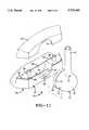
- FIG. 1is a perspective view of the exercise device of the present invention
- FIG. 2is an enlarged top plan view of the exercise device of FIG. 1;
- FIG. 3is a side elevational view of the exercise device of FIG. 2;
- FIG. 4is a perspective view similar to FIG. 1 of a modified embodiment of the exercise device shown in FIGS. 1-3;
- FIG. 5is a rear perspective view of the pivot ball removed from the device, as shown in FIGS. 1-3;
- FIG. 6is a front perspective view of the pivot ball of FIG. 5;
- FIG. 7is an enlarged fragmentary sectional view taken on line 7--7, FIG. 2;
- FIG. 8is a fragmentary exploded perspective view of the platform and ball/socket pivot components of FIG. 1;
- FIGS. 9 and 10are diagrammatic side elevational views showing the manner of use of the exercise device of the present invention.
- FIG. 11is a fragmentary exploded view showing a modified pivotal mounting arrangement of the pivot ball and receiving socket
- FIG. 12is a sectional view showing the mounting of the pivot ball within the socket of FIG. 11;
- FIG. 13is an enlarged fragmentary sectional view showing the slidable connection between the components of the body cage portion of the device shown particularly in FIGS. 1-4.
- the exercise device of the present inventionis indicated generally at 1, and is shown in FIGS. 1-3 in an assembled operable position.
- Device 1includes a platform, indicated generally at 2, and a body cage, indicated generally at 3, which is pivotally connected to platform 2 by a pair of pivot mechanisms 4.
- Platform 2is adapted to be placed in a fixed position on a flat support surface 6, as shown in FIGS. 9 and 10, and is intended to support the lower torso of a user.
- Platform 2includes a flat bottom 5 which contacts and supports the device on support surface 6, and further includes a pair of opposed parallel side walls 7, and an upper intervening support surface 8.
- Support surface 8is substantially flat and may have a shallow concave central portion 9 which extends slightly inwardly from side walls 7 so as to conform generally with the curvature of the lower back of the user.
- Each side wall 7preferably includes a substantially flat vertically extending inner wall 13 and a partial outer wall 17, which walls form a hollow interior 14 (FIG. 8).
- Outer wall 17is formed with a semicircular recess 15 and a pair of upwardly curved edges 16.
- An upper wall portion, indicated generally at 18,is formed with a semicircular concave recess 19 and a plurality of snap-fit projections 20 which engage complementary-shaped recesses or projections (not shown) formed within the hollow interior of side walls 7 for securing upper wall portions 18 in position on side walls 7.
- Upper wall portions 18are formed with curved bottom edges 18a which are complementary to the curvature of edges 16 of walls 7 so as to mate therewith when wall portions 18 are joined with walls 7.
- Pivot mechanism 4includes a circular socket 21 formed in side wall 7 by aligned recesses 15 and 19, and a pivot ball, indicated generally at 23 and shown in FIGS. 5 and 6.
- Pivot ball 23includes an outer semispherical portion 24 and an inner cylindrical portion 25, which portions form an integral one-piece member formed of a rigid plastic material.
- a through hole 26(FIG. 7) is formed in pivot ball 23 and receives a fastening pin 27 therein.
- Hole 26preferably has a countersunk outer end 28.
- Pin 27extends into a blind hole 29 formed in wall 7 and secures pivot ball 23 within circular socket 21 in each of the platform side walls 7. If desired, pin 27 could extend completely through wall 7 and be secured by another type of fastener to side wall 7.
- cylindrical inner portion 25 of each pivot ball 23is freely rotatable within a respective circular socket 21 to provide for the pivotal movement of cage 3, as discussed further below.
- Cage 3preferably is formed of a thin-wall lightweight aluminum or stainless steel tubing and includes a U-shaped head and neck portion, indicated generally at 30, and a pair of inclined connecting members 31.
- U-shaped support portion 30includes a central section 33 and a pair of legs 34, each leg having an inclined section 35 and a linearly extending section 36 (FIG. 3).
- a padded cushion 37preferably is mounted on central portion 33 to provide a comfortable support and rest for the head of a user, as shown in FIGS. 9 and 10.
- Each of the inclined connecting members 31includes a generally vertically extending section 39 and a linear, generally horizontally extending section 40, which form a substantially smooth curved right-angled corner 41 with section 39.
- the lower ends of inclined connecting members 31are slidably received within a blind hole 43 (FIG. 7) formed in semispherical outer portion 24 of pivot ball 23, and are secured therein by pins 27 which extend through holes 43a formed in the free ends of connecting members 31.
- U-shaped head and neck support portion 30is adjustably mounted on connecting members 31 to permit the distance between support cushion 37 and platform 2 to be adjusted to match the particular size of an exerciser using device 1.
- One type of adjustmentmay be a pair of spring-biased detents 44 which are mounted on the end of a leaf spring (not shown) which is located in the outer end of each of the connecting members 31. Detents 44 are selectively received within selected ones of a plurality of holes 45 formed in the extended free ends of legs 34 of U-shaped support members 30.
- the spring-biased detentsare merely one type of adjustment mechanism which can be utilized to adjust the size of body cage 3 for accommodating exercisers of various body sizes.
- FIG. 4shows a modified type of adjusting mechanism, which is indicated generally at 50.
- Adjustment 50includes a pair of tubular members 46, the outer ends of which are slidably received within the open ends of connecting members 31 and U-shaped head and neck support member 30.
- An adjustable pivot mechanism 48is mounted between the inner ends of tubular members 46 for placing the members in a predetermined angular position where they are secured by a locking knob 49 once set by the particular exerciser.
- Other types of adjusting mechanismsthan the spring-biased detents of FIGS. 1-3 and the adjustable pivot mechanism of FIG. 4 can be utilized.
- FIGS. 9 and 10show one manner in which device 1 can be utilized for performing a sit-up type of abdominal exercise, and its manner of use and the advantages achieved thereby are described below.
- exercise device 1 of the present inventiongenerally comprises upper body cage 3 which is pivotally mounted on substantially flat stable platform 2. More specifically, upper body cage 3 comprises left and right inclined upper sections 35 and linear sections 36 which are slidingly or rotatably connected to sections 40 of left and right lower connecting members 31. Members 31 include substantially vertically oriented sections 39 which pivotally connected to left and right lateral walls 7 of platform 2. The left and right inclined upper sections 35 of the upper body cage are connected proximally to form the substantially U-shaped neck support portion 30 having padded cushion 37 for comfortably supporting the weight of the user's head and neck.
- the left and right linear upper sections 36are slidingly or rotatably connected to the left and right linear sections 40 so as to permit the device to be ideally positioned under the user to thereby accurately position the neck support and the stable platform specific to the body dimensions of the individual user and thus ensure a full range of motion of the exercise in an ideal plane of movement so as to maximally recruit the abdominal muscles.
- the linear inclined sections 35 of the device of the present inventionfurther provide a plurality of hand grasp positions whereby the user grasping the hands at the maximum inclination of linear sections 35 adjacent sections 36 of the upper portion of body cage 3, effectively reduces the user's mechanical advantage for lifting the body into the exercise range of motion. Conversely, grasping the sections 35 at the lowest point of inclination adjacent central portion 33, increases the user's mechanical advantage for lifting the body into the sit-up exercise range of motion.
- the usermay, by varying the hand position along the length provided by the sections 35 of the upper body cage, progressively increase or decrease the resistance to the exercise.
- a mechanical lift advantageis provided by the user's arm strength so as to assist the abdominal muscles in performance of the exercise.
- the potential for the user recruiting arm muscle strength to assist in the liftis reduced, thus focusing the lift demand to the abdominal musculature.
- the neck support provided by portion 33 and cushion 37effectively reduces stress to the anterior musculature of the neck.
- the sit-up exerciseis performed with the user's hands clasped behind the neck to therefore prevent hyperextension of the neck and thus impingement of the sensitive cervical spine facet joints.
- the neckWith the hands clasped behind the user's neck, there is a tendency for the neck to be hyperflexed by the pulling forces of the user's arms. Hyperflexion of the neck increases loading on the cervical spine discs, predisposing the discs to excessive compression strain and thereby increasing the potential for disc rupture and herniation.
- hyperflexion of the neckplaces a long axis traction stress to the posterior cervical musculature and may result in muscular strain or sprain.
- Upper body cage 3extends from the neck support portion to the pivoting attachment at stable platform 2.
- the platformis ideally positioned under the user's body so as to locate the pivoting point of the upper cage assembly directly under the user's spine at the thoraco-lumbar junction.
- the thoraco-lumbar junctionis defined as that area of the spine where the rib cage ends and the lumbar spine begins.
- the rigid upper cage and the placement of the pivot point at the thoraco-lumbar junctionpermits improved isolation of the abdominal musculature, ensures the movement is performed in the proper plane to effectively and maximally recruit the abdominal musculature during the exercise and eliminates the potential for cheating, restricting the recruitment of accessory muscle groups and eliminating the potential for the user to use momentum to overcome the inertia required to initiate the exercise movement.
- the upper cage assemblyinclude a means for selectively varying the distance between the neck support means and the pivot point.
- the upper cageincludes an adjustment means to permit the selective adjustment and alignment of the neck support means and the pivot point specific to the user's anatomical requirement. This angle adjustment between the upper portion and lower portion of cage 3 permits the individual user to better isolate the abdominal musculature through fixation of the upper torso above the thoraco-lumbar junction of the spine, thus fixing the fulcrum of the movement at one attachment of the abdominal musculature.
- the ball and socket pivot meanspermits a full and free range of motion of the sit-up exercise.
- the usersimply twists the lower limbs, knees and hips bent to approximately 90 degrees, to the left side of the body to thereby orient the right internal oblique and left external oblique muscles in the proper exercise plane. Twisting the lower limbs to the right side of the body, knees and hips bent to approximately 90 degrees orients the left internal oblique and right external oblique muscles in the proper exercise plane.
- oblique crunchesIn addition to the usual abdominal sit-up exercises above, referred to as the abdominal crunch, oblique crunches also can be performed by the user bending the knees approximately 90 degrees and twisting to either the left or right side. Also, knee-up exercises can be performed, wherein the exerciser lies supine with hips and knees bent approximately 90 degrees and grasps along sections 35 of cage 3 and lifts the knees up and towards the torso.
- FIGS. 11-12show a pivot connection modified from that shown particularly in FIG. 7.
- the pivotal connection of FIGS. 11 and 12, which is indicated generally at 70,includes a pivot ball, indicated generally at 71, having a semispherical portion 72 which merges into a cylindrical portion 73 which terminates in an enlarged cylindrical end portion 74 which is connected to cylindrical portion 73 by a stepped shoulder 75.
- An opening 77is formed in portion 72 for receiving free end 78 of body cage connecting member 31 therein, where it is secured by a threaded fastener 79.
- Modified side wall 80 of platform 2includes a generally trapezoidal-shaped lower wall portion or base 81 having a pair of cylindrical bosses 82 for securing an upper wall portion 83 thereon by a pair of bolts (not shown) which extend through bosses 82 and into threaded holes formed in upper wall portion 83.
- a plurality of nubs 84are formed on a top wall 85 of lower wall portion 81, which are received within upper wall portion 83 to assist in stabilizing the two members in a secured position (FIG. 12).
- a pair of semicircular inner and outer concave recesses 88 and 89are formed in wall portion 81 and are separated by an upstanding wall 87, with the enlarged annular end 74 of ball 71 being rotatably mounted within outer recess 89 when top wall portion 83 is secured to bottom wall portion 81, as shown in FIG. 12.
- outer concave recess 89provides a smooth surface on which cylindrical end portion 74 of ball 71 slidably rotates and pivots when the body cage portion is being pivotally moved when performing an exercise.
- FIG. 13shows the use of an elastomeric sleeve 98 being mounted on the end of each of the connecting members 31 when they are slidably received within the respective hollow interior of legs 34, such as shown in FIGS. 1-3, to form a more stable connection therebetween, which is free of vibration.
Landscapes
- Health & Medical Sciences (AREA)
- Engineering & Computer Science (AREA)
- Biomedical Technology (AREA)
- Neurology (AREA)
- Orthopedic Medicine & Surgery (AREA)
- Pulmonology (AREA)
- General Health & Medical Sciences (AREA)
- Physical Education & Sports Medicine (AREA)
- Rehabilitation Tools (AREA)
Abstract
Description
Claims (15)
Priority Applications (1)
| Application Number | Priority Date | Filing Date | Title |
|---|---|---|---|
| US08/664,222US5725463A (en) | 1995-07-14 | 1996-06-11 | Abdominal exercise device |
Applications Claiming Priority (2)
| Application Number | Priority Date | Filing Date | Title |
|---|---|---|---|
| US117595P | 1995-07-14 | 1995-07-14 | |
| US08/664,222US5725463A (en) | 1995-07-14 | 1996-06-11 | Abdominal exercise device |
Publications (1)
| Publication Number | Publication Date |
|---|---|
| US5725463Atrue US5725463A (en) | 1998-03-10 |
Family
ID=26668676
Family Applications (1)
| Application Number | Title | Priority Date | Filing Date |
|---|---|---|---|
| US08/664,222Expired - Fee RelatedUS5725463A (en) | 1995-07-14 | 1996-06-11 | Abdominal exercise device |
Country Status (1)
| Country | Link |
|---|---|
| US (1) | US5725463A (en) |
Cited By (44)
| Publication number | Priority date | Publication date | Assignee | Title |
|---|---|---|---|---|
| US5813957A (en)* | 1997-04-24 | 1998-09-29 | Rossiter; Frank E. | Aquatic abdominal exerciser apparatus |
| US6027434A (en)* | 1998-11-16 | 2000-02-22 | Gibbons; Thomas J. | Device for relieving leg cramps |
| US6213923B1 (en) | 1999-03-30 | 2001-04-10 | Cape Hatteras Management Limited | Back exercise device |
| US6582347B2 (en) | 2000-12-27 | 2003-06-24 | Fitness Quest Inc. | Abdominal exercise device and methods of use |
| US20040106883A1 (en)* | 2002-12-03 | 2004-06-03 | Pidcock Ralph M. | Method and apparatus for relieving leg cramps and massaging muscles |
| US20050250629A1 (en)* | 2004-05-10 | 2005-11-10 | Webb Nicholas J | Inflatable abdominal exercise apparatus |
| US20050250630A1 (en)* | 2004-05-10 | 2005-11-10 | Webb Nicholas J | Inflatable abdominal exercise apparatus |
| USD516638S1 (en) | 2003-10-24 | 2006-03-07 | Goodmarc Designs Ltd. | Exercise device |
| USD524385S1 (en) | 2004-10-12 | 2006-07-04 | Turbo Fitness Products Llc | Inflatable exercise apparatus |
| US20060229169A1 (en)* | 2005-04-12 | 2006-10-12 | Stephen Falter | Training Hoop |
| US7172539B1 (en) | 2004-01-02 | 2007-02-06 | Alice Bythewood | Abdominal exercising support apparatus |
| US20070099778A1 (en)* | 2005-10-27 | 2007-05-03 | Ming-Jen Ko | Twister and sit-up combination exerciser |
| US20070281840A1 (en)* | 2006-06-02 | 2007-12-06 | Mao-Bang Tsai | Sit-up exercise machine |
| US7329213B1 (en) | 2004-03-25 | 2008-02-12 | Farley Michael D | Exercise machine with compound abdominal movement |
| USD574901S1 (en)* | 2007-05-23 | 2008-08-12 | Engineering Fitness International Corp. | Abdominal exercise apparatus |
| RU2336921C2 (en)* | 2006-11-28 | 2008-10-27 | Михаил Иосифович Шендерович | Device for development of backbone muscles |
| US20090001703A1 (en)* | 2005-04-12 | 2009-01-01 | Stephen Falter | Training Hoop |
| USD608401S1 (en) | 2009-03-06 | 2010-01-19 | Total Gym Fitness, Llc | Abdominal exercise apparatus |
| USD612000S1 (en) | 2009-03-06 | 2010-03-16 | Total Gym Fitness, Llc | Abdominal exercise apparatus |
| US20100227748A1 (en)* | 2009-03-06 | 2010-09-09 | Total Gym Fitness, Llc | Inclinable exercise device with abdominal crunch exercise accessory apparatus and method |
| USD625372S1 (en)* | 2009-10-29 | 2010-10-12 | Cybex International, Inc. | Handle |
| US20100311555A1 (en)* | 2004-02-24 | 2010-12-09 | Engineering Fitness International Corp. | Inclinable Exercise Device With Abdominal Crunch Board and Method |
| US20110301002A1 (en)* | 2010-06-08 | 2011-12-08 | Scott Sebastian | Abdominal exercise and training apparatus |
| US8262593B2 (en) | 2002-12-03 | 2012-09-11 | Pidcock Ralph M | Method and apparatus for relieving leg cramps and massaging muscles |
| USD727441S1 (en)* | 2013-06-28 | 2015-04-21 | Jin-Chen Chuang | Exercise device for situp |
| USD736865S1 (en) | 2014-12-09 | 2015-08-18 | Dean Erickson | Star shaped exercise platform |
| US20160129303A1 (en)* | 2014-11-06 | 2016-05-12 | Susan Fullerton | Ab Crunch Neck Support |
| USD790011S1 (en)* | 2015-05-15 | 2017-06-20 | Xiamen Zhoulong Sporting Goods Co., Ltd. | Exercise platform with two arms |
| USD791888S1 (en)* | 2016-02-21 | 2017-07-11 | Chi-Wei Huang | Exercise platform with two arms |
| USD818548S1 (en)* | 2015-08-24 | 2018-05-22 | Wei-Teh Ho | Abdominal exerciser |
| US10188890B2 (en) | 2013-12-26 | 2019-01-29 | Icon Health & Fitness, Inc. | Magnetic resistance mechanism in a cable machine |
| US10252109B2 (en) | 2016-05-13 | 2019-04-09 | Icon Health & Fitness, Inc. | Weight platform treadmill |
| WO2019075313A1 (en)* | 2017-10-13 | 2019-04-18 | Domesick Michael Harris | Plank support exercise apparatus and related methods |
| US10279212B2 (en) | 2013-03-14 | 2019-05-07 | Icon Health & Fitness, Inc. | Strength training apparatus with flywheel and related methods |
| US10293211B2 (en) | 2016-03-18 | 2019-05-21 | Icon Health & Fitness, Inc. | Coordinated weight selection |
| US10426989B2 (en) | 2014-06-09 | 2019-10-01 | Icon Health & Fitness, Inc. | Cable system incorporated into a treadmill |
| US10441840B2 (en) | 2016-03-18 | 2019-10-15 | Icon Health & Fitness, Inc. | Collapsible strength exercise machine |
| US10449416B2 (en) | 2015-08-26 | 2019-10-22 | Icon Health & Fitness, Inc. | Strength exercise mechanisms |
| US10661114B2 (en) | 2016-11-01 | 2020-05-26 | Icon Health & Fitness, Inc. | Body weight lift mechanism on treadmill |
| US10940360B2 (en) | 2015-08-26 | 2021-03-09 | Icon Health & Fitness, Inc. | Strength exercise mechanisms |
| US11571604B2 (en) | 2020-03-11 | 2023-02-07 | Mohammed Hassan Aref | Abdominal exercise device |
| USD979672S1 (en)* | 2017-10-18 | 2023-02-28 | Bootysprout, Inc. | Exercise system |
| USD998067S1 (en)* | 2019-08-07 | 2023-09-05 | Tengfei Zhang | Exercising apparatus |
| US12161910B2 (en) | 2020-03-11 | 2024-12-10 | Mohammed Hassan Aref | Abdominal exercise device |
Citations (35)
| Publication number | Priority date | Publication date | Assignee | Title |
|---|---|---|---|---|
| US1244371A (en)* | 1917-05-19 | 1917-10-23 | Charles H Reynolds | Rocking toy. |
| US1911572A (en)* | 1933-05-30 | Rocking device | ||
| US2429939A (en)* | 1945-11-03 | 1947-10-28 | Masterson Norma Bigler | Convertible and demountable gymnastic chair |
| US2446275A (en)* | 1946-06-07 | 1948-08-03 | John A Glasin | Oscillating tilt drop adjusting table |
| US2475289A (en)* | 1948-01-17 | 1949-07-05 | Richard Hudnut | Rocking device |
| US2563407A (en)* | 1951-08-07 | Rocker toy | ||
| US2722967A (en)* | 1952-07-01 | 1955-11-08 | William H Reinholz | Rocking chair |
| DE1903502A1 (en)* | 1969-01-24 | 1970-08-13 | Villinger Dipl Ing Franz | Gymnastics device |
| US3591173A (en)* | 1970-01-12 | 1971-07-06 | Eli Joseph Cossman | Head stand support |
| FR2239262A1 (en)* | 1973-08-03 | 1975-02-28 | Gaubert Louis | Mechanism for exercising abdominal muscles - has lever emanating from variable friction ball and socket joint |
| US4183520A (en)* | 1978-03-09 | 1980-01-15 | Chase Daniel F | Exercising device having operably interconnected primary and secondary pivot arms |
| US4241949A (en)* | 1978-09-20 | 1980-12-30 | Parker Michael S | Rockable furniture |
| US4307880A (en)* | 1977-11-15 | 1981-12-29 | Abram Gin Y | Device for yoga exercising |
| US4314697A (en)* | 1980-02-19 | 1982-02-09 | Brumfield Maxine L | Physical exercising device |
| US4367870A (en)* | 1980-04-25 | 1983-01-11 | Birch Robert A | Shoulder stand device |
| US4405128A (en)* | 1980-12-11 | 1983-09-20 | Totem, Inc. | Muscular exercise apparatus and method |
| US4489936A (en)* | 1982-01-08 | 1984-12-25 | Antonio Dal Monte | Gymnastic implement |
| US4582319A (en)* | 1984-05-07 | 1986-04-15 | Luna Mario A | Sit-up exercise bench |
| US4729562A (en)* | 1986-10-22 | 1988-03-08 | George Pipasik | Total abdominal workout machine |
| US4752067A (en)* | 1986-07-08 | 1988-06-21 | Colonello Dennis J | Apparatus for use in exercising the abdominal muscles |
| US4863158A (en)* | 1988-07-22 | 1989-09-05 | Tassone Daniel R | Sit-up exercise aid |
| US4902003A (en)* | 1985-09-23 | 1990-02-20 | Buoni Nick J | Exercise device and method |
| US5033742A (en)* | 1990-07-12 | 1991-07-23 | Consumer Direct, Inc. | Inflatable sit-up exercise device |
| US5100130A (en)* | 1990-07-18 | 1992-03-31 | Shoebrooks Jeffrey D | Abdominal exercise device |
| US5122107A (en)* | 1991-10-09 | 1992-06-16 | Gardner William G | Situp exercise head-support harness |
| US5125650A (en)* | 1991-04-03 | 1992-06-30 | Paris Erwin W | Flat stomach machine |
| US5215511A (en)* | 1992-05-14 | 1993-06-01 | Cheng Wen Liang | Indoor gymnastic apparatus with means for back massaging |
| US5256126A (en)* | 1992-02-05 | 1993-10-26 | Grote Sport Inc. | Abdominal and back exercising device |
| US5290209A (en)* | 1991-10-04 | 1994-03-01 | Wilkinson William T | Push and pull exercise device |
| US5300005A (en)* | 1993-02-25 | 1994-04-05 | Greenmaster Industrial Corporation | Structure of abdomen exerciser |
| US5346447A (en)* | 1991-11-18 | 1994-09-13 | Stearns Technologies, Inc. | Exercise machine |
| US5393280A (en)* | 1993-07-21 | 1995-02-28 | Haviv; Joseph | Swimming exercise and training apparatus |
| US5441473A (en)* | 1993-11-16 | 1995-08-15 | Safani; Alan K. | Compact back exerciser |
| US5492520A (en)* | 1994-07-07 | 1996-02-20 | Brown; Donald | Abdominal exerciser device |
| US5545114A (en)* | 1995-04-25 | 1996-08-13 | Kor-One, Ltd. | Abdominal exercise device |
- 1996
- 1996-06-11USUS08/664,222patent/US5725463A/ennot_activeExpired - Fee Related
Patent Citations (35)
| Publication number | Priority date | Publication date | Assignee | Title |
|---|---|---|---|---|
| US1911572A (en)* | 1933-05-30 | Rocking device | ||
| US2563407A (en)* | 1951-08-07 | Rocker toy | ||
| US1244371A (en)* | 1917-05-19 | 1917-10-23 | Charles H Reynolds | Rocking toy. |
| US2429939A (en)* | 1945-11-03 | 1947-10-28 | Masterson Norma Bigler | Convertible and demountable gymnastic chair |
| US2446275A (en)* | 1946-06-07 | 1948-08-03 | John A Glasin | Oscillating tilt drop adjusting table |
| US2475289A (en)* | 1948-01-17 | 1949-07-05 | Richard Hudnut | Rocking device |
| US2722967A (en)* | 1952-07-01 | 1955-11-08 | William H Reinholz | Rocking chair |
| DE1903502A1 (en)* | 1969-01-24 | 1970-08-13 | Villinger Dipl Ing Franz | Gymnastics device |
| US3591173A (en)* | 1970-01-12 | 1971-07-06 | Eli Joseph Cossman | Head stand support |
| FR2239262A1 (en)* | 1973-08-03 | 1975-02-28 | Gaubert Louis | Mechanism for exercising abdominal muscles - has lever emanating from variable friction ball and socket joint |
| US4307880A (en)* | 1977-11-15 | 1981-12-29 | Abram Gin Y | Device for yoga exercising |
| US4183520A (en)* | 1978-03-09 | 1980-01-15 | Chase Daniel F | Exercising device having operably interconnected primary and secondary pivot arms |
| US4241949A (en)* | 1978-09-20 | 1980-12-30 | Parker Michael S | Rockable furniture |
| US4314697A (en)* | 1980-02-19 | 1982-02-09 | Brumfield Maxine L | Physical exercising device |
| US4367870A (en)* | 1980-04-25 | 1983-01-11 | Birch Robert A | Shoulder stand device |
| US4405128A (en)* | 1980-12-11 | 1983-09-20 | Totem, Inc. | Muscular exercise apparatus and method |
| US4489936A (en)* | 1982-01-08 | 1984-12-25 | Antonio Dal Monte | Gymnastic implement |
| US4582319A (en)* | 1984-05-07 | 1986-04-15 | Luna Mario A | Sit-up exercise bench |
| US4902003A (en)* | 1985-09-23 | 1990-02-20 | Buoni Nick J | Exercise device and method |
| US4752067A (en)* | 1986-07-08 | 1988-06-21 | Colonello Dennis J | Apparatus for use in exercising the abdominal muscles |
| US4729562A (en)* | 1986-10-22 | 1988-03-08 | George Pipasik | Total abdominal workout machine |
| US4863158A (en)* | 1988-07-22 | 1989-09-05 | Tassone Daniel R | Sit-up exercise aid |
| US5033742A (en)* | 1990-07-12 | 1991-07-23 | Consumer Direct, Inc. | Inflatable sit-up exercise device |
| US5100130A (en)* | 1990-07-18 | 1992-03-31 | Shoebrooks Jeffrey D | Abdominal exercise device |
| US5125650A (en)* | 1991-04-03 | 1992-06-30 | Paris Erwin W | Flat stomach machine |
| US5290209A (en)* | 1991-10-04 | 1994-03-01 | Wilkinson William T | Push and pull exercise device |
| US5122107A (en)* | 1991-10-09 | 1992-06-16 | Gardner William G | Situp exercise head-support harness |
| US5346447A (en)* | 1991-11-18 | 1994-09-13 | Stearns Technologies, Inc. | Exercise machine |
| US5256126A (en)* | 1992-02-05 | 1993-10-26 | Grote Sport Inc. | Abdominal and back exercising device |
| US5215511A (en)* | 1992-05-14 | 1993-06-01 | Cheng Wen Liang | Indoor gymnastic apparatus with means for back massaging |
| US5300005A (en)* | 1993-02-25 | 1994-04-05 | Greenmaster Industrial Corporation | Structure of abdomen exerciser |
| US5393280A (en)* | 1993-07-21 | 1995-02-28 | Haviv; Joseph | Swimming exercise and training apparatus |
| US5441473A (en)* | 1993-11-16 | 1995-08-15 | Safani; Alan K. | Compact back exerciser |
| US5492520A (en)* | 1994-07-07 | 1996-02-20 | Brown; Donald | Abdominal exerciser device |
| US5545114A (en)* | 1995-04-25 | 1996-08-13 | Kor-One, Ltd. | Abdominal exercise device |
Cited By (51)
| Publication number | Priority date | Publication date | Assignee | Title |
|---|---|---|---|---|
| US5813957A (en)* | 1997-04-24 | 1998-09-29 | Rossiter; Frank E. | Aquatic abdominal exerciser apparatus |
| US6027434A (en)* | 1998-11-16 | 2000-02-22 | Gibbons; Thomas J. | Device for relieving leg cramps |
| US6213923B1 (en) | 1999-03-30 | 2001-04-10 | Cape Hatteras Management Limited | Back exercise device |
| US6582347B2 (en) | 2000-12-27 | 2003-06-24 | Fitness Quest Inc. | Abdominal exercise device and methods of use |
| US20040106883A1 (en)* | 2002-12-03 | 2004-06-03 | Pidcock Ralph M. | Method and apparatus for relieving leg cramps and massaging muscles |
| US6966883B2 (en) | 2002-12-03 | 2005-11-22 | Pidcock Ralph M | Method and apparatus for relieving leg cramps and massaging muscles |
| US8262593B2 (en) | 2002-12-03 | 2012-09-11 | Pidcock Ralph M | Method and apparatus for relieving leg cramps and massaging muscles |
| USD516638S1 (en) | 2003-10-24 | 2006-03-07 | Goodmarc Designs Ltd. | Exercise device |
| US7172539B1 (en) | 2004-01-02 | 2007-02-06 | Alice Bythewood | Abdominal exercising support apparatus |
| US20100311555A1 (en)* | 2004-02-24 | 2010-12-09 | Engineering Fitness International Corp. | Inclinable Exercise Device With Abdominal Crunch Board and Method |
| US8075457B2 (en) | 2004-02-24 | 2011-12-13 | Total Gym Global Corp. | Inclinable exercise device with abdominal crunch board and method |
| US7329213B1 (en) | 2004-03-25 | 2008-02-12 | Farley Michael D | Exercise machine with compound abdominal movement |
| US20050250629A1 (en)* | 2004-05-10 | 2005-11-10 | Webb Nicholas J | Inflatable abdominal exercise apparatus |
| US20050250630A1 (en)* | 2004-05-10 | 2005-11-10 | Webb Nicholas J | Inflatable abdominal exercise apparatus |
| USD524385S1 (en) | 2004-10-12 | 2006-07-04 | Turbo Fitness Products Llc | Inflatable exercise apparatus |
| US20090001703A1 (en)* | 2005-04-12 | 2009-01-01 | Stephen Falter | Training Hoop |
| US20060229169A1 (en)* | 2005-04-12 | 2006-10-12 | Stephen Falter | Training Hoop |
| US8113999B2 (en)* | 2005-04-12 | 2012-02-14 | Stephen Falter | Training hoop |
| US7232405B2 (en)* | 2005-10-27 | 2007-06-19 | Ming-Jen Ko | Twister and sit-up combination exerciser |
| US20070099778A1 (en)* | 2005-10-27 | 2007-05-03 | Ming-Jen Ko | Twister and sit-up combination exerciser |
| US20070281840A1 (en)* | 2006-06-02 | 2007-12-06 | Mao-Bang Tsai | Sit-up exercise machine |
| RU2336921C2 (en)* | 2006-11-28 | 2008-10-27 | Михаил Иосифович Шендерович | Device for development of backbone muscles |
| USD574901S1 (en)* | 2007-05-23 | 2008-08-12 | Engineering Fitness International Corp. | Abdominal exercise apparatus |
| US7938763B2 (en) | 2009-03-06 | 2011-05-10 | Engineering Fitness International Corp. | Inclinable exercise device with abdominal crunch exercise accessory apparatus and method |
| US20100227748A1 (en)* | 2009-03-06 | 2010-09-09 | Total Gym Fitness, Llc | Inclinable exercise device with abdominal crunch exercise accessory apparatus and method |
| USD612000S1 (en) | 2009-03-06 | 2010-03-16 | Total Gym Fitness, Llc | Abdominal exercise apparatus |
| USD608401S1 (en) | 2009-03-06 | 2010-01-19 | Total Gym Fitness, Llc | Abdominal exercise apparatus |
| USD625372S1 (en)* | 2009-10-29 | 2010-10-12 | Cybex International, Inc. | Handle |
| US20110301002A1 (en)* | 2010-06-08 | 2011-12-08 | Scott Sebastian | Abdominal exercise and training apparatus |
| US8118720B2 (en)* | 2010-06-08 | 2012-02-21 | Sebastian Scott M | Abdominal exercise and training apparatus |
| US10279212B2 (en) | 2013-03-14 | 2019-05-07 | Icon Health & Fitness, Inc. | Strength training apparatus with flywheel and related methods |
| USD727441S1 (en)* | 2013-06-28 | 2015-04-21 | Jin-Chen Chuang | Exercise device for situp |
| US10188890B2 (en) | 2013-12-26 | 2019-01-29 | Icon Health & Fitness, Inc. | Magnetic resistance mechanism in a cable machine |
| US10426989B2 (en) | 2014-06-09 | 2019-10-01 | Icon Health & Fitness, Inc. | Cable system incorporated into a treadmill |
| US20160129303A1 (en)* | 2014-11-06 | 2016-05-12 | Susan Fullerton | Ab Crunch Neck Support |
| USD736865S1 (en) | 2014-12-09 | 2015-08-18 | Dean Erickson | Star shaped exercise platform |
| USD790011S1 (en)* | 2015-05-15 | 2017-06-20 | Xiamen Zhoulong Sporting Goods Co., Ltd. | Exercise platform with two arms |
| USD818548S1 (en)* | 2015-08-24 | 2018-05-22 | Wei-Teh Ho | Abdominal exerciser |
| US10940360B2 (en) | 2015-08-26 | 2021-03-09 | Icon Health & Fitness, Inc. | Strength exercise mechanisms |
| US10449416B2 (en) | 2015-08-26 | 2019-10-22 | Icon Health & Fitness, Inc. | Strength exercise mechanisms |
| USD791888S1 (en)* | 2016-02-21 | 2017-07-11 | Chi-Wei Huang | Exercise platform with two arms |
| US10293211B2 (en) | 2016-03-18 | 2019-05-21 | Icon Health & Fitness, Inc. | Coordinated weight selection |
| US10441840B2 (en) | 2016-03-18 | 2019-10-15 | Icon Health & Fitness, Inc. | Collapsible strength exercise machine |
| US10252109B2 (en) | 2016-05-13 | 2019-04-09 | Icon Health & Fitness, Inc. | Weight platform treadmill |
| US10661114B2 (en) | 2016-11-01 | 2020-05-26 | Icon Health & Fitness, Inc. | Body weight lift mechanism on treadmill |
| WO2019075313A1 (en)* | 2017-10-13 | 2019-04-18 | Domesick Michael Harris | Plank support exercise apparatus and related methods |
| USD979672S1 (en)* | 2017-10-18 | 2023-02-28 | Bootysprout, Inc. | Exercise system |
| USD1010032S1 (en)* | 2017-10-18 | 2024-01-02 | Bootysprout, Inc | Exercise system |
| USD998067S1 (en)* | 2019-08-07 | 2023-09-05 | Tengfei Zhang | Exercising apparatus |
| US11571604B2 (en) | 2020-03-11 | 2023-02-07 | Mohammed Hassan Aref | Abdominal exercise device |
| US12161910B2 (en) | 2020-03-11 | 2024-12-10 | Mohammed Hassan Aref | Abdominal exercise device |
Similar Documents
| Publication | Publication Date | Title |
|---|---|---|
| US5725463A (en) | Abdominal exercise device | |
| US5256126A (en) | Abdominal and back exercising device | |
| US5779607A (en) | Abdominal exercise machine adapted for strength exercises | |
| US5599261A (en) | Exercise device with two-way articulation | |
| US6213923B1 (en) | Back exercise device | |
| US5871425A (en) | Abdominal exercise device | |
| US5071119A (en) | Abdominal exercise device | |
| US6461284B1 (en) | Spherical back exerciser apparatus | |
| US6110081A (en) | Portable resistance-based exercise apparatus | |
| EP0846017B1 (en) | Isometric arm and leg exerciser | |
| US6939277B2 (en) | Abdominal exercise machine | |
| US8672818B2 (en) | Method and apparatus for improving posture | |
| US5776042A (en) | Abdominal exercise device | |
| US5931768A (en) | Abdominal and lower back exercise apparatus | |
| US7766804B2 (en) | Abdominal exerciser and method | |
| US20010019987A1 (en) | Abdominal exercise device and method | |
| US6048293A (en) | Abdominal exercise apparatus | |
| US20040014570A1 (en) | Exercise bench | |
| US7666123B2 (en) | Upper torso exercise machine | |
| US20030181297A1 (en) | Compact abdominal exercise apparatus | |
| US5368537A (en) | Exercise apparatus | |
| US6024679A (en) | Compact exercise device | |
| US20030092543A1 (en) | Upper torso exercise machine | |
| CN210963751U (en) | A sit-up fitness equipment that fits the waist and back | |
| WO2008106057A2 (en) | Collapsible and storable apparatus for exercising core muscles |
Legal Events
| Date | Code | Title | Description |
|---|---|---|---|
| AS | Assignment | Owner name:FITNESS QUEST INC., OHIO Free format text:ASSIGNMENT OF ASSIGNORS INTEREST;ASSIGNORS:COLONELLO, DENNIS R.;SCHNABEL, ROBERT R. JR.;COLLIS, JOHN R.;REEL/FRAME:008086/0687;SIGNING DATES FROM 19960523 TO 19960530 | |
| AS | Assignment | Owner name:WARNERVISION ENTERTAINMENT INC., CALIFORNIA Free format text:SECURITY INTEREST;ASSIGNOR:FITNESS QUEST INC.;REEL/FRAME:008628/0841 Effective date:19970523 | |
| FEPP | Fee payment procedure | Free format text:PAYOR NUMBER ASSIGNED (ORIGINAL EVENT CODE: ASPN); ENTITY STATUS OF PATENT OWNER: SMALL ENTITY | |
| AS | Assignment | Owner name:HARRIS TRUST AND SAVINGS BANK, ILLINOIS Free format text:PATENT COLLATERAL AGREEMENT;ASSIGNOR:FITNESS QUEST INC.;REEL/FRAME:011641/0816 Effective date:20010326 | |
| FPAY | Fee payment | Year of fee payment:4 | |
| AS | Assignment | Owner name:HARRIS TRUST AND SAVINGS BANK, ILLINOIS Free format text:AMENDED AND RESTATED PATENT COLL. AGR.;ASSIGNOR:FITNESS QUEST INC.;REEL/FRAME:014981/0454 Effective date:20030731 | |
| FPAY | Fee payment | Year of fee payment:8 | |
| AS | Assignment | Owner name:COMERICA BANK, MICHIGAN Free format text:ASSIGNMENT OF ASSIGNORS INTEREST;ASSIGNOR:HARRIS N.A. F/K/A HARRIS TRUST AND SAVINGS BANK;REEL/FRAME:019899/0900 Effective date:20060509 | |
| AS | Assignment | Owner name:COMERICA BANK, A TEXAS BANKING ASSOCIATION, MICHIG Free format text:SECURITY AGREEMENT;ASSIGNOR:FITNESS QUEST INC.;REEL/FRAME:023119/0622 Effective date:20090713 | |
| REMI | Maintenance fee reminder mailed | ||
| LAPS | Lapse for failure to pay maintenance fees | ||
| STCH | Information on status: patent discontinuation | Free format text:PATENT EXPIRED DUE TO NONPAYMENT OF MAINTENANCE FEES UNDER 37 CFR 1.362 | |
| FP | Lapsed due to failure to pay maintenance fee | Effective date:20100310 |