US5725358A - Pressure regulated electric pump - Google Patents
Pressure regulated electric pumpDownload PDFInfo
- Publication number
- US5725358A US5725358AUS08/521,472US52147295AUS5725358AUS 5725358 AUS5725358 AUS 5725358AUS 52147295 AUS52147295 AUS 52147295AUS 5725358 AUS5725358 AUS 5725358A
- Authority
- US
- United States
- Prior art keywords
- pump
- pressure
- roller screw
- speed
- motor
- Prior art date
- Legal status (The legal status is an assumption and is not a legal conclusion. Google has not performed a legal analysis and makes no representation as to the accuracy of the status listed.)
- Expired - Fee Related
Links
Images


Classifications
- F—MECHANICAL ENGINEERING; LIGHTING; HEATING; WEAPONS; BLASTING
- F04—POSITIVE - DISPLACEMENT MACHINES FOR LIQUIDS; PUMPS FOR LIQUIDS OR ELASTIC FLUIDS
- F04B—POSITIVE-DISPLACEMENT MACHINES FOR LIQUIDS; PUMPS
- F04B13/00—Pumps specially modified to deliver fixed or variable measured quantities
- F—MECHANICAL ENGINEERING; LIGHTING; HEATING; WEAPONS; BLASTING
- F04—POSITIVE - DISPLACEMENT MACHINES FOR LIQUIDS; PUMPS FOR LIQUIDS OR ELASTIC FLUIDS
- F04B—POSITIVE-DISPLACEMENT MACHINES FOR LIQUIDS; PUMPS
- F04B2205/00—Fluid parameters
- F04B2205/04—Pressure in the outlet chamber
- F—MECHANICAL ENGINEERING; LIGHTING; HEATING; WEAPONS; BLASTING
- F04—POSITIVE - DISPLACEMENT MACHINES FOR LIQUIDS; PUMPS FOR LIQUIDS OR ELASTIC FLUIDS
- F04B—POSITIVE-DISPLACEMENT MACHINES FOR LIQUIDS; PUMPS
- F04B2205/00—Fluid parameters
- F04B2205/05—Pressure after the pump outlet
- Y—GENERAL TAGGING OF NEW TECHNOLOGICAL DEVELOPMENTS; GENERAL TAGGING OF CROSS-SECTIONAL TECHNOLOGIES SPANNING OVER SEVERAL SECTIONS OF THE IPC; TECHNICAL SUBJECTS COVERED BY FORMER USPC CROSS-REFERENCE ART COLLECTIONS [XRACs] AND DIGESTS
- Y10—TECHNICAL SUBJECTS COVERED BY FORMER USPC
- Y10T—TECHNICAL SUBJECTS COVERED BY FORMER US CLASSIFICATION
- Y10T74/00—Machine element or mechanism
- Y10T74/19—Gearing
- Y10T74/19642—Directly cooperating gears
- Y10T74/19698—Spiral
- Y10T74/19702—Screw and nut
- Y10T74/19744—Rolling element engaging thread
- Y10T74/19781—Non-recirculating rolling elements
- Y10T74/19791—Cylindrical or quasi-cylindrical roller element [e.g., inclined roller, etc.]
- Y10T74/19795—Parallel to shaft
Definitions
- the present inventionrelates to electrically driven pumps in general, and in particular to a pressure regulated electrically driven double acting reciprocating pump.
- a paint circulation systemcustomarily comprises a pump for the paint, motor means for operating the pump, and a paint flow line that extends from an outlet from the pump, past the various coating stations to which paint is to be delivered and back to an inlet to the pump.
- Each coating stationis connected to the paint flow line for receiving paint upon demand by coating application equipment at the station, with any paint not provided to a coating station being circulated through the paint flow line and returned to the pump inlet, whereby paint not delivered to a coating station is circulated and maintained in motion so that pigments and fillers in the paint remain in suspension.
- a goal of paint circulation systemsis therefore to provide paint at a constant pressure to the painting equipment, irrespective of the flow rate of paint demanded from the pump.
- the flow demand that the pump must meethas an absolute minimum that is based upon the minimum flow velocity required to keep paint pigments and fillers in suspension. As coating or paint stations go “on” or “off” the flow demand rises and falls at levels above the absolute minimum. Changes in flow demand tend to result in changes in pump outlet pressure.
- turbine pumpsTwo types of supply pumps commonly used in paint circulating systems are turbine pumps which are kinetic pumps and reciprocating pumps which are positive displacement pumps.
- An advantage of a turbine pumpis that it has a very flat pressure response over a wide range of flow rates, which enables the pump to provide a generally constant pressure paint flow under changing flow demands. This is particularly useful in painting systems where flow characteristics are pressure dependent, but there are two significant disadvantages of turbine pumps.
- Positive displacement double acting reciprocating pumpsutilize a piston to pump paint, and as compared to turbine pumps have the advantage of being nonaggressive to and causing minimal degradation to pigments and fillers in the paint, and of being able to attain higher operating efficiencies.
- a reciprocating pumpdoes not run at full speed all the time.
- Reciprocating pumpsare driven by sources that operate under the principal of balancing forces caused by the driving pressure and the driven pressure, so they run at a minimum speed when all coating stations are "off" and speed up only as flow demands increase.
- Reciprocating pumpsnormally have relatively high efficiencies in the 85% to 90% range, but they can be and customarily are driven by reciprocating air or hydraulic mechanisms that have relatively low efficiencies on the order of about 20% and 60%, respectively.
- crank and connecting rod or a cam and cam followerhave been utilized to convert the rotary output of the motor to the reciprocating motion of the pump.
- the efforthas brought with it its own unique disadvantages, since both crank and connecting rod, and cam and cam follower, converting mechanisms result in a serious problem in maintaining a constant pump outlet pressure at changeover of the pump, i.e., during the time when the direction of reciprocation of the pump is reversed.
- both types of converting devicesresult in a rapidly decreasing load torque on the electric motor that allows the motor to rapidly speed up to account for the decreasing reciprocating velocity of the pump relative to the somewhat constant rotational speed of the motor.
- the checks or check valvesthat control entry and exit of liquid to the pump reverse position, which has the effect of "catching" the rapidly rotating motor and severe shocks can result.
- the decreased load torqueabruptly changes to rapidly increasing load torque that causes the electric motor to rapidly slow down.
- the net effectis a situation with difficult to control pressure drops and pressure spikes that respectively occur just before and just after changeover.
- An object of the inventionis to provide a pressure regulated electrically driven positive displacement double acting reciprocating pump that is particularly adapted for use with a paint circulation system.
- Another objectis to provide such an electric pump that provides a substantially constant outlet pressure even at changeover of the pump.
- a further objectis to provide such an electric pump that utilizes a planetary roller screw to convert a rotary output from the electric motor to a reciprocating drive for the pump.
- Yet another objectis to provide such an electric pump in which pump outlet pressure is sensed and the speed of operation of the electric motor is controlled in accordance with the sensed pressure to maintain a substantially constant pump outlet pressure.
- a pressure regulated electric pumpfor delivering at least a minimum volume flow rate of pumped liquid.
- the electric pumpcomprises a positive displacement double acting reciprocating pump having an outlet for delivering pumped liquid and an inlet for connection to a supply of liquid, means for sensing the pressure of pumped liquid, and an electric motor having a rotary output.
- a planetary roller screw assemblyis coupled between the electric motor and the pump for converting the rotary output of the motor to a reciprocating output that operates the pump through pumping strokes and a controller means, that is responsive to the pressure sensing means, controls the direction and speed of rotation of the motor rotary output to operate the pump through pumping strokes at rates controlled to maintain a substantially constant pressure of pumped liquid despite changes in the volume flow rate of pumped liquid.
- the electric motorcomprises an electric servomotor and the planetary roller screw assembly comprises a roller screw coupled to the motor rotary output for rotation in a direction and at a speed of rotation in accordance with the direction and speed of rotation of the motor rotary output, and a roller screw nut coupled to the pump and that is reciprocated by and along the roller screw in a direction and at a speed in accordance with the direction and speed of rotation of the roller screw, to conjointly reciprocate the pump through pumping strokes.
- the pumphas a piston and a piston rod, and the roller screw nut is coupled to the pump piston rod for reciprocating the piston rod and piston through pumping strokes.
- FIG. 1is a front elevation view of a pressure regulated electric pump embodying the teachings of the invention
- FIG. 1ais a cross sectional front elevation view of the upper portion of the pump, illustrating a bearing assembly and a planetary roller screw that are coupled between a rotary output from an electric motor and a piston rod of the pump for converting the rotary output from the motor to reciprocating motion for operating the pump;
- FIG. 2is a side elevation view of the electric pump
- FIG. 3is a rear elevation view of the electric pump
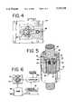
- FIG. 4is a top plan view of the electric pump
- FIG. 5is a perspective view, partially in cross section, of a planetary roller screw that may be used with the electric pump, and
- FIG. 6is a simplified block diagram representation of the pressure regulated electric pump system.
- the present inventionuniquely couples the rotary output from an electric servomotor to a positive displacement double acting reciprocating pump through a planetary roller screw.
- Thisadvantageously combines the high efficiencies of each of a reciprocating pump, an electric servomotor and a planetary roller screw to achieve a high system efficiency, while at the same time avoiding the disadvantages of rapid degradation of the pumped fluid as encountered with turbine pumps, problems associated with freezing in air drive systems, and the potential for fluid contamination in hydraulic drive systems.
- a pressure regulated electric pumpaccording to the teachings of the invention is supported on a platform that includes a bottom plate 20, a top plate 22, a plurality of legs 24 extending between the bottom and top plates and a plurality of supports 26 extending between the legs.
- the pumping mechanismconsists of a positive displacement double acting reciprocating pump assembly, indicated generally at 28, carried by and toward a lower end of the platform.
- the pump assemblyincludes a pump body 30 within which a pump cylinder and a pump piston (neither shown) define pumping chambers to opposite sides of the piston in a manner understood by those skilled in the art.
- An inlet manifold assembly 32 at a lower end of the pump bodyhas an inlet 34 and an outlet manifold assembly 36 at an upper end of the pump body has an outlet 38.
- Appropriate checks or check valvesare provided in the inlet and outlet manifold assemblies, so that with each reciprocation of the pump piston in either direction a pumping stroke is executed.
- the pump pistonis connected to and reciprocated by a pump piston rod 40.
- Means for operating the reciprocating pump assembly 28includes a carriage assembly, indicated generally at 44, coupled to an upper end of the pump piston rod 40 to reciprocate the piston rod and thereby the pump piston.
- the carriage assemblyincludes a planetary roller screw assembly indicated generally at 46 and a bearing assembly indicated generally at 48. The planetary roller screw assembly and the bearing assembly are supported by the top plate 22.
- FIGS. 1a and 5best show the planetary roller screw assembly 46, which includes a roller screw 50 that has a triangular thread with an included angle of 90°.
- a roller screw nut 52is threaded internally with the same type and number of threads as is the roller screw 50.
- a plurality of rollers 54threaded with a single start triangular thread having an included angle of 90°, roll between the roller screw nut and the roller screw.
- the thread formis barrelled to give a large contact radius for high load carrying capacity and high rigidity.
- the helix angle of the thread of the rollers 54is identical to the thread of the roller screw nut 52, so that the rollers do not move axially as they roll inside the roller screw nut.
- Spigots 56 at opposite ends of each roller 54are received in associated openings spaced around and through guide rings 58 (only one shown) at opposite ends of the roller screw nut 52 and keep the rollers equally spaced around the periphery of the roller screw nut.
- the guide rings 58each of which is kept in position by an associated spring ring 60, are not loaded.
- opposite ends of each rollerdefine gear teeth 62 that mesh at each end with an associated internally toothed ring 64 (only one shown).
- a wiper 66is at each end of the planetary roller screw.
- the planetary roller screw assembly 46 as shown in FIG. 5is known in the art and sold by SKF Group as model no. SR/TR/PR.
- a planetary roller screwconsists, in general, of a roller screw and a roller screw nut that moves back and forth along on the roller screw, depending upon the direction in which the roller screw is rotated.
- the deviceis somewhat similar to a ball screw (not shown) only in the sense that, in general, it includes a screw rod and a nut device.
- a ball screwconsists of a screw rod with balls that run in the grooves of the screw rod while recirculating within a nut. Each ball has a point of contact within the groove of the screw rod.
- the balls rolling within the nutare similar to the balls in a bearing, and acceleration is limited to about 0.3 G due to slippage of the balls that occurs at higher accelerations and that causes galling of the grooves in the screw rod.
- a ball screw devicedoes not have a problem of exhibiting a changing torque load at any point of the pump piston stroke due to the relative reciprocating motion of the pump to the rotating motion of the motor, since the load torque on the motor is directly proportional to pressure and any frictional loses in the pump and drive mechanism.
- the planetary roller screw 46has the set of rollers 54 that have the same pitch thread as does the roller screw, and axes that are parallel to the axis of the roller screw.
- Each rollerhas a line of contact with the groove in the roller screw, which allows for much greater loads for a given roller screw diameter than could be accommodated by a ball screw, thereby giving the planetary roller screw a much reduced mass and inertia, as compared to a ball screw, for a specified load rating.
- the rollers of the planetary roller screwalso are linked to a planetary gear that forces their rolling within the roller screw nut 52 to eliminate or nearly eliminate the chance for slippage and galling. Accelerations up to 3.0 G can therefore be realized with a planetary roller screw.
- the carriage assembly 44is connected to the piston rod 40 of the reciprocating pump assembly 28 to reciprocate the piston rod and thereby the pump piston, and includes the planetary roller screw nut 52 of the planetary roller screw assembly 46, a plurality of cam followers 68, a heatsink/oil bath contained within a lower end cover 70, a plurality of struts 72 connecting the roller screw nut 52 to a carriage plate 74, and a pump rod mounting swivel 76 that couples the carriage plate to the upper end of the pump piston rod.
- the roller screw nut 52 of the planetary roller screw assembly 46moves vertically with rotation of the roller screw 50, although the roller screw nut is restricted from rotating by means of the cam followers 68 that are coupled to the roller screw nut and trap stationary runners 78 and 80 between them.
- the bearing assembly 48through which the roller screw 50 extends, includes bearing spacers comprising an outer race 82 and an inner race 84, along with quadrature angular contact bearings 86.
- the inner and outer races 82 and 84 and the quadrature bearings 86are in a bearing housing 88 that mounts to the platform top plate 22.
- the planetary roller screw assemblyis retained in the bearing housing 88 by clamping the outer races of the quadrature bearings within the bearing housing by means of an outer race nut 90.
- the stationary runners 78 and 80, between which the cam followers 68 are received,mount to the bearing housing 88.
- a synchronous drive sprocket or roller screw pulley 92is attached to the upper end of the roller screw 50.
- An electric servomotor 94is connected to the top plate by means of a motor heatsink 96.
- a synchronous drive sprocket or motor pulley 98is attached to an output shaft 100 of the motor.
- the motor pulley 98 and the roller screw pulley 92are connected by a synchronous drive belt 102.
- An upper limit switch 104 and a lower limit switch 106are carried by the stationary runner 80 and are used, as will be described, by a control program upon every start up of the pump assembly.
- the output from the motoris coupled via the motor pulley 98, the synchronous drive belt 102 and the roller screw pulley 92 to the roller screw 50 to rotate the roller screw in the one direction and thereby move or reciprocate the roller screw nut 52 in a first direction along the roller screw to cause the pump piston rod 40, and thereby the pump piston, to reciprocate in the first direction at a speed in accordance with the speed of operation of the motor.
- the roller screw nut and thereby the pump piston rod and the pump pistonare reciprocated in a second and opposite direction at a speed in accordance with the speed of operation of the motor.
- the pressure regulated electric pump of the inventionincludes the pressure transducer 42, which is responsive to or senses the liquid pressure developed by the pump 28 at its outlet and provides a signal representative of the pressure to a controller 108.
- the controllerincludes a CPU or microprocessor that performs a control program and is responsive to the signal from the pressure transducer to control the speed of the motor 94 in a manner to maintain a substantially constant operator selected pressure at the outlet from the pump.
- the electric motor 94At a constant flow demand or flow rate of liquid from the pump, the electric motor 94 generally runs at a constant speed during each stroke of the pump. As flow demand rises and falls, the instantaneous pressure at the pump outlet falls and rises.
- the changing pressureis sensed by the pressure transducer 42, the signal from which is monitored by the controller.
- the controllerthen operates the motor, in accordance with the control program, in a manner to make incremental changes in the speed of operation of the motor to cause the motor to speed up during a pressure fall and to slow down during a pressure rise. So that the response time of the system will be sufficiently fast to make seemingly instantaneous responses to small pressure changes, to thereby maintain a substantially constant pressure at the pump outlet, the control program advantageously cycles through a pressure sampling loop in 300 ms or less.
- the control programinitializes itself by starting the electric motor 94 at a relatively slow speed.
- the control programsamples or senses pump outlet pressure, as indicated by the signal from the transducer 42 at the slow motor speed. If the sensed pressure is less than a setpoint pressure as determined and set by an operator, then the controller incrementally speeds up the motor until the sensed and setpoint pressures are equal, and the pressure equalizing motor speed is set as a setpoint speed.
- the set speedis then fed into a main control loop that samples pump outlet pressure within the 300 ms sampling loop limit. As long as the sampled pump outlet pressure is the same as the setpoint pressure, the commanded speed of the motor is set equal to the setpoint speed.
- new commanded motor speedsare calculated by adding a factor to the setpoint speed.
- the factoris calculated by subtracting the sampled pump outlet pressure from the setpoint pressure and multiplying the difference by a gain. If the sampled pressure is outside of the setable bandwidth, the control loop goes to another control loop that resets the setpoint motor speed in the manner described and then returns to the main control loop.
- the control programfirst operates the motor slowly, until the carriage assembly rises high enough to trip the upper limit switch 104, whereupon the direction of operation of the motor is reversed until the lower limit switch 106 is tripped.
- the control programthen calculates the distance of travel of the roller screw nut 52 of the planetary roller screw assembly 46 between the upper and lower limit switches and sets the operating travel of the roller screw nut to be within, but not to, the upper and lower limits.
- the control programthen allows the reciprocating pump assembly 28 to be operated by the electric motor 94 within the calculated or acceptable travel limits, in the manner described, except for the ends of the travel where changeover occurs.
- the motoris operated in a manner to cause the motor to go substantially immediately to zero velocity, e.g., by momentarily energizing the motor for rotation in the opposite direction.
- the motoris operated by the controller to return to the last motor setpoint speed before changeover but in the opposite direction, except that at this point the last motor setpoint speed is momentarily increased by multiplying it by a setable factor to cause the pressure developed at the pump outlet to more quickly reach the last setpoint pressure.
- This increased motor setpoint speedis commanded by the controller for a setable time duration that is typically under 200 ms, and the setable factor is typically in the range of 1.0 to 1.5 and is used to account for the pressure drop during changeover.
- control of the motoris passed back to the main control loop and the motor setpoint speed is returned to the last actual value it was just before changeover.
- the particular operation of the motor and pump at the time of changeoversignificantly decreases the time for which pump outlet pressure is less than the setpoint pressure, which in turn significantly decreases the magnitude of pressure drops and spikes of the pumped liquid at the time of changeover. It is to be appreciated that significantly contributing to the decreased time for which the pressure of pumped liquid is less than the setpoint pressure is the planetary roller screw assembly 46, the inertia of which is relatively low and the torque response of which is substantially linear and directly related to pump outlet pressure to accommodate rapid and generally linear changes in motor setpoint speeds.
Landscapes
- Engineering & Computer Science (AREA)
- Mechanical Engineering (AREA)
- General Engineering & Computer Science (AREA)
- Reciprocating Pumps (AREA)
- Control Of Positive-Displacement Pumps (AREA)
Abstract
Description
Claims (12)
Priority Applications (2)
| Application Number | Priority Date | Filing Date | Title |
|---|---|---|---|
| US08/521,472US5725358A (en) | 1995-08-30 | 1995-08-30 | Pressure regulated electric pump |
| US09/033,801US6074170A (en) | 1995-08-30 | 1998-03-03 | Pressure regulated electric pump |
Applications Claiming Priority (1)
| Application Number | Priority Date | Filing Date | Title |
|---|---|---|---|
| US08/521,472US5725358A (en) | 1995-08-30 | 1995-08-30 | Pressure regulated electric pump |
Related Child Applications (1)
| Application Number | Title | Priority Date | Filing Date |
|---|---|---|---|
| US09/033,801ContinuationUS6074170A (en) | 1995-08-30 | 1998-03-03 | Pressure regulated electric pump |
Publications (1)
| Publication Number | Publication Date |
|---|---|
| US5725358Atrue US5725358A (en) | 1998-03-10 |
Family
ID=24076863
Family Applications (2)
| Application Number | Title | Priority Date | Filing Date |
|---|---|---|---|
| US08/521,472Expired - Fee RelatedUS5725358A (en) | 1995-08-30 | 1995-08-30 | Pressure regulated electric pump |
| US09/033,801Expired - Fee RelatedUS6074170A (en) | 1995-08-30 | 1998-03-03 | Pressure regulated electric pump |
Family Applications After (1)
| Application Number | Title | Priority Date | Filing Date |
|---|---|---|---|
| US09/033,801Expired - Fee RelatedUS6074170A (en) | 1995-08-30 | 1998-03-03 | Pressure regulated electric pump |
Country Status (1)
| Country | Link |
|---|---|
| US (2) | US5725358A (en) |
Cited By (27)
| Publication number | Priority date | Publication date | Assignee | Title |
|---|---|---|---|---|
| US6367269B1 (en) | 2001-04-19 | 2002-04-09 | Thermo King Corporation | Electronic throttling valve diagnosis and preventative shutdown control |
| US6474949B1 (en)* | 1998-05-20 | 2002-11-05 | Ebara Corporation | Evacuating unit with reduced diameter exhaust duct |
| WO2003008806A1 (en)* | 2001-07-17 | 2003-01-30 | Itt Industries Flojet | Constant-pressure pump controller system |
| US6560978B2 (en) | 2000-12-29 | 2003-05-13 | Thermo King Corporation | Transport temperature control system having an increased heating capacity and a method of providing the same |
| US20040197214A1 (en)* | 2003-04-07 | 2004-10-07 | Arthur Alan R. | Pump having shape memory actuator and fuel cell system including the same |
| US20070075163A1 (en)* | 2005-09-13 | 2007-04-05 | Smith Alan A | Paint circulating system and method |
| US20070177985A1 (en)* | 2005-07-21 | 2007-08-02 | Walls James C | Integral sensor and control for dry run and flow fault protection of a pump |
| US20080232988A1 (en)* | 2004-01-20 | 2008-09-25 | Illinois Tool Works Inc., A Corporation | Material Pump |
| US20100100038A1 (en)* | 2008-10-15 | 2010-04-22 | Symbios Medical Products, Llc | Electronic flow control |
| US20100207398A1 (en)* | 2009-01-05 | 2010-08-19 | Windera Power Systems Inc. | Hydraulic drive train with energy dissipation for electricity generation |
| CN102748451A (en)* | 2012-07-15 | 2012-10-24 | 西北工业大学 | Turn-back type linear electromechanical actuator by utilizing tandem-type planet roller lead screw pair |
| US20130243609A1 (en)* | 2012-03-19 | 2013-09-19 | Lincoln Industrial Corporation | Lance pump having vertically mounted stepper motor |
| US20130243610A1 (en)* | 2012-03-19 | 2013-09-19 | Lincoln Industrial Corporation | Lance pump having horizontally mounted stepper/servo motor |
| US8733392B2 (en) | 2005-09-13 | 2014-05-27 | Finishing Brands Uk Limited | Back pressure regulator |
| US20140219819A1 (en)* | 2011-09-09 | 2014-08-07 | Graco Minnesota Inc. | Reciprocating positive displacement pump with electric reversing motor |
| US8844679B2 (en) | 2010-11-29 | 2014-09-30 | Lincoln Industrial Corporation | Pump having venting and non-venting piston return |
| US9222618B2 (en) | 2010-11-29 | 2015-12-29 | Lincoln Industrial Corporation | Stepper motor driving a lubrication pump providing uninterrupted lubricant flow |
| US9341173B2 (en) | 2011-12-20 | 2016-05-17 | Lincoln Industrial Corporation | Lance pump with a ram |
| US9388940B2 (en) | 2010-11-29 | 2016-07-12 | Lincoln Industrial Corporation | Variable speed stepper motor driving a lubrication pump system |
| US20160222995A1 (en)* | 2015-01-30 | 2016-08-04 | Wagner Spray Tech Corporation | Piston limit sensing for fluid application |
| US9671065B2 (en) | 2013-10-17 | 2017-06-06 | Lincoln Industrial Corporation | Pump having wear and wear rate detection |
| EP3327285A1 (en) | 2006-09-26 | 2018-05-30 | Graco Minnesota Inc. | Electronic camshaft motor control for piston pump |
| US10941762B2 (en) | 2015-01-30 | 2021-03-09 | Wagner Spray Tech Corporation | Piston limit sensing and software control for fluid application |
| US20220065752A1 (en)* | 2020-08-27 | 2022-03-03 | University Of Idaho | Rapid compression machine with electrical drive and methods for use thereof |
| US20230034134A1 (en)* | 2021-07-28 | 2023-02-02 | Wagner Spray Tech Corporation | Screw driven piston pump |
| US20240247650A1 (en)* | 2023-01-24 | 2024-07-25 | Robert George Grantham-Hill | Servo driven pump |
| US12135048B2 (en) | 2017-09-07 | 2024-11-05 | Wagner Spray Tech Corporation | Piston limit sensing for fluid application |
Families Citing this family (64)
| Publication number | Priority date | Publication date | Assignee | Title |
|---|---|---|---|---|
| US6435846B1 (en) | 1999-10-22 | 2002-08-20 | Wagner Spray Tech Corporation | Piston pump having housing with a pump housing and a pump assembly drive housing formed therein |
| US6419456B1 (en)* | 1999-10-22 | 2002-07-16 | Wagner Spray Tech Corporation | Switch for controlling the motor of a piston pump |
| US6474950B1 (en)* | 2000-07-13 | 2002-11-05 | Ingersoll-Rand Company | Oil free dry screw compressor including variable speed drive |
| US6398514B1 (en)* | 2000-11-22 | 2002-06-04 | Steve C. Smith | Double-acting rod pump |
| US6604909B2 (en)* | 2001-03-27 | 2003-08-12 | Aquatec Water Systems, Inc. | Diaphragm pump motor driven by a pulse width modulator circuit and activated by a pressure switch |
| GB0118616D0 (en)* | 2001-07-31 | 2001-09-19 | Itw Ltd | Pumping arrangement |
| US8337166B2 (en)* | 2001-11-26 | 2012-12-25 | Shurflo, Llc | Pump and pump control circuit apparatus and method |
| ITRE20020023U1 (en)* | 2002-07-25 | 2004-01-26 | Annovi Reverberi Spa | DEVICE FOR THE PROCESSING OF THE PRESSURE OF THE FLUID DELIVERED BY A HIGH PRESSURE CLEANER |
| US7004045B2 (en)* | 2002-10-11 | 2006-02-28 | Minarik Corporation | High thrust valve operator |
| US6979181B1 (en) | 2002-11-27 | 2005-12-27 | Aspen Motion Technologies, Inc. | Method for controlling the motor of a pump involving the determination and synchronization of the point of maximum torque with a table of values used to efficiently drive the motor |
| US7625190B2 (en)* | 2004-04-14 | 2009-12-01 | K.R. Anderson, Inc. | Crossover switching valve |
| US20060171827A1 (en)* | 2004-04-14 | 2006-08-03 | Smith Steve C | Crossover switching and pump system |
| US20050254972A1 (en)* | 2004-05-14 | 2005-11-17 | Baker Rodney W | Bench top pump |
| JP4214965B2 (en)* | 2004-07-22 | 2009-01-28 | 株式会社デンソー | Evaporative fuel treatment device leak detection device |
| US20060045751A1 (en)* | 2004-08-30 | 2006-03-02 | Powermate Corporation | Air compressor with variable speed motor |
| US20060045749A1 (en)* | 2004-08-30 | 2006-03-02 | Powermate Corporation | Air compressor utilizing an electronic control system |
| US8425202B2 (en)* | 2005-07-21 | 2013-04-23 | Xylem Ip Holdings Llc | Modular, universal and automatic closed-loop pump pressure controller |
| US7811064B2 (en)* | 2005-08-18 | 2010-10-12 | Serva Corporation | Variable displacement reciprocating pump |
| JP4482764B2 (en)* | 2005-09-30 | 2010-06-16 | Smc株式会社 | Constant temperature liquid circulation device with external piping protection function |
| JP4534227B2 (en)* | 2005-09-30 | 2010-09-01 | Smc株式会社 | Water-cooled constant temperature liquid circulating apparatus and circulating liquid temperature control method in the apparatus |
| US8152476B2 (en)* | 2007-08-24 | 2012-04-10 | Toyo Pumps North America Corp. | Positive displacement pump with a working fluid and linear motor control |
| CN101737379B (en)* | 2008-11-21 | 2012-08-29 | 鸿富锦精密工业(深圳)有限公司 | Speed-pressure control device of oil pressure type equipment |
| FR2942511B1 (en)* | 2009-02-23 | 2015-04-17 | Coutier Moulage Gen Ind | DEVICE FOR INJECTING AN ADDITIVE PRODUCT IN THE EXHAUST SYSTEM OF A MOTOR VEHICLE. |
| WO2011094866A1 (en) | 2010-02-02 | 2011-08-11 | Peter Van De Velde | Hydraulic fluid control system for a diaphragm pump |
| FR2965313B1 (en)* | 2010-09-29 | 2012-09-07 | Exel Ind | METHOD, DEVICE AND MEANS FOR DRIVING ALTERNATIVE LINEAR MOVEMENT DUAL EFFECT PUMP |
| US11624326B2 (en) | 2017-05-21 | 2023-04-11 | Bj Energy Solutions, Llc | Methods and systems for supplying fuel to gas turbine engines |
| US11560845B2 (en) | 2019-05-15 | 2023-01-24 | Bj Energy Solutions, Llc | Mobile gas turbine inlet air conditioning system and associated methods |
| CA3197583A1 (en) | 2019-09-13 | 2021-03-13 | Bj Energy Solutions, Llc | Fuel, communications, and power connection systems and related methods |
| US12338772B2 (en) | 2019-09-13 | 2025-06-24 | Bj Energy Solutions, Llc | Systems, assemblies, and methods to enhance intake air flow to a gas turbine engine of a hydraulic fracturing unit |
| US10895202B1 (en) | 2019-09-13 | 2021-01-19 | Bj Energy Solutions, Llc | Direct drive unit removal system and associated methods |
| US11002189B2 (en) | 2019-09-13 | 2021-05-11 | Bj Energy Solutions, Llc | Mobile gas turbine inlet air conditioning system and associated methods |
| US12065968B2 (en) | 2019-09-13 | 2024-08-20 | BJ Energy Solutions, Inc. | Systems and methods for hydraulic fracturing |
| US11604113B2 (en) | 2019-09-13 | 2023-03-14 | Bj Energy Solutions, Llc | Fuel, communications, and power connection systems and related methods |
| US11015594B2 (en) | 2019-09-13 | 2021-05-25 | Bj Energy Solutions, Llc | Systems and method for use of single mass flywheel alongside torsional vibration damper assembly for single acting reciprocating pump |
| CA3092863C (en) | 2019-09-13 | 2023-07-18 | Bj Energy Solutions, Llc | Fuel, communications, and power connection systems and related methods |
| US10815764B1 (en) | 2019-09-13 | 2020-10-27 | Bj Energy Solutions, Llc | Methods and systems for operating a fleet of pumps |
| US10961914B1 (en) | 2019-09-13 | 2021-03-30 | BJ Energy Solutions, LLC Houston | Turbine engine exhaust duct system and methods for noise dampening and attenuation |
| CA3092865C (en) | 2019-09-13 | 2023-07-04 | Bj Energy Solutions, Llc | Power sources and transmission networks for auxiliary equipment onboard hydraulic fracturing units and associated methods |
| CA3092829C (en) | 2019-09-13 | 2023-08-15 | Bj Energy Solutions, Llc | Methods and systems for supplying fuel to gas turbine engines |
| US11454226B2 (en) | 2020-01-21 | 2022-09-27 | Schaeffler Technologies AG & Co. KG | Electric off-axis opposing piston linear actuator pumping system |
| US11635071B2 (en) | 2020-01-21 | 2023-04-25 | Schaeffler Technologies AG & Co. KG | Co-axial inverted piston linear actuator pumping system |
| BR112022016839A2 (en)* | 2020-02-27 | 2022-10-11 | Cnh Ind America Llc | SYSTEM AND METHOD TO CONTROL SPEED RANGE OF OPERATION OF THE PUMP OF AN ELECTRIC WORK VEHICLE BASED ON HYDRAULIC FLUID PRESSURE |
| US11396868B2 (en) | 2020-03-09 | 2022-07-26 | Schaeffler Technologies AG & Co. KG | Linear actuator pumping system |
| US11708829B2 (en) | 2020-05-12 | 2023-07-25 | Bj Energy Solutions, Llc | Cover for fluid systems and related methods |
| US10968837B1 (en) | 2020-05-14 | 2021-04-06 | Bj Energy Solutions, Llc | Systems and methods utilizing turbine compressor discharge for hydrostatic manifold purge |
| US11428165B2 (en) | 2020-05-15 | 2022-08-30 | Bj Energy Solutions, Llc | Onboard heater of auxiliary systems using exhaust gases and associated methods |
| US11208880B2 (en) | 2020-05-28 | 2021-12-28 | Bj Energy Solutions, Llc | Bi-fuel reciprocating engine to power direct drive turbine fracturing pumps onboard auxiliary systems and related methods |
| US11208953B1 (en) | 2020-06-05 | 2021-12-28 | Bj Energy Solutions, Llc | Systems and methods to enhance intake air flow to a gas turbine engine of a hydraulic fracturing unit |
| US11109508B1 (en) | 2020-06-05 | 2021-08-31 | Bj Energy Solutions, Llc | Enclosure assembly for enhanced cooling of direct drive unit and related methods |
| US11066915B1 (en) | 2020-06-09 | 2021-07-20 | Bj Energy Solutions, Llc | Methods for detection and mitigation of well screen out |
| US10954770B1 (en) | 2020-06-09 | 2021-03-23 | Bj Energy Solutions, Llc | Systems and methods for exchanging fracturing components of a hydraulic fracturing unit |
| US11111768B1 (en) | 2020-06-09 | 2021-09-07 | Bj Energy Solutions, Llc | Drive equipment and methods for mobile fracturing transportation platforms |
| US11939853B2 (en) | 2020-06-22 | 2024-03-26 | Bj Energy Solutions, Llc | Systems and methods providing a configurable staged rate increase function to operate hydraulic fracturing units |
| US11933153B2 (en) | 2020-06-22 | 2024-03-19 | Bj Energy Solutions, Llc | Systems and methods to operate hydraulic fracturing units using automatic flow rate and/or pressure control |
| US11125066B1 (en) | 2020-06-22 | 2021-09-21 | Bj Energy Solutions, Llc | Systems and methods to operate a dual-shaft gas turbine engine for hydraulic fracturing |
| US11028677B1 (en) | 2020-06-22 | 2021-06-08 | Bj Energy Solutions, Llc | Stage profiles for operations of hydraulic systems and associated methods |
| US11466680B2 (en) | 2020-06-23 | 2022-10-11 | Bj Energy Solutions, Llc | Systems and methods of utilization of a hydraulic fracturing unit profile to operate hydraulic fracturing units |
| US11473413B2 (en)* | 2020-06-23 | 2022-10-18 | Bj Energy Solutions, Llc | Systems and methods to autonomously operate hydraulic fracturing units |
| US11220895B1 (en) | 2020-06-24 | 2022-01-11 | Bj Energy Solutions, Llc | Automated diagnostics of electronic instrumentation in a system for fracturing a well and associated methods |
| US11149533B1 (en) | 2020-06-24 | 2021-10-19 | Bj Energy Solutions, Llc | Systems to monitor, detect, and/or intervene relative to cavitation and pulsation events during a hydraulic fracturing operation |
| US11193360B1 (en) | 2020-07-17 | 2021-12-07 | Bj Energy Solutions, Llc | Methods, systems, and devices to enhance fracturing fluid delivery to subsurface formations during high-pressure fracturing operations |
| US11639654B2 (en) | 2021-05-24 | 2023-05-02 | Bj Energy Solutions, Llc | Hydraulic fracturing pumps to enhance flow of fracturing fluid into wellheads and related methods |
| CA3180024A1 (en) | 2021-10-25 | 2023-04-25 | Bj Energy Solutions, Llc | Systems and methods to reduce acoustic resonance or disrupt standing wave formation in a fluid manifold of a high-pressure fracturing system |
| US12341453B2 (en) | 2022-07-07 | 2025-06-24 | Regal Beloit America, Inc. | Systems and methods for regulating electric motor output |
Citations (6)
| Publication number | Priority date | Publication date | Assignee | Title |
|---|---|---|---|---|
| US4397610A (en)* | 1981-03-09 | 1983-08-09 | Graco Inc. | Reciprocable pump with variable speed drive |
| JPS6392864A (en)* | 1986-10-02 | 1988-04-23 | Koji Onuma | Linear motion device employing screw rotation between threaded shaft and nut |
| JPS63285362A (en)* | 1987-05-17 | 1988-11-22 | Tetsuo Matsuura | Output converter |
| US5004403A (en)* | 1988-03-01 | 1991-04-02 | Binks Manufacturing Company | Pressure responsive drivers for reciprocating pump and method |
| GB2275982A (en)* | 1993-03-08 | 1994-09-14 | Richard Baxter Stanley | Linear actuation roller bearing nut |
| US5491633A (en)* | 1991-05-20 | 1996-02-13 | General Motors Corporation | Position sensor for electromechanical suspension |
- 1995
- 1995-08-30USUS08/521,472patent/US5725358A/ennot_activeExpired - Fee Related
- 1998
- 1998-03-03USUS09/033,801patent/US6074170A/ennot_activeExpired - Fee Related
Patent Citations (6)
| Publication number | Priority date | Publication date | Assignee | Title |
|---|---|---|---|---|
| US4397610A (en)* | 1981-03-09 | 1983-08-09 | Graco Inc. | Reciprocable pump with variable speed drive |
| JPS6392864A (en)* | 1986-10-02 | 1988-04-23 | Koji Onuma | Linear motion device employing screw rotation between threaded shaft and nut |
| JPS63285362A (en)* | 1987-05-17 | 1988-11-22 | Tetsuo Matsuura | Output converter |
| US5004403A (en)* | 1988-03-01 | 1991-04-02 | Binks Manufacturing Company | Pressure responsive drivers for reciprocating pump and method |
| US5491633A (en)* | 1991-05-20 | 1996-02-13 | General Motors Corporation | Position sensor for electromechanical suspension |
| GB2275982A (en)* | 1993-03-08 | 1994-09-14 | Richard Baxter Stanley | Linear actuation roller bearing nut |
Cited By (44)
| Publication number | Priority date | Publication date | Assignee | Title |
|---|---|---|---|---|
| US6474949B1 (en)* | 1998-05-20 | 2002-11-05 | Ebara Corporation | Evacuating unit with reduced diameter exhaust duct |
| US6560978B2 (en) | 2000-12-29 | 2003-05-13 | Thermo King Corporation | Transport temperature control system having an increased heating capacity and a method of providing the same |
| US6367269B1 (en) | 2001-04-19 | 2002-04-09 | Thermo King Corporation | Electronic throttling valve diagnosis and preventative shutdown control |
| WO2003008806A1 (en)* | 2001-07-17 | 2003-01-30 | Itt Industries Flojet | Constant-pressure pump controller system |
| US6607360B2 (en)* | 2001-07-17 | 2003-08-19 | Itt Industries Flojet | Constant pressure pump controller system |
| US6729849B2 (en) | 2001-07-17 | 2004-05-04 | John J. Fong | Constant pressure pump controller system |
| US20040197214A1 (en)* | 2003-04-07 | 2004-10-07 | Arthur Alan R. | Pump having shape memory actuator and fuel cell system including the same |
| US7198474B2 (en)* | 2003-04-07 | 2007-04-03 | Hewlett-Packard Development Company, L.P. | Pump having shape memory actuator and fuel cell system including the same |
| US20080232988A1 (en)* | 2004-01-20 | 2008-09-25 | Illinois Tool Works Inc., A Corporation | Material Pump |
| US20070177985A1 (en)* | 2005-07-21 | 2007-08-02 | Walls James C | Integral sensor and control for dry run and flow fault protection of a pump |
| US8733392B2 (en) | 2005-09-13 | 2014-05-27 | Finishing Brands Uk Limited | Back pressure regulator |
| US7828527B2 (en) | 2005-09-13 | 2010-11-09 | Illinois Tool Works Inc. | Paint circulating system and method |
| US9529370B2 (en) | 2005-09-13 | 2016-12-27 | Finishing Brands Uk Limited | Back pressure regulator |
| US20070075163A1 (en)* | 2005-09-13 | 2007-04-05 | Smith Alan A | Paint circulating system and method |
| EP3327285A1 (en) | 2006-09-26 | 2018-05-30 | Graco Minnesota Inc. | Electronic camshaft motor control for piston pump |
| US20100100038A1 (en)* | 2008-10-15 | 2010-04-22 | Symbios Medical Products, Llc | Electronic flow control |
| US20100207398A1 (en)* | 2009-01-05 | 2010-08-19 | Windera Power Systems Inc. | Hydraulic drive train with energy dissipation for electricity generation |
| US8621856B2 (en)* | 2009-01-05 | 2014-01-07 | Windera Power Systems, Inc. | Hydraulic drive train with energy dissipation for electricity generation |
| US12025269B2 (en) | 2010-11-29 | 2024-07-02 | Lincoln Industrial Corporation | Pump having diagnostic system |
| US9388940B2 (en) | 2010-11-29 | 2016-07-12 | Lincoln Industrial Corporation | Variable speed stepper motor driving a lubrication pump system |
| US8844679B2 (en) | 2010-11-29 | 2014-09-30 | Lincoln Industrial Corporation | Pump having venting and non-venting piston return |
| US9022177B2 (en) | 2010-11-29 | 2015-05-05 | Lincoln Industrial Corporation | Pump having stepper motor and overdrive control |
| US10851940B2 (en) | 2010-11-29 | 2020-12-01 | Lincoln Industrial Corporation | Pump having diagnostic system |
| US9212779B2 (en) | 2010-11-29 | 2015-12-15 | Lincoln Industrial Corporation | Pump having diagnostic system |
| US9222618B2 (en) | 2010-11-29 | 2015-12-29 | Lincoln Industrial Corporation | Stepper motor driving a lubrication pump providing uninterrupted lubricant flow |
| US10072652B2 (en)* | 2011-09-09 | 2018-09-11 | Graco Minnesota Inc. | Reciprocating positive displacement pump with electric reversing motor |
| US20140219819A1 (en)* | 2011-09-09 | 2014-08-07 | Graco Minnesota Inc. | Reciprocating positive displacement pump with electric reversing motor |
| US9341173B2 (en) | 2011-12-20 | 2016-05-17 | Lincoln Industrial Corporation | Lance pump with a ram |
| US9239044B2 (en)* | 2012-03-19 | 2016-01-19 | Lincoln Industrial Corporation | Lance pump having horizontally mounted stepper/servo motor |
| US9140246B2 (en)* | 2012-03-19 | 2015-09-22 | Lincoln Industrial Corporation | Lance pump having vertically mounted stepper motor |
| US20130243609A1 (en)* | 2012-03-19 | 2013-09-19 | Lincoln Industrial Corporation | Lance pump having vertically mounted stepper motor |
| US20130243610A1 (en)* | 2012-03-19 | 2013-09-19 | Lincoln Industrial Corporation | Lance pump having horizontally mounted stepper/servo motor |
| CN102748451A (en)* | 2012-07-15 | 2012-10-24 | 西北工业大学 | Turn-back type linear electromechanical actuator by utilizing tandem-type planet roller lead screw pair |
| US9671065B2 (en) | 2013-10-17 | 2017-06-06 | Lincoln Industrial Corporation | Pump having wear and wear rate detection |
| CN107110135B (en)* | 2015-01-30 | 2019-11-08 | 瓦格纳喷涂技术有限公司 | Piston Limit Sensing for Fluid Applications |
| CN107110135A (en)* | 2015-01-30 | 2017-08-29 | 瓦格纳喷涂技术有限公司 | The piston limit sensing applied for fluid |
| US10941762B2 (en) | 2015-01-30 | 2021-03-09 | Wagner Spray Tech Corporation | Piston limit sensing and software control for fluid application |
| US20160222995A1 (en)* | 2015-01-30 | 2016-08-04 | Wagner Spray Tech Corporation | Piston limit sensing for fluid application |
| US12135048B2 (en) | 2017-09-07 | 2024-11-05 | Wagner Spray Tech Corporation | Piston limit sensing for fluid application |
| US20220065752A1 (en)* | 2020-08-27 | 2022-03-03 | University Of Idaho | Rapid compression machine with electrical drive and methods for use thereof |
| US12123803B2 (en)* | 2020-08-27 | 2024-10-22 | University Of Idaho | Rapid compression machine with electrical drive and methods for use thereof |
| US20230034134A1 (en)* | 2021-07-28 | 2023-02-02 | Wagner Spray Tech Corporation | Screw driven piston pump |
| EP4356002A4 (en)* | 2021-07-28 | 2024-10-16 | Wagner Spray Tech Corporation | SCREW DRIVEN PISTON PUMP |
| US20240247650A1 (en)* | 2023-01-24 | 2024-07-25 | Robert George Grantham-Hill | Servo driven pump |
Also Published As
| Publication number | Publication date |
|---|---|
| US6074170A (en) | 2000-06-13 |
Similar Documents
| Publication | Publication Date | Title |
|---|---|---|
| US5725358A (en) | Pressure regulated electric pump | |
| US4916959A (en) | Long stroke well pumping unit with carriage | |
| EP1740829B1 (en) | Pump | |
| US5971714A (en) | Electronic CAM compensation of pressure change of servo controlled pumps | |
| US11300112B2 (en) | Pump drive system | |
| US20220333596A1 (en) | Electric diaphragm pump with offset slider crank | |
| US20100170377A1 (en) | Eccentric pump | |
| US20200362838A1 (en) | Electric linear-actuator pumping system | |
| US6443705B1 (en) | Direct drive variable displacement pump | |
| US5699897A (en) | Drive mechanism for a linear motion conveyor | |
| WO2021202698A1 (en) | Electrically operated pump for a plural component spray system | |
| DE4130295C2 (en) | Conveyor | |
| US10655615B2 (en) | High pressure fluid system | |
| US8807958B2 (en) | Electronic camshaft motor control for piston pump | |
| US2913910A (en) | Ball bearing, screw jack, pumping mechanism | |
| KR101955399B1 (en) | High pressure pump for pumping high viscosity material | |
| EP2083171A1 (en) | Fluid handling apparatus | |
| US4681515A (en) | Walking beam pump having adjustable crank pin | |
| RU2229623C1 (en) | Pumping unit drive with compensation of load-irregularities | |
| CN117145718A (en) | Ultrahigh-pressure radial plunger pump | |
| CN214568591U (en) | Pipe carrier roller device | |
| US3364755A (en) | Mechanical reaction smoother | |
| US20250290494A1 (en) | Oscillating metering pump | |
| CN213511071U (en) | Solvent pump with pump flow capable of being adjusted along with hydraulic pressure | |
| US3793902A (en) | Drive arrangement |
Legal Events
| Date | Code | Title | Description |
|---|---|---|---|
| AS | Assignment | Owner name:BINKS MANUFACTURING COMPANY, ILLINOIS Free format text:ASSIGNMENT OF ASSIGNORS INTEREST;ASSIGNORS:BERT, JEFFREY D.;STRONG, CHRISTOPHER L.;REEL/FRAME:007721/0129;SIGNING DATES FROM 19950911 TO 19950916 | |
| AS | Assignment | Owner name:FIRST NATIONAL BANK OF CHICAGO, THE, ILLINOIS Free format text:SECURITY AGREEMENT;ASSIGNOR:BINKS SAMES CORPORATION;REEL/FRAME:009046/0559 Effective date:19980316 | |
| AS | Assignment | Owner name:ILLINOIS TOOL WORKS INC., ILLINOIS Free format text:ASSIGNMENT OF ASSIGNORS INTEREST;ASSIGNOR:BINKS SAMES CORPORATION;REEL/FRAME:009678/0137 Effective date:19980831 Owner name:ILLINOIS TOOL WORKS INC., ILLINOIS Free format text:SECURITY INTEREST;ASSIGNOR:BINKS SAMES CORPORATION;REEL/FRAME:009678/0215 Effective date:19980316 | |
| FEPP | Fee payment procedure | Free format text:PAYOR NUMBER ASSIGNED (ORIGINAL EVENT CODE: ASPN); ENTITY STATUS OF PATENT OWNER: LARGE ENTITY | |
| FPAY | Fee payment | Year of fee payment:4 | |
| REMI | Maintenance fee reminder mailed | ||
| LAPS | Lapse for failure to pay maintenance fees | ||
| STCH | Information on status: patent discontinuation | Free format text:PATENT EXPIRED DUE TO NONPAYMENT OF MAINTENANCE FEES UNDER 37 CFR 1.362 | |
| FP | Lapsed due to failure to pay maintenance fee | Effective date:20060310 |