US5724482A - Smart tray for audio player - Google Patents
Smart tray for audio playerDownload PDFInfo
- Publication number
- US5724482A US5724482AUS08/447,322US44732295AUS5724482AUS 5724482 AUS5724482 AUS 5724482AUS 44732295 AUS44732295 AUS 44732295AUS 5724482 AUS5724482 AUS 5724482A
- Authority
- US
- United States
- Prior art keywords
- music
- tray
- chips
- chip
- processor
- Prior art date
- Legal status (The legal status is an assumption and is not a legal conclusion. Google has not performed a legal analysis and makes no representation as to the accuracy of the status listed.)
- Expired - Lifetime
Links
Images


Classifications
- G—PHYSICS
- G11—INFORMATION STORAGE
- G11B—INFORMATION STORAGE BASED ON RELATIVE MOVEMENT BETWEEN RECORD CARRIER AND TRANSDUCER
- G11B19/00—Driving, starting, stopping record carriers not specifically of filamentary or web form, or of supports therefor; Control thereof; Control of operating function ; Driving both disc and head
- G11B19/02—Control of operating function, e.g. switching from recording to reproducing
- G—PHYSICS
- G11—INFORMATION STORAGE
- G11C—STATIC STORES
- G11C8/00—Arrangements for selecting an address in a digital store
- G11C8/08—Word line control circuits, e.g. drivers, boosters, pull-up circuits, pull-down circuits, precharging circuits, for word lines
- G—PHYSICS
- G11—INFORMATION STORAGE
- G11C—STATIC STORES
- G11C11/00—Digital stores characterised by the use of particular electric or magnetic storage elements; Storage elements therefor
- G11C11/21—Digital stores characterised by the use of particular electric or magnetic storage elements; Storage elements therefor using electric elements
- G11C11/34—Digital stores characterised by the use of particular electric or magnetic storage elements; Storage elements therefor using electric elements using semiconductor devices
- G11C11/40—Digital stores characterised by the use of particular electric or magnetic storage elements; Storage elements therefor using electric elements using semiconductor devices using transistors
- G11C11/401—Digital stores characterised by the use of particular electric or magnetic storage elements; Storage elements therefor using electric elements using semiconductor devices using transistors forming cells needing refreshing or charge regeneration, i.e. dynamic cells
- G11C11/4063—Auxiliary circuits, e.g. for addressing, decoding, driving, writing, sensing or timing
- G11C11/407—Auxiliary circuits, e.g. for addressing, decoding, driving, writing, sensing or timing for memory cells of the field-effect type
- G11C11/408—Address circuits
- G11C11/4085—Word line control circuits, e.g. word line drivers, - boosters, - pull-up, - pull-down, - precharge
Definitions
- the present inventionrelates to an audio player which utilizes semiconductor music chip storage elements, and more particularly to a music chip storage tray having a built-in processor to access and to decode information stored on the music chips.
- CD ROMCompact Disc Read Only Memory
- DATDigital Audio Tape
- traditional magnetic cassette audio tapejust to name a few.
- Compact discs and other formatshave some significant disadvantages.
- compact discsdo not normally include the ability to register the content of the information stored on disc prior to selection at the player. In other words, in order to gain any information regarding the contents of a particular music selection, that selection will first have to be manually selected at the player.
- some CD playersmay be manually programmed to play certain selections based upon user input. In either circumstance, however, there is no way to automatically search and play music by category, for example, by artist, music type, etc., unless a user has prior knowledge with regard to the selection.
- Such knowledgemust include at a minimum the precise location of a selection on the recording medium, a way in which to direct the player apparatus to that location, and a searchable index keyed to the selection and the locations. Largely because of limitations in the recording medium, many of these functions cannot be accomplished cost effectively or efficiently.
- An emerging technological innovation for the recording of consumer directed audiois the storage of pre-recorded audio on a medium known as semiconductor music chips.
- Digital data stored on the music chipsis accessed by means of a solid state audio player having a digital signal processor which converts the stored digital data into audio signals.
- a solid state audio playerhaving a digital signal processor which converts the stored digital data into audio signals.
- the storage of digital data for reproduction of popular music albums on a single semiconductor chipwas not viable because of the mount of memory needed and the costs associated with same.
- data compression techniqueshave further developed, however, the storage of full length albums on modestly sized semiconductor chips has become a reality. In such a case, where music is digitally encoded on semiconductor memory devices, large quantities of data must be accessed and reliably transferred between the music chip and audio player.
- the present inventionis a smart tray for an in-home audio player adapted to play pre-recorded music stored on a semiconductor music chip storage medium.
- the audio player which utilizes the smart trayis a rack mounted type of device that aesthetically blends with a user's current entertainment system.
- Music chipsare loaded into the smart tray which holds a predetermined number of chips and is inserted as part of the audio player.
- Each traywill have a low cost, low power microprocessor on board to handle routing and accessing of the music from an individual chip on the tray. For instance, the tray level microprocessor will be able to cue up a next song selection while a digital signal processor (DSP) within a base portion of the audio player finishes decoding the current selection.
- DSPdigital signal processor
- the smart trayallows for active music selections by the user so that the user can select a particular artist, song, music style, etc. with the touch of a button. This can be done since the music chips self-register content and music style information to the smart tray upon power up.
- a latent read schemeis employed within the smart tray to overcome delays associated in receiving data from the music chip over a contactless interface. In this scheme, data which is read from the data bus corresponds to an address issued in the previous read cycle. In this way data is always available for transfer from the tray processor to the DSP
- a command protocolexists within the audio player to facilitate communication between the base processor and tray processors.
- the base processorrequests the play mode (e.g., sequential, random, content search, etc.), playback rate (e.g., normal play, paused, fast forward/reverse) and track selection.
- the tray processordirects encoded data from the chip at the rate requested for playback.
- the tray processoris responsible for all address generation including that for fast/normal playback and access to the headers containing content information stored on each chip.
- the tray processoris also responsible for searching the header information in response to a specific request made through the base processor.
- the base processorfunctions to monitor the user interface, for example, the keypad display and the remote, for command input using vectored interrupts and also decodes the bit stream received from the tray processors for playback. Utilizing this architecture, the base processor need not be aware of the chip/bit addressing being performed at the tray level. This also decouples the base processor from the specifics of the chip interface which increases efficiency and allows for a more conventional processor architecture.
- the audio playercan be expanded by adding additional smart trays up to a predetermined limit.
- FIG. 1shows a block diagram for one preferred embodiment of a solid state audio player used in conjunction with the present invention smart audio player tray;
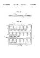
- FIG. 2shows one preferred embodiment of a solid state in-home audio player having the present invention smart trays incorporated therein;
- FIG. 2Ashows a rear view of one preferred embodiment of the smart tray
- FIG. 2Bshows a top plan view of the smart tray
- FIG. 3shows a block diagram illustration of circuit architecture for the present invention smart tray
- FIG. 4shows a detailed view of an interface portion of a receiving area in the smart tray
- FIG. 5illustrates the communication scheme between processors on the smart trays and the base digital signal processor
- FIG. 6shows an exemplary representation of an individual header stored within a music chip.
- the present invention "smart" audio player trayis used in a solid state audio system for providing communication between a semiconductor music chip recording medium having pre-recorded music stored thereon, and an audio player adapted for use with the chips.
- FIG. 1there is shown a block diagram of one preferred embodiment of a solid state audio system 10 which utilizes the present invention smart tray 20 for holding music chips and interfacing with a base portion of an audio player 12
- One or more music chips 16are coupled to the audio player 12 by means of the smart tray 20.
- the audio player 12is operated by means of a digital signal processor (DSP) 14 which communicates with the smart tray 20 in order to access information from the music chips.
- DSPdigital signal processor
- a suitable DSPfor example, for the music decoding operation of the audio player is DSP Model No. 1606 manufactured by the AT&T Corporation.
- the music chips 16are essentially memory devices having digital data stored thereon which corresponds to pre-recorded music.
- the pre-recorded audio datais stored on the chip 16 in a compressed format by means of an audio coding algorithm.
- the algorithmreduces the amount of digital information necessary to be stored from a master recording, while still reproducing essentially the same audio quality when the data is read back. Encoding by means of the algorithm is necessary in order to store sufficient quantities of data so that the music on the chips may have times of play comparable to that of current day albums.
- Other information pertaining to the musical content of the chipincluding a music category, artist and specific addressing information, is stored in a series of headers which are downloaded to the audio player once the chip is loaded.
- the main hardware architecture of the audio player 12consists of, besides the DSP 14 and smart tray 20, a stereo coder/decoder (code) 18, keypad 22, display 24, and associated interface logic in the form of an applications specific integrated circuit (ASIC) 26.
- the keypad and displaycomprise the user interface which allows for the making of custom music selections.
- the audio player 12is responsible for decoding the coded bit stream read from the music chip 16 and outputting the music through an output device, such as speakers or headphones 28. Parameters of the specific algorithm are downloaded into external RAM 30 when a chip 16 is loaded into the player 12 in order to assist in the decoding process.
- the player 12is a semi-stationary device for home/commercial use and is intended to blend and connect with a user's current entertainment system.
- the player 12includes a base portion 32 and a tiered upper portion 34 which includes the smart tray 20.
- the base portionhouses the DSP 14, also referred to as the base processor, the code 18, and associated logic for interfacing with the user.
- a remote control unit 36may also be included with the system as part of the user interface for performing user functions at a distance.
- the base portion 32 of the audio playerincludes a docking port 38 adapted to receive the remote control unit 36, wherein music selection information is uploaded to the remote in order that the user may perform intelligent selections.
- the upper tiered area 34 of the player as shownincludes a plurality of music tray receptacles 40.
- the tray receptacles 40are adapted to interconnect and stack on top of one another and also include a hollowed area 41 which is adapted to receive a music tray 20.
- the design of the home audio playeris intended to be flexible wherein additional trays 20 and tray receptacles 40, up to a finite number, can be easily plugged in and added as a user's collection of music chips grows. As shown in FIGS.
- the music tray 20is essentially a flat rectangular member having a plurality of receiving areas 42 for insertion of music chips.
- a pull tab handle 44 having an elliptical recess 46is included for easy manipulation of the tray.
- the music traymay include a cover flap portion 45 which is hingedly connected to the tray and adapted to enclose the music chips. It will be understood, however, that the music tray and tray receptacle may also be combined into a single stackable device which couples one to another and allows for the storage of multiple music chips.
- the receiving areas 42 of the tray 20are arranged in matrix form, having three rows A,B,C and six columns D,E,F,H,I,J to accommodate up to 18 chips. It will be understood, however, that the smart tray may be designed to accommodate other numbers of music chips and that the smart tray invention need not be confined to 18 slots.
- An interfaceis included within each of the receiving areas 42 of the smart tray 20 for communicating individually with the music chips.
- the music chips 16communicate with the audio player 12 by means of a capacitive coupling produced when dielectric plates on the chip and tray are aligned in close proximity.
- Power and clock signalsare provided to the chip 16 from the smart tray by contacts located on the sides of the receiving areas which bias and engage corresponding contacts on the chip when inserted.
- a notch 17 on the music chip 16corresponds with a blocking area 19 on the chip receptacles 40 of the tray and ensures that the chip cannot be inserted incorrectly, thereby minimizing damage from a possible wrongful insertion.
- the smart tray 20is partially filled with music chips, wherein receiving areas 42 in columns D,E and J are occupied.
- the smart trayis configured in a matrix-like format with each of the receiving areas being individually accessible by the base processor (DSP) 14.
- DSPbase processor
- Each tray 20contains a tray level processor 50 embedded within the housing of the smart tray to administer data transfer functions to the base level processor 14.
- the responsibilities of the tray processor 50include issuing data addresses, providing row and column access strobes for accessing individual chips, and executing any header content search commands for information stored on a chip that is requested by the base processor.
- the tray level processor 50is responsible for providing access strobes to the activated music chips. Accordingly, the tray level processor is shown coupled to respective decoders 52,53,54,55 for carrying out the access functions of the matrix, i.e., row select R S , column select C S , row enable R E and column enable C E
- An address and data bus 56,58are included in the smart tray for transmission of data to and from the music chip 16.
- the circuit architecture of a music chip 16is similar to that of a flash EEPROM, wherein memory cell are individually addressable via a parallel address bus and data is read/written over a parallel data buss.
- the contents of the chip 16are accessed by placing an address on the address bus 56 of the smart tray 20 and then activating the row and column select lines for the chip from which data is to be read.
- the data corresponding to that addressappears on the data bus 58 of the smart tray after propagation over the data interface with the chip 16 to a data register, e.g., shift register.
- FIG. 4an exemplary representation of the interface portion 60 of a receiving area 42 of the smart tray 20 is shown.
- Access to the address bus 56 and data bus 58 of the smart trayis governed by chip select and output enable signals, R S , C S and R E , C E , respectively.
- An address line 62is coupled from the tray level processor to the input of an AND gate 64 along with row and column select lines R S , C S .
- the output of the AND gate 64is coupled to an output terminal 66 of the smart tray for serial transmission of data to the music chip 16.
- both row and column select lines R S , C Smust be enabled in order to transmit an address through the AND gate 64 to the music chip 16.
- a data line 72 from the music chipis coupled to the input of a second AND gate 74 along with the row and column enable lines R E , C E from the tray level processor 50.
- the output of the second AND gate 74is coupled to the tray processor 50 through the data bus 58.
- both row and column enable R E , C Emust be enabled for transmission of data through the second AND gate 74. Since the data flow over the interface 60 between the music chip 16 and smart tray 20 is transferred in a serial fashion, it will be understood that data registers, for example, shift registers, may be interposed between the interface 60 on the smart tray and the address and data buses 56,58 to accommodate the transition from parallel to serial data.
- Both chip select and chip enable linesare included for access to a music chip in order to account for instances when the base processor 14 requests consecutive reads from separate storage chips. In this case, an address for the next data to be received would be issued to one chip through its R S , C S , while data is received by issuing R E , C E to the previously addressed chip.
- logic gates 64,74are shown in FIG. 4 as used to control the flow of data to and from the music chip, an alternative implementation is for the control signals to be present as active low enable signals on the data shift registers which are coupled to the address and data buses 56,58. In this way data transfer is inhibited from the shift registers unless the enable signals are present.
- a latent read schemeis employed so as to overcome the delay in transmission of data from the music chip 16 over the contactless interface 60.
- the data read from the data bus 58corresponds to the address issued in the previous read cycle.
- the tray processor 50issues an address during each read cycle that coincides with the next data it wishes to send the base processor 14.
- the tray processor 50reads the data requested in the previous read cycle and transfers it to the base processor 14. In this manner, data is always immediately available for transfer from the tray processor since the previous cycle's data is cued up to be read.
- the solid state audio system 10is an expandable system which is adapted for the add-on of multiple smart trays 20, up to a predetermined number.
- Each smart tray processor 50communicates with the base processor 14 via separate communication and data ports 76,77.
- a bit input/output (BIO) schemeis employed to indicate an engaged, i.e., populated and powered, tray 20 to the base processor 14.
- BIObit input/output
- each tray processor 50Upon power up, each tray processor 50 asserts an engaged/ready line.
- a separate BIO line 78is routed to the base processor for each tray slot. If a tray is absent at power up or is subsequently removed, the BIO line 78 is disengaged and no further communication is attempted with that tray.
- a command protocolexists to facilitate communication between the base processor 14 and tray processors 50.
- the base processor 14requests the play mode (e.g., sequential, random, content search, etc.), playback rate (e.g., normal play, paused, fast forward/reverse) and track selection.
- the tray processor 50directs encoded data from the chip 16 at the rate requested for playback.
- the tray processoris responsible for all address generation including that for fast/normal playback and access to the headers stored on each chip.
- the tray processor 50is also responsible for searching the header information in response to a specific request made through the base processor 14.
- the base processor 14functions to monitor the user interface, for example, the keypad 22, display 24 and the remote 36, for command input using vectored interrupts and also decodes the bit stream received from the tray processors 50 for playback. Utilizing this architecture, the base processor 14 need not be aware of the chip/bit addressing being performed at the tray level 50. This also decouples the base processor from the specifics of the chip interface which increases efficiency and allows for a more conventional processor architecture.
- Each music chip that is inserted into the smart traywill have a section of memory allocated to a table of contents. Track selections on the chip will be listed as pan of this table of contents by individual headers.
- the table of contentswill include information on play times song titles, music category and artist. Providing this information allows the chip 16 to self-register when it is loaded into a smart tray 20 of the audio player 12.
- FIG, 6there is shown one preferred embodiment of an individual header 80 which will correspond to a single track on the music chip 16.
- the individual headercontains a music category 82 to which the track belongs, for example, classical, jazz, country, rock, etc.
- an artist field 84 and addressing information 86for each track selection. Individual header information is self-registered with the RAM on the smart tray 20 once a chip 16 is inserted and powered up.
- the individual header conceptallows a user to maker music selections by category of music or artist which lends greater overall flexibility to the system. For example, a user may select to randomly hear Country Western songs over the course of an evening, or to hear songs from a specific artist, for example, Billy Joel. Music play may be performed randomly, sequentially, or by specific content as requested by the user.
- the music chips 16self-register their content information within the memory of the smart trays 20 search time is minimized and the base processor DSP 14 is allowed to focus on decoding the encoded bit stream so that its house-keeping activities are minimized.
- a tray level processor 50keeps track of what is on board its own tray, portability of the trays, i.e., removing trays from one player and installing them into another player, is done with minimal boot time.
Landscapes
- Engineering & Computer Science (AREA)
- Microelectronics & Electronic Packaging (AREA)
- Computer Hardware Design (AREA)
- Signal Processing For Digital Recording And Reproducing (AREA)
- Reverberation, Karaoke And Other Acoustics (AREA)
Abstract
Description
Claims (20)
Priority Applications (6)
| Application Number | Priority Date | Filing Date | Title |
|---|---|---|---|
| US08/447,322US5724482A (en) | 1995-05-22 | 1995-05-22 | Smart tray for audio player |
| EP96303615AEP0744751B1 (en) | 1995-05-22 | 1996-05-21 | Smart tray for audio player |
| DE69614313TDE69614313T2 (en) | 1995-05-22 | 1996-05-21 | Memory card tray for audio player |
| KR1019960017102AKR100248447B1 (en) | 1995-05-22 | 1996-05-21 | Apparatus for tray and apparatus for chip-memory using music |
| CA002176985ACA2176985C (en) | 1995-05-22 | 1996-05-21 | Smart tray for audio player |
| JP8126784AJPH0922588A (en) | 1995-05-22 | 1996-05-22 | Smart tray for audio player |
Applications Claiming Priority (1)
| Application Number | Priority Date | Filing Date | Title |
|---|---|---|---|
| US08/447,322US5724482A (en) | 1995-05-22 | 1995-05-22 | Smart tray for audio player |
Publications (1)
| Publication Number | Publication Date |
|---|---|
| US5724482Atrue US5724482A (en) | 1998-03-03 |
Family
ID=23775906
Family Applications (1)
| Application Number | Title | Priority Date | Filing Date |
|---|---|---|---|
| US08/447,322Expired - LifetimeUS5724482A (en) | 1995-05-22 | 1995-05-22 | Smart tray for audio player |
Country Status (6)
| Country | Link |
|---|---|
| US (1) | US5724482A (en) |
| EP (1) | EP0744751B1 (en) |
| JP (1) | JPH0922588A (en) |
| KR (1) | KR100248447B1 (en) |
| CA (1) | CA2176985C (en) |
| DE (1) | DE69614313T2 (en) |
Cited By (11)
| Publication number | Priority date | Publication date | Assignee | Title |
|---|---|---|---|---|
| US20020016748A1 (en)* | 2000-05-26 | 2002-02-07 | Comverse Network Systems, Ltd. | System and method enabling remote access to and customization of multimedia |
| US6425018B1 (en) | 1998-02-27 | 2002-07-23 | Israel Kaganas | Portable music player |
| US6824063B1 (en) | 2000-08-04 | 2004-11-30 | Sandisk Corporation | Use of small electronic circuit cards with different interfaces in an electronic system |
| US20050141178A1 (en)* | 2003-10-14 | 2005-06-30 | Philippe Feret | Visual serving tray and method |
| US20060195206A1 (en)* | 1997-11-24 | 2006-08-31 | Sigmatel, Inc. | Portable sound reproducing system and method |
| US7120509B1 (en)* | 1999-09-17 | 2006-10-10 | Hasbro, Inc. | Sound and image producing system |
| US20070142945A1 (en)* | 2000-10-12 | 2007-06-21 | Bose Corporation, A Delaware Corporation | Interactive Sound Reproducing |
| US20070182710A1 (en)* | 2005-04-13 | 2007-08-09 | Macdonald Frederic | Integrated material handling and displaying unit, system and method of use |
| US20070252694A1 (en)* | 2006-04-28 | 2007-11-01 | Motorola, Inc. | Radio frequency identification tag based tray and tray receiving method and apparatus |
| US20070252709A1 (en)* | 2006-04-28 | 2007-11-01 | Motorola, Inc. | Radio frequency identification tag based task effectuation method and apparatus |
| US20090198357A1 (en)* | 1996-10-02 | 2009-08-06 | James D. Logan And Kerry M. Logan Family Trust | Portable audio player |
Families Citing this family (1)
| Publication number | Priority date | Publication date | Assignee | Title |
|---|---|---|---|---|
| CN100479055C (en)* | 2006-04-11 | 2009-04-15 | 北京金山软件有限公司 | Audio playing method and system in game of mobile phone |
Citations (8)
| Publication number | Priority date | Publication date | Assignee | Title |
|---|---|---|---|---|
| US4287568A (en)* | 1977-05-31 | 1981-09-01 | Lester Robert W | Solid state music player using signals from a bubble-memory storage device |
| US4318188A (en)* | 1978-06-19 | 1982-03-02 | Siemens Aktiengesellschaft | Semiconductor device for the reproduction of acoustic signals |
| US4717261A (en)* | 1985-01-16 | 1988-01-05 | Casio Computer Co., Ltd. | Recording/reproducing apparatus including synthesized voice converter |
| US4772873A (en)* | 1985-08-30 | 1988-09-20 | Digital Recorders, Inc. | Digital electronic recorder/player |
| US4881205A (en)* | 1987-04-21 | 1989-11-14 | Casio Computer Co., Ltd. | Compact electronic apparatus with a refresh unit for a dynamic type memory |
| US4890259A (en)* | 1988-07-13 | 1989-12-26 | Information Storage Devices | High density integrated circuit analog signal recording and playback system |
| US4963866A (en)* | 1989-03-27 | 1990-10-16 | Digital Recorders, Inc. | Multi channel digital random access recorder-player |
| US5164915A (en)* | 1990-09-26 | 1992-11-17 | Information Storage Devices, Inc. | Cascading analog record/playback devices |
Family Cites Families (11)
| Publication number | Priority date | Publication date | Assignee | Title |
|---|---|---|---|---|
| JPS5938883A (en)* | 1982-08-30 | 1984-03-02 | Dainippon Printing Co Ltd | record |
| JPS6177184A (en)* | 1984-09-25 | 1986-04-19 | Toshiba Corp | Multi-disc automatic playback device |
| US4813014A (en)* | 1986-04-14 | 1989-03-14 | Phi Technologies, Inc. | Digital audio memory system |
| EP0294202A3 (en)* | 1987-06-03 | 1989-10-18 | Kabushiki Kaisha Toshiba | Digital sound data storing device |
| JPH0411288A (en)* | 1990-04-27 | 1992-01-16 | Brother Ind Ltd | Karaoke device with song search function |
| JPH0467490A (en)* | 1990-07-06 | 1992-03-03 | Pioneer Electron Corp | Information storing device and information reproducing device |
| JPH0478087A (en)* | 1990-07-13 | 1992-03-12 | Nippon Columbia Co Ltd | Autochanger |
| JPH0478986A (en)* | 1990-07-23 | 1992-03-12 | Okamoto Kosaku Kikai Seisakusho:Kk | Information storing and reproducing device |
| JPH0561492A (en)* | 1991-08-30 | 1993-03-12 | Hitachi Ltd | Karaoke (orchestration without lyrics) changer system for multi-media |
| JPH06111548A (en)* | 1992-09-28 | 1994-04-22 | Alpine Electron Inc | Digital audio medium changer system |
| JPH06309515A (en)* | 1993-04-19 | 1994-11-04 | Takaoka Electric Mfg Co Ltd | Reproduction method for audio/visual information |
- 1995
- 1995-05-22USUS08/447,322patent/US5724482A/ennot_activeExpired - Lifetime
- 1996
- 1996-05-21DEDE69614313Tpatent/DE69614313T2/ennot_activeExpired - Lifetime
- 1996-05-21EPEP96303615Apatent/EP0744751B1/ennot_activeExpired - Lifetime
- 1996-05-21CACA002176985Apatent/CA2176985C/ennot_activeExpired - Fee Related
- 1996-05-21KRKR1019960017102Apatent/KR100248447B1/ennot_activeExpired - Lifetime
- 1996-05-22JPJP8126784Apatent/JPH0922588A/enactivePending
Patent Citations (8)
| Publication number | Priority date | Publication date | Assignee | Title |
|---|---|---|---|---|
| US4287568A (en)* | 1977-05-31 | 1981-09-01 | Lester Robert W | Solid state music player using signals from a bubble-memory storage device |
| US4318188A (en)* | 1978-06-19 | 1982-03-02 | Siemens Aktiengesellschaft | Semiconductor device for the reproduction of acoustic signals |
| US4717261A (en)* | 1985-01-16 | 1988-01-05 | Casio Computer Co., Ltd. | Recording/reproducing apparatus including synthesized voice converter |
| US4772873A (en)* | 1985-08-30 | 1988-09-20 | Digital Recorders, Inc. | Digital electronic recorder/player |
| US4881205A (en)* | 1987-04-21 | 1989-11-14 | Casio Computer Co., Ltd. | Compact electronic apparatus with a refresh unit for a dynamic type memory |
| US4890259A (en)* | 1988-07-13 | 1989-12-26 | Information Storage Devices | High density integrated circuit analog signal recording and playback system |
| US4963866A (en)* | 1989-03-27 | 1990-10-16 | Digital Recorders, Inc. | Multi channel digital random access recorder-player |
| US5164915A (en)* | 1990-09-26 | 1992-11-17 | Information Storage Devices, Inc. | Cascading analog record/playback devices |
Cited By (40)
| Publication number | Priority date | Publication date | Assignee | Title |
|---|---|---|---|---|
| US20090198357A1 (en)* | 1996-10-02 | 2009-08-06 | James D. Logan And Kerry M. Logan Family Trust | Portable audio player |
| US20080004730A9 (en)* | 1997-11-24 | 2008-01-03 | Texas Mp3 Technologies, Ltd. | Portable sound reproducing system and method |
| US8170700B2 (en) | 1997-11-24 | 2012-05-01 | Mpman.Com, Inc. | Portable sound reproducing system and method |
| US8843225B2 (en) | 1997-11-24 | 2014-09-23 | Mpman.Com, Inc. | Portable sound reproducing system and method |
| US8615315B2 (en) | 1997-11-24 | 2013-12-24 | Mpman.Com, Inc. | Portable sound reproducing system and method |
| US8214064B2 (en) | 1997-11-24 | 2012-07-03 | Lg Electronics Inc. | Portable sound reproducing system and method |
| US20060195206A1 (en)* | 1997-11-24 | 2006-08-31 | Sigmatel, Inc. | Portable sound reproducing system and method |
| US8175727B2 (en) | 1997-11-24 | 2012-05-08 | Mpman.Com, Inc. | Portable sound reproducing system and method |
| US20070276522A9 (en)* | 1997-11-24 | 2007-11-29 | Texas Mp3 Technologies, Ltd. | Portable sound reproducing system and method |
| US20070038319A1 (en)* | 1997-11-24 | 2007-02-15 | Texas Mp3 Technologies, Ltd. | Portable sound reproducing system and method |
| US20070038320A1 (en)* | 1997-11-24 | 2007-02-15 | Texas Mp3 Technologies, Ltd. | Portable sound reproducing system and method |
| US20070112450A1 (en)* | 1997-11-24 | 2007-05-17 | Texas Mp3 Technologies, Ltd. | Portable sound reproducing system and method |
| US20070112449A1 (en)* | 1997-11-24 | 2007-05-17 | Texas Mp3 Technologies, Ltd. | Portable sound reproducing system and method |
| US20070112448A1 (en)* | 1997-11-24 | 2007-05-17 | Texas Mp3 Technologies, Ltd. | Portable sound reproducing system and method |
| US8116890B2 (en) | 1997-11-24 | 2012-02-14 | Mpman.Com, Inc. | Portable sound reproducing system and method |
| US6425018B1 (en) | 1998-02-27 | 2002-07-23 | Israel Kaganas | Portable music player |
| US7120509B1 (en)* | 1999-09-17 | 2006-10-10 | Hasbro, Inc. | Sound and image producing system |
| US20020016748A1 (en)* | 2000-05-26 | 2002-02-07 | Comverse Network Systems, Ltd. | System and method enabling remote access to and customization of multimedia |
| US7424446B2 (en)* | 2000-05-26 | 2008-09-09 | Comverse Network System, Ltd. | Apparatus and method for storing predetermined multimedia information |
| US7350714B2 (en) | 2000-08-04 | 2008-04-01 | Sandisk Corporation | Use of small electronic circuit cards with different interfaces in an electronic system |
| US20040256459A1 (en)* | 2000-08-04 | 2004-12-23 | Wallace Robert F. | Use of small electronic circuit cards with different interfaces in an electronic system |
| US7090124B2 (en) | 2000-08-04 | 2006-08-15 | Sandisk Corporation | Use of small electronic circuit cards with different interfaces in an electronic system |
| US6824063B1 (en) | 2000-08-04 | 2004-11-30 | Sandisk Corporation | Use of small electronic circuit cards with different interfaces in an electronic system |
| US20060202034A1 (en)* | 2000-08-04 | 2006-09-14 | Wallace Robert F | Use of Small Electronic Circuit Cards With Different Interfaces in an Electronic System |
| US8401682B2 (en) | 2000-10-12 | 2013-03-19 | Bose Corporation | Interactive sound reproducing |
| US20070142945A1 (en)* | 2000-10-12 | 2007-06-21 | Bose Corporation, A Delaware Corporation | Interactive Sound Reproducing |
| US10481855B2 (en) | 2000-10-12 | 2019-11-19 | Bose Corporation | Interactive sound reproducing |
| US8977375B2 (en) | 2000-10-12 | 2015-03-10 | Bose Corporation | Interactive sound reproducing |
| US8364295B2 (en) | 2000-10-12 | 2013-01-29 | Bose Corporation | Interactive sound reproducing |
| US10140084B2 (en) | 2000-10-12 | 2018-11-27 | Bose Corporation | Interactive sound reproducing |
| US9223538B2 (en) | 2000-10-12 | 2015-12-29 | Bose Corporation | Interactive sound reproducing |
| US20100179672A1 (en)* | 2000-10-12 | 2010-07-15 | Beckmann Paul E | Interactive Sound Reproducing |
| US20050141178A1 (en)* | 2003-10-14 | 2005-06-30 | Philippe Feret | Visual serving tray and method |
| US7692920B2 (en)* | 2003-10-14 | 2010-04-06 | Philippe Feret | Visual serving tray and method |
| US7289316B2 (en)* | 2003-10-14 | 2007-10-30 | Philippe Feret | Visual serving tray and method |
| US20070182710A1 (en)* | 2005-04-13 | 2007-08-09 | Macdonald Frederic | Integrated material handling and displaying unit, system and method of use |
| US7411502B2 (en)* | 2006-04-28 | 2008-08-12 | Motorola, Inc. | Radio frequency identification tag based tray and tray receiving method and apparatus |
| US20070252709A1 (en)* | 2006-04-28 | 2007-11-01 | Motorola, Inc. | Radio frequency identification tag based task effectuation method and apparatus |
| US20070252694A1 (en)* | 2006-04-28 | 2007-11-01 | Motorola, Inc. | Radio frequency identification tag based tray and tray receiving method and apparatus |
| US7528720B2 (en) | 2006-04-28 | 2009-05-05 | Motorola, Inc. | Radio frequency identification tag-based task effectuation method and apparatus |
Also Published As
| Publication number | Publication date |
|---|---|
| EP0744751B1 (en) | 2001-08-08 |
| KR960042645A (en) | 1996-12-21 |
| KR100248447B1 (en) | 2000-03-15 |
| JPH0922588A (en) | 1997-01-21 |
| DE69614313D1 (en) | 2001-09-13 |
| CA2176985C (en) | 2000-05-16 |
| DE69614313T2 (en) | 2002-07-25 |
| EP0744751A3 (en) | 1998-01-28 |
| CA2176985A1 (en) | 1996-11-23 |
| EP0744751A2 (en) | 1996-11-27 |
Similar Documents
| Publication | Publication Date | Title |
|---|---|---|
| USRE42550E1 (en) | Method and apparatus for portable digital entertainment system | |
| US5798921A (en) | Audio storage/reproduction system with automated inventory control | |
| US5724482A (en) | Smart tray for audio player | |
| CA2176983C (en) | Remote control for home audio system | |
| US20040088456A1 (en) | Smart hard-disk drive | |
| JP3886561B2 (en) | Memory chip architecture | |
| JP2007280414A (en) | Receiver and content storage device | |
| US6067279A (en) | Apparatus for skipping and/or playing tracks on a cd or a dvd | |
| JP4846908B2 (en) | Relative address assigning apparatus for digital data player and assigning method thereof | |
| US5276810A (en) | Information item selection apparatus producing multi-channel output signals | |
| US20010039603A1 (en) | Device bay storing solid state memory cards | |
| US20040267988A1 (en) | Smart hard-disk drive | |
| TW200923667A (en) | USB memory device | |
| US6493787B1 (en) | Device, system and method for accessing plate-shaped memory | |
| KR0128980Y1 (en) | Regeneration device mounting a lot of ic cards | |
| JPH02216687A (en) | Audio/music information management system and audio/music information management network system | |
| US20090310760A1 (en) | Audio Message Recorder with Flexible Control | |
| WO2004015712A1 (en) | Mp3 walkman with a replaceable hard disk | |
| JP2535856B2 (en) | Sound reproduction device | |
| JP3319607B2 (en) | Playback device | |
| KR200329876Y1 (en) | Flash memory cartridge | |
| JP2003178572A (en) | Hard disk unit and removal hard disk player, and disk reproducing device | |
| JPH01130689A (en) | Information offering system | |
| JPH01251467A (en) | Disk reproducing system and disk housing device | |
| JPH0535492Y2 (en) |
Legal Events
| Date | Code | Title | Description |
|---|---|---|---|
| AS | Assignment | Owner name:AT&T IPM CORP., FLORIDA Free format text:ASSIGNMENT OF ASSIGNORS INTEREST;ASSIGNORS:GREWE, ANTHONY JAMES;JAYANT, NUGGEHALLY SAMPATH;SHELBY, KEVIN ALAN;AND OTHERS;REEL/FRAME:007503/0868;SIGNING DATES FROM 19950516 TO 19950517 | |
| AS | Assignment | Owner name:LUCENT TECHNOLOGIES INC., NEW JERSEY Free format text:ASSIGNMENT OF ASSIGNORS INTEREST;ASSIGNOR:AT&T CORP.;REEL/FRAME:008697/0789 Effective date:19960329 | |
| FEPP | Fee payment procedure | Free format text:PAYOR NUMBER ASSIGNED (ORIGINAL EVENT CODE: ASPN); ENTITY STATUS OF PATENT OWNER: LARGE ENTITY | |
| STCF | Information on status: patent grant | Free format text:PATENTED CASE | |
| AS | Assignment | Owner name:THE CHASE MANHATTAN BANK, AS COLLATERAL AGENT, TEX Free format text:CONDITIONAL ASSIGNMENT OF AND SECURITY INTEREST IN PATENT RIGHTS;ASSIGNOR:LUCENT TECHNOLOGIES INC. (DE CORPORATION);REEL/FRAME:011722/0048 Effective date:20010222 | |
| FPAY | Fee payment | Year of fee payment:4 | |
| FPAY | Fee payment | Year of fee payment:8 | |
| AS | Assignment | Owner name:LUCENT TECHNOLOGIES INC., NEW JERSEY Free format text:TERMINATION AND RELEASE OF SECURITY INTEREST IN PATENT RIGHTS;ASSIGNOR:JPMORGAN CHASE BANK, N.A. (FORMERLY KNOWN AS THE CHASE MANHATTAN BANK), AS ADMINISTRATIVE AGENT;REEL/FRAME:018584/0446 Effective date:20061130 | |
| FPAY | Fee payment | Year of fee payment:12 | |
| AS | Assignment | Owner name:CREDIT SUISSE AG, NEW YORK Free format text:SECURITY INTEREST;ASSIGNOR:ALCATEL-LUCENT USA INC.;REEL/FRAME:030510/0627 Effective date:20130130 | |
| AS | Assignment | Owner name:ALCATEL-LUCENT USA INC., NEW JERSEY Free format text:RELEASE BY SECURED PARTY;ASSIGNOR:CREDIT SUISSE AG;REEL/FRAME:033950/0001 Effective date:20140819 |