US5724415A - Coin deflector for a coin telephone receptacle - Google Patents
Coin deflector for a coin telephone receptacleDownload PDFInfo
- Publication number
- US5724415A US5724415AUS08/497,426US49742695AUS5724415AUS 5724415 AUS5724415 AUS 5724415AUS 49742695 AUS49742695 AUS 49742695AUS 5724415 AUS5724415 AUS 5724415A
- Authority
- US
- United States
- Prior art keywords
- receptacle
- coins
- coin
- strip
- receiving device
- Prior art date
- Legal status (The legal status is an assumption and is not a legal conclusion. Google has not performed a legal analysis and makes no representation as to the accuracy of the status listed.)
- Expired - Lifetime
Links
Images

Classifications
- G—PHYSICS
- G07—CHECKING-DEVICES
- G07F—COIN-FREED OR LIKE APPARATUS
- G07F9/00—Details other than those peculiar to special kinds or types of apparatus
- G07F9/06—Coin boxes
Definitions
- the present inventionrelates to a coin deflector for coin receptacles associated with coin operated devices such as coin telephones.
- Coin operated devicessuch as coin telephones, must include a receptacle for collecting coins deposited in the device over multiple uses of the device.
- the coin receptacleis removed from the device at periodic intervals by service personnel and replaced by an empty receptacle.
- Considerable labor costis associated with collection visits, so it is desirable for the coin receptacles to have a large capacity, and to utilize all of the capacity of the receptacle to maximize the time between collection visits.
- the receptaclebecomes full, the device will become inoperative until the next collection visit, resulting in lost revenues.
- the present inventionsolves the problem of pyramiding and dead space within coin receptacles by providing a resilient, angled surface positioned in the path of the falling coins. Upon striking the resilient surface, the coins tend to spin or rotate and land flat, and are distributed throughout the receptacle. Dead space is significantly reduced, maximizing the interval between collection visits and minimizing the possibility of down time.
- the present inventionprovides a coin deflector for a coin receptacle that receives falling coins, comprising a resilient, angled surface positioned in the path of the falling coins and spaced above a bottom of the receptacle.
- the resilient, angled surfacecomprises a strip of resilient material, such as spring steel, attached at one end thereof to a side wall of the receptacle, and defining a free end opposite the attached end.
- the resilience of the materialpreferably is selected along with the distance the coins fall before sting the deflector, to impart a bounce to the coins.
- the angle of the deflectorpreferably is about 45°.
- the present inventionalso provides a coin telephone comprising a coin receptacle positioned to receive failing coins inserted into the telephone; and a coin deflector positioned in the path of the falling coins and spaced above a bottom of the receptacle, the deflector comprising a resilient, angled surface.
- an apparatusbounces coins from a rear entry point toward the front of the coin receptacle. This prevents the coins from pyramiding at the back part of the receptacle. The coins tend to fill the front portion of the receptacle first, and then slide toward the rear until the receptacle is substantially evenly filled.
- Such devicesmay include, without limitation, vending machines and coin operated games.
- an important object of the present inventionis to provide a method and apparatus for minimizing dead space within a coin receptacle.
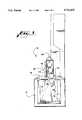
- FIG. 1is a diagrammatic pictorial view of a coin receptacle positioned below a relay mechanism of a coin telephone.
- FIG. 2is a more detailed pictorial view of the coin receptacle of FIG. 1.
- FIG. 3is a top view of the coin receptacle of FIG. 2.
- FIG. 4is a side cross sectional view taken along line 4--4 of FIG. 2.
- FIG. 1shows diagrammatically parts of a coin telephone 10, which includes a coin receptacle 12 embodying the present invention, shown in more detail in FIG. 2.
- the receptacle 12is a rectangular box of conventional shape designed to slide into position within the telephone 10 and to be easily removed in a known manner for secure transfer of the coins collected in the receptacle.
- the receptacleincludes a square upstanding collar 13 defining a top opening over which fits a cover 18, shown in FIG. 3.
- the coverdefines an opening for permitting coins to fall into the receptacle.
- the receptacle 12includes a plurality of side walls, including a front wall 14, a back wall 15, and a side wall 16. The side walls form vertical corners.
- a bottom wall 19 opposite the opening defined by the collar 13connects the side walls.
- a coin deflector 25is positioned within the receptacle 12.
- the deflector 25comprises a piece of resilient material bent to form an elongate deflector strip 28 separated from an attachment plate 32 by a right angle bend 30.
- the attachment plate 32is secured, such as at spot welds 34, to the side wall 16 near the corner formed with the back wall 15.
- the plate 32is attached at an angle to dispose the deflector strip 28 at an angle of about 45° with respect to the horizontal when the receptacle 12 is installed in a coin telephone.
- the receptacleis installed with the bottom 19 oriented horizontally, so that the strip 28 forms an angle of about 45° with the bottom surface 19.
- the gapshould be narrow enough to assure that coins do not often slip between the strip and the back wall.
- the width of the strip 25is 1/2 inch
- the lengthis 31/2 inches
- the gap 36is 1/4 inch
- the distance from coin releaseis 21/4 inches.
- the resilient stripmay be made of any material capable of providing a resilient surface.
- resilient surfaceas used herein means a surface which moves under the impact of a filling coin and springs back to impart energy to the coin, as opposed to a relatively rigid surface which essentially only deflects the coin's path.
- the purpose of using an angled, resilient surface as a deflectoris to impart spin or rotation to the coins, which then tend to lie flat, and to impart lateral motion to the coins sufficient so that they tend to be distributed throughout the receptacle.
- Various resilient materialscould be used for the deflector strip 28, such as metal, plastic, or other synthetic materials.
- the degree of resiliencemay be less if the coins are filling from a greater height, or if the coins are landing a greater distance from the attachment point of the strip.
- a more highly resilient materialsuch as rubber, could be attached to opposite side walls of the receptacle across the path of the coins in a manner providing a resilient surface.
- the stripmay be raised to a shorter distance from the coin release point, or the length of the strip may be reduced, if the material's resilience imparts more force to the coin.
- the optimum position of the strip in the horizontal planewill vary depending on where above the receptacle the coins are released.
- the coin receptacle 12is positioned within the telephone 10 beneath an exit slot 38 formed in the structure of a relay mechanism 40 of the telephone.
- FIG. 1shows several positions of a coin 50 as it makes its way through the relay mechanism 40.
- the weight of the coinmust depress a tongue 42, allowing the coin to enter a chute 43.
- the cointhen passes a diverter vane 45, which sends the coin either to the return chamber of the telephone (not shown) or to the receptacle 12.
- For coins directed to the receptacleafter the coins leave the diverter, they fall freely through the opening in the receptacle cover 18 until they strike the deflector strip 28, which is positioned in the path of the falling coins 50. The coins do not have a predictable orientation when they strike the strip 28.
- the stripWhen a coin hits the strip 28, the strip bends under the impact, and springs back, imparting a force to the coin. The action of the strip tends to cause the coin to rotate, and also imparts lateral movement to the coin, as shown in FIG. 1. Following this interaction, the coin tends to find a resting place lying flat, and the coins as a group tend to be well-distributed throughout the cross section of the receptacle.
Landscapes
- Physics & Mathematics (AREA)
- General Physics & Mathematics (AREA)
- Control Of Vending Devices And Auxiliary Devices For Vending Devices (AREA)
Abstract
Description
Claims (13)
Priority Applications (3)
| Application Number | Priority Date | Filing Date | Title |
|---|---|---|---|
| US08/497,426US5724415A (en) | 1995-06-30 | 1995-06-30 | Coin deflector for a coin telephone receptacle |
| PCT/US1996/010927WO1997002549A1 (en) | 1995-06-30 | 1996-06-26 | Coin deflector for a coin telephone receptacle |
| AU62914/96AAU6291496A (en) | 1995-06-30 | 1996-06-26 | Coin deflector for a coin telephone receptacle |
Applications Claiming Priority (1)
| Application Number | Priority Date | Filing Date | Title |
|---|---|---|---|
| US08/497,426US5724415A (en) | 1995-06-30 | 1995-06-30 | Coin deflector for a coin telephone receptacle |
Publications (1)
| Publication Number | Publication Date |
|---|---|
| US5724415Atrue US5724415A (en) | 1998-03-03 |
Family
ID=23976817
Family Applications (1)
| Application Number | Title | Priority Date | Filing Date |
|---|---|---|---|
| US08/497,426Expired - LifetimeUS5724415A (en) | 1995-06-30 | 1995-06-30 | Coin deflector for a coin telephone receptacle |
Country Status (3)
| Country | Link |
|---|---|
| US (1) | US5724415A (en) |
| AU (1) | AU6291496A (en) |
| WO (1) | WO1997002549A1 (en) |
Cited By (4)
| Publication number | Priority date | Publication date | Assignee | Title |
|---|---|---|---|---|
| US6052452A (en)* | 1998-07-15 | 2000-04-18 | Chuang; Tung-Wen | Pay phone |
| CN101288303B (en)* | 2005-08-19 | 2011-12-14 | 高通股份有限公司 | Picture-in-picture processing method and device for video telephony |
| JP2015148974A (en)* | 2014-02-07 | 2015-08-20 | Necプラットフォームズ株式会社 | Coin container |
| US9821944B1 (en)* | 2013-06-17 | 2017-11-21 | Amazon Technologies, Inc. | Package deceleration and protection systems |
Families Citing this family (3)
| Publication number | Priority date | Publication date | Assignee | Title |
|---|---|---|---|---|
| GB0106357D0 (en) | 2001-03-13 | 2001-05-02 | Federal Mogul Friction Product | Friction pad |
| DE102011076116A1 (en)* | 2011-05-19 | 2012-11-22 | Siemens Aktiengesellschaft | Coin channel and vending machine equipped with it |
| JP7361329B2 (en)* | 2019-09-12 | 2023-10-16 | ローレルバンクマシン株式会社 | Coin storage box and coin handling equipment |
Citations (20)
| Publication number | Priority date | Publication date | Assignee | Title |
|---|---|---|---|---|
| US1129552A (en)* | 1913-11-07 | 1915-02-23 | Walter T Cook | Fare-box. |
| GB176094A (en)* | 1920-11-26 | 1922-02-27 | Peter Gysbert Thomas De Villie | Improvements in coin collecting boxes particularly for coin-in-the-slot apparatus |
| GB338164A (en)* | 1929-08-12 | 1930-11-12 | Ferranti Ltd | Improvements relating to coin-freed mechanism |
| GB447296A (en)* | 1934-12-29 | 1936-05-15 | Measurement Ltd | Improvements relating to coin receptacles for prepayment meters |
| GB499654A (en)* | 1937-07-24 | 1939-01-24 | Lockerbie And Wilkinson Birmin | Improvements relating to locked coin-containers for use more especially with coin-freed apparatus |
| US2990113A (en)* | 1959-08-28 | 1961-06-27 | Fosbrink Howard | Chute structure for fare boxes |
| US3023275A (en)* | 1957-06-25 | 1962-02-27 | Ass Automation Ltd | Coin collectors for telecommunication services |
| US3204867A (en)* | 1963-06-04 | 1965-09-07 | Rockford Coca Cola Bottling Co | Bottle storage device |
| US3215239A (en)* | 1964-03-31 | 1965-11-02 | Crosse Cooler Co | Coin apportioning device for vending machines |
| US3842210A (en)* | 1971-02-02 | 1974-10-15 | Telephone Corp | Optional prepay coin operated telephone system |
| US3868483A (en)* | 1973-06-20 | 1975-02-25 | Amerace Corp | Self-latching security device for public coin-operated telephones |
| DE3134178A1 (en)* | 1981-08-28 | 1983-03-17 | Siemens AG, 1000 Berlin und 8000 München | Coin distributor for coin cassettes |
| US4787873A (en)* | 1987-12-17 | 1988-11-29 | Borrmann Lela R | Modular coin bank |
| US4841563A (en)* | 1987-01-12 | 1989-06-20 | Tamura Electric Works, Ltd. | Bucket type coin accumulation apparatus |
| US4928299A (en)* | 1989-05-26 | 1990-05-22 | Mars Incorporated | Coin operated telephone operation monitoring switch mounting arrangement |
| US5027390A (en)* | 1989-06-06 | 1991-06-25 | Protel, Inc. | Coin validation method and apparatus for a coin telephone or similar system having an escrow mechanism |
| US5054056A (en)* | 1990-08-29 | 1991-10-01 | Bell South Corporation | Tamper-deterrent device |
| US5058966A (en)* | 1991-01-11 | 1991-10-22 | Quadrum Telecommunications, Inc. | Vault liner for use in coin telephones |
| JPH05166043A (en)* | 1991-12-17 | 1993-07-02 | Fuji Electric Co Ltd | Coin box structure for automatic vending machine |
| US5272747A (en)* | 1988-09-09 | 1993-12-21 | Australian And Overseas Telecommunications Corp. Limited | Mobile pay telephone system |
- 1995
- 1995-06-30USUS08/497,426patent/US5724415A/ennot_activeExpired - Lifetime
- 1996
- 1996-06-26AUAU62914/96Apatent/AU6291496A/ennot_activeAbandoned
- 1996-06-26WOPCT/US1996/010927patent/WO1997002549A1/enactiveApplication Filing
Patent Citations (20)
| Publication number | Priority date | Publication date | Assignee | Title |
|---|---|---|---|---|
| US1129552A (en)* | 1913-11-07 | 1915-02-23 | Walter T Cook | Fare-box. |
| GB176094A (en)* | 1920-11-26 | 1922-02-27 | Peter Gysbert Thomas De Villie | Improvements in coin collecting boxes particularly for coin-in-the-slot apparatus |
| GB338164A (en)* | 1929-08-12 | 1930-11-12 | Ferranti Ltd | Improvements relating to coin-freed mechanism |
| GB447296A (en)* | 1934-12-29 | 1936-05-15 | Measurement Ltd | Improvements relating to coin receptacles for prepayment meters |
| GB499654A (en)* | 1937-07-24 | 1939-01-24 | Lockerbie And Wilkinson Birmin | Improvements relating to locked coin-containers for use more especially with coin-freed apparatus |
| US3023275A (en)* | 1957-06-25 | 1962-02-27 | Ass Automation Ltd | Coin collectors for telecommunication services |
| US2990113A (en)* | 1959-08-28 | 1961-06-27 | Fosbrink Howard | Chute structure for fare boxes |
| US3204867A (en)* | 1963-06-04 | 1965-09-07 | Rockford Coca Cola Bottling Co | Bottle storage device |
| US3215239A (en)* | 1964-03-31 | 1965-11-02 | Crosse Cooler Co | Coin apportioning device for vending machines |
| US3842210A (en)* | 1971-02-02 | 1974-10-15 | Telephone Corp | Optional prepay coin operated telephone system |
| US3868483A (en)* | 1973-06-20 | 1975-02-25 | Amerace Corp | Self-latching security device for public coin-operated telephones |
| DE3134178A1 (en)* | 1981-08-28 | 1983-03-17 | Siemens AG, 1000 Berlin und 8000 München | Coin distributor for coin cassettes |
| US4841563A (en)* | 1987-01-12 | 1989-06-20 | Tamura Electric Works, Ltd. | Bucket type coin accumulation apparatus |
| US4787873A (en)* | 1987-12-17 | 1988-11-29 | Borrmann Lela R | Modular coin bank |
| US5272747A (en)* | 1988-09-09 | 1993-12-21 | Australian And Overseas Telecommunications Corp. Limited | Mobile pay telephone system |
| US4928299A (en)* | 1989-05-26 | 1990-05-22 | Mars Incorporated | Coin operated telephone operation monitoring switch mounting arrangement |
| US5027390A (en)* | 1989-06-06 | 1991-06-25 | Protel, Inc. | Coin validation method and apparatus for a coin telephone or similar system having an escrow mechanism |
| US5054056A (en)* | 1990-08-29 | 1991-10-01 | Bell South Corporation | Tamper-deterrent device |
| US5058966A (en)* | 1991-01-11 | 1991-10-22 | Quadrum Telecommunications, Inc. | Vault liner for use in coin telephones |
| JPH05166043A (en)* | 1991-12-17 | 1993-07-02 | Fuji Electric Co Ltd | Coin box structure for automatic vending machine |
Cited By (4)
| Publication number | Priority date | Publication date | Assignee | Title |
|---|---|---|---|---|
| US6052452A (en)* | 1998-07-15 | 2000-04-18 | Chuang; Tung-Wen | Pay phone |
| CN101288303B (en)* | 2005-08-19 | 2011-12-14 | 高通股份有限公司 | Picture-in-picture processing method and device for video telephony |
| US9821944B1 (en)* | 2013-06-17 | 2017-11-21 | Amazon Technologies, Inc. | Package deceleration and protection systems |
| JP2015148974A (en)* | 2014-02-07 | 2015-08-20 | Necプラットフォームズ株式会社 | Coin container |
Also Published As
| Publication number | Publication date |
|---|---|
| AU6291496A (en) | 1997-02-05 |
| WO1997002549A1 (en) | 1997-01-23 |
Similar Documents
| Publication | Publication Date | Title |
|---|---|---|
| US5513738A (en) | Coin handling system | |
| US5724415A (en) | Coin deflector for a coin telephone receptacle | |
| US20100107944A1 (en) | Planter with Cup Belt Meter | |
| US3752168A (en) | Coin orienting, sorting and dispensing apparatus | |
| US4860922A (en) | Automatic dispenser for cylindrical commodities, in particular packets of coin | |
| US4010766A (en) | Change dispensing apparatus | |
| US5848725A (en) | Picking apparatus | |
| EP1049518B1 (en) | Dispenser | |
| GB2124913A (en) | Coin pusher amusement machine | |
| GB2226766A (en) | Coin pusher amusement machine | |
| US3906965A (en) | Coin separator and stacker | |
| HK483A (en) | Improvements relating to coin testing apparatus | |
| US4744470A (en) | Apparatus for separating agricultural produce from spurious matter | |
| DE3603754A1 (en) | GOODS MACHINE | |
| JP3508900B2 (en) | Vending machine product unloading device | |
| JPH089812Y2 (en) | Coin sorting / dispensing device | |
| US6758736B1 (en) | Coin or token sorting apparatus | |
| JP2504813B2 (en) | Coin processing equipment | |
| US3023873A (en) | Coin controlled dispensing machine | |
| US4227604A (en) | Coin selecting funnel | |
| JPH0587673U (en) | Coin handling equipment | |
| JPS6220064Y2 (en) | ||
| JP2602478Y2 (en) | Vending machine product unloading device | |
| US1731783A (en) | Coin-delivery chute | |
| JP3506218B2 (en) | Coin ejection chute |
Legal Events
| Date | Code | Title | Description |
|---|---|---|---|
| AS | Assignment | Owner name:BELLSOUTH CORPORATION, GEORGIA Free format text:ASSIGNMENT OF ASSIGNORS INTEREST;ASSIGNORS:MILLS, WOODROW W.;QUARLES, DENISE T.;REEL/FRAME:007701/0389 Effective date:19951004 Owner name:BELLSOUTH CORPORATION, GEORGIA Free format text:ASSIGNMENT OF ASSIGNORS INTEREST;ASSIGNOR:WARYJAS, MARCIA;REEL/FRAME:007701/0395 Effective date:19951018 | |
| STCF | Information on status: patent grant | Free format text:PATENTED CASE | |
| AS | Assignment | Owner name:BELLSOUTH INTELLECTUAL PROPERTY GROUP, INC., GEORG Free format text:ASSIGNMENT OF ASSIGNORS INTEREST;ASSIGNOR:BELLSOUTH CORPORATION;REEL/FRAME:009670/0482 Effective date:19980901 Owner name:BELLSOUTH INTELLECTUAL PROPERTY CORPORATION, DELAW Free format text:ASSIGNMENT OF ASSIGNORS INTEREST;ASSIGNOR:BELLSOUTH INTELLECTUAL PROPERTY GROUP, INC.;REEL/FRAME:009678/0367 Effective date:19980901 | |
| FPAY | Fee payment | Year of fee payment:4 | |
| FPAY | Fee payment | Year of fee payment:8 | |
| FPAY | Fee payment | Year of fee payment:12 |