US5724264A - Method and apparatus for tracking the position and orientation of a stylus and for digitizing a 3-D object - Google Patents
Method and apparatus for tracking the position and orientation of a stylus and for digitizing a 3-D objectDownload PDFInfo
- Publication number
- US5724264A US5724264AUS08/512,084US51208495AUS5724264AUS 5724264 AUS5724264 AUS 5724264AUS 51208495 AUS51208495 AUS 51208495AUS 5724264 AUS5724264 AUS 5724264A
- Authority
- US
- United States
- Prior art keywords
- probe
- stylus
- turntable
- recited
- rotary table
- Prior art date
- Legal status (The legal status is an assumption and is not a legal conclusion. Google has not performed a legal analysis and makes no representation as to the accuracy of the status listed.)
- Expired - Lifetime
Links
Images


Classifications
- B—PERFORMING OPERATIONS; TRANSPORTING
- B25—HAND TOOLS; PORTABLE POWER-DRIVEN TOOLS; MANIPULATORS
- B25J—MANIPULATORS; CHAMBERS PROVIDED WITH MANIPULATION DEVICES
- B25J9/00—Programme-controlled manipulators
- B25J9/16—Programme controls
- B25J9/1679—Programme controls characterised by the tasks executed
- B25J9/1692—Calibration of manipulator
- G—PHYSICS
- G01—MEASURING; TESTING
- G01B—MEASURING LENGTH, THICKNESS OR SIMILAR LINEAR DIMENSIONS; MEASURING ANGLES; MEASURING AREAS; MEASURING IRREGULARITIES OF SURFACES OR CONTOURS
- G01B21/00—Measuring arrangements or details thereof, where the measuring technique is not covered by the other groups of this subclass, unspecified or not relevant
- G01B21/02—Measuring arrangements or details thereof, where the measuring technique is not covered by the other groups of this subclass, unspecified or not relevant for measuring length, width, or thickness
- G01B21/04—Measuring arrangements or details thereof, where the measuring technique is not covered by the other groups of this subclass, unspecified or not relevant for measuring length, width, or thickness by measuring coordinates of points
- G01B21/042—Calibration or calibration artifacts
- G—PHYSICS
- G01—MEASURING; TESTING
- G01B—MEASURING LENGTH, THICKNESS OR SIMILAR LINEAR DIMENSIONS; MEASURING ANGLES; MEASURING AREAS; MEASURING IRREGULARITIES OF SURFACES OR CONTOURS
- G01B5/00—Measuring arrangements characterised by the use of mechanical techniques
- G01B5/004—Measuring arrangements characterised by the use of mechanical techniques for measuring coordinates of points
- G01B5/008—Measuring arrangements characterised by the use of mechanical techniques for measuring coordinates of points using coordinate measuring machines
- G—PHYSICS
- G05—CONTROLLING; REGULATING
- G05B—CONTROL OR REGULATING SYSTEMS IN GENERAL; FUNCTIONAL ELEMENTS OF SUCH SYSTEMS; MONITORING OR TESTING ARRANGEMENTS FOR SUCH SYSTEMS OR ELEMENTS
- G05B19/00—Programme-control systems
- G05B19/02—Programme-control systems electric
- G05B19/42—Recording and playback systems, i.e. in which the programme is recorded from a cycle of operations, e.g. the cycle of operations being manually controlled, after which this record is played back on the same machine
- G05B19/4202—Recording and playback systems, i.e. in which the programme is recorded from a cycle of operations, e.g. the cycle of operations being manually controlled, after which this record is played back on the same machine preparation of the programme medium using a drawing, a model
- G05B19/4207—Recording and playback systems, i.e. in which the programme is recorded from a cycle of operations, e.g. the cycle of operations being manually controlled, after which this record is played back on the same machine preparation of the programme medium using a drawing, a model in which a model is traced or scanned and corresponding data recorded
- G—PHYSICS
- G06—COMPUTING OR CALCULATING; COUNTING
- G06F—ELECTRIC DIGITAL DATA PROCESSING
- G06F3/00—Input arrangements for transferring data to be processed into a form capable of being handled by the computer; Output arrangements for transferring data from processing unit to output unit, e.g. interface arrangements
- G06F3/01—Input arrangements or combined input and output arrangements for interaction between user and computer
- G06F3/016—Input arrangements with force or tactile feedback as computer generated output to the user
- G—PHYSICS
- G06—COMPUTING OR CALCULATING; COUNTING
- G06F—ELECTRIC DIGITAL DATA PROCESSING
- G06F3/00—Input arrangements for transferring data to be processed into a form capable of being handled by the computer; Output arrangements for transferring data from processing unit to output unit, e.g. interface arrangements
- G06F3/01—Input arrangements or combined input and output arrangements for interaction between user and computer
- G06F3/03—Arrangements for converting the position or the displacement of a member into a coded form
- G06F3/033—Pointing devices displaced or positioned by the user, e.g. mice, trackballs, pens or joysticks; Accessories therefor
- G06F3/0346—Pointing devices displaced or positioned by the user, e.g. mice, trackballs, pens or joysticks; Accessories therefor with detection of the device orientation or free movement in a 3D space, e.g. 3D mice, 6-DOF [six degrees of freedom] pointers using gyroscopes, accelerometers or tilt-sensors
- G—PHYSICS
- G06—COMPUTING OR CALCULATING; COUNTING
- G06F—ELECTRIC DIGITAL DATA PROCESSING
- G06F3/00—Input arrangements for transferring data to be processed into a form capable of being handled by the computer; Output arrangements for transferring data from processing unit to output unit, e.g. interface arrangements
- G06F3/01—Input arrangements or combined input and output arrangements for interaction between user and computer
- G06F3/03—Arrangements for converting the position or the displacement of a member into a coded form
- G06F3/033—Pointing devices displaced or positioned by the user, e.g. mice, trackballs, pens or joysticks; Accessories therefor
- G06F3/038—Control and interface arrangements therefor, e.g. drivers or device-embedded control circuitry
- G06F3/0383—Signal control means within the pointing device
- A—HUMAN NECESSITIES
- A63—SPORTS; GAMES; AMUSEMENTS
- A63F—CARD, BOARD, OR ROULETTE GAMES; INDOOR GAMES USING SMALL MOVING PLAYING BODIES; VIDEO GAMES; GAMES NOT OTHERWISE PROVIDED FOR
- A63F2300/00—Features of games using an electronically generated display having two or more dimensions, e.g. on a television screen, showing representations related to the game
- A63F2300/10—Features of games using an electronically generated display having two or more dimensions, e.g. on a television screen, showing representations related to the game characterized by input arrangements for converting player-generated signals into game device control signals
- A63F2300/1037—Features of games using an electronically generated display having two or more dimensions, e.g. on a television screen, showing representations related to the game characterized by input arrangements for converting player-generated signals into game device control signals being specially adapted for converting control signals received from the game device into a haptic signal, e.g. using force feedback
- G—PHYSICS
- G05—CONTROLLING; REGULATING
- G05B—CONTROL OR REGULATING SYSTEMS IN GENERAL; FUNCTIONAL ELEMENTS OF SUCH SYSTEMS; MONITORING OR TESTING ARRANGEMENTS FOR SUCH SYSTEMS OR ELEMENTS
- G05B2219/00—Program-control systems
- G05B2219/30—Nc systems
- G05B2219/37—Measurements
- G05B2219/37021—Robot controls position of touch probe
- G—PHYSICS
- G05—CONTROLLING; REGULATING
- G05B—CONTROL OR REGULATING SYSTEMS IN GENERAL; FUNCTIONAL ELEMENTS OF SUCH SYSTEMS; MONITORING OR TESTING ARRANGEMENTS FOR SUCH SYSTEMS OR ELEMENTS
- G05B2219/00—Program-control systems
- G05B2219/30—Nc systems
- G05B2219/37—Measurements
- G05B2219/37043—Touch probe, store position of touch point on surface
- G—PHYSICS
- G05—CONTROLLING; REGULATING
- G05B—CONTROL OR REGULATING SYSTEMS IN GENERAL; FUNCTIONAL ELEMENTS OF SUCH SYSTEMS; MONITORING OR TESTING ARRANGEMENTS FOR SUCH SYSTEMS OR ELEMENTS
- G05B2219/00—Program-control systems
- G05B2219/30—Nc systems
- G05B2219/39—Robotics, robotics to robotics hand
- G05B2219/39015—With different manipulator configurations, contact known sphere, ballbar
- G—PHYSICS
- G05—CONTROLLING; REGULATING
- G05B—CONTROL OR REGULATING SYSTEMS IN GENERAL; FUNCTIONAL ELEMENTS OF SUCH SYSTEMS; MONITORING OR TESTING ARRANGEMENTS FOR SUCH SYSTEMS OR ELEMENTS
- G05B2219/00—Program-control systems
- G05B2219/30—Nc systems
- G05B2219/39—Robotics, robotics to robotics hand
- G05B2219/39021—With probe, touch reference positions
- G—PHYSICS
- G05—CONTROLLING; REGULATING
- G05B—CONTROL OR REGULATING SYSTEMS IN GENERAL; FUNCTIONAL ELEMENTS OF SUCH SYSTEMS; MONITORING OR TESTING ARRANGEMENTS FOR SUCH SYSTEMS OR ELEMENTS
- G05B2219/00—Program-control systems
- G05B2219/30—Nc systems
- G05B2219/39—Robotics, robotics to robotics hand
- G05B2219/39024—Calibration of manipulator
- G—PHYSICS
- G05—CONTROLLING; REGULATING
- G05B—CONTROL OR REGULATING SYSTEMS IN GENERAL; FUNCTIONAL ELEMENTS OF SUCH SYSTEMS; MONITORING OR TESTING ARRANGEMENTS FOR SUCH SYSTEMS OR ELEMENTS
- G05B2219/00—Program-control systems
- G05B2219/30—Nc systems
- G05B2219/39—Robotics, robotics to robotics hand
- G05B2219/39048—Closed loop kinematic self calibration, grip part of robot with hand
- G—PHYSICS
- G05—CONTROLLING; REGULATING
- G05B—CONTROL OR REGULATING SYSTEMS IN GENERAL; FUNCTIONAL ELEMENTS OF SUCH SYSTEMS; MONITORING OR TESTING ARRANGEMENTS FOR SUCH SYSTEMS OR ELEMENTS
- G05B2219/00—Program-control systems
- G05B2219/30—Nc systems
- G05B2219/45—Nc applications
- G05B2219/45055—Assembly
- G—PHYSICS
- G05—CONTROLLING; REGULATING
- G05B—CONTROL OR REGULATING SYSTEMS IN GENERAL; FUNCTIONAL ELEMENTS OF SUCH SYSTEMS; MONITORING OR TESTING ARRANGEMENTS FOR SUCH SYSTEMS OR ELEMENTS
- G05B2219/00—Program-control systems
- G05B2219/30—Nc systems
- G05B2219/45—Nc applications
- G05B2219/45061—Measuring robot
- G—PHYSICS
- G06—COMPUTING OR CALCULATING; COUNTING
- G06F—ELECTRIC DIGITAL DATA PROCESSING
- G06F2203/00—Indexing scheme relating to G06F3/00 - G06F3/048
- G06F2203/01—Indexing scheme relating to G06F3/01
- G06F2203/015—Force feedback applied to a joystick
- H—ELECTRICITY
- H01—ELECTRIC ELEMENTS
- H01H—ELECTRIC SWITCHES; RELAYS; SELECTORS; EMERGENCY PROTECTIVE DEVICES
- H01H3/00—Mechanisms for operating contacts
- H01H2003/008—Mechanisms for operating contacts with a haptic or a tactile feedback controlled by electrical means, e.g. a motor or magnetofriction
Definitions
- the present inventionrelates generally to input devices for interfacing with computer systems, and more particularly to computer input devices that provide spatial information about a three-dimensional object to computer systems which provide a representation of the object.
- Three-dimensional (3-D) digitizationis the process of sensing a three-dimensional object and creating a three-dimensional representation of the object which can be manipulated as digital data by a computer system.
- Detailed and accurate three-dimensional modelscan be created and manipulated by computer systems for use by animators, engineers, scientists, designers, architects, and others who have a need for a realistic three-dimensional, manipulable model derived from a real, physical object.
- a common type of digitizing apparatusutilizes a probe device, such as a stylus or other pointer, to trace over surfaces a three-dimensional object and thereby provide the spatial coordinate data of the object to a host computer system.
- the host computer systemcan sample the probe device to receive discrete data points at different spatial coordinates.
- the pointscan be joined together and displayed as a "mesh representation", which is a wire-frame type model comprising a set of vertices with interconnecting lines or polygons (typically called a "data set").
- a realistic 3-dimensional shaded modelcan be created by a computer system from the mesh representation of an object.
- a common type of probe apparatusutilizes mechanical linkages and sensors to determine the position of the stylus or other probe that is tracing the three-dimensional object.
- the stylusis fixed to one end of a series of mechanical linkages, and the other end of the linkage chain is connected to a base fixed to a stationary surface.
- Sensorscan be included in joints of the linkage chain to sense the relative orientation of linkages, and therefore the stylus, are located with respect to the base.
- the angle data read by the sensorscan be converted into coordinate data by a microprocessor interface or by the host computer system.
- the useris further constrained by the joints of the linkage assembly. Since wires are routed through the joints to carry electrical signals from sensors located therein, the joints typically include stops which limit the motion of a joint to under 360 degrees to prevent twisting and stressing the wires.
- this limited movementcan inconvenience the user when tracing an object, especially when a limit to a joint is reached in a particular direction and further movement of the stylus in that direction is required to trace the surface of the object.
- Digitizing apparatusesoften use less expensive relative sensors which detect a change in the position of a linkage of the digitizing apparatus rather than reading an absolute angle for the position of the linkage.
- a "zeroing" procedureis often accomplished each time the apparatus is powered up to provide reference starting angles for the relative sensors. For example, in the prior art, zeroing can be accomplished by moving each individual joint to a stop of the joint and starting angles are "zeroed" at those points.
- this procedurecan be very time consuming to move each individual joint each time the apparatus is powered up.
- digitizing apparatusesuse a "home position" to provide starting angles.
- the stylusis placed into a receptacle on the base of the apparatus such that the reference starting angles for all the sensors is known when the apparatus is powered up.
- having the receptacle for a home position on the base of the apparatustypically requires a larger base that covers a larger surface area on a support surface such as a tabletop, which can be inconvenient.
- the more degrees of freedom on a digitizing apparatusthe more joints that need to be zeroed between the base and the probe. The greater the number joints to be zeroed, the greater the chance for error to be introduced in the zeroing process.
- the present inventionprovides a measuring system for measuring three-dimensional (3-D) coordinates.
- the probe apparatusis used to digitize three-dimensional objects into a mesh representation manipulable by a computer system.
- Various improvements to a probe arm linkage, a calibration method and zeroing method for a probe apparatus, a rotary table for supporting an object to be digitized, a method for developing a mesh representation by a computer system, and a method for assembling a probe arm linkageare described herein.
- a probe apparatus of the present invention for sensing the position and orientation of a probefor sensing the position and orientation of a probe, such as a stylus, includes a first joint member coupled to the probe that provides two degrees of freedom to the probe, and a first linkage rotatably coupled to the first joint member. Further, a second joint member is rigidly coupled to the first linkage and provides one degree of freedom to the probe. A second linkage is rigidly coupled to the second joint member, and a third joint member is rotatably coupled to the other end of the second linkage. The third joint member provides two degrees of freedom to the probe. Finally, a support base is coupled to the third joint member for supporting the probe apparatus. Transducers of the probe apparatus provide angular signals for the provided degrees of freedom to describe a position and orientation of the probe.
- the probe apparatusprovides 3-D data describing a 3-D object to the computer system.
- An electronics interfaceis included within a housing of said support base and provides the angular signals from the sensors to a computer system.
- the joint memberscan include a multistage stop joint of the present invention which provides over 360 degrees of rotational movement about an axis.
- the transducer for one of the first joint member degrees of freedomis positioned in the second joint member.
- the first joint membercan provide three degrees of freedom to the probe in an alternate embodiment.
- a method of the present invention for calibrating a probe apparatus for measuring 3-D coordinatesincludes a step of sampling multiple orientations of the stylus as the orientation of the stylus is varied at an arbitrary point within the probe's work volume. The position of the stylus tip remains fixed while the user varies the orientation of the stylus. Multiple orientations are sampled from data provided by sensors on the probe apparatus. Spatial coordinates are then determined for the stylus at each of the sampled orientations of the stylus. Next, error values between the spatial coordinates of the sampled orientations are determined. Finally, the probe apparatus is optimized by determining calibration parameters based on the error values and using the calibration parameters when determining the position and orientation of the probe during normal operation.
- previous calibration parametersare loaded from a memory device before the calibration process and are adjusted to become new calibration parameters.
- the adjusted parametersare preferably stored on an EPROM memory device which is unable to store data over previously written data stored in the EPROM.
- the adjusted calibration parametersare stored as a most recent set of calibration parameters in a specific section of the EPROM such that, when calibration parameters are retrieved during operation of the probe apparatus, only the most recent set of calibration parameters are retrieved.
- the calibration stepscan be repeated when the stylus is placed at a different position in the selected volume and the sampled orientations from both of the positions can be used when determining the error values.
- a method of the present invention for zeroing the sensors of a probe apparatus of a three-dimensional coordinate measuring system having relative sensors, such as the probe apparatus described above,includes placing the stylus (or other probe) in a receptacle positioned on one of the joints or one of the linkages of the probe apparatus.
- This receptaclepreferably takes the form of a small bore or shallow divot.
- the linkage arm assemblycan be in only one possible configuration while the stylus is positioned in the receptacle; this one configuration is known as a "home position.”
- An indicationis then received to zero the sensors of the probe apparatus, such as powering up the probe apparatus.
- Starting anglesare then assigned to the sensors when the probe apparatus is in the home position. The starting angles provide a zero angle reference for the sensors of the probe apparatus. Preferably, the starting angles have previously been calibrated for the particular probe apparatus that is undergoing the zeroing process.
- a rotary table of the present inventionis for use with a 3-D digitizing system that includes a probe apparatus for measuring 3-D coordinates on an object resting on the rotary table, such as the probe apparatus described above.
- the rotary tableincludes a support base and a turntable which rotates.
- a sensoris coupled to the support base which measures an angular rotation of the turntable and provides the angular rotation to a host computer system.
- the host computer systemincludes the turntable rotation in a determination of the position and orientation of the probe when the probe is contacting the object resting on the turntable.
- the angular rotationis included in the probe determination when the probe has contacted the object before the turntable has been rotated and after the turntable has been rotated so that the object can be referenced at its new position.
- the sensoris preferably positioned near the center of said turntable such that a shaft of the sensor is coupled to the turntable.
- the turntablealso preferably includes a receptacle positioned near a periphery (or the center) of the turntable for receiving the probe in an initialization procedure for locating the turntable relative to the probe apparatus.
- the initialization procedurecan include placing the probe in the receptacle, rotating the turntable while the probe is positioned in the receptacle, sampling multiple positions and orientations of the probe as the turntable is rotated, and determining the position and orientation of the rotary table relative to the probe apparatus using the sampled positions and orientations of the probe.
- the support base of the tableis coupled to the base of the probe apparatus such that the position and orientation of the rotary table is fixed relative to the probe apparatus.
- a method of the present invention for developing a mesh representation of a three-dimensional object by a computer systemincludes receiving a data point from a probe corresponding to a surface point on a surface of a three-dimensional (3-D) object.
- the data pointis added to an end of a current contour line of the mesh representation, where the current contour line includes data points corresponding to surface points on the surface of the 3-D object.
- a triangleis then created in the mesh representation that includes a data point of the current contour line, a data point of a previous contour line, and a third data point from either the current contour line or the previous contour line.
- the previous contour lineis adjacent to the current contour line and includes data points previously received from the probe. The triangle is created only when the current contour line is not the first and only contour line of the mesh representation.
- data points of the triangleare chosen based on the distance between data points of the current contour line and data points of the previous contour line.
- a normal vectoris assigned to the created triangle that indicates the exterior surface of the mesh representation.
- the orientation of the normal vectoris based on orientation data included in the data points of the triangle.
- the triangleis displayed on a display screen of the host computer immediately after the triangle is created, thus displaying the mesh representation incrementally.
- a triangleis created for each data point of the previous contour line that is not included in a triangle in a "close mesh" process.
- the data pointsare provided to the host computer from the probe as a user is tracing the probe across the surface of the object.
- the data pointscan be provided when a user control is activated or after the user traces the probe a minimum distance on the object.
- a method of the present invention for providing a selection template that allows commands to be selected by a probe apparatusincludes defining a template area as the selection template within a selected volume that the stylus of the probe apparatus can reach.
- a selection areais defined within the template area and is associated with a command to the host computer.
- the command associated with the selection areais provided to the host computer to select a function of said host computer or of the probe apparatus when the tip of the stylus is positioned within the selection area.
- a plurality of selection areasare defined within the template area that are each associated with a different command.
- the selection areascan include indicia such as icons and labels.
- a method of the present inventionis also described for assembling a linkage assembly including a plurality of joints and a linkage used in a probe apparatus for measuring three-dimensional coordinates, such as the probe described above.
- Two joint fixturesare positioned a desired distance apart and have a desired angle offset from each other.
- a joint of the linkage assemblyis placed in each of the joint fixtures.
- the jointscan be moved relative to the linkage connecting the joints so that the joints fit in the joint fixtures.
- the jointsare then bonded to the linkage while the joints are placed in the joint fixtures.
- the linkageis preferably made of graphite, which is well adapted to the bonding process.
- the probe arm apparatusprovides a lightweight, accurate device for the user to handle.
- the calibration methodallows a probe to be positioned at an arbitrary point in a volume and thus avoid expensive precision fixtures.
- the zeroing methodis more accurate and allows only one possible physical configuration of the probe arm to be in the home position.
- the method of the present invention for assembling linkages and joints for a probe apparatusallows accurate lengths and angles between joints.
- the rotary tableallows an object to be re-oriented by a user during digitization without a cumbersome procedure and with great accuracy.
- the method for developing a mesh representationallows a user to incrementally view a mesh representation and quickly and accurately finds the orientation of the mesh polygons.
- the selection templateallows the user to conveniently select commands and functions of the host computer and probe during a digitization process.
- FIG. 1is a perspective view of a measuring and digitizing system in accordance with the present invention
- FIG. 1ais a block diagram of interface electronics for use with the digitizing system of FIG. 1;
- FIG. 2is a flow diagram illustrating a method of initializing and using the digitizing system of FIG. 1;
- FIG. 3ais a flow diagram illustrating a zeroing process for the probe apparatus of the digitizing system
- FIG. 3bis a flow diagram illustrating an alternate zeroing process to the process of FIG. 3a;
- FIG. 4is a perspective view of the probe apparatus of FIG. 1 in a home position
- FIG. 4ais a detail view of the aperture for holding the stylus in the home position
- FIG. 5is a flow diagram illustrating a calibration process of the present invention for the probe apparatus of FIG. 1;
- FIG. 6is a flow diagram illustrating a process of initializing a rotary table and selection template of the present invention
- FIG. 7is a perspective view of the rotary table of the present invention.
- FIG. 8is a top plan view of the selection template of the present invention.
- FIG. 9is a perspective view of an object that is to be digitized by the present invention.
- FIG. 10is a diagrammatic view of a mesh representation of the object shown in FIG. 9;
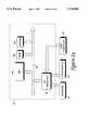
- FIG. 11is a flow diagram illustrating a process of the present invention for developing a mesh representation such as the one shown in FIG. 10;
- FIG. 12is a flow diagram illustrating the step of FIG. 11 for creating triangles in a mesh representation
- FIG. 13is a diagram illustrating an example mesh representation developed by the process of FIG. 11;
- FIG. 14is a flow diagram illustrating the step of FIG. 12 for adding triangles between two contour lines of the mesh representation
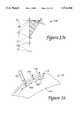
- FIGS. 15a, 15b, 15c, 15d, and 15eare diagrams illustrating the method of FIG. 12 for adding triangles using the mesh representation of FIG. 13;
- FIG. 16is a diagram illustrating the normal vectors for triangles added to the mesh representation
- FIG. 17is a flow diagram illustrating the step of FIG. 11 for closing the mesh representation
- FIGS. 18a and 18bare diagrams of a mesh representation illustrating the process of FIG. 17 for closing a mesh representation
- FIG. 19is a flow diagram illustrating a method of assembling linkage assemblies used in the probe apparatus of FIG. 1;
- FIG. 20is a schematic diagram illustrating the method of FIG. 19.
- FIGS. 21a and 21bare front and side views of a multistage stop joint of the present invention for use with the probe apparatus of FIG. 1.
- a digitizing system 10 for measuring a three-dimensional (3-D) object and providing a representation of the three-dimensional object in a computer systemincludes a probe apparatus 12, a rotary table 14, an electronic interface 16, and a host computer 18.
- a three-dimensional object 20is shown resting on rotary table 14.
- the illustrated digitizing system 10is directed to providing a highly accurate representation of object 20 which host computer 18 can display, edit, copy, provide to other computer systems, or otherwise manipulate.
- Probe apparatus 12is provided to allow a user to measure and transmit location information of object 20 to host computer 18.
- a probe that is traced over a 3-D object, such as object 20can provide coordinate information describing the 3-D geometry of object 20.
- this coordinate informationis provided using sensors operative to measure positions of the probe apparatus as it is moved to various locations with respect to the fixed base. This is described in greater detail below.
- Probe apparatus 12preferably includes a stylus probe 22 and a mechanical linkage assembly 25.
- Stylus 22is a pen-like rod that can be manipulated between a user's fingers to allow a fine degree of control of the probe apparatus.
- Stylus 22includes a tip 23 that is used to reference the location of a point pointed to by the probe apparatus.
- Probes other than stylus 22can be used in other embodiments. For example, a curved or angled member, hand grip, palm-supported stylus, or other type of probe can be used.
- Stylus 22is coupled to mechanical linkage assembly 25.
- Linkage assembly 25(or “arm") preferably includes joint members 24, 26, and 28, linkages 30, 32 and 34, and base 33.
- Base 33also preferably includes a base joint 35 coupled between the base and linkage 34.
- Stylus 22is coupled to linkage 30 via joint member 24, and linkage 30 is coupled to linkage 32 via joint member 26.
- Linkage 32is coupled to base 33 via joint member 28.
- Base 33is preferably securely placed upon or fixed to a support surface 37, such as a tabletop.
- joint member 24, 26, 28, and 35provides one or more degrees of freedom to stylus 22 within three-dimensional coordinate space defined by x-axis 36, y-axis 38, and z-axis 40 with respect to fixed base 33.
- joint member 24includes two joints which allow stylus 22 to move about axis A1, as shown by arrows 42 and about axis A2, as shown by arrows 44.
- joint member 24 and stylus 22can be rotated about axis A2 while linkage 30 remains fixed in joint member 26.
- Joint member 26includes one joint that allows stylus 22, joint member 24, and linkage 30 to move about axis A3, as shown by arrows 46.
- Joint member 28includes two joints that allow stylus 22, joint members 24 and 26, and linkages 30 and 32 to move about axis A4, as shown by arrows 48, and about axis A5, as shown by arrows 50.
- Joint member 28actually includes member 31, which rotates about axis A4, and member 34, which is separated from base 33 by joint 35 and rotates to allow linkage assembly 23 to rotate with reference to base 33.
- Joint 35allows joint members 24, 26, and 28, linkages 30 and 32, and stylus 22 to move about axis A5.
- the stylus 22 of the preferred probe apparatus 12thus can be moved in five degrees of freedom about the axis A1-A5.
- stylus 22can be rotated about an axis A6 that is parallel to the lengthwise direction of the stylus to provide a sixth degree of freedom.
- less degrees of freedomcan be provided to stylus 22 in some embodiments where more than three or four degrees of freedom are not necessary.
- the linkage assembly of the present inventionhas unique features.
- Joint member 28includes two joints and provides two degrees of freedom about axes A4 and A5.
- Joint member 26is isolated from the other joint members by linkages 30 and 32 and provides only one degree of freedom about axis A3.
- Joint member 24includes two joints that each provide stylus 22 a degree of freedom about axis A1 and A2, respectively.
- linkage assemblyhas a 2 joint, linkage, 1 joint, linkage, 2 joint configuration. This configuration has the advantage that linkages 30 and 32 need not rotate about a longitudinal axis through the center of each of the linkages, i.e., linkage 30 does not rotate about axis A2 and linkage 32 does not rotate about an axis A7 extending longitudinally through the center of linkage 32.
- Linkages 30 and 32are thus rigidly coupled to and fixed to joint member 26 and joint member 28, respectively. Since linkages 30 and 32 do not have to rotate as described, any eccentricities (bends, warps, twists, etc.) in the linkages 30 and 32 therefore do not introduce error into the sensing of stylus 22 when stylus 22 is moved.
- member 31 of joint member 28preferably includes a weighted end 29.
- a heavy materialsuch as lead or another metal, is included within end 29 to counterbalance linkage assembly 23.
- joint member 26(the "elbow” of the arm) does not get “lock” as easily in a fully extended position as when end 29 is not weighted, i.e., the weight counterbalances the linkage assembly so that it is easier to move joint 26 from the extended position.
- the extended positionoccurs when linkages 30 and 32 are approximately arranged in a straight line. Weighted end 29 also allows stylus 22 to be moved more easily in the working volume.
- sensors 54are included in joint members 24, 26, 28, and 35 to measure the change in angle between linkages after power up of probe apparatus 12.
- positionrefers to the linear coordinate position of tip 23 of stylus 22 along x-axis 36, y-axis 38, and z-axis 40 with respect to an origin O at base 33.
- each point in spacehas a unique position having x, y, and z coordinates.
- orientationrefers to the roll, pitch, and yaw of stylus 22 at a particular position with respect to the origin at base 33.
- the tip 23 of stylus 22may be at a position (x, y, z) while the stylus 22 has a particular orientation including an angle defined by yaw and pitch coordinates and a spin defined by a roll coordinate.
- Each of the transducerstherefore preferably provides angular position signals or "annular signals" for one of the degrees of freedom of the apparatus.
- Sensor 54ais preferably included in joint member 24, two sensors 54b and 54c are included in joint member 26, one sensor 54d is included in joint member 28, and one sensor 54e is included in base 33 (or member 34).
- Sensor 54bis preferably coupled to joint member 24 via a shaft 55 which is directed through the interior of linkage 30.
- shaft 55also rotates, and this rotation is detected by sensor 54b.
- the position of sensor 54b in joint member 26allows joint member 24 to be as small as possible, which allows stylus 22 to be manipulated more conveniently by the user.
- An additional sensorcan be included in joint member 24 to measure movement of stylus 22 about axis A6 in other embodiments.
- this additional sensorcan be positioned in joint member 26 and coupled to stylus 22 with cables or shafts similar to shaft 55.
- the sensorscan be placed in other locations of linkage assembly 23 in other embodiments.
- Sensors 54are preferably relative optical encoders for measuring the angle change of rotation of a sensor shaft aligned with a particular axis A1-A5, as is well known to those skilled in the art.
- a suitable sensor 54for example, is an optical encoder manufactured by Hewlett Packard.
- other types of sensorscan be used, such as absolute encoders, potentiometers, magnetic sensors, etc., as well as sensors that detect linear motion rather than angular rotation.
- a usercan "trace" the contours, edges, and surfaces of object 20 with stylus 22 to relay position and orientation information of the stylus to host computer 18, i.e. the user can "digitize” object 20.
- “tracing”refers to contacting tip 23 of stylus 22 on a surface of object 20 and moving the stylus along the surface.
- Sensors 54 of the probe apparatusrelay relative angular orientations of linkage assembly 25 and stylus 22 as the stylus is moved to host computer 18, which converts the angle information into coordinates and into a mesh representation (a type of geometric representation) of the surface that was traced.
- Methods of tracing an object with a stylus for such a purposeare well-known to those skilled in the art, and are described in greater detail with reference to FIG. 9.
- Probe apparatus 12can be used for a variety of different applications other than digitizing 3-D objects.
- Virtually any apparatus that spatially measures an object and transmits coordinate information to a host computercan be used with rotary table 14.
- Rotary table 14is supported by support surface 37 within the work volume of probe apparatus 12, where the "work volume” is defined herein as the entire volume surrounding probe apparatus 12 which can be reached by tip 23 of stylus 22.
- Other types of 3-D measuring apparatuseshave work volumes defined by the reachable volume of a probe element that contacts the object.
- the rotary table of the present inventionis preferably placed such that the entire table 14 is included in the work volume.
- other embodiments of the rotary table 14may be attached to base 33 of probe apparatus 12, as discussed in greater detail with respect to FIG. 6.
- Rotary table 14includes a turntable 60 and a table base 62.
- Turntable 60can be rotated about axis B1 as indicated by arrow 64 while table base 62 remains fixed in place.
- Object 20rests on a surface of turntable 60, and is preferably coupled to the surface by cords, glue, screws, or other fasteners to prevent the object from moving relative to the rotating surface 60.
- rotary table 14outputs signals on bus 66 to an interface 16 or host computer 18 indicating any change in location of object 20 about axis B1. This is described in greater detail with reference to FIG. 6.
- Rotary table 14allows a user to move object 20 so as to angle the object more favorably for tracing with stylus 22.
- the objectcan be moved by rotating surface 60 about axis B1 until the desired surface of the object is more accessible to stylus 22. Moving the object 20 on the rotary table of the present invention does not cause errors in further coordinate measurements of the object 20.
- rotary table 14can be used with a wide variety of three-dimensional digitizing apparatuses. Virtually any apparatus that spatially measures an object and transmits measured information to a host computer can be used with rotary table 14.
- Foot pedal 68is preferably coupled to probe apparatus 12 by a bus 70.
- Foot pedal 68includes a activation pedal 71 or similar control, such as a button, switch, etc.
- the foot pedal 68is preferably placed below or to the side of support surface 37 to allow a user of probe apparatus 14 to access the pedal easily.
- the relative angles read by sensors 54 from a reference positionare read by host computer 18, and the host computer calculates the current position and orientation of stylus 22 and tip 23 using the angle information.
- the position and orientationis expressed as a coordinate "point", i.e. a set of x, y, z, roll, pitch, yaw coordinates.
- Foot pedalis conveniently placed so that a user can use his or her foot to activate the pedal. The user thus does not have to remove or shift his or her hands from stylus 22 or probe apparatus 12 when sending coordinate information to host computer 18.
- foot pedal 68can be provided as a button or switch located on stylus 22, on a different location of linkage assembly 25, on rotary table 14, or as a separate hand control.
- foot pedal 68can be coupled to probe apparatus 12 and be separately coupled to host computer 18 or interface 16, or could be connected to the host computer via rotary table 14. A method of digitizing object 20 using foot pedal 68 is described in greater detail with respect to FIG. 11.
- Electronics interface 16is coupled to probe apparatus 12 by a bus 72.
- interface 16is included within the outer casing of base 33 (or member 34) of the probe apparatus.
- interface 16can be provided external both to probe apparatus 12 and host computer 18, or the interface can be provided within host computer 18.
- interface 16serves as an input/output (I/O) device to receive angles from sensors 54 of probe apparatus 12 and transmit those angles to host computer 18, as well as to transmit commands from host computer 18 to probe apparatus 12.
- interface 16can transmit coordinate data that was calculated from the raw angle data to host computer 18.
- the interface 16can also receive commands from foot pedal 68, rotary table 14, or other buttons and/or controls of probe apparatus 12. Interface 16 is described in greater detail with reference to FIG. 1a.
- Host computer 18receives coordinate data from probe apparatus 12 describing object 20.
- Computer 18uses the coordinate data to develop a representation of the object 20.
- the computercan form and display a highly accurate pictorial representation of object 20, called a "mesh" representation, which includes precise measurements, angles, and other spatial information.
- Host computerpreferably includes standard components such as a microprocessor, random access memory (RAM), read-only memory (ROM), input/output electronics, and storage devices such as a hard disk drive, CD ROM drive, etc.
- host computer 18is a personal computer or workstation, such as an IBM-PC AT or Macintosh personal computer, or a SUN or Silicon Graphics workstation.
- the host computer systemis a personal computer which operates under the MS-DOS or Windows operating systems in conformance with an IBM PC AT standard.
- the host computer 18is preferably coupled to a display screen 76 which can be used to display a mesh representation 78 of object 20 to the user.
- the mesh representationis shown in greater detail with respect to FIG. 10.
- mesh representation 78can be displayed as the user is tracing over object 20 so that the user can incrementally view how the object is being represented within computer system 18. This helps a user to spot tracing mistakes as soon as the mistakes are made, rather than having to wait for the entire object to be traced and then viewing a resulting mesh representation. This preferred method is described in greater detail with respect to FIG. 11.
- Display screen 76also preferably displays a user interface to an operating system implemented by host computer 18.
- Softwarecan be implemented on host computer 18 such that commands are displayed to the user on display screen 76 to offer various options when tracing an object, entering coordinates, displaying the mesh representation, or a shaded model derived from the mesh representation, etc., as is well known to those skilled in the art.
- a cursor or pointer 77 displayed by the operating system or application program running on computer system 18is preferably displayed to access functions to manipulate the displayed mesh representation or to access features of probe apparatus 12 and rotary table 14.
- the pointercan traditionally be manipulated by an input pointing device such as a mouse, trackball, touch pad, or the like.
- stylus 22 of probe apparatus 12can also preferably be used to control pointer 77.
- the host computercan receive the position data for stylus 22 and convert the data into 2-dimensional coordinates.
- the host computer 18would then move pointer 77 to those 2-dimensional coordinates, as is well known to those skilled in the art.
- the conversion of 3-D coordinates to 2-D coordinatescan be accomplished by simply ignoring a third coordinate, such as the z-coordinate; or, all three coordinates can be converted into 2-D coordinates by projecting data into a given plane.
- Foot pedal 71can be used similarly to a mouse or other pointing device button.
- the control of pointer 77 by stylus 22can be implemented as a mode, where the user can select whether to be in computer cursor control mode or in 3-D trace mesh mode. These modes can be selected or toggled by software running on host computer 18 through command in an operating system or by using selection template 80 (described below).
- Selection template 80presents a collection of selection areas 82 within template 80 describing options, commands, and other functions which relate to probe apparatus 12 and host computer 18. These functions are preferably implemented using software running on host computer 18; however, the functions can be implemented on a controller microprocessor in probe apparatus 12 or a different connected controller or computer system for digitizing system 10.
- Template 80preferably has a thin, planar shape with a flat surface and is made out of a material such as card stock, plastic, or other durable material. Alternatively, template 80 can be a rectilinear, cubic, or other three-dimensional shape having a flat surface to display selection areas 80. Selection areas 80 can include indicia such as word commands, e.g., "start new mesh", as well as icons, shapes, and other pictures.
- probe apparatus 12When a user moves tip 43 of stylus 22 onto or over a selection area of template 80, a function of probe apparatus 12 or control software running on host computer 18 is implemented. For example, if the user moves the stylus 22 onto a square icon labeled "Save Mesh", then the three-dimensional mesh currently displayed on display screen 76 is saved to a storage device coupled to host computer 18, such as a hard disk. As described below with reference to FIG. 8, other commands can be selected to erase a mesh, start a new mesh, load a mesh from a storage device, copy a mesh, select modes of probe apparatus 12 such as "auto-trigger" mode (described below), etc.
- a separate sensing devicesuch as the conventional type of contact-sensitive tablet used for detecting a stylus, is not coupled to template 80 to determine the functions or commands pointed to by stylus 22. This is because the position and orientation of tip 43 of stylus 22 with respect to the base 33 is already known to host computer 18 through the sensors 54 of probe apparatus 12.
- the area defined by template 80 in the work volume of probe apparatus 12is preferably initialized in a setup procedure for probe apparatus 12 which determines the position and orientation of the template with respect to the fixed base (described with reference to FIGS. 6 and 8).
- the template and the locations of selection areas 82are defined in the setup procedure, so that when tip 43 of stylus 22 is pointing to those defined selection areas, host computer 18 implements a predefined function for that selection area.
- Template 80is shown attached to the support surface 37 in FIG. 1. Template 80 can also be attached, for example, to base 33 or linkage 34 of probe apparatus 12, rotary table 14, or a different convenient surface within the work volume of probe apparatus 12 with a known location with respect to base 33.
- FIG. 1ais a block diagram illustrating a preferred electronics interface 16 for the digitizing system 10 shown in FIG. 1.
- Interface 16preferably includes a microprocessor 86, random access memory (RAM) 88, read-only memory (ROM) 90, and input/output (I/O) circuitry 92.
- Microprocessor 86receives digital signals from the sensors 54 of the probe apparatus and provides angle data to host computer 18, and also may receive commands from host computer 18. Alternately, microprocessor 86 can also compute coordinate data from the angle data.
- RAM 88can provide storage for bookkeeping and temporary data.
- ROM 90stores instructions for microprocessor 86 to follow and can be an erasable programmable read only memory (EPROM), for example.
- EPROM 90also preferably stores calibration parameters and other parameters as described subsequently.
- Microprocessor 86, RAM 88, and ROM 90can be coupled together by an address/data/control bus 87.
- these componentsare all integrated in a microcontroller chip, such as Motorola 68HC11, the use of which is well known to those skilled in the art.
- I/O circuitryis coupled to bus 87 and can include a variety of circuits and processors for use with probe apparatus 12. Sensors 54, peripherals 94, and host computer 18 are coupled to I/O circuitry 92. I/O circuitry can include preprocessors for converting digital sensor information to angular changes and sending the angle information to microprocessor 86, as well as other sensor interface circuitry. For example, quadrature counters such as the Quadrature Chip LS7166 from Hewlett Packard can be used to continually read the output of an optical encoder sensor and determine an angular change in sensor position. Microprocessor 86 can then provide the joint angles to host computer 18 or convert the angles to the spatial location of the stylus.
- quadrature counterssuch as the Quadrature Chip LS7166 from Hewlett Packard can be used to continually read the output of an optical encoder sensor and determine an angular change in sensor position.
- Microprocessor 86can then provide the joint angles to host computer 18 or convert the angles to the spatial location of the stylus
- interface circuitrycan also be used.
- an electronic interfaceis described in U.S. Pat. No. 5,576,727, which is a continuation of U.S. patent application Ser. No. 08/092,974, filed Jul. 16, 1993 and entitled “3-D Mechanical Mouse", both assigned to the assignee of the present invention and incorporated herein by reference in their entirety.
- the electronic interface described thereinwas designed for the Immersion PROBETM 3-D mechanical mouse and has six channels corresponding to the six degrees of freedom of the Immersion PROBE.
- Peripherals 94are also coupled to I/O circuitry 92 and include foot pedal 71, rotary table 14 (in some embodiments), and any other buttons or other input devices that input information to probe apparatus 12. Peripherals 94 can also include any output devices coupled to the probe apparatus, such as lights, sound speakers, displays, etc.
- Host computer 18is also coupled to I/O circuitry 92. In the preferred embodiment, a serial port of computer system 18, such as an RS-232 port, connects the I/O circuitry to computer system 18. Alternatively, a parallel port of host computer system 18 can be coupled to I/O circuitry 92, or a plug-in card and slot or other access of computer system 18.
- FIG. 2is a flow diagram illustrating a method 100 of initializing and using probe apparatus 12 and rotary table 14 and to develop a mesh representation of object 20 that is manipulable by host computer 18.
- the processassumes that the user has connected probe apparatus 12 and rotary table 14 to host computer 18 and interface 16.
- Process 100presents one example sequence to perform the included steps. In other embodiments, these steps can be performed in other sequences, or some steps can be omitted.
- the processbegins at 102, and, in step 104, the sensors of the probe apparatus 12 are preferably "zeroed" such that the sensors can reference a known relative orientation of linkages and joint members of the probe apparatus.
- Such a procedureis typically necessary when using relative sensors, as in the preferred embodiment of the present invention.
- Relative sensorsmeasure only changes in angular rotation (or translation), and do not measure an absolute angle.
- the zeroing procedureprovides reference angles for the sensors which the sensors can use as a reference point from which to measure.
- the preferred zeroing procedure of the present inventionis described in greater detail with respect to FIGS. 3a and 3b.
- next step 106the probe apparatus 12 is calibrated, if necessary. Typically, this step is performed by the manufacturer of probe apparatus 12 before the probe apparatus is available to the user, and step 106 is thus usually omitted when a typical user uses the probe apparatus. However, the probe apparatus may become physically stressed such that linkage or joints are bent or otherwise moved relative to other linkages, thus causing error in measurements. The probe apparatus could then be re-calibrated at step 106.
- a preferred calibration procedure of the present invention for probe apparatus 12 (or other 3-D probe apparatuses)is described in greater detail with respect to FIG. 5.
- next step 108the position and orientation of rotary table 14, if being used, with respect to the origin in base 33 is found.
- This stepallows interface 16 and/or host computer 18 to reference the rotary table relative to the probe apparatus.
- host computer 18can determine the change in position and orientation of object 20 and compensate so that the user can continue tracing the object at the new location without introducing error to the mesh representation 78 displayed on screen 76.
- the position and orientation of the selection template 80 with respect to base 33can be found in step 108, if the template is being used. Step 108 is described in greater detail with respect to FIG. 6.
- a mesh representation 78 of object 20is developed in host computer system 18 as the object is traced with stylus 22 of probe apparatus 12.
- the userpreferably traces along non-intersecting contour lines along the surface of object 20, as described below.
- Data pointsare provided to host computer 18 as the stylus is being traced, and the 3-D mesh representation is developed from the data points.
- Step 108can be implemented multiple times for different objects 20 or the same object 20 without having to again perform steps 104-108 (unless the probe apparatus is powered down).
- the process 100is then complete at 112.
- FIG. 3ais a flow diagram illustrating step 104 of FIG. 2, in which the sensors of probe apparatus 12 are "zeroed.”
- This processassumes that relative sensors are being used in joint members 24, 26, and 28 of probe apparatus 12.
- Relative sensorssuch as relative optical encoders, are typically less expensive and are thus more preferable than absolute sensors such as absolute encoders, potentiometers, and resolvers. Since relative sensors only measure changes in angular rotation or translation, an absolute angle is derived. In this process, starting reference angles are given so that absolute angles can be derived from relative changes in angles. The process of determining starting reference angles is known as "zeroing" the sensors, since the known starting reference angle is typically considered to be 0 degrees (or the equivalent), and all changes in angle are treated relative to the zero angle.
- the preferred zeroing process of the present inventionbegins at 114, in which the probe apparatus 12 is not yet powered up.
- the stylus 22is placed by the user in a "home position" by placing the stylus in a receptacle which is preferably on the first joint or linkage of the probe apparatus after base 33.
- This joint/linkageis member 34 of joint member 28 in the probe apparatus 12 shown in FIG. 1.
- the home positionis a standard position in which the links of linkage assembly 23 of the probe apparatus are always provided at known, predetermined starting angles relative to each other and to base 33. An example of a home position is shown in FIG. 4.
- FIG. 4is a perspective view of probe apparatus 12 where the probe apparatus 12 is in a home position of the present invention.
- Stylus 22has been placed into an aperture 122 on a stop 124, where stop 124 is coupled to member 34, as shown in greater detail with respect to FIG. 4a.
- Stop 124prevents joint member 28 from rotating past a certain point about axis A4.
- linkage 32, linkage 30, and stylus 22are positioned at known "starting angles.” That is, it is assumed that the stylus has been placed in aperture 122 and that the linkage assembly is in this home position when the probe apparatus is powered up.
- Each joint member 24, 26, and 28is at a particular starting position having a known starting angle.
- the home position of FIG. 4is specifically arranged so that stylus 22 can fit in aperture 122 only when the home position shown in FIG. 4 is assumed by the linkage assembly 23, i.e. only one physical configuration of the linkage assembly is possible when stylus 22 is placed in aperture 122.
- linkage 24for example, is rotated 180 degrees about axis A2
- stylus 22cannot fit into aperture 22. This prevents undesired configurations of the linkage assembly that provide different angles to the joints of the probe apparatus than the assumed starting angles.
- stylus 22is placed in an aperture of member 34 which is closest to and one joint removed from base 33.
- sensor 54eis not included in the home position and does not have to be assigned an assumed starting angle. With less joint angles assumed, the less error that is introduced into the zeroing process.
- linkage assembly 23may be rotated about axis A5 without affecting the home position of the probe apparatus 12.
- Member 34is not at a known starting angle; however, it is not necessary to know the starting angle for member 34 relative to base 33, since the angle with respect to support surface 37 or other areas external to probe apparatus 12 is not required to zero the sensors. Member 34 thus may conveniently be positioned at any angle relative to base 33, and that angle is considered the zero angle.
- probe apparatus 12is powered up.
- the usercan activate a power switch located at base 33 of probe apparatus 12.
- Normal calibration parameters for the probe linkage lengths, etc., as described with reference to FIG. 5,can also be loaded upon power-up.
- interface 16or host computer 18 reads calibrated starting angles from a memory or storage device of probe apparatus 12, such as EPROM 90 and assigns the calibrated starting angles to the current positions of the joints.
- the calibrated starting anglesare fine-tuned starting angles which compensate for slight manufacturing deviations in the linkages and joints of the probe apparatus.
- a probe apparatusmay be positioned generally at the desired angles, but may be positioned a few degrees or fractions of a degree from the desired starting angles (due to, for example, manufacturing variation).
- calibrated starting angles of a probe armare stored in a memory device of each probe arm. These starting angles are slightly different for each manufactured probe apparatus 12.
- a starting angle for each of the joints of the provided five degrees of freedomis stored, except for member 34 (since the angle for sensor 54e is not known).
- only n-1 starting anglesneed be stored. This is because the final (nth) starting angle can be derived by geometrical techniques from the other known starting angles. Such geometrical techniques are well known to those skilled in the art.
- the microprocessor 86preferably assigns the starting angles to the current sensor positions of the joints by setting angle values to known values. For example, in the preferred embodiment, quadrature chips are used to read angle values from the sensors. The microprocessor can clear the counts in the quadrature chips or set the initial counts to predefined calibrated starting angle counts (where the "counts" can be, for example, counts of notches within optical encoder sensors that can be converted to conventional angle values). The zeroing process is then complete.
- FIG. 3bis a flow diagram illustrating a second, alternate zeroing process 104' to the process 104 described above.
- process 104'there is no home position provided.
- a reference mark or signal for each sensor 54is used to determine where the reference zero angles are located on the joints of probe apparatus 12.
- This embodimentis most appropriate for sensors such as rotary optical encoders, in which a wheel having notches is rotated as the shaft of the encoder is rotated. An emitter of a beam of electromagnetic energy emits the beam through the notches in the wheel and a detector thus detects when notches rotate by to read the change in angle of the sensor shaft.
- Such encoders, and similar types of sensorsare well known to those skilled in the art.
- This second embodiment of a zeroing processuses the notches or similar detected marks of sensors like the optical encoder.
- An index markis placed at a predetermined position in the sensing range of each sensor at each joint of probe apparatus 12.
- a wider index notchcan be placed on the wheel inside the encoder.
- the sensorcan determine when the wider notch is detected, since it differs from all the other notches.
- interface 16knows where in the range of a sensor that the index mark is located.
- the starting angle of the jointhas been determined, and an assumed starting angle value assigned to that position of the joint.
- the process 104'begins at 124, and, in step 126, the probe apparatus is powered up.
- the usermoves the stylus 22 of probe apparatus 12 between two predetermined locations within the working volume with respect to the base 33, and interface 16 reads the sensors as the user moves the stylus.
- the two predetermined locationsare designed to allow a natural, fluid motion of the stylus 22 that assures that every index mark of every sensor on the probe apparatus is detected by each sensor and output to interface 16.
- the two locationscan be a point on the base 33 of probe apparatus and a point straight out from the base toward the edge of the working volume. The points do not have to be precise, since the index marks should be designed to be detected by the sensors well within the range of motion provided by the user. This allows a simple, easy motion to zero all the sensors of the probe apparatus. The user can easily move the stylus in a fluid and natural motion without having to separately move each individual joint.
- step 130stored calibrated starting angles are read from a memory device of the probe apparatus (or a different coupled memory device) and assigned to the detected index mark positions of the joints. Calibrated starting angles are similar to those described with respect to step 120 of FIG. 3a, and provide additional accuracy to the zeroing procedure. The calibrated starting angles have been compensated for slight physical differences of a particular sensor. Each index mark position of each joint is assigned the corresponding starting angle. The process is then complete as indicated at 132.
- FIG. 5is a flow diagram illustrating step 106 of FIG. 2, in which the probe apparatus is calibrated, if necessary. This calibration process is typically accomplished for each individual probe apparatus by a manufacturer before the probe apparatus can be obtained by an end-user. The end-user might also desire to perform the calibration process in the event error is introduced into the probe apparatus.
- Calibrationallows variations in the manufactured parts of probe apparatus 12 to be accounted for and any error associated with the variations substantially removed. Variations including the lengths of linkages, angular offsets between linkages (twists), and linear offsets between axes can be compensated for by storing calibration parameters for each of the joints and linkages of the probe apparatus. For example, the calibration process described herein can more than double the accuracy of the probe apparatus. The calibration process of the present invention utilizes relative errors at any desired probe location, rather than the more tedious and expensive prior art method of calibrating using absolute errors at two known probe locations.
- step 139previous calibration parameters calculated from the last calibration and stored in memory are loaded. If this is the first time that the probe apparatus is being calibrated, then nominal calibration parameters are loaded which, for example, assume ideal dimensions for the probe apparatus.
- the calibration parametersare loaded from EPROM 90 of interface 16. Since a given location in the EPROM can only be written to once (burned in) and never erased, the calibration parameters are preferably organized such that a set of parameters is stored only in a specific section of the EPROM. For example, the more recently the calibration parameters were calculated, the higher is the address of EPROM 90 where the set of parameters is stored. Thus, in step 139, the latest, most recent previous calibration parameters can be retrieved from the EPROM. Alternatively, other types of memory, such as battery backed RAM or other types of ROM, can be used to store the calibration parameters; or, host computer 18 can store the calibration parameters.
- step 140stylus tip 43 is placed by the user, manufacturer, etc. at a freely-chosen position within the work volume of the stylus. For example, a shallow divot on a surface, such as support surface 37, can be provided for this purpose.
- the sensors of the probe apparatusare read and the current position and orientation of the stylus is recorded.
- the usermanipulates the stylus so that the position of the stylus remains fixed and the orientation of the stylus is varied, i.e., the x, y, and z coordinates of the stylus tip do not change, while the stylus 22 is moved to different orientations.
- the sensorsare read at one or more sampled orientations of the stylus.
- a sampled orientationincludes angle values from all sensors on the probe apparatus at a particular stylus orientation.
- the position (x, y, z coordinates) of the stylusshould be the same at each sampled orientation. For example, as the user is moving the stylus in the cone-shaped motion, at least two configurations can be sampled by interface 16 or host computer 18.
- step 148one or more spatial coordinates of the stylus tip 43 are determined for each sampled orientation of the stylus.
- the angle values at each orientation that were read in step 146are used with well-known kinematic equations to derive x, y, and z position coordinate values for each sampled orientation (as is normally accomplished when the position and orientation of stylus 22 are determined during digitizing operation).
- the previous (or nominal) calibration parametersare used in these kinematic equations.
- error values between the x, y, and z coordinates of the sampled orientationsare determined and stored, preferably in the memory device of the probe apparatus.
- the probe apparatuswere perfectly calibrated, there would be no difference between the x, y, and z coordinates of the different sampled orientations, since the stylus tip was fixed at one position.
- small variations in the probe apparatuscause errors to be introduced when the joints are rotated, as when the orientation of the stylus is varied.
- the kinematic equationswill typically produce x, y, and z coordinates that are slightly different for each sampled variation.
- the differences between these derived coordinatesare stored. For example, if three sampled orientations are read, the x coordinates are compared between each of the sampled orientations.
- the difference between the first and second sampled orientationsare stored as one error value, the different between the first and third orientations are stored as a different error value, etc.
- step 152the process checks if the above steps should be repeated when the stylus is moved to a new, freely-chosen (x, y, z) position that is different from the position chosen previously. This depends on the desired accuracy of the calibration; data collected at more than one stylus position can be combined to achieve more accurate results. If a repeat process is desired, the process returns to step 140, where the stylus tip is placed at a new position and data is collected at that position. If no repeat process is desired, then step 154 is performed, in which the previous or nominal calibration parameters are adjusted using all recorded error values, and the adjusted calibration parameters are stored in a storage or memory device. For example, an optimization procedure can be implemented which adjusts the calibration parameters until the error values are at a minimum or under a predetermined threshold.
- the calibrations parametersOnce the calibrations parameters have been adjusted to the desired amount, they are stored. These calibration parameters can thus be used every time the probe apparatus is powered up and used. In the preferred embodiment, the calibration parameters are burned into a particular section of EPROM 90, as described above. Whenever the probe apparatus is powered up, as in the zeroing process of FIG. 3a or 3b, only the latest, most recently determined calibration parameters are loaded. Using such a method, the EPROM 90 can store a number of sets of calibration parameters before its storage space is exhausted. The process is then complete at 156.
- the calibration process of the present inventionallows a user to pick an arbitrary or random point in the work volume of the probe apparatus and vary the orientation of the stylus at that point.
- the styluspreferably has at least five degrees of freedom to allow the stylus orientation to be varied. This procedure provides highly accurate calibration values and avoids the expensive, tedious methods of the prior art in which the stylus must be placed at several locations whose locations are precisely known.
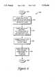
- FIG. 6is a flow diagram illustrating step 108 of FIG. 2, in which the position and orientation of the rotary table 14 and selection template 80 are determined with respect to the origin at base 33 so that these items may be used during a digitization process.
- the determination of the coordinate information for the rotary tableis described first, although the template and table initializations can be performed in any desired order. In addition, depending on the accuracy desired, either of steps 162 and 164 can be omitted from the present process in alternate embodiments.
- Steps 162-165are provided to locate rotary table 14 relative to the probe apparatus 12.
- the processbegins at 160, and in step 162, the position of rotary table 14 is determined and stored on a storage or memory device, such as a device of host computer 18. More specifically, the position of the center of rotary table is determined using stylus 22 of probe apparatus 12.
- a sleeve, aperture, or other receptacleis positioned in the middle of the rotary table into which the stylus can be inserted to provide a precise position of the rotary table 14 with respect to the base of linkage assembly 23. For example, referring to FIG.
- rotating surface 60 of rotary table 14includes a recessed sleeve or divot 170 positioned in the center of rotating surface 60 and able to receive tip 43 of stylus 22. Once stylus 22 is placed in sleeve 170, the probe controller can read and record the angles of sensors 54 of probe apparatus 12.
- next step 164 of FIG. 6multiple configurations of the stylus are read and recorded as the stylus is rotated with the table.
- a shallow divot 172 or similar receptacleis preferably placed near the periphery of rotary table 14.
- the userplaces tip 43 of stylus 22 in the divot 172 and rotates the table while keeping stylus 22 placed in the divot.
- interface 16reads and stores sensor angle values at multiple stylus positions from both sensors 54 of probe apparatus 12 and sensor 174 of the rotary table (described below).
- at least three different sets of anglesare read and stored as coordinates as the stylus is rotated.
- the usercan move the stylus to multiple points on the periphery of the rotating surface 60 by picking up the stylus and moving it to the new points, rather than rotating surface 60 with the stylus.
- step 165the position of the center of the rotary table 14 with respect to base 33 and the orientation of the plane of the surface of turntable 60 with respect to the orientation of the plane of arm base 33 are preferably determined.
- the difference in orientations of the turntable 60 and base 33can be assumed to be zero if both table 14 and probe apparatus 12 rest on a flat surface.
- These features of the rotary tableare derived from the angle values read in steps 162 and 164 using geometrical techniques, as is well known to those skilled in the art.
- the center of the tablecan also be determined just using the data collected in step 164; however, the data from step 162 provides a more accurate determination. Thus, the location and orientation of the rotary table with respect to the base of the probe apparatus is determined.
- steps 162-164can be omitted by coupling the rotary table 14 to base 33 of probe apparatus 12.
- a connecting membercan be coupled to base 33 at one end and to table base 62 at its other end.
- the rotary tablewould thus be at a fixed, known position and orientation with reference to the probe apparatus 12, and the locating process of steps 162-166 would not be necessary.
- calibration factorscan also be determined and stored for the rotary table, similarly to the starting angles for the home position of the probe apparatus as described in FIG. 3a, to compensate for variations in dimensions in individual probe/table apparatuses.
- rotary table 14includes a sensor 174 which is preferably positioned at the center of the table 14 and is coupled to base 62.
- the sensor shaftcan be coupled to rotating surface 60.
- Sensor 174can be an optical encoder as described above or a different type of sensor, such as a potentiometer, resolver, hall effect sensor, etc. Alternatively, sensor 174 can be positioned near the edge of rotating surface 60.
- Sensor 174is operative to sense the rotation of rotating surface 60. For example, if the user rotates the surface 60 by ⁇ degrees in the direction shown by arrow 176 so that object 20 is at a new position (and orientation), sensor 170 detects this amount of rotation and transmits the information to interface 16 and/or host computer 18.
- a coordinate transformationcan be applied to the angle data using the known ⁇ value to derive the new position and orientation of the object.
- Such a coordinate transformationis well known to those skilled in the art. This allows the user to rotate the object to gain easier access to different surfaces on the object and then continue tracing the object with minimal distraction and very little loss in accuracy.
- the coordinate transformationcan be performed by host computer 18 that receives independent data from probe apparatus 12 and rotary table 14. Or, interface 16 can perform the transformation and provide transformed coordinates to host computer 18.
- Rotary table 14preferably is coupled to interface electronics 16 which are positioned within the probe apparatus 12. Probe apparatus 12 thus provides signals from the sensors of probe apparatus 12 as well as the sensor 174 of rotary table 14 to a single I/O port of host computer 18. Alternatively, the interface electronics can be housed in a discrete box that is separate from probe apparatus 12 and rotary table 14, as shown in FIG. 7. Alternatively, interface electronics 16 can be housed within rotary table 14. In yet a different embodiment, rotary table 14 can include sensor interface circuitry only for rotary table 14, and can provide angle information to interface electronics 16.
- rotary tablecan be provided with its own interface electronics that are independently routed to a second I/O port of host computer 18 that is different from the I/O port receiving information from probe apparatus 12.
- Template 80includes selection areas 82, which can include icons, shapes, letters, numbers, words, etc.
- the usermay position tip 43 of stylus 22 within, for example, icon 180, to activate a function of software that host computer 18 is running or a function of probe apparatus 12 or even rotary table 14.
- template 80does not require any separate sensing apparatus such as a computer tablet or the like, since the probe apparatus 12 can be used to uniquely locate selection areas 82 and provide commands based on selections of stylus 22.
- the usercan position the stylus at a top or bottom boundary 182 and a left or right boundary 184.
- the host computerwould thus be informed of the precise location of a planar, rectilinear template 80 within the working volume of probe apparatus 12.
- the styluscan be positioned at three reference points, for example, that are located at the comers of the template.
- the host computercan be provided with predetermined functions that are to be implemented if the stylus is within a specific selection area 82 referenced as a position offset from an edge of template 80. For example, "autotrigger mode" can be activated using the template shown in FIG.
- FIG. 8if stylus tip 43 is first found to be within the template boundaries 182 and 184, and is also found to have an offset within ⁇ x, ⁇ y from the left and top edges (i.e., within selection area 82).
- Selection area 82 examples of FIG. 8include commands to manipulate mesh representation 78, such as "end mesh”, “end line”, “erase mesh”, etc. Many of these commands are described in greater detail with reference to FIG. 11. Other methods can also be used to position template 80 with reference to probe apparatus 12 and to determine functions selected within the template 80. The process of FIG. 6 is then complete at 168.
- FIG. 9is a detailed view of object 20 that is to be traced to develop a mesh representation.
- Object 20has a surface 190 shown with surface lines 192 displayed thereon.
- the usercan contact the surface 190 of object 20 with stylus 22 and trace the stylus along these surface lines 192, as shown by arrow 191.
- surface lines 192need not be actually drawn on object 20; the user simply has to trace stylus 22 generally along the surface 190 following paths similar to lines 192.
- the usercan draw or etch surface lines 192 on surface 190 to help to guide stylus 22 on the object.
- data pointsare sampled along the surface lines by the sensors 54 of probe apparatus 12, as described below.
- the data pointsare then sent from the probe apparatus 12 to host computer 18.
- the datais sent either sent as raw angle data from interface 16, which the host computer converts to coordinates (x, y, z and roll, pitch, yaw); or, the angle data is converted to coordinate values by interface 16 and then sent to computer system 18.
- FIG. 10is an illustration of mesh representation 78 (also referred to as a "mesh") that is developed by host computer 18 using the method of the present invention after a user has traced surface lines 192 of object 20 shown in FIG. 9.
- Mesh representation 78includes contour lines 194 which are computer-generated lines that generally follow corresponding surface lines 192 on object 20 which the user traced.
- Contour lines 194each include a number of points 196 which were provided as angle values or coordinates to host computer 18 from probe apparatus 12. Each point 196 describes a corresponding surface point on surface 190 of object 20.
- pointor “data point” refers to the data, such as angle values or coordinates, that describe the current position and orientation of the stylus 22, while “surface point” refers to the corresponding portion on the surface of the object which is pointed to by the stylus 22.
- Each pointafter being converted from angle data to coordinate data, includes x, y, and z position data as well as roll, pitch and yaw orientation data.
- Computer system 18receives points 196 and connects the points to form contour lines.
- Mesh lines 198are also added to connect the points 196 of one contour line to the points 196 of an adjacent contour line.
- the creation of mesh lines for the present inventionis described in greater detail in the process of FIG. 11.
- Mesh lines 198 and contour lines 194define triangles 199, as described below.
- Mesh representation 78can be manipulated by host computer system 18 in many ways, as is well known by those skilled in the art. For example, mesh representation can be rendered and displayed having color and surface shading to create a realistic-looking 3-D representation; or mesh representation 78 can be rotated, copied, or edited as the user desires using functions of computer system 18.
- FIG. 11is a flow diagram illustrating step 110 of FIG. 2, in which a mesh representation of object 20 is developed by computer system 18 using a preferred method of the present invention.
- the processbegins at 200.
- step 202a start new mesh command is received by host computer system 18 from the user. This command can be entered by the user using standard interface devices or using selection template 80.
- step 204the process checks if the foot pedal 71 is down, i.e. has been activated by the user. In other embodiments, other activation controls can be checked, such as a button on stylus 22, etc. If the foot pedal is not activated, then the process continues to wait at step 204 for the user to activate the foot pedal.
- step 206is implemented, in which the current point pointed to by tip 43 of stylus 22 is input to the host computer system 18 and is added to the current contour line. If this is the first point entered for a line, then that point begins a new contour line.
- next step 208a triangle is created for the current point between the current contour line and the last contour line using the orientation of stylus 22 or other used probe device.
- the created triangleis also preferably displayed in this step, although the triangle need not be displayed in other embodiments.
- This stepis described in greater detail with reference to FIG. 12.
- One of the advantages of the method of the present inventionis that points and triangles are incrementally added to mesh representation 78 and displayed to the user as the user adds each new point when tracing. The user can thus view display screen 76 and quickly determine if a mesh is being created properly during the tracing process, i.e., the user does not have to wait until the entire object is traced before viewing the resulting mesh representation.
- Another advantage of the present inventionis that the orientation of the stylus (or other probe) is used to help create triangles in the mesh. This is described in greater detail below.
- step 210the process checks if auto-trigger mode has been selected by the user.
- Auto-trigger modeallows points to be input to computer system 18 from probe apparatus 12 automatically while the user traces surface lines 192. If auto-trigger mode has been selected by the user (either before the current contour line was begun or during the input of the current line), then step 212 is implemented, in which the process checks whether foot pedal 71 is "up", i.e., deactivated.
- foot pedal 71is "up", i.e., deactivated.
- pointsare automatically input to host computer system 18 from probe apparatus 12 as long as the user continues to activate foot pedal 71 (and the stylus moves a minimum distance, explained below). Once the user releases (deactivates) the foot pedal, points will no longer be automatically entered.
- step 222If the foot pedal is up, then the process continues to step 222, detailed below. If the foot pedal is still down in step 212, the process continues to step 214, where the process checks if the stylus 22 has been traced for the minimum distance.
- a pointis automatically input to computer system 18 when the stylus 22 has been moved a minimum predetermined distance by the user along a surface line. For example, the minimum distance can be set to 0.2 inches. While auto-trigger mode has been selected and the foot pedal is being activated, a point will be input to computer system 18 every 0.2 inches the user moves stylus 22. In alternate embodiments, other criteria can be used to determined when points are entered. For example, a minimum length of time can be specified, such as 2 seconds. Thus, while in auto-trigger mode and foot pedal 71 is being activated, a new point is automatically input to host computer 18 every 2 seconds, regardless of the current stylus position.
- step 214If the stylus 22 has not been moved the minimum distance in step 214, then the process returns to step 212 to check whether the foot pedal is still being activated. In actuality, steps 212 and 214 (and 210) can be checked simultaneously by host computer system 18 as "events" which may occur at any time, as is well known to those skilled in the art. A foot pedal deactivation in step 212 takes precedence over the other checks. Once the probe has been moved the minimum distance in step 214, the process returns to step 206 to add the current point to the current line at the current position of stylus tip 43.
- step 216If auto-trigger mode has not been selected by the user as checked in step 210, then the process checks in step 216 if an "end mesh" command has been entered.
- An end mesh commandindicates that the user is finished entering data and that either the mesh representation is complete or that the user will continue to input data at a later time. Thus, if an end mesh command has been entered, the process is complete at 217. If an end mesh command has not been entered, then, in step 218, the process checks if an "end line” command has been entered by the user. The end line command indicates that the user has finished the current contour line and will enter a new contour line. If an end line command has been entered, the process continues to step 222, detailed below.
- step 220the process checks if the foot pedal is up.
- a pointis entered by activating the foot pedal once and then deactivating it, i.e., pushing down on the foot pedal and releasing it. If the foot pedal has not been released, then a new point cannot be entered, so the process returns to step 216 to check for an end mesh command, end line command, or a foot pedal deactivation. Similar to steps 210, 212 and 214 described above, steps 216, 218 and 220 can preferably be checked simultaneously. Once the foot pedal has been released in step 220, the process returns to step 204 to check for the foot pedal to be activated again to enter a new data point.
- step 222is implemented.
- the mesh representation 78is closed. Depending on what points have been entered on the current contour line, this may cause additional triangles to be created in the mesh. Step 222 is described in greater detail with reference to FIG. 17.
- step 224the process checks if an end mesh command has been received. This is similar to step 216, described above. If an end mesh command is received, then the process is complete at 217. If no end mesh command is received, then it is assumed that the user wishes to enter another contour line, and, in step 226, the last line is set equal to the current line, and a new current line is ready to be received. The process then returns to step 204 to wait for the foot pedal to be activated.
- FIG. 12is a flow diagram illustrating step 208 of FIG. 11, in which a triangle is created and preferably displayed for the current point between the current line and the last line using the orientation of the probe.
- a mesh representation 230as shown in FIG. 13 and additional figures will be referenced.
- Mesh representation 230includes four contour lines: line A-F which includes points A, B, C, D, E, and F; line G-J which includes points G, H, I, and J; line K-P which includes points K, L, M, N, O, and P; and line Q-S which includes points Q, R, and S.
- Mesh linesare shown between the points of each adjacent contour line.
- the method of the present inventionallows the contour lines to be input in any direction, so the lines can be entered, for example, in the order of A-B-C-D-E-F, or in the order of F-E-D-C-B-A.
- the points of a mesh representationare located relative to each other by host computer 18 by examining the (x, y, z) portion of each point. The roll, pitch, yaw portion of each point is used to find the normal vectors, described below.
- step 236the process checks if the current contour line is the first line of the mesh representation. If so, then two possible triangles cannot yet be created and one of the triangles selected (as detailed below), so the process is complete at 235. If the current line is not the first line of the mesh in step 236, then, in step 238, the process checks if the current point is the first point of the current line. Since, in the described method, a triangle cannot be created until the second or later point of the current line is entered, the process is complete at 235 if the current point is the first point. If the current point is not the first point, then, in step 240, the process checks if the current point is the second point of the current line.
- step 242in which the first point of the last line is decided. Since the last line has two end points, one of those end points is chosen as the first point of the last line. This determines the "meshing direction," i.e., the order of points in the last line which are to be connected with the current line. In the preferred embodiment, the closest point on the last line to the current point is chosen as the first point of the last line. It thus is of no significance in which order the user inputted the points on the last line, since the closest point is chosen. In alternate embodiments, other criteria can determine which point of the last line is chosen as the first point.
- the processcan also check if the points of the last line, when examined in the decided meshing direction starting from the chosen first point, follow a path that is approximately in the same direction the points of the current line. If the directions are not the same, the opposite end point of the last line should be chosen as the first point of the last line.
- step 244a variable INDEX is set equal to the first point of the last line. INDEX holds the value(s) (i.e. coordinates or angle values) of a particular point in a contour line.
- step 246is performed, in which one or more triangles are added between the current line and the last line for the current point. This is described in greater detail with reference to FIG. 14.
- step A-Fis first entered and is then considered the last line.
- Point Gis the current point.
- the process of FIG. 12ends after step 238 since point G is the first point of the line.
- point His input and is considered the current point. Since H is the second point of the current line, step 242 decides that point A will be the first point of the last line, since point A is closer to point H than to point F.
- Trianglesare then added between the last line and the current line, as detailed below.
- FIG. 14is a flow diagram illustrating step 246 of FIG. 12, in which triangles are added between current line and the last line for the current point.
- the processbegins at 250.
- step 252the process checks if INDEX is the last point of the last line. If this condition is true, then no more triangles need be added between the current line and last line, and the process is complete at 258. If INDEX is not the last point of the last line, then, in step 254, the process checks if the distance between INDEX and the current point is less than the distance between INDEX+1 and the last point of the current line ("last point"). This step checks the hypotenuses of two possible triangles that can be added using the current point, as explained below.
- FIG. 15ais a diagrammatic illustration providing a portion of mesh 230 of FIG. 13 as an example.
- Contour line A-Fhas been previously entered by the user and is designated the last line.
- Point Gis added as the beginning of a new contour line, and starts the current line.
- Point His then added, and point A is chosen as the first point of the last line A-F.
- two possible trianglescan be created between the current line and the last line: triangle ABG and triangle AHG.
- INDEXhas been set equal to point A
- INDEX+1is the next point after INDEX, i.e., point B
- the last pointis point G.
- the processchecks if the distance between point A (INDEX) and point H (the current point) is less than the distance between point B (INDEX+1) and point G (last point), i.e., if hypotenuse AH is less than hypotenuse BG.
- step 256is implemented, in which the triangle at (INDEX, current point, last point) is added to the mesh representation.
- the points of the triangleare added to a list of triangles for the mesh.
- Step 256also adds a normal vector for the added triangle to the list of triangles. The normal vector is described in greater detail below. For example, as shown in FIG. 15a, this triangle corresponds to triangle AHG. In the example shown, however, this triangle would not be added, since hypotenuse AH is not less than hypotenuse BG.
- step 260the triangle at (INDEX, INDEX+1, last point) is added to the mesh representation.
- This stepis similar to step 256, i.e., the triangle and normal vector are added to the triangle list. As shown in FIG. 15a, this triangle corresponds to triangle ABG. In the example of FIG. 15a, this triangle would be added, the results of which are shown in FIG. 15b.
- INDEXis incremented to the next point on the last line in step 262. For example, INDEX is set equal to point B once triangle ABG is added, and INDEX+1 thus becomes point C.
- step 262the process returns to step 254 to check the hypotenuses for the new INDEX points.
- the processis not complete after step 262 since, if step 254 is false, it indicates that more than one triangle can be added for the current point. Thus, additional triangles are added by checking the conditions of step 254 with the new INDEX point.
- Step 254checks if hypotenuse BH has a smaller length than hypotenuse CG.
- hypotenuse CGhas a smaller length, so triangle BCG is added to the mesh representation, as shown in FIG. 15c.
- INDEXis again incremented, and thus is now point C.
- the processchecks if hypotenuse CH has a smaller length than hypotenuse DG.
- Hypotenuse CHis smaller, so step 256 adds triangle CHG, as shown in FIG. 15d. The process is then complete at 258, so that a new point is eventually input by the user in step 206 of FIG. 11.
- Process 246is then again implemented for new point I as the current point, as shown in FIG. 15d.
- the processchecks if hypotenuse CI has less length than hypotenuse DH. DH has less length, so the triangle CDH is added in step 260 and INDEX is incremented in step 262. As shown in FIG. 15e, triangles are added until the last point J of the current line is input. A new contour line is then begun with the input of points K and L, and the last line is set to line G-J. Triangles continue to be added to mesh representation 230 in a similar fashion.
- a triangleincludes one point from the current contour line, one point from the last contour line, and a third point that is either from the current line or the last line, depending on the distances between the examined hypotenuses.
- step 254can check for different conditions to determine which triangle to add to the mesh representation. For example, the area of triangle (INDEX, current point, last point) can be compared to the area of triangle (INDEX, INDEX+1, last point). The triangle with the smallest area can be added to the mesh. Alternatively, the perimeter distance of the two possible triangles can be compared, where the triangle with the smaller perimeter distance is added to the mesh representation. Other conditions can be checked in other embodiments.
- FIG. 16shows stylus 22 tracing a surface line 192 on object 20.
- a portion of mesh representation 78 that is being developed in host computer 18is also shown superimposed on the corresponding surface portion of object 20.
- Triangles 199are added to the mesh representation 78 as stylus 22 moves.
- a normal vector 270is also determined for each added triangle 199.
- the normal vectoris used by rendering processes and other processes that manipulate a mesh representation to determine which side of a triangle 199 (or other polygon) is facing "outward", i.e. which side of the triangle is the exterior surface of the 3-D object represented by the mesh representation.
- the normal vector 270points outward to show which side of a triangle is the exterior surface. For example, processes can use the normal vector information to provide shadows and shading on a rendered object from a virtual light source.
- the normal vector 270 for a triangleis quickly and easily determined.
- the x, y and z coordinates of the points of a triangle 199define the position of the triangle in space, but do not define the orientation of the triangle.
- the position of the normal vectoris known, but not the orientation of the vector.
- the orientation of the stylusis known and recorded in the points as well as the position.
- the orientation of a trianglecan thus be determined from the orientation coordinates of roll, pitch, and yaw included in each point.
- the orientation of a normal vectoris defined as opposite to the orientation of the stylus at the time when the stylus is adding the points of the triangle.
- the normal vectorcan be defined as the same orientation as the stylus.
- the orientation coordinates of 1-3 points of triangle 199can be examined to determine the normal vector; since all of these points were traced by the user from the same side of the object (the exterior side), any of the points can be used to determine this direction.
- FIG. 17is a flow diagram illustrating step 222 of FIG. 11, in which a close mesh process is implemented.
- the processbegins at 274.
- step 276the process checks if INDEX is the last point of the last line. If so, then the process is complete at 278. If INDEX is not the last point of the last line, then, in step 280, a triangle (INDEX, INDEX+1, current point) is added to the mesh representation and the triangle list with a normal vector, similar to steps 256 and 260 described with reference to FIG. 14.
- INDEXis incremented to the next point of the last line, and the process returns to step 276 to check if INDEX is the last point of the last line. An example of this process is described with reference to FIGS. 18a and 18b.
- FIG. 18ais a diagrammatic illustration showing a portion of a mesh representation 284 which makes use of the close mesh process of FIG. 17.
- Line A-Fis the last line
- line G-Iis the current line
- point Cis INDEX.
- step 280 of FIG. 17adds the triangle at (INDEX, INDEX+1, current point), which in this example is triangle CDI.
- INDEXis then incremented in step 282.
- triangle DEIis added, and in the final iteration, triangle EFI is added.
- INDEXpoint F
- the final mesh representation 284is shown in FIG. 18b.
- FIG. 19is a flow diagram illustrating a preferred assembly process 300 for assembling the precision linkages and joints of probe apparatus 12 or a similar device having such linkages and joints.
- the processbegins at 302.
- joint fixturesare provided at a precise distance apart from each other and within a precise angle of each other. Such joint fixtures are adapted to secure a joint in place, and are well known to those skilled in the art.
- the precise distanceis the desired length of a linkage in the linkage assembly.
- the precise angleis the desired angle or offset from a linear position between the joints.
- a joint-linkage assemblyis connected to the fixtures such that the joints in the assembly are positioned the precise distance and angle apart.
- a joint linkage assemblycan be connected that includes joint members 24, 26, and 28 and linkages 30 and 32 as shown in FIG. 1.
- the linkagesare preferably loosely connected to the joints so that the joint members can be adjusted to fit into the joint fixtures.
- the linkagesare bonded to the joint members at the precise distance and angle.
- the bonding processprovides negligible residual stress, such that when the joint members are removed from the joint fixtures, they will not deflect or flex.
- FIG. 20is a schematic diagram showing joint fixtures 312a and 312b.
- the joint fixturesare provided a precise distance d apart from one another, where d is a desired length for a linkage in the joint-linkage assembly.
- the fixturesare also provided a precise angle ⁇ offset from each other, if such an offset is desired.
- the joint fixturescan be coupled together by member 313 to provide a precise position of the fixtures relative to each other.
- Joint-linkage assembly 314is placed in the fixtures such that each joint member 316a and 316b is in a fixture and secured in place. After the joint members 316 have been secured, linkage 318 is bonded in place.
- the describedthus provides a simple, inexpensive method for assembling joints and linkages with a high degree of accuracy.
- Linkage 318which is assembled by process 300 and linkages 30 and 32 of the probe apparatus of FIG. 1 are made of graphite in the preferred embodiment of the present invention.
- Graphiteallows linkages to be have a lighter weight, stiffer structure, and be far more temperature stable than linkages of the prior art, which are typically made from aluminum.
- linkages made of graphiteBy using linkages made of graphite, a lightweight, easy to use and precise instrument that retains its precision over time is the result.
- graphiteworks well in the bonding assembly process described in FIG. 19, since graphite linkages are not as well adapted for other fastening processes. For example, graphite is not well suited to be screwed into joint members or similarly fastened with rotary or linear tension.
- FIG. 21a and 21billustrate a front view and a side view, respectively, of a multistage stop joint 320 for the present invention.
- the multistage stop of the present inventionallows a linkage or probe of probe apparatus 12, such as stylus 22, to be moved greater than 360 degrees about an axis provided by the multistage stop joint. This allows a greater freedom of movement for the user when tracing object 20 with the probe apparatus.
- Joint 320includes a first member 322 of joint 320 and a second member 324 of joint 320.
- first member 322is coupled to stylus 22; first member can be coupled to other linkages 30, 32, or 34 of probe apparatus 12 as well.
- a usercan rotate stylus 22 about an axis A1 by rotating first member 322 about axis A1.
- Second member 324typically stays fixed in place on linkage assembly 23.
- FIG. 21bshows second member 324 coupled to linkage 30.
- first member 322can remain fixed while second member 324 is rotated about axis A1.
- First member 322includes a first stop 326 and second member includes a second stop 328.
- a sensor 336can be positioned in second member 324 which is coupled to first member 322 via shaft 337.
- a middle member 330is preferably coupled to first member 322.
- middle member 330can be coupled to second member 324.
- Middle member 326rotates about axis A1 independently of first member 322 and second member 324 and includes a third stop 332.
- first stop 326When first member 322 is rotated about axis A1 in, for example, the counterclockwise direction indicated by arrow 334, first stop 326 eventually impacts third stop 332. If third stop 322 has no obstructions in its path, the middle member 330 is rotated in conjunction first member 322 in the direction of arrow 334. Once third stop impacts second stop 328, however, no further rotation of first member 322 and middle member 330 is allowed, since second member 324 is fixed in place. This configuration of middle member impacting second stop 328 is shown in FIG. 21a.
- First member 322can be rotated in the direction opposite to arrow 334 (clockwise) from the position shown in FIG. 21a. First member 322 is allowed to rotate clockwise almost 360 degrees before impacting third guide 322. Both first member 322 and middle member 330 are then rotated in conjunction in the clockwise direction. Again, the middle member 330 is allowed almost 360 degrees of rotation before impacting second guide 324, which obstructs any further rotation.
- first member 322is allowed almost 720 degrees of rotation (i.e., two full rotations) in the direction opposite to arrow 334 from the position shown in FIG. 21a until second stop is impacted.
- the multistage stop joint 320thus allows a greater range of motion to stylus 22 and any other linkages that are coupled to similar joints.
- the stylus 22is still limited in its movement by stops, however, which is important in that a wire bundle that is routed through joint 320 does not become overly stressed or twisted (which would occur if joint 320 had no stops at all).
- the probe apparatus 12can be used to control objects, such as a virtual stylus, in a virtual reality simulation.
Landscapes
- Engineering & Computer Science (AREA)
- General Engineering & Computer Science (AREA)
- Physics & Mathematics (AREA)
- General Physics & Mathematics (AREA)
- Theoretical Computer Science (AREA)
- Human Computer Interaction (AREA)
- Robotics (AREA)
- Mechanical Engineering (AREA)
- Automation & Control Theory (AREA)
- Length Measuring Devices With Unspecified Measuring Means (AREA)
- A Measuring Device Byusing Mechanical Method (AREA)
Abstract
Description
Claims (48)
Priority Applications (14)
| Application Number | Priority Date | Filing Date | Title |
|---|---|---|---|
| US08/512,084US5724264A (en) | 1993-07-16 | 1995-08-07 | Method and apparatus for tracking the position and orientation of a stylus and for digitizing a 3-D object |
| CA002228587ACA2228587C (en) | 1995-08-07 | 1996-07-29 | Method and apparatus for tracking position and orientation of a stylus and for digitizing a 3-d object |
| EP96926179AEP0843808B1 (en) | 1995-08-07 | 1996-07-29 | Method for zeroing transducers of a probe apparatus of a 3-d coordinate measuring system |
| ES96926179TES2213181T3 (en) | 1995-08-07 | 1996-07-29 | REPLACEMENT PROCEDURE TO ZERO OF THE DEVICES OF AN APPLIANCE WITH PROBE OF A 3-D COORDINATE MEASUREMENT SYSTEM. |
| DE69631144TDE69631144T2 (en) | 1995-08-07 | 1996-07-29 | METHOD FOR ZERO-SETTING THE RECEIVERS OF A PROBE HEAD DEVICE OF A 3-D COORDINATE MEASURING DEVICE |
| PCT/US1996/012448WO1997006410A1 (en) | 1995-08-07 | 1996-07-29 | Method and apparatus for tracking position and orientation of a stylus and for digitizing a 3-d object |
| DE69638212TDE69638212D1 (en) | 1995-08-07 | 1996-07-29 | Method and device for position and orientation measurement of a probe and for digitizing a 3-D object |
| EP03028886AEP1424538B1 (en) | 1995-08-07 | 1996-07-29 | Method and apparatus for tracking position and orientation of a stylus and for digitizing a 3-D object |
| US08/739,454US6134506A (en) | 1995-08-07 | 1996-10-29 | Method and apparatus for tracking the position and orientation of a stylus and for digitizing a 3-D object |
| US08/741,190US6078876A (en) | 1995-08-07 | 1996-10-29 | Method and apparatus for tracking the position and orientation of a stylus and for digitizing a 3-D object |
| US08/744,725US6015473A (en) | 1995-08-07 | 1996-11-01 | Method for producing a precision 3-D measuring apparatus |
| US09/212,075US6125337A (en) | 1993-07-16 | 1998-12-15 | Probe apparatus and method for tracking the position and orientation of a stylus and controlling a cursor |
| US09/687,923US6697748B1 (en) | 1995-08-07 | 2000-10-13 | Digitizing system and rotary table for determining 3-D geometry of an object |
| US10/781,801US7054775B2 (en) | 1995-08-07 | 2004-02-20 | Digitizing system and rotary table for determining 3-D geometry of an object |
Applications Claiming Priority (3)
| Application Number | Priority Date | Filing Date | Title |
|---|---|---|---|
| US9297493A | 1993-07-16 | 1993-07-16 | |
| US08/461,170US5576727A (en) | 1993-07-16 | 1995-06-05 | Electromechanical human-computer interface with force feedback |
| US08/512,084US5724264A (en) | 1993-07-16 | 1995-08-07 | Method and apparatus for tracking the position and orientation of a stylus and for digitizing a 3-D object |
Related Parent Applications (2)
| Application Number | Title | Priority Date | Filing Date |
|---|---|---|---|
| US9297493AContinuation | 1993-07-16 | 1993-07-16 | |
| US08/461,170Continuation-In-PartUS5576727A (en) | 1993-07-16 | 1995-06-05 | Electromechanical human-computer interface with force feedback |
Related Child Applications (3)
| Application Number | Title | Priority Date | Filing Date |
|---|---|---|---|
| US08/741,190DivisionUS6078876A (en) | 1995-08-07 | 1996-10-29 | Method and apparatus for tracking the position and orientation of a stylus and for digitizing a 3-D object |
| US08/739,454DivisionUS6134506A (en) | 1993-07-16 | 1996-10-29 | Method and apparatus for tracking the position and orientation of a stylus and for digitizing a 3-D object |
| US08/744,725DivisionUS6015473A (en) | 1995-08-07 | 1996-11-01 | Method for producing a precision 3-D measuring apparatus |
Publications (1)
| Publication Number | Publication Date |
|---|---|
| US5724264Atrue US5724264A (en) | 1998-03-03 |
Family
ID=24037603
Family Applications (5)
| Application Number | Title | Priority Date | Filing Date |
|---|---|---|---|
| US08/512,084Expired - LifetimeUS5724264A (en) | 1993-07-16 | 1995-08-07 | Method and apparatus for tracking the position and orientation of a stylus and for digitizing a 3-D object |
| US08/739,454Expired - LifetimeUS6134506A (en) | 1993-07-16 | 1996-10-29 | Method and apparatus for tracking the position and orientation of a stylus and for digitizing a 3-D object |
| US08/741,190Expired - LifetimeUS6078876A (en) | 1995-08-07 | 1996-10-29 | Method and apparatus for tracking the position and orientation of a stylus and for digitizing a 3-D object |
| US08/744,725Expired - LifetimeUS6015473A (en) | 1995-08-07 | 1996-11-01 | Method for producing a precision 3-D measuring apparatus |
| US09/212,075Expired - LifetimeUS6125337A (en) | 1993-07-16 | 1998-12-15 | Probe apparatus and method for tracking the position and orientation of a stylus and controlling a cursor |
Family Applications After (4)
| Application Number | Title | Priority Date | Filing Date |
|---|---|---|---|
| US08/739,454Expired - LifetimeUS6134506A (en) | 1993-07-16 | 1996-10-29 | Method and apparatus for tracking the position and orientation of a stylus and for digitizing a 3-D object |
| US08/741,190Expired - LifetimeUS6078876A (en) | 1995-08-07 | 1996-10-29 | Method and apparatus for tracking the position and orientation of a stylus and for digitizing a 3-D object |
| US08/744,725Expired - LifetimeUS6015473A (en) | 1995-08-07 | 1996-11-01 | Method for producing a precision 3-D measuring apparatus |
| US09/212,075Expired - LifetimeUS6125337A (en) | 1993-07-16 | 1998-12-15 | Probe apparatus and method for tracking the position and orientation of a stylus and controlling a cursor |
Country Status (6)
| Country | Link |
|---|---|
| US (5) | US5724264A (en) |
| EP (2) | EP1424538B1 (en) |
| CA (1) | CA2228587C (en) |
| DE (2) | DE69631144T2 (en) |
| ES (1) | ES2213181T3 (en) |
| WO (1) | WO1997006410A1 (en) |
Cited By (263)
| Publication number | Priority date | Publication date | Assignee | Title |
|---|---|---|---|---|
| US5872438A (en)* | 1992-12-02 | 1999-02-16 | Cybernet Systems Corporation | Whole-body kinesthetic display |
| US5898599A (en) | 1993-10-01 | 1999-04-27 | Massachusetts Institute Of Technology | Force reflecting haptic interface |
| US5953687A (en)* | 1997-08-18 | 1999-09-14 | Giddings & Lewis, Inc. | Method and apparatus for displaying active probe tip status of a coordinate measuring machine |
| GB2339370A (en)* | 1998-07-08 | 2000-01-19 | Faro Tech Inc | Moveable articulated arm for a coordinate measuring machine with position transducers connected to a controller via a serial network |
| WO1999007200A3 (en)* | 1997-08-08 | 2000-04-06 | Cimplus Inc | System for continuous motion digitalprobe routing |
| US6064918A (en)* | 1997-01-31 | 2000-05-16 | Komatsu Ltd. | Anti-interference device for construction machine |
| WO2000028393A1 (en)* | 1998-11-05 | 2000-05-18 | Imcs, Inc. | Visual cnc program for generating machining parts |
| US6067077A (en)* | 1998-04-10 | 2000-05-23 | Immersion Corporation | Position sensing for force feedback devices |
| US6073056A (en)* | 1997-04-08 | 2000-06-06 | Larry J. Winget | Method and system for building a data model of a physical part in a data format useful for and reproduction of the part |
| US6084587A (en)* | 1996-08-02 | 2000-07-04 | Sensable Technologies, Inc. | Method and apparatus for generating and interfacing with a haptic virtual reality environment |
| US6106301A (en)* | 1996-09-04 | 2000-08-22 | Ht Medical Systems, Inc. | Interventional radiology interface apparatus and method |
| US6112133A (en)* | 1998-02-27 | 2000-08-29 | Imcs, Inc. | Visual system and method for generating a CNC program for machining parts with planar and curvilinear surfaces |
| US6111577A (en)* | 1996-04-04 | 2000-08-29 | Massachusetts Institute Of Technology | Method and apparatus for determining forces to be applied to a user through a haptic interface |
| US6125337A (en) | 1993-07-16 | 2000-09-26 | Microscribe, Llc | Probe apparatus and method for tracking the position and orientation of a stylus and controlling a cursor |
| WO2000073731A1 (en)* | 1999-05-28 | 2000-12-07 | Taylor Hobson Limited | Movement control by a metrological instrument |
| US6191796B1 (en) | 1998-01-21 | 2001-02-20 | Sensable Technologies, Inc. | Method and apparatus for generating and interfacing with rigid and deformable surfaces in a haptic virtual reality environment |
| US6195618B1 (en) | 1998-10-15 | 2001-02-27 | Microscribe, Llc | Component position verification using a probe apparatus |
| EP1108975A1 (en)* | 1999-12-18 | 2001-06-20 | Dr.Ing. h.c.F. Porsche Aktiengesellschaft | Measuring device for assemblies, in particular for assemblies of a car body |
| US6266551B1 (en)* | 1996-02-15 | 2001-07-24 | Biosense, Inc. | Catheter calibration and usage monitoring system |
| US20020005864A1 (en)* | 2000-04-28 | 2002-01-17 | Texas Tech University | Haptic virtual environments |
| US6366831B1 (en) | 1993-02-23 | 2002-04-02 | Faro Technologies Inc. | Coordinate measurement machine with articulated arm and software interface |
| US20020072814A1 (en)* | 1991-10-24 | 2002-06-13 | Immersion Corporation | Interface device with tactile responsiveness |
| US20020084996A1 (en)* | 2000-04-28 | 2002-07-04 | Texas Tech University | Development of stereoscopic-haptic virtual environments |
| US6417638B1 (en) | 1998-07-17 | 2002-07-09 | Sensable Technologies, Inc. | Force reflecting haptic interface |
| US20020089500A1 (en)* | 2001-01-08 | 2002-07-11 | Jennings Ralph E. | Systems and methods for three-dimensional modeling |
| US6421048B1 (en) | 1998-07-17 | 2002-07-16 | Sensable Technologies, Inc. | Systems and methods for interacting with virtual objects in a haptic virtual reality environment |
| US6424877B1 (en)* | 1997-04-04 | 2002-07-23 | Minolta Co., Ltd. | Reproduction apparatus |
| US6470302B1 (en) | 1998-01-28 | 2002-10-22 | Immersion Medical, Inc. | Interface device and method for interfacing instruments to vascular access simulation systems |
| GB2375026A (en)* | 1998-07-08 | 2002-10-30 | Faro Tech Inc | Moveable articulated arm for coordinate measuring machine with position transducers connected to a controller via a serial network |
| WO2002051053A3 (en)* | 2000-12-18 | 2002-12-05 | Wireless Valley Comm Inc | Textual and graphical demarcation of location, and interpretation of measurements |
| US6522993B1 (en)* | 2001-09-14 | 2003-02-18 | General Electric Company | Method and system for marking surface deviations on a three dimensional surface |
| US6545661B1 (en) | 1999-06-21 | 2003-04-08 | Midway Amusement Games, Llc | Video game system having a control unit with an accelerometer for controlling a video game |
| US6552722B1 (en) | 1998-07-17 | 2003-04-22 | Sensable Technologies, Inc. | Systems and methods for sculpting virtual objects in a haptic virtual reality environment |
| US6565497B1 (en)* | 2000-06-23 | 2003-05-20 | Yamazaki Mazak Kabushiki Kaisha | Complex machining machine tool |
| US6612044B2 (en)* | 2000-02-01 | 2003-09-02 | Faro Technologies, Inc. | Method, system and storage medium for providing an executable program to a coordinate measurement system |
| US20030167647A1 (en)* | 2002-02-14 | 2003-09-11 | Simon Raab | Portable coordinate measurement machine |
| US20030179097A1 (en)* | 2001-02-02 | 2003-09-25 | David Collingwood | Machine tool probe |
| US6650338B1 (en) | 1998-11-24 | 2003-11-18 | Interval Research Corporation | Haptic interaction with video and image data |
| US6671651B2 (en) | 2002-04-26 | 2003-12-30 | Sensable Technologies, Inc. | 3-D selection and manipulation with a multiple dimension haptic interface |
| US20040048230A1 (en)* | 1996-09-04 | 2004-03-11 | Ht Medical Systems, Inc. | Interface device and method for interfacing instruments to medical procedure simulation systems |
| US20040066369A1 (en)* | 1994-07-14 | 2004-04-08 | Rosenberg Louis B. | Physically realistic computer simulation of medical procedures |
| US20040076940A1 (en)* | 1998-01-28 | 2004-04-22 | Immersion Medical, Inc. | Interface device and method for interfacing instruments to medical procedure simulation systems |
| US6738516B1 (en) | 1998-06-18 | 2004-05-18 | Minolta Co., Ltd. | Monitor display apparatus |
| USD490830S1 (en) | 2002-02-14 | 2004-06-01 | Faro Technologies, Inc. | Probe for a portable coordinate measurement machine |
| EP1301754A4 (en)* | 2000-05-31 | 2004-06-02 | Unova Ind Automation Sys Inc | Method and device for calibrating rotary axis |
| US20040103547A1 (en)* | 2002-02-14 | 2004-06-03 | Simon Raab | Portable coordinate measurement machine |
| USD491210S1 (en) | 2003-02-13 | 2004-06-08 | Faro Technologies, Inc. | Probe for a portable coordinate measurement machine |
| US20040111908A1 (en)* | 2002-02-14 | 2004-06-17 | Simon Raab | Method for improving measurement accuracy of a protable coordinate measurement machine |
| US6796048B2 (en) | 2001-02-01 | 2004-09-28 | Faro Technologies, Inc. | Method, system and storage medium for providing a tool kit for a coordinate measurement system |
| USD496595S1 (en) | 2002-02-14 | 2004-09-28 | Faro Technologies, Inc. | Portable coordinate measurement machine portion |
| USD497815S1 (en) | 2002-02-14 | 2004-11-02 | Faro Technologies, Inc. | Portable coordinate measurement machine portion |
| US20040267379A1 (en)* | 2003-04-18 | 2004-12-30 | Stmicroelectronics S.R.L. | Device for measuring the relative angular position of two bodies with respect to a point, and articular prosthesis provided therewith |
| US6839663B1 (en) | 1999-09-30 | 2005-01-04 | Texas Tech University | Haptic rendering of volumetric soft-bodies objects |
| US20050016008A1 (en)* | 2002-02-14 | 2005-01-27 | Simon Raab | Method for providing sensory feedback to the operator of a portable measurement machine |
| US20050017454A1 (en)* | 2003-06-09 | 2005-01-27 | Shoichi Endo | Interactive gaming systems with haptic feedback |
| US6863536B1 (en) | 1998-01-26 | 2005-03-08 | Simbionix Ltd. | Endoscopic tutorial system with a bleeding complication |
| US6867770B2 (en) | 2000-12-14 | 2005-03-15 | Sensable Technologies, Inc. | Systems and methods for voxel warping |
| US20050088408A1 (en)* | 1999-05-11 | 2005-04-28 | Braun Adam C. | Method and apparatus for compensating for position slip in interface devices |
| US20050093874A1 (en)* | 2003-10-30 | 2005-05-05 | Sensable Technologies, Inc. | Apparatus and methods for texture mapping |
| US20050093821A1 (en)* | 2003-10-30 | 2005-05-05 | Sensable Technologies, Inc. | Force reflecting haptic interface |
| USD505144S1 (en)* | 2002-02-14 | 2005-05-17 | Faro Technologies, Inc. | Laser scanner for a portable coordinate measurement machine |
| US20050122242A1 (en)* | 2001-12-21 | 2005-06-09 | Kabushiki Kaisha Yaskawa Denki | Absolute encoder and absolute value signal generation method |
| US20050128210A1 (en)* | 2003-12-10 | 2005-06-16 | Sensable Technologies, Inc. | Haptic graphical user interface for adjusting mapped texture |
| US20050128211A1 (en)* | 2003-12-10 | 2005-06-16 | Sensable Technologies, Inc. | Apparatus and methods for wrapping texture onto the surface of a virtual object |
| US20050134562A1 (en)* | 2003-12-22 | 2005-06-23 | Grant Danny A. | System and method for controlling haptic devices having multiple operational modes |
| US20050154481A1 (en)* | 2004-01-13 | 2005-07-14 | Sensable Technologies, Inc. | Apparatus and methods for modifying a model of an object to enforce compliance with a manufacturing constraint |
| WO2004034241A3 (en)* | 2002-10-09 | 2005-07-28 | Raphael Bachmann | Rapid input device |
| US20050162804A1 (en)* | 2001-06-27 | 2005-07-28 | Boronkay Allen R. | Position sensor with resistive element |
| US20050168476A1 (en)* | 2003-10-30 | 2005-08-04 | Sensable Technologies, Inc. | Apparatus and methods for stenciling an image |
| USD510739S1 (en) | 2003-10-30 | 2005-10-18 | Sensable Technologies, Inc. | Computer interface |
| US20050237581A1 (en)* | 2004-04-21 | 2005-10-27 | Knighton Mark S | Hand held portable three dimensional scanner |
| US6985133B1 (en) | 1998-07-17 | 2006-01-10 | Sensable Technologies, Inc. | Force reflecting haptic interface |
| US20060016086A1 (en)* | 2002-02-14 | 2006-01-26 | Simon Raab | Portable coordinate measurement machine |
| US7006084B1 (en) | 2000-09-26 | 2006-02-28 | Faro Technologies, Inc. | Method and system for computer aided manufacturing measurement analysis |
| US20060069536A1 (en)* | 2004-09-28 | 2006-03-30 | Anton Butsev | Ultrasound simulation apparatus and method |
| US7056123B2 (en)* | 2001-07-16 | 2006-06-06 | Immersion Corporation | Interface apparatus with cable-driven force feedback and grounded actuators |
| US20060129349A1 (en)* | 2002-02-14 | 2006-06-15 | Simon Raab | Portable coordinate measurement machine with integrated line laser scanner |
| US20060161621A1 (en)* | 2005-01-15 | 2006-07-20 | Outland Research, Llc | System, method and computer program product for collaboration and synchronization of media content on a plurality of media players |
| US20060167576A1 (en)* | 2005-01-27 | 2006-07-27 | Outland Research, L.L.C. | System, method and computer program product for automatically selecting, suggesting and playing music media files |
| US20060167943A1 (en)* | 2005-01-27 | 2006-07-27 | Outland Research, L.L.C. | System, method and computer program product for rejecting or deferring the playing of a media file retrieved by an automated process |
| US20060173556A1 (en)* | 2005-02-01 | 2006-08-03 | Outland Research,. Llc | Methods and apparatus for using user gender and/or age group to improve the organization of documents retrieved in response to a search query |
| US20060173828A1 (en)* | 2005-02-01 | 2006-08-03 | Outland Research, Llc | Methods and apparatus for using personal background data to improve the organization of documents retrieved in response to a search query |
| US20060179044A1 (en)* | 2005-02-04 | 2006-08-10 | Outland Research, Llc | Methods and apparatus for using life-context of a user to improve the organization of documents retrieved in response to a search query from that user |
| US20060179056A1 (en)* | 2005-10-12 | 2006-08-10 | Outland Research | Enhanced storage and retrieval of spatially associated information |
| US20060186197A1 (en)* | 2005-06-16 | 2006-08-24 | Outland Research | Method and apparatus for wireless customer interaction with the attendants working in a restaurant |
| US20060190823A1 (en)* | 2001-05-04 | 2006-08-24 | Immersion Corporation | Haptic interface for palpation simulation |
| US20060194180A1 (en)* | 1996-09-06 | 2006-08-31 | Bevirt Joeben | Hemispherical high bandwidth mechanical interface for computer systems |
| US20060195361A1 (en)* | 2005-10-01 | 2006-08-31 | Outland Research | Location-based demographic profiling system and method of use |
| US20060223637A1 (en)* | 2005-03-31 | 2006-10-05 | Outland Research, Llc | Video game system combining gaming simulation with remote robot control and remote robot feedback |
| US20060223635A1 (en)* | 2005-04-04 | 2006-10-05 | Outland Research | method and apparatus for an on-screen/off-screen first person gaming experience |
| US20060227047A1 (en)* | 2005-12-13 | 2006-10-12 | Outland Research | Meeting locator system and method of using the same |
| US20060229058A1 (en)* | 2005-10-29 | 2006-10-12 | Outland Research | Real-time person-to-person communication using geospatial addressing |
| US20060241864A1 (en)* | 2005-04-22 | 2006-10-26 | Outland Research, Llc | Method and apparatus for point-and-send data transfer within an ubiquitous computing environment |
| US20060253210A1 (en)* | 2005-03-26 | 2006-11-09 | Outland Research, Llc | Intelligent Pace-Setting Portable Media Player |
| US20060256007A1 (en)* | 2005-05-13 | 2006-11-16 | Outland Research, Llc | Triangulation method and apparatus for targeting and accessing spatially associated information |
| US20060256008A1 (en)* | 2005-05-13 | 2006-11-16 | Outland Research, Llc | Pointing interface for person-to-person information exchange |
| US20060259574A1 (en)* | 2005-05-13 | 2006-11-16 | Outland Research, Llc | Method and apparatus for accessing spatially associated information |
| US20060271286A1 (en)* | 2005-05-27 | 2006-11-30 | Outland Research, Llc | Image-enhanced vehicle navigation systems and methods |
| US20060267949A1 (en)* | 1999-12-07 | 2006-11-30 | Rosenberg Louis B | Haptic feedback using a keyboard device |
| US20060283279A1 (en)* | 2002-04-03 | 2006-12-21 | Levin Michael D | Haptic control devices |
| US20060288074A1 (en)* | 2005-09-09 | 2006-12-21 | Outland Research, Llc | System, Method and Computer Program Product for Collaborative Broadcast Media |
| WO2006110489A3 (en)* | 2005-04-08 | 2007-01-04 | Univ Utah Res Found | Rapid prototyping of microstructures using a cutting plotter |
| US20070052674A1 (en)* | 1997-12-03 | 2007-03-08 | Culver Craig F | Tactile feedback interface device including display screen |
| US20070075127A1 (en)* | 2005-12-21 | 2007-04-05 | Outland Research, Llc | Orientation-based power conservation for portable media devices |
| US20070083323A1 (en)* | 2005-10-07 | 2007-04-12 | Outland Research | Personal cuing for spatially associated information |
| US20070103437A1 (en)* | 2005-10-26 | 2007-05-10 | Outland Research, Llc | Haptic metering for minimally invasive medical procedures |
| US7225404B1 (en) | 1996-04-04 | 2007-05-29 | Massachusetts Institute Of Technology | Method and apparatus for determining forces to be applied to a user through a haptic interface |
| US20070129888A1 (en)* | 2005-12-05 | 2007-06-07 | Outland Research | Spatially associated personal reminder system and method |
| US20070125852A1 (en)* | 2005-10-07 | 2007-06-07 | Outland Research, Llc | Shake responsive portable media player |
| US20070150188A1 (en)* | 2005-05-27 | 2007-06-28 | Outland Research, Llc | First-person video-based travel planning system |
| US20070265527A1 (en)* | 2006-05-11 | 2007-11-15 | Richard Wohlgemuth | Medical position determination using redundant position detection means and priority weighting for the position detection means |
| US20070276870A1 (en)* | 2005-01-27 | 2007-11-29 | Outland Research, Llc | Method and apparatus for intelligent media selection using age and/or gender |
| US20070294045A1 (en)* | 2002-02-14 | 2007-12-20 | Faro Technologies, Inc. | Portable coordinate measurement machine with integrated line laser scanner |
| US20080032719A1 (en)* | 2005-10-01 | 2008-02-07 | Outland Research, Llc | Centralized establishment-based tracking and messaging service |
| US20080032723A1 (en)* | 2005-09-23 | 2008-02-07 | Outland Research, Llc | Social musical media rating system and method for localized establishments |
| US7444751B1 (en)* | 2007-09-28 | 2008-11-04 | Electro-Sensors, Inc. | Linear distance measurement by non-driven arm |
| JP2008544244A (en)* | 2005-06-15 | 2008-12-04 | レニショウ パブリック リミテッド カンパニー | Contact probe having direction change detection means |
| US20090018808A1 (en)* | 2007-01-16 | 2009-01-15 | Simbionix Ltd. | Preoperative Surgical Simulation |
| US7519537B2 (en) | 2005-07-19 | 2009-04-14 | Outland Research, Llc | Method and apparatus for a verbo-manual gesture interface |
| US20090106994A1 (en)* | 2007-10-31 | 2009-04-30 | Daniel Gomez | Portable Metrology Device |
| US20090228169A1 (en)* | 2008-03-10 | 2009-09-10 | Westline Sarl | Automatic method and system for the calibration of earthworking machines |
| US20090225024A1 (en)* | 2008-03-06 | 2009-09-10 | Immersion Corporation | Determining Location And Orientation Of An Object Positioned On A Surface |
| US20090231336A1 (en)* | 2005-11-17 | 2009-09-17 | Centertrak, Llc | System and method for the digital specification of head shape data for use in developing custom hair pieces |
| US20090318931A1 (en)* | 2003-06-09 | 2009-12-24 | OrthAlign, Inc. | Surgical orientation device and method |
| US7659995B2 (en) | 2000-09-13 | 2010-02-09 | NextPat, Ltd. | Digitizer using plural capture methods to image features of 3-D objects |
| US20100063508A1 (en)* | 2008-07-24 | 2010-03-11 | OrthAlign, Inc. | Systems and methods for joint replacement |
| US20100069941A1 (en)* | 2008-09-15 | 2010-03-18 | Immersion Medical | Systems and Methods For Sensing Hand Motion By Measuring Remote Displacement |
| US20100104162A1 (en)* | 2008-10-23 | 2010-04-29 | Immersion Corporation | Systems And Methods For Ultrasound Simulation Using Depth Peeling |
| US20100161094A1 (en)* | 2008-12-19 | 2010-06-24 | Phillip John Crothers | Conforming components using reverse engineering |
| US20100161100A1 (en)* | 2008-12-19 | 2010-06-24 | Phillip John Crothers | Component repair using reverse engineering |
| US7755602B2 (en) | 1995-11-30 | 2010-07-13 | Immersion Corporation | Tactile feedback man-machine interface device |
| US7765182B2 (en) | 1996-05-21 | 2010-07-27 | Immersion Corporation | Haptic authoring |
| US20100249693A1 (en)* | 2009-03-31 | 2010-09-30 | Abbott Medical Optics Inc. | Cassette capture mechanism |
| US7815436B2 (en) | 1996-09-04 | 2010-10-19 | Immersion Corporation | Surgical simulation interface device and method |
| US20100305928A1 (en)* | 2009-05-28 | 2010-12-02 | Immersion Corporation | Systems and Methods For Editing A Model Of A Physical System For A Simulation |
| US7850456B2 (en) | 2003-07-15 | 2010-12-14 | Simbionix Ltd. | Surgical simulation device, system and method |
| USRE42082E1 (en) | 2002-02-14 | 2011-02-01 | Faro Technologies, Inc. | Method and apparatus for improving measurement accuracy of a portable coordinate measurement machine |
| US7881896B2 (en) | 2002-02-14 | 2011-02-01 | Faro Technologies, Inc. | Portable coordinate measurement machine with integrated line laser scanner |
| US20110092887A1 (en)* | 2008-11-07 | 2011-04-21 | Abbott Medical Optics Inc. | Method for programming foot pedal settings and controlling performance through foot pedal variation |
| US20110098721A1 (en)* | 2008-11-07 | 2011-04-28 | Abbott Medical Optics Inc. | Adjustable foot pedal control for ophthalmic surgery |
| US20110170534A1 (en)* | 2010-01-11 | 2011-07-14 | Faro Technologies, Inc. | Method and apparatus for synchronizing measurements taken by multiple metrology devices |
| US20110175745A1 (en)* | 2010-01-20 | 2011-07-21 | Faro Technologies, Inc. | Embedded arm strain sensors |
| US20110178764A1 (en)* | 2010-01-20 | 2011-07-21 | Faro Technologies, Inc. | Portable Articulated Arm Coordinate Measuring Machine with Multi-Bus Arm Technology |
| US20110176148A1 (en)* | 2010-01-20 | 2011-07-21 | Faro Technologies, Inc. | Coordinate measuring machine having an illuminated probe end and method of operation |
| US7995834B1 (en) | 2006-01-20 | 2011-08-09 | Nextengine, Inc. | Multiple laser scanner |
| US20110208093A1 (en)* | 2010-01-21 | 2011-08-25 | OrthAlign, Inc. | Systems and methods for joint replacement |
| US20110218774A1 (en)* | 2010-03-03 | 2011-09-08 | Milan Ikits | Systems and Methods for Simulations Utilizing a Virtual Coupling |
| US20120050255A1 (en)* | 2010-08-31 | 2012-03-01 | New River Kinematics, Inc. | Off-line graphical user interface system and method for three-dimensional measurement |
| US8157650B2 (en) | 2006-09-13 | 2012-04-17 | Immersion Corporation | Systems and methods for casino gaming haptics |
| US8290499B2 (en) | 2000-08-04 | 2012-10-16 | Wireless Valley Communications Inc. | Method and system to model frequency dependent effects of a communciations network |
| DE19928519B4 (en)* | 1998-07-01 | 2012-12-27 | Faro Technologies, Inc. | Display device for a coordinate measuring machine |
| US8422034B2 (en) | 2010-04-21 | 2013-04-16 | Faro Technologies, Inc. | Method and apparatus for using gestures to control a laser tracker |
| US8467072B2 (en) | 2011-02-14 | 2013-06-18 | Faro Technologies, Inc. | Target apparatus and method of making a measurement with the target apparatus |
| US8467071B2 (en) | 2010-04-21 | 2013-06-18 | Faro Technologies, Inc. | Automatic measurement of dimensional data with a laser tracker |
| US8503336B2 (en) | 2000-09-25 | 2013-08-06 | Wireless Valley Communications, Inc | System and method for design, tracking, measurement, prediction and optimization of data communication networks |
| US8537371B2 (en) | 2010-04-21 | 2013-09-17 | Faro Technologies, Inc. | Method and apparatus for using gestures to control a laser tracker |
| US8543338B2 (en) | 2007-01-16 | 2013-09-24 | Simbionix Ltd. | System and method for performing computerized simulations for image-guided procedures using a patient specific model |
| DE19928518B4 (en)* | 1998-07-07 | 2013-10-10 | Faro Technologies, Inc. | Host independent articulated arm |
| US8615893B2 (en) | 2010-01-20 | 2013-12-31 | Faro Technologies, Inc. | Portable articulated arm coordinate measuring machine having integrated software controls |
| US8638446B2 (en) | 2010-01-20 | 2014-01-28 | Faro Technologies, Inc. | Laser scanner or laser tracker having a projector |
| US8677643B2 (en) | 2010-01-20 | 2014-03-25 | Faro Technologies, Inc. | Coordinate measurement machines with removable accessories |
| US20140085194A1 (en)* | 2012-08-10 | 2014-03-27 | Cywee Group Limited | Image-based object tracking system in 3d space using controller having multiple color clusters |
| US8724119B2 (en) | 2010-04-21 | 2014-05-13 | Faro Technologies, Inc. | Method for using a handheld appliance to select, lock onto, and track a retroreflector with a laser tracker |
| US8745104B1 (en) | 2005-09-23 | 2014-06-03 | Google Inc. | Collaborative rejection of media for physical establishments |
| EP2752640A1 (en)* | 2013-01-08 | 2014-07-09 | Mitutoyo Corporation | Method and program for using gestures to control a coordinate measuring device |
| CN103913137A (en)* | 2013-01-08 | 2014-07-09 | 株式会社三丰 | Coordinate measuring device and method for controlling the same |
| WO2014089395A3 (en)* | 2012-12-08 | 2014-08-21 | Grale Technologies | High speed metrology with numerically controlled machines |
| US8832954B2 (en) | 2010-01-20 | 2014-09-16 | Faro Technologies, Inc. | Coordinate measurement machines with removable accessories |
| US8875409B2 (en) | 2010-01-20 | 2014-11-04 | Faro Technologies, Inc. | Coordinate measurement machines with removable accessories |
| US8898919B2 (en) | 2010-01-20 | 2014-12-02 | Faro Technologies, Inc. | Coordinate measurement machine with distance meter used to establish frame of reference |
| US8917234B2 (en) | 2002-10-15 | 2014-12-23 | Immersion Corporation | Products and processes for providing force sensations in a user interface |
| US20150000419A1 (en)* | 2011-04-14 | 2015-01-01 | Seiko Epson Corporation | Sensor device, force detection device, and robot |
| WO2015016788A1 (en)* | 2013-07-31 | 2015-02-05 | Bayer Kadir | Measuring device |
| US8974467B2 (en) | 2003-06-09 | 2015-03-10 | OrthAlign, Inc. | Surgical orientation system and method |
| US8974468B2 (en) | 2008-09-10 | 2015-03-10 | OrthAlign, Inc. | Hip surgery systems and methods |
| US8997362B2 (en) | 2012-07-17 | 2015-04-07 | Faro Technologies, Inc. | Portable articulated arm coordinate measuring machine with optical communications bus |
| US9005157B2 (en) | 2008-11-07 | 2015-04-14 | Abbott Medical Optics Inc. | Surgical cassette apparatus |
| US20150107125A1 (en)* | 2013-10-18 | 2015-04-23 | Hexagon Metrology Sas | Measurement method with improved precision in measurement point capture |
| US9041914B2 (en) | 2013-03-15 | 2015-05-26 | Faro Technologies, Inc. | Three-dimensional coordinate scanner and method of operation |
| US20150153833A1 (en)* | 2012-07-13 | 2015-06-04 | Softkinetic Software | Method and system for human-to-computer gesture based simultaneous interactions using singular points of interest on a hand |
| US9056244B2 (en) | 2012-09-12 | 2015-06-16 | Wms Gaming Inc. | Gaming apparatus incorporating targeted haptic feedback |
| US9074883B2 (en) | 2009-03-25 | 2015-07-07 | Faro Technologies, Inc. | Device for optically scanning and measuring an environment |
| US20150219451A1 (en)* | 2012-08-16 | 2015-08-06 | Hexagon Technology Center Gmbh | Method and system for determining spatial coordinates with a mobile coordinate measuring machine |
| US9113023B2 (en) | 2009-11-20 | 2015-08-18 | Faro Technologies, Inc. | Three-dimensional scanner with spectroscopic energy detector |
| US9133835B2 (en) | 2008-11-07 | 2015-09-15 | Abbott Medical Optics Inc. | Controlling of multiple pumps |
| US9157721B1 (en)* | 2012-06-08 | 2015-10-13 | Beeline Company | Measuring system |
| US9164173B2 (en) | 2011-04-15 | 2015-10-20 | Faro Technologies, Inc. | Laser tracker that uses a fiber-optic coupler and an achromatic launch to align and collimate two wavelengths of light |
| US9163922B2 (en) | 2010-01-20 | 2015-10-20 | Faro Technologies, Inc. | Coordinate measurement machine with distance meter and camera to determine dimensions within camera images |
| US9168654B2 (en) | 2010-11-16 | 2015-10-27 | Faro Technologies, Inc. | Coordinate measuring machines with dual layer arm |
| US20150314450A1 (en)* | 2014-04-30 | 2015-11-05 | Hong Fu Jin Precision Industry (Shenzhen)Co., Ltd. | Calibration method for coordinate system of robot manipulator |
| US9207309B2 (en) | 2011-04-15 | 2015-12-08 | Faro Technologies, Inc. | Six degree-of-freedom laser tracker that cooperates with a remote line scanner |
| US9210288B2 (en) | 2009-11-20 | 2015-12-08 | Faro Technologies, Inc. | Three-dimensional scanner with dichroic beam splitters to capture a variety of signals |
| US9245428B2 (en) | 2012-08-02 | 2016-01-26 | Immersion Corporation | Systems and methods for haptic remote control gaming |
| US9271756B2 (en) | 2009-07-24 | 2016-03-01 | OrthAlign, Inc. | Systems and methods for joint replacement |
| US9295765B2 (en) | 2006-11-09 | 2016-03-29 | Abbott Medical Optics Inc. | Surgical fluidics cassette supporting multiple pumps |
| US9329271B2 (en) | 2010-05-10 | 2016-05-03 | Faro Technologies, Inc. | Method for optically scanning and measuring an environment |
| US9372265B2 (en) | 2012-10-05 | 2016-06-21 | Faro Technologies, Inc. | Intermediate two-dimensional scanning with a three-dimensional scanner to speed registration |
| US9377885B2 (en) | 2010-04-21 | 2016-06-28 | Faro Technologies, Inc. | Method and apparatus for locking onto a retroreflector with a laser tracker |
| US9386922B2 (en) | 2012-03-17 | 2016-07-12 | Abbott Medical Optics Inc. | Device, system and method for assessing attitude and alignment of a surgical cassette |
| US9395174B2 (en) | 2014-06-27 | 2016-07-19 | Faro Technologies, Inc. | Determining retroreflector orientation by optimizing spatial fit |
| US9400170B2 (en) | 2010-04-21 | 2016-07-26 | Faro Technologies, Inc. | Automatic measurement of dimensional data within an acceptance region by a laser tracker |
| US9417316B2 (en) | 2009-11-20 | 2016-08-16 | Faro Technologies, Inc. | Device for optically scanning and measuring an environment |
| US9417056B2 (en) | 2012-01-25 | 2016-08-16 | Faro Technologies, Inc. | Device for optically scanning and measuring an environment |
| US9482529B2 (en) | 2011-04-15 | 2016-11-01 | Faro Technologies, Inc. | Three-dimensional coordinate scanner and method of operation |
| US9483174B2 (en)* | 2005-07-26 | 2016-11-01 | Nintendo Co., Ltd. | Storage medium storing object control program and information processing apparatus |
| US9482755B2 (en) | 2008-11-17 | 2016-11-01 | Faro Technologies, Inc. | Measurement system having air temperature compensation between a target and a laser tracker |
| US9486292B2 (en) | 2008-02-14 | 2016-11-08 | Immersion Corporation | Systems and methods for real-time winding analysis for knot detection |
| CN106112336A (en)* | 2016-08-15 | 2016-11-16 | 江门市弘程精密制造有限公司 | A kind of six axle welding manipulators |
| US9501955B2 (en) | 2001-05-20 | 2016-11-22 | Simbionix Ltd. | Endoscopic ultrasonography simulation |
| US9509269B1 (en) | 2005-01-15 | 2016-11-29 | Google Inc. | Ambient sound responsive media player |
| US20160349034A1 (en)* | 2015-05-29 | 2016-12-01 | Hexagon Metrology, Inc. | CMM with Object Location Logic |
| US9513107B2 (en) | 2012-10-05 | 2016-12-06 | Faro Technologies, Inc. | Registration calculation between three-dimensional (3D) scans based on two-dimensional (2D) scan data from a 3D scanner |
| US9522221B2 (en) | 2006-11-09 | 2016-12-20 | Abbott Medical Optics Inc. | Fluidics cassette for ocular surgical system |
| US9529083B2 (en) | 2009-11-20 | 2016-12-27 | Faro Technologies, Inc. | Three-dimensional scanner with enhanced spectroscopic energy detector |
| US9549742B2 (en) | 2012-05-18 | 2017-01-24 | OrthAlign, Inc. | Devices and methods for knee arthroplasty |
| US9551575B2 (en) | 2009-03-25 | 2017-01-24 | Faro Technologies, Inc. | Laser scanner having a multi-color light source and real-time color receiver |
| US9566188B2 (en) | 2008-11-07 | 2017-02-14 | Abbott Medical Optics Inc. | Automatically switching different aspiration levels and/or pumps to an ocular probe |
| US9607239B2 (en) | 2010-01-20 | 2017-03-28 | Faro Technologies, Inc. | Articulated arm coordinate measurement machine having a 2D camera and method of obtaining 3D representations |
| US9628775B2 (en) | 2010-01-20 | 2017-04-18 | Faro Technologies, Inc. | Articulated arm coordinate measurement machine having a 2D camera and method of obtaining 3D representations |
| US9638507B2 (en) | 2012-01-27 | 2017-05-02 | Faro Technologies, Inc. | Measurement machine utilizing a barcode to identify an inspection plan for an object |
| US9649160B2 (en) | 2012-08-14 | 2017-05-16 | OrthAlign, Inc. | Hip replacement navigation system and method |
| US9686532B2 (en) | 2011-04-15 | 2017-06-20 | Faro Technologies, Inc. | System and method of acquiring three-dimensional coordinates using multiple coordinate measurement devices |
| US9757275B2 (en) | 2006-11-09 | 2017-09-12 | Abbott Medical Optics Inc. | Critical alignment of fluidics cassettes |
| US9772394B2 (en) | 2010-04-21 | 2017-09-26 | Faro Technologies, Inc. | Method and apparatus for following an operator and locking onto a retroreflector with a laser tracker |
| US9795507B2 (en) | 2008-11-07 | 2017-10-24 | Abbott Medical Optics Inc. | Multifunction foot pedal |
| US9802364B2 (en) | 2011-10-18 | 2017-10-31 | 3D Systems, Inc. | Systems and methods for construction of an instruction set for three-dimensional printing of a user-customizableimage of a three-dimensional structure |
| US9866924B2 (en) | 2013-03-14 | 2018-01-09 | Immersion Corporation | Systems and methods for enhanced television interaction |
| US10067231B2 (en) | 2012-10-05 | 2018-09-04 | Faro Technologies, Inc. | Registration calculation of three-dimensional scanner data performed between scans based on measurements by two-dimensional scanner |
| CN109128624A (en)* | 2018-09-18 | 2019-01-04 | 河北微宏惠工机器人科技有限公司 | A kind of six axis all-position welding machines |
| US10175037B2 (en) | 2015-12-27 | 2019-01-08 | Faro Technologies, Inc. | 3-D measuring device with battery pack |
| US10180733B2 (en)* | 2015-12-22 | 2019-01-15 | Kindred Systems Inc. | Systems, devices, and methods for foot control of robots |
| US10219940B2 (en) | 2008-11-07 | 2019-03-05 | Johnson & Johnson Surgical Vision, Inc. | Automatically pulsing different aspiration levels to an ocular probe |
| EP2092269B1 (en)* | 2006-11-20 | 2019-05-01 | Hexagon Technology Center GmbH | Coordinate measurement machine with improved joint |
| US10281259B2 (en) | 2010-01-20 | 2019-05-07 | Faro Technologies, Inc. | Articulated arm coordinate measurement machine that uses a 2D camera to determine 3D coordinates of smoothly continuous edge features |
| US10342701B2 (en) | 2007-08-13 | 2019-07-09 | Johnson & Johnson Surgical Vision, Inc. | Systems and methods for phacoemulsification with vacuum based pumps |
| US20190212121A1 (en)* | 2018-01-11 | 2019-07-11 | Mitutoyo Corporation | Lens-measuring machine and lens-measurement method |
| US10363149B2 (en) | 2015-02-20 | 2019-07-30 | OrthAlign, Inc. | Hip replacement navigation system and method |
| US10363166B2 (en) | 2007-05-24 | 2019-07-30 | Johnson & Johnson Surgical Vision, Inc. | System and method for controlling a transverse phacoemulsification system using sensed data |
| US10478336B2 (en) | 2007-05-24 | 2019-11-19 | Johnson & Johnson Surgical Vision, Inc. | Systems and methods for transverse phacoemulsification |
| US10596032B2 (en) | 2007-05-24 | 2020-03-24 | Johnson & Johnson Surgical Vision, Inc. | System and method for controlling a transverse phacoemulsification system with a footpedal |
| US10613629B2 (en) | 2015-03-27 | 2020-04-07 | Chad Laurendeau | System and method for force feedback interface devices |
| US10787027B2 (en)* | 2017-05-17 | 2020-09-29 | Sphero, Inc. | Illustration robot movement |
| US10863995B2 (en) | 2017-03-14 | 2020-12-15 | OrthAlign, Inc. | Soft tissue measurement and balancing systems and methods |
| US10869771B2 (en) | 2009-07-24 | 2020-12-22 | OrthAlign, Inc. | Systems and methods for joint replacement |
| US20210010791A1 (en)* | 2019-06-19 | 2021-01-14 | Carl Zeiss Industrielle Messtechnik Gmbh | Method and Apparatus for Determining a Relative Position of an Axis of Rotation of a Rotary Table for a Coordinate Measuring Machine |
| US10895445B2 (en) | 2018-09-14 | 2021-01-19 | Faro Technologies, Inc. | Articulated arm coordinate measuring machines with active counterbalance |
| US10918499B2 (en) | 2017-03-14 | 2021-02-16 | OrthAlign, Inc. | Hip replacement navigation systems and methods |
| US10959881B2 (en) | 2006-11-09 | 2021-03-30 | Johnson & Johnson Surgical Vision, Inc. | Fluidics cassette for ocular surgical system |
| US10969760B2 (en) | 2018-04-12 | 2021-04-06 | Faro Technologies, Inc. | Coordinate measurement system with auxiliary axis |
| US11060837B2 (en)* | 2018-09-20 | 2021-07-13 | Prodim International B.V. | Method of calibrating an apparatus for pointing spatial coordinates as well as a corresponding apparatus |
| US11064904B2 (en) | 2016-02-29 | 2021-07-20 | Extremity Development Company, Llc | Smart drill, jig, and method of orthopedic surgery |
| US11284048B2 (en) | 2006-01-31 | 2022-03-22 | Andrew Flessas | Robotically controlled display |
| US11294470B2 (en) | 2014-01-07 | 2022-04-05 | Sony Depthsensing Solutions Sa/Nv | Human-to-computer natural three-dimensional hand gesture based navigation method |
| US11337855B2 (en) | 2006-11-09 | 2022-05-24 | Johnson & Johnson Surgical Vision, Inc. | Holding tank devices, systems, and methods for surgical fluidics cassette |
| US11350064B2 (en) | 2019-08-29 | 2022-05-31 | Andrew Flessas | Method and system for moving cameras using robotic mounts |
| US11402927B2 (en) | 2004-05-28 | 2022-08-02 | UltimatePointer, L.L.C. | Pointing device |
| US11425308B2 (en) | 2020-12-02 | 2022-08-23 | Andrew Flessas | Robotically movable display synchronously movable with robotically movable camera for displaying captured images in identical orientation |
| WO2023183507A1 (en)* | 2022-03-24 | 2023-09-28 | Communications Test Design, Inc. | Methods and apparatuses for producing customized etched articles |
| US20230375321A1 (en)* | 2019-10-18 | 2023-11-23 | Renishaw Plc | Coordinate positioning machine |
| US11841997B2 (en) | 2005-07-13 | 2023-12-12 | UltimatePointer, L.L.C. | Apparatus for controlling contents of a computer-generated image using 3D measurements |
| US11874101B2 (en) | 2018-04-12 | 2024-01-16 | Faro Technologies, Inc | Modular servo cartridges for precision metrology |
| EP4369124A1 (en)* | 2022-11-14 | 2024-05-15 | AM-Flow Holding B.V. | Inspection system and method |
| US12349982B2 (en) | 2019-02-21 | 2025-07-08 | Surgical Targeted Solutions Inc. | Instrument bourne optical time of flight kinematic position sensing system for precision targeting and methods of surgery |
Families Citing this family (98)
| Publication number | Priority date | Publication date | Assignee | Title |
|---|---|---|---|---|
| US6697748B1 (en) | 1995-08-07 | 2004-02-24 | Immersion Corporation | Digitizing system and rotary table for determining 3-D geometry of an object |
| SE519661C2 (en)* | 1996-02-23 | 2003-03-25 | Immersion Corp | Pointing devices and method for marking graphic details on a display with sensory feedback upon finding said detail |
| US6281651B1 (en)* | 1997-11-03 | 2001-08-28 | Immersion Corporation | Haptic pointing devices |
| US6212784B1 (en)* | 1997-11-10 | 2001-04-10 | Danny R. Pittman | Three-dimensional robotic scribing system |
| US6181329B1 (en)* | 1997-12-23 | 2001-01-30 | Ricoh Company, Ltd. | Method and apparatus for tracking a hand-held writing instrument with multiple sensors that are calibrated by placing the writing instrument in predetermined positions with respect to the writing surface |
| US6298312B1 (en)* | 1998-07-22 | 2001-10-02 | Taiwan Semiconductor Manufacturing Company, Ltd. | Method of determining the tip angle of a probe card needle |
| US6253458B1 (en)* | 1998-12-08 | 2001-07-03 | Faro Technologies, Inc. | Adjustable counterbalance mechanism for a coordinate measurement machine |
| US6781569B1 (en)* | 1999-06-11 | 2004-08-24 | Immersion Corporation | Hand controller |
| US6302987B1 (en)* | 1999-04-05 | 2001-10-16 | General Electric Company | High voltage polymer processing methods and power feed-through bushing applications |
| US6275742B1 (en)* | 1999-04-16 | 2001-08-14 | Berkeley Process Control, Inc. | Wafer aligner system |
| US6564168B1 (en)* | 1999-09-14 | 2003-05-13 | Immersion Corporation | High-resolution optical encoder with phased-array photodetectors |
| USD443287S1 (en) | 1999-10-04 | 2001-06-05 | Mitsubishi Denki Kabushiki Kaisha | Industrial robot |
| USD440241S1 (en) | 1999-10-04 | 2001-04-10 | Mitsubishi Denki Kabushiki Kaisha | Industrial robot |
| DE10008133B4 (en)* | 2000-02-22 | 2006-06-14 | Zett-Mess-Technik Gmbh | Height measuring and marking device |
| US6668466B1 (en)* | 2000-10-19 | 2003-12-30 | Sandia Corporation | Highly accurate articulated coordinate measuring machine |
| US6519860B1 (en)* | 2000-10-19 | 2003-02-18 | Sandia Corporation | Position feedback control system |
| DE10102413C1 (en)* | 2001-01-16 | 2002-01-17 | Felsomat Gmbh & Co Kg | Automation cell for workpiece handling has gripper displaced via portal within work space with 2 linear axes driven by linear motors and second gripper displaced via projecting portal |
| JP2004520953A (en)* | 2001-04-22 | 2004-07-15 | ノイロニクス アクチエンゲゼルシャフト | Bending arm robot |
| DE10131160A1 (en)* | 2001-06-29 | 2003-01-16 | Zeiss Carl | Method for operating a coordinate measuring machine with a swivel-swivel joint |
| US6990639B2 (en) | 2002-02-07 | 2006-01-24 | Microsoft Corporation | System and process for controlling electronic components in a ubiquitous computing environment using multimodal integration |
| TW584726B (en)* | 2003-01-17 | 2004-04-21 | Taipei Veterans General Hospit | Tail suspension test device |
| SE524818C2 (en)* | 2003-02-13 | 2004-10-05 | Abb Ab | A method and system for programming an industrial robot to move relatively defined positions on an object |
| US20040199052A1 (en) | 2003-04-01 | 2004-10-07 | Scimed Life Systems, Inc. | Endoscopic imaging system |
| US7578786B2 (en) | 2003-04-01 | 2009-08-25 | Boston Scientific Scimed, Inc. | Video endoscope |
| US8118732B2 (en) | 2003-04-01 | 2012-02-21 | Boston Scientific Scimed, Inc. | Force feedback control system for video endoscope |
| US7591783B2 (en) | 2003-04-01 | 2009-09-22 | Boston Scientific Scimed, Inc. | Articulation joint for video endoscope |
| US20050245789A1 (en) | 2003-04-01 | 2005-11-03 | Boston Scientific Scimed, Inc. | Fluid manifold for endoscope system |
| US7003892B2 (en)* | 2003-04-15 | 2006-02-28 | Hexagon Metrology Ab | Spatial coordinate-based method for identifying work pieces |
| CA2426512A1 (en)* | 2003-04-22 | 2004-10-22 | Garth Shoemaker | Positioning and manipulating detail-in-context lenses in 2d and 3d data through the application of eye tracking or position tracking |
| JP2005055282A (en)* | 2003-08-04 | 2005-03-03 | Tokyo Seimitsu Co Ltd | Measuring method and measuring device |
| US6907672B2 (en)* | 2003-10-11 | 2005-06-21 | Hewlett-Packard Development Company, L.P. | System and method for measuring three-dimensional objects using displacements of elongate measuring members |
| FR2861843B1 (en) | 2003-10-29 | 2006-07-07 | Romain Granger | CONNECTING DEVICE ASSOCIATED WITH A THREE DIMENSIONAL MEASURING APPARATUS ARM WITH ARTICULATED ARMS |
| US7152456B2 (en) | 2004-01-14 | 2006-12-26 | Romer Incorporated | Automated robotic measuring system |
| US7693325B2 (en) | 2004-01-14 | 2010-04-06 | Hexagon Metrology, Inc. | Transprojection of geometry data |
| US6955297B2 (en)* | 2004-02-12 | 2005-10-18 | Grant Isaac W | Coordinate designation interface |
| US7237723B2 (en)* | 2004-02-12 | 2007-07-03 | Grant Isaac W | Coordinate designation interface |
| JP2008514363A (en) | 2004-09-30 | 2008-05-08 | ボストン サイエンティフィック リミテッド | Multifunctional endoscope system for use in electrosurgical applications |
| WO2006039522A2 (en) | 2004-09-30 | 2006-04-13 | Boston Scientific Scimed, Inc. | Adapter for use with digital imaging medical device |
| US8083671B2 (en) | 2004-09-30 | 2011-12-27 | Boston Scientific Scimed, Inc. | Fluid delivery system for use with an endoscope |
| US7597662B2 (en) | 2004-09-30 | 2009-10-06 | Boston Scientific Scimed, Inc. | Multi-fluid delivery system |
| EP1799096A2 (en) | 2004-09-30 | 2007-06-27 | Boston Scientific Scimed, Inc. | System and method of obstruction removal |
| US7241263B2 (en) | 2004-09-30 | 2007-07-10 | Scimed Life Systems, Inc. | Selectively rotatable shaft coupler |
| US7479106B2 (en) | 2004-09-30 | 2009-01-20 | Boston Scientific Scimed, Inc. | Automated control of irrigation and aspiration in a single-use endoscope |
| US8717423B2 (en) | 2005-05-09 | 2014-05-06 | Zspace, Inc. | Modifying perspective of stereoscopic images based on changes in user viewpoint |
| US7907167B2 (en)* | 2005-05-09 | 2011-03-15 | Infinite Z, Inc. | Three dimensional horizontal perspective workstation |
| US8097003B2 (en) | 2005-05-13 | 2012-01-17 | Boston Scientific Scimed, Inc. | Endoscopic apparatus with integrated variceal ligation device |
| US7846107B2 (en) | 2005-05-13 | 2010-12-07 | Boston Scientific Scimed, Inc. | Endoscopic apparatus with integrated multiple biopsy device |
| US7395607B1 (en)* | 2005-06-14 | 2008-07-08 | Discovery Technology International, Lllp | Rotational and translational microposition apparatus and method |
| GB0516276D0 (en)* | 2005-08-08 | 2005-09-14 | Crampton Stephen | Robust cmm arm with exoskeleton |
| US8052597B2 (en) | 2005-08-30 | 2011-11-08 | Boston Scientific Scimed, Inc. | Method for forming an endoscope articulation joint |
| WO2007057390A2 (en)* | 2005-11-16 | 2007-05-24 | Abb Ab | Method and device for controlling motion of an industrial robot with a position switch |
| BRPI0505860A (en)* | 2005-12-09 | 2007-09-25 | Ubea | dental structure digitizer, method for reading three-dimensional data from a dental structure and mouth scanner kit |
| CN100437445C (en)* | 2005-12-23 | 2008-11-26 | 鸿富锦精密工业(深圳)有限公司 | Three dimension off-line collision test system and method |
| US7967759B2 (en) | 2006-01-19 | 2011-06-28 | Boston Scientific Scimed, Inc. | Endoscopic system with integrated patient respiratory status indicator |
| US8016749B2 (en) | 2006-03-21 | 2011-09-13 | Boston Scientific Scimed, Inc. | Vision catheter having electromechanical navigation |
| US8888684B2 (en) | 2006-03-27 | 2014-11-18 | Boston Scientific Scimed, Inc. | Medical devices with local drug delivery capabilities |
| US7955255B2 (en) | 2006-04-20 | 2011-06-07 | Boston Scientific Scimed, Inc. | Imaging assembly with transparent distal cap |
| US8202265B2 (en) | 2006-04-20 | 2012-06-19 | Boston Scientific Scimed, Inc. | Multiple lumen assembly for use in endoscopes or other medical devices |
| US7568293B2 (en)* | 2006-05-01 | 2009-08-04 | Paul Ferrari | Sealed battery for coordinate measurement machine |
| US7805854B2 (en) | 2006-05-15 | 2010-10-05 | Hexagon Metrology, Inc. | Systems and methods for positioning and measuring objects using a CMM |
| WO2008080142A1 (en)* | 2006-12-22 | 2008-07-03 | Romer, Inc. | Improved joint axis for coordinate measurement machine |
| JP5274782B2 (en)* | 2007-03-27 | 2013-08-28 | 株式会社ミツトヨ | Surface texture measuring device, surface texture measuring method, and surface texture measuring program |
| US8055466B2 (en)* | 2007-03-30 | 2011-11-08 | Mitutoyo Corporation | Global calibration for stereo vision probe |
| US20080243416A1 (en)* | 2007-03-30 | 2008-10-02 | Mitutoyo Corporation | Global calibration for stereo vision probe |
| US7546689B2 (en)* | 2007-07-09 | 2009-06-16 | Hexagon Metrology Ab | Joint for coordinate measurement device |
| US7774949B2 (en)* | 2007-09-28 | 2010-08-17 | Hexagon Metrology Ab | Coordinate measurement machine |
| US8122610B2 (en)* | 2008-03-28 | 2012-02-28 | Hexagon Metrology, Inc. | Systems and methods for improved coordination acquisition member comprising calibration information |
| US7779548B2 (en)* | 2008-03-28 | 2010-08-24 | Hexagon Metrology, Inc. | Coordinate measuring machine with rotatable grip |
| USD599226S1 (en) | 2008-04-11 | 2009-09-01 | Hexagon Metrology, Inc. | Portable coordinate measurement machine |
| US7640674B2 (en)* | 2008-05-05 | 2010-01-05 | Hexagon Metrology, Inc. | Systems and methods for calibrating a portable coordinate measurement machine |
| US7908757B2 (en) | 2008-10-16 | 2011-03-22 | Hexagon Metrology, Inc. | Articulating measuring arm with laser scanner |
| US20100167820A1 (en)* | 2008-12-29 | 2010-07-01 | Houssam Barakat | Human interface device |
| US8082673B2 (en) | 2009-11-06 | 2011-12-27 | Hexagon Metrology Ab | Systems and methods for control and calibration of a CMM |
| US8757345B2 (en)* | 2009-04-29 | 2014-06-24 | Novellus Systems, Inc. | Magnetic rotational hardstop for robot |
| FR2945863B1 (en)* | 2009-05-19 | 2011-12-23 | Celette Sa | THREE-DIMENSIONAL MEASURING DEVICE |
| US8104189B2 (en)* | 2009-06-30 | 2012-01-31 | Hexagon Metrology Ab | Coordinate measurement machine with vibration detection |
| US20110213247A1 (en)* | 2010-01-08 | 2011-09-01 | Hexagon Metrology, Inc. | Articulated arm with imaging device |
| US8717360B2 (en) | 2010-01-29 | 2014-05-06 | Zspace, Inc. | Presenting a view within a three dimensional scene |
| US8947455B2 (en) | 2010-02-22 | 2015-02-03 | Nike, Inc. | Augmented reality design system |
| USD643319S1 (en) | 2010-03-29 | 2011-08-16 | Hexagon Metrology Ab | Portable coordinate measurement machine |
| US8127458B1 (en) | 2010-08-31 | 2012-03-06 | Hexagon Metrology, Inc. | Mounting apparatus for articulated arm laser scanner |
| US8786529B1 (en) | 2011-05-18 | 2014-07-22 | Zspace, Inc. | Liquid crystal variable drive voltage |
| US8933913B2 (en) | 2011-06-28 | 2015-01-13 | Microsoft Corporation | Electromagnetic 3D stylus |
| PL2543955T3 (en) | 2011-07-06 | 2016-06-30 | Hexagon Metrology Spa | Method of calibration of a mathematical model of a coordinate measuring machine for the compensation of dynamic errors due to deformation |
| US8872800B2 (en) | 2011-11-02 | 2014-10-28 | Microsoft Corporation | Optical tablet stylus and indoor navigation system |
| US8763267B2 (en) | 2012-01-20 | 2014-07-01 | Hexagon Technology Center Gmbh | Locking counterbalance for a CMM |
| US9069355B2 (en) | 2012-06-08 | 2015-06-30 | Hexagon Technology Center Gmbh | System and method for a wireless feature pack |
| US9274651B2 (en) | 2012-11-05 | 2016-03-01 | Hewlett-Packard Development Company, L.P. | Apparatus to track a pointing device |
| WO2014129162A1 (en)* | 2013-02-25 | 2014-08-28 | パナソニック株式会社 | Industrial robot and method for calibrating industrial robot tool attachment position |
| US9250214B2 (en) | 2013-03-12 | 2016-02-02 | Hexagon Metrology, Inc. | CMM with flaw detection system |
| WO2015068152A1 (en)* | 2013-11-06 | 2015-05-14 | Hexagon Metrology (Israel) Ltd. | Method and system for analyzing spatial measuring data |
| US9594250B2 (en) | 2013-12-18 | 2017-03-14 | Hexagon Metrology, Inc. | Ultra-portable coordinate measurement machine |
| US9163921B2 (en) | 2013-12-18 | 2015-10-20 | Hexagon Metrology, Inc. | Ultra-portable articulated arm coordinate measurement machine |
| US9759540B2 (en) | 2014-06-11 | 2017-09-12 | Hexagon Metrology, Inc. | Articulating CMM probe |
| US9291447B2 (en)* | 2014-07-09 | 2016-03-22 | Mitutoyo Corporation | Method for controlling motion of a coordinate measuring machine |
| WO2016128820A2 (en)* | 2015-02-10 | 2016-08-18 | Imdex Global B.V. | A system, method and apparatus for determining the disposition of structural features present in borehole cores |
| WO2018190801A1 (en) | 2017-04-11 | 2018-10-18 | Hewlett-Packard Development Company, L.P. | Divots for enhanced interaction with styluses |
| EP4343278A1 (en) | 2022-09-20 | 2024-03-27 | TESA Sàrl | Calibration of a coordinate-measuring device |
Citations (110)
| Publication number | Priority date | Publication date | Assignee | Title |
|---|---|---|---|---|
| US2906179A (en)* | 1957-01-28 | 1959-09-29 | North American Aviation Inc | Vector gage |
| US3490059A (en)* | 1966-06-06 | 1970-01-13 | Martin Marietta Corp | Three axis mounting and torque sensing apparatus |
| US3531868A (en)* | 1968-04-18 | 1970-10-06 | Ford Motor Co | Surface scanner for measuring the coordinates of points on a three-dimensional surface |
| US3875488A (en)* | 1973-02-15 | 1975-04-01 | Raytheon Co | Inertially stabilized gimbal platform |
| US3890958A (en)* | 1974-04-08 | 1975-06-24 | Moog Automotive Inc | Physiological diagnostic apparatus |
| US3944798A (en)* | 1974-04-18 | 1976-03-16 | Eaton-Leonard Corporation | Method and apparatus for measuring direction |
| US4148014A (en)* | 1977-04-06 | 1979-04-03 | Texas Instruments Incorporated | System with joystick to control velocity vector of a display cursor |
| US4216467A (en)* | 1977-12-22 | 1980-08-05 | Westinghouse Electric Corp. | Hand controller |
| US4448083A (en)* | 1981-04-13 | 1984-05-15 | Yamato Scale Company, Ltd. | Device for measuring components of force and moment in plural directions |
| US4477973A (en)* | 1982-07-14 | 1984-10-23 | Micro Control Systems, Inc. | Three dimensional graphics tablet |
| US4550221A (en)* | 1983-10-07 | 1985-10-29 | Scott Mabusth | Touch sensitive control device |
| US4550617A (en)* | 1983-05-06 | 1985-11-05 | Societe Nationale D'etude Et De Construction De Moteurs D'aviation "S.N.E.C.M.A." | Multi axis force and moments transducer |
| US4571834A (en)* | 1984-02-17 | 1986-02-25 | Orthotronics Limited Partnership | Knee laxity evaluator and motion module/digitizer arrangement |
| US4593470A (en)* | 1982-07-14 | 1986-06-10 | Micro Control Systems, Inc. | Portable three dimensional graphics tablet |
| US4601206A (en)* | 1983-09-16 | 1986-07-22 | Ferranti Plc | Accelerometer system |
| US4632341A (en)* | 1985-02-06 | 1986-12-30 | The United States Of America As Represented By The Secretary Of The Air Force | Stabilizing force feedback in bio-actuated control systems |
| US4638798A (en)* | 1980-09-10 | 1987-01-27 | Shelden C Hunter | Stereotactic method and apparatus for locating and treating or removing lesions |
| US4653011A (en)* | 1984-10-29 | 1987-03-24 | Mitutoyo Mfg. Co., Ltd. | Method of measuring by coordinate measuring instrument and coordinate measuring instrument |
| US4654648A (en)* | 1984-12-17 | 1987-03-31 | Herrington Richard A | Wireless cursor control system |
| US4676002A (en)* | 1984-06-25 | 1987-06-30 | Slocum Alexander H | Mechanisms to determine position and orientation in space |
| US4679331A (en)* | 1985-08-26 | 1987-07-14 | Ppg Industries, Inc. | Apparatus and method for determining contour characteristics of a contoured article |
| US4703443A (en)* | 1984-02-16 | 1987-10-27 | Kabushiki Kaisha Toshiba | Device for measuring the shape of a three-dimensional object |
| US4704909A (en)* | 1985-07-22 | 1987-11-10 | Grahn Allen R | Multicomponent force-torque sensor |
| US4750487A (en)* | 1986-11-24 | 1988-06-14 | Zanetti Paul H | Stereotactic frame |
| US4769763A (en)* | 1985-06-28 | 1988-09-06 | Carl-Zeiss-Stiftung | Control for coordinate measuring instruments |
| US4787051A (en)* | 1986-05-16 | 1988-11-22 | Tektronix, Inc. | Inertial mouse system |
| US4791934A (en)* | 1986-08-07 | 1988-12-20 | Picker International, Inc. | Computer tomography assisted stereotactic surgery system and method |
| US4798919A (en)* | 1987-04-28 | 1989-01-17 | International Business Machines Corporation | Graphics input tablet with three-dimensional data |
| US4800721A (en)* | 1987-02-13 | 1989-01-31 | Caterpillar Inc. | Force feedback lever |
| US4803413A (en)* | 1986-07-15 | 1989-02-07 | Honeywell Inc. | Magnetic isolating and pointing gimbal apparatus |
| US4811608A (en)* | 1985-12-18 | 1989-03-14 | Spatial Systems Pty Limited | Force and torque converter |
| US4819195A (en)* | 1987-01-20 | 1989-04-04 | The Warner & Swasey Company | Method for calibrating a coordinate measuring machine and the like and system therefor |
| US4839838A (en)* | 1987-03-30 | 1989-06-13 | Labiche Mitchell | Spatial input apparatus |
| US4849692A (en)* | 1986-10-09 | 1989-07-18 | Ascension Technology Corporation | Device for quantitatively measuring the relative position and orientation of two bodies in the presence of metals utilizing direct current magnetic fields |
| US4879556A (en)* | 1986-10-27 | 1989-11-07 | Huka Developments B.V. | Joystick control unit using multiple substrates |
| US4888877A (en)* | 1987-11-26 | 1989-12-26 | Carl-Zeiss-Stiftung, Heidenhein/Brenz | Articulating head for a coordinate-measuring instrument |
| US4891889A (en)* | 1987-05-05 | 1990-01-09 | Garda Impianti S.R.L. | Apparatus for measure and/or check the position and orientation of characteristic spots or areas in structures, particularly in motor-vehicle bodies |
| US4907973A (en)* | 1988-11-14 | 1990-03-13 | Hon David C | Expert system simulator for modeling realistic internal environments and performance |
| US4907970A (en)* | 1988-03-30 | 1990-03-13 | Grumman Aerospace Corporation | Sidestick-type thrust control simulator |
| US4942545A (en)* | 1988-06-06 | 1990-07-17 | Combustion Engineering, Inc. | Calibration of eddy current profilometry |
| US4945501A (en)* | 1987-01-20 | 1990-07-31 | The Warner & Swasey Company | Method for determining position within the measuring volume of a coordinate measuring machine and the like and system therefor |
| US4945305A (en)* | 1986-10-09 | 1990-07-31 | Ascension Technology Corporation | Device for quantitatively measuring the relative position and orientation of two bodies in the presence of metals utilizing direct current magnetic fields |
| US4961138A (en)* | 1987-05-01 | 1990-10-02 | General Datacomm, Inc. | System and apparatus for providing three dimensions of input into a host processor |
| US4962591A (en)* | 1988-10-03 | 1990-10-16 | Carl-Zeiss-Stiftung, Heidenheim/Brenz | Calibration-test member for a coordinate-measuring instrument |
| US4982504A (en)* | 1988-02-18 | 1991-01-08 | C.E. Johansson Ab | Method for determining positional errors and for compensating for such errors, and apparatus for carrying out the method |
| US4983786A (en)* | 1990-01-17 | 1991-01-08 | The University Of British Columbia | XY velocity controller |
| US5007085A (en)* | 1988-10-28 | 1991-04-09 | International Business Machines Corporation | Remotely sensed personal stylus |
| US5007300A (en)* | 1989-03-03 | 1991-04-16 | United Kingdom Atomic Energy Authority | Multi-axis hand controller |
| US5040306A (en)* | 1988-02-18 | 1991-08-20 | Renishaw Plc | Surface-sensing device |
| US5050608A (en)* | 1988-07-12 | 1991-09-24 | Medirand, Inc. | System for indicating a position to be operated in a patient's body |
| US5072361A (en)* | 1990-02-01 | 1991-12-10 | Sarcos Group | Force-reflective teleoperation control system |
| US5088055A (en)* | 1989-02-22 | 1992-02-11 | Kabushiki Kaisha Okuma Tekkosho | Coordinate measuring apparatus having a stylus friction compensating means |
| US5088046A (en)* | 1987-12-19 | 1992-02-11 | Renishaw Plc | Mounting for surface-sensing stylus and a method of using said mounting |
| US5095303A (en)* | 1990-03-27 | 1992-03-10 | Apple Computer, Inc. | Six degree of freedom graphic object controller |
| US5103404A (en)* | 1985-12-06 | 1992-04-07 | Tensor Development, Inc. | Feedback for a manipulator |
| US5116051A (en)* | 1989-01-12 | 1992-05-26 | Atari Games Corporation | Strain gauge pressure-sensitive video game control |
| US5128671A (en)* | 1990-04-12 | 1992-07-07 | Ltv Aerospace And Defense Company | Control device having multiple degrees of freedom |
| US5131844A (en)* | 1991-04-08 | 1992-07-21 | Foster-Miller, Inc. | Contact digitizer, particularly for dental applications |
| US5132672A (en)* | 1990-03-27 | 1992-07-21 | Apple Computer, Inc. | Three degree of freedom graphic object controller |
| US5139261A (en)* | 1989-09-15 | 1992-08-18 | Openiano Renato M | Foot-actuated computer game controller serving as a joystick |
| US5142506A (en)* | 1990-10-22 | 1992-08-25 | Logitech, Inc. | Ultrasonic position locating method and apparatus therefor |
| US5142931A (en)* | 1991-02-14 | 1992-09-01 | Honeywell Inc. | 3 degree of freedom hand controller |
| US5143505A (en)* | 1991-02-26 | 1992-09-01 | Rutgers University | Actuator system for providing force feedback to a dextrous master glove |
| US5148377A (en)* | 1986-12-10 | 1992-09-15 | Mcdonald Gregory J | Coordinate measuring system |
| US5150023A (en)* | 1991-02-28 | 1992-09-22 | Toyoda Koki Kabushiki Kaisha | Method and apparatus for indexing moving portion of robot to origin |
| US5178012A (en)* | 1991-05-31 | 1993-01-12 | Rockwell International Corporation | Twisting actuator accelerometer |
| US5181181A (en)* | 1990-09-27 | 1993-01-19 | Triton Technologies, Inc. | Computer apparatus input device for three-dimensional information |
| US5182557A (en)* | 1989-09-20 | 1993-01-26 | Semborg Recrob, Corp. | Motorized joystick |
| US5184319A (en)* | 1990-02-02 | 1993-02-02 | Kramer James F | Force feedback and textures simulating interface device |
| US5185561A (en)* | 1991-07-23 | 1993-02-09 | Digital Equipment Corporation | Torque motor as a tactile feedback device in a computer system |
| US5187874A (en)* | 1989-04-28 | 1993-02-23 | Mitutoyo Corporation | Coordinate measuring machine with protected origin point blocks |
| US5189806A (en)* | 1988-12-19 | 1993-03-02 | Renishaw Plc | Method of and apparatus for scanning the surface of a workpiece |
| US5204824A (en)* | 1989-08-29 | 1993-04-20 | Mitutoyo Corporation | Method of and apparatus for copy controlling coordinate measuring probe with rotary table |
| US5220260A (en)* | 1991-10-24 | 1993-06-15 | Lex Computer And Management Corporation | Actuator having electronically controllable tactile responsiveness |
| US5228356A (en)* | 1991-11-25 | 1993-07-20 | Chuang Keh Shih K | Variable effort joystick |
| US5230623A (en)* | 1991-12-10 | 1993-07-27 | Radionics, Inc. | Operating pointer with interactive computergraphics |
| US5246316A (en)* | 1992-03-06 | 1993-09-21 | Excellon Automation | Work table orientation apparatus and method |
| US5251156A (en)* | 1990-08-25 | 1993-10-05 | Carl-Zeiss-Stiftung, Heidenheim/Brenz | Method and apparatus for non-contact measurement of object surfaces |
| US5251127A (en)* | 1988-02-01 | 1993-10-05 | Faro Medical Technologies Inc. | Computer-aided surgery apparatus |
| US5259120A (en)* | 1991-07-27 | 1993-11-09 | Renishaw Transducer Systems Limited | Calibration and measurement device |
| US5262777A (en)* | 1991-11-16 | 1993-11-16 | Sri International | Device for generating multidimensional input signals to a computer |
| US5264768A (en)* | 1992-10-06 | 1993-11-23 | Honeywell, Inc. | Active hand controller feedback loop |
| US5275565A (en)* | 1991-05-23 | 1994-01-04 | Atari Games Corporation | Modular display simulator and method |
| US5296846A (en)* | 1990-10-15 | 1994-03-22 | National Biomedical Research Foundation | Three-dimensional cursor control device |
| US5351692A (en)* | 1993-06-09 | 1994-10-04 | Capistrano Labs Inc. | Laparoscopic ultrasonic probe |
| US5354162A (en)* | 1991-02-26 | 1994-10-11 | Rutgers University | Actuator system for providing force feedback to portable master support |
| GB2254911B (en) | 1991-04-20 | 1994-12-14 | Ind Limited W | Haptic computer output device |
| US5379663A (en)* | 1992-03-02 | 1995-01-10 | Mitsui Engineering & Shipbuilding Co., Ltd. | Multi-axial joy stick device |
| US5384460A (en)* | 1993-11-03 | 1995-01-24 | Silitek Corporation | Encoder with a light emitting editing wheel |
| US5389865A (en)* | 1992-12-02 | 1995-02-14 | Cybernet Systems Corporation | Method and system for providing a tactile virtual reality and manipulator defining an interface device therefor |
| US5396266A (en)* | 1993-06-08 | 1995-03-07 | Technical Research Associates, Inc. | Kinesthetic feedback apparatus and method |
| US5396267A (en)* | 1992-07-09 | 1995-03-07 | Thrustmaster, Inc. | Reconfigurable video game system |
| US5397323A (en)* | 1992-10-30 | 1995-03-14 | International Business Machines Corporation | Remote center-of-motion robot for surgery |
| US5402582A (en)* | 1993-02-23 | 1995-04-04 | Faro Technologies Inc. | Three dimensional coordinate measuring apparatus |
| US5417696A (en)* | 1991-02-13 | 1995-05-23 | Howmedica Inc. | Acetabular cup positioning insert with release mechanism |
| US5428748A (en)* | 1992-09-24 | 1995-06-27 | National Semiconductor Corporation | Method and apparatus for automatically configuring a computer peripheral |
| US5429140A (en)* | 1993-06-04 | 1995-07-04 | Greenleaf Medical Systems, Inc. | Integrated virtual reality rehabilitation system |
| US5436542A (en)* | 1994-01-28 | 1995-07-25 | Surgix, Inc. | Telescopic camera mount with remotely controlled positioning |
| US5445166A (en)* | 1991-06-13 | 1995-08-29 | International Business Machines Corporation | System for advising a surgeon |
| US5467289A (en) | 1992-10-15 | 1995-11-14 | Mitutoyo Corporation | Method of and an apparatus for measuring surface contour |
| US5467763A (en) | 1992-01-21 | 1995-11-21 | Mcmahon; Michael J. | Surgical instruments |
| US5513100A (en) | 1993-06-10 | 1996-04-30 | The University Of British Columbia | Velocity controller with force feedback stiffness control |
| US5512919A (en) | 1992-03-31 | 1996-04-30 | Pioneer Electronic Corporation | Three-dimensional coordinates input apparatus |
| US5526576A (en) | 1993-09-13 | 1996-06-18 | Carl-Zeiss-Stiftung, Heidenheim (Brenz) | Coordinate measurement machine having a probe head and an electronic system for processing probe signals |
| US5576727A (en) | 1993-07-16 | 1996-11-19 | Immersion Human Interface Corporation | Electromechanical human-computer interface with force feedback |
| US5587937A (en) | 1993-10-01 | 1996-12-24 | Massachusetts Institute Of Technology | Force reflecting haptic interface |
| US5591924A (en) | 1985-12-18 | 1997-01-07 | Spacetec Imc Corporation | Force and torque converter |
| US5623582A (en) | 1994-07-14 | 1997-04-22 | Immersion Human Interface Corporation | Computer interface or control input device for laparoscopic surgical instrument and other elongated mechanical objects |
| US5629594A (en) | 1992-12-02 | 1997-05-13 | Cybernet Systems Corporation | Force feedback system |
| US5642469A (en) | 1994-11-03 | 1997-06-24 | University Of Washington | Direct-drive manipulator for pen-based force display |
Family Cites Families (38)
| Publication number | Priority date | Publication date | Assignee | Title |
|---|---|---|---|---|
| US3338772A (en)* | 1964-03-25 | 1967-08-29 | Ned L Mcwherter | Nocking jig |
| JPS58177292A (en)* | 1982-04-05 | 1983-10-17 | 株式会社豊田中央研究所 | Industrial robot arm and its manufacture |
| US4688983A (en)* | 1984-05-21 | 1987-08-25 | Unimation Inc. | Low cost robot |
| GB8605324D0 (en)* | 1986-03-04 | 1986-04-09 | Rank Taylor Hobson Ltd | Metrological apparatus |
| SE464855B (en)* | 1986-09-29 | 1991-06-24 | Asea Ab | PROCEDURE OF AN INDUSTRIAL BOTTOM FOR CALIBRATION OF A SENSOR |
| US4857816A (en)* | 1987-02-05 | 1989-08-15 | Joseph Rogozinski | Precise positioning apparatus |
| DE3717459A1 (en)* | 1987-05-23 | 1988-12-01 | Zeiss Carl Fa | HAND-HELD COORDINATE MEASURING DEVICE |
| US4840634A (en)* | 1987-06-10 | 1989-06-20 | Clayton Foundation For Research | Calibration controller for controlling electrically operated machines |
| US4775289A (en)* | 1987-09-25 | 1988-10-04 | Regents Of The University Of Minnesota | Statically-balanced direct-drive robot arm |
| US4841762A (en)* | 1987-10-27 | 1989-06-27 | Automatix Incorporated | Symmetry calibration method for multi-configuration robots |
| US4949119A (en)* | 1989-01-12 | 1990-08-14 | Atari Games Corporation | Gearshift for a vehicle simulator using computer controlled realistic real world forces |
| GB8906287D0 (en)* | 1989-03-18 | 1989-05-04 | Renishaw Plc | Probe calibration |
| JPH02284885A (en)* | 1989-04-27 | 1990-11-22 | Nissan Motor Co Ltd | Position teaching method for workpiece positioning device |
| US5184306A (en)* | 1989-06-09 | 1993-02-02 | Regents Of The University Of Minnesota | Automated high-precision fabrication of objects of complex and unique geometry |
| FR2652180B1 (en) | 1989-09-20 | 1991-12-27 | Mallet Jean Laurent | METHOD FOR MODELING A SURFACE AND DEVICE FOR IMPLEMENTING SAME. |
| US5209131A (en)* | 1989-11-03 | 1993-05-11 | Rank Taylor Hobson | Metrology |
| US5126948A (en)* | 1989-11-08 | 1992-06-30 | Ltv Aerospace And Defense Company | Digital position encoder and data optimizer |
| US5259894A (en)* | 1990-01-26 | 1993-11-09 | Sampson Richard K | Method for solvent bonding non-porous materials to automatically create variable bond characteristics |
| DE4005292A1 (en)* | 1990-02-20 | 1991-08-22 | Zeiss Carl Fa | COORDINATE MEASURING DEVICE |
| JPH03251378A (en)* | 1990-02-28 | 1991-11-08 | Fanuc Ltd | Calibration system for robot |
| US5208763A (en)* | 1990-09-14 | 1993-05-04 | New York University | Method and apparatus for determining position and orientation of mechanical objects |
| US5193963A (en)* | 1990-10-31 | 1993-03-16 | The United States Of America As Represented By The Administrator Of The National Aeronautics And Space Administration | Force reflecting hand controller |
| JP2514490B2 (en)* | 1991-07-05 | 1996-07-10 | 株式会社ダイヘン | Teaching control method by interlocking manual operation of industrial robot |
| SE469158B (en)* | 1991-11-01 | 1993-05-24 | Nobelpharma Ab | DENTAL SENSOR DEVICE INTENDED TO BE USED IN CONNECTION WITH CONTROL OF A WORKING EQUIPMENT |
| US5347476A (en)* | 1992-11-25 | 1994-09-13 | Mcbean Sr Ronald V | Instrumentation system with multiple sensor modules |
| US5412880A (en)* | 1993-02-23 | 1995-05-09 | Faro Technologies Inc. | Method of constructing a 3-dimensional map of a measurable quantity using three dimensional coordinate measuring apparatus |
| US5611147A (en)* | 1993-02-23 | 1997-03-18 | Faro Technologies, Inc. | Three dimensional coordinate measuring apparatus |
| JPH07102510B2 (en)* | 1993-05-21 | 1995-11-08 | 工業技術院長 | Micro manipulator |
| US5601084A (en) | 1993-06-23 | 1997-02-11 | University Of Washington | Determining cardiac wall thickness and motion by imaging and three-dimensional modeling |
| SE501410C2 (en)* | 1993-07-12 | 1995-02-06 | Nobelpharma Ab | Method and apparatus in connection with the manufacture of tooth, bridge, etc. |
| US5724264A (en) | 1993-07-16 | 1998-03-03 | Immersion Human Interface Corp. | Method and apparatus for tracking the position and orientation of a stylus and for digitizing a 3-D object |
| US5429682A (en)* | 1993-08-19 | 1995-07-04 | Advanced Robotics Technologies | Automated three-dimensional precision coatings application apparatus |
| EP0640902A3 (en)* | 1993-08-26 | 1996-11-06 | Faro Technologies | Method for programming multi-axis devices controlled by computer. |
| SE501867C2 (en)* | 1993-11-15 | 1995-06-12 | Asea Brown Boveri | Method and system for calibrating an industrial robot using a spherical calibration body |
| WO1995020787A1 (en) | 1994-01-27 | 1995-08-03 | Exos, Inc. | Multimode feedback display technology |
| US5510977A (en) | 1994-08-02 | 1996-04-23 | Faro Technologies Inc. | Method and apparatus for measuring features of a part or item |
| US5837090A (en)* | 1994-12-08 | 1998-11-17 | Raytheon Company | Precision aligning and joining of two articles using a flowable adhesive |
| US5694013A (en) | 1996-09-06 | 1997-12-02 | Ford Global Technologies, Inc. | Force feedback haptic interface for a three-dimensional CAD surface |
- 1995
- 1995-08-07USUS08/512,084patent/US5724264A/ennot_activeExpired - Lifetime
- 1996
- 1996-07-29ESES96926179Tpatent/ES2213181T3/ennot_activeExpired - Lifetime
- 1996-07-29CACA002228587Apatent/CA2228587C/ennot_activeExpired - Lifetime
- 1996-07-29DEDE69631144Tpatent/DE69631144T2/ennot_activeExpired - Lifetime
- 1996-07-29EPEP03028886Apatent/EP1424538B1/ennot_activeExpired - Lifetime
- 1996-07-29WOPCT/US1996/012448patent/WO1997006410A1/enactiveSearch and Examination
- 1996-07-29DEDE69638212Tpatent/DE69638212D1/ennot_activeExpired - Lifetime
- 1996-07-29EPEP96926179Apatent/EP0843808B1/ennot_activeExpired - Lifetime
- 1996-10-29USUS08/739,454patent/US6134506A/ennot_activeExpired - Lifetime
- 1996-10-29USUS08/741,190patent/US6078876A/ennot_activeExpired - Lifetime
- 1996-11-01USUS08/744,725patent/US6015473A/ennot_activeExpired - Lifetime
- 1998
- 1998-12-15USUS09/212,075patent/US6125337A/ennot_activeExpired - Lifetime
Patent Citations (114)
| Publication number | Priority date | Publication date | Assignee | Title |
|---|---|---|---|---|
| US2906179A (en)* | 1957-01-28 | 1959-09-29 | North American Aviation Inc | Vector gage |
| US3490059A (en)* | 1966-06-06 | 1970-01-13 | Martin Marietta Corp | Three axis mounting and torque sensing apparatus |
| US3531868A (en)* | 1968-04-18 | 1970-10-06 | Ford Motor Co | Surface scanner for measuring the coordinates of points on a three-dimensional surface |
| US3875488A (en)* | 1973-02-15 | 1975-04-01 | Raytheon Co | Inertially stabilized gimbal platform |
| US3890958A (en)* | 1974-04-08 | 1975-06-24 | Moog Automotive Inc | Physiological diagnostic apparatus |
| US3944798A (en)* | 1974-04-18 | 1976-03-16 | Eaton-Leonard Corporation | Method and apparatus for measuring direction |
| US4148014A (en)* | 1977-04-06 | 1979-04-03 | Texas Instruments Incorporated | System with joystick to control velocity vector of a display cursor |
| US4216467A (en)* | 1977-12-22 | 1980-08-05 | Westinghouse Electric Corp. | Hand controller |
| US4638798A (en)* | 1980-09-10 | 1987-01-27 | Shelden C Hunter | Stereotactic method and apparatus for locating and treating or removing lesions |
| US4448083A (en)* | 1981-04-13 | 1984-05-15 | Yamato Scale Company, Ltd. | Device for measuring components of force and moment in plural directions |
| US4593470A (en)* | 1982-07-14 | 1986-06-10 | Micro Control Systems, Inc. | Portable three dimensional graphics tablet |
| US4477973A (en)* | 1982-07-14 | 1984-10-23 | Micro Control Systems, Inc. | Three dimensional graphics tablet |
| US4550617A (en)* | 1983-05-06 | 1985-11-05 | Societe Nationale D'etude Et De Construction De Moteurs D'aviation "S.N.E.C.M.A." | Multi axis force and moments transducer |
| US4601206A (en)* | 1983-09-16 | 1986-07-22 | Ferranti Plc | Accelerometer system |
| US4550221A (en)* | 1983-10-07 | 1985-10-29 | Scott Mabusth | Touch sensitive control device |
| US4703443A (en)* | 1984-02-16 | 1987-10-27 | Kabushiki Kaisha Toshiba | Device for measuring the shape of a three-dimensional object |
| US4571834A (en)* | 1984-02-17 | 1986-02-25 | Orthotronics Limited Partnership | Knee laxity evaluator and motion module/digitizer arrangement |
| US4676002A (en)* | 1984-06-25 | 1987-06-30 | Slocum Alexander H | Mechanisms to determine position and orientation in space |
| US4653011A (en)* | 1984-10-29 | 1987-03-24 | Mitutoyo Mfg. Co., Ltd. | Method of measuring by coordinate measuring instrument and coordinate measuring instrument |
| US4654648A (en)* | 1984-12-17 | 1987-03-31 | Herrington Richard A | Wireless cursor control system |
| US4632341A (en)* | 1985-02-06 | 1986-12-30 | The United States Of America As Represented By The Secretary Of The Air Force | Stabilizing force feedback in bio-actuated control systems |
| US4769763A (en)* | 1985-06-28 | 1988-09-06 | Carl-Zeiss-Stiftung | Control for coordinate measuring instruments |
| US4704909A (en)* | 1985-07-22 | 1987-11-10 | Grahn Allen R | Multicomponent force-torque sensor |
| US4679331A (en)* | 1985-08-26 | 1987-07-14 | Ppg Industries, Inc. | Apparatus and method for determining contour characteristics of a contoured article |
| US5103404A (en)* | 1985-12-06 | 1992-04-07 | Tensor Development, Inc. | Feedback for a manipulator |
| US5591924A (en) | 1985-12-18 | 1997-01-07 | Spacetec Imc Corporation | Force and torque converter |
| US4811608A (en)* | 1985-12-18 | 1989-03-14 | Spatial Systems Pty Limited | Force and torque converter |
| US4787051A (en)* | 1986-05-16 | 1988-11-22 | Tektronix, Inc. | Inertial mouse system |
| US4803413A (en)* | 1986-07-15 | 1989-02-07 | Honeywell Inc. | Magnetic isolating and pointing gimbal apparatus |
| US4791934A (en)* | 1986-08-07 | 1988-12-20 | Picker International, Inc. | Computer tomography assisted stereotactic surgery system and method |
| US4945305A (en)* | 1986-10-09 | 1990-07-31 | Ascension Technology Corporation | Device for quantitatively measuring the relative position and orientation of two bodies in the presence of metals utilizing direct current magnetic fields |
| US4849692A (en)* | 1986-10-09 | 1989-07-18 | Ascension Technology Corporation | Device for quantitatively measuring the relative position and orientation of two bodies in the presence of metals utilizing direct current magnetic fields |
| US4879556A (en)* | 1986-10-27 | 1989-11-07 | Huka Developments B.V. | Joystick control unit using multiple substrates |
| US4750487A (en)* | 1986-11-24 | 1988-06-14 | Zanetti Paul H | Stereotactic frame |
| US5148377A (en)* | 1986-12-10 | 1992-09-15 | Mcdonald Gregory J | Coordinate measuring system |
| US4819195A (en)* | 1987-01-20 | 1989-04-04 | The Warner & Swasey Company | Method for calibrating a coordinate measuring machine and the like and system therefor |
| US4945501A (en)* | 1987-01-20 | 1990-07-31 | The Warner & Swasey Company | Method for determining position within the measuring volume of a coordinate measuring machine and the like and system therefor |
| US4800721A (en)* | 1987-02-13 | 1989-01-31 | Caterpillar Inc. | Force feedback lever |
| US4839838A (en)* | 1987-03-30 | 1989-06-13 | Labiche Mitchell | Spatial input apparatus |
| US4798919A (en)* | 1987-04-28 | 1989-01-17 | International Business Machines Corporation | Graphics input tablet with three-dimensional data |
| US4961138A (en)* | 1987-05-01 | 1990-10-02 | General Datacomm, Inc. | System and apparatus for providing three dimensions of input into a host processor |
| US4891889A (en)* | 1987-05-05 | 1990-01-09 | Garda Impianti S.R.L. | Apparatus for measure and/or check the position and orientation of characteristic spots or areas in structures, particularly in motor-vehicle bodies |
| US4888877A (en)* | 1987-11-26 | 1989-12-26 | Carl-Zeiss-Stiftung, Heidenhein/Brenz | Articulating head for a coordinate-measuring instrument |
| US5088046A (en)* | 1987-12-19 | 1992-02-11 | Renishaw Plc | Mounting for surface-sensing stylus and a method of using said mounting |
| US5251127A (en)* | 1988-02-01 | 1993-10-05 | Faro Medical Technologies Inc. | Computer-aided surgery apparatus |
| US4982504A (en)* | 1988-02-18 | 1991-01-08 | C.E. Johansson Ab | Method for determining positional errors and for compensating for such errors, and apparatus for carrying out the method |
| US5040306A (en)* | 1988-02-18 | 1991-08-20 | Renishaw Plc | Surface-sensing device |
| US4907970A (en)* | 1988-03-30 | 1990-03-13 | Grumman Aerospace Corporation | Sidestick-type thrust control simulator |
| US4942545A (en)* | 1988-06-06 | 1990-07-17 | Combustion Engineering, Inc. | Calibration of eddy current profilometry |
| US5050608A (en)* | 1988-07-12 | 1991-09-24 | Medirand, Inc. | System for indicating a position to be operated in a patient's body |
| US4962591A (en)* | 1988-10-03 | 1990-10-16 | Carl-Zeiss-Stiftung, Heidenheim/Brenz | Calibration-test member for a coordinate-measuring instrument |
| US5007085A (en)* | 1988-10-28 | 1991-04-09 | International Business Machines Corporation | Remotely sensed personal stylus |
| US4907973A (en)* | 1988-11-14 | 1990-03-13 | Hon David C | Expert system simulator for modeling realistic internal environments and performance |
| US5189806A (en)* | 1988-12-19 | 1993-03-02 | Renishaw Plc | Method of and apparatus for scanning the surface of a workpiece |
| US5116051A (en)* | 1989-01-12 | 1992-05-26 | Atari Games Corporation | Strain gauge pressure-sensitive video game control |
| US5088055A (en)* | 1989-02-22 | 1992-02-11 | Kabushiki Kaisha Okuma Tekkosho | Coordinate measuring apparatus having a stylus friction compensating means |
| US5007300A (en)* | 1989-03-03 | 1991-04-16 | United Kingdom Atomic Energy Authority | Multi-axis hand controller |
| US5187874A (en)* | 1989-04-28 | 1993-02-23 | Mitutoyo Corporation | Coordinate measuring machine with protected origin point blocks |
| US5204824A (en)* | 1989-08-29 | 1993-04-20 | Mitutoyo Corporation | Method of and apparatus for copy controlling coordinate measuring probe with rotary table |
| US5139261A (en)* | 1989-09-15 | 1992-08-18 | Openiano Renato M | Foot-actuated computer game controller serving as a joystick |
| US5182557A (en)* | 1989-09-20 | 1993-01-26 | Semborg Recrob, Corp. | Motorized joystick |
| US4983786A (en)* | 1990-01-17 | 1991-01-08 | The University Of British Columbia | XY velocity controller |
| US5072361A (en)* | 1990-02-01 | 1991-12-10 | Sarcos Group | Force-reflective teleoperation control system |
| US5184319A (en)* | 1990-02-02 | 1993-02-02 | Kramer James F | Force feedback and textures simulating interface device |
| US5132672A (en)* | 1990-03-27 | 1992-07-21 | Apple Computer, Inc. | Three degree of freedom graphic object controller |
| US5095303A (en)* | 1990-03-27 | 1992-03-10 | Apple Computer, Inc. | Six degree of freedom graphic object controller |
| US5128671A (en)* | 1990-04-12 | 1992-07-07 | Ltv Aerospace And Defense Company | Control device having multiple degrees of freedom |
| US5251156A (en)* | 1990-08-25 | 1993-10-05 | Carl-Zeiss-Stiftung, Heidenheim/Brenz | Method and apparatus for non-contact measurement of object surfaces |
| US5181181A (en)* | 1990-09-27 | 1993-01-19 | Triton Technologies, Inc. | Computer apparatus input device for three-dimensional information |
| US5296846A (en)* | 1990-10-15 | 1994-03-22 | National Biomedical Research Foundation | Three-dimensional cursor control device |
| US5142506A (en)* | 1990-10-22 | 1992-08-25 | Logitech, Inc. | Ultrasonic position locating method and apparatus therefor |
| US5417696A (en)* | 1991-02-13 | 1995-05-23 | Howmedica Inc. | Acetabular cup positioning insert with release mechanism |
| US5142931A (en)* | 1991-02-14 | 1992-09-01 | Honeywell Inc. | 3 degree of freedom hand controller |
| US5354162A (en)* | 1991-02-26 | 1994-10-11 | Rutgers University | Actuator system for providing force feedback to portable master support |
| US5143505A (en)* | 1991-02-26 | 1992-09-01 | Rutgers University | Actuator system for providing force feedback to a dextrous master glove |
| US5150023A (en)* | 1991-02-28 | 1992-09-22 | Toyoda Koki Kabushiki Kaisha | Method and apparatus for indexing moving portion of robot to origin |
| US5131844A (en)* | 1991-04-08 | 1992-07-21 | Foster-Miller, Inc. | Contact digitizer, particularly for dental applications |
| GB2254911B (en) | 1991-04-20 | 1994-12-14 | Ind Limited W | Haptic computer output device |
| US5275565A (en)* | 1991-05-23 | 1994-01-04 | Atari Games Corporation | Modular display simulator and method |
| US5178012A (en)* | 1991-05-31 | 1993-01-12 | Rockwell International Corporation | Twisting actuator accelerometer |
| US5445166A (en)* | 1991-06-13 | 1995-08-29 | International Business Machines Corporation | System for advising a surgeon |
| US5185561A (en)* | 1991-07-23 | 1993-02-09 | Digital Equipment Corporation | Torque motor as a tactile feedback device in a computer system |
| US5259120A (en)* | 1991-07-27 | 1993-11-09 | Renishaw Transducer Systems Limited | Calibration and measurement device |
| US5414337A (en)* | 1991-10-24 | 1995-05-09 | Lex Computer And Management Corporation | Actuator having electronically controllable tactile responsiveness |
| US5220260A (en)* | 1991-10-24 | 1993-06-15 | Lex Computer And Management Corporation | Actuator having electronically controllable tactile responsiveness |
| US5262777A (en)* | 1991-11-16 | 1993-11-16 | Sri International | Device for generating multidimensional input signals to a computer |
| US5228356A (en)* | 1991-11-25 | 1993-07-20 | Chuang Keh Shih K | Variable effort joystick |
| US5230623A (en)* | 1991-12-10 | 1993-07-27 | Radionics, Inc. | Operating pointer with interactive computergraphics |
| US5467763A (en) | 1992-01-21 | 1995-11-21 | Mcmahon; Michael J. | Surgical instruments |
| US5379663A (en)* | 1992-03-02 | 1995-01-10 | Mitsui Engineering & Shipbuilding Co., Ltd. | Multi-axial joy stick device |
| US5246316A (en)* | 1992-03-06 | 1993-09-21 | Excellon Automation | Work table orientation apparatus and method |
| US5512919A (en) | 1992-03-31 | 1996-04-30 | Pioneer Electronic Corporation | Three-dimensional coordinates input apparatus |
| US5396267A (en)* | 1992-07-09 | 1995-03-07 | Thrustmaster, Inc. | Reconfigurable video game system |
| US5428748A (en)* | 1992-09-24 | 1995-06-27 | National Semiconductor Corporation | Method and apparatus for automatically configuring a computer peripheral |
| US5264768A (en)* | 1992-10-06 | 1993-11-23 | Honeywell, Inc. | Active hand controller feedback loop |
| US5467289A (en) | 1992-10-15 | 1995-11-14 | Mitutoyo Corporation | Method of and an apparatus for measuring surface contour |
| US5397323A (en)* | 1992-10-30 | 1995-03-14 | International Business Machines Corporation | Remote center-of-motion robot for surgery |
| US5389865A (en)* | 1992-12-02 | 1995-02-14 | Cybernet Systems Corporation | Method and system for providing a tactile virtual reality and manipulator defining an interface device therefor |
| US5459382A (en)* | 1992-12-02 | 1995-10-17 | Cybernet Systems Corporation | Method and system for providing a tactile virtual reality and manipulator defining an interface device therefor |
| US5459382B1 (en)* | 1992-12-02 | 1998-06-09 | Cybernet Systems Corp | Method and system for providing a tactile virtual reality and manipulator defining an interface device therefor |
| US5629594A (en) | 1992-12-02 | 1997-05-13 | Cybernet Systems Corporation | Force feedback system |
| US5402582A (en)* | 1993-02-23 | 1995-04-04 | Faro Technologies Inc. | Three dimensional coordinate measuring apparatus |
| US5429140A (en)* | 1993-06-04 | 1995-07-04 | Greenleaf Medical Systems, Inc. | Integrated virtual reality rehabilitation system |
| US5396266A (en)* | 1993-06-08 | 1995-03-07 | Technical Research Associates, Inc. | Kinesthetic feedback apparatus and method |
| US5351692A (en)* | 1993-06-09 | 1994-10-04 | Capistrano Labs Inc. | Laparoscopic ultrasonic probe |
| US5513100A (en) | 1993-06-10 | 1996-04-30 | The University Of British Columbia | Velocity controller with force feedback stiffness control |
| US5576727A (en) | 1993-07-16 | 1996-11-19 | Immersion Human Interface Corporation | Electromechanical human-computer interface with force feedback |
| US5526576A (en) | 1993-09-13 | 1996-06-18 | Carl-Zeiss-Stiftung, Heidenheim (Brenz) | Coordinate measurement machine having a probe head and an electronic system for processing probe signals |
| US5587937A (en) | 1993-10-01 | 1996-12-24 | Massachusetts Institute Of Technology | Force reflecting haptic interface |
| US5625576A (en) | 1993-10-01 | 1997-04-29 | Massachusetts Institute Of Technology | Force reflecting haptic interface |
| US5384460A (en)* | 1993-11-03 | 1995-01-24 | Silitek Corporation | Encoder with a light emitting editing wheel |
| US5436542A (en)* | 1994-01-28 | 1995-07-25 | Surgix, Inc. | Telescopic camera mount with remotely controlled positioning |
| US5623582A (en) | 1994-07-14 | 1997-04-22 | Immersion Human Interface Corporation | Computer interface or control input device for laparoscopic surgical instrument and other elongated mechanical objects |
| US5642469A (en) | 1994-11-03 | 1997-06-24 | University Of Washington | Direct-drive manipulator for pen-based force display |
Non-Patent Citations (106)
| Title |
|---|
| "3D Human Interface Tool," 1994 Immersion Human Interface Corporation (no date). |
| "Cursor Walso," Designer's Corner-Useful Technology for Your Idea File, Design News, Mar. 7, 1993, p. 63. |
| "Foot-Operated Mouse," IBM Technical Disclosure Bulletin, Apr. 1986, vol. 28, No. 11. |
| "High Performance Model of the Immersion Probe," Immersion Probe-MD™, Immersion Corporation (no date). |
| "MicroScribe-3D™, a new Dimension in Desktop Digitizing," Immersion Corporation (no date). |
| "Proceedings of the IFIP Congress 65," International Federation for Information Processing, Information Processing 1965, vol. 3, New York, May 24-29, 1965, p. 506. |
| "The Personal Digitzer," 1994 Immersion Human Interface Corporation (no date with month). |
| "Vortex-3D™, 3D Digitiing and Modeling Software," SaberTooth Software Santa Clara, CA (no date). |
| 3D Human Interface Tool, 1994 Immersion Human Interface Corporation (no date).* |
| Adelstein Bernard D. et al., "A High Performance Two Degree-of-Freedom Kinesthetic Interface," Massachusetts Institute of Technology 1992, pp. 108-112 (no date with month). |
| Adelstein Bernard D. et al., A High Performance Two Degree of Freedom Kinesthetic Interface, Massachusetts Institute of Technology 1992, pp. 108 112 (no date with month).* |
| Adlestein, Bernard D. et al., "Design and Implementation of a Force Reflecting Manipulandum for Manual Control Research," 1992, pp. 1-24 (no date with month). |
| Adlestein, Bernard D. et al., Design and Implementation of a Force Reflecting Manipulandum for Manual Control Research, 1992, pp. 1 24 (no date with month).* |
| Atkinston, William D. et al, "Computing with Feeling," Comput. & Graphics, vol. 2, No. 2-E, pp. 97-103 (no date). |
| Atkinston, William D. et al, Computing with Feeling, Comput. & Graphics, vol. 2, No. 2 E, pp. 97 103 (no date).* |
| Batter, James J. et al., "Groope-1: A Computer Display to the Sense of Feel," pp. TA-4-188-TA-4-192 (no date with month). |
| Batter, James J. et al., Groope 1: A Computer Display to the Sense of Feel, pp. TA 4 188 TA 4 192 (no date with month).* |
| Bejczy, Antal K., "The Phantom Robot: Predictive Displays for Teleoperation with Time Delay," IEEE 1990, pp. 546-550 (no date with month). |
| Bejczy, Antal K., The Phantom Robot: Predictive Displays for Teleoperation with Time Delay, IEEE 1990, pp. 546 550 (no date with month).* |
| Burdea, Grigore et al., "A Portable Dextrous Master with Force Feedback," Presence: Teleoperators and Virtual Environments, MIT Press, Jun. 1991. |
| Burdea, Grigore et al., "Dextrous Telerobotics with Force Feedback-An Overview," Robotica 1991, vol. 9, (no date with month). |
| Burdea, Grigore et al., "Distributed Virtual Force Feedback," IEEE, May 2, 1993, pp. 25-44. |
| Burdea, Grigore et al., A Portable Dextrous Master with Force Feedback, Presence: Teleoperators and Virtual Environments, MIT Press, Jun. 1991.* |
| Burdea, Grigore et al., Dextrous Telerobotics with Force Feedback An Overview, Robotica 1991, vol. 9, (no date with month).* |
| Burdea, Grigore et al., Distributed Virtual Force Feedback, IEEE, May 2, 1993, pp. 25 44.* |
| Buttolo, Pietro et al., "Pen-Based Force Display for Precision Manipulation in Virtual Environments," IEEE Mar. 1995, pp. 1-8. |
| Buttolo, Pietro et al., Pen Based Force Display for Precision Manipulation in Virtual Environments, IEEE Mar. 1995, pp. 1 8.* |
| Colgate J. Edward et al., "Implementation of Stiff Virtual Walls in Force-Reflecting Intrfaces", Sep. 22, 1993. |
| Colgate J. Edward et al., Implementation of Stiff Virtual Walls in Force Reflecting Intrfaces , Sep. 22, 1993.* |
| Cursor Walso, Designer s Corner Useful Technology for Your Idea File, Design News, Mar. 7, 1993, p. 63.* |
| Ellis, R.E. et al., "Design and Evalusation of a High-Performance Prototype Planar Haptic Interface," ASME Dec. 3, 1993, DSC-vol. 49, pp. 55-64. |
| Ellis, R.E. et al., Design and Evalusation of a High Performance Prototype Planar Haptic Interface, ASME Dec. 3, 1993, DSC vol. 49, pp. 55 64.* |
| Fischer, Patrick et al., "Specification and Design of Input Devices for Teleoperation," 1990 (no date with month). |
| Fischer, Patrick et al., Specification and Design of Input Devices for Teleoperation, 1990 (no date with month).* |
| Fisher, S.S. et al., "Virtual Environment Display System," ACM 1986, Workshop on Interactive 3D Graphics, Oct. 23-24, pp. |
| Fisher, S.S. et al., Virtual Environment Display System, ACM 1986, Workshop on Interactive 3D Graphics, Oct. 23 24, pp.* |
| Foot Operated Mouse, IBM Technical Disclosure Bulletin, Apr. 1986, vol. 28, No. 11.* |
| Gotow, J.K., et al., "Perception of Mechanical Properties at the Man-Machine Interface," IEEE 1987, pp. 688-689 (no date with month). |
| Gotow, J.K., et al., Perception of Mechanical Properties at the Man Machine Interface, IEEE 1987, pp. 688 689 (no date with month).* |
| Hannaford, Blake et al., "Performance Evaluation of a Six-Axis Generalized Force-Reflecting Teleoperator," IEEE May/Jun. 1991, vol. 21, No. 3, pp. 620-633. |
| Hannaford, Blake et al., Performance Evaluation of a Six Axis Generalized Force Reflecting Teleoperator, IEEE May/Jun. 1991, vol. 21, No. 3, pp. 620 633.* |
| Herndon, J.N. et al., "The State-of-the-Art Model M-2 Maintenance System," Proceedings of the 1984 National Topical Meeting on Robotics and Remote Handling in Hostile Environments, American Nuclear Society, pp. 59-65 (no date with month). |
| Herndon, J.N. et al., The State of the Art Model M 2 Maintenance System, Proceedings of the 1984 National Topical Meeting on Robotics and Remote Handling in Hostile Environments, American Nuclear Society, pp. 59 65 (no date with month).* |
| High Performance Model of the Immersion Probe, Immersion Probe MD , Immersion Corporation (no date).* |
| Howe, Robert D., "Task Performance with a Dextrous Teleoperated Hand System," Proceedings of SPIE, Nov. 1992, vol. 1833, pp. 1-9. |
| Howe, Robert D., Task Performance with a Dextrous Teleoperated Hand System, Proceedings of SPIE, Nov. 1992, vol. 1833, pp. 1 9.* |
| Iwata, Hiroo et al, "Volume Haptization, IEEE 1993", pp. 16-18 (no date with month). |
| Iwata, Hiroo et al, Volume Haptization, IEEE 1993 , pp. 16 18 (no date with month).* |
| Iwata, Hiroo, "Pen-based Haptic Virtual Environment," Institute of Engineering Mechanics, University of Tsukuba, Japan, pp. 287-292 (no date). |
| Iwata, Hiroo, Pen based Haptic Virtual Environment, Institute of Engineering Mechanics, University of Tsukuba, Japan, pp. 287 292 (no date).* |
| Jacobsen, S.C. et al., "High Performance, High Dexterity, Force Reflective Teleoperator II, ANS Topical Meeting on Robotics & Remote Systems," Albuquerque, New Mexico Feb. 24-27, 1991, pp. 1-10. |
| Jacobsen, S.C. et al., High Performance, High Dexterity, Force Reflective Teleoperator II, ANS Topical Meeting on Robotics & Remote Systems, Albuquerque, New Mexico Feb. 24 27, 1991, pp. 1 10.* |
| Kim, Won S. et al., "A Teleoperation Training Simulator with Visual and Kinesthitic Force Virtual Reality", Human Vision, Visual Proceedings, Proc. SPIE 1666, San Jose, CA, Feb. 1992. |
| Kim, Won S. et al., "Graphics Displays for Operator Aid in Telemanipulation," IEEE 1991, pp. 1059-1067 (no date with month). |
| Kim, Won S. et al., A Teleoperation Training Simulator with Visual and Kinesthitic Force Virtual Reality , Human Vision, Visual Proceedings, Proc. SPIE 1666, San Jose, CA, Feb. 1992.* |
| Kim, Won S. et al., Graphics Displays for Operator Aid in Telemanipulation, IEEE 1991, pp. 1059 1067 (no date with month).* |
| Kotoku, Tetsuo et al., "Environment Modeling for the Interactive Display (EMID) Used in Telerobotic Systems," IEEE Nov. 3-5, 1991, pp. 999-1004. |
| Kotoku, Tetsuo et al., Environment Modeling for the Interactive Display (EMID) Used in Telerobotic Systems, IEEE Nov. 3 5, 1991, pp. 999 1004.* |
| Kotoku, Tetsuo, "A Predictive Display with Force Feedback and its Application to Remote Manipulation System with Transmission Time Display," IEEE 1992, Jul. 7-10, 1992, pp. 239-246. |
| Kotoku, Tetsuo, A Predictive Display with Force Feedback and its Application to Remote Manipulation System with Transmission Time Display, IEEE 1992, Jul. 7 10, 1992, pp. 239 246.* |
| Krueger, Myron W., "Artificial Reality 1988", pp. 54-75 (no date with month). |
| Krueger, Myron W., Artificial Reality 1988 , pp. 54 75 (no date with month).* |
| McAffee, Douglas A., "Teleoperator System/Telerobot Demonstrator: Force Reflecting Hand Controller Equipment Manual," JPL Jan. 1988, pp. 3-8, 11, and A-34. |
| McAffee, Douglas A., Teleoperator System/Telerobot Demonstrator: Force Reflecting Hand Controller Equipment Manual, JPL Jan. 1988, pp. 3 8, 11, and A 34.* |
| Meyer, Kenneth et al., "Survey of Position Tracker," The Massachusetts Institute of Technology Spring 1992, vol. 1, No. 2, pp. 173-200 (no date with month). |
| Meyer, Kenneth et al., Survey of Position Tracker, The Massachusetts Institute of Technology Spring 1992, vol. 1, No. 2, pp. 173 200 (no date with month).* |
| MicroScribe 3D , a new Dimension in Desktop Digitizing, Immersion Corporation (no date).* |
| Minsky, Margaret et al., "Feeling and Seeing: Issues in Force Display," ACM 1990, pp. 235-242 (no date with month). |
| Minsky, Margaret et al., Feeling and Seeing: Issues in Force Display, ACM 1990, pp. 235 242 (no date with month).* |
| Noll, A. Michael, "Man-Machine Tactile Communication Dissertation," Polytechnic Institute of Brooklyn, Jun. 1971, pp. 1-88. |
| Noll, A. Michael, Man Machine Tactile Communication Dissertation, Polytechnic Institute of Brooklyn, Jun. 1971, pp. 1 88.* |
| Ouh young, Ming et al., Force Display Performs Better than Visual Display in a Simple 6 D Docking Task, IEEE 1989, pp. 1462 1466 (no date with month).* |
| Ouh young, Ming et al., Using a Manipulator for Force Diplay in Molecular Docking, IEEE 1988, pp. 1824 1829 (no date with month).* |
| Ouh Young, Ming, Force Display in Molecular Docking, Chapel Hill 1990, pp. 1 85 (no date with month).* |
| Ouh-young, Ming et al., "Force Display Performs Better than Visual Display in a Simple 6-D Docking Task," IEEE 1989, pp. 1462-1466 (no date with month). |
| Ouh-young, Ming et al., "Using a Manipulator for Force Diplay in Molecular Docking," IEEE 1988, pp. 1824-1829 (no date with month). |
| Ouh-Young, Ming, "Force Display in Molecular Docking," Chapel Hill 1990, pp. 1-85 (no date with month). |
| Proceedings of the IFIP Congress 65, International Federation for Information Processing, Information Processing 1965, vol. 3, New York, May 24 29, 1965, p. 506.* |
| Rosenberg, Louis B. et al., "Perceptual Decomposition of Virtual Haptic Surfaces," IEEE, Oct. 1993. |
| Rosenberg, Louis B. et al., Perceptual Decomposition of Virtual Haptic Surfaces, IEEE, Oct. 1993.* |
| Rosenberg, Louis B., "The Use of Virtual Fixtures as Perceptual Overlays to Enhance Operator Performance in Remote Environments," Air Force Material Command, Sep. 1992, pp. 1-42. |
| Rosenberg, Louis B., "The Use of Virtual Fixtures to Enhance Operator Performance in Time Delayed Teleoperation", Crew Systems Directorate Biodynamics and Biocommunications Division Wright-Patterson, Air Force Material Command, Mar. 1993, pp. 1-45. |
| Rosenberg, Louis B., "Virtual Fixtures as Tools to Enhance Operator Performance in Telepresence Environments," SPIE Telemanipulator Technology, 1993 (no date with month). |
| Rosenberg, Louis B., "Virtual Haptic Overlays Enhance Performance in Telepresence Tasks," SPIE 1994 (no date with month). |
| Rosenberg, Louis B., Perceptual Design of A Virtual Rigid Surface Contact, Center for Design Research, Stanford University, Armstrong Laboratory, AL/CF TR 1995 0029, Apr. 1993.* |
| Rosenberg, Louis B., Perceptual Design of A Virtual Rigid Surface Contact, Center for Design Research, Stanford University, Armstrong Laboratory, AL/CF-TR-1995-0029, Apr. 1993. |
| Rosenberg, Louis B., The Use of Virtual Fixtures as Perceptual Overlays to Enhance Operator Performance in Remote Environments, Air Force Material Command, Sep. 1992, pp. 1 42.* |
| Rosenberg, Louis B., The Use of Virtual Fixtures to Enhance Operator Performance in Time Delayed Teleoperation , Crew Systems Directorate Biodynamics and Biocommunications Division Wright Patterson, Air Force Material Command, Mar. 1993, pp. 1 45.* |
| Rosenberg, Louis B., Virtual Fixtures as Tools to Enhance Operator Performance in Telepresence Environments, SPIE Telemanipulator Technology, 1993 (no date with month).* |
| Rosenberg, Louis B., Virtual Haptic Overlays Enhance Performance in Telepresence Tasks, SPIE 1994 (no date with month).* |
| Schmult, Brian et al., "Application Areas for a Force-Feedback Joystick," ASME 1993, DSC-vol. 49, pp. 47-54 (no date with month). |
| Schmult, Brian et al., Application Areas for a Force Feedback Joystick, ASME 1993, DSC vol. 49, pp. 47 54 (no date with month).* |
| Smith, Geoffrey, "Call It Palpable Progress," Business Week, Oct. 9, 1995, pp. 93, 96. |
| Smith, Geoffrey, Call It Palpable Progress, Business Week, Oct. 9, 1995, pp. 93, 96.* |
| Snow, E. et al., "Compact Force-Reflecting Hand Controller," JPL, Apr. 1991, vol. 15, No. 3, Item No. 153, pp. 1-15a. |
| Snow, E. et al., Compact Force Reflecting Hand Controller, JPL, Apr. 1991, vol. 15, No. 3, Item No. 153, pp. 1 15a.* |
| Tan, Hong Z. et al., "Human Factors for the Design of Force-Reflecting Haptic Interfaces," Tan, Srinivasan, Eberman, & Chang, ASME WAM 1994, pp. 1-11 (no date with month). |
| Tan, Hong Z. et al., Human Factors for the Design of Force Reflecting Haptic Interfaces, Tan, Srinivasan, Eberman, & Chang, ASME WAM 1994, pp. 1 11 (no date with month).* |
| Tavkhelidze, D.S., "Kinematic Analysis of Five-Ink Spherical Mechanisms," Mechanism and Machine Theory, 1974, vol. 9, pp. 181-190 (no date with month). |
| Tavkhelidze, D.S., Kinematic Analysis of Five Ink Spherical Mechanisms, Mechanism and Machine Theory, 1974, vol. 9, pp. 181 190 (no date with month).* |
| The Personal Digitzer, 1994 Immersion Human Interface Corporation (no date with month).* |
| Vortex 3D , 3D Digitiing and Modeling Software, SaberTooth Software Santa Clara, CA (no date).* |
| Wilker, Steven F. et al., "Development of Tactile Mice for Blind Access to Computers: Importance of Stimulation Locus, Object Size, and Vibrotactile Display Resolution," Proceedings of the Human Factors Society 35th Annual Meeting 1991, pp. 708-712 (no date with month). |
| Wilker, Steven F. et al., Development of Tactile Mice for Blind Access to Computers: Importance of Stimulation Locus, Object Size, and Vibrotactile Display Resolution, Proceedings of the Human Factors Society 35th Annual Meeting 1991, pp. 708 712 (no date with month).* |
| Yamakita, M. et al., "Tele-Virtual Reality of Dynamic Mechanical Model", IEEE Jul. 7-10, 1992, pp. 1103-1110. |
| Yamakita, M. et al., Tele Virtual Reality of Dynamic Mechanical Model , IEEE Jul. 7 10, 1992, pp. 1103 1110.* |
Cited By (581)
| Publication number | Priority date | Publication date | Assignee | Title |
|---|---|---|---|---|
| US20020072814A1 (en)* | 1991-10-24 | 2002-06-13 | Immersion Corporation | Interface device with tactile responsiveness |
| US7812820B2 (en) | 1991-10-24 | 2010-10-12 | Immersion Corporation | Interface device with tactile responsiveness |
| US5872438A (en)* | 1992-12-02 | 1999-02-16 | Cybernet Systems Corporation | Whole-body kinesthetic display |
| US6366831B1 (en) | 1993-02-23 | 2002-04-02 | Faro Technologies Inc. | Coordinate measurement machine with articulated arm and software interface |
| US6125337A (en) | 1993-07-16 | 2000-09-26 | Microscribe, Llc | Probe apparatus and method for tracking the position and orientation of a stylus and controlling a cursor |
| US5898599A (en) | 1993-10-01 | 1999-04-27 | Massachusetts Institute Of Technology | Force reflecting haptic interface |
| US6853965B2 (en) | 1993-10-01 | 2005-02-08 | Massachusetts Institute Of Technology | Force reflecting haptic interface |
| US7480600B2 (en) | 1993-10-01 | 2009-01-20 | The Massachusetts Institute Of Technology | Force reflecting haptic interface |
| US6405158B1 (en) | 1993-10-01 | 2002-06-11 | Massachusetts Institute Of Technology | Force reflecting haptic inteface |
| US20050222830A1 (en)* | 1993-10-01 | 2005-10-06 | Massachusetts Institute Of Technology | Force reflecting haptic interface |
| US8184094B2 (en) | 1994-07-14 | 2012-05-22 | Immersion Corporation | Physically realistic computer simulation of medical procedures |
| US7215326B2 (en) | 1994-07-14 | 2007-05-08 | Immersion Corporation | Physically realistic computer simulation of medical procedures |
| US20040066369A1 (en)* | 1994-07-14 | 2004-04-08 | Rosenberg Louis B. | Physically realistic computer simulation of medical procedures |
| US9690379B2 (en) | 1995-11-30 | 2017-06-27 | Immersion Corporation | Tactile feedback interface device |
| US8368641B2 (en) | 1995-11-30 | 2013-02-05 | Immersion Corporation | Tactile feedback man-machine interface device |
| US7755602B2 (en) | 1995-11-30 | 2010-07-13 | Immersion Corporation | Tactile feedback man-machine interface device |
| US6266551B1 (en)* | 1996-02-15 | 2001-07-24 | Biosense, Inc. | Catheter calibration and usage monitoring system |
| US20070268248A1 (en)* | 1996-04-04 | 2007-11-22 | Massachusetts Institute Of Technology | Method and apparatus for determining forces to be applied to a user through a haptic interface |
| US6111577A (en)* | 1996-04-04 | 2000-08-29 | Massachusetts Institute Of Technology | Method and apparatus for determining forces to be applied to a user through a haptic interface |
| US6369834B1 (en) | 1996-04-04 | 2002-04-09 | Massachusetts Institute Of Technology | Method and apparatus for determining forces to be applied to a user through a haptic interface |
| US7225404B1 (en) | 1996-04-04 | 2007-05-29 | Massachusetts Institute Of Technology | Method and apparatus for determining forces to be applied to a user through a haptic interface |
| US7765182B2 (en) | 1996-05-21 | 2010-07-27 | Immersion Corporation | Haptic authoring |
| US7800609B2 (en) | 1996-08-02 | 2010-09-21 | Sensable Technologies, Inc. | Method and apparatus for generating and interfacing with a haptic virtual reality environment |
| US20110102434A1 (en)* | 1996-08-02 | 2011-05-05 | Sensable Technologies, Inc. | Method and apparatus for generating and interfacing with a haptic virtual reality environment |
| US6084587A (en)* | 1996-08-02 | 2000-07-04 | Sensable Technologies, Inc. | Method and apparatus for generating and interfacing with a haptic virtual reality environment |
| US7319466B1 (en) | 1996-08-02 | 2008-01-15 | Sensable Technologies, Inc. | Method and apparatus for generating and interfacing with a haptic virtual reality environment |
| US7931470B2 (en) | 1996-09-04 | 2011-04-26 | Immersion Medical, Inc. | Interface device and method for interfacing instruments to medical procedure simulation systems |
| US6929481B1 (en) | 1996-09-04 | 2005-08-16 | Immersion Medical, Inc. | Interface device and method for interfacing instruments to medical procedure simulation systems |
| US7815436B2 (en) | 1996-09-04 | 2010-10-19 | Immersion Corporation | Surgical simulation interface device and method |
| US6106301A (en)* | 1996-09-04 | 2000-08-22 | Ht Medical Systems, Inc. | Interventional radiology interface apparatus and method |
| US7833018B2 (en) | 1996-09-04 | 2010-11-16 | Immersion Corporation | Interface device and method for interfacing instruments to medical procedure simulation systems |
| US8480406B2 (en) | 1996-09-04 | 2013-07-09 | Immersion Medical, Inc. | Interface device and method for interfacing instruments to medical procedure simulation systems |
| US20040048230A1 (en)* | 1996-09-04 | 2004-03-11 | Ht Medical Systems, Inc. | Interface device and method for interfacing instruments to medical procedure simulation systems |
| US7500853B2 (en) | 1996-09-06 | 2009-03-10 | Immersion Corporation | Mechanical interface for a computer system |
| US20060194180A1 (en)* | 1996-09-06 | 2006-08-31 | Bevirt Joeben | Hemispherical high bandwidth mechanical interface for computer systems |
| US6064918A (en)* | 1997-01-31 | 2000-05-16 | Komatsu Ltd. | Anti-interference device for construction machine |
| US6424877B1 (en)* | 1997-04-04 | 2002-07-23 | Minolta Co., Ltd. | Reproduction apparatus |
| US6073056A (en)* | 1997-04-08 | 2000-06-06 | Larry J. Winget | Method and system for building a data model of a physical part in a data format useful for and reproduction of the part |
| WO1999007200A3 (en)* | 1997-08-08 | 2000-04-06 | Cimplus Inc | System for continuous motion digitalprobe routing |
| US6052628A (en)* | 1997-08-08 | 2000-04-18 | Hong; Jaiwei | Method and system for continuous motion digital probe routing |
| US5953687A (en)* | 1997-08-18 | 1999-09-14 | Giddings & Lewis, Inc. | Method and apparatus for displaying active probe tip status of a coordinate measuring machine |
| US7889174B2 (en) | 1997-12-03 | 2011-02-15 | Immersion Corporation | Tactile feedback interface device including display screen |
| US20070052674A1 (en)* | 1997-12-03 | 2007-03-08 | Culver Craig F | Tactile feedback interface device including display screen |
| US6191796B1 (en) | 1998-01-21 | 2001-02-20 | Sensable Technologies, Inc. | Method and apparatus for generating and interfacing with rigid and deformable surfaces in a haptic virtual reality environment |
| US6863536B1 (en) | 1998-01-26 | 2005-03-08 | Simbionix Ltd. | Endoscopic tutorial system with a bleeding complication |
| US7806696B2 (en) | 1998-01-28 | 2010-10-05 | Immersion Corporation | Interface device and method for interfacing instruments to medical procedure simulation systems |
| US20040076940A1 (en)* | 1998-01-28 | 2004-04-22 | Immersion Medical, Inc. | Interface device and method for interfacing instruments to medical procedure simulation systems |
| US20030069719A1 (en)* | 1998-01-28 | 2003-04-10 | Immersion Medical Inc. | Interface device and method for interfacing instruments to vascular access simulation systems |
| US6470302B1 (en) | 1998-01-28 | 2002-10-22 | Immersion Medical, Inc. | Interface device and method for interfacing instruments to vascular access simulation systems |
| US6112133A (en)* | 1998-02-27 | 2000-08-29 | Imcs, Inc. | Visual system and method for generating a CNC program for machining parts with planar and curvilinear surfaces |
| US6067077A (en)* | 1998-04-10 | 2000-05-23 | Immersion Corporation | Position sensing for force feedback devices |
| US6704002B1 (en)* | 1998-04-10 | 2004-03-09 | Immersion Corporation | Position sensing methods for interface devices |
| US8552982B2 (en) | 1998-04-10 | 2013-10-08 | Immersion Corporation | Position sensing methods for interface devices |
| US6738516B1 (en) | 1998-06-18 | 2004-05-18 | Minolta Co., Ltd. | Monitor display apparatus |
| DE19928519B4 (en)* | 1998-07-01 | 2012-12-27 | Faro Technologies, Inc. | Display device for a coordinate measuring machine |
| DE19928518B4 (en)* | 1998-07-07 | 2013-10-10 | Faro Technologies, Inc. | Host independent articulated arm |
| GB2375026B (en)* | 1998-07-08 | 2002-12-18 | Faro Tech Inc | Serial network for coordinate measurement apparatus |
| GB2339370B (en)* | 1998-07-08 | 2002-12-18 | Faro Tech Inc | Serial network for coordinate measurement apparatus |
| US6219928B1 (en) | 1998-07-08 | 2001-04-24 | Faro Technologies Inc. | Serial network for coordinate measurement apparatus |
| GB2339370A (en)* | 1998-07-08 | 2000-01-19 | Faro Tech Inc | Moveable articulated arm for a coordinate measuring machine with position transducers connected to a controller via a serial network |
| GB2375026A (en)* | 1998-07-08 | 2002-10-30 | Faro Tech Inc | Moveable articulated arm for coordinate measuring machine with position transducers connected to a controller via a serial network |
| US20050062738A1 (en)* | 1998-07-17 | 2005-03-24 | Sensable Technologies, Inc. | Systems and methods for creating virtual objects in a sketch mode in a haptic virtual reality environment |
| US6421048B1 (en) | 1998-07-17 | 2002-07-16 | Sensable Technologies, Inc. | Systems and methods for interacting with virtual objects in a haptic virtual reality environment |
| US20110202856A1 (en)* | 1998-07-17 | 2011-08-18 | Joshua Handley | Systems and methods for interfacing with a virtual object in a haptic virtual environment |
| US7864173B2 (en) | 1998-07-17 | 2011-01-04 | Sensable Technologies, Inc. | Systems and methods for creating virtual objects in a sketch mode in a haptic virtual reality environment |
| US6417638B1 (en) | 1998-07-17 | 2002-07-09 | Sensable Technologies, Inc. | Force reflecting haptic interface |
| US8576222B2 (en) | 1998-07-17 | 2013-11-05 | 3D Systems, Inc. | Systems and methods for interfacing with a virtual object in a haptic virtual environment |
| US20020158842A1 (en)* | 1998-07-17 | 2002-10-31 | Sensable Technologies, Inc. | Force reflecting haptic interface |
| US6985133B1 (en) | 1998-07-17 | 2006-01-10 | Sensable Technologies, Inc. | Force reflecting haptic interface |
| US7259761B2 (en) | 1998-07-17 | 2007-08-21 | Sensable Technologies, Inc. | Systems and methods for sculpting virtual objects in a haptic virtual reality environment |
| US7102635B2 (en) | 1998-07-17 | 2006-09-05 | Sensable Technologies, Inc. | Systems and methods for sculpting virtual objects in a haptic virtual reality environment |
| US6792398B1 (en) | 1998-07-17 | 2004-09-14 | Sensable Technologies, Inc. | Systems and methods for creating virtual objects in a sketch mode in a haptic virtual reality environment |
| US6552722B1 (en) | 1998-07-17 | 2003-04-22 | Sensable Technologies, Inc. | Systems and methods for sculpting virtual objects in a haptic virtual reality environment |
| US7714836B2 (en) | 1998-07-17 | 2010-05-11 | Sensable Technologies, Inc. | Force reflecting haptic interface |
| US20030128208A1 (en)* | 1998-07-17 | 2003-07-10 | Sensable Technologies, Inc. | Systems and methods for sculpting virtual objects in a haptic virtual reality environment |
| US6879315B2 (en) | 1998-07-17 | 2005-04-12 | Sensable Technologies, Inc. | Force reflecting haptic interface |
| US20050001831A1 (en)* | 1998-07-17 | 2005-01-06 | Sensable Technologies, Inc. | Systems and methods for sculpting virtual objects in a haptic virtual reality environment |
| US6195618B1 (en) | 1998-10-15 | 2001-02-27 | Microscribe, Llc | Component position verification using a probe apparatus |
| US6408253B2 (en) | 1998-10-15 | 2002-06-18 | Microscribe, Llc | Component position verification using a position tracking device |
| WO2000028393A1 (en)* | 1998-11-05 | 2000-05-18 | Imcs, Inc. | Visual cnc program for generating machining parts |
| US6650338B1 (en) | 1998-11-24 | 2003-11-18 | Interval Research Corporation | Haptic interaction with video and image data |
| US7447604B2 (en) | 1999-05-11 | 2008-11-04 | Immersion Corporation | Method and apparatus for compensating for position slip in interface devices |
| US20080303789A1 (en)* | 1999-05-11 | 2008-12-11 | Immersion Corporation | Method and Apparatus for Compensating for Position Slip in Interface Devices |
| US8103472B2 (en) | 1999-05-11 | 2012-01-24 | Immersion Corporation | Method and apparatus for compensating for position slip in interface devices |
| US6903721B2 (en) | 1999-05-11 | 2005-06-07 | Immersion Corporation | Method and apparatus for compensating for position slip in interface devices |
| US20050088408A1 (en)* | 1999-05-11 | 2005-04-28 | Braun Adam C. | Method and apparatus for compensating for position slip in interface devices |
| WO2000073731A1 (en)* | 1999-05-28 | 2000-12-07 | Taylor Hobson Limited | Movement control by a metrological instrument |
| US6594532B2 (en) | 1999-05-28 | 2003-07-15 | Taylor Hobson Limited | Movement control by a metrological instrument |
| US6545661B1 (en) | 1999-06-21 | 2003-04-08 | Midway Amusement Games, Llc | Video game system having a control unit with an accelerometer for controlling a video game |
| US6839663B1 (en) | 1999-09-30 | 2005-01-04 | Texas Tech University | Haptic rendering of volumetric soft-bodies objects |
| US20060267949A1 (en)* | 1999-12-07 | 2006-11-30 | Rosenberg Louis B | Haptic feedback using a keyboard device |
| US7688310B2 (en) | 1999-12-07 | 2010-03-30 | Immersion Corporation | Haptic feedback using a keyboard device |
| EP1108975A1 (en)* | 1999-12-18 | 2001-06-20 | Dr.Ing. h.c.F. Porsche Aktiengesellschaft | Measuring device for assemblies, in particular for assemblies of a car body |
| US20040035014A1 (en)* | 2000-02-01 | 2004-02-26 | Simon Raab | Method, system and storage medium for providing an executable program to a coordinate measurement system |
| US6820346B2 (en) | 2000-02-01 | 2004-11-23 | Faro Technologies, Inc. | Method, system and storage medium for providing an executable program to a coordinate measurement system |
| US6612044B2 (en)* | 2000-02-01 | 2003-09-02 | Faro Technologies, Inc. | Method, system and storage medium for providing an executable program to a coordinate measurement system |
| US7098888B2 (en) | 2000-04-28 | 2006-08-29 | Texas Tech University System | Development of stereoscopic-haptic virtual environments |
| US20020005864A1 (en)* | 2000-04-28 | 2002-01-17 | Texas Tech University | Haptic virtual environments |
| US20020084996A1 (en)* | 2000-04-28 | 2002-07-04 | Texas Tech University | Development of stereoscopic-haptic virtual environments |
| EP1301754A4 (en)* | 2000-05-31 | 2004-06-02 | Unova Ind Automation Sys Inc | Method and device for calibrating rotary axis |
| US6565497B1 (en)* | 2000-06-23 | 2003-05-20 | Yamazaki Mazak Kabushiki Kaisha | Complex machining machine tool |
| US8290499B2 (en) | 2000-08-04 | 2012-10-16 | Wireless Valley Communications Inc. | Method and system to model frequency dependent effects of a communciations network |
| US20100141960A1 (en)* | 2000-09-13 | 2010-06-10 | NextPat, Ltd. | Digitizer using plural capture methods to image features of 3-d objects |
| US7659995B2 (en) | 2000-09-13 | 2010-02-09 | NextPat, Ltd. | Digitizer using plural capture methods to image features of 3-D objects |
| US8503336B2 (en) | 2000-09-25 | 2013-08-06 | Wireless Valley Communications, Inc | System and method for design, tracking, measurement, prediction and optimization of data communication networks |
| US7006084B1 (en) | 2000-09-26 | 2006-02-28 | Faro Technologies, Inc. | Method and system for computer aided manufacturing measurement analysis |
| US20050248568A1 (en)* | 2000-12-14 | 2005-11-10 | Sensable Technologies, Inc. | Systems and methods for voxel warping |
| US6867770B2 (en) | 2000-12-14 | 2005-03-15 | Sensable Technologies, Inc. | Systems and methods for voxel warping |
| US7212203B2 (en) | 2000-12-14 | 2007-05-01 | Sensable Technologies, Inc. | Systems and methods for voxel warping |
| WO2002051053A3 (en)* | 2000-12-18 | 2002-12-05 | Wireless Valley Comm Inc | Textual and graphical demarcation of location, and interpretation of measurements |
| US20020089500A1 (en)* | 2001-01-08 | 2002-07-11 | Jennings Ralph E. | Systems and methods for three-dimensional modeling |
| US6958752B2 (en) | 2001-01-08 | 2005-10-25 | Sensable Technologies, Inc. | Systems and methods for three-dimensional modeling |
| US7710415B2 (en) | 2001-01-08 | 2010-05-04 | Sensable Technologies, Inc. | Systems and methods for three-dimensional modeling |
| US6796048B2 (en) | 2001-02-01 | 2004-09-28 | Faro Technologies, Inc. | Method, system and storage medium for providing a tool kit for a coordinate measurement system |
| US20090140873A1 (en)* | 2001-02-02 | 2009-06-04 | Renishaw Plc | Machine tool probe |
| EP1988439A1 (en)* | 2001-02-02 | 2008-11-05 | Renishaw PLC | Configuration of a machine tool probe by deflection of its stylus |
| US7812736B2 (en)* | 2001-02-02 | 2010-10-12 | Renishaw Plc | Machine tool probe |
| US7486195B2 (en) | 2001-02-02 | 2009-02-03 | Renishaw Plc | Machine tool probe |
| US7145468B2 (en) | 2001-02-02 | 2006-12-05 | Renishaw Plc | Machine tool probe |
| EP1734426A1 (en)* | 2001-02-02 | 2006-12-20 | Renishaw plc | Machine tool probe configured by stylus deflection |
| EP1701234A1 (en)* | 2001-02-02 | 2006-09-13 | Renishaw plc | Machine tool probe configurable by stylus deflection |
| US20060250266A1 (en)* | 2001-02-02 | 2006-11-09 | Renishaw Plc | Machine tool probe |
| US20030179097A1 (en)* | 2001-02-02 | 2003-09-25 | David Collingwood | Machine tool probe |
| US8638308B2 (en) | 2001-05-04 | 2014-01-28 | Immersion Medical, Inc. | Haptic interface for palpation simulation |
| US20110148794A1 (en)* | 2001-05-04 | 2011-06-23 | Immersion Corporation | Haptic Interface for Palpation Simulation |
| US20060190823A1 (en)* | 2001-05-04 | 2006-08-24 | Immersion Corporation | Haptic interface for palpation simulation |
| US7307619B2 (en) | 2001-05-04 | 2007-12-11 | Immersion Medical, Inc. | Haptic interface for palpation simulation |
| US9501955B2 (en) | 2001-05-20 | 2016-11-22 | Simbionix Ltd. | Endoscopic ultrasonography simulation |
| US7209028B2 (en) | 2001-06-27 | 2007-04-24 | Immersion Corporation | Position sensor with resistive element |
| US20050162804A1 (en)* | 2001-06-27 | 2005-07-28 | Boronkay Allen R. | Position sensor with resistive element |
| US7056123B2 (en)* | 2001-07-16 | 2006-06-06 | Immersion Corporation | Interface apparatus with cable-driven force feedback and grounded actuators |
| US8007282B2 (en) | 2001-07-16 | 2011-08-30 | Immersion Corporation | Medical simulation interface apparatus and method |
| US20090009492A1 (en)* | 2001-07-16 | 2009-01-08 | Immersion Corporation | Medical Simulation Interface Apparatus And Method |
| US7404716B2 (en) | 2001-07-16 | 2008-07-29 | Immersion Corporation | Interface apparatus with cable-driven force feedback and four grounded actuators |
| US6522993B1 (en)* | 2001-09-14 | 2003-02-18 | General Electric Company | Method and system for marking surface deviations on a three dimensional surface |
| US7266567B2 (en)* | 2001-12-21 | 2007-09-04 | Kabushiki Kaisha Yasakawa Denki | Absolute encoder and absolute value signal generation method |
| US20050122242A1 (en)* | 2001-12-21 | 2005-06-09 | Kabushiki Kaisha Yaskawa Denki | Absolute encoder and absolute value signal generation method |
| US20030172536A1 (en)* | 2002-02-14 | 2003-09-18 | Simon Raab | Portable coordinate measurement machine with improved counter balance |
| USD505144S1 (en)* | 2002-02-14 | 2005-05-17 | Faro Technologies, Inc. | Laser scanner for a portable coordinate measurement machine |
| US7069664B2 (en) | 2002-02-14 | 2006-07-04 | Faro Technologies, Inc. | Portable coordinate measurement machine |
| US20060129349A1 (en)* | 2002-02-14 | 2006-06-15 | Simon Raab | Portable coordinate measurement machine with integrated line laser scanner |
| US7050930B2 (en) | 2002-02-14 | 2006-05-23 | Faro Technologies, Inc. | Portable coordinate measurement machine with integrated line laser scanner |
| US7043847B2 (en) | 2002-02-14 | 2006-05-16 | Faro Technologies, Inc. | Portable coordinate measurement machine having on-board power supply |
| US7032321B2 (en) | 2002-02-14 | 2006-04-25 | Faro Technologies, Inc. | Portable coordinate measurement machine |
| US7017275B2 (en) | 2002-02-14 | 2006-03-28 | Faro Technologies, Inc. | Portable coordinate measurement machine with improved handle assembly |
| US20060053647A1 (en)* | 2002-02-14 | 2006-03-16 | Simon Raab | Method for improving measurement accuracy of a portable coordinate measurement machine |
| US6996912B2 (en) | 2002-02-14 | 2006-02-14 | Faro Technologies, Inc. | Method for improving measurement accuracy of a portable coordinate measurement machine |
| US20060016086A1 (en)* | 2002-02-14 | 2006-01-26 | Simon Raab | Portable coordinate measurement machine |
| US6988322B2 (en) | 2002-02-14 | 2006-01-24 | Faro Technologies, Inc. | Apparatus for providing sensory feedback to the operator of a portable measurement machine |
| US6973734B2 (en) | 2002-02-14 | 2005-12-13 | Faro Technologies, Inc. | Method for providing sensory feedback to the operator of a portable measurement machine |
| US6965843B2 (en) | 2002-02-14 | 2005-11-15 | Faro Technologies, Inc. | Portable coordinate measurement machine with integrated line laser scanner |
| US6957496B2 (en) | 2002-02-14 | 2005-10-25 | Faro Technologies, Inc. | Method for improving measurement accuracy of a portable coordinate measurement machine |
| US7881896B2 (en) | 2002-02-14 | 2011-02-01 | Faro Technologies, Inc. | Portable coordinate measurement machine with integrated line laser scanner |
| USRE42082E1 (en) | 2002-02-14 | 2011-02-01 | Faro Technologies, Inc. | Method and apparatus for improving measurement accuracy of a portable coordinate measurement machine |
| USRE42055E1 (en) | 2002-02-14 | 2011-01-25 | Faro Technologies, Inc. | Method for improving measurement accuracy of a portable coordinate measurement machine |
| US6952882B2 (en) | 2002-02-14 | 2005-10-11 | Faro Technologies, Inc. | Portable coordinate measurement machine |
| US20050222803A1 (en)* | 2002-02-14 | 2005-10-06 | Simon Raab | Portable coordinate measurement machine with integrated line laser scanner |
| US20050188557A1 (en)* | 2002-02-14 | 2005-09-01 | Simon Raab | Apparatus for providing sensory feedback to the operator of a portable measurement machine |
| US6925722B2 (en) | 2002-02-14 | 2005-08-09 | Faro Technologies, Inc. | Portable coordinate measurement machine with improved surface features |
| US8572858B2 (en) | 2002-02-14 | 2013-11-05 | Faro Technologies, Inc. | Portable coordinate measurement machine having a removable external sensor |
| US9410787B2 (en) | 2002-02-14 | 2016-08-09 | Faro Technologies, Inc. | Portable coordinate measurement machine having a bearing assembly with an optical encoder |
| US6920697B2 (en) | 2002-02-14 | 2005-07-26 | Faro Technologies, Inc. | Portable coordinate measurement machine with integrated touch probe and improved handle assembly |
| US20050144799A1 (en)* | 2002-02-14 | 2005-07-07 | Simon Raab | Portable coordinate measurement machine |
| US8595948B2 (en) | 2002-02-14 | 2013-12-03 | Faro Technologies, Inc. | Portable coordinate measurement machine with a rotatable handle |
| US8607467B2 (en) | 2002-02-14 | 2013-12-17 | Faro Technologies, Inc. | Portable coordinate measurement machine |
| US6904691B2 (en) | 2002-02-14 | 2005-06-14 | Faro Technologies, Inc. | Portable coordinate measurement machine with improved counter balance |
| US20050115092A1 (en)* | 2002-02-14 | 2005-06-02 | Simon Raab | Portable coordinate measurement machine with improved handle assembly |
| US7174651B2 (en) | 2002-02-14 | 2007-02-13 | Faro Technologies, Inc. | Portable coordinate measurement machine |
| US7073271B2 (en) | 2002-02-14 | 2006-07-11 | Faro Technologies Inc. | Portable coordinate measurement machine |
| US6892465B2 (en) | 2002-02-14 | 2005-05-17 | Faro Technologies, Inc. | Portable coordinate measurement machine with integrated magnetic mount |
| US8931182B2 (en) | 2002-02-14 | 2015-01-13 | Faro Technologies, Inc. | Portable coordinate measurement machine having a handle that includes electronics |
| US10168134B2 (en) | 2002-02-14 | 2019-01-01 | Faro Technologies, Inc. | Portable coordinate measurement machine having a handle that includes electronics |
| US20050028393A1 (en)* | 2002-02-14 | 2005-02-10 | Simon Raab | Method for improving measurement accuracy of a portable coordinate measurement machine |
| US20050016008A1 (en)* | 2002-02-14 | 2005-01-27 | Simon Raab | Method for providing sensory feedback to the operator of a portable measurement machine |
| US9513100B2 (en) | 2002-02-14 | 2016-12-06 | Faro Technologies, Inc. | Portable coordinate measurement machine having a handle that includes electronics |
| USD497815S1 (en) | 2002-02-14 | 2004-11-02 | Faro Technologies, Inc. | Portable coordinate measurement machine portion |
| USD496595S1 (en) | 2002-02-14 | 2004-09-28 | Faro Technologies, Inc. | Portable coordinate measurement machine portion |
| USD493807S1 (en) | 2002-02-14 | 2004-08-03 | Faro Technologies Inc. | Laser scanner for a portable coordinate measurement machine |
| US7246030B2 (en) | 2002-02-14 | 2007-07-17 | Faro Technologies, Inc. | Portable coordinate measurement machine with integrated line laser scanner |
| US20030167647A1 (en)* | 2002-02-14 | 2003-09-11 | Simon Raab | Portable coordinate measurement machine |
| USD491965S1 (en) | 2002-02-14 | 2004-06-22 | Faro Technologies, Inc. | Portable coordinate measurement machine |
| US20040111908A1 (en)* | 2002-02-14 | 2004-06-17 | Simon Raab | Method for improving measurement accuracy of a protable coordinate measurement machine |
| US7269910B2 (en) | 2002-02-14 | 2007-09-18 | Faro Technologies, Inc. | Method for improving measurement accuracy of a portable coordinate measurement machine |
| USD491589S1 (en) | 2002-02-14 | 2004-06-15 | Faro Technologies, Inc. | Portable coordinate measurement machine |
| US20040103547A1 (en)* | 2002-02-14 | 2004-06-03 | Simon Raab | Portable coordinate measurement machine |
| US7519493B2 (en) | 2002-02-14 | 2009-04-14 | Faro Technologies, Inc. | Portable coordinate measurement machine with integrated line laser scanner |
| USD490831S1 (en) | 2002-02-14 | 2004-06-01 | Faro Technologies, Inc. | Portable coordinate measurement machine |
| US20070294045A1 (en)* | 2002-02-14 | 2007-12-20 | Faro Technologies, Inc. | Portable coordinate measurement machine with integrated line laser scanner |
| USD490830S1 (en) | 2002-02-14 | 2004-06-01 | Faro Technologies, Inc. | Probe for a portable coordinate measurement machine |
| US20040040166A1 (en)* | 2002-02-14 | 2004-03-04 | Simon Raab | Portable coordinate measurement machine |
| US20040006882A1 (en)* | 2002-02-14 | 2004-01-15 | Simon Raab | Portable coordinate measurement machine with integrated magnetic mount |
| US20030172537A1 (en)* | 2002-02-14 | 2003-09-18 | Simon Raab | Portable coordinate measurement machine with improved surface features |
| US20030208919A1 (en)* | 2002-02-14 | 2003-11-13 | Simon Raab | Portable coordinate measurement machine with integrated touch probe and improved handle assembly |
| US20030221326A1 (en)* | 2002-02-14 | 2003-12-04 | Simon Raab | Portable coordinate measurement machine having on-board power supply |
| US7650810B2 (en) | 2002-04-03 | 2010-01-26 | Immersion Corporation | Haptic control devices |
| US20060283279A1 (en)* | 2002-04-03 | 2006-12-21 | Levin Michael D | Haptic control devices |
| US6671651B2 (en) | 2002-04-26 | 2003-12-30 | Sensable Technologies, Inc. | 3-D selection and manipulation with a multiple dimension haptic interface |
| US20050197800A1 (en)* | 2002-04-26 | 2005-09-08 | Sensable Technologies, Inc. | 3-D selection and manipulation with a multiple dimension haptic interface |
| US7103499B2 (en) | 2002-04-26 | 2006-09-05 | Sensable Technologies, Inc. | 3-D selection and manipulation with a multiple dimension haptic interface |
| WO2004034241A3 (en)* | 2002-10-09 | 2005-07-28 | Raphael Bachmann | Rapid input device |
| US8917234B2 (en) | 2002-10-15 | 2014-12-23 | Immersion Corporation | Products and processes for providing force sensations in a user interface |
| USD491210S1 (en) | 2003-02-13 | 2004-06-08 | Faro Technologies, Inc. | Probe for a portable coordinate measurement machine |
| US7131998B2 (en)* | 2003-04-18 | 2006-11-07 | Stmicroelectronics S.R.L. | Device for measuring the relative angular position of two bodies with respect to a point, and articular prosthesis provided therewith |
| US20040267379A1 (en)* | 2003-04-18 | 2004-12-30 | Stmicroelectronics S.R.L. | Device for measuring the relative angular position of two bodies with respect to a point, and articular prosthesis provided therewith |
| US8974467B2 (en) | 2003-06-09 | 2015-03-10 | OrthAlign, Inc. | Surgical orientation system and method |
| US8992322B2 (en) | 2003-06-09 | 2015-03-31 | Immersion Corporation | Interactive gaming systems with haptic feedback |
| US11179167B2 (en) | 2003-06-09 | 2021-11-23 | OrthAlign, Inc. | Surgical orientation system and method |
| US11903597B2 (en) | 2003-06-09 | 2024-02-20 | OrthAlign, Inc. | Surgical orientation system and method |
| US8888786B2 (en) | 2003-06-09 | 2014-11-18 | OrthAlign, Inc. | Surgical orientation device and method |
| US20050017454A1 (en)* | 2003-06-09 | 2005-01-27 | Shoichi Endo | Interactive gaming systems with haptic feedback |
| US20090318931A1 (en)* | 2003-06-09 | 2009-12-24 | OrthAlign, Inc. | Surgical orientation device and method |
| US7850456B2 (en) | 2003-07-15 | 2010-12-14 | Simbionix Ltd. | Surgical simulation device, system and method |
| US7808509B2 (en) | 2003-10-30 | 2010-10-05 | Sensable Technologies, Inc. | Apparatus and methods for stenciling an image |
| US7382378B2 (en) | 2003-10-30 | 2008-06-03 | Sensable Technologies, Inc. | Apparatus and methods for stenciling an image |
| US8994643B2 (en) | 2003-10-30 | 2015-03-31 | 3D Systems, Inc. | Force reflecting haptic interface |
| US20050093874A1 (en)* | 2003-10-30 | 2005-05-05 | Sensable Technologies, Inc. | Apparatus and methods for texture mapping |
| US20050093821A1 (en)* | 2003-10-30 | 2005-05-05 | Sensable Technologies, Inc. | Force reflecting haptic interface |
| US20070018993A1 (en)* | 2003-10-30 | 2007-01-25 | Sensable Technologies, Inc. | Apparatus and methods for texture mapping |
| US7411576B2 (en) | 2003-10-30 | 2008-08-12 | Sensable Technologies, Inc. | Force reflecting haptic interface |
| US7095418B2 (en) | 2003-10-30 | 2006-08-22 | Sensable Technologies, Inc. | Apparatus and methods for texture mapping |
| US7400331B2 (en) | 2003-10-30 | 2008-07-15 | Sensable Technologies, Inc. | Apparatus and methods for texture mapping |
| USD510739S1 (en) | 2003-10-30 | 2005-10-18 | Sensable Technologies, Inc. | Computer interface |
| US20050168476A1 (en)* | 2003-10-30 | 2005-08-04 | Sensable Technologies, Inc. | Apparatus and methods for stenciling an image |
| US8174535B2 (en) | 2003-12-10 | 2012-05-08 | Sensable Technologies, Inc. | Apparatus and methods for wrapping texture onto the surface of a virtual object |
| US20110169829A1 (en)* | 2003-12-10 | 2011-07-14 | Torsten Berger | Apparatus and Methods for Wrapping Texture onto the Surface of a Virtual Object |
| US7626589B2 (en) | 2003-12-10 | 2009-12-01 | Sensable Technologies, Inc. | Haptic graphical user interface for adjusting mapped texture |
| US8456484B2 (en) | 2003-12-10 | 2013-06-04 | 3D Systems, Inc. | Apparatus and methods for wrapping texture onto the surface of a virtual object |
| US20050128211A1 (en)* | 2003-12-10 | 2005-06-16 | Sensable Technologies, Inc. | Apparatus and methods for wrapping texture onto the surface of a virtual object |
| US20050128210A1 (en)* | 2003-12-10 | 2005-06-16 | Sensable Technologies, Inc. | Haptic graphical user interface for adjusting mapped texture |
| US7889209B2 (en) | 2003-12-10 | 2011-02-15 | Sensable Technologies, Inc. | Apparatus and methods for wrapping texture onto the surface of a virtual object |
| US7742036B2 (en) | 2003-12-22 | 2010-06-22 | Immersion Corporation | System and method for controlling haptic devices having multiple operational modes |
| US20050134562A1 (en)* | 2003-12-22 | 2005-06-23 | Grant Danny A. | System and method for controlling haptic devices having multiple operational modes |
| US20050154481A1 (en)* | 2004-01-13 | 2005-07-14 | Sensable Technologies, Inc. | Apparatus and methods for modifying a model of an object to enforce compliance with a manufacturing constraint |
| US7149596B2 (en) | 2004-01-13 | 2006-12-12 | Sensable Technologies, Inc. | Apparatus and methods for modifying a model of an object to enforce compliance with a manufacturing constraint |
| US8699829B2 (en) | 2004-04-21 | 2014-04-15 | Nextpat Limited | Hand held portable three dimensional scanner |
| US20050237581A1 (en)* | 2004-04-21 | 2005-10-27 | Knighton Mark S | Hand held portable three dimensional scanner |
| US20100215252A1 (en)* | 2004-04-21 | 2010-08-26 | Nextpat Limited | Hand held portable three dimensional scanner |
| US7711179B2 (en) | 2004-04-21 | 2010-05-04 | Nextengine, Inc. | Hand held portable three dimensional scanner |
| US9549168B2 (en) | 2004-04-21 | 2017-01-17 | Nextpat Limited | Hand held portable three dimensional scanner |
| US8116559B2 (en) | 2004-04-21 | 2012-02-14 | Nextengine, Inc. | Hand held portable three dimensional scanner |
| US11416084B2 (en) | 2004-05-28 | 2022-08-16 | UltimatePointer, L.L.C. | Multi-sensor device with an accelerometer for enabling user interaction through sound or image |
| US11755127B2 (en) | 2004-05-28 | 2023-09-12 | UltimatePointer, L.L.C. | Multi-sensor device with an accelerometer for enabling user interaction through sound or image |
| US11402927B2 (en) | 2004-05-28 | 2022-08-02 | UltimatePointer, L.L.C. | Pointing device |
| US11409376B2 (en) | 2004-05-28 | 2022-08-09 | UltimatePointer, L.L.C. | Multi-sensor device with an accelerometer for enabling user interaction through sound or image |
| US20060069536A1 (en)* | 2004-09-28 | 2006-03-30 | Anton Butsev | Ultrasound simulation apparatus and method |
| US8244506B2 (en) | 2004-09-28 | 2012-08-14 | Immersion Medical Inc. | Ultrasound simulation apparatus and method |
| US7835892B2 (en) | 2004-09-28 | 2010-11-16 | Immersion Medical, Inc. | Ultrasound simulation apparatus and method |
| US20110060579A1 (en)* | 2004-09-28 | 2011-03-10 | Anton Butsev | Ultrasound Simulation Apparatus and Method |
| US20060161621A1 (en)* | 2005-01-15 | 2006-07-20 | Outland Research, Llc | System, method and computer program product for collaboration and synchronization of media content on a plurality of media players |
| US9509269B1 (en) | 2005-01-15 | 2016-11-29 | Google Inc. | Ambient sound responsive media player |
| US7542816B2 (en) | 2005-01-27 | 2009-06-02 | Outland Research, Llc | System, method and computer program product for automatically selecting, suggesting and playing music media files |
| US20060167943A1 (en)* | 2005-01-27 | 2006-07-27 | Outland Research, L.L.C. | System, method and computer program product for rejecting or deferring the playing of a media file retrieved by an automated process |
| US7489979B2 (en) | 2005-01-27 | 2009-02-10 | Outland Research, Llc | System, method and computer program product for rejecting or deferring the playing of a media file retrieved by an automated process |
| US20060167576A1 (en)* | 2005-01-27 | 2006-07-27 | Outland Research, L.L.C. | System, method and computer program product for automatically selecting, suggesting and playing music media files |
| US20070276870A1 (en)* | 2005-01-27 | 2007-11-29 | Outland Research, Llc | Method and apparatus for intelligent media selection using age and/or gender |
| US20060173828A1 (en)* | 2005-02-01 | 2006-08-03 | Outland Research, Llc | Methods and apparatus for using personal background data to improve the organization of documents retrieved in response to a search query |
| US20060173556A1 (en)* | 2005-02-01 | 2006-08-03 | Outland Research,. Llc | Methods and apparatus for using user gender and/or age group to improve the organization of documents retrieved in response to a search query |
| US20060179044A1 (en)* | 2005-02-04 | 2006-08-10 | Outland Research, Llc | Methods and apparatus for using life-context of a user to improve the organization of documents retrieved in response to a search query from that user |
| US20060253210A1 (en)* | 2005-03-26 | 2006-11-09 | Outland Research, Llc | Intelligent Pace-Setting Portable Media Player |
| US20060223637A1 (en)* | 2005-03-31 | 2006-10-05 | Outland Research, Llc | Video game system combining gaming simulation with remote robot control and remote robot feedback |
| US20060223635A1 (en)* | 2005-04-04 | 2006-10-05 | Outland Research | method and apparatus for an on-screen/off-screen first person gaming experience |
| WO2006110489A3 (en)* | 2005-04-08 | 2007-01-04 | Univ Utah Res Found | Rapid prototyping of microstructures using a cutting plotter |
| US20090211690A1 (en)* | 2005-04-08 | 2009-08-27 | Bartholomeusz Daniel A | Rapid Prototyping of Microstructures Using a Cutting Plotter |
| US20060241864A1 (en)* | 2005-04-22 | 2006-10-26 | Outland Research, Llc | Method and apparatus for point-and-send data transfer within an ubiquitous computing environment |
| US20060259574A1 (en)* | 2005-05-13 | 2006-11-16 | Outland Research, Llc | Method and apparatus for accessing spatially associated information |
| US20060256008A1 (en)* | 2005-05-13 | 2006-11-16 | Outland Research, Llc | Pointing interface for person-to-person information exchange |
| US20060256007A1 (en)* | 2005-05-13 | 2006-11-16 | Outland Research, Llc | Triangulation method and apparatus for targeting and accessing spatially associated information |
| US20070150188A1 (en)* | 2005-05-27 | 2007-06-28 | Outland Research, Llc | First-person video-based travel planning system |
| US20060271286A1 (en)* | 2005-05-27 | 2006-11-30 | Outland Research, Llc | Image-enhanced vehicle navigation systems and methods |
| US7689379B2 (en)* | 2005-06-15 | 2010-03-30 | Renishaw Plc | Method of determining measurement probe orientation |
| US20090099803A1 (en)* | 2005-06-15 | 2009-04-16 | Renishaw Plc | Method Of Determining Measurement Probe Orientation |
| JP2008544244A (en)* | 2005-06-15 | 2008-12-04 | レニショウ パブリック リミテッド カンパニー | Contact probe having direction change detection means |
| US20060186197A1 (en)* | 2005-06-16 | 2006-08-24 | Outland Research | Method and apparatus for wireless customer interaction with the attendants working in a restaurant |
| US11841997B2 (en) | 2005-07-13 | 2023-12-12 | UltimatePointer, L.L.C. | Apparatus for controlling contents of a computer-generated image using 3D measurements |
| US7519537B2 (en) | 2005-07-19 | 2009-04-14 | Outland Research, Llc | Method and apparatus for a verbo-manual gesture interface |
| US9483174B2 (en)* | 2005-07-26 | 2016-11-01 | Nintendo Co., Ltd. | Storage medium storing object control program and information processing apparatus |
| US20060288074A1 (en)* | 2005-09-09 | 2006-12-21 | Outland Research, Llc | System, Method and Computer Program Product for Collaborative Broadcast Media |
| US7562117B2 (en) | 2005-09-09 | 2009-07-14 | Outland Research, Llc | System, method and computer program product for collaborative broadcast media |
| US20080032723A1 (en)* | 2005-09-23 | 2008-02-07 | Outland Research, Llc | Social musical media rating system and method for localized establishments |
| US8762435B1 (en) | 2005-09-23 | 2014-06-24 | Google Inc. | Collaborative rejection of media for physical establishments |
| US8745104B1 (en) | 2005-09-23 | 2014-06-03 | Google Inc. | Collaborative rejection of media for physical establishments |
| US7917148B2 (en) | 2005-09-23 | 2011-03-29 | Outland Research, Llc | Social musical media rating system and method for localized establishments |
| US20060195361A1 (en)* | 2005-10-01 | 2006-08-31 | Outland Research | Location-based demographic profiling system and method of use |
| US20080032719A1 (en)* | 2005-10-01 | 2008-02-07 | Outland Research, Llc | Centralized establishment-based tracking and messaging service |
| US20070125852A1 (en)* | 2005-10-07 | 2007-06-07 | Outland Research, Llc | Shake responsive portable media player |
| US20070083323A1 (en)* | 2005-10-07 | 2007-04-12 | Outland Research | Personal cuing for spatially associated information |
| US7586032B2 (en) | 2005-10-07 | 2009-09-08 | Outland Research, Llc | Shake responsive portable media player |
| US20060179056A1 (en)* | 2005-10-12 | 2006-08-10 | Outland Research | Enhanced storage and retrieval of spatially associated information |
| US20070103437A1 (en)* | 2005-10-26 | 2007-05-10 | Outland Research, Llc | Haptic metering for minimally invasive medical procedures |
| US20060229058A1 (en)* | 2005-10-29 | 2006-10-12 | Outland Research | Real-time person-to-person communication using geospatial addressing |
| US7797070B2 (en)* | 2005-11-17 | 2010-09-14 | Centertrak, Llc | System and method for the digital specification of head shape data for use in developing custom hair pieces |
| US20090231336A1 (en)* | 2005-11-17 | 2009-09-17 | Centertrak, Llc | System and method for the digital specification of head shape data for use in developing custom hair pieces |
| US7577522B2 (en) | 2005-12-05 | 2009-08-18 | Outland Research, Llc | Spatially associated personal reminder system and method |
| US20070129888A1 (en)* | 2005-12-05 | 2007-06-07 | Outland Research | Spatially associated personal reminder system and method |
| US20060227047A1 (en)* | 2005-12-13 | 2006-10-12 | Outland Research | Meeting locator system and method of using the same |
| US20070075127A1 (en)* | 2005-12-21 | 2007-04-05 | Outland Research, Llc | Orientation-based power conservation for portable media devices |
| US7995834B1 (en) | 2006-01-20 | 2011-08-09 | Nextengine, Inc. | Multiple laser scanner |
| US11683456B2 (en) | 2006-01-31 | 2023-06-20 | Andrew Flessas | Robotically controlled display |
| US12323745B2 (en) | 2006-01-31 | 2025-06-03 | Andrew Flessas | Robotically controlled speakers |
| US11284048B2 (en) | 2006-01-31 | 2022-03-22 | Andrew Flessas | Robotically controlled display |
| US20070265527A1 (en)* | 2006-05-11 | 2007-11-15 | Richard Wohlgemuth | Medical position determination using redundant position detection means and priority weighting for the position detection means |
| US9125690B2 (en)* | 2006-05-11 | 2015-09-08 | Brainlab Ag | Medical position determination using redundant position detection means and priority weighting for the position detection means |
| US8157650B2 (en) | 2006-09-13 | 2012-04-17 | Immersion Corporation | Systems and methods for casino gaming haptics |
| US8721416B2 (en) | 2006-09-13 | 2014-05-13 | Immersion Corporation | Systems and methods for casino gaming haptics |
| US9522221B2 (en) | 2006-11-09 | 2016-12-20 | Abbott Medical Optics Inc. | Fluidics cassette for ocular surgical system |
| US11918729B2 (en) | 2006-11-09 | 2024-03-05 | Johnson & Johnson Surgical Vision, Inc. | Fluidics cassette for ocular surgical system |
| US11058577B2 (en) | 2006-11-09 | 2021-07-13 | Johnson & Johnson Surgical Vision, Inc. | Fluidics cassette for ocular surgical system |
| US9295765B2 (en) | 2006-11-09 | 2016-03-29 | Abbott Medical Optics Inc. | Surgical fluidics cassette supporting multiple pumps |
| US11065153B2 (en) | 2006-11-09 | 2021-07-20 | Johnson & Johnson Surgical Vision, Inc. | Fluidics cassette for ocular surgical system |
| US10959881B2 (en) | 2006-11-09 | 2021-03-30 | Johnson & Johnson Surgical Vision, Inc. | Fluidics cassette for ocular surgical system |
| US11337855B2 (en) | 2006-11-09 | 2022-05-24 | Johnson & Johnson Surgical Vision, Inc. | Holding tank devices, systems, and methods for surgical fluidics cassette |
| US10441461B2 (en) | 2006-11-09 | 2019-10-15 | Johnson & Johnson Surgical Vision, Inc. | Critical alignment of fluidics cassettes |
| US9757275B2 (en) | 2006-11-09 | 2017-09-12 | Abbott Medical Optics Inc. | Critical alignment of fluidics cassettes |
| EP2092269B1 (en)* | 2006-11-20 | 2019-05-01 | Hexagon Technology Center GmbH | Coordinate measurement machine with improved joint |
| US20090018808A1 (en)* | 2007-01-16 | 2009-01-15 | Simbionix Ltd. | Preoperative Surgical Simulation |
| US8543338B2 (en) | 2007-01-16 | 2013-09-24 | Simbionix Ltd. | System and method for performing computerized simulations for image-guided procedures using a patient specific model |
| US8500451B2 (en) | 2007-01-16 | 2013-08-06 | Simbionix Ltd. | Preoperative surgical simulation |
| US11690758B2 (en) | 2007-05-24 | 2023-07-04 | Johnson & Johnson Surgical Vision, Inc. | System and method for controlling a transverse phacoemulsification system with a footpedal |
| US10857030B2 (en) | 2007-05-24 | 2020-12-08 | Johnson & Johnson Surgical Vision, Inc. | System and method for controlling a transverse phacoemulsification system using sensed data |
| US10596032B2 (en) | 2007-05-24 | 2020-03-24 | Johnson & Johnson Surgical Vision, Inc. | System and method for controlling a transverse phacoemulsification system with a footpedal |
| US10485699B2 (en) | 2007-05-24 | 2019-11-26 | Johnson & Johnson Surgical Vision, Inc. | Systems and methods for transverse phacoemulsification |
| US10363166B2 (en) | 2007-05-24 | 2019-07-30 | Johnson & Johnson Surgical Vision, Inc. | System and method for controlling a transverse phacoemulsification system using sensed data |
| US11504272B2 (en) | 2007-05-24 | 2022-11-22 | Johnson & Johnson Surgical Vision, Inc. | Systems and methods for transverse phacoemulsification |
| US10478336B2 (en) | 2007-05-24 | 2019-11-19 | Johnson & Johnson Surgical Vision, Inc. | Systems and methods for transverse phacoemulsification |
| US11911315B2 (en) | 2007-05-24 | 2024-02-27 | Johnson & Johnson Surgical Vision, Inc. | System and method for controlling a transverse phacoemulsification system using sensed data |
| US10342701B2 (en) | 2007-08-13 | 2019-07-09 | Johnson & Johnson Surgical Vision, Inc. | Systems and methods for phacoemulsification with vacuum based pumps |
| US7444751B1 (en)* | 2007-09-28 | 2008-11-04 | Electro-Sensors, Inc. | Linear distance measurement by non-driven arm |
| US20090106994A1 (en)* | 2007-10-31 | 2009-04-30 | Daniel Gomez | Portable Metrology Device |
| US20110010957A1 (en)* | 2007-10-31 | 2011-01-20 | Immersion Corporation | Portable Metrology Device |
| US8028431B2 (en)* | 2007-10-31 | 2011-10-04 | Immersion Corporation | Portable metrology device |
| US7797849B2 (en) | 2007-10-31 | 2010-09-21 | Immersion Corporation | Portable metrology device |
| US9486292B2 (en) | 2008-02-14 | 2016-11-08 | Immersion Corporation | Systems and methods for real-time winding analysis for knot detection |
| US9171484B2 (en) | 2008-03-06 | 2015-10-27 | Immersion Corporation | Determining location and orientation of an object positioned on a surface |
| US20090225024A1 (en)* | 2008-03-06 | 2009-09-10 | Immersion Corporation | Determining Location And Orientation Of An Object Positioned On A Surface |
| EP2103745A1 (en)* | 2008-03-10 | 2009-09-23 | Westline Sarl | Method and system for automatically calibrating earthmoving machines |
| FR2928387A1 (en)* | 2008-03-10 | 2009-09-11 | Westline Sarl | METHOD AND SYSTEM FOR AUTOMATIC CALIBRATION OF EARTHMOVING MACHINERY |
| US20090228169A1 (en)* | 2008-03-10 | 2009-09-10 | Westline Sarl | Automatic method and system for the calibration of earthworking machines |
| US10864019B2 (en) | 2008-07-24 | 2020-12-15 | OrthAlign, Inc. | Systems and methods for joint replacement |
| US9855075B2 (en) | 2008-07-24 | 2018-01-02 | OrthAlign, Inc. | Systems and methods for joint replacement |
| US11871965B2 (en) | 2008-07-24 | 2024-01-16 | OrthAlign, Inc. | Systems and methods for joint replacement |
| US8911447B2 (en) | 2008-07-24 | 2014-12-16 | OrthAlign, Inc. | Systems and methods for joint replacement |
| US9192392B2 (en) | 2008-07-24 | 2015-11-24 | OrthAlign, Inc. | Systems and methods for joint replacement |
| US11684392B2 (en) | 2008-07-24 | 2023-06-27 | OrthAlign, Inc. | Systems and methods for joint replacement |
| US9572586B2 (en) | 2008-07-24 | 2017-02-21 | OrthAlign, Inc. | Systems and methods for joint replacement |
| US8998910B2 (en)* | 2008-07-24 | 2015-04-07 | OrthAlign, Inc. | Systems and methods for joint replacement |
| US10206714B2 (en) | 2008-07-24 | 2019-02-19 | OrthAlign, Inc. | Systems and methods for joint replacement |
| US12239344B2 (en) | 2008-07-24 | 2025-03-04 | OrthAlign, Inc. | Systems and methods for joint replacement |
| US11547451B2 (en) | 2008-07-24 | 2023-01-10 | OrthAlign, Inc. | Systems and methods for joint replacement |
| US20100063508A1 (en)* | 2008-07-24 | 2010-03-11 | OrthAlign, Inc. | Systems and methods for joint replacement |
| US10321852B2 (en) | 2008-09-10 | 2019-06-18 | OrthAlign, Inc. | Hip surgery systems and methods |
| US9931059B2 (en) | 2008-09-10 | 2018-04-03 | OrthAlign, Inc. | Hip surgery systems and methods |
| US11540746B2 (en) | 2008-09-10 | 2023-01-03 | OrthAlign, Inc. | Hip surgery systems and methods |
| US12232863B2 (en) | 2008-09-10 | 2025-02-25 | OrthAlign, Inc. | Hip surgery systems and methods |
| US8974468B2 (en) | 2008-09-10 | 2015-03-10 | OrthAlign, Inc. | Hip surgery systems and methods |
| US11179062B2 (en) | 2008-09-10 | 2021-11-23 | OrthAlign, Inc. | Hip surgery systems and methods |
| US9679499B2 (en) | 2008-09-15 | 2017-06-13 | Immersion Medical, Inc. | Systems and methods for sensing hand motion by measuring remote displacement |
| US20100069941A1 (en)* | 2008-09-15 | 2010-03-18 | Immersion Medical | Systems and Methods For Sensing Hand Motion By Measuring Remote Displacement |
| US8428326B2 (en) | 2008-10-23 | 2013-04-23 | Immersion Corporation | Systems and methods for ultrasound simulation using depth peeling |
| US20100104162A1 (en)* | 2008-10-23 | 2010-04-29 | Immersion Corporation | Systems And Methods For Ultrasound Simulation Using Depth Peeling |
| US10219940B2 (en) | 2008-11-07 | 2019-03-05 | Johnson & Johnson Surgical Vision, Inc. | Automatically pulsing different aspiration levels to an ocular probe |
| US9795507B2 (en) | 2008-11-07 | 2017-10-24 | Abbott Medical Optics Inc. | Multifunction foot pedal |
| US10238778B2 (en) | 2008-11-07 | 2019-03-26 | Johnson & Johnson Surgical Vision, Inc. | Automatically switching different aspiration levels and/or pumps to an ocular probe |
| US10813790B2 (en) | 2008-11-07 | 2020-10-27 | Johnson & Johnson Surgical Vision, Inc. | Automatically pulsing different aspiration levels to an ocular probe |
| US10668192B2 (en) | 2008-11-07 | 2020-06-02 | Johnson & Johnson Surgical Vision, Inc. | Automatically switching different aspiration levels and/or pumps to an ocular probe |
| US11369728B2 (en) | 2008-11-07 | 2022-06-28 | Johnson & Johnson Surgical Vision, Inc. | Automatically switching different aspiration levels and/or pumps to an ocular probe |
| US9566188B2 (en) | 2008-11-07 | 2017-02-14 | Abbott Medical Optics Inc. | Automatically switching different aspiration levels and/or pumps to an ocular probe |
| US20110092887A1 (en)* | 2008-11-07 | 2011-04-21 | Abbott Medical Optics Inc. | Method for programming foot pedal settings and controlling performance through foot pedal variation |
| US10251983B2 (en) | 2008-11-07 | 2019-04-09 | Johnson & Johnson Surgical Vision, Inc. | Automatically switching different aspiration levels and/or pumps to an ocular probe |
| US10265443B2 (en) | 2008-11-07 | 2019-04-23 | Johnson & Johnson Surgical Vision, Inc. | Surgical cassette apparatus |
| US11369729B2 (en) | 2008-11-07 | 2022-06-28 | Johnson & Johnson Surgical Vision, Inc. | Automatically switching different aspiration levels and/or pumps to an ocular probe |
| US11364145B2 (en) | 2008-11-07 | 2022-06-21 | Johnson & Johnson Surgical Vision, Inc. | Automatically pulsing different aspiration levels to an ocular probe |
| US9005157B2 (en) | 2008-11-07 | 2015-04-14 | Abbott Medical Optics Inc. | Surgical cassette apparatus |
| US10349925B2 (en)* | 2008-11-07 | 2019-07-16 | Johnson & Johnson Surgical Vision, Inc. | Method for programming foot pedal settings and controlling performance through foot pedal variation |
| US11266526B2 (en) | 2008-11-07 | 2022-03-08 | Johnson & Johnson Surgical Vision, Inc. | Automatically pulsing different aspiration levels to an ocular probe |
| US20110098721A1 (en)* | 2008-11-07 | 2011-04-28 | Abbott Medical Optics Inc. | Adjustable foot pedal control for ophthalmic surgery |
| US10905588B2 (en) | 2008-11-07 | 2021-02-02 | Johnson & Johnson Surgical Vision, Inc. | Automatically pulsing different aspiration levels to an ocular probe |
| US9133835B2 (en) | 2008-11-07 | 2015-09-15 | Abbott Medical Optics Inc. | Controlling of multiple pumps |
| US10993839B2 (en) | 2008-11-07 | 2021-05-04 | Johnson & Johnson Surgical Vision, Inc. | Automatically pulsing different aspiration levels to an ocular probe |
| US10478534B2 (en) | 2008-11-07 | 2019-11-19 | Johnson & Johnson Surgical Vision, Inc. | Automatically switching different aspiration levels and/or pumps to an ocular probe |
| US9271806B2 (en) | 2008-11-07 | 2016-03-01 | Abbott Medical Optics Inc. | Adjustable foot pedal control for ophthalmic surgery |
| US8749188B2 (en) | 2008-11-07 | 2014-06-10 | Abbott Medical Optics Inc. | Adjustable foot pedal control for ophthalmic surgery |
| US9482755B2 (en) | 2008-11-17 | 2016-11-01 | Faro Technologies, Inc. | Measurement system having air temperature compensation between a target and a laser tracker |
| US9453913B2 (en) | 2008-11-17 | 2016-09-27 | Faro Technologies, Inc. | Target apparatus for three-dimensional measurement system |
| US8010226B2 (en)* | 2008-12-19 | 2011-08-30 | The Boeing Company | Apparatus and method for measuring and modifying components using reverse engineering |
| US7983790B2 (en)* | 2008-12-19 | 2011-07-19 | The Boeing Company | Component repair using reverse engineering |
| US20100161100A1 (en)* | 2008-12-19 | 2010-06-24 | Phillip John Crothers | Component repair using reverse engineering |
| US20100161094A1 (en)* | 2008-12-19 | 2010-06-24 | Phillip John Crothers | Conforming components using reverse engineering |
| US9074883B2 (en) | 2009-03-25 | 2015-07-07 | Faro Technologies, Inc. | Device for optically scanning and measuring an environment |
| US9551575B2 (en) | 2009-03-25 | 2017-01-24 | Faro Technologies, Inc. | Laser scanner having a multi-color light source and real-time color receiver |
| US9877865B2 (en) | 2009-03-31 | 2018-01-30 | Abbott Medical Optics Inc. | Cassette capture mechanism |
| US20100249693A1 (en)* | 2009-03-31 | 2010-09-30 | Abbott Medical Optics Inc. | Cassette capture mechanism |
| US9492317B2 (en) | 2009-03-31 | 2016-11-15 | Abbott Medical Optics Inc. | Cassette capture mechanism |
| US9104791B2 (en) | 2009-05-28 | 2015-08-11 | Immersion Corporation | Systems and methods for editing a model of a physical system for a simulation |
| US20100305928A1 (en)* | 2009-05-28 | 2010-12-02 | Immersion Corporation | Systems and Methods For Editing A Model Of A Physical System For A Simulation |
| US9775725B2 (en) | 2009-07-24 | 2017-10-03 | OrthAlign, Inc. | Systems and methods for joint replacement |
| US12318313B2 (en) | 2009-07-24 | 2025-06-03 | OrthAlign, Inc. | Systems and methods for joint replacement |
| US9271756B2 (en) | 2009-07-24 | 2016-03-01 | OrthAlign, Inc. | Systems and methods for joint replacement |
| US11633293B2 (en) | 2009-07-24 | 2023-04-25 | OrthAlign, Inc. | Systems and methods for joint replacement |
| US10238510B2 (en) | 2009-07-24 | 2019-03-26 | OrthAlign, Inc. | Systems and methods for joint replacement |
| US10869771B2 (en) | 2009-07-24 | 2020-12-22 | OrthAlign, Inc. | Systems and methods for joint replacement |
| US9113023B2 (en) | 2009-11-20 | 2015-08-18 | Faro Technologies, Inc. | Three-dimensional scanner with spectroscopic energy detector |
| US9529083B2 (en) | 2009-11-20 | 2016-12-27 | Faro Technologies, Inc. | Three-dimensional scanner with enhanced spectroscopic energy detector |
| US9210288B2 (en) | 2009-11-20 | 2015-12-08 | Faro Technologies, Inc. | Three-dimensional scanner with dichroic beam splitters to capture a variety of signals |
| US9417316B2 (en) | 2009-11-20 | 2016-08-16 | Faro Technologies, Inc. | Device for optically scanning and measuring an environment |
| US8630314B2 (en) | 2010-01-11 | 2014-01-14 | Faro Technologies, Inc. | Method and apparatus for synchronizing measurements taken by multiple metrology devices |
| US20110170534A1 (en)* | 2010-01-11 | 2011-07-14 | Faro Technologies, Inc. | Method and apparatus for synchronizing measurements taken by multiple metrology devices |
| US8001697B2 (en) | 2010-01-20 | 2011-08-23 | Faro Technologies, Inc. | Counter balance for coordinate measurement device |
| US8875409B2 (en) | 2010-01-20 | 2014-11-04 | Faro Technologies, Inc. | Coordinate measurement machines with removable accessories |
| US20110175745A1 (en)* | 2010-01-20 | 2011-07-21 | Faro Technologies, Inc. | Embedded arm strain sensors |
| US8533967B2 (en) | 2010-01-20 | 2013-09-17 | Faro Technologies, Inc. | Coordinate measurement machines with removable accessories |
| US10060722B2 (en) | 2010-01-20 | 2018-08-28 | Faro Technologies, Inc. | Articulated arm coordinate measurement machine having a 2D camera and method of obtaining 3D representations |
| US9009000B2 (en) | 2010-01-20 | 2015-04-14 | Faro Technologies, Inc. | Method for evaluating mounting stability of articulated arm coordinate measurement machine using inclinometers |
| US8763266B2 (en) | 2010-01-20 | 2014-07-01 | Faro Technologies, Inc. | Coordinate measurement device |
| US20110173825A1 (en)* | 2010-01-20 | 2011-07-21 | Faro Technologies, Inc. | Counter balance for coordinate measurement device |
| US8677643B2 (en) | 2010-01-20 | 2014-03-25 | Faro Technologies, Inc. | Coordinate measurement machines with removable accessories |
| US8537374B2 (en) | 2010-01-20 | 2013-09-17 | Faro Technologies, Inc. | Coordinate measuring machine having an illuminated probe end and method of operation |
| US20110173824A1 (en)* | 2010-01-20 | 2011-07-21 | Faro Technologies, Inc. | Coordinate measurement device |
| US8601702B2 (en) | 2010-01-20 | 2013-12-10 | Faro Technologies, Inc. | Display for coordinate measuring machine |
| US8942940B2 (en) | 2010-01-20 | 2015-01-27 | Faro Technologies, Inc. | Portable articulated arm coordinate measuring machine and integrated electronic data processing system |
| US8284407B2 (en) | 2010-01-20 | 2012-10-09 | Faro Technologies, Inc. | Coordinate measuring machine having an illuminated probe end and method of operation |
| US20110178763A1 (en)* | 2010-01-20 | 2011-07-21 | Faro Technologies, Inc. | Use of inclinometers to improve relocation of a portable articulated arm coordinate measuring machine |
| US20110178758A1 (en)* | 2010-01-20 | 2011-07-21 | Faro Technologies, Inc. | Integrated part temperature measurement system |
| US20110178764A1 (en)* | 2010-01-20 | 2011-07-21 | Faro Technologies, Inc. | Portable Articulated Arm Coordinate Measuring Machine with Multi-Bus Arm Technology |
| US20110173826A1 (en)* | 2010-01-20 | 2011-07-21 | Faro Technologies, Inc. | Display for coordinate measuring machine |
| US8276286B2 (en) | 2010-01-20 | 2012-10-02 | Faro Technologies, Inc. | Display for coordinate measuring machine |
| US8638446B2 (en) | 2010-01-20 | 2014-01-28 | Faro Technologies, Inc. | Laser scanner or laser tracker having a projector |
| US20110178765A1 (en)* | 2010-01-20 | 2011-07-21 | Faro Technologies, Inc. | Multi-functional coordinate measurement machines |
| US20110173827A1 (en)* | 2010-01-20 | 2011-07-21 | Faro Technologies, Inc. | Coordinate measurement machines with removable accessories |
| US20110178755A1 (en)* | 2010-01-20 | 2011-07-21 | Faro Technologies, Inc. | Portable Articulated Arm Coordinate Measuring Machine and Integrated Electronic Data Processing System |
| US8683709B2 (en) | 2010-01-20 | 2014-04-01 | Faro Technologies, Inc. | Portable articulated arm coordinate measuring machine with multi-bus arm technology |
| US8615893B2 (en) | 2010-01-20 | 2013-12-31 | Faro Technologies, Inc. | Portable articulated arm coordinate measuring machine having integrated software controls |
| US9163922B2 (en) | 2010-01-20 | 2015-10-20 | Faro Technologies, Inc. | Coordinate measurement machine with distance meter and camera to determine dimensions within camera images |
| US8832954B2 (en) | 2010-01-20 | 2014-09-16 | Faro Technologies, Inc. | Coordinate measurement machines with removable accessories |
| US10281259B2 (en) | 2010-01-20 | 2019-05-07 | Faro Technologies, Inc. | Articulated arm coordinate measurement machine that uses a 2D camera to determine 3D coordinates of smoothly continuous edge features |
| US9607239B2 (en) | 2010-01-20 | 2017-03-28 | Faro Technologies, Inc. | Articulated arm coordinate measurement machine having a 2D camera and method of obtaining 3D representations |
| US20110178753A1 (en)* | 2010-01-20 | 2011-07-21 | Faro Technologies, Inc. | Portable Articulated Arm Coordinate Measuring Machine and Integrated Environmental Recorder |
| US9628775B2 (en) | 2010-01-20 | 2017-04-18 | Faro Technologies, Inc. | Articulated arm coordinate measurement machine having a 2D camera and method of obtaining 3D representations |
| US8898919B2 (en) | 2010-01-20 | 2014-12-02 | Faro Technologies, Inc. | Coordinate measurement machine with distance meter used to establish frame of reference |
| US20110178766A1 (en)* | 2010-01-20 | 2011-07-21 | Faro Technologies, Inc. | Method for evaluating mounting stability of articulated arm coordinate measurement machine using inclinometers |
| US20110178754A1 (en)* | 2010-01-20 | 2011-07-21 | Faro Technologies, Inc. | Portable Articulated Arm Coordinate Measuring Machine Having Integrated Software Controls |
| US20110176148A1 (en)* | 2010-01-20 | 2011-07-21 | Faro Technologies, Inc. | Coordinate measuring machine having an illuminated probe end and method of operation |
| US20110208093A1 (en)* | 2010-01-21 | 2011-08-25 | OrthAlign, Inc. | Systems and methods for joint replacement |
| US9339226B2 (en) | 2010-01-21 | 2016-05-17 | OrthAlign, Inc. | Systems and methods for joint replacement |
| US8442806B2 (en) | 2010-03-03 | 2013-05-14 | Immersion Medical, Inc. | Systems and methods for simulations utilizing a virtual coupling |
| US20110218774A1 (en)* | 2010-03-03 | 2011-09-08 | Milan Ikits | Systems and Methods for Simulations Utilizing a Virtual Coupling |
| US8422034B2 (en) | 2010-04-21 | 2013-04-16 | Faro Technologies, Inc. | Method and apparatus for using gestures to control a laser tracker |
| US8437011B2 (en) | 2010-04-21 | 2013-05-07 | Faro Technologies, Inc. | Method and apparatus for using gestures to control a laser tracker |
| US8724119B2 (en) | 2010-04-21 | 2014-05-13 | Faro Technologies, Inc. | Method for using a handheld appliance to select, lock onto, and track a retroreflector with a laser tracker |
| US8654354B2 (en) | 2010-04-21 | 2014-02-18 | Faro Technologies, Inc. | Method and apparatus for using gestures to control a laser tracker |
| US9772394B2 (en) | 2010-04-21 | 2017-09-26 | Faro Technologies, Inc. | Method and apparatus for following an operator and locking onto a retroreflector with a laser tracker |
| US9400170B2 (en) | 2010-04-21 | 2016-07-26 | Faro Technologies, Inc. | Automatic measurement of dimensional data within an acceptance region by a laser tracker |
| US8654355B2 (en) | 2010-04-21 | 2014-02-18 | Faro Technologies, Inc. | Method and apparatus for using gestures to control a laser tracker |
| US8537371B2 (en) | 2010-04-21 | 2013-09-17 | Faro Technologies, Inc. | Method and apparatus for using gestures to control a laser tracker |
| US9146094B2 (en) | 2010-04-21 | 2015-09-29 | Faro Technologies, Inc. | Automatic measurement of dimensional data with a laser tracker |
| US8896848B2 (en) | 2010-04-21 | 2014-11-25 | Faro Technologies, Inc. | Method and apparatus for using gestures to control a laser tracker |
| US8537375B2 (en) | 2010-04-21 | 2013-09-17 | Faro Technologies, Inc. | Method and apparatus for using gestures to control a laser tracker |
| US8724120B2 (en) | 2010-04-21 | 2014-05-13 | Faro Technologies, Inc. | Automatic measurement of dimensional data with a laser tracker |
| US9007601B2 (en) | 2010-04-21 | 2015-04-14 | Faro Technologies, Inc. | Automatic measurement of dimensional data with a laser tracker |
| US10209059B2 (en) | 2010-04-21 | 2019-02-19 | Faro Technologies, Inc. | Method and apparatus for following an operator and locking onto a retroreflector with a laser tracker |
| US8467071B2 (en) | 2010-04-21 | 2013-06-18 | Faro Technologies, Inc. | Automatic measurement of dimensional data with a laser tracker |
| US9377885B2 (en) | 2010-04-21 | 2016-06-28 | Faro Technologies, Inc. | Method and apparatus for locking onto a retroreflector with a laser tracker |
| US10480929B2 (en) | 2010-04-21 | 2019-11-19 | Faro Technologies, Inc. | Method and apparatus for following an operator and locking onto a retroreflector with a laser tracker |
| US8576380B2 (en) | 2010-04-21 | 2013-11-05 | Faro Technologies, Inc. | Method and apparatus for using gestures to control a laser tracker |
| US9329271B2 (en) | 2010-05-10 | 2016-05-03 | Faro Technologies, Inc. | Method for optically scanning and measuring an environment |
| US9684078B2 (en) | 2010-05-10 | 2017-06-20 | Faro Technologies, Inc. | Method for optically scanning and measuring an environment |
| US9021344B2 (en)* | 2010-08-31 | 2015-04-28 | New River Kinematics, Inc. | Off-line graphical user interface system and method for three-dimensional measurement |
| US20120050255A1 (en)* | 2010-08-31 | 2012-03-01 | New River Kinematics, Inc. | Off-line graphical user interface system and method for three-dimensional measurement |
| US9168654B2 (en) | 2010-11-16 | 2015-10-27 | Faro Technologies, Inc. | Coordinate measuring machines with dual layer arm |
| US8467072B2 (en) | 2011-02-14 | 2013-06-18 | Faro Technologies, Inc. | Target apparatus and method of making a measurement with the target apparatus |
| US8593648B2 (en) | 2011-02-14 | 2013-11-26 | Faro Technologies, Inc. | Target method using indentifier element to obtain sphere radius |
| US8619265B2 (en) | 2011-03-14 | 2013-12-31 | Faro Technologies, Inc. | Automatic measurement of dimensional data with a laser tracker |
| US20150000419A1 (en)* | 2011-04-14 | 2015-01-01 | Seiko Epson Corporation | Sensor device, force detection device, and robot |
| US10119805B2 (en) | 2011-04-15 | 2018-11-06 | Faro Technologies, Inc. | Three-dimensional coordinate scanner and method of operation |
| US9448059B2 (en) | 2011-04-15 | 2016-09-20 | Faro Technologies, Inc. | Three-dimensional scanner with external tactical probe and illuminated guidance |
| US9453717B2 (en) | 2011-04-15 | 2016-09-27 | Faro Technologies, Inc. | Diagnosing multipath interference and eliminating multipath interference in 3D scanners using projection patterns |
| US9482529B2 (en) | 2011-04-15 | 2016-11-01 | Faro Technologies, Inc. | Three-dimensional coordinate scanner and method of operation |
| US9967545B2 (en) | 2011-04-15 | 2018-05-08 | Faro Technologies, Inc. | System and method of acquiring three-dimensional coordinates using multiple coordinate measurment devices |
| US10578423B2 (en) | 2011-04-15 | 2020-03-03 | Faro Technologies, Inc. | Diagnosing multipath interference and eliminating multipath interference in 3D scanners using projection patterns |
| US9494412B2 (en) | 2011-04-15 | 2016-11-15 | Faro Technologies, Inc. | Diagnosing multipath interference and eliminating multipath interference in 3D scanners using automated repositioning |
| US9207309B2 (en) | 2011-04-15 | 2015-12-08 | Faro Technologies, Inc. | Six degree-of-freedom laser tracker that cooperates with a remote line scanner |
| US9686532B2 (en) | 2011-04-15 | 2017-06-20 | Faro Technologies, Inc. | System and method of acquiring three-dimensional coordinates using multiple coordinate measurement devices |
| US10267619B2 (en) | 2011-04-15 | 2019-04-23 | Faro Technologies, Inc. | Three-dimensional coordinate scanner and method of operation |
| US9164173B2 (en) | 2011-04-15 | 2015-10-20 | Faro Technologies, Inc. | Laser tracker that uses a fiber-optic coupler and an achromatic launch to align and collimate two wavelengths of light |
| US10302413B2 (en) | 2011-04-15 | 2019-05-28 | Faro Technologies, Inc. | Six degree-of-freedom laser tracker that cooperates with a remote sensor |
| US9802364B2 (en) | 2011-10-18 | 2017-10-31 | 3D Systems, Inc. | Systems and methods for construction of an instruction set for three-dimensional printing of a user-customizableimage of a three-dimensional structure |
| US9417056B2 (en) | 2012-01-25 | 2016-08-16 | Faro Technologies, Inc. | Device for optically scanning and measuring an environment |
| US9638507B2 (en) | 2012-01-27 | 2017-05-02 | Faro Technologies, Inc. | Measurement machine utilizing a barcode to identify an inspection plan for an object |
| US10265217B2 (en) | 2012-03-17 | 2019-04-23 | Johnson & Johnson Surgical Vision, Inc. | Pre-alignment surgical cassette interface |
| US9386922B2 (en) | 2012-03-17 | 2016-07-12 | Abbott Medical Optics Inc. | Device, system and method for assessing attitude and alignment of a surgical cassette |
| US10583040B2 (en) | 2012-03-17 | 2020-03-10 | Johnson & Johnson Surgical Vision, Inc. | Device, system and method for assessing attitude and alignment of a surgical cassette |
| US11872159B2 (en) | 2012-03-17 | 2024-01-16 | Johnson & Johnson Surgical Vision, Inc. | Pre-alignment surgical cassette interface |
| US9700457B2 (en) | 2012-03-17 | 2017-07-11 | Abbott Medical Optics Inc. | Surgical cassette |
| US10857029B2 (en) | 2012-03-17 | 2020-12-08 | Johnson & Johnson Surgical Vision, Inc. | Valve system of surgical cassette manifold, system, and methods thereof |
| US10980668B2 (en) | 2012-03-17 | 2021-04-20 | Johnson & Johnson Surgical Vision, Inc. | Surgical cassette |
| US10888456B2 (en) | 2012-03-17 | 2021-01-12 | Johnson & Johnson Surgical Vision, Inc. | Surgical cassette |
| US10219938B2 (en) | 2012-03-17 | 2019-03-05 | Johnson & Johnson Surgical Vision, Inc. | Surgical cassette manifold, system, and methods thereof |
| US9895262B2 (en) | 2012-03-17 | 2018-02-20 | Abbott Medical Optics Inc. | Device, system and method for assessing attitude and alignment of a surgical cassette |
| US11154422B2 (en) | 2012-03-17 | 2021-10-26 | Johnson & Johnson Surgical Vision, Inc. | Surgical cassette manifold, system, and methods thereof |
| US10716580B2 (en) | 2012-05-18 | 2020-07-21 | OrthAlign, Inc. | Devices and methods for knee arthroplasty |
| US9549742B2 (en) | 2012-05-18 | 2017-01-24 | OrthAlign, Inc. | Devices and methods for knee arthroplasty |
| US9157721B1 (en)* | 2012-06-08 | 2015-10-13 | Beeline Company | Measuring system |
| US20150153833A1 (en)* | 2012-07-13 | 2015-06-04 | Softkinetic Software | Method and system for human-to-computer gesture based simultaneous interactions using singular points of interest on a hand |
| US9864433B2 (en)* | 2012-07-13 | 2018-01-09 | Softkinetic Software | Method and system for human-to-computer gesture based simultaneous interactions using singular points of interest on a hand |
| US11513601B2 (en) | 2012-07-13 | 2022-11-29 | Sony Depthsensing Solutions Sa/Nv | Method and system for human-to-computer gesture based simultaneous interactions using singular points of interest on a hand |
| US8997362B2 (en) | 2012-07-17 | 2015-04-07 | Faro Technologies, Inc. | Portable articulated arm coordinate measuring machine with optical communications bus |
| US9245428B2 (en) | 2012-08-02 | 2016-01-26 | Immersion Corporation | Systems and methods for haptic remote control gaming |
| US9753540B2 (en) | 2012-08-02 | 2017-09-05 | Immersion Corporation | Systems and methods for haptic remote control gaming |
| US20140085194A1 (en)* | 2012-08-10 | 2014-03-27 | Cywee Group Limited | Image-based object tracking system in 3d space using controller having multiple color clusters |
| US9182813B2 (en)* | 2012-08-10 | 2015-11-10 | Ulsee Inc. | Image-based object tracking system in 3D space using controller having multiple color clusters |
| US11653981B2 (en) | 2012-08-14 | 2023-05-23 | OrthAlign, Inc. | Hip replacement navigation system and method |
| US9649160B2 (en) | 2012-08-14 | 2017-05-16 | OrthAlign, Inc. | Hip replacement navigation system and method |
| US12433694B2 (en) | 2012-08-14 | 2025-10-07 | OrthAlign, Inc. | Hip replacement navigation system and method |
| US10603115B2 (en) | 2012-08-14 | 2020-03-31 | OrthAlign, Inc. | Hip replacement navigation system and method |
| US12144567B2 (en) | 2012-08-14 | 2024-11-19 | OrthAlign, Inc. | Hip replacement navigation system and method |
| US11911119B2 (en) | 2012-08-14 | 2024-02-27 | OrthAlign, Inc. | Hip replacement navigation system and method |
| US9897442B2 (en)* | 2012-08-16 | 2018-02-20 | Hexagon Technology Center Gmbh | Method and system for determining spatial coordinates with a mobile coordinate measuring machine |
| US20150219451A1 (en)* | 2012-08-16 | 2015-08-06 | Hexagon Technology Center Gmbh | Method and system for determining spatial coordinates with a mobile coordinate measuring machine |
| US9056244B2 (en) | 2012-09-12 | 2015-06-16 | Wms Gaming Inc. | Gaming apparatus incorporating targeted haptic feedback |
| US9746559B2 (en) | 2012-10-05 | 2017-08-29 | Faro Technologies, Inc. | Using two-dimensional camera images to speed registration of three-dimensional scans |
| US9513107B2 (en) | 2012-10-05 | 2016-12-06 | Faro Technologies, Inc. | Registration calculation between three-dimensional (3D) scans based on two-dimensional (2D) scan data from a 3D scanner |
| US11112501B2 (en) | 2012-10-05 | 2021-09-07 | Faro Technologies, Inc. | Using a two-dimensional scanner to speed registration of three-dimensional scan data |
| US9618620B2 (en) | 2012-10-05 | 2017-04-11 | Faro Technologies, Inc. | Using depth-camera images to speed registration of three-dimensional scans |
| US11815600B2 (en) | 2012-10-05 | 2023-11-14 | Faro Technologies, Inc. | Using a two-dimensional scanner to speed registration of three-dimensional scan data |
| US9739886B2 (en) | 2012-10-05 | 2017-08-22 | Faro Technologies, Inc. | Using a two-dimensional scanner to speed registration of three-dimensional scan data |
| US9372265B2 (en) | 2012-10-05 | 2016-06-21 | Faro Technologies, Inc. | Intermediate two-dimensional scanning with a three-dimensional scanner to speed registration |
| US11035955B2 (en) | 2012-10-05 | 2021-06-15 | Faro Technologies, Inc. | Registration calculation of three-dimensional scanner data performed between scans based on measurements by two-dimensional scanner |
| US10739458B2 (en) | 2012-10-05 | 2020-08-11 | Faro Technologies, Inc. | Using two-dimensional camera images to speed registration of three-dimensional scans |
| US10067231B2 (en) | 2012-10-05 | 2018-09-04 | Faro Technologies, Inc. | Registration calculation of three-dimensional scanner data performed between scans based on measurements by two-dimensional scanner |
| US10203413B2 (en) | 2012-10-05 | 2019-02-12 | Faro Technologies, Inc. | Using a two-dimensional scanner to speed registration of three-dimensional scan data |
| US10295341B2 (en) | 2012-12-08 | 2019-05-21 | Grale Technologies | High speed metrology with numerically controlled machines |
| US9528826B2 (en) | 2012-12-08 | 2016-12-27 | Grale Technologies | High speed metrology with numerically controlled machines |
| US9222769B2 (en) | 2012-12-08 | 2015-12-29 | Grale Technologies | High speed metrology with numerically controlled machines |
| WO2014089395A3 (en)* | 2012-12-08 | 2014-08-21 | Grale Technologies | High speed metrology with numerically controlled machines |
| EP2752639A1 (en)* | 2013-01-08 | 2014-07-09 | Mitutoyo Corporation | Method and program for using gestures to control a coordinate measuring device |
| CN103913137B (en)* | 2013-01-08 | 2018-03-13 | 株式会社三丰 | Coordinate measuring set and its control method |
| CN103913137A (en)* | 2013-01-08 | 2014-07-09 | 株式会社三丰 | Coordinate measuring device and method for controlling the same |
| EP2752640A1 (en)* | 2013-01-08 | 2014-07-09 | Mitutoyo Corporation | Method and program for using gestures to control a coordinate measuring device |
| US9866924B2 (en) | 2013-03-14 | 2018-01-09 | Immersion Corporation | Systems and methods for enhanced television interaction |
| US9041914B2 (en) | 2013-03-15 | 2015-05-26 | Faro Technologies, Inc. | Three-dimensional coordinate scanner and method of operation |
| US9482514B2 (en) | 2013-03-15 | 2016-11-01 | Faro Technologies, Inc. | Diagnosing multipath interference and eliminating multipath interference in 3D scanners by directed probing |
| WO2015016788A1 (en)* | 2013-07-31 | 2015-02-05 | Bayer Kadir | Measuring device |
| US20150107125A1 (en)* | 2013-10-18 | 2015-04-23 | Hexagon Metrology Sas | Measurement method with improved precision in measurement point capture |
| US9644936B2 (en)* | 2013-10-18 | 2017-05-09 | Hexagon Metrology Sas | Measurement method with improved precision in measurement point capture |
| US11294470B2 (en) | 2014-01-07 | 2022-04-05 | Sony Depthsensing Solutions Sa/Nv | Human-to-computer natural three-dimensional hand gesture based navigation method |
| US9782899B2 (en)* | 2014-04-30 | 2017-10-10 | Hong Fu Jin Precision Industry (Shenzhen) Co., Ltd. | Calibration method for coordinate system of robot manipulator |
| US20150314450A1 (en)* | 2014-04-30 | 2015-11-05 | Hong Fu Jin Precision Industry (Shenzhen)Co., Ltd. | Calibration method for coordinate system of robot manipulator |
| US9395174B2 (en) | 2014-06-27 | 2016-07-19 | Faro Technologies, Inc. | Determining retroreflector orientation by optimizing spatial fit |
| US10363149B2 (en) | 2015-02-20 | 2019-07-30 | OrthAlign, Inc. | Hip replacement navigation system and method |
| US12376972B2 (en) | 2015-02-20 | 2025-08-05 | OrthAlign, Inc. | Hip replacement navigation system and method |
| US11020245B2 (en) | 2015-02-20 | 2021-06-01 | OrthAlign, Inc. | Hip replacement navigation system and method |
| US10613629B2 (en) | 2015-03-27 | 2020-04-07 | Chad Laurendeau | System and method for force feedback interface devices |
| US10203192B2 (en)* | 2015-05-29 | 2019-02-12 | Hexagon Metrology, Inc. | CMM with object location logic |
| US20190186888A1 (en)* | 2015-05-29 | 2019-06-20 | Hexagon Metrology, Inc. | CMM with Object Location Logic |
| US20160349034A1 (en)* | 2015-05-29 | 2016-12-01 | Hexagon Metrology, Inc. | CMM with Object Location Logic |
| US10571237B2 (en)* | 2015-05-29 | 2020-02-25 | Hexagon Metrology, Inc. | CMM with object location logic |
| US10180733B2 (en)* | 2015-12-22 | 2019-01-15 | Kindred Systems Inc. | Systems, devices, and methods for foot control of robots |
| US10175037B2 (en) | 2015-12-27 | 2019-01-08 | Faro Technologies, Inc. | 3-D measuring device with battery pack |
| US11064904B2 (en) | 2016-02-29 | 2021-07-20 | Extremity Development Company, Llc | Smart drill, jig, and method of orthopedic surgery |
| CN106112336A (en)* | 2016-08-15 | 2016-11-16 | 江门市弘程精密制造有限公司 | A kind of six axle welding manipulators |
| US11786261B2 (en) | 2017-03-14 | 2023-10-17 | OrthAlign, Inc. | Soft tissue measurement and balancing systems and methods |
| US10918499B2 (en) | 2017-03-14 | 2021-02-16 | OrthAlign, Inc. | Hip replacement navigation systems and methods |
| US10863995B2 (en) | 2017-03-14 | 2020-12-15 | OrthAlign, Inc. | Soft tissue measurement and balancing systems and methods |
| US11547580B2 (en) | 2017-03-14 | 2023-01-10 | OrthAlign, Inc. | Hip replacement navigation systems and methods |
| US10787027B2 (en)* | 2017-05-17 | 2020-09-29 | Sphero, Inc. | Illustration robot movement |
| US10921107B2 (en)* | 2018-01-11 | 2021-02-16 | Mitutoyo Corporation | Lens-measuring machine and lens-measurement method |
| US20190212121A1 (en)* | 2018-01-11 | 2019-07-11 | Mitutoyo Corporation | Lens-measuring machine and lens-measurement method |
| US11874101B2 (en) | 2018-04-12 | 2024-01-16 | Faro Technologies, Inc | Modular servo cartridges for precision metrology |
| US11853028B2 (en) | 2018-04-12 | 2023-12-26 | Faro Technologies, Inc. | Coordinate measurement system with auxiliary axis |
| US10969760B2 (en) | 2018-04-12 | 2021-04-06 | Faro Technologies, Inc. | Coordinate measurement system with auxiliary axis |
| US10895445B2 (en) | 2018-09-14 | 2021-01-19 | Faro Technologies, Inc. | Articulated arm coordinate measuring machines with active counterbalance |
| CN109128624A (en)* | 2018-09-18 | 2019-01-04 | 河北微宏惠工机器人科技有限公司 | A kind of six axis all-position welding machines |
| US11060837B2 (en)* | 2018-09-20 | 2021-07-13 | Prodim International B.V. | Method of calibrating an apparatus for pointing spatial coordinates as well as a corresponding apparatus |
| US12349982B2 (en) | 2019-02-21 | 2025-07-08 | Surgical Targeted Solutions Inc. | Instrument bourne optical time of flight kinematic position sensing system for precision targeting and methods of surgery |
| US20210010791A1 (en)* | 2019-06-19 | 2021-01-14 | Carl Zeiss Industrielle Messtechnik Gmbh | Method and Apparatus for Determining a Relative Position of an Axis of Rotation of a Rotary Table for a Coordinate Measuring Machine |
| US11592278B2 (en)* | 2019-06-19 | 2023-02-28 | Carl Zeiss Industrielle Messtechnik Gmbh | Method and apparatus for determining a relative position of an axis of rotation of a rotary table for a coordinate measuring machine |
| US11350064B2 (en) | 2019-08-29 | 2022-05-31 | Andrew Flessas | Method and system for moving cameras using robotic mounts |
| US20230375321A1 (en)* | 2019-10-18 | 2023-11-23 | Renishaw Plc | Coordinate positioning machine |
| US12055388B2 (en)* | 2019-10-18 | 2024-08-06 | Renishaw Plc | Coordinate positioning machine |
| US11425308B2 (en) | 2020-12-02 | 2022-08-23 | Andrew Flessas | Robotically movable display synchronously movable with robotically movable camera for displaying captured images in identical orientation |
| WO2023183507A1 (en)* | 2022-03-24 | 2023-09-28 | Communications Test Design, Inc. | Methods and apparatuses for producing customized etched articles |
| EP4369124A1 (en)* | 2022-11-14 | 2024-05-15 | AM-Flow Holding B.V. | Inspection system and method |
Also Published As
| Publication number | Publication date |
|---|---|
| WO1997006410A1 (en) | 1997-02-20 |
| US6015473A (en) | 2000-01-18 |
| US6134506A (en) | 2000-10-17 |
| EP1424538B1 (en) | 2010-07-07 |
| DE69638212D1 (en) | 2010-08-19 |
| ES2213181T3 (en) | 2004-08-16 |
| DE69631144D1 (en) | 2004-01-29 |
| EP0843808A1 (en) | 1998-05-27 |
| US6125337A (en) | 2000-09-26 |
| EP0843808A4 (en) | 1998-09-30 |
| US6078876A (en) | 2000-06-20 |
| EP0843808B1 (en) | 2003-12-17 |
| CA2228587A1 (en) | 1997-02-20 |
| EP1424538A1 (en) | 2004-06-02 |
| DE69631144T2 (en) | 2004-08-26 |
| CA2228587C (en) | 2005-11-01 |
Similar Documents
| Publication | Publication Date | Title |
|---|---|---|
| US5724264A (en) | Method and apparatus for tracking the position and orientation of a stylus and for digitizing a 3-D object | |
| US6697748B1 (en) | Digitizing system and rotary table for determining 3-D geometry of an object | |
| US4477973A (en) | Three dimensional graphics tablet | |
| US4593470A (en) | Portable three dimensional graphics tablet | |
| US6396232B2 (en) | Haptic pointing devices | |
| EP1893942B1 (en) | Apparatus and method for relocating an articulating-arm coordinate measuring machine | |
| US5337149A (en) | Computerized three dimensional data acquisition apparatus and method | |
| US5953687A (en) | Method and apparatus for displaying active probe tip status of a coordinate measuring machine | |
| US5652603A (en) | 3-D computer input device | |
| US5175534A (en) | Computer input device using the movements of a user's fingers | |
| US5298919A (en) | Multi-dimensional input device | |
| EP0389108A2 (en) | Analogue probe calibration | |
| JPH0911167A (en) | How to create error map for calibration of robot or multi-axis machining center | |
| WO2014100598A1 (en) | Calibration artifact and method of calibrating a coordinate measuring machine | |
| US7859523B2 (en) | Direct navigation of two-dimensional control using a three-dimensional pointing device | |
| JPH06230886A (en) | Pencil type input device | |
| JPH0763948B2 (en) | Robot performance measurement and counting recognition device | |
| KR100562517B1 (en) | Multi-axis potentiometer | |
| JP2538287B2 (en) | Origin adjustment method for horizontal joint robot | |
| JP3009316B2 (en) | Operation lever device | |
| JPH03100416A (en) | Probe for detecting position of three-dimensional free curved surface and work end part structure for working or the like of three-dimensional free curved surface | |
| JPH0337068Y2 (en) | ||
| JPH06194139A (en) | Shape measuring method | |
| Wang | A novel closed-loop approach for identification of manipulator kinematic parameters |
Legal Events
| Date | Code | Title | Description |
|---|---|---|---|
| AS | Assignment | Owner name:IMMERSION HUMAN INTERFACE CORPORATION, CALIFORNIA Free format text:ASSIGNMENT OF ASSIGNORS INTEREST;ASSIGNORS:ROSENBERG, LOUIS B.;SCHENA, BRUCE M.;BRAVE, SCOTT B.;AND OTHERS;REEL/FRAME:008755/0394;SIGNING DATES FROM 19950925 TO 19950928 | |
| AS | Assignment | Owner name:EMORY UNIVERSITY, GEORGIA Free format text:ASSIGNMENT OF ASSIGNORS INTEREST;ASSIGNORS:ANSARI, AFTAB A.;VILLINGER, FRANCOIS;SELL, KENNETH W.;REEL/FRAME:007675/0794;SIGNING DATES FROM 19950901 TO 19950921 | |
| AS | Assignment | Owner name:NATIONAL INSTITUTES OF HEALTH, THE, MARYLAND Free format text:CONFIRMATORY LICENSE;ASSIGNOR:EMORY UNIVERISITY;REEL/FRAME:007971/0074 Effective date:19951227 | |
| AS | Assignment | Owner name:EMORY UNIVERSITY, GEORGIA Free format text:CORRECTIVE ASSIGNMENT TO CORRECT THE SERIAL NO. AN ASSIGNMENT PREVIOUSLY RECORDED AT REEL 7675, FRAME 0794;ASSIGNORS:AFTAB & ANSARI;VALLINGER, FRANCOIS;SELL, KENNETH W.;REEL/FRAME:008117/0001;SIGNING DATES FROM 19950901 TO 19950921 | |
| FEPP | Fee payment procedure | Free format text:PAYOR NUMBER ASSIGNED (ORIGINAL EVENT CODE: ASPN); ENTITY STATUS OF PATENT OWNER: LARGE ENTITY | |
| STCF | Information on status: patent grant | Free format text:PATENTED CASE | |
| AS | Assignment | Owner name:MICROSCRIBE, LLC, CALIFORNIA Free format text:ASSIGNMENT OF ASSIGNORS INTEREST;ASSIGNOR:IMMERSION HUMAN INTERFACE CORPORATION;REEL/FRAME:008995/0312 Effective date:19980123 | |
| FPAY | Fee payment | Year of fee payment:4 | |
| AS | Assignment | Owner name:IMMERSION CORPORATION, CALIFORNIA Free format text:ASSIGNMENT OF ASSIGNORS INTEREST;ASSIGNOR:MICROSCRIBE LLC;REEL/FRAME:014301/0426 Effective date:20030701 | |
| AS | Assignment | Owner name:BROADCAST ELECTRONICS, INC. (SUCCESSOR BY OPERATIO Free format text:TERMINATION AND RELEASE;ASSIGNOR:JPMORGAN CHASE BANK (FORMERLY KNOWN AS THE CHASE MANHATTAN BANK AS "ADMINISTRATIVE AGENT";REEL/FRAME:014567/0535 Effective date:20030912 | |
| FPAY | Fee payment | Year of fee payment:8 | |
| FPAY | Fee payment | Year of fee payment:12 |