US5724168A - Wireless diffuse infrared LAN system - Google Patents
Wireless diffuse infrared LAN systemDownload PDFInfo
- Publication number
- US5724168A US5724168AUS08/322,016US32201694AUS5724168AUS 5724168 AUS5724168 AUS 5724168AUS 32201694 AUS32201694 AUS 32201694AUS 5724168 AUS5724168 AUS 5724168A
- Authority
- US
- United States
- Prior art keywords
- photodiode
- remote station
- data
- diffuse infrared
- frame
- Prior art date
- Legal status (The legal status is an assumption and is not a legal conclusion. Google has not performed a legal analysis and makes no representation as to the accuracy of the status listed.)
- Expired - Lifetime
Links
- 238000004891communicationMethods0.000claimsabstractdescription43
- 239000003990capacitorSubstances0.000claimsdescription12
- 238000007667floatingMethods0.000claimsdescription11
- 230000008878couplingEffects0.000claimsdescription5
- 238000010168coupling processMethods0.000claimsdescription5
- 238000005859coupling reactionMethods0.000claimsdescription5
- 238000010586diagramMethods0.000description17
- 238000012545processingMethods0.000description15
- 238000012546transferMethods0.000description9
- 230000005540biological transmissionEffects0.000description8
- 230000003287optical effectEffects0.000description8
- 230000011664signalingEffects0.000description8
- 230000004044responseEffects0.000description7
- 238000001914filtrationMethods0.000description5
- 230000006870functionEffects0.000description5
- 238000000034methodMethods0.000description5
- 230000005855radiationEffects0.000description5
- 230000003071parasitic effectEffects0.000description4
- 238000011084recoveryMethods0.000description4
- 230000000903blocking effectEffects0.000description3
- 238000006243chemical reactionMethods0.000description3
- 238000001514detection methodMethods0.000description3
- 230000006872improvementEffects0.000description3
- 230000002093peripheral effectEffects0.000description3
- 230000002123temporal effectEffects0.000description3
- 238000012935AveragingMethods0.000description2
- 230000008901benefitEffects0.000description2
- 230000008859changeEffects0.000description2
- 230000000694effectsEffects0.000description2
- 238000005516engineering processMethods0.000description2
- 238000003780insertionMethods0.000description2
- 230000037431insertionEffects0.000description2
- 230000003993interactionEffects0.000description2
- 239000002184metalSubstances0.000description2
- 229910052751metalInorganic materials0.000description2
- 238000012986modificationMethods0.000description2
- 230000004048modificationEffects0.000description2
- 230000002441reversible effectEffects0.000description2
- 230000035945sensitivityEffects0.000description2
- 230000007704transitionEffects0.000description2
- RYGMFSIKBFXOCR-UHFFFAOYSA-NCopperChemical group[Cu]RYGMFSIKBFXOCR-UHFFFAOYSA-N0.000description1
- 230000002159abnormal effectEffects0.000description1
- 239000011358absorbing materialSubstances0.000description1
- NIXOWILDQLNWCW-UHFFFAOYSA-Nacrylic acid groupChemical groupC(C=C)(=O)ONIXOWILDQLNWCW-UHFFFAOYSA-N0.000description1
- 230000004913activationEffects0.000description1
- 230000004075alterationEffects0.000description1
- 238000013459approachMethods0.000description1
- 238000003491arrayMethods0.000description1
- 238000011109contaminationMethods0.000description1
- 125000004122cyclic groupChemical group0.000description1
- 230000001934delayEffects0.000description1
- 230000001419dependent effectEffects0.000description1
- 230000036541healthEffects0.000description1
- 238000002329infrared spectrumMethods0.000description1
- 239000000463materialSubstances0.000description1
- 238000005259measurementMethods0.000description1
- 230000007246mechanismEffects0.000description1
- 238000010295mobile communicationMethods0.000description1
- 229920000515polycarbonatePolymers0.000description1
- 239000004417polycarbonateSubstances0.000description1
- 230000008569processEffects0.000description1
- 230000001681protective effectEffects0.000description1
- 238000012552reviewMethods0.000description1
- 238000001228spectrumMethods0.000description1
- 230000001360synchronised effectEffects0.000description1
Images


Classifications
- H—ELECTRICITY
- H04—ELECTRIC COMMUNICATION TECHNIQUE
- H04B—TRANSMISSION
- H04B10/00—Transmission systems employing electromagnetic waves other than radio-waves, e.g. infrared, visible or ultraviolet light, or employing corpuscular radiation, e.g. quantum communication
- H04B10/11—Arrangements specific to free-space transmission, i.e. transmission through air or vacuum
- H04B10/114—Indoor or close-range type systems
- H04B10/1149—Arrangements for indoor wireless networking of information
- H—ELECTRICITY
- H03—ELECTRONIC CIRCUITRY
- H03F—AMPLIFIERS
- H03F3/00—Amplifiers with only discharge tubes or only semiconductor devices as amplifying elements
- H03F3/04—Amplifiers with only discharge tubes or only semiconductor devices as amplifying elements with semiconductor devices only
- H03F3/08—Amplifiers with only discharge tubes or only semiconductor devices as amplifying elements with semiconductor devices only controlled by light
- H03F3/087—Amplifiers with only discharge tubes or only semiconductor devices as amplifying elements with semiconductor devices only controlled by light with IC amplifier blocks
- H—ELECTRICITY
- H04—ELECTRIC COMMUNICATION TECHNIQUE
- H04B—TRANSMISSION
- H04B10/00—Transmission systems employing electromagnetic waves other than radio-waves, e.g. infrared, visible or ultraviolet light, or employing corpuscular radiation, e.g. quantum communication
- H04B10/40—Transceivers
Definitions
- This inventiongenerally relates to the field of data communication networks. More particularly, this invention pertains to wireless local area networks (LANs) for a data communication network having a number of users exchanging data between individual remote stations and a central station over a single optical infrared channel.
- LANswireless local area networks
- a multipoint digital communication networktypically consists of a number of remote stations which communicate with a central station over one or more two-way communication channels.
- personal computersare typically connected to a wide variety of peripherals or other computers via wire cables, i.e., a hard-wired communication link.
- local area networksLANs
- LANslocal area networks
- the hard-wired cable systemmay not be practical for a given application.
- various wireless communication technologieshave been employed, particularly when a system includes a large number of users and/or portable, hand-held computer devices.
- Radio frequency systemsare often significantly degraded by electromagnetic noise and interference, as well as by large signal amplitude variations and multipath interference.
- RF systemsare typically subject to governmental licensing and regulation.
- Alternative wireless systems employing ultrasonic sound wavesexperience severe problems with the complete loss of signals due to nulls in the transmission path.
- Optical-infrared communicationis not affected by electromagnetic interference, and is much less susceptible to multipath interference.
- optical systemsare inherently secure (since the infrared light does not penetrate walls), have no known health or safety effects (at low power levels), and are not subject to F.C.C. regulation.
- infrared transceiversdraw relatively low currents, which is particularly important with respect to hand-held battery-powered portable computers.
- the use of infrared light as the wireless mediumis well suited to such applications.
- a primary object of the present inventionis to provide a method for using existing infrared transmitting and receiving apparatus, but in an arrangement to enable the transceiving of infrared signals indirectly as well as line-of-sight.
- a further and more particular object of this present inventionis to provide a radiation filter for a photodiode detector of the transceivers which blocks radiation outside the infrared region thereby increasing sensitivity of the infrared receivers.
- a further and more particular object of this present inventionis to provide an infrared detector within an infrared receiver whose speed and performance is not dependent upon changes in signalling light levels.
- the communication systemincludes a controller and a substantially omnidirectional infrared transceiver disposed on an inside wall of the enclosed area operatively interconnected with the controller.
- the systemfurther includes a remote station and means, operatively coupled to the remote station, for transceiving a communicated signal with the substantially omnidirectional infrared transceiver.
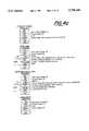
- Appendix Iis a description of operation (including flow-charts) of a Field Programmable Gate Array
- FIG. 1is a general block diagram of the wireless data communication network according to the present invention.
- FIG. 2is a pictorial representation of the channel frame format utilized in the multiple-access signalling protocol of the present invention
- FIG. 3is a timing cycle diagram illustrating the two-stage reservation-based polling protocol and data exchange system of the present invention
- FIGS. 4A-Cprovide a summary of network control function by frame type in accordance with the invention along with a description of frame content within individual fields of the frame;
- FIG. 5depicts a slot arrangement used within the request period in accordance with the invention
- FIG. 6is a timing cycle diagram similar to that of FIG. 3 illustrating slot usage.
- FIG. 7is a timing cycle diagram similar to that of FIG. 6, wherein acknowledgement signals are returned to the remote stations after each data message;
- FIG. 8is a perspective view showing the general block diagram of the wireless data communication network of FIG. 1 in the context of use;
- FIG. 9is a detailed block diagram of one of the remote stations of the data communication network shown in FIG. 1;
- FIG. 10is a perspective top view of a transceiver section of the remote station of FIG. 9;
- FIG. 11is a perspective bottom view of a transceiver section of the remote station of FIG. 9;
- FIG. 12is a perspective side view of a photodiode module of the remote station of FIG. 9;
- FIG. 13is a detailed block diagram of the central station of the data communication network of FIG. 1;
- FIG. 14is a perspective top and side view of the stationary transceiver of FIG. 13;
- FIG. 15is a block diagram of IR signal processing occurring within FIG. 9;
- FIG. 16is a prior art photodiode transimpedance amplifier
- FIG. 17is a floating photodiode amplifier of FIG. 15;
- FIG. 18is an alternate embodiment of the floating photodiode transimpedance amplifier of FIG. 17;
- FIG. 19is another alternate embodiment of the floating photodiode transimpedance amplifier of FIG. 17;
- FIG. 20is a third alternate embodiment of the floating photodiode transimpedance amplifier of FIG. 17.
- FIG. 21is a block diagram of IR signal processing occurring within FIG. 13.
- the solution to the problem of communication between a central station and a plurality of remote stations within an enclosed area, such as a hall or auditorium in a mobile context, without the problems associated with electromagnetic interferencelies, conceptually, in the use of diffuse infrared signals.
- Infrared transceivers disposed within a transceiver section of a remote station and within an at least one stationary transceiving devices distributed around the periphery of the enclosed area and interconnected with the central stationare used for the exchange of such signals.
- the remote stations and stationary transceiving devicesare constructed to sense and detect infra-red (IR) signals received not only directly (line-of-sight), but also signals that may be reflected from the wall (or walls) of the enclosed area or from objects within the enclosed area.
- IRinfra-red
- the systemcomprises a central station 12 and a number of remote stations 14.
- the central station 12may be a stand-alone data processing and control entity or may be an access point (AP) used in conjunction with other data processors and systems over a larger hard-wired network.
- APaccess point
- Central station 12communicates with remote stations 14 through optical infrared transceivers 16 coupled to the central station via a hard-wired link 18. While stationary transceiver 16 is shown in FIG. 1 as a single station, it is to be understood the transceiver 16 may actually (depending on a size of an enclosed volume of spaced in which the system 10 is used) be comprised of a number of transceivers distributed throughout a transmission space. For simplicity, infrared transceiver 16 will be described in terms of a single infrared transceiver station.
- Each of the remote stations 14includes an optical infrared transceiver which communicates with the central station by sending and receiving data messages over an infrared link 19.
- the central stationmay utilize the data messages itself, or route the data messages on to a different station in a local area network.
- each of the remote stationsis a portable, hand-held, battery-powered computer having an integrated infrared transceiver, as will be described in detail below.
- the remote stationsmay also include a keypad for data input, and a display for data output.
- the present inventionis particularly adapted for two-way communication over a single-frequency infrared channel transmitting data packets in the half-duplex mode of operation, the present invention can also be used in a full duplex mode over multi-frequency channels.
- infrared link 19has a 4 Megabit per second data rate using Return-To-Zero with Bit Insertion (RZBI) encoding scheme.
- RZBIReturn-To-Zero with Bit Insertion
- the present inventionis not limited for use with only wireless links or the particular type of channel or data communications scheme shown here.
- FIG. 2illustrates the specific channel frame format 20 used under the protocol for all information transfer and supervisory commands.
- the frame format of the inventionbasically follows the High-level Data Link Control (HDLC) data communication line protocol specification of the CCITT, or the Synchronous Data Link Control (SDLC) protocol specified by IBM.
- HDLCHigh-level Data Link Control
- SDLCSynchronous Data Link Control
- each frameis subdivided into a number of individual fields, wherein each field is comprised of a number of 8-bit bytes.
- channel frame format 20
- Preamble (PRE) 22This field is a 3-byte field whose purpose is to provide a means of establishing bit synchronization of the receiver with the received signal including the clock recovery signal.
- the value of the preambleis typically chosen to have a high content of transitions (e.g., "FFFFFF" because in RZBI encoding each "1" bit provides a high-low transition).
- Start Delimiter (SD) 24The purpose of the SD frame is to provide byte synchronization within the receiver.
- the 8 contiguous bits of the patternprovide a clear indication of the boundary between the "1" bits of the PRE and the bits of the SD. It is a unique "illegal" data structure because the bit insertion of the modulation scheme prevents this number of contiguous zero bits from occurring within the data (anyplace between the SD and ED fields).
- DID 26This field contains the 2-byte address of the station to which the frame is being sent. In other words, in a polling frame, the DID field of a frame transmitted to a remote station first identifies the particular remote station being polled by the central station and then the DID field of a return frame identifies the central station as the destination for the data message being returned by the remote station. Each of the stations is assigned a unique identification code, or address. The remote stations typically receive a new DID address each time the remote station registers with the network 10. However, a dynamic address determination procedure could also be used where the DID address changes during a data exchange under some need-based algorithm.
- the addresses of remote stationsbegin with 0000 hex and increase to a maximum amount determined by the number of remote stations allowed in the network (e.g., 7FFF hexadecimal).
- Controller stationse.g., central station 12
- may be assigned other numerical valuese.g., 8000-EEED hexadecimal.
- a value of FFFF hex in this fielddenotes a broadcast frame, which would be received by all stations.
- Source Identifier (SID) 28This field is the 2-byte address of the station sending the frame. To ensure the integrity of the data being transmitted, both the destination and source addresses are included within each frame.
- Type Field (TYP) 30The 1-byte field indicates to the receiver how to interpret a frame's content and in effect provides a control function.
- a summary of the possible types of framesare as follows: RSYNC, MRSYNC, RegRTS, RTS, FORF, DSYNC, EDSYNC, RegCTS, CTS, DATA, MDATA, and ACK.
- the meaning and content of the types of frames listedmay be best understood by reference to FIGS. 4A-C. The use of the frames may be best understood by reference to subsequent sections.
- Control Flags (CTL) 32This is a 1-byte control field containing bit-mapped flags, primarily used for supervising commands.
- control field 32includes priority flags and retransmission flags, which will be described below.
- INFO 34This is a variable length field used for transferring data.
- the INFO field 34is also used in conjunction with certain types of frames (e.g., RSYNC, MRSYNC, DYSNC, and EDSYNC) as a repository for an indicia of epoch location (e.g., the location of upward data transfer period (upward period), broadcast period, and downward data transfer period (downward period) within the overall data exchange period (data period)).
- FCSFrame Check Sequence
- CRCcyclic redundancy check
- End Delimiter (ED) 38 and Postamble (Post) 40The purpose of the ED 38 is to allow the receiver to detect an end of frame.
- the purpose of the POST 40is to prevent the receiver from mistaking an ED/POST combination for an SD/DID combination in that the hexadecimal value of 0EEEE would be an invalid DID.
- FIG. 3illustrates a repeating frame structure (superframe) used by the system 10 to exchange information between the central station 12 and the remote station 14.
- superframea repeating frame structure
- Superframesare not always of the same temporal length.
- the superframemay be divided into a variable length period used for receipt of access requests (request period) 50 and a variable length field used for data exchanges (data period) 51.
- the central station 12identifies the beginning of the superframe to the remote stations 14 by transmission of a request synchronization (RSYNC) frame or a mandatory request synchronization (MRSYNC) frame 52.
- RSYNCrequest synchronization
- MRSYNCmandatory request synchronization
- the remote stations 14identify the RSYNC or MRSYNC frames by reference to the type field of the frame (FIGS. 4A-C).
- the RSYNC or MRSYNC frame 52provides information within the INFO field 34 (FIG.
- the slot informationis used by the remote stations to facilitate system access (to be explained later) or to power-down during the request period 50 if the remote station 14 does not need access to the network 10.
- the network 10enters a data period 51.
- the central station 12identifies the beginning of the data period 51 to the remote station 14 by transmission of a data descriptor frame 53 (e.g., a data synchronization (DSYNC) or extended data synchronization (EDSYNC) frame).
- a data descriptor frame 53e.g., a data synchronization (DSYNC) or extended data synchronization (EDSYNC) frame.
- Contained within the INFO field 34 (FIG. 4A) of the DSYNC or EDSYNC frame 53is temporal information relative to the length of each subsection of the data period 51.
- the temporal informationis used by the remote stations 14 to reduce a duty cycle of activation by powering-down during appropriate portions of the data period 51.
- the slots of the request periodare divided into two groups where a first group of slots allows for random access under a contention based protocol (contention slots) and a second group of slots allows for access under a non-contention protocol (reserved slots) (e.g., under an implied polling protocol).
- the number of contention slotsmay be constant or may vary based upon an estimate of the number of unregistered remote stations within the service coverage area of the network 10.
- the number of reserved slotsis adjusted based upon loading.
- the remote station 14first monitors for a RSYNC or MRSYNC frame 52. Since the remote station 14 does not yet have a reserved slot, the remote station 14 must access the network 10 through a contention slot.
- the remote station 14identifies contention slots by examining the contents of the INFO field 34 of the RSYNC or MRSYNC frame 52. Contained inter alia within the INFO field 34 of the RSYNC or MRSYNC frame (FIG. 4A) is the total number of slots in the request period and the total number of reserved slots.
- the remote station 14can determine the location of the contention slots. Access may then be secured through a randomly selected contention slot.
- FIG. 5depicts a request period having 10 slots. If the reserved slots were designated as being slots 1-7, then slots 8-10 would be the contention slots.
- An INFO field 34 of an RSYNC or MRSYNC frame 52 in such a casewould indicate a total slot number of 10 and a total reserved slot number of 7.
- the remote stationwould then randomly generate a number in the range of 1 to 3 and add the randomly selected number to 7 for a final determination of the contention slot to be used in requesting access.
- the remote station 14In requesting access to the network 10, the remote station 14 sends a registration request to send (RegRTS) frame (FIG. 4B) within the selected contention slot.
- the INFO field 34 of the RegRTS framecontains a 48 bit address of the requesting remote station 14 along with coding within the type field that the frame is a RegRTS frame.
- the central station 12Upon receipt of the RegRTS from the remote station 14 by the central station 12, the central station 12 verifies by reference to a memory (not shown) that the address of the remote station 14 is one that is authorized to access the network 10 and that the remote station 14 has a software version compatible with the network 10. Upon verifying that the remote station 14 is an authorized user and is compatible with the network 10, the central station 12 issues a local identifier in favor of the remote station 14. The central station 12, on the other hand, does not immediately transmit the local identification to the remote station. Under the invention the central station waits until the next downward portion of the data period 51 before transmitting the identifier to the requesting remote station 14.
- the central station 12may create a reserved slot for the remote station 14 by expanding the length of the request period to 11 slots or may assign the remote station 14 to an unoccupied slot of reserved slots 1-7 (FIG. 5).
- the central station 12may de-allocate a slot previously reserved for use by other remote stations 14 based on certain operating parameters.
- the central station 12may deallocate slots for instance where the time since the last use of the slot exceeds some threshold value or if the remote station 14 does not respond to a known number of consecutive MRSYNC frames.
- the central station 12transmits the local identifier to the remote station 14 through use of a registration clear to send (RegCTS) frame (FIG. 4B).
- the remote stationretrieves the local identifier and, using the retrieved local identifier, may transmit a Request to Send (RTS) within the designated reserved slot under an implicit polling format during the request period 50 of the next superframe.
- RTSRequest to Send
- the remote station 14upon receipt of a RegCTS may immediately respond by transmitting data.
- a central station 12may transmit a RegCTS at any time to fill "holes" in the request period (e.g., when a remote station 14 is deactivated or leaves the service coverage area of the network 10).
- implicit pollingis performed during the request period 50, and explicit polling--of only those remote stations which requested access to the channel--is performed during the data period 51.
- the central stationbroadcasts an RSYNC or MRSYNC frame 52 to all the remote stations.
- the RSYNC or MRSYNC frameis issued periodically, and it defines the start of a number of time slots of the request period.
- the central stationsends an RSYNC or MRSYNC frame at least once every second. If there is less data to exchange then the superframe would occur more often, but not more often than once every 100 ms. If there were less data than could be transferred within the 100 ms interval, then the communication channel would be idle for a portion of the 100 ms.
- an RTS of the remote station 14specifies the number of data frames it wants to send during the superframe. It is then up to the central station 12 to determine how many times a remote station 14 gets polled. For instance, a central station 12 wouldn't let an entire superframe be "eaten up" by a single station if it requests to be polled too often. Once a request period 50 is complete, the central station 12 has a picture of all upward and downward data periods, and it will divide up the superframe equitably.
- a central station 12may indicate within the RTS frame during the RTS/CTS/DATA/ACK sequence how many frames it will send to the remote station 14 during a superframe.
- the use of a "more" bitindicates to the remote station 14 that there is more data to be transmitted during the superframe.
- Every remote stationhas a preassigned waiting period that will begin upon the reception of the RSYNC or MRSYNC frame. These waiting periods are illustrated as time slots TS in FIG. 6, which fill up the remainder of the request period 50.
- remote station 1Since remote station 1 has been assigned the first time slot, it issues a reserved slot request RR frame 54 if it has data to transmit on the channel. Hence, the first time slot has been replaced with the reserved slot request frame RR 1 (RTS frame) transmitted from remote station 1. As seen in the example of FIG. 6, no reserved slot request frame was issued in time slot 2 (frame 55), and a reserved slot request frame RR 3 was issued from remote station 3 in time slot 3 (frame 56).
- a maximum number X-X c(where X is total slots and X c is contention slots) denotes the number of active remote stations in the network, and, accordingly, the number of preassigned time slots.
- the central stationAfter every station has been given a chance to make a reservation, the central station will switch to a modified explicit polling mode, wherein it will sequentially issue a CTS frame to every remote station 14 that made a reservation.
- the central station 12Before the central station 12 begins the explicit polling, on the other hand, the central station 12 must describe the data period 50 for the benefit of those remote stations 14 that may wish to power-down for portions of the data period 50.
- the central station 12describes the data period 50 to the remote stations 14 by transmitting a DSYNC or EDSYNC frame 53.
- the DSYNC and EDSYNC framesdiffer primarily in the amount of information provided. In general, the EDSYNC allows for a lower duty cycle of remote stations 14.
- a remote station not needing to transfer data to the central station 12may use the time period specified to deactivate its transmitter and receiver until a point just before the broadcast period, where the remote station 14 must again re-activate its receiver for the receipt of system information during the broadcast period.
- the central stationpolls the first remote station during frame 60 of the upward period with CTS frame P 1 , since remote station 1 sent its reserved slot request frame RR 1 during frame 54. Immediately upon receiving the poll signal addressed to remote station 1, that station responds with its data packet DATA 1 during frame 62. The central station then checks its poll list to determine which remote station is to be polled next. In the example shown, remote station 3 is polled via poll frame P 3 during frame 64, and it responds with its data packet DATA 3 during frame 66. The polling ends upon the completion of the response of the last station on the list, which, in this case, was remote station 3.
- Priority message capabilityis also provided for in the reservation-based polling and data exchange protocol of the present invention.
- the control field 32 of the channel frame format 20includes a number of bit-mapped priority flags. In the preferred embodiment, four levels of priority can be implemented using two priority flag bits. If any remote station had a priority message to send, then that station would set its priority flags to the appropriate priority level, and transmit a reserved slot request RR frame to the central station in its preassigned time slot during the reserved slot request period. Upon receipt of this reserved slot request frame containing priority information, the central station would rearrange the poll list into priority-level order. Accordingly, the central station would poll the remote stations in priority-level order.
- the timing cycle diagram shown in FIG. 6can be used to illustrate the reservation-based polling protocol with priority-level polling. Assume that the time slots TS 1 , TS 2 , TS 3 , (frames 54-56) of the reserved slot request period are sequentially assigned to correspond with three remote stations 1-3. If all three remote stations had non-priority messages to send, then each would send its reserved slot request RR frame during the appropriate time slot, and the central station would poll each remote station in numerical order, i.e., the poll list would appear as: P 1 , P 2 , P 3 .
- remote station 3had a level-one priority message to send
- remote station 2had a level-two priority message to send
- these stationswould indicate such using the priority flags in the control fields of their reserved slot request frames.
- the central stationwould then reorder its poll list to appear as: P 3 , P 2 , P 1 .
- the remote stationsare polled in priority-level order. Numerous other multiple-level priority message schemes can be used with the present invention, a few of which will be described below.
- FIG. 7represents a similar timing cycle diagram to that of FIG. 6, with the addition that an acknowledgement (ACK) frame is transmitted from the central station to the remote station after the reception of each data message from the remote station.
- ACKacknowledgement
- the central station 12In order to send an ACK frame, the central station 12 must, first, correctly receive the data message.
- FIG. 7illustrates that, during the reservation request period, remote stations 1 and 3 have transmitted reserved slot request frames 54 and 56, respectively. Therefore, during the upward data transfer period, each of these two remote stations is polled. As before, a first poll frame P 1 is issued from the central station in frame 60, and data packet DATA 1 from remote station 1 is returned during frame 62. However, now an acknowledgement frame AK 1 is sent from the central station to remote station 1 during frame 63. A similar polling/data transfer/acknowledgement sequence occurs for remote station 3 during frames 64, 66, and 67. As only partially shown in FIG. 7, remote station X-X c was polled, it transmitted its data packet, and its acknowledgment frame AK x is shown being returned during frame 69.
- the remote station 14If the remote station 14 does not receive an acknowledgement (ACK) from the central station 12 following a data transfer (or does not get polled), then the remote station 14 sends a reserved slot request (RR) during the next request period 50. If the remote station 14 does not get a response after 3 tries, the remote station may try again later or discard the data.
- ACKacknowledgement
- RRreserved slot request
- the broadcast periodfollows the upward period. Any stations which may have de-activated during the upward period must re-activate for the broadcast period.
- datais broadcast from the central station 12 to all remote stations 14.
- Data frames (FIG. 4C) during the broadcast periodare sent with the broadcast DID (i.e., FFFF hexadecimal). Broadcast data frames are not preceded by an RTS/CTS exchange and are not acknowledged by receiving remote stations 14. If there is no broadcast data to be sent from the central station 12 to the remote stations 14, then an EDSYNC frame 53 at the beginning of the data period 51 may be used to indicate a broadcast length of zero.
- the downward data periodFollowing the broadcast period is the downward data period. If the data descriptor 53 at the beginning of the data period 51 were a DSYNC frame, then all remote stations 14 must remain activated during the downward data period.
- the data descriptor 53were an EDSYNC frame
- the contents of the EDSYNCwould provide advance notification of which remote station(s) 14 would receive data and, therefore, which remote stations 14 would remain activated during the downward data period.
- Other remote stations 14 not present within the list of the EDSYNC framemay deactivate for the duration of the downward data period.
- Data transfer from the central station 12 to the remote stations 14 during the downward periodmay occur under either of two possible scenarios.
- the central stationmay either transmit an RTS and wait for a CTS before transmitting the data, or may simply transmit a data frame and wait for an acknowledgement response.
- the use of the RTS by the central station 12avoids the unnecessary transmission of data when the remote station 14 may not be within range of the central station 12.
- the use of the RTS/CTS exchangecauses more overall data traffic between the central station 12 and remote station 14.
- a negative acknowledgment framewould be returned to the central station. If the central station received neither an acknowledgement frame nor a negative acknowledgement frame from the remote station, then the central station would retransmit the same data message in the next superframe.
- the central station 12begins its retransmission with the retry bit of the RTS frame set.
- the central stationbegins its retransmission with the retry bit of the DATA frame set.
- the central stationmay be advantageous for the central station to track and report on the number of active remote stations in the network--whether or not each remote station has a data message to send.
- the central controllerwould issue a mandatory request synchronization (MRSYNC) frame to all of the remote stations.
- MRSYNCmandatory request synchronization
- a remote stationreceives this frame, it responds with an RTS frame if it has data to send, or it responds with a forfeit (FORF) frame if it does not.
- FRFforfeit
- the central stationassumes that the particular remote station 14 is not presently active. In this manner, all of the active remote stations will be accounted for by the system without affecting the throughput of the data communication channel.
- the central stationPeriodically, issues a frame (RSYNC, MRSYNC, DSYNC, or EDSYNC) including a superframe number.
- the superframe numbermay be used by the remote stations 14 as a functional check of proper operation (e.g., that a particular sleep mode interval did not cause a remote station 14 to miss part of a superframe).
- FIG. 8Shown in FIG. 8 is a perspective view of a wireless multipoint data communication system 10, in a context of use within an enclosed area 11 such as a hall or auditorium.
- communicated signals 19 between a remote station 14may be transceived along a direct path 13 or an indirect path 15 where a transmitted signal is reflected from a wall or walls of the enclosed area before being received by the remote station 14 or stationary tranceiver (e.g., stationary transceiver 16a).
- stationary tranceivere.g., stationary transceiver 16a
- each remote station 14includes a transceiver section 104 which communicates with the central station 12 via an optical-infrared data link 19 and with a data processing section 102 via an RS232 interconnect 103.
- the heart of the transceiver section 104 of the remote station 14is a communication processor 114 operating at 32 Mhz.
- Remote controller 110interfaces with a data processor 112 and the communication processor 114, such that data processor 112 can communicate over the infrared link using the polling protocol described above.
- data processing section 102may be part of an EPSON Model No. H1001BEW hand-held (palmtop) computer.
- Communication processor 114 of the transceiver section 104may be a Field Programmable Gate Array (FPGA) with custom programmed logic provided by Spectrix Corp., of Evanston Ill. (see Appendix I).
- Communication processor 114controls an infrared transmitter 116 and an infrared receiver 118.
- a infrared filter cover 101that surrounds and protects the transceiver section 104 of the remote station 14.
- the cover 101functions to increase the sensitivity of the IR receivers 118 by blocking undesired wavelengths (e.g., visible light to U.V.) from a received signal.
- the coveris constructed of a polycarbonate (e.g., LexanTM such as that sold by General Electric under part number 141) with a light absorbing material (e.g., a dye such as that sold by General Electric under part number 701055) disposed throughout the material of the cover 101.
- FIG. 10A top perspective view of the transceiver section 104 is shown in FIG. 10 with the protective cover 101 removed. Shown in the top perspective view (FIG. 10) of the transceiver section 104 is a phantom view of the communication processor 114 in communication with the IR transmitter 116.
- the IR transmitter 116is comprised of IR drivers 107 and IR light emitting diodes (LEDs) 105.
- FIG. 10shows a set of 12 IR transmitters 105 arranged in a semi-circle along the top edge of the transceiver section 104, in 15 degree increments.
- the 12 IR transmittersmay be any commercially available light emitting diode (LED) having a high power output and a broad frequency response (e.g., a model number DN304 available from Stanley).
- the 12 IR transmitters 105provide a means of transmitting communicated information directly (line-of-sight) to stationary transceiving devices 16a, 16b or indirectly via reflections from the walls of enclosure 11. Under an embodiment of the invention, the IR transmitters 105 transmit information simultaneously to provide a diffuse transmission of communicated information from remote station 14 to stationary transceiver devices 16a, 16b.
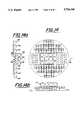
- FIG. 11is a bottom view of the transceiver module 104 of remote station 14.
- a set of 3 IR photodiode receiving modules 109(shown in greater detail in FIG. 12).
- Each module 109 of the transceiver module 104is disposed in a 53 degree relation to adjacent modules 109 of the transceiver module 104. Arranging the modules 109 in 53 degree relation enhances the ability of the transceiver module 104 to receive and detect diffuse IR radiation anywhere within a 180 degree field of view (90 degrees either side of a longitudinal axis of the remote station 14).
- each photodiode 111 of each receiving module 109is tilted on the module 109 by some enhanced receiving angle "a" (e.g., 11 degrees).
- the 6 IR receivers 111may be any commercially available photodiode having a large photo-active area and a broad frequency range (e.g., a model number VTP1150 from EGG Vactec).
- the electromagnetic shield 113is a commercially available expanded metal copper structure having holes substantially 2.00 mm in diameter.
- FIG. 13is a detailed block diagram of central station 12 of the data communication network shown in FIG. 1.
- the central stationincludes a number of external transceivers 16 (for simplicity, only one is shown in FIG. 13).
- infrared transceiver 16is located at a distance from central station 12, since a personal computer is used for the network controller and since the infrared link is limited to the confines of the enclosed area 11.
- a network controller 130interfaces an input/output port 132 to a communication processor 134 such that the reservation-based polling protocol of the present invention is used to transmit and receive data from infrared link 19 to I/O port 132 via infrared transmitter 136, infrared receiver 138, and hard-wired link 18.
- the function of network controller 130is performed by an IBM-compatible personal computer using a DOS-based operating system.
- the personal computertypically includes a memory 140, a clock 142, a display 144, and a keyboard 146.
- the communication processor 134(FIG. 13) is equipped with a signal measuring device 137.
- the network controller 130measures an infrared signal strength (either diffuse or line-of-sight) of each transmitting remote station 14 at each stationary transceiver 16 and selects the stationary transceiver providing the strongest signal measurement.
- the network controller 130may select a stationary transceiver 16a, 16b based upon a bit error rate (BER). If a BER is used, the network controller may measure the BER by comparing known sequences (e.g., DID) received from a remote station 14 by each stationary transceiver 16 and selecting the stationary transceiver 16 providing the fewest errors.
- DIDbit error rate
- Stationary transceivers 16are each attached to a wall of the enclosed area 11 and protected by a hemispherically shaped cover 139.
- the cover 139not only protects the stationary transceiver 16 from damage and contamination, but also serves as a radiation filter by blocking radiation outside the infrared spectrum (e.g., visible light to U.V.).
- the cover 139is fabricated of an acrylic (e.g., PlexiglasTM supplied by Autobass of Bristol, Pa. under catalog number 2711--UV Visible Blockout).
- FIG. 14is a perspective view of a stationary transceiver 16 as it would appear mounted to a wall of the enclosed area 11 with the cover 139 removed.
- the photodetectors 135 of the stationary transceiver 16are tilted 45 degrees to either side of a vertical plane 131 orthogonal to the wall of the enclosed area 11.
- Four other photodetectors 135are oriented parallel with the plane 131.
- the photodetectors 135may be any commercially available photodiode having a large photo-active area and a broad frequency response (e.g., a model number VTP1150 available from EGG Vactec).
- the photodiodes 135are provided with an electromagnetic shield 141 comprised of expanded metal.
- the transmitting LEDs 133 of FIG. 14occupy a similar relationship with respect to the vertical plane 131.
- the LEDs 133may be any of a number of commercially available LEDs having a high power output and a broad frequency response (e.g., a model number DN304 available from Stanley).
- Photodiodes 135 and LEDs 133each have an active receiving/transmitting arc of approximately 90 and 40 degrees, respectively.
- FIG. 15Shown in FIG. 15 is a signal processing block diagram for the infrared detector 118 of the remote stations 14.
- FIG. 21shows a corresponding signal processing block diagram for the receiver 138 of the stationary transceiver 16.
- the processing steps used within the receiver 118 and the receiver 138are functionally equivalent. Explanation of the processing steps will be offered in terms of the receiver 118 with differences related to receiver 138 noted in passing.
- photodiodeis used in FIG. 15, or "photodiode array" of FIG. 21, it is understood that the term may refer to a number of photodiodes connected in parallel.
- reference number 109is used to refer to a pair of photodiodes connected in parallel.
- FIG. 14the four photodiodes arranged in parallel relationship to the vertical axis 131 may be connected in parallel.
- the block diagram(FIG. 15) shows signal processing within blocks 202 and 204 for one of 3 photodiodes. Signal processing of the other two photodiodes (inputs 2 and 3 of block 206) are assumed to be the same. Likewise, signal processing within corresponding blocks 254, 256 of FIG. 21 for photodiode array #1 of the stationary transceiver 16 is the same for each of 3 photodiode arrays.
- the receiver 138 of the stationary transceiver 16simply adds the inputs of the 3 photodiodes in summer 258. Also, the function of averaging and filtering blocks 206 and 208 of FIG. 15 are shown combined in the summer block 258 of FIG. 21.
- the receiver 138also includes a differential line driver 268 which transfers the amplified limited signal through wireline 18 to the communication processor 134 for bandpass filtering and analog to digital conversion.
- an infrared signal 19 received by the photodiode 109is converted from a current signal to a voltage signal within a transimpedance amplifier 202.
- the voltage signalis bandpass filtered within the filter 204 having 3 dB points at 150 kHz and 5 MHz. Signals from the three photodiodes 1-3 are averaged within an averager 206 by summing and dividing by 3. Low frequency noise is removed by high pass filtering in a high pass filter 208.
- the signalis impedance buffered within a buffer 210 and amplitude limited within limiter 212.
- the signalis amplified by 20 dB in amplifier 214 and limited again in limiter 216.
- the signalis then amplified by 20 dB in another amplifier 218 and bandpass filtered in a filter 220 having a center frequency at 4 MHz and a bandwidth of 300-500 kHz.
- the signalis converted to the serially transmitted, digital format described above within an analog to digital (A/D) converter 222.
- FIG. 16shows a photodetector PD providing an input to transimpedance amplifier A through coupling capacitor C 1 .
- the photodiode PDreceives a supply signal V bb through supply resistor R b .
- Equivalent capacitor C PD(shown in phantom) represents the capacitance of the photodiode PD.
- the transimpedance amplifier Ais a high gain, inverting amplifier.
- the transimpedance amplifier Ahas a feedback resistor R x .
- the input impedance Z in of transimpedance amplifier A and feedback resistor R xto a first approximation, equals R/(1+voltage gain of A).
- the positive voltage source V bbapplies a voltage across the photodiode PD through supply resistor R b which reverse biases the photodiode junction, causing the photodiode PD to operate in the photoconductive mode.
- Currentpasses from the source V bb to ground through a circuit that includes the supply resistor R b and photodiode PD.
- the photodiode PDWhen the photodiode PD is subjected to a modulated light source of the correct wavelength, the photodiode PD modulates the current passing through the circuit from the source V bb to ground.
- the modulated current through the photodiodecauses a modulated current to be coupled through C 1 into the transimpedance amplifier A.
- the capacitor C 1acts to couple the modulated current to the input of A while blocking slow and/or large variations in voltage caused by photocurrent changes resulting from changes in ambient (non-signalling) light levels. At signalling frequencies, the reactance of C 1 is small compared to the effective input impedance Z in of the transimpedance amplifier A 1 .
- the supply resistor R bSince the supply resistor R b is relatively large compared to the imput impedance Z in of the transimpedance amplifier A, the supply resistor R b represents a minor, parasitic shunt path for signal current. Most of the signal current is sunk by the virtual ground formed at the input of A, represented by the input impedance Z in .
- the output of the transimpedance amplifier Ais a modulated voltage which is an analog of the optical stimulus of the photodiode PD.
- the amplitude of the output voltageis ideally R x times the current of the photodiode PD.
- the dominant limitation on the bandwidth of the prior art circuit shown in FIG. 16lies in the resistor-capacitor (RC) time constant inherent in the combination of C PD (the parasitic photodiode depletion layer capacitance) and the effective input impedance Z in of the transimpedance amplifier A.
- RCresistor-capacitor
- the prior art circuit of FIG. 16is also subject to other limitations which make the circuit of FIG. 16 not appropriate for the system 10 of the present invention. If the circuit of FIG. 16 is subjected to a strong optical source, the photodiode PD can pass a comparatively high current, resulting in the coupling capacitor C 1 rapidly attaining an abnormal charge condition (in the sense that it exceeds normal operating parameters for this circuit). The photodiode PD sinks current from the left side of C 1 while the resistor R x , connected to the output of the transimpedance amplifier A, sources current to the right side of C 1 . When the strong stimulus is removed, the only viable discharge path for restoring normal operating voltages to C 1 is through the supply resistor R b . Since the supply resistor R b is relatively large, the long time constant associated with C 1 and R b results in the circuit of FIG. 16 having a very slow recovery time, unacceptable for a high throughput system.
- a floating photodiode amplifier system(FIG. 17) is used as a diffuse infrared signal detector.
- Amplfier A 1is a non-inverting amplifier having a gain of slightly less than unity and a bandwidth of at least 12 MHz.
- the anode of the photodiode PD of the receiver 118, 138is returned to the output of transimpedance amplifier A 1 .
- the photodiode PDis reverse biased as in the previous example except that now its anode side is returned, not to a real ground, but to an artificial ground represented by the the low impedance output of the amplifier A 1 .
- the gain of A 1is chosen to have a value very near, but not exceeding, unity.
- the input impedance of the amplifier A 1 of FIG. 17is chosen to be very high (e.g., >200 k ⁇ ). Because of the high input impedance, a modulated photocurrent passing through the photodiode must also pass predominently through R b generating, in turn, a modulated signal voltage across R b . Since the voltage source V bb is fixed relative to ground and since one side of the supply resistor R b is fixed at the supply source V bb , it is clear that the modulated signal voltage may be detected at the cathode of the photodiode PD with respect to ground. Capacitor C 1 couples the signal voltage to the input of A 1 . An essentially identical copy of the signal appears at the output of the amplifier A 1 .
- the substantially passive transimpedance gain mechanism of the circuit of FIG. 17is practical for large photodiode/low speed systems, or for small photodiode/moderate speed systems, a high bandwidth photodetector amplifying circuit, with adequate transimpedance gain, may prove difficult to construct with the circuit of FIG. 17. Such a circuit may be difficult because the bandwidth of the circuit is limited by the time constant formed by the product of R b and the parasitic capacitance at the input of A 1 to ground. It may be noted, however, that the circuit of FIG. 17 is largely immune, by virtue of A 1 's high input impedance, to the slow recovery problem plaguing the circuit of FIG. 16.
- a second amplifier A 2 and feedback resistor R xare added to the previous circuit.
- amplifier A 1is a non-inverting amplifier having a gain of slightly less than unity and a bandwidth of at least 12 MHz.
- the input impedance of A1should be at least 200 k ⁇ and the output impedance less than 200 ⁇ .
- Amplifier A 2is an inverting amplifier having a gain of at least 30-40 volts per volt and a bandwidth of at least 12 MHz.
- the input impedance of A 2should be at least 10-20 higher times than the output impedance of A 1 .
- FIG. 19is an IR diffuse signal detector in accordance with another embodiment of the invention.
- the supply resistor R bhas been divided into two smaller resistors R 1 and R 2 .
- the embodimentseeks to improve the recovery time of the detector of FIG. 18 by dividing R b into two smaller resistors R 1 and R 2 where R 2 is a small fraction of R 1 .
- Capacitor C 1under the embodiment, couples signal voltage from the low impedance output of unity gain amplifier A 1 to the junction of R 1 and R 2 . Because C 1 and C 2 are shorts at the signalling frequency (4 MHz) of the system 10, the signalling voltage at the cathode of the photodiode PD is substantially equal to the signalling voltage at the input of the amplifier A 1 .
- a 1is substantially a unity gain amplifier, the output of A 1 is substantially equal to the input. Because the reactance of C 1 is much less than R 1 at the signalling frequency, the charge required to change the voltage across C 2 is supplied by C 1 through R 2 . Since R 2 is relatively small, the time required for the circuit of FIG. 19 to react to changes in ambient light levels is very fast.
- circuit of FIG. 19presents a means of signal detection that, at first blush, may appear to be an improvement, the performance of the circuit of FIG. 19 is still less than that desired. While C 1 does serve to supply charging current to C 2 , a new RC circuit has been created through the interaction of R 1 and C 1 .
- the circuit of FIG. 19is re-arranged somewhat in FIG. 20 to provide an embodiment of an IR diffuse detection circuit 202 not subject to time delays caused by coupling capacitors.
- the alterationis a subtle but critical change.
- the supply resistor R bis still present but (as with FIG. 19) split into two smaller resistors R 1 and R 2 .
- the embodimentuses the photodiode PD to isolate R 1 C 1 from R 2 C 2 .
- the resultis to produce two almost independent RC time constants, each of which is quite short and, through proper component selection, may be made substantially equal. Because the two RC networks do not overlay one another (as in the previous approach), definite, independent bounds can be placed on the time constants.
- the infrared detection circuits of FIG. 17, 18, and 20represent a significant advance of the circuit of FIG. 16. Where the circuits of FIGS. 17, 18, and 20 are combined with the other elements of FIG. 15, the result is a diffuse infrared communication system receiver that is capable of detecting high-speed infrared signals at substantially above 4 MHz, either line of sight or as reflections from the walls of an enclosure 11.
- the present inventionprovides a diffuse infrared local area communication system for a data communication network which efficiently utilizes a single channel even when only a fraction of the users have data messages to send at a given time.
- the diffuse infrared local area communication systemis particularly adapted for use with a large number of portable battery-powered computer devices communicating with a central station via an infrared link.
Landscapes
- Engineering & Computer Science (AREA)
- Physics & Mathematics (AREA)
- Electromagnetism (AREA)
- Computer Networks & Wireless Communication (AREA)
- Signal Processing (AREA)
- Power Engineering (AREA)
- Computing Systems (AREA)
- Mobile Radio Communication Systems (AREA)
- Small-Scale Networks (AREA)
Abstract
Description
Claims (5)
Priority Applications (4)
| Application Number | Priority Date | Filing Date | Title |
|---|---|---|---|
| US08/322,016US5724168A (en) | 1994-10-11 | 1994-10-11 | Wireless diffuse infrared LAN system |
| CA002203411ACA2203411A1 (en) | 1994-10-11 | 1995-10-03 | Wireless diffuse infrared lan system |
| PCT/US1995/012663WO1996011536A1 (en) | 1994-10-11 | 1995-10-03 | Wireless diffuse infrared lan system |
| EP95939482AEP0791252A4 (en) | 1994-10-11 | 1995-10-03 | Wireless diffuse infrared lan system |
Applications Claiming Priority (1)
| Application Number | Priority Date | Filing Date | Title |
|---|---|---|---|
| US08/322,016US5724168A (en) | 1994-10-11 | 1994-10-11 | Wireless diffuse infrared LAN system |
Publications (1)
| Publication Number | Publication Date |
|---|---|
| US5724168Atrue US5724168A (en) | 1998-03-03 |
Family
ID=23253040
Family Applications (1)
| Application Number | Title | Priority Date | Filing Date |
|---|---|---|---|
| US08/322,016Expired - LifetimeUS5724168A (en) | 1994-10-11 | 1994-10-11 | Wireless diffuse infrared LAN system |
Country Status (4)
| Country | Link |
|---|---|
| US (1) | US5724168A (en) |
| EP (1) | EP0791252A4 (en) |
| CA (1) | CA2203411A1 (en) |
| WO (1) | WO1996011536A1 (en) |
Cited By (196)
| Publication number | Priority date | Publication date | Assignee | Title |
|---|---|---|---|---|
| US5864708A (en)* | 1996-05-20 | 1999-01-26 | Croft; Daniel I. | Docking station for docking a portable computer with a wireless interface |
| US5903373A (en)* | 1996-07-03 | 1999-05-11 | Spectrix Corporation | Method and apparatus for locating a transmitter of a diffuse infrared signal within an enclosed area |
| US5917634A (en)* | 1995-03-27 | 1999-06-29 | Sony Corporation | Optical-signal transmitting apparatus, optical-signal receiving apparatus, and optical-signal transmitting and receiving system |
| US5986787A (en)* | 1996-03-15 | 1999-11-16 | Kabushiki Kaisha Toshiba | Near-infrared communication apparatus |
| US6008923A (en)* | 1998-03-16 | 1999-12-28 | Netschools Corporation | Multiple beam communication network with beam selectivity |
| US6256129B1 (en)* | 1997-03-28 | 2001-07-03 | Samsung Electronics Co., Ltd. | Portable computer and method of automatically controlling direction of infrared signal transmission and reception |
| US6256296B1 (en) | 1997-12-17 | 2001-07-03 | Yaron Ruziak | Network communications link |
| US6377376B1 (en)* | 1998-03-26 | 2002-04-23 | International Business Machines Corporation | Optoelectronic transceiver having emission angle equal to reception angle |
| US6456410B1 (en)* | 1994-12-21 | 2002-09-24 | Lucent Technologies Inc. | Optical data communication system and method |
| US20020143970A1 (en)* | 2000-09-18 | 2002-10-03 | Sharp Labs | Devices, methods and software for centralized session planning while in a DCF mode |
| WO2002067465A3 (en)* | 2001-02-16 | 2002-10-17 | Penn State Res Found | Wireless infrared multi-spot diffusing communication system |
| US6469634B1 (en)* | 1996-06-03 | 2002-10-22 | Intel Corporation | Method and apparatus for controlling the operation of electronic entertainment devices in an entertainment system |
| US20040009768A1 (en)* | 2002-04-30 | 2004-01-15 | Waters John Deryk | Wireless data network security |
| US20040198221A1 (en)* | 2002-03-06 | 2004-10-07 | Samsung Electronics Co., Ltd. | Wireless communication module capable of waking up a wireless communication device in park mode based on connectionless broadcast and method thereof |
| US20040249999A1 (en)* | 2003-04-04 | 2004-12-09 | Connolly Brian Edmond | Method and system for transferring analyte test data |
| WO2005048492A1 (en)* | 2003-11-14 | 2005-05-26 | Koninklijke Philips Electronics N.V. | Space-time coded diffuse-ir networking with photon density waves |
| US6907013B1 (en) | 1997-12-17 | 2005-06-14 | Infracom, Ltd. | Network communications link |
| US20050231134A1 (en)* | 2004-04-15 | 2005-10-20 | Alberto Sid | Remote controlled intelligent lighting system |
| US7333181B1 (en)* | 2005-05-13 | 2008-02-19 | Oceanit Laboratories, Inc. | Methods for the use and manufacture of infrared position sensing detector focal plane arrays for optical tracking |
| US20090269073A1 (en)* | 2005-08-31 | 2009-10-29 | Kyocera Corporation | Transmitter apparatus and communication system |
| US20100054748A1 (en)* | 2007-03-13 | 2010-03-04 | Yoshiyuki Sato | Receiver and system for visible light communication |
| US20100161840A1 (en)* | 2008-12-20 | 2010-06-24 | Mccollum Peter Lloyd | Data Reporting Systems and Methods |
| US20120069786A1 (en)* | 2010-09-22 | 2012-03-22 | Motorola, Inc. | Channel structure for non-contention based windows and contention based random access requests |
| US20140067144A1 (en)* | 2012-08-31 | 2014-03-06 | Hon Hai Precision Industry Co., Ltd. | Smart switch and smart home system using the same |
| US20140064737A1 (en)* | 2012-08-31 | 2014-03-06 | Hon Hai Precision Industry Co., Ltd. | Smart switch and remote control system using the same |
| US20140088779A1 (en)* | 2012-09-25 | 2014-03-27 | Hon Hai Precision Industry Co., Ltd. | Smart power strip and smart home system using the same |
| US20140103214A1 (en)* | 2011-04-21 | 2014-04-17 | Antoine Yvon Messiou | Passive infra red detector |
| US9119127B1 (en) | 2012-12-05 | 2015-08-25 | At&T Intellectual Property I, Lp | Backhaul link for distributed antenna system |
| US9154966B2 (en) | 2013-11-06 | 2015-10-06 | At&T Intellectual Property I, Lp | Surface-wave communications and methods thereof |
| US9209902B2 (en) | 2013-12-10 | 2015-12-08 | At&T Intellectual Property I, L.P. | Quasi-optical coupler |
| US9312919B1 (en) | 2014-10-21 | 2016-04-12 | At&T Intellectual Property I, Lp | Transmission device with impairment compensation and methods for use therewith |
| US9461706B1 (en) | 2015-07-31 | 2016-10-04 | At&T Intellectual Property I, Lp | Method and apparatus for exchanging communication signals |
| US9490869B1 (en) | 2015-05-14 | 2016-11-08 | At&T Intellectual Property I, L.P. | Transmission medium having multiple cores and methods for use therewith |
| US9503189B2 (en) | 2014-10-10 | 2016-11-22 | At&T Intellectual Property I, L.P. | Method and apparatus for arranging communication sessions in a communication system |
| US9509415B1 (en) | 2015-06-25 | 2016-11-29 | At&T Intellectual Property I, L.P. | Methods and apparatus for inducing a fundamental wave mode on a transmission medium |
| US9520945B2 (en) | 2014-10-21 | 2016-12-13 | At&T Intellectual Property I, L.P. | Apparatus for providing communication services and methods thereof |
| US9525524B2 (en) | 2013-05-31 | 2016-12-20 | At&T Intellectual Property I, L.P. | Remote distributed antenna system |
| US9525210B2 (en) | 2014-10-21 | 2016-12-20 | At&T Intellectual Property I, L.P. | Guided-wave transmission device with non-fundamental mode propagation and methods for use therewith |
| US9531427B2 (en) | 2014-11-20 | 2016-12-27 | At&T Intellectual Property I, L.P. | Transmission device with mode division multiplexing and methods for use therewith |
| US9564947B2 (en) | 2014-10-21 | 2017-02-07 | At&T Intellectual Property I, L.P. | Guided-wave transmission device with diversity and methods for use therewith |
| US9577306B2 (en) | 2014-10-21 | 2017-02-21 | At&T Intellectual Property I, L.P. | Guided-wave transmission device and methods for use therewith |
| US9608692B2 (en) | 2015-06-11 | 2017-03-28 | At&T Intellectual Property I, L.P. | Repeater and methods for use therewith |
| US9608740B2 (en) | 2015-07-15 | 2017-03-28 | At&T Intellectual Property I, L.P. | Method and apparatus for launching a wave mode that mitigates interference |
| US9615269B2 (en) | 2014-10-02 | 2017-04-04 | At&T Intellectual Property I, L.P. | Method and apparatus that provides fault tolerance in a communication network |
| US9628854B2 (en) | 2014-09-29 | 2017-04-18 | At&T Intellectual Property I, L.P. | Method and apparatus for distributing content in a communication network |
| US9628116B2 (en) | 2015-07-14 | 2017-04-18 | At&T Intellectual Property I, L.P. | Apparatus and methods for transmitting wireless signals |
| US9640850B2 (en) | 2015-06-25 | 2017-05-02 | At&T Intellectual Property I, L.P. | Methods and apparatus for inducing a non-fundamental wave mode on a transmission medium |
| US9654173B2 (en) | 2014-11-20 | 2017-05-16 | At&T Intellectual Property I, L.P. | Apparatus for powering a communication device and methods thereof |
| US9653770B2 (en) | 2014-10-21 | 2017-05-16 | At&T Intellectual Property I, L.P. | Guided wave coupler, coupling module and methods for use therewith |
| US9667317B2 (en) | 2015-06-15 | 2017-05-30 | At&T Intellectual Property I, L.P. | Method and apparatus for providing security using network traffic adjustments |
| US9680670B2 (en) | 2014-11-20 | 2017-06-13 | At&T Intellectual Property I, L.P. | Transmission device with channel equalization and control and methods for use therewith |
| US9685992B2 (en) | 2014-10-03 | 2017-06-20 | At&T Intellectual Property I, L.P. | Circuit panel network and methods thereof |
| US9692101B2 (en) | 2014-08-26 | 2017-06-27 | At&T Intellectual Property I, L.P. | Guided wave couplers for coupling electromagnetic waves between a waveguide surface and a surface of a wire |
| US9705571B2 (en) | 2015-09-16 | 2017-07-11 | At&T Intellectual Property I, L.P. | Method and apparatus for use with a radio distributed antenna system |
| US9705561B2 (en) | 2015-04-24 | 2017-07-11 | At&T Intellectual Property I, L.P. | Directional coupling device and methods for use therewith |
| US9722318B2 (en) | 2015-07-14 | 2017-08-01 | At&T Intellectual Property I, L.P. | Method and apparatus for coupling an antenna to a device |
| US9729197B2 (en) | 2015-10-01 | 2017-08-08 | At&T Intellectual Property I, L.P. | Method and apparatus for communicating network management traffic over a network |
| US9735833B2 (en) | 2015-07-31 | 2017-08-15 | At&T Intellectual Property I, L.P. | Method and apparatus for communications management in a neighborhood network |
| US9742462B2 (en) | 2014-12-04 | 2017-08-22 | At&T Intellectual Property I, L.P. | Transmission medium and communication interfaces and methods for use therewith |
| US9749013B2 (en) | 2015-03-17 | 2017-08-29 | At&T Intellectual Property I, L.P. | Method and apparatus for reducing attenuation of electromagnetic waves guided by a transmission medium |
| US9748626B2 (en) | 2015-05-14 | 2017-08-29 | At&T Intellectual Property I, L.P. | Plurality of cables having different cross-sectional shapes which are bundled together to form a transmission medium |
| US9749053B2 (en) | 2015-07-23 | 2017-08-29 | At&T Intellectual Property I, L.P. | Node device, repeater and methods for use therewith |
| US9755697B2 (en) | 2014-09-15 | 2017-09-05 | At&T Intellectual Property I, L.P. | Method and apparatus for sensing a condition in a transmission medium of electromagnetic waves |
| US9762289B2 (en) | 2014-10-14 | 2017-09-12 | At&T Intellectual Property I, L.P. | Method and apparatus for transmitting or receiving signals in a transportation system |
| US9769020B2 (en) | 2014-10-21 | 2017-09-19 | At&T Intellectual Property I, L.P. | Method and apparatus for responding to events affecting communications in a communication network |
| US9769128B2 (en) | 2015-09-28 | 2017-09-19 | At&T Intellectual Property I, L.P. | Method and apparatus for encryption of communications over a network |
| US9780834B2 (en) | 2014-10-21 | 2017-10-03 | At&T Intellectual Property I, L.P. | Method and apparatus for transmitting electromagnetic waves |
| US9793954B2 (en) | 2015-04-28 | 2017-10-17 | At&T Intellectual Property I, L.P. | Magnetic coupling device and methods for use therewith |
| US9793951B2 (en) | 2015-07-15 | 2017-10-17 | At&T Intellectual Property I, L.P. | Method and apparatus for launching a wave mode that mitigates interference |
| US9793955B2 (en) | 2015-04-24 | 2017-10-17 | At&T Intellectual Property I, Lp | Passive electrical coupling device and methods for use therewith |
| US9800327B2 (en) | 2014-11-20 | 2017-10-24 | At&T Intellectual Property I, L.P. | Apparatus for controlling operations of a communication device and methods thereof |
| US9820146B2 (en) | 2015-06-12 | 2017-11-14 | At&T Intellectual Property I, L.P. | Method and apparatus for authentication and identity management of communicating devices |
| US9838896B1 (en) | 2016-12-09 | 2017-12-05 | At&T Intellectual Property I, L.P. | Method and apparatus for assessing network coverage |
| US9836957B2 (en) | 2015-07-14 | 2017-12-05 | At&T Intellectual Property I, L.P. | Method and apparatus for communicating with premises equipment |
| US9847566B2 (en) | 2015-07-14 | 2017-12-19 | At&T Intellectual Property I, L.P. | Method and apparatus for adjusting a field of a signal to mitigate interference |
| US9847850B2 (en) | 2014-10-14 | 2017-12-19 | At&T Intellectual Property I, L.P. | Method and apparatus for adjusting a mode of communication in a communication network |
| US9853342B2 (en) | 2015-07-14 | 2017-12-26 | At&T Intellectual Property I, L.P. | Dielectric transmission medium connector and methods for use therewith |
| US9860075B1 (en) | 2016-08-26 | 2018-01-02 | At&T Intellectual Property I, L.P. | Method and communication node for broadband distribution |
| US9865911B2 (en) | 2015-06-25 | 2018-01-09 | At&T Intellectual Property I, L.P. | Waveguide system for slot radiating first electromagnetic waves that are combined into a non-fundamental wave mode second electromagnetic wave on a transmission medium |
| US9866309B2 (en) | 2015-06-03 | 2018-01-09 | At&T Intellectual Property I, Lp | Host node device and methods for use therewith |
| US9871282B2 (en) | 2015-05-14 | 2018-01-16 | At&T Intellectual Property I, L.P. | At least one transmission medium having a dielectric surface that is covered at least in part by a second dielectric |
| US9871283B2 (en) | 2015-07-23 | 2018-01-16 | At&T Intellectual Property I, Lp | Transmission medium having a dielectric core comprised of plural members connected by a ball and socket configuration |
| US9876605B1 (en) | 2016-10-21 | 2018-01-23 | At&T Intellectual Property I, L.P. | Launcher and coupling system to support desired guided wave mode |
| US9876570B2 (en) | 2015-02-20 | 2018-01-23 | At&T Intellectual Property I, Lp | Guided-wave transmission device with non-fundamental mode propagation and methods for use therewith |
| US9876264B2 (en) | 2015-10-02 | 2018-01-23 | At&T Intellectual Property I, Lp | Communication system, guided wave switch and methods for use therewith |
| US9882277B2 (en) | 2015-10-02 | 2018-01-30 | At&T Intellectual Property I, Lp | Communication device and antenna assembly with actuated gimbal mount |
| US9882257B2 (en) | 2015-07-14 | 2018-01-30 | At&T Intellectual Property I, L.P. | Method and apparatus for launching a wave mode that mitigates interference |
| US9893795B1 (en) | 2016-12-07 | 2018-02-13 | At&T Intellectual Property I, Lp | Method and repeater for broadband distribution |
| US9906269B2 (en) | 2014-09-17 | 2018-02-27 | At&T Intellectual Property I, L.P. | Monitoring and mitigating conditions in a communication network |
| US9904535B2 (en) | 2015-09-14 | 2018-02-27 | At&T Intellectual Property I, L.P. | Method and apparatus for distributing software |
| US9912382B2 (en) | 2015-06-03 | 2018-03-06 | At&T Intellectual Property I, Lp | Network termination and methods for use therewith |
| US9912027B2 (en) | 2015-07-23 | 2018-03-06 | At&T Intellectual Property I, L.P. | Method and apparatus for exchanging communication signals |
| US9911020B1 (en) | 2016-12-08 | 2018-03-06 | At&T Intellectual Property I, L.P. | Method and apparatus for tracking via a radio frequency identification device |
| US9912419B1 (en) | 2016-08-24 | 2018-03-06 | At&T Intellectual Property I, L.P. | Method and apparatus for managing a fault in a distributed antenna system |
| US9913139B2 (en) | 2015-06-09 | 2018-03-06 | At&T Intellectual Property I, L.P. | Signal fingerprinting for authentication of communicating devices |
| US9917341B2 (en) | 2015-05-27 | 2018-03-13 | At&T Intellectual Property I, L.P. | Apparatus and method for launching electromagnetic waves and for modifying radial dimensions of the propagating electromagnetic waves |
| US9927517B1 (en) | 2016-12-06 | 2018-03-27 | At&T Intellectual Property I, L.P. | Apparatus and methods for sensing rainfall |
| US9948354B2 (en) | 2015-04-28 | 2018-04-17 | At&T Intellectual Property I, L.P. | Magnetic coupling device with reflective plate and methods for use therewith |
| US9948333B2 (en) | 2015-07-23 | 2018-04-17 | At&T Intellectual Property I, L.P. | Method and apparatus for wireless communications to mitigate interference |
| US9954287B2 (en) | 2014-11-20 | 2018-04-24 | At&T Intellectual Property I, L.P. | Apparatus for converting wireless signals and electromagnetic waves and methods thereof |
| US9967173B2 (en) | 2015-07-31 | 2018-05-08 | At&T Intellectual Property I, L.P. | Method and apparatus for authentication and identity management of communicating devices |
| US9973940B1 (en) | 2017-02-27 | 2018-05-15 | At&T Intellectual Property I, L.P. | Apparatus and methods for dynamic impedance matching of a guided wave launcher |
| US9991580B2 (en) | 2016-10-21 | 2018-06-05 | At&T Intellectual Property I, L.P. | Launcher and coupling system for guided wave mode cancellation |
| US9999038B2 (en) | 2013-05-31 | 2018-06-12 | At&T Intellectual Property I, L.P. | Remote distributed antenna system |
| US9997819B2 (en) | 2015-06-09 | 2018-06-12 | At&T Intellectual Property I, L.P. | Transmission medium and method for facilitating propagation of electromagnetic waves via a core |
| US9998870B1 (en) | 2016-12-08 | 2018-06-12 | At&T Intellectual Property I, L.P. | Method and apparatus for proximity sensing |
| US10009065B2 (en) | 2012-12-05 | 2018-06-26 | At&T Intellectual Property I, L.P. | Backhaul link for distributed antenna system |
| US10009063B2 (en) | 2015-09-16 | 2018-06-26 | At&T Intellectual Property I, L.P. | Method and apparatus for use with a radio distributed antenna system having an out-of-band reference signal |
| US10009067B2 (en) | 2014-12-04 | 2018-06-26 | At&T Intellectual Property I, L.P. | Method and apparatus for configuring a communication interface |
| US10009901B2 (en) | 2015-09-16 | 2018-06-26 | At&T Intellectual Property I, L.P. | Method, apparatus, and computer-readable storage medium for managing utilization of wireless resources between base stations |
| US10020587B2 (en) | 2015-07-31 | 2018-07-10 | At&T Intellectual Property I, L.P. | Radial antenna and methods for use therewith |
| US10020844B2 (en) | 2016-12-06 | 2018-07-10 | T&T Intellectual Property I, L.P. | Method and apparatus for broadcast communication via guided waves |
| US10027397B2 (en) | 2016-12-07 | 2018-07-17 | At&T Intellectual Property I, L.P. | Distributed antenna system and methods for use therewith |
| US10033107B2 (en) | 2015-07-14 | 2018-07-24 | At&T Intellectual Property I, L.P. | Method and apparatus for coupling an antenna to a device |
| US10033108B2 (en) | 2015-07-14 | 2018-07-24 | At&T Intellectual Property I, L.P. | Apparatus and methods for generating an electromagnetic wave having a wave mode that mitigates interference |
| US10044409B2 (en) | 2015-07-14 | 2018-08-07 | At&T Intellectual Property I, L.P. | Transmission medium and methods for use therewith |
| US10045356B2 (en) | 2002-07-15 | 2018-08-07 | Wi-Lan Inc. | Apparatus, system and method for the transmission of data with different QOS attributes |
| US10051629B2 (en) | 2015-09-16 | 2018-08-14 | At&T Intellectual Property I, L.P. | Method and apparatus for use with a radio distributed antenna system having an in-band reference signal |
| US10051483B2 (en) | 2015-10-16 | 2018-08-14 | At&T Intellectual Property I, L.P. | Method and apparatus for directing wireless signals |
| US10069535B2 (en) | 2016-12-08 | 2018-09-04 | At&T Intellectual Property I, L.P. | Apparatus and methods for launching electromagnetic waves having a certain electric field structure |
| US10074890B2 (en) | 2015-10-02 | 2018-09-11 | At&T Intellectual Property I, L.P. | Communication device and antenna with integrated light assembly |
| US10079661B2 (en) | 2015-09-16 | 2018-09-18 | At&T Intellectual Property I, L.P. | Method and apparatus for use with a radio distributed antenna system having a clock reference |
| US10090606B2 (en) | 2015-07-15 | 2018-10-02 | At&T Intellectual Property I, L.P. | Antenna system with dielectric array and methods for use therewith |
| US10090594B2 (en) | 2016-11-23 | 2018-10-02 | At&T Intellectual Property I, L.P. | Antenna system having structural configurations for assembly |
| US10103422B2 (en) | 2016-12-08 | 2018-10-16 | At&T Intellectual Property I, L.P. | Method and apparatus for mounting network devices |
| US10103801B2 (en) | 2015-06-03 | 2018-10-16 | At&T Intellectual Property I, L.P. | Host node device and methods for use therewith |
| US10135146B2 (en) | 2016-10-18 | 2018-11-20 | At&T Intellectual Property I, L.P. | Apparatus and methods for launching guided waves via circuits |
| US10135147B2 (en) | 2016-10-18 | 2018-11-20 | At&T Intellectual Property I, L.P. | Apparatus and methods for launching guided waves via an antenna |
| US10136434B2 (en) | 2015-09-16 | 2018-11-20 | At&T Intellectual Property I, L.P. | Method and apparatus for use with a radio distributed antenna system having an ultra-wideband control channel |
| US10135145B2 (en) | 2016-12-06 | 2018-11-20 | At&T Intellectual Property I, L.P. | Apparatus and methods for generating an electromagnetic wave along a transmission medium |
| US10142086B2 (en) | 2015-06-11 | 2018-11-27 | At&T Intellectual Property I, L.P. | Repeater and methods for use therewith |
| US10139820B2 (en) | 2016-12-07 | 2018-11-27 | At&T Intellectual Property I, L.P. | Method and apparatus for deploying equipment of a communication system |
| US10148016B2 (en) | 2015-07-14 | 2018-12-04 | At&T Intellectual Property I, L.P. | Apparatus and methods for communicating utilizing an antenna array |
| US10144036B2 (en) | 2015-01-30 | 2018-12-04 | At&T Intellectual Property I, L.P. | Method and apparatus for mitigating interference affecting a propagation of electromagnetic waves guided by a transmission medium |
| US10154493B2 (en) | 2015-06-03 | 2018-12-11 | At&T Intellectual Property I, L.P. | Network termination and methods for use therewith |
| US10170840B2 (en) | 2015-07-14 | 2019-01-01 | At&T Intellectual Property I, L.P. | Apparatus and methods for sending or receiving electromagnetic signals |
| US10168695B2 (en) | 2016-12-07 | 2019-01-01 | At&T Intellectual Property I, L.P. | Method and apparatus for controlling an unmanned aircraft |
| US10178445B2 (en) | 2016-11-23 | 2019-01-08 | At&T Intellectual Property I, L.P. | Methods, devices, and systems for load balancing between a plurality of waveguides |
| US10187153B2 (en) | 2016-03-07 | 2019-01-22 | 8 Rivers Capital, Llc | Modular, wireless optical antenna |
| US10205655B2 (en) | 2015-07-14 | 2019-02-12 | At&T Intellectual Property I, L.P. | Apparatus and methods for communicating utilizing an antenna array and multiple communication paths |
| US10224634B2 (en) | 2016-11-03 | 2019-03-05 | At&T Intellectual Property I, L.P. | Methods and apparatus for adjusting an operational characteristic of an antenna |
| US10225025B2 (en) | 2016-11-03 | 2019-03-05 | At&T Intellectual Property I, L.P. | Method and apparatus for detecting a fault in a communication system |
| US10243270B2 (en) | 2016-12-07 | 2019-03-26 | At&T Intellectual Property I, L.P. | Beam adaptive multi-feed dielectric antenna system and methods for use therewith |
| US10243784B2 (en) | 2014-11-20 | 2019-03-26 | At&T Intellectual Property I, L.P. | System for generating topology information and methods thereof |
| US10264586B2 (en) | 2016-12-09 | 2019-04-16 | At&T Mobility Ii Llc | Cloud-based packet controller and methods for use therewith |
| US10291334B2 (en) | 2016-11-03 | 2019-05-14 | At&T Intellectual Property I, L.P. | System for detecting a fault in a communication system |
| US10291311B2 (en) | 2016-09-09 | 2019-05-14 | At&T Intellectual Property I, L.P. | Method and apparatus for mitigating a fault in a distributed antenna system |
| US10298293B2 (en) | 2017-03-13 | 2019-05-21 | At&T Intellectual Property I, L.P. | Apparatus of communication utilizing wireless network devices |
| US10305190B2 (en) | 2016-12-01 | 2019-05-28 | At&T Intellectual Property I, L.P. | Reflecting dielectric antenna system and methods for use therewith |
| US10312567B2 (en) | 2016-10-26 | 2019-06-04 | At&T Intellectual Property I, L.P. | Launcher with planar strip antenna and methods for use therewith |
| US10320586B2 (en) | 2015-07-14 | 2019-06-11 | At&T Intellectual Property I, L.P. | Apparatus and methods for generating non-interfering electromagnetic waves on an insulated transmission medium |
| US10326689B2 (en) | 2016-12-08 | 2019-06-18 | At&T Intellectual Property I, L.P. | Method and system for providing alternative communication paths |
| US10326494B2 (en) | 2016-12-06 | 2019-06-18 | At&T Intellectual Property I, L.P. | Apparatus for measurement de-embedding and methods for use therewith |
| US10341142B2 (en) | 2015-07-14 | 2019-07-02 | At&T Intellectual Property I, L.P. | Apparatus and methods for generating non-interfering electromagnetic waves on an uninsulated conductor |
| US10340600B2 (en) | 2016-10-18 | 2019-07-02 | At&T Intellectual Property I, L.P. | Apparatus and methods for launching guided waves via plural waveguide systems |
| US10340573B2 (en) | 2016-10-26 | 2019-07-02 | At&T Intellectual Property I, L.P. | Launcher with cylindrical coupling device and methods for use therewith |
| US10340983B2 (en) | 2016-12-09 | 2019-07-02 | At&T Intellectual Property I, L.P. | Method and apparatus for surveying remote sites via guided wave communications |
| US10340601B2 (en) | 2016-11-23 | 2019-07-02 | At&T Intellectual Property I, L.P. | Multi-antenna system and methods for use therewith |
| US10340603B2 (en) | 2016-11-23 | 2019-07-02 | At&T Intellectual Property I, L.P. | Antenna system having shielded structural configurations for assembly |
| US10348391B2 (en) | 2015-06-03 | 2019-07-09 | At&T Intellectual Property I, L.P. | Client node device with frequency conversion and methods for use therewith |
| US10355367B2 (en) | 2015-10-16 | 2019-07-16 | At&T Intellectual Property I, L.P. | Antenna structure for exchanging wireless signals |
| US10359749B2 (en) | 2016-12-07 | 2019-07-23 | At&T Intellectual Property I, L.P. | Method and apparatus for utilities management via guided wave communication |
| US10361489B2 (en) | 2016-12-01 | 2019-07-23 | At&T Intellectual Property I, L.P. | Dielectric dish antenna system and methods for use therewith |
| US10374316B2 (en) | 2016-10-21 | 2019-08-06 | At&T Intellectual Property I, L.P. | System and dielectric antenna with non-uniform dielectric |
| US10382976B2 (en) | 2016-12-06 | 2019-08-13 | At&T Intellectual Property I, L.P. | Method and apparatus for managing wireless communications based on communication paths and network device positions |
| US10389037B2 (en) | 2016-12-08 | 2019-08-20 | At&T Intellectual Property I, L.P. | Apparatus and methods for selecting sections of an antenna array and use therewith |
| US10389029B2 (en) | 2016-12-07 | 2019-08-20 | At&T Intellectual Property I, L.P. | Multi-feed dielectric antenna system with core selection and methods for use therewith |
| US10396887B2 (en) | 2015-06-03 | 2019-08-27 | At&T Intellectual Property I, L.P. | Client node device and methods for use therewith |
| US10411356B2 (en) | 2016-12-08 | 2019-09-10 | At&T Intellectual Property I, L.P. | Apparatus and methods for selectively targeting communication devices with an antenna array |
| US10439675B2 (en) | 2016-12-06 | 2019-10-08 | At&T Intellectual Property I, L.P. | Method and apparatus for repeating guided wave communication signals |
| US10446936B2 (en) | 2016-12-07 | 2019-10-15 | At&T Intellectual Property I, L.P. | Multi-feed dielectric antenna system and methods for use therewith |
| US20190349087A1 (en)* | 2018-05-14 | 2019-11-14 | California Institute Of Technology | Ultrafast omnidirectional wireless data transfer apparatus and system |
| US10498044B2 (en) | 2016-11-03 | 2019-12-03 | At&T Intellectual Property I, L.P. | Apparatus for configuring a surface of an antenna |
| US10530505B2 (en) | 2016-12-08 | 2020-01-07 | At&T Intellectual Property I, L.P. | Apparatus and methods for launching electromagnetic waves along a transmission medium |
| US10535928B2 (en) | 2016-11-23 | 2020-01-14 | At&T Intellectual Property I, L.P. | Antenna system and methods for use therewith |
| US10547348B2 (en) | 2016-12-07 | 2020-01-28 | At&T Intellectual Property I, L.P. | Method and apparatus for switching transmission mediums in a communication system |
| US10601494B2 (en) | 2016-12-08 | 2020-03-24 | At&T Intellectual Property I, L.P. | Dual-band communication device and method for use therewith |
| US10637149B2 (en) | 2016-12-06 | 2020-04-28 | At&T Intellectual Property I, L.P. | Injection molded dielectric antenna and methods for use therewith |
| US10650940B2 (en) | 2015-05-15 | 2020-05-12 | At&T Intellectual Property I, L.P. | Transmission medium having a conductive material and methods for use therewith |
| US10665942B2 (en) | 2015-10-16 | 2020-05-26 | At&T Intellectual Property I, L.P. | Method and apparatus for adjusting wireless communications |
| US10679767B2 (en) | 2015-05-15 | 2020-06-09 | At&T Intellectual Property I, L.P. | Transmission medium having a conductive material and methods for use therewith |
| US10694379B2 (en) | 2016-12-06 | 2020-06-23 | At&T Intellectual Property I, L.P. | Waveguide system with device-based authentication and methods for use therewith |
| US10727599B2 (en) | 2016-12-06 | 2020-07-28 | At&T Intellectual Property I, L.P. | Launcher with slot antenna and methods for use therewith |
| US10755542B2 (en) | 2016-12-06 | 2020-08-25 | At&T Intellectual Property I, L.P. | Method and apparatus for surveillance via guided wave communication |
| US10777873B2 (en) | 2016-12-08 | 2020-09-15 | At&T Intellectual Property I, L.P. | Method and apparatus for mounting network devices |
| US10784670B2 (en) | 2015-07-23 | 2020-09-22 | At&T Intellectual Property I, L.P. | Antenna support for aligning an antenna |
| US10805131B2 (en) | 2006-09-01 | 2020-10-13 | Wi-Lan Inc. | Pre-allocated random access identifiers |
| US10811767B2 (en) | 2016-10-21 | 2020-10-20 | At&T Intellectual Property I, L.P. | System and dielectric antenna with convex dielectric radome |
| US10819035B2 (en) | 2016-12-06 | 2020-10-27 | At&T Intellectual Property I, L.P. | Launcher with helical antenna and methods for use therewith |
| US10916969B2 (en) | 2016-12-08 | 2021-02-09 | At&T Intellectual Property I, L.P. | Method and apparatus for providing power using an inductive coupling |
| US10938108B2 (en) | 2016-12-08 | 2021-03-02 | At&T Intellectual Property I, L.P. | Frequency selective multi-feed dielectric antenna system and methods for use therewith |
| US11032819B2 (en) | 2016-09-15 | 2021-06-08 | At&T Intellectual Property I, L.P. | Method and apparatus for use with a radio distributed antenna system having a control channel reference signal |
| US11616574B2 (en) | 2020-03-26 | 2023-03-28 | California Institute Of Technology | Optical ground terminal |
| US20230179299A1 (en)* | 2020-05-08 | 2023-06-08 | Signify Holding B.V. | Power saving for an optical wireless communication system |
| US11855691B1 (en)* | 2018-12-13 | 2023-12-26 | Waymo Llc | Vehicle with free-space optical link for log data uploading |
| US12095508B2 (en) | 2021-09-22 | 2024-09-17 | California Institute Of Technology | Multi-link optical terabit terminal |
Families Citing this family (3)
| Publication number | Priority date | Publication date | Assignee | Title |
|---|---|---|---|---|
| AU1574999A (en)* | 1997-12-17 | 1999-07-05 | Yaron Ruziack | Network communications link |
| DE19959387A1 (en)* | 1999-12-09 | 2001-06-13 | Philipp Paul Spangenberg | Communicating between electronic computer unit, personal digital assistants involves fitting computer unit and personal digital assistants with ordinary infrared transmission and reception units |
| GB201907574D0 (en)* | 2019-05-29 | 2019-07-10 | Purelifi Ltd | Light communication system and method |
Citations (18)
| Publication number | Priority date | Publication date | Assignee | Title |
|---|---|---|---|---|
| US3971943A (en)* | 1975-02-04 | 1976-07-27 | The Bendix Corporation | Ultraviolet radiation monitor |
| US4717913A (en)* | 1985-08-29 | 1988-01-05 | Johnson Service Company | Data telemetry system using diffused infrared light |
| US4864651A (en)* | 1985-10-22 | 1989-09-05 | Canon Kabushiki Kaisha | Light communication apparatus with tracking ability |
| US4977618A (en)* | 1988-04-21 | 1990-12-11 | Photonics Corporation | Infrared data communications |
| US5091648A (en)* | 1988-12-22 | 1992-02-25 | Racal-Guardall (Scotland) Limited | Radiation detection arrangements and methods |
| US5099346A (en)* | 1988-01-27 | 1992-03-24 | Spectrix Corporation | Infrared communications network |
| US5107120A (en)* | 1989-09-22 | 1992-04-21 | Pennwalt Corporation | Passive infrared detector |
| US5218356A (en)* | 1991-05-31 | 1993-06-08 | Guenther Knapp | Wireless indoor data relay system |
| US5297144A (en)* | 1991-01-22 | 1994-03-22 | Spectrix Corporation | Reservation-based polling protocol for a wireless data communications network |
| US5311353A (en)* | 1993-03-05 | 1994-05-10 | Analog Modules | Wide dynamic range optical receivers |
| US5319201A (en)* | 1991-01-29 | 1994-06-07 | The Proximeter Company Limited | Proximity detector |
| US5321542A (en)* | 1990-10-29 | 1994-06-14 | International Business Machines Corporation | Control method and apparatus for wireless data link |
| US5340993A (en)* | 1993-04-30 | 1994-08-23 | Motorola, Inc. | Optocoupler package wth integral voltage isolation barrier |
| US5410282A (en)* | 1994-03-14 | 1995-04-25 | Tektronix, Inc. | Wide dynamic range amplifier with error correction |
| US5416627A (en)* | 1988-09-06 | 1995-05-16 | Wilmoth; Thomas E. | Method and apparatus for two way infrared communication |
| US5424859A (en)* | 1992-09-24 | 1995-06-13 | Nippon Telegraph And Telephone Corp. | Transceiver for wireless in-building communication sytem |
| US5526161A (en)* | 1993-06-22 | 1996-06-11 | Canon Kabushiki Kaisha | Communication control method and apparatus |
| US5528391A (en)* | 1993-06-04 | 1996-06-18 | Xerox Corporation | Infrared beam steering system using diffused infrared light and liquid crystal apertures |
Family Cites Families (1)
| Publication number | Priority date | Publication date | Assignee | Title |
|---|---|---|---|---|
| SU1046905A1 (en)* | 1982-03-26 | 1983-10-07 | Предприятие П/Я А-7956 | Detector of absolute value of signal |
- 1994
- 1994-10-11USUS08/322,016patent/US5724168A/ennot_activeExpired - Lifetime
- 1995
- 1995-10-03EPEP95939482Apatent/EP0791252A4/ennot_activeWithdrawn
- 1995-10-03WOPCT/US1995/012663patent/WO1996011536A1/ennot_activeApplication Discontinuation
- 1995-10-03CACA002203411Apatent/CA2203411A1/ennot_activeAbandoned
Patent Citations (18)
| Publication number | Priority date | Publication date | Assignee | Title |
|---|---|---|---|---|
| US3971943A (en)* | 1975-02-04 | 1976-07-27 | The Bendix Corporation | Ultraviolet radiation monitor |
| US4717913A (en)* | 1985-08-29 | 1988-01-05 | Johnson Service Company | Data telemetry system using diffused infrared light |
| US4864651A (en)* | 1985-10-22 | 1989-09-05 | Canon Kabushiki Kaisha | Light communication apparatus with tracking ability |
| US5099346A (en)* | 1988-01-27 | 1992-03-24 | Spectrix Corporation | Infrared communications network |
| US4977618A (en)* | 1988-04-21 | 1990-12-11 | Photonics Corporation | Infrared data communications |
| US5416627A (en)* | 1988-09-06 | 1995-05-16 | Wilmoth; Thomas E. | Method and apparatus for two way infrared communication |
| US5091648A (en)* | 1988-12-22 | 1992-02-25 | Racal-Guardall (Scotland) Limited | Radiation detection arrangements and methods |
| US5107120A (en)* | 1989-09-22 | 1992-04-21 | Pennwalt Corporation | Passive infrared detector |
| US5321542A (en)* | 1990-10-29 | 1994-06-14 | International Business Machines Corporation | Control method and apparatus for wireless data link |
| US5297144A (en)* | 1991-01-22 | 1994-03-22 | Spectrix Corporation | Reservation-based polling protocol for a wireless data communications network |
| US5319201A (en)* | 1991-01-29 | 1994-06-07 | The Proximeter Company Limited | Proximity detector |
| US5218356A (en)* | 1991-05-31 | 1993-06-08 | Guenther Knapp | Wireless indoor data relay system |
| US5424859A (en)* | 1992-09-24 | 1995-06-13 | Nippon Telegraph And Telephone Corp. | Transceiver for wireless in-building communication sytem |
| US5311353A (en)* | 1993-03-05 | 1994-05-10 | Analog Modules | Wide dynamic range optical receivers |
| US5340993A (en)* | 1993-04-30 | 1994-08-23 | Motorola, Inc. | Optocoupler package wth integral voltage isolation barrier |
| US5528391A (en)* | 1993-06-04 | 1996-06-18 | Xerox Corporation | Infrared beam steering system using diffused infrared light and liquid crystal apertures |
| US5526161A (en)* | 1993-06-22 | 1996-06-11 | Canon Kabushiki Kaisha | Communication control method and apparatus |
| US5410282A (en)* | 1994-03-14 | 1995-04-25 | Tektronix, Inc. | Wide dynamic range amplifier with error correction |
Non-Patent Citations (2)
| Title |
|---|
| Graeme, "Circuit options boost photodiode bandwidth", EDN-Design Feature, May 21, 1992, pp. 155-161. |
| Graeme, Circuit options boost photodiode bandwidth , EDN Design Feature, May 21, 1992, pp. 155 161.* |
Cited By (273)
| Publication number | Priority date | Publication date | Assignee | Title |
|---|---|---|---|---|
| US6456410B1 (en)* | 1994-12-21 | 2002-09-24 | Lucent Technologies Inc. | Optical data communication system and method |
| US5917634A (en)* | 1995-03-27 | 1999-06-29 | Sony Corporation | Optical-signal transmitting apparatus, optical-signal receiving apparatus, and optical-signal transmitting and receiving system |
| US5986787A (en)* | 1996-03-15 | 1999-11-16 | Kabushiki Kaisha Toshiba | Near-infrared communication apparatus |
| US5864708A (en)* | 1996-05-20 | 1999-01-26 | Croft; Daniel I. | Docking station for docking a portable computer with a wireless interface |
| US6469634B1 (en)* | 1996-06-03 | 2002-10-22 | Intel Corporation | Method and apparatus for controlling the operation of electronic entertainment devices in an entertainment system |
| US5903373A (en)* | 1996-07-03 | 1999-05-11 | Spectrix Corporation | Method and apparatus for locating a transmitter of a diffuse infrared signal within an enclosed area |
| US6256129B1 (en)* | 1997-03-28 | 2001-07-03 | Samsung Electronics Co., Ltd. | Portable computer and method of automatically controlling direction of infrared signal transmission and reception |
| US6907013B1 (en) | 1997-12-17 | 2005-06-14 | Infracom, Ltd. | Network communications link |
| US6256296B1 (en) | 1997-12-17 | 2001-07-03 | Yaron Ruziak | Network communications link |
| US6008923A (en)* | 1998-03-16 | 1999-12-28 | Netschools Corporation | Multiple beam communication network with beam selectivity |
| US6377376B1 (en)* | 1998-03-26 | 2002-04-23 | International Business Machines Corporation | Optoelectronic transceiver having emission angle equal to reception angle |
| US20020143970A1 (en)* | 2000-09-18 | 2002-10-03 | Sharp Labs | Devices, methods and software for centralized session planning while in a DCF mode |
| US7050459B2 (en)* | 2000-09-18 | 2006-05-23 | Sharp Laboratories Of America, Inc. | Devices, methods and software for centralized session planning while in a DCF mode |
| WO2002067465A3 (en)* | 2001-02-16 | 2002-10-17 | Penn State Res Found | Wireless infrared multi-spot diffusing communication system |
| US20020163699A1 (en)* | 2001-02-16 | 2002-11-07 | The Penn State Research Foundation | Wireless infrared multi-spot diffusing communication system |
| US20040198221A1 (en)* | 2002-03-06 | 2004-10-07 | Samsung Electronics Co., Ltd. | Wireless communication module capable of waking up a wireless communication device in park mode based on connectionless broadcast and method thereof |
| US7376384B2 (en)* | 2002-04-30 | 2008-05-20 | Hewlett-Packard Development Company, L.P. | Wireless data network security |
| US20040009768A1 (en)* | 2002-04-30 | 2004-01-15 | Waters John Deryk | Wireless data network security |
| US10045356B2 (en) | 2002-07-15 | 2018-08-07 | Wi-Lan Inc. | Apparatus, system and method for the transmission of data with different QOS attributes |
| US11229032B2 (en) | 2002-07-15 | 2022-01-18 | Wi-Lan Inc. | Apparatus, system and method for the transmission of data with different QoS attributes |
| US10779288B2 (en) | 2002-07-15 | 2020-09-15 | Wi-Lan Inc. | Apparatus, system and method for the transmission of data with different QoS attributes |
| US8483974B2 (en) | 2003-04-04 | 2013-07-09 | Abbott Diabetes Care Inc. | Method and system for transferring analyte test data |
| US20040249999A1 (en)* | 2003-04-04 | 2004-12-09 | Connolly Brian Edmond | Method and system for transferring analyte test data |
| US7587287B2 (en) | 2003-04-04 | 2009-09-08 | Abbott Diabetes Care Inc. | Method and system for transferring analyte test data |
| US8682598B2 (en) | 2003-04-04 | 2014-03-25 | Abbott Laboratories | Method and system for transferring analyte test data |
| US8437966B2 (en) | 2003-04-04 | 2013-05-07 | Abbott Diabetes Care Inc. | Method and system for transferring analyte test data |
| US8560250B2 (en) | 2003-04-04 | 2013-10-15 | Abbott Laboratories | Method and system for transferring analyte test data |
| WO2005048492A1 (en)* | 2003-11-14 | 2005-05-26 | Koninklijke Philips Electronics N.V. | Space-time coded diffuse-ir networking with photon density waves |
| US20050231134A1 (en)* | 2004-04-15 | 2005-10-20 | Alberto Sid | Remote controlled intelligent lighting system |
| US7355523B2 (en)* | 2004-04-15 | 2008-04-08 | Alberto Sid | Remote controlled intelligent lighting system |
| US7333181B1 (en)* | 2005-05-13 | 2008-02-19 | Oceanit Laboratories, Inc. | Methods for the use and manufacture of infrared position sensing detector focal plane arrays for optical tracking |
| US20090269073A1 (en)* | 2005-08-31 | 2009-10-29 | Kyocera Corporation | Transmitter apparatus and communication system |
| US8233806B2 (en)* | 2005-08-31 | 2012-07-31 | Kyocera Corporation | Transmitter apparatus and communication system |
| US10985956B2 (en) | 2006-09-01 | 2021-04-20 | Wi-Lan, Inc. | Pre-allocated random access identifiers |
| US10805131B2 (en) | 2006-09-01 | 2020-10-13 | Wi-Lan Inc. | Pre-allocated random access identifiers |
| US20100054748A1 (en)* | 2007-03-13 | 2010-03-04 | Yoshiyuki Sato | Receiver and system for visible light communication |
| US8184982B2 (en)* | 2008-12-20 | 2012-05-22 | Hewlett-Packard Development Company, L.P. | Data reporting systems and methods |
| US20100161840A1 (en)* | 2008-12-20 | 2010-06-24 | Mccollum Peter Lloyd | Data Reporting Systems and Methods |
| US9167599B2 (en)* | 2010-09-22 | 2015-10-20 | Motorola Solutions, Inc. | Channel structure for non-contention based windows and contention based random access requests |
| US20120069786A1 (en)* | 2010-09-22 | 2012-03-22 | Motorola, Inc. | Channel structure for non-contention based windows and contention based random access requests |
| US20140103214A1 (en)* | 2011-04-21 | 2014-04-17 | Antoine Yvon Messiou | Passive infra red detector |
| US9711018B2 (en)* | 2011-04-21 | 2017-07-18 | Legrand Electric Limited | Passive infra red detector |
| US9153126B2 (en)* | 2012-08-31 | 2015-10-06 | Hong Fu Jin Precision Industry (Shenzhen) Co., Ltd. | Smart switch and remote control system using the same |
| US20140064737A1 (en)* | 2012-08-31 | 2014-03-06 | Hon Hai Precision Industry Co., Ltd. | Smart switch and remote control system using the same |
| US20140067144A1 (en)* | 2012-08-31 | 2014-03-06 | Hon Hai Precision Industry Co., Ltd. | Smart switch and smart home system using the same |
| US20140088779A1 (en)* | 2012-09-25 | 2014-03-27 | Hon Hai Precision Industry Co., Ltd. | Smart power strip and smart home system using the same |
| US9699785B2 (en) | 2012-12-05 | 2017-07-04 | At&T Intellectual Property I, L.P. | Backhaul link for distributed antenna system |
| US10009065B2 (en) | 2012-12-05 | 2018-06-26 | At&T Intellectual Property I, L.P. | Backhaul link for distributed antenna system |
| US9119127B1 (en) | 2012-12-05 | 2015-08-25 | At&T Intellectual Property I, Lp | Backhaul link for distributed antenna system |
| US9788326B2 (en) | 2012-12-05 | 2017-10-10 | At&T Intellectual Property I, L.P. | Backhaul link for distributed antenna system |
| US10194437B2 (en) | 2012-12-05 | 2019-01-29 | At&T Intellectual Property I, L.P. | Backhaul link for distributed antenna system |
| US9525524B2 (en) | 2013-05-31 | 2016-12-20 | At&T Intellectual Property I, L.P. | Remote distributed antenna system |
| US10091787B2 (en) | 2013-05-31 | 2018-10-02 | At&T Intellectual Property I, L.P. | Remote distributed antenna system |
| US10051630B2 (en) | 2013-05-31 | 2018-08-14 | At&T Intellectual Property I, L.P. | Remote distributed antenna system |
| US9999038B2 (en) | 2013-05-31 | 2018-06-12 | At&T Intellectual Property I, L.P. | Remote distributed antenna system |
| US9930668B2 (en) | 2013-05-31 | 2018-03-27 | At&T Intellectual Property I, L.P. | Remote distributed antenna system |
| US9467870B2 (en) | 2013-11-06 | 2016-10-11 | At&T Intellectual Property I, L.P. | Surface-wave communications and methods thereof |
| US9154966B2 (en) | 2013-11-06 | 2015-10-06 | At&T Intellectual Property I, Lp | Surface-wave communications and methods thereof |
| US9674711B2 (en) | 2013-11-06 | 2017-06-06 | At&T Intellectual Property I, L.P. | Surface-wave communications and methods thereof |
| US9661505B2 (en) | 2013-11-06 | 2017-05-23 | At&T Intellectual Property I, L.P. | Surface-wave communications and methods thereof |
| US9876584B2 (en) | 2013-12-10 | 2018-01-23 | At&T Intellectual Property I, L.P. | Quasi-optical coupler |
| US9794003B2 (en) | 2013-12-10 | 2017-10-17 | At&T Intellectual Property I, L.P. | Quasi-optical coupler |
| US9209902B2 (en) | 2013-12-10 | 2015-12-08 | At&T Intellectual Property I, L.P. | Quasi-optical coupler |
| US9479266B2 (en) | 2013-12-10 | 2016-10-25 | At&T Intellectual Property I, L.P. | Quasi-optical coupler |
| US10096881B2 (en) | 2014-08-26 | 2018-10-09 | At&T Intellectual Property I, L.P. | Guided wave couplers for coupling electromagnetic waves to an outer surface of a transmission medium |
| US9692101B2 (en) | 2014-08-26 | 2017-06-27 | At&T Intellectual Property I, L.P. | Guided wave couplers for coupling electromagnetic waves between a waveguide surface and a surface of a wire |
| US9768833B2 (en) | 2014-09-15 | 2017-09-19 | At&T Intellectual Property I, L.P. | Method and apparatus for sensing a condition in a transmission medium of electromagnetic waves |
| US9755697B2 (en) | 2014-09-15 | 2017-09-05 | At&T Intellectual Property I, L.P. | Method and apparatus for sensing a condition in a transmission medium of electromagnetic waves |
| US9906269B2 (en) | 2014-09-17 | 2018-02-27 | At&T Intellectual Property I, L.P. | Monitoring and mitigating conditions in a communication network |
| US10063280B2 (en) | 2014-09-17 | 2018-08-28 | At&T Intellectual Property I, L.P. | Monitoring and mitigating conditions in a communication network |
| US9628854B2 (en) | 2014-09-29 | 2017-04-18 | At&T Intellectual Property I, L.P. | Method and apparatus for distributing content in a communication network |
| US9973416B2 (en) | 2014-10-02 | 2018-05-15 | At&T Intellectual Property I, L.P. | Method and apparatus that provides fault tolerance in a communication network |
| US9615269B2 (en) | 2014-10-02 | 2017-04-04 | At&T Intellectual Property I, L.P. | Method and apparatus that provides fault tolerance in a communication network |
| US9998932B2 (en) | 2014-10-02 | 2018-06-12 | At&T Intellectual Property I, L.P. | Method and apparatus that provides fault tolerance in a communication network |
| US9685992B2 (en) | 2014-10-03 | 2017-06-20 | At&T Intellectual Property I, L.P. | Circuit panel network and methods thereof |
| US9503189B2 (en) | 2014-10-10 | 2016-11-22 | At&T Intellectual Property I, L.P. | Method and apparatus for arranging communication sessions in a communication system |
| US9866276B2 (en) | 2014-10-10 | 2018-01-09 | At&T Intellectual Property I, L.P. | Method and apparatus for arranging communication sessions in a communication system |
| US9973299B2 (en) | 2014-10-14 | 2018-05-15 | At&T Intellectual Property I, L.P. | Method and apparatus for adjusting a mode of communication in a communication network |
| US9847850B2 (en) | 2014-10-14 | 2017-12-19 | At&T Intellectual Property I, L.P. | Method and apparatus for adjusting a mode of communication in a communication network |
| US9762289B2 (en) | 2014-10-14 | 2017-09-12 | At&T Intellectual Property I, L.P. | Method and apparatus for transmitting or receiving signals in a transportation system |
| US9525210B2 (en) | 2014-10-21 | 2016-12-20 | At&T Intellectual Property I, L.P. | Guided-wave transmission device with non-fundamental mode propagation and methods for use therewith |
| US9571209B2 (en) | 2014-10-21 | 2017-02-14 | At&T Intellectual Property I, L.P. | Transmission device with impairment compensation and methods for use therewith |
| US9564947B2 (en) | 2014-10-21 | 2017-02-07 | At&T Intellectual Property I, L.P. | Guided-wave transmission device with diversity and methods for use therewith |
| US9596001B2 (en) | 2014-10-21 | 2017-03-14 | At&T Intellectual Property I, L.P. | Apparatus for providing communication services and methods thereof |
| US9960808B2 (en) | 2014-10-21 | 2018-05-01 | At&T Intellectual Property I, L.P. | Guided-wave transmission device and methods for use therewith |
| US9312919B1 (en) | 2014-10-21 | 2016-04-12 | At&T Intellectual Property I, Lp | Transmission device with impairment compensation and methods for use therewith |
| US9876587B2 (en) | 2014-10-21 | 2018-01-23 | At&T Intellectual Property I, L.P. | Transmission device with impairment compensation and methods for use therewith |
| US9577307B2 (en) | 2014-10-21 | 2017-02-21 | At&T Intellectual Property I, L.P. | Guided-wave transmission device and methods for use therewith |
| US9871558B2 (en) | 2014-10-21 | 2018-01-16 | At&T Intellectual Property I, L.P. | Guided-wave transmission device and methods for use therewith |
| US9954286B2 (en) | 2014-10-21 | 2018-04-24 | At&T Intellectual Property I, L.P. | Guided-wave transmission device with non-fundamental mode propagation and methods for use therewith |
| US9653770B2 (en) | 2014-10-21 | 2017-05-16 | At&T Intellectual Property I, L.P. | Guided wave coupler, coupling module and methods for use therewith |
| US9912033B2 (en) | 2014-10-21 | 2018-03-06 | At&T Intellectual Property I, Lp | Guided wave coupler, coupling module and methods for use therewith |
| US9769020B2 (en) | 2014-10-21 | 2017-09-19 | At&T Intellectual Property I, L.P. | Method and apparatus for responding to events affecting communications in a communication network |
| US9948355B2 (en) | 2014-10-21 | 2018-04-17 | At&T Intellectual Property I, L.P. | Apparatus for providing communication services and methods thereof |
| US9577306B2 (en) | 2014-10-21 | 2017-02-21 | At&T Intellectual Property I, L.P. | Guided-wave transmission device and methods for use therewith |
| US9780834B2 (en) | 2014-10-21 | 2017-10-03 | At&T Intellectual Property I, L.P. | Method and apparatus for transmitting electromagnetic waves |
| US9520945B2 (en) | 2014-10-21 | 2016-12-13 | At&T Intellectual Property I, L.P. | Apparatus for providing communication services and methods thereof |
| US9627768B2 (en) | 2014-10-21 | 2017-04-18 | At&T Intellectual Property I, L.P. | Guided-wave transmission device with non-fundamental mode propagation and methods for use therewith |
| US9705610B2 (en) | 2014-10-21 | 2017-07-11 | At&T Intellectual Property I, L.P. | Transmission device with impairment compensation and methods for use therewith |
| US9800327B2 (en) | 2014-11-20 | 2017-10-24 | At&T Intellectual Property I, L.P. | Apparatus for controlling operations of a communication device and methods thereof |
| US9544006B2 (en) | 2014-11-20 | 2017-01-10 | At&T Intellectual Property I, L.P. | Transmission device with mode division multiplexing and methods for use therewith |
| US9654173B2 (en) | 2014-11-20 | 2017-05-16 | At&T Intellectual Property I, L.P. | Apparatus for powering a communication device and methods thereof |
| US9742521B2 (en) | 2014-11-20 | 2017-08-22 | At&T Intellectual Property I, L.P. | Transmission device with mode division multiplexing and methods for use therewith |
| US10243784B2 (en) | 2014-11-20 | 2019-03-26 | At&T Intellectual Property I, L.P. | System for generating topology information and methods thereof |
| US9531427B2 (en) | 2014-11-20 | 2016-12-27 | At&T Intellectual Property I, L.P. | Transmission device with mode division multiplexing and methods for use therewith |
| US9749083B2 (en) | 2014-11-20 | 2017-08-29 | At&T Intellectual Property I, L.P. | Transmission device with mode division multiplexing and methods for use therewith |
| US9954287B2 (en) | 2014-11-20 | 2018-04-24 | At&T Intellectual Property I, L.P. | Apparatus for converting wireless signals and electromagnetic waves and methods thereof |
| US9680670B2 (en) | 2014-11-20 | 2017-06-13 | At&T Intellectual Property I, L.P. | Transmission device with channel equalization and control and methods for use therewith |
| US9712350B2 (en) | 2014-11-20 | 2017-07-18 | At&T Intellectual Property I, L.P. | Transmission device with channel equalization and control and methods for use therewith |
| US9742462B2 (en) | 2014-12-04 | 2017-08-22 | At&T Intellectual Property I, L.P. | Transmission medium and communication interfaces and methods for use therewith |
| US10009067B2 (en) | 2014-12-04 | 2018-06-26 | At&T Intellectual Property I, L.P. | Method and apparatus for configuring a communication interface |
| US10144036B2 (en) | 2015-01-30 | 2018-12-04 | At&T Intellectual Property I, L.P. | Method and apparatus for mitigating interference affecting a propagation of electromagnetic waves guided by a transmission medium |
| US9876571B2 (en) | 2015-02-20 | 2018-01-23 | At&T Intellectual Property I, Lp | Guided-wave transmission device with non-fundamental mode propagation and methods for use therewith |
| US9876570B2 (en) | 2015-02-20 | 2018-01-23 | At&T Intellectual Property I, Lp | Guided-wave transmission device with non-fundamental mode propagation and methods for use therewith |
| US9749013B2 (en) | 2015-03-17 | 2017-08-29 | At&T Intellectual Property I, L.P. | Method and apparatus for reducing attenuation of electromagnetic waves guided by a transmission medium |
| US9793955B2 (en) | 2015-04-24 | 2017-10-17 | At&T Intellectual Property I, Lp | Passive electrical coupling device and methods for use therewith |
| US9705561B2 (en) | 2015-04-24 | 2017-07-11 | At&T Intellectual Property I, L.P. | Directional coupling device and methods for use therewith |
| US10224981B2 (en) | 2015-04-24 | 2019-03-05 | At&T Intellectual Property I, Lp | Passive electrical coupling device and methods for use therewith |
| US9831912B2 (en) | 2015-04-24 | 2017-11-28 | At&T Intellectual Property I, Lp | Directional coupling device and methods for use therewith |
| US9793954B2 (en) | 2015-04-28 | 2017-10-17 | At&T Intellectual Property I, L.P. | Magnetic coupling device and methods for use therewith |
| US9948354B2 (en) | 2015-04-28 | 2018-04-17 | At&T Intellectual Property I, L.P. | Magnetic coupling device with reflective plate and methods for use therewith |
| US9748626B2 (en) | 2015-05-14 | 2017-08-29 | At&T Intellectual Property I, L.P. | Plurality of cables having different cross-sectional shapes which are bundled together to form a transmission medium |
| US9871282B2 (en) | 2015-05-14 | 2018-01-16 | At&T Intellectual Property I, L.P. | At least one transmission medium having a dielectric surface that is covered at least in part by a second dielectric |
| US9887447B2 (en) | 2015-05-14 | 2018-02-06 | At&T Intellectual Property I, L.P. | Transmission medium having multiple cores and methods for use therewith |
| US9490869B1 (en) | 2015-05-14 | 2016-11-08 | At&T Intellectual Property I, L.P. | Transmission medium having multiple cores and methods for use therewith |
| US10650940B2 (en) | 2015-05-15 | 2020-05-12 | At&T Intellectual Property I, L.P. | Transmission medium having a conductive material and methods for use therewith |
| US10679767B2 (en) | 2015-05-15 | 2020-06-09 | At&T Intellectual Property I, L.P. | Transmission medium having a conductive material and methods for use therewith |
| US9917341B2 (en) | 2015-05-27 | 2018-03-13 | At&T Intellectual Property I, L.P. | Apparatus and method for launching electromagnetic waves and for modifying radial dimensions of the propagating electromagnetic waves |
| US10396887B2 (en) | 2015-06-03 | 2019-08-27 | At&T Intellectual Property I, L.P. | Client node device and methods for use therewith |
| US9866309B2 (en) | 2015-06-03 | 2018-01-09 | At&T Intellectual Property I, Lp | Host node device and methods for use therewith |
| US10812174B2 (en) | 2015-06-03 | 2020-10-20 | At&T Intellectual Property I, L.P. | Client node device and methods for use therewith |
| US10797781B2 (en) | 2015-06-03 | 2020-10-06 | At&T Intellectual Property I, L.P. | Client node device and methods for use therewith |
| US9912382B2 (en) | 2015-06-03 | 2018-03-06 | At&T Intellectual Property I, Lp | Network termination and methods for use therewith |
| US9912381B2 (en) | 2015-06-03 | 2018-03-06 | At&T Intellectual Property I, Lp | Network termination and methods for use therewith |
| US10103801B2 (en) | 2015-06-03 | 2018-10-16 | At&T Intellectual Property I, L.P. | Host node device and methods for use therewith |
| US9935703B2 (en) | 2015-06-03 | 2018-04-03 | At&T Intellectual Property I, L.P. | Host node device and methods for use therewith |
| US10050697B2 (en) | 2015-06-03 | 2018-08-14 | At&T Intellectual Property I, L.P. | Host node device and methods for use therewith |
| US9967002B2 (en) | 2015-06-03 | 2018-05-08 | At&T Intellectual I, Lp | Network termination and methods for use therewith |
| US10348391B2 (en) | 2015-06-03 | 2019-07-09 | At&T Intellectual Property I, L.P. | Client node device with frequency conversion and methods for use therewith |
| US10154493B2 (en) | 2015-06-03 | 2018-12-11 | At&T Intellectual Property I, L.P. | Network termination and methods for use therewith |
| US9913139B2 (en) | 2015-06-09 | 2018-03-06 | At&T Intellectual Property I, L.P. | Signal fingerprinting for authentication of communicating devices |
| US9997819B2 (en) | 2015-06-09 | 2018-06-12 | At&T Intellectual Property I, L.P. | Transmission medium and method for facilitating propagation of electromagnetic waves via a core |
| US10142086B2 (en) | 2015-06-11 | 2018-11-27 | At&T Intellectual Property I, L.P. | Repeater and methods for use therewith |
| US10027398B2 (en) | 2015-06-11 | 2018-07-17 | At&T Intellectual Property I, Lp | Repeater and methods for use therewith |
| US10142010B2 (en) | 2015-06-11 | 2018-11-27 | At&T Intellectual Property I, L.P. | Repeater and methods for use therewith |
| US9608692B2 (en) | 2015-06-11 | 2017-03-28 | At&T Intellectual Property I, L.P. | Repeater and methods for use therewith |
| US9820146B2 (en) | 2015-06-12 | 2017-11-14 | At&T Intellectual Property I, L.P. | Method and apparatus for authentication and identity management of communicating devices |
| US9667317B2 (en) | 2015-06-15 | 2017-05-30 | At&T Intellectual Property I, L.P. | Method and apparatus for providing security using network traffic adjustments |
| US10069185B2 (en) | 2015-06-25 | 2018-09-04 | At&T Intellectual Property I, L.P. | Methods and apparatus for inducing a non-fundamental wave mode on a transmission medium |
| US9640850B2 (en) | 2015-06-25 | 2017-05-02 | At&T Intellectual Property I, L.P. | Methods and apparatus for inducing a non-fundamental wave mode on a transmission medium |
| US10090601B2 (en) | 2015-06-25 | 2018-10-02 | At&T Intellectual Property I, L.P. | Waveguide system and methods for inducing a non-fundamental wave mode on a transmission medium |
| US9882657B2 (en) | 2015-06-25 | 2018-01-30 | At&T Intellectual Property I, L.P. | Methods and apparatus for inducing a fundamental wave mode on a transmission medium |
| US9865911B2 (en) | 2015-06-25 | 2018-01-09 | At&T Intellectual Property I, L.P. | Waveguide system for slot radiating first electromagnetic waves that are combined into a non-fundamental wave mode second electromagnetic wave on a transmission medium |
| US9787412B2 (en) | 2015-06-25 | 2017-10-10 | At&T Intellectual Property I, L.P. | Methods and apparatus for inducing a fundamental wave mode on a transmission medium |
| US9509415B1 (en) | 2015-06-25 | 2016-11-29 | At&T Intellectual Property I, L.P. | Methods and apparatus for inducing a fundamental wave mode on a transmission medium |
| US10205655B2 (en) | 2015-07-14 | 2019-02-12 | At&T Intellectual Property I, L.P. | Apparatus and methods for communicating utilizing an antenna array and multiple communication paths |
| US9836957B2 (en) | 2015-07-14 | 2017-12-05 | At&T Intellectual Property I, L.P. | Method and apparatus for communicating with premises equipment |
| US9722318B2 (en) | 2015-07-14 | 2017-08-01 | At&T Intellectual Property I, L.P. | Method and apparatus for coupling an antenna to a device |
| US10148016B2 (en) | 2015-07-14 | 2018-12-04 | At&T Intellectual Property I, L.P. | Apparatus and methods for communicating utilizing an antenna array |
| US9882257B2 (en) | 2015-07-14 | 2018-01-30 | At&T Intellectual Property I, L.P. | Method and apparatus for launching a wave mode that mitigates interference |
| US10341142B2 (en) | 2015-07-14 | 2019-07-02 | At&T Intellectual Property I, L.P. | Apparatus and methods for generating non-interfering electromagnetic waves on an uninsulated conductor |
| US9947982B2 (en) | 2015-07-14 | 2018-04-17 | At&T Intellectual Property I, Lp | Dielectric transmission medium connector and methods for use therewith |
| US9853342B2 (en) | 2015-07-14 | 2017-12-26 | At&T Intellectual Property I, L.P. | Dielectric transmission medium connector and methods for use therewith |
| US9929755B2 (en) | 2015-07-14 | 2018-03-27 | At&T Intellectual Property I, L.P. | Method and apparatus for coupling an antenna to a device |
| US9847566B2 (en) | 2015-07-14 | 2017-12-19 | At&T Intellectual Property I, L.P. | Method and apparatus for adjusting a field of a signal to mitigate interference |
| US10320586B2 (en) | 2015-07-14 | 2019-06-11 | At&T Intellectual Property I, L.P. | Apparatus and methods for generating non-interfering electromagnetic waves on an insulated transmission medium |
| US10170840B2 (en) | 2015-07-14 | 2019-01-01 | At&T Intellectual Property I, L.P. | Apparatus and methods for sending or receiving electromagnetic signals |
| US9628116B2 (en) | 2015-07-14 | 2017-04-18 | At&T Intellectual Property I, L.P. | Apparatus and methods for transmitting wireless signals |
| US10044409B2 (en) | 2015-07-14 | 2018-08-07 | At&T Intellectual Property I, L.P. | Transmission medium and methods for use therewith |
| US10033107B2 (en) | 2015-07-14 | 2018-07-24 | At&T Intellectual Property I, L.P. | Method and apparatus for coupling an antenna to a device |
| US10033108B2 (en) | 2015-07-14 | 2018-07-24 | At&T Intellectual Property I, L.P. | Apparatus and methods for generating an electromagnetic wave having a wave mode that mitigates interference |
| US9608740B2 (en) | 2015-07-15 | 2017-03-28 | At&T Intellectual Property I, L.P. | Method and apparatus for launching a wave mode that mitigates interference |
| US9793951B2 (en) | 2015-07-15 | 2017-10-17 | At&T Intellectual Property I, L.P. | Method and apparatus for launching a wave mode that mitigates interference |
| US10090606B2 (en) | 2015-07-15 | 2018-10-02 | At&T Intellectual Property I, L.P. | Antenna system with dielectric array and methods for use therewith |
| US9806818B2 (en) | 2015-07-23 | 2017-10-31 | At&T Intellectual Property I, Lp | Node device, repeater and methods for use therewith |
| US9749053B2 (en) | 2015-07-23 | 2017-08-29 | At&T Intellectual Property I, L.P. | Node device, repeater and methods for use therewith |
| US10074886B2 (en) | 2015-07-23 | 2018-09-11 | At&T Intellectual Property I, L.P. | Dielectric transmission medium comprising a plurality of rigid dielectric members coupled together in a ball and socket configuration |
| US9912027B2 (en) | 2015-07-23 | 2018-03-06 | At&T Intellectual Property I, L.P. | Method and apparatus for exchanging communication signals |
| US9948333B2 (en) | 2015-07-23 | 2018-04-17 | At&T Intellectual Property I, L.P. | Method and apparatus for wireless communications to mitigate interference |
| US9871283B2 (en) | 2015-07-23 | 2018-01-16 | At&T Intellectual Property I, Lp | Transmission medium having a dielectric core comprised of plural members connected by a ball and socket configuration |
| US10784670B2 (en) | 2015-07-23 | 2020-09-22 | At&T Intellectual Property I, L.P. | Antenna support for aligning an antenna |
| US10020587B2 (en) | 2015-07-31 | 2018-07-10 | At&T Intellectual Property I, L.P. | Radial antenna and methods for use therewith |
| US9735833B2 (en) | 2015-07-31 | 2017-08-15 | At&T Intellectual Property I, L.P. | Method and apparatus for communications management in a neighborhood network |
| US9461706B1 (en) | 2015-07-31 | 2016-10-04 | At&T Intellectual Property I, Lp | Method and apparatus for exchanging communication signals |
| US9838078B2 (en) | 2015-07-31 | 2017-12-05 | At&T Intellectual Property I, L.P. | Method and apparatus for exchanging communication signals |
| US9967173B2 (en) | 2015-07-31 | 2018-05-08 | At&T Intellectual Property I, L.P. | Method and apparatus for authentication and identity management of communicating devices |
| US9904535B2 (en) | 2015-09-14 | 2018-02-27 | At&T Intellectual Property I, L.P. | Method and apparatus for distributing software |
| US9705571B2 (en) | 2015-09-16 | 2017-07-11 | At&T Intellectual Property I, L.P. | Method and apparatus for use with a radio distributed antenna system |
| US10051629B2 (en) | 2015-09-16 | 2018-08-14 | At&T Intellectual Property I, L.P. | Method and apparatus for use with a radio distributed antenna system having an in-band reference signal |
| US10349418B2 (en) | 2015-09-16 | 2019-07-09 | At&T Intellectual Property I, L.P. | Method and apparatus for managing utilization of wireless resources via use of a reference signal to reduce distortion |
| US10009901B2 (en) | 2015-09-16 | 2018-06-26 | At&T Intellectual Property I, L.P. | Method, apparatus, and computer-readable storage medium for managing utilization of wireless resources between base stations |
| US10009063B2 (en) | 2015-09-16 | 2018-06-26 | At&T Intellectual Property I, L.P. | Method and apparatus for use with a radio distributed antenna system having an out-of-band reference signal |
| US10136434B2 (en) | 2015-09-16 | 2018-11-20 | At&T Intellectual Property I, L.P. | Method and apparatus for use with a radio distributed antenna system having an ultra-wideband control channel |
| US10079661B2 (en) | 2015-09-16 | 2018-09-18 | At&T Intellectual Property I, L.P. | Method and apparatus for use with a radio distributed antenna system having a clock reference |
| US10225842B2 (en) | 2015-09-16 | 2019-03-05 | At&T Intellectual Property I, L.P. | Method, device and storage medium for communications using a modulated signal and a reference signal |
| US9769128B2 (en) | 2015-09-28 | 2017-09-19 | At&T Intellectual Property I, L.P. | Method and apparatus for encryption of communications over a network |
| US9729197B2 (en) | 2015-10-01 | 2017-08-08 | At&T Intellectual Property I, L.P. | Method and apparatus for communicating network management traffic over a network |
| US10074890B2 (en) | 2015-10-02 | 2018-09-11 | At&T Intellectual Property I, L.P. | Communication device and antenna with integrated light assembly |
| US9876264B2 (en) | 2015-10-02 | 2018-01-23 | At&T Intellectual Property I, Lp | Communication system, guided wave switch and methods for use therewith |
| US9882277B2 (en) | 2015-10-02 | 2018-01-30 | At&T Intellectual Property I, Lp | Communication device and antenna assembly with actuated gimbal mount |
| US10051483B2 (en) | 2015-10-16 | 2018-08-14 | At&T Intellectual Property I, L.P. | Method and apparatus for directing wireless signals |
| US10355367B2 (en) | 2015-10-16 | 2019-07-16 | At&T Intellectual Property I, L.P. | Antenna structure for exchanging wireless signals |
| US10665942B2 (en) | 2015-10-16 | 2020-05-26 | At&T Intellectual Property I, L.P. | Method and apparatus for adjusting wireless communications |
| US10187153B2 (en) | 2016-03-07 | 2019-01-22 | 8 Rivers Capital, Llc | Modular, wireless optical antenna |
| US10355782B2 (en) | 2016-03-07 | 2019-07-16 | 8 Rivers Capital, Llc | Modular, wireless optical antenna |
| US9912419B1 (en) | 2016-08-24 | 2018-03-06 | At&T Intellectual Property I, L.P. | Method and apparatus for managing a fault in a distributed antenna system |
| US9860075B1 (en) | 2016-08-26 | 2018-01-02 | At&T Intellectual Property I, L.P. | Method and communication node for broadband distribution |
| US10291311B2 (en) | 2016-09-09 | 2019-05-14 | At&T Intellectual Property I, L.P. | Method and apparatus for mitigating a fault in a distributed antenna system |
| US11032819B2 (en) | 2016-09-15 | 2021-06-08 | At&T Intellectual Property I, L.P. | Method and apparatus for use with a radio distributed antenna system having a control channel reference signal |
| US10135147B2 (en) | 2016-10-18 | 2018-11-20 | At&T Intellectual Property I, L.P. | Apparatus and methods for launching guided waves via an antenna |
| US10135146B2 (en) | 2016-10-18 | 2018-11-20 | At&T Intellectual Property I, L.P. | Apparatus and methods for launching guided waves via circuits |
| US10340600B2 (en) | 2016-10-18 | 2019-07-02 | At&T Intellectual Property I, L.P. | Apparatus and methods for launching guided waves via plural waveguide systems |
| US10811767B2 (en) | 2016-10-21 | 2020-10-20 | At&T Intellectual Property I, L.P. | System and dielectric antenna with convex dielectric radome |
| US9991580B2 (en) | 2016-10-21 | 2018-06-05 | At&T Intellectual Property I, L.P. | Launcher and coupling system for guided wave mode cancellation |
| US10374316B2 (en) | 2016-10-21 | 2019-08-06 | At&T Intellectual Property I, L.P. | System and dielectric antenna with non-uniform dielectric |
| US9876605B1 (en) | 2016-10-21 | 2018-01-23 | At&T Intellectual Property I, L.P. | Launcher and coupling system to support desired guided wave mode |
| US10340573B2 (en) | 2016-10-26 | 2019-07-02 | At&T Intellectual Property I, L.P. | Launcher with cylindrical coupling device and methods for use therewith |
| US10312567B2 (en) | 2016-10-26 | 2019-06-04 | At&T Intellectual Property I, L.P. | Launcher with planar strip antenna and methods for use therewith |
| US10291334B2 (en) | 2016-11-03 | 2019-05-14 | At&T Intellectual Property I, L.P. | System for detecting a fault in a communication system |
| US10498044B2 (en) | 2016-11-03 | 2019-12-03 | At&T Intellectual Property I, L.P. | Apparatus for configuring a surface of an antenna |
| US10224634B2 (en) | 2016-11-03 | 2019-03-05 | At&T Intellectual Property I, L.P. | Methods and apparatus for adjusting an operational characteristic of an antenna |
| US10225025B2 (en) | 2016-11-03 | 2019-03-05 | At&T Intellectual Property I, L.P. | Method and apparatus for detecting a fault in a communication system |
| US10535928B2 (en) | 2016-11-23 | 2020-01-14 | At&T Intellectual Property I, L.P. | Antenna system and methods for use therewith |
| US10178445B2 (en) | 2016-11-23 | 2019-01-08 | At&T Intellectual Property I, L.P. | Methods, devices, and systems for load balancing between a plurality of waveguides |
| US10340601B2 (en) | 2016-11-23 | 2019-07-02 | At&T Intellectual Property I, L.P. | Multi-antenna system and methods for use therewith |
| US10340603B2 (en) | 2016-11-23 | 2019-07-02 | At&T Intellectual Property I, L.P. | Antenna system having shielded structural configurations for assembly |
| US10090594B2 (en) | 2016-11-23 | 2018-10-02 | At&T Intellectual Property I, L.P. | Antenna system having structural configurations for assembly |
| US10305190B2 (en) | 2016-12-01 | 2019-05-28 | At&T Intellectual Property I, L.P. | Reflecting dielectric antenna system and methods for use therewith |
| US10361489B2 (en) | 2016-12-01 | 2019-07-23 | At&T Intellectual Property I, L.P. | Dielectric dish antenna system and methods for use therewith |
| US10755542B2 (en) | 2016-12-06 | 2020-08-25 | At&T Intellectual Property I, L.P. | Method and apparatus for surveillance via guided wave communication |
| US9927517B1 (en) | 2016-12-06 | 2018-03-27 | At&T Intellectual Property I, L.P. | Apparatus and methods for sensing rainfall |
| US10727599B2 (en) | 2016-12-06 | 2020-07-28 | At&T Intellectual Property I, L.P. | Launcher with slot antenna and methods for use therewith |
| US10819035B2 (en) | 2016-12-06 | 2020-10-27 | At&T Intellectual Property I, L.P. | Launcher with helical antenna and methods for use therewith |
| US10020844B2 (en) | 2016-12-06 | 2018-07-10 | T&T Intellectual Property I, L.P. | Method and apparatus for broadcast communication via guided waves |
| US10382976B2 (en) | 2016-12-06 | 2019-08-13 | At&T Intellectual Property I, L.P. | Method and apparatus for managing wireless communications based on communication paths and network device positions |
| US10694379B2 (en) | 2016-12-06 | 2020-06-23 | At&T Intellectual Property I, L.P. | Waveguide system with device-based authentication and methods for use therewith |
| US10135145B2 (en) | 2016-12-06 | 2018-11-20 | At&T Intellectual Property I, L.P. | Apparatus and methods for generating an electromagnetic wave along a transmission medium |
| US10637149B2 (en) | 2016-12-06 | 2020-04-28 | At&T Intellectual Property I, L.P. | Injection molded dielectric antenna and methods for use therewith |
| US10326494B2 (en) | 2016-12-06 | 2019-06-18 | At&T Intellectual Property I, L.P. | Apparatus for measurement de-embedding and methods for use therewith |
| US10439675B2 (en) | 2016-12-06 | 2019-10-08 | At&T Intellectual Property I, L.P. | Method and apparatus for repeating guided wave communication signals |
| US10547348B2 (en) | 2016-12-07 | 2020-01-28 | At&T Intellectual Property I, L.P. | Method and apparatus for switching transmission mediums in a communication system |
| US10389029B2 (en) | 2016-12-07 | 2019-08-20 | At&T Intellectual Property I, L.P. | Multi-feed dielectric antenna system with core selection and methods for use therewith |
| US10446936B2 (en) | 2016-12-07 | 2019-10-15 | At&T Intellectual Property I, L.P. | Multi-feed dielectric antenna system and methods for use therewith |
| US10027397B2 (en) | 2016-12-07 | 2018-07-17 | At&T Intellectual Property I, L.P. | Distributed antenna system and methods for use therewith |
| US9893795B1 (en) | 2016-12-07 | 2018-02-13 | At&T Intellectual Property I, Lp | Method and repeater for broadband distribution |
| US10243270B2 (en) | 2016-12-07 | 2019-03-26 | At&T Intellectual Property I, L.P. | Beam adaptive multi-feed dielectric antenna system and methods for use therewith |
| US10359749B2 (en) | 2016-12-07 | 2019-07-23 | At&T Intellectual Property I, L.P. | Method and apparatus for utilities management via guided wave communication |
| US10168695B2 (en) | 2016-12-07 | 2019-01-01 | At&T Intellectual Property I, L.P. | Method and apparatus for controlling an unmanned aircraft |
| US10139820B2 (en) | 2016-12-07 | 2018-11-27 | At&T Intellectual Property I, L.P. | Method and apparatus for deploying equipment of a communication system |
| US10069535B2 (en) | 2016-12-08 | 2018-09-04 | At&T Intellectual Property I, L.P. | Apparatus and methods for launching electromagnetic waves having a certain electric field structure |
| US10530505B2 (en) | 2016-12-08 | 2020-01-07 | At&T Intellectual Property I, L.P. | Apparatus and methods for launching electromagnetic waves along a transmission medium |
| US10389037B2 (en) | 2016-12-08 | 2019-08-20 | At&T Intellectual Property I, L.P. | Apparatus and methods for selecting sections of an antenna array and use therewith |
| US9998870B1 (en) | 2016-12-08 | 2018-06-12 | At&T Intellectual Property I, L.P. | Method and apparatus for proximity sensing |
| US10601494B2 (en) | 2016-12-08 | 2020-03-24 | At&T Intellectual Property I, L.P. | Dual-band communication device and method for use therewith |
| US10938108B2 (en) | 2016-12-08 | 2021-03-02 | At&T Intellectual Property I, L.P. | Frequency selective multi-feed dielectric antenna system and methods for use therewith |
| US10777873B2 (en) | 2016-12-08 | 2020-09-15 | At&T Intellectual Property I, L.P. | Method and apparatus for mounting network devices |
| US10326689B2 (en) | 2016-12-08 | 2019-06-18 | At&T Intellectual Property I, L.P. | Method and system for providing alternative communication paths |
| US10916969B2 (en) | 2016-12-08 | 2021-02-09 | At&T Intellectual Property I, L.P. | Method and apparatus for providing power using an inductive coupling |
| US10411356B2 (en) | 2016-12-08 | 2019-09-10 | At&T Intellectual Property I, L.P. | Apparatus and methods for selectively targeting communication devices with an antenna array |
| US9911020B1 (en) | 2016-12-08 | 2018-03-06 | At&T Intellectual Property I, L.P. | Method and apparatus for tracking via a radio frequency identification device |
| US10103422B2 (en) | 2016-12-08 | 2018-10-16 | At&T Intellectual Property I, L.P. | Method and apparatus for mounting network devices |
| US10340983B2 (en) | 2016-12-09 | 2019-07-02 | At&T Intellectual Property I, L.P. | Method and apparatus for surveying remote sites via guided wave communications |
| US10264586B2 (en) | 2016-12-09 | 2019-04-16 | At&T Mobility Ii Llc | Cloud-based packet controller and methods for use therewith |
| US9838896B1 (en) | 2016-12-09 | 2017-12-05 | At&T Intellectual Property I, L.P. | Method and apparatus for assessing network coverage |
| US9973940B1 (en) | 2017-02-27 | 2018-05-15 | At&T Intellectual Property I, L.P. | Apparatus and methods for dynamic impedance matching of a guided wave launcher |
| US10298293B2 (en) | 2017-03-13 | 2019-05-21 | At&T Intellectual Property I, L.P. | Apparatus of communication utilizing wireless network devices |
| US20190349087A1 (en)* | 2018-05-14 | 2019-11-14 | California Institute Of Technology | Ultrafast omnidirectional wireless data transfer apparatus and system |
| US10707966B2 (en)* | 2018-05-14 | 2020-07-07 | California Institute Of Technology | Ultrafast omnidirectional wireless data transfer apparatus and system |
| US11855691B1 (en)* | 2018-12-13 | 2023-12-26 | Waymo Llc | Vehicle with free-space optical link for log data uploading |
| US11616574B2 (en) | 2020-03-26 | 2023-03-28 | California Institute Of Technology | Optical ground terminal |
| US20230179299A1 (en)* | 2020-05-08 | 2023-06-08 | Signify Holding B.V. | Power saving for an optical wireless communication system |
| US11742949B2 (en)* | 2020-05-08 | 2023-08-29 | Signify Holding B.V. | Power saving for an optical wireless communication system |
| US12095508B2 (en) | 2021-09-22 | 2024-09-17 | California Institute Of Technology | Multi-link optical terabit terminal |
Also Published As
| Publication number | Publication date |
|---|---|
| EP0791252A4 (en) | 2000-11-08 |
| WO1996011536A1 (en) | 1996-04-18 |
| CA2203411A1 (en) | 1996-04-18 |
| EP0791252A1 (en) | 1997-08-27 |
Similar Documents
| Publication | Publication Date | Title |
|---|---|---|
| US5724168A (en) | Wireless diffuse infrared LAN system | |
| US5903373A (en) | Method and apparatus for locating a transmitter of a diffuse infrared signal within an enclosed area | |
| US5677909A (en) | Apparatus for exchanging data between a central station and a plurality of wireless remote stations on a time divided commnication channel | |
| EP0196347B1 (en) | Infrared communication system | |
| US5379290A (en) | Wireless local area network transmission system | |
| US7330734B2 (en) | Collaboration between wireless LAN access points using wired LAN infrastructure | |
| AU784074B2 (en) | Dual mode wireless data communications | |
| US6539028B1 (en) | CSMA/CD wireless LAN | |
| US4402090A (en) | Communication system in which data are transferred between terminal stations and satellite stations by infrared signals | |
| EP0483548B1 (en) | Transceiver for extending a CSMA/CD network for wireless communication | |
| US5297144A (en) | Reservation-based polling protocol for a wireless data communications network | |
| US5838730A (en) | Radio transmitter/receiver for wireless local area network | |
| US5027433A (en) | Remote infrared transceiver and method of using same | |
| US4680811A (en) | Vehicle to fixed station infrared communications link | |
| WO2010077075A2 (en) | System and method for contention-based channel access for peer-to-peer connection in wireless networks | |
| US20080212651A1 (en) | Communication protocol | |
| PL180350B1 (en) | Error-free method of and apparatus for enabling multi-mode optical conductors-less communication | |
| WO1996008884B1 (en) | Massive array cellular system | |
| US5692127A (en) | System for transmitting multiple pulses PPM control signal to wireless device to indicate collision in a wired network while placing data on the network | |
| AU676640B2 (en) | Method and system for channel access resolution | |
| Gfeller et al. | A robust wireless infrared system with channel reciprocity | |
| JP3026292B2 (en) | Optical transmitter / receiver for wireless communication attached to portable information terminal, active star coupler, portable information terminal, and optical communication network | |
| Wang et al. | A full duplex media access protocol for hybrid visible light communication networks | |
| JP3107966B2 (en) | Private information communication system | |
| CN115052367A (en) | Carrier sensing method and related equipment |
Legal Events
| Date | Code | Title | Description |
|---|---|---|---|
| AS | Assignment | Owner name:SPECTRIX CORPORATION, ILLINOIS Free format text:ASSIGNMENT OF ASSIGNORS INTEREST;ASSIGNORS:OSCHMANN, ELLEN L.;WELCH, JEFFREY P.;REEL/FRAME:007281/0916 Effective date:19941202 | |
| AS | Assignment | Owner name:WESTFORD TECHNOLOGY VENTURES, L.P., NEW JERSEY Free format text:SECURITY AGREEMENT;ASSIGNOR:SPECTRIX CORPORATION;REEL/FRAME:008098/0180 Effective date:19960731 | |
| AS | Assignment | Owner name:COEHN, STEVEN A., CONNECTICUT Free format text:SECURITY AGREEMENT;ASSIGNOR:SPECTRIX CORPORATION;REEL/FRAME:008792/0516 Effective date:19971112 | |
| STCF | Information on status: patent grant | Free format text:PATENTED CASE | |
| REMI | Maintenance fee reminder mailed | ||
| FPAY | Fee payment | Year of fee payment:4 | |
| SULP | Surcharge for late payment | ||
| FPAY | Fee payment | Year of fee payment:8 | |
| SULP | Surcharge for late payment | Year of fee payment:7 | |
| AS | Assignment | Owner name:CONTROLLED INFRARED NETWORKS, INC., MARYLAND Free format text:ASSIGNMENT OF ASSIGNORS INTEREST;ASSIGNOR:SPECTRIX CORPORATION;REEL/FRAME:017675/0891 Effective date:20060524 | |
| AS | Assignment | Owner name:CONTROLLED INFRARED NETWORKS, INC., MARYLAND Free format text:RELEASE OF SECURITY INTEREST;ASSIGNOR:WESTFORD TECHNOLOGY VENTURES, L.L.P.;REEL/FRAME:017759/0379 Effective date:20060428 | |
| AS | Assignment | Owner name:CONTROLLED INFRARED NETWORKS, INC., MARYLAND Free format text:RELEASE BY SECURED PARTY;ASSIGNOR:COHEN, STEVEN A.;REEL/FRAME:017804/0073 Effective date:20060507 | |
| AS | Assignment | Owner name:INNSMOUTH LLC, DELAWARE Free format text:ASSIGNMENT OF ASSIGNORS INTEREST;ASSIGNOR:CONTROLLED INFRARED NETWORKS, INC.;REEL/FRAME:020808/0604 Effective date:20060620 | |
| FEPP | Fee payment procedure | Free format text:PAT HOLDER NO LONGER CLAIMS SMALL ENTITY STATUS, ENTITY STATUS SET TO UNDISCOUNTED (ORIGINAL EVENT CODE: STOL); ENTITY STATUS OF PATENT OWNER: LARGE ENTITY | |
| REFU | Refund | Free format text:REFUND - PAYMENT OF MAINTENANCE FEE, 12TH YR, SMALL ENTITY (ORIGINAL EVENT CODE: R2553); ENTITY STATUS OF PATENT OWNER: LARGE ENTITY | |
| FPAY | Fee payment | Year of fee payment:12 | |
| FEPP | Fee payment procedure | Free format text:PAYOR NUMBER ASSIGNED (ORIGINAL EVENT CODE: ASPN); ENTITY STATUS OF PATENT OWNER: LARGE ENTITY |