US5722971A - Intrastromal corneal modification - Google Patents
Intrastromal corneal modificationDownload PDFInfo
- Publication number
- US5722971A US5722971AUS08/552,624US55262495AUS5722971AUS 5722971 AUS5722971 AUS 5722971AUS 55262495 AUS55262495 AUS 55262495AUS 5722971 AUS5722971 AUS 5722971A
- Authority
- US
- United States
- Prior art keywords
- cornea
- ocular
- curvature
- laser beam
- template
- Prior art date
- Legal status (The legal status is an assumption and is not a legal conclusion. Google has not performed a legal analysis and makes no representation as to the accuracy of the status listed.)
- Expired - Lifetime
Links
- 230000004048modificationEffects0.000titledescription15
- 238000012986modificationMethods0.000titledescription15
- 210000004087corneaAnatomy0.000claimsabstractdescription415
- 239000000463materialSubstances0.000claimsabstractdescription163
- 238000000034methodMethods0.000claimsabstractdescription65
- 238000005520cutting processMethods0.000claimsabstractdescription27
- 239000012530fluidSubstances0.000claimsabstractdescription12
- 239000007943implantSubstances0.000claimsdescription98
- 230000007246mechanismEffects0.000claimsdescription33
- 230000000903blocking effectEffects0.000claimsdescription8
- 239000000835fiberSubstances0.000abstractdescription28
- 230000004438eyesightEffects0.000abstractdescription25
- 239000007787solidSubstances0.000abstractdescription15
- 210000001508eyeAnatomy0.000description93
- 210000000695crystalline lenAnatomy0.000description51
- 210000001519tissueAnatomy0.000description32
- 230000004379myopiaEffects0.000description22
- 208000001491myopiaDiseases0.000description22
- 238000002679ablationMethods0.000description16
- 230000003287optical effectEffects0.000description16
- 206010020675HypermetropiaDiseases0.000description15
- 230000004305hyperopiaEffects0.000description15
- 201000006318hyperopiaDiseases0.000description15
- 230000007423decreaseEffects0.000description14
- 230000003247decreasing effectEffects0.000description10
- 210000000887faceAnatomy0.000description10
- 238000007710freezingMethods0.000description9
- 230000008014freezingEffects0.000description9
- 230000015271coagulationEffects0.000description8
- 238000005345coagulationMethods0.000description8
- 229920003229poly(methyl methacrylate)Polymers0.000description8
- 210000001747pupilAnatomy0.000description8
- CURLTUGMZLYLDI-UHFFFAOYSA-NCarbon dioxideChemical compoundO=C=OCURLTUGMZLYLDI-UHFFFAOYSA-N0.000description7
- 230000008859changeEffects0.000description7
- 239000000017hydrogelSubstances0.000description7
- 238000003780insertionMethods0.000description7
- 230000037431insertionEffects0.000description7
- 230000000873masking effectEffects0.000description7
- 102000008186CollagenHuman genes0.000description6
- 108010035532CollagenProteins0.000description6
- 229920001436collagenPolymers0.000description6
- 239000000499gelSubstances0.000description6
- 229920001296polysiloxanePolymers0.000description6
- 239000004926polymethyl methacrylateSubstances0.000description5
- XQFRJNBWHJMXHO-RRKCRQDMSA-NIDURChemical compoundC1[C@H](O)[C@@H](CO)O[C@H]1N1C(=O)NC(=O)C(I)=C1XQFRJNBWHJMXHO-RRKCRQDMSA-N0.000description4
- 201000009310astigmatismDiseases0.000description4
- 229910002092carbon dioxideInorganic materials0.000description4
- 230000001112coagulating effectEffects0.000description4
- 239000007789gasSubstances0.000description4
- 239000011521glassSubstances0.000description4
- 229960004716idoxuridineDrugs0.000description4
- 230000002093peripheral effectEffects0.000description4
- 241000446313LamellaSpecies0.000description3
- VVQNEPGJFQJSBK-UHFFFAOYSA-NMethyl methacrylateChemical compoundCOC(=O)C(C)=CVVQNEPGJFQJSBK-UHFFFAOYSA-N0.000description3
- 208000029091Refraction diseaseDiseases0.000description3
- 230000004430ametropiaEffects0.000description3
- ISQINHMJILFLAQ-UHFFFAOYSA-Nargon hydrofluorideChemical compoundF.[Ar]ISQINHMJILFLAQ-UHFFFAOYSA-N0.000description3
- 210000004045bowman membraneAnatomy0.000description3
- 239000001569carbon dioxideSubstances0.000description3
- 229920001577copolymerPolymers0.000description3
- 210000002555descemet membraneAnatomy0.000description3
- 229910003460diamondInorganic materials0.000description3
- 239000010432diamondSubstances0.000description3
- 210000000981epitheliumAnatomy0.000description3
- 238000002513implantationMethods0.000description3
- 230000004344low myopiaEffects0.000description3
- 229920000058polyacrylatePolymers0.000description3
- 208000014733refractive errorDiseases0.000description3
- 239000012780transparent materialSubstances0.000description3
- XKRFYHLGVUSROY-UHFFFAOYSA-NArgonChemical compound[Ar]XKRFYHLGVUSROY-UHFFFAOYSA-N0.000description2
- 208000002177CataractDiseases0.000description2
- BAPJBEWLBFYGME-UHFFFAOYSA-NMethyl acrylateChemical classCOC(=O)C=CBAPJBEWLBFYGME-UHFFFAOYSA-N0.000description2
- VZPPHXVFMVZRTE-UHFFFAOYSA-N[Kr]FChemical compound[Kr]FVZPPHXVFMVZRTE-UHFFFAOYSA-N0.000description2
- 229920006397acrylic thermoplasticPolymers0.000description2
- 230000004323axial lengthEffects0.000description2
- 229920006217cellulose acetate butyratePolymers0.000description2
- 210000003683corneal stromaAnatomy0.000description2
- 238000005516engineering processMethods0.000description2
- 210000003128headAnatomy0.000description2
- 238000011065in-situ storageMethods0.000description2
- 230000001788irregularEffects0.000description2
- 229920003023plasticPolymers0.000description2
- 239000004033plasticSubstances0.000description2
- 229920000642polymerPolymers0.000description2
- 230000002980postoperative effectEffects0.000description2
- 210000001525retinaAnatomy0.000description2
- ISXSCDLOGDJUNJ-UHFFFAOYSA-Ntert-butyl prop-2-enoateChemical compoundCC(C)(C)OC(=O)C=CISXSCDLOGDJUNJ-UHFFFAOYSA-N0.000description2
- 238000010257thawingMethods0.000description2
- CMUBPCDVNSEQIU-UHFFFAOYSA-N1-ethenylpyrrolidin-2-one;2-hydroxyethyl 2-methylprop-2-enoateChemical compoundC=CN1CCCC1=O.CC(=C)C(=O)OCCOCMUBPCDVNSEQIU-UHFFFAOYSA-N0.000description1
- QRIMLDXJAPZHJE-UHFFFAOYSA-N2,3-dihydroxypropyl 2-methylprop-2-enoateChemical compoundCC(=C)C(=O)OCC(O)COQRIMLDXJAPZHJE-UHFFFAOYSA-N0.000description1
- ZAMOUSCENKQFHK-UHFFFAOYSA-NChlorine atomChemical compound[Cl]ZAMOUSCENKQFHK-UHFFFAOYSA-N0.000description1
- 102000012422Collagen Type IHuman genes0.000description1
- 108010022452Collagen Type IProteins0.000description1
- 229910052691ErbiumInorganic materials0.000description1
- PXGOKWXKJXAPGV-UHFFFAOYSA-NFluorineChemical compoundFFPXGOKWXKJXAPGV-UHFFFAOYSA-N0.000description1
- 208000014260Fungal keratitisDiseases0.000description1
- 108010010803GelatinProteins0.000description1
- 229910052689HolmiumInorganic materials0.000description1
- WOBHKFSMXKNTIM-UHFFFAOYSA-NHydroxyethyl methacrylateChemical compoundCC(=C)C(=O)OCCOWOBHKFSMXKNTIM-UHFFFAOYSA-N0.000description1
- 206010062353Keratitis fungalDiseases0.000description1
- WHNWPMSKXPGLAX-UHFFFAOYSA-NN-Vinyl-2-pyrrolidoneChemical compoundC=CN1CCCC1=OWHNWPMSKXPGLAX-UHFFFAOYSA-N0.000description1
- 208000035965Postoperative ComplicationsDiseases0.000description1
- 230000001154acute effectEffects0.000description1
- 230000004075alterationEffects0.000description1
- 229910052786argonInorganic materials0.000description1
- 238000005452bendingMethods0.000description1
- 239000011230binding agentSubstances0.000description1
- 239000006227byproductSubstances0.000description1
- 229910052801chlorineInorganic materials0.000description1
- 239000000460chlorineSubstances0.000description1
- 230000008602contractionEffects0.000description1
- 238000001816coolingMethods0.000description1
- 239000003431cross linking reagentSubstances0.000description1
- 230000007812deficiencyEffects0.000description1
- 230000000694effectsEffects0.000description1
- UYAHIZSMUZPPFV-UHFFFAOYSA-NerbiumChemical compound[Er]UYAHIZSMUZPPFV-UHFFFAOYSA-N0.000description1
- 238000000605extractionMethods0.000description1
- 229910052731fluorineInorganic materials0.000description1
- 239000011737fluorineSubstances0.000description1
- 239000008273gelatinSubstances0.000description1
- 229920000159gelatinPolymers0.000description1
- 235000019322gelatineNutrition0.000description1
- 235000011852gelatine dessertsNutrition0.000description1
- 229910052736halogenInorganic materials0.000description1
- 150000002367halogensChemical class0.000description1
- 230000035876healingEffects0.000description1
- 230000004402high myopiaEffects0.000description1
- KJZYNXUDTRRSPN-UHFFFAOYSA-Nholmium atomChemical compound[Ho]KJZYNXUDTRRSPN-UHFFFAOYSA-N0.000description1
- 230000002209hydrophobic effectEffects0.000description1
- 230000004377improving visionEffects0.000description1
- 239000012535impuritySubstances0.000description1
- 238000000338in vitroMethods0.000description1
- 230000002262irrigationEffects0.000description1
- 238000003973irrigationMethods0.000description1
- 229910052743kryptonInorganic materials0.000description1
- DNNSSWSSYDEUBZ-UHFFFAOYSA-Nkrypton atomChemical compound[Kr]DNNSSWSSYDEUBZ-UHFFFAOYSA-N0.000description1
- 239000007788liquidSubstances0.000description1
- 239000002075main ingredientSubstances0.000description1
- 238000004519manufacturing processMethods0.000description1
- 239000000203mixtureSubstances0.000description1
- 239000000178monomerSubstances0.000description1
- 229910052756noble gasInorganic materials0.000description1
- 150000002835noble gasesChemical class0.000description1
- 230000035764nutritionEffects0.000description1
- 235000016709nutritionNutrition0.000description1
- 239000002245particleSubstances0.000description1
- 230000002035prolonged effectEffects0.000description1
- 230000005855radiationEffects0.000description1
- 238000011084recoveryMethods0.000description1
- 239000012858resilient materialSubstances0.000description1
- 239000000523sampleSubstances0.000description1
- 238000007789sealingMethods0.000description1
- 239000012056semi-solid materialSubstances0.000description1
- 239000011343solid materialSubstances0.000description1
- 239000000126substanceSubstances0.000description1
- 238000001356surgical procedureMethods0.000description1
- 229920001059synthetic polymerPolymers0.000description1
- 230000004304visual acuityEffects0.000description1
- 229910052724xenonInorganic materials0.000description1
- FHNFHKCVQCLJFQ-UHFFFAOYSA-Nxenon atomChemical compound[Xe]FHNFHKCVQCLJFQ-UHFFFAOYSA-N0.000description1
Images


Classifications
- A—HUMAN NECESSITIES
- A61—MEDICAL OR VETERINARY SCIENCE; HYGIENE
- A61F—FILTERS IMPLANTABLE INTO BLOOD VESSELS; PROSTHESES; DEVICES PROVIDING PATENCY TO, OR PREVENTING COLLAPSING OF, TUBULAR STRUCTURES OF THE BODY, e.g. STENTS; ORTHOPAEDIC, NURSING OR CONTRACEPTIVE DEVICES; FOMENTATION; TREATMENT OR PROTECTION OF EYES OR EARS; BANDAGES, DRESSINGS OR ABSORBENT PADS; FIRST-AID KITS
- A61F2/00—Filters implantable into blood vessels; Prostheses, i.e. artificial substitutes or replacements for parts of the body; Appliances for connecting them with the body; Devices providing patency to, or preventing collapsing of, tubular structures of the body, e.g. stents
- A61F2/02—Prostheses implantable into the body
- A61F2/14—Eye parts, e.g. lenses or corneal implants; Artificial eyes
- A61F2/142—Cornea, e.g. artificial corneae, keratoprostheses or corneal implants for repair of defective corneal tissue
- A—HUMAN NECESSITIES
- A61—MEDICAL OR VETERINARY SCIENCE; HYGIENE
- A61F—FILTERS IMPLANTABLE INTO BLOOD VESSELS; PROSTHESES; DEVICES PROVIDING PATENCY TO, OR PREVENTING COLLAPSING OF, TUBULAR STRUCTURES OF THE BODY, e.g. STENTS; ORTHOPAEDIC, NURSING OR CONTRACEPTIVE DEVICES; FOMENTATION; TREATMENT OR PROTECTION OF EYES OR EARS; BANDAGES, DRESSINGS OR ABSORBENT PADS; FIRST-AID KITS
- A61F2/00—Filters implantable into blood vessels; Prostheses, i.e. artificial substitutes or replacements for parts of the body; Appliances for connecting them with the body; Devices providing patency to, or preventing collapsing of, tubular structures of the body, e.g. stents
- A61F2/02—Prostheses implantable into the body
- A61F2/14—Eye parts, e.g. lenses or corneal implants; Artificial eyes
- A61F2/147—Implants to be inserted in the stroma for refractive correction, e.g. ring-like implants
- A—HUMAN NECESSITIES
- A61—MEDICAL OR VETERINARY SCIENCE; HYGIENE
- A61F—FILTERS IMPLANTABLE INTO BLOOD VESSELS; PROSTHESES; DEVICES PROVIDING PATENCY TO, OR PREVENTING COLLAPSING OF, TUBULAR STRUCTURES OF THE BODY, e.g. STENTS; ORTHOPAEDIC, NURSING OR CONTRACEPTIVE DEVICES; FOMENTATION; TREATMENT OR PROTECTION OF EYES OR EARS; BANDAGES, DRESSINGS OR ABSORBENT PADS; FIRST-AID KITS
- A61F9/00—Methods or devices for treatment of the eyes; Devices for putting in contact-lenses; Devices to correct squinting; Apparatus to guide the blind; Protective devices for the eyes, carried on the body or in the hand
- A61F9/007—Methods or devices for eye surgery
- A61F9/008—Methods or devices for eye surgery using laser
- A61F9/00802—Methods or devices for eye surgery using laser for photoablation
- A61F9/00804—Refractive treatments
- A—HUMAN NECESSITIES
- A61—MEDICAL OR VETERINARY SCIENCE; HYGIENE
- A61F—FILTERS IMPLANTABLE INTO BLOOD VESSELS; PROSTHESES; DEVICES PROVIDING PATENCY TO, OR PREVENTING COLLAPSING OF, TUBULAR STRUCTURES OF THE BODY, e.g. STENTS; ORTHOPAEDIC, NURSING OR CONTRACEPTIVE DEVICES; FOMENTATION; TREATMENT OR PROTECTION OF EYES OR EARS; BANDAGES, DRESSINGS OR ABSORBENT PADS; FIRST-AID KITS
- A61F9/00—Methods or devices for treatment of the eyes; Devices for putting in contact-lenses; Devices to correct squinting; Apparatus to guide the blind; Protective devices for the eyes, carried on the body or in the hand
- A61F9/007—Methods or devices for eye surgery
- A61F9/008—Methods or devices for eye surgery using laser
- A61F9/00802—Methods or devices for eye surgery using laser for photoablation
- A61F9/00812—Inlays; Onlays; Intraocular lenses [IOL]
- A—HUMAN NECESSITIES
- A61—MEDICAL OR VETERINARY SCIENCE; HYGIENE
- A61F—FILTERS IMPLANTABLE INTO BLOOD VESSELS; PROSTHESES; DEVICES PROVIDING PATENCY TO, OR PREVENTING COLLAPSING OF, TUBULAR STRUCTURES OF THE BODY, e.g. STENTS; ORTHOPAEDIC, NURSING OR CONTRACEPTIVE DEVICES; FOMENTATION; TREATMENT OR PROTECTION OF EYES OR EARS; BANDAGES, DRESSINGS OR ABSORBENT PADS; FIRST-AID KITS
- A61F9/00—Methods or devices for treatment of the eyes; Devices for putting in contact-lenses; Devices to correct squinting; Apparatus to guide the blind; Protective devices for the eyes, carried on the body or in the hand
- A61F9/007—Methods or devices for eye surgery
- A61F9/013—Instruments for compensation of ocular refraction ; Instruments for use in cornea removal, for reshaping or performing incisions in the cornea
- A—HUMAN NECESSITIES
- A61—MEDICAL OR VETERINARY SCIENCE; HYGIENE
- A61F—FILTERS IMPLANTABLE INTO BLOOD VESSELS; PROSTHESES; DEVICES PROVIDING PATENCY TO, OR PREVENTING COLLAPSING OF, TUBULAR STRUCTURES OF THE BODY, e.g. STENTS; ORTHOPAEDIC, NURSING OR CONTRACEPTIVE DEVICES; FOMENTATION; TREATMENT OR PROTECTION OF EYES OR EARS; BANDAGES, DRESSINGS OR ABSORBENT PADS; FIRST-AID KITS
- A61F9/00—Methods or devices for treatment of the eyes; Devices for putting in contact-lenses; Devices to correct squinting; Apparatus to guide the blind; Protective devices for the eyes, carried on the body or in the hand
- A61F9/007—Methods or devices for eye surgery
- A61F9/008—Methods or devices for eye surgery using laser
- A61F2009/00861—Methods or devices for eye surgery using laser adapted for treatment at a particular location
- A61F2009/00872—Cornea
- A—HUMAN NECESSITIES
- A61—MEDICAL OR VETERINARY SCIENCE; HYGIENE
- A61F—FILTERS IMPLANTABLE INTO BLOOD VESSELS; PROSTHESES; DEVICES PROVIDING PATENCY TO, OR PREVENTING COLLAPSING OF, TUBULAR STRUCTURES OF THE BODY, e.g. STENTS; ORTHOPAEDIC, NURSING OR CONTRACEPTIVE DEVICES; FOMENTATION; TREATMENT OR PROTECTION OF EYES OR EARS; BANDAGES, DRESSINGS OR ABSORBENT PADS; FIRST-AID KITS
- A61F9/00—Methods or devices for treatment of the eyes; Devices for putting in contact-lenses; Devices to correct squinting; Apparatus to guide the blind; Protective devices for the eyes, carried on the body or in the hand
- A61F9/007—Methods or devices for eye surgery
- A61F9/008—Methods or devices for eye surgery using laser
- A61F9/00802—Methods or devices for eye surgery using laser for photoablation
- A61F9/00817—Beam shaping with masks
- A—HUMAN NECESSITIES
- A61—MEDICAL OR VETERINARY SCIENCE; HYGIENE
- A61F—FILTERS IMPLANTABLE INTO BLOOD VESSELS; PROSTHESES; DEVICES PROVIDING PATENCY TO, OR PREVENTING COLLAPSING OF, TUBULAR STRUCTURES OF THE BODY, e.g. STENTS; ORTHOPAEDIC, NURSING OR CONTRACEPTIVE DEVICES; FOMENTATION; TREATMENT OR PROTECTION OF EYES OR EARS; BANDAGES, DRESSINGS OR ABSORBENT PADS; FIRST-AID KITS
- A61F9/00—Methods or devices for treatment of the eyes; Devices for putting in contact-lenses; Devices to correct squinting; Apparatus to guide the blind; Protective devices for the eyes, carried on the body or in the hand
- A61F9/007—Methods or devices for eye surgery
- A61F9/008—Methods or devices for eye surgery using laser
- A61F9/00821—Methods or devices for eye surgery using laser for coagulation
Definitions
- the inventionrelates to methods for modifying a live cornea to change a patient's vision.
- the live corneais modified by the steps of separating an internal area of the live cornea into first and second opposed internal surfaces, and then removing intrastromal tissue and/or introducing transparent optical material between the internal surfaces.
- the far pointi.e., infinity
- Ametropiaresults when the far point is projected either in front of the retina, i.e., myopia, or in the back of this structure, i.e., hypermetropic or hyperopic state.
- a myopic eyeeither the axial length of the eye is longer than in a normal eye, or the refractive power of the cornea and the lens is stronger than in ametropic eyes. In contrast, in hypermetropic eyes the axial length may be shorter than normal or the refractive power of the cornea and lens is less than in a normal eye.
- Myopiabegins generally at the age of 5-10 and progresses up to the age of 20-25. High myopia greater than 6 diopter is seen in 1-2% of the general population. The incidence of low myopia of 1-3 diopter can be up to 10% of the population.
- hypermetropic eyeThe incidence of hypermetropic eye is not known. Generally, all eyes are hypermetropic at birth and then gradually the refractive power of the eye increases to normal levels by the age of 15. However, a hypermetropic condition is produced when the crystalline natural lens is removed because of a cataract.
- correction of myopiais achieved by placing a minus or concave lens in front of the eye, in the form of glasses or contact lenses to decrease the refractive power of the eye.
- the hypermetropic eyecan be corrected with a plus or convex set of glasses or contact lenses.
- hypermetropiais produced because of cataract extraction, i.e., removal of the natural crystalline lens, one can place a plastic lens implant in the eye, known as an intraocular lens implantation, to replace the removed natural crystalline lens.
- myopic keratomileusisAnother method of correcting myopic ametropia is by lathe cutting of a frozen lamellar corneal graft, known as myopic keratomileusis. This technique may be employed when myopia is greater than 6 diopter and not greater than 18 diopter.
- the techniqueinvolves cutting a partial thickness of the cornea, about 0.26-0.32 mm, with a microkeratome (Barraquer, Ophthalmology Rochester 88:701, 1981). This cut portion of the cornea is then placed in a cryolathe and its surface modified. This is achieved by cutting into the corneal parenchyma using a computerized system. Prior to the cutting, the corneal specimen is frozen to -18° F.
- the curvature of the corneal lamella and its increment due to freezingmust also be calculated using a computer and a calculator. If the corneal lamella is too thin, this results in a small optical zone and a subsequent unsatisfactory correction. If the tissue is thicker than the tool bit, it will not meet at the calculated surface resulting in an overcorrection.
- thawinga meticulous thawing technique has to be adhered to.
- the complications of thawingwill influence postoperative corneal lenses. These include dense or opaque interfaces between the corneal lamella and the host.
- the stroma of the resected corneamay also become opaque (Binder Arch Ophthalmol 100:101, 1982 and Jacobiec, Ophthalmology Rochester!88:1251, 1981; and Krumeich JH, Arch, AOO, 1981).
- postoperative uncorrected visual acuityBecause of these difficulties, not many cases of myopic keratomileusis are performed in the United States.
- Surgical correction of hypermetropic keratomycosisinvolves the lamellar cornea as described for myopic keratomileusis.
- the surface of the corneais lathe cut after freezing to achieve higher refractive power. This procedure is also infrequently performed in the United States because of the technical difficulties and has the greatest potential for lathing errors.
- Many ophthalmologistsprefer instead an alternative technique to this procedure, that is keratophakia, i.e., implantation of a lens inside the cornea, if an intraocular lens cannot be implanted in these eyes.
- Keratophakiarequires implantation of an artificial lens, either organic or synthetic, inside the cornea.
- the synthetic lensesare not tolerated well in this position because they interfere with the nutrition of the overlying cornea.
- the organic lenticulasthough better tolerated, require frozen lathe cutting of the corneal lenticule.
- ultraviolet and shorter wavelength lasersalso have been used to modify the cornea.
- These lasersare commonly known as excimer lasers which are powerful sources of pulsed ultraviolet radiation.
- the active medium of these lasersare composed of the noble gases such as argon, krypton and xenon, as well as the halogen gases such as fluorine and chlorine. Under electrical discharge, these gases react to build excimer. The stimulated emission of the excimer produces photons in the ultraviolet region.
- one object of the present inventionto provide a method for modifying corneal curvature via introducing a transparent optical material into an internal portion of the cornea.
- Another object of the inventionis to provide a method for modifying corneal curvature by using a source of laser light in a precise manner via a template and introducing a transparent optical material into the stroma of the cornea if necessary.
- Another object of the inventionis to provide such a method that can modify the curvature of a live cornea, thereby eliminating the need and complications of working on a frozen cornea.
- Another object of the inventionis to provide a method for improving eyesight without the use of glasses or contact lenses, but rather by merely modifying the corneal curvature.
- Another object of the inventionis to provide a method that can modify the curvature of a live cornea without the need of sutures.
- Another object of the inventionis to provide a method that can modify the curvature of a live cornea with minimal incisions into the epithelium and Bowman's layer of the cornea.
- Another object of the inventionis to provide a method for modifying the corneal curvature by ablating or coagulating the corneal stroma and introducing a transparent optical material into the stroma of the cornea.
- a method of modifying the curvature of a patient's live cornea having an exterior surfacecomprising the steps of forming a relatively small opening in the exterior surface of the live cornea, separating an internal area of the live cornea into first and second opposed internal surfaces via the opening to form a pocket, the first internal surface facing in a posterior direction of the live cornea and the second internal surface facing in an anterior direction of the live cornea, inserting a template through the opening in the exterior surface of the live cornea, the template having a laser beam transmitting portion and a laser beam blocking portion for forming a predetermined template pattern, inserting a portion of a laser beam-emitting cable through the opening between the first and second internal surfaces, directing a laser beam from the laser beam-emitting cable onto the template so that the laser beam passes through the laser beam transmitting portion of the template and onto at least one of the first and second internal surfaces in a predetermined pattern to incrementally ablate and completely remove three-dimensional portions sequentially thereof, and permitting the pocket, after ablation,
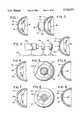
- FIG. 1is a side elevational view in section taken through the center of an eye showing the cornea, pupil and lens;
- FIG. 2is a side elevational view in section similar to that shown in FIG. 1 except that a thin layer has been removed from the front of the cornea, thereby separating the cornea into first and second opposed internal surfaces;
- FIG. 3is a diagrammatic side elevational view of the eye shown in FIG. 2 with a laser beam source, diaphragm and guiding mechanism being located adjacent thereto;
- FIG. 4is a side elevational view in section of an eye that has been treated by the apparatus shown in FIG. 3 with ablation conducted in an annular area spaced from the center of the internal surface on the cornea;
- FIG. 5is a front elevational view of the ablated cornea shown in FIG. 4;
- FIG. 6is a side elevational view in section showing the ablated cornea of FIGS. 4 and 5 with the thin layer previously removed from the cornea replaced onto the ablated area in the cornea, thereby increasing the curvature of the overall cornea;
- FIG. 7is a side elevational view in section of an eye which has been ablated in the central area of the internal surface on the cornea;
- FIG. 8is a front elevational view of the cornea having the central ablated portion shown in FIG. 7;
- FIG. 9is a side elevational view in section of the ablated cornea of FIGS. 7 and 8 in which the thin layer previously removed from the cornea is replaced over the ablated area, thereby reducing the curvature of the overall cornea;
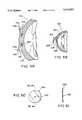
- FIG. 10is a front elevational view of the adjustable diaphragm shown in FIG. 3 used for directing the laser beam towards the eye;
- FIG. 11is a front elevational view of the guiding mechanism shown in FIG. 3 having a rotatable orifice of variable size formed therein, for directing the laser beam towards the eye in a predetermined pattern;
- FIG. 12is a right side elevational view of the guiding mechanism shown in FIG. 11;
- FIG. 13is a right side elevational view in section taken along line 13--13 in FIG. 11 showing the internal parts of the guiding mechanism;
- FIG. 14is a front elevational view of a modified guiding mechanism including a movable orifice
- FIG. 15is a diagrammatic side elevational view of a second modified guiding mechanism for a laser beam including a universally supported mirror and actuating motors used for moving the mirror and thereby guiding the laser beam in the predetermined pattern;
- FIG. 16is a diagrammatic side elevational view of a third modified guiding mechanism comprising a housing and a rotatable fiber optic cable;
- FIG. 17is an end elevational view of the housing and fiber optic cable shown in FIG. 16;
- FIG. 18is a diagrammatic side elevational view of a laser source, diaphragm and guiding mechanism for use in ablating the thin layer removed from the cornea, which is shown supported by a pair of cups;
- FIG. 19is a front elevational view of a live cornea which has been cut with a spatula to separate the central portion of the cornea into first and second opposed internal surfaces in accordance with the present invention
- FIG. 20is a side elevational view in section taken along line 20--20 of the cornea shown in FIG. 19;
- FIG. 21is a front elevational view of a cornea that has been cut as shown in FIG. 19 with ablation conducted in the central portion of the cornea by a laser;
- FIG. 22is a side elevational view in section taken along line 22--22 of the cornea shown in FIG. 21;
- FIG. 23is a side elevational view in section taken through the center of an eye showing the ablated cornea of FIGS. 19-22 with the fiber optic tip removed;
- FIG. 24is a side elevational view in section taken through the center of an eye showing the ablated cornea of FIGS. 19-23 in its collapsed position, thereby decreasing the curvature of the central portion of the cornea;
- FIG. 25is an enlarged, partial cross-sectional view of a cornea with a fiber optic tip cutting, separating and ablating the cornea into first and second opposed internal surfaces;
- FIG. 26is an enlarged, partial cross-sectional view of a cornea with a fiber optic tip having an angled end for ablating the cornea;
- FIG. 27is an enlarged, partial cross-sectional view of a cornea with a fiber optic tip having a bent end for ablating the cornea;
- FIG. 28is a front elevational view of a live cornea in which a plurality of radially extending cuts have been made with a spatula to separate the cornea at each of the radially extending cuts into first and second opposed internal surfaces in accordance with the present invention
- FIG. 29is a front elevational view of a cornea in which the radially extending cuts shown in FIG. 28 have been ablated to create a plurality of radially extending tunnels;
- FIG. 30is a side elevational view in section taken along line 30--30 of the cornea of FIG. 29 with the fiber optic tip removed;
- FIG. 31is a side elevational view in section taken along the center of an eye showing the ablated cornea of FIGS. 28-30 in its collapsed position, thereby decreasing the curvature of the central portion of the cornea;
- FIG. 32is a front elevational view of a live cornea in which a plurality of radially extending cuts have been made with a spatula to separate the cornea at each of the radially extending cuts into first and second opposed internal surfaces in accordance with the present invention
- FIG. 33is a side elevational view in section taken along line 33--33 of the cornea of FIG. 32 with the spatula removed;
- FIG. 34is a front elevational view of a cornea that has been radially cut as shown in FIGS. 32 and 33 with coagulation conducted at the ends of the radial cuts by a laser, thereby increasing the curvature of the central portion of the cornea;
- FIG. 35is a side elevational view in section taken along line 35--35 of the cornea of FIG. 34 with the laser removed and coagulation conducted at the ends of the radial cuts to increase the curvature of the central portion of the cornea;
- FIG. 36is an enlarged, partial cross-sectional view of a cornea with a drill tip removing tissue therefrom;
- FIG. 37is a front elevational view of a live cornea that has been cut to form an intrastromal pocket and showing a tool for injecting or implanting ocular material into the pocket;
- FIG. 38is an enlarged side elevational view in section taken through the center of an eye showing the intrastromal pocket over filled with ocular material thereby increasing the curvature of the central portion of the cornea;
- FIG. 39is an enlarged side elevational view in section taken through the center of an eye showing the intrastromal pocket partially filled with ocular material thereby decreasing the curvature of the central portion of the cornea;
- FIG. 40is an enlarged side elevational view in section taken through the center of an eye showing the intrastromal pocket completely filled with ocular material restoring the curvature of the central portion of the cornea to its original curvature;
- FIG. 41is a rear elevational view of an ocular implant or material in accordance with the present invention for implanting into a cornea;
- FIG. 42is a cross-sectional view of the ocular implant or material illustrated in FIG. 41 taken along section line 42--42;
- FIG. 43is an enlarged side elevational view in section taken through the center of an eye showing the intrastromal pocket with the ocular implant or material of FIGS. 41 and 42 therein for increasing the curvature of the central portion of the cornea;
- FIG. 44is an enlarged side elevational view in section taken through the center of an eye showing the intrastromal pocket with the ocular implant or material of FIGS. 41 and 42 therein for decreasing the curvature of the central portion of the cornea;
- FIG. 45is an enlarged side elevational view in section taken through the center of an eye showing the intrastromal pocket with the ocular implant or material of FIGS. 41 and 42 therein for maintaining the original curvature of the central portion of the cornea;
- FIG. 46is a front elevational view of a live cornea which has been cut to form a plurality of radial tunnels or pockets and showing a tool for injecting or implanting ocular material into the tunnels;
- FIG. 47is an enlarged side elevational view in section taken through the center of the eye showing the radial tunnels or pockets of FIG. 46 overfilled with ocular material thereby modifying the cornea and increasing its curvature;
- FIG. 48is an enlarged side elevational view in section taken through the center of the eye showing the radial tunnels or pockets of FIG. 46 underfilled with ocular material thereby modifying the cornea and decreasing its curvature;
- FIG. 49is an enlarged side elevational view in section taken through the center of the eye showing the radial tunnels or pockets of FIG. 46 completely filled with ocular material thereby modifying the cornea;
- FIG. 50is an enlarged side elevational view in section taken through the center of the eye showing one of the tunnels or pockets overfilled with ocular material to increase the curvature of a selected portion of the cornea and another tunnel or pocket underfilled to decrease the curvature of a selected portion of the cornea;
- FIG. 51is an enlarged side elevational view in section taken through the center of the eye showing one of the tunnels or pockets completely filled with ocular material to maintain a portion of the cornea at its original shape and another tunnel or pocket overfilled with ocular material to increase the curvature of a selected portion of the cornea;
- FIG. 52is an enlarged side elevational view in section taken through the center of the eye showing one of the tunnels or pockets completely filled with ocular material to maintain a portion of the cornea at its original shape and another tunnel or pocket unfilled to collapse or decrease the curvature of a selected portion of the cornea;
- FIG. 53is an enlarged side elevational view in section taken through the center of the eye showing one of the tunnels or pockets overfilled with ocular material to increase the curvature of a selected portion of the cornea and another tunnel or pocket unfilled to collapse or decrease the curvature of a selected portion of the cornea;
- FIG. 54is an exploded side elevational view in section taken through the center of an eye showing a thin layer or portion of the cornea completely removed from the live cornea and the ocular material or implant of FIGS. 41 and 42 positioned between the thin layer and the remainder of the live cornea;
- FIG. 55is an enlarged side elevational view in section taken through the center of the eye showing the ocular implant illustrated in FIGS. 41 and 42 implanted in the cornea with the thin layer of the cornea replaced over the ocular implant to increase the curvature of the cornea;
- FIG. 56is an enlarged side elevational view in section taken through the center of the eye showing the ocular implant illustrated in FIGS. 41 and 42 implanted in the cornea with the thin layer of the cornea replaced over the ocular implant to decrease the curvature of the cornea;
- FIG. 57is an enlarged side elevational view in section taken through the center of the eye showing the ocular implant illustrated in FIGS. 41 and 42 implanted in the cornea with the thin layer of the cornea replaced over the ocular implant to maintain the cornea's original curvature;
- FIG. 58is an enlarged side elevational view in cross section through the center of an eye showing a circular cut or groove in the cornea and the ocular implant of FIGS. 41 and 42 positioned between the separated internal layers, but before the separated internal layers are replaced or rejoined on the cornea;
- FIG. 59is a side elevational view in section through the center of the eye showing the outer surface of the cornea cut to form a flap having a portion still attached to the cornea to expose the intrastromal layers of the cornea;
- FIG. 60is a front elevational view of an ocular implant or material in accordance with the present invention for implanting within the intrastromal area of the cornea;
- FIG. 61is a cross-sectional view of the ocular implant or material illustrated in FIG. 60 taken along section line 61--61;
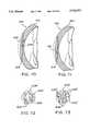
- FIG. 62is a front elevational view of the live cornea which has been cut with a tool to separate the central portion of the cornea into first and second opposed internal surfaces in accordance with the present invention
- FIG. 63is a side elevational view in longitudinal cross-section of the cornea shown in FIG. 62;
- FIG. 64is a front elevational view of the live cornea of FIG. 62 with a template inserted therein;
- FIG. 65is a side elevational view in longitudinal cross-section of the cornea shown in FIG. 64 illustrating the template positioned within the cornea;
- FIG. 66is front elevation view of the live cornea illustrated in FIGS. 62-65, but with the template inserted within the cornea and a laser beam emitting cable or fiber optic cable inserted therein to ablate at least one of the first and second opposed internal surfaces of the live cornea;
- FIG. 67is an enlarged, partial, side elevational view in section of the live cornea illustrated in FIG. 66 with the laser beam passing through a portion of the template to ablate one of the internal surfaces of the cornea;
- FIG. 68is front elevational view of the live cornea illustrated in FIGS. 62-67 after one of the internal surfaces has been completely ablated to form a circular pocket;
- FIG. 69is an enlarged side elevational view in cross section of the live cornea shown in FIG. 68 with a circular pocket formed therein and prior to collapsing thereof;
- FIG. 70is a side elevational view in cross section of the cornea shown in FIGS. 68 and 69, but after the ablated pocket has been collapsed to decrease the slope of the exterior surface of the cornea;
- FIG. 71is a side elevational view of the live cornea illustrated in FIG. 70, but with the ocular implant of FIGS. 60 and 61 inserted therein;
- FIG. 72is an alternative embodiment of a template for ablating at least one of the first and second opposed internal surfaces of the live cornea illustrated in FIGS. 62 and 63 so as to produce a ring-shaped ablation;
- FIG. 73is another alternative template for use in the live cornea illustrated in FIGS. 62 and 63 to ablate at least one of the first and second opposed internal surfaces in a plurality of radial lines.
- an eye 10comprising a cornea 12, a pupil 14, and a lens 16.
- the corneacan be modified in accordance with the invention to modify the refractive power of the combined corneal and lens system, to thereby correct vision. This is accomplished first by removing a thin layer 18 from the center part of a patient's live cornea 12 by cutting via a means for removing 19, such as a scalpel, via cutting, this thin layer being on the order of about 0.2 mm in thickness with the overall cornea being about 0.5 mm in thickness. Once the thin layer 18 is cut and removed from the cornea, it exposes first and second opposed internal surfaces 20 and 21 resulting from the surgical procedure.
- the exposed internal surface 20 on the remaining part of the corneathat is the target of the ablation via the excimer laser.
- the cut internal surface 21 on the removed thin layer of the corneacan also be the target of the laser, as illustrated in FIG. 18 and discussed in further detail hereinafter.
- the apparatus used in accordance with the inventioncomprises a source of a laser beam 22, an adjustable diaphragm 24, and a guiding mechanism 26, all aligned adjacent the eye 10 and supported on a suitable base 28.
- the laser beam source 22is advantageously an excimer laser of the argon-fluoride or krypton-fluoride type. This type of laser will photoablate the tissue of the cornea, i.e., decompose it without burning or coagulating which would unduly damage the live tissue. This ablation removes desired portions of the cornea and thereby allows for modification of the curvature thereof.
- the adjustable diaphragm 24 seen in FIGS. 3 and 10is essentially a conventional optical diaphragm with an adjustable central orifice 30 that can be increased or decreased in radial size by a manipulation of a lever 32 coupled to the diaphragm.
- the diaphragmis advantageously supported in a ring 34 that is in turn supported on a stand 36 on base 28.
- the material forming the diaphragmis opaque to laser light and thus when the laser is directed towards the diaphragm, it will pass therethrough only via the orifice 30.
- the diaphragm 24can be used in conjunction with the guiding mechanism 26, to be described in more detail hereinafter, to restrict the size of the laser beam passing to the guiding mechanism 26, or it can be used by itself to provide ablation of the exposed internal surface 20 of a cornea at its center.
- FIGS. 7-9a substantially disc-shaped ablated portion 38 is formed in the central exposed internal surface 20 by directing the laser beam 22 through orifice 30 of the diaphragm 24.
- the disc-shaped ablated portion 38can be varied in size.
- either a concave or convex ablated portioncan be formed, as desired.
- the previously removed thin layer 18is replaced onto the cornea in the ablated portion 38 and can be connected thereto via sutures 40.
- the ablated portion 38 as seen in FIG. 7is essentially a uniform cylindrical depression in the exposed internal surface 20, when the thin corneal layer 18 is replaced, the curvature of the cornea is decreased, thereby modifying the refractive power of the cornea and lens system.
- lever 32is used to vary the size of orifice 30, and is capable of being manipulated by hand or by a suitable conventional motor, which can be coordinated to provide an expansion or contraction of the orifice as necessary over time.
- the guiding mechanism 26can be utilized in addition to or in place of the diaphragm 24 to guide the laser light onto the cornea.
- This guiding mechanism 26is especially advantageous for forming an annular ablated portion 42 in surface 20 as seen in FIGS. 4-6 for increasing the overall curvature of the cornea.
- this annular ablated portion 42is spaced from the center of the exposed internal surface 20 and when the previously removed thin corneal layer 18 is replaced and sutured, the thin layer tends to be more convex, thereby modifying the overall curvature of the cornea.
- the guiding mechanism 26comprises a stand 44 supporting a ring 46, this ring having a radially inwardly facing recess 48 therein.
- a disc 50which is opaque to laser light, is located inside the ring and has a cylindrical extension 52 with an outwardly facing flange 54 rotatably and slidably received in the recess.
- On the cylindrical extension 52 which extends past ring 46is an exterior toothed gear 56 that is in engagement with a pinion 58 supported on a shaft 60 of a motor 62. Rotation of pinion 58 in turn rotates gear 56 and disc 50.
- the disc 50itself has an elongated rectangular orifice 64 formed therein essentially from one radial edge and extending radially inwardly past the center point of the disc. Adjacent the top and bottom of the orifice 64 are a pair of parallel rails 66 and 68 on which a masking cover 70, which is U-shaped in cross section, is slidably positioned. Thus, by moving the masking cover 70 along the rails, more or less of the orifice 64 is exposed to thereby allow more or less laser light to pass therethrough and onto the cornea. Clearly, the larger the orifice, the larger the width of the annular ablated portion 42 will be. By rotating the disc, the orifice 64 also rotates and thus the annular ablated portion 42 is formed.
- a modified guiding mechanism 72is shown which is similar to guiding mechanism 26 shown in FIGS. 11-13 except that the size of the orifice is not variable.
- the modified guiding mechanism 72is comprised of a ring 74 on a stand 76, an opaque disc 78 which is rotatable in the ring via a suitable motor, not shown, and a slidable masking cover 80.
- Disc 78has a rectangular orifice 82 extending diametrically there across with parallel rails 84 and 86 on top and bottom for slidably receiving the masking cover 80 thereon, this cover being U-shaped for engagement with the rails.
- the masking cover 80has its own orifice 88 therein which aligns with orifice 82 on the disc. Thus, by sliding the masking cover 80 along the rails of the disc, the location of the intersection of orifice 88 and orifice 82 can be varied to vary the radial position of the overall through orifice formed by the combination of these two orifices. As in guiding mechanism 26, the masking cover 80 and disc 78 are otherwise opaque to laser light except for the orifices.
- a second modified guiding mechanism 90for directing laser light from laser beam source 22 to the cornea 12 along the desired predetermined pattern.
- This guiding mechanism 90comprises a mirror 92 universally supported on a stand 94 via, for example, a ball 96 and socket 98 joint.
- This mirror 92can be pivoted relative to the stand through the universal joint by means of any suitable devices, such as two small piezoelectric motors which engage the mirror at 90° intervals.
- a piezoelectric motor 100having a plunger 102 coupled thereto and engaging the rear of the mirror can be utilized with a spring 104 surrounding the plunger and maintaining the mirror in a null position.
- the motor 100is rigidly coupled to a base 106 via a stand 108.
- the second piezoelectric motorcan be located so that its plunger engages the rear of the mirror 90° from the location of motor 100.
- the mirror 92can be fully rotated in its universal joint to direct the laser beam from source 22 onto the cornea 12 to ablate the cornea in a predetermined pattern.
- a third modified guiding mechanism 111for ablating a cornea 12 via directing laser light from laser source 22.
- This modified guiding mechanism 111basically comprises a cylindrical housing 113 having an opaque first end 115 rotatably receiving the end of a fiber optic cable 117 therein.
- the second end 119 of the housingcomprises a rotatable opaque disc having a flange 121 engaging the housing and an external gear 123 which in turn engages pinion 125, which is driven via shaft 127 and motor 129.
- rotation of the pinionresults in rotation of gear 123 and thus the opaque second end 119 of the housing.
- This second end 119has a diametrically oriented rectangular orifice 131 therein which receives the other end of the fiber optic cable 117 therein. That end of the fiber optic cable is either dimensioned so that it fits fairly tightly into the orifice or there is an additional suitable assembly utilized for maintaining the fiber optic cable end in a predetermined position in the orifice during rotation of the second end. However, this end would be movable radially of the orifice to change the position of the annular ablated portion formed by utilizing this guiding mechanism.
- the inner surface 133 of the removed thin corneal layer 18can be ablated utilizing the apparatus shown in FIG. 18.
- the apparatus of FIG. 18can be used on an eye bank cornea removed from the eye and then positioned in the patient's eye to modify the curvature of the patient's combined corneal structure.
- This apparatusas before includes the source of the laser light 22, an adjustable diaphragm 24, and a guiding mechanism 26.
- an assembly 134is utilized to support the rather flimsy removed thin corneal layer.
- This assembly 134comprises a pair of laser light transparent cups 136 and 138 that are joined together in a sealing relationship via clamps 140 and engage therebetween the outer periphery of the thin corneal layer 18.
- Each of the cupshas an inlet pipe 142, 144 for injecting pressurized air or suitable fluid into each via pumps 146 and 148.
- the thin corneal layer 18is maintained in the desired curvature so that the laser beam can provide a precise ablated predetermined pattern therein.
- the pressure on the right hand side of the thin layeris slightly greater than that on the left hand side.
- the thin corneal layer 18is suitably ablated as desired, it is replaced on the exposed internal surface 20 of the cornea and varies the curvature of the overall cornea as described above and illustrated in FIGS. 4-9.
- Eye 110includes a cornea 112, a pupil 114, and a lens 116, and is treated in accordance with the present invention without freezing the cornea.
- Correction of myopiacan be achieved by decreasing the curvature of the outer surface of cornea 112 (i.e., flattening the central portion of the cornea). This is accomplished by first cutting an incision 118 into the epithelium of cornea 112. Incision 118 may be curved or straight, and is preferably about 2.0-3.0 mm long and about 3.0-6.0 mm away from the center of cornea 112. A laser or spatula (i.e., a double-edge knife) may be used to make incision 118 in cornea 112.
- a spatula 120is inserted into incision 118 to separate an internal area of live cornea 112 into first and second opposed internal surfaces 122 and 124, thereby creating an intrastromal or internal pocket 126.
- First internal surface 122faces in the posterior direction of eye 110
- second internal surface 124faces in the anterior direction of eye 110, and both of these surfaces extend radially relative to the center of the cornea.
- pocket 126is created by moving spatula 120 back and forth within an intrastromal area of cornea 112. It is important when creating pocket 126 to keep spatula 120 in substantially a single plane and substantially tangential to the cornea's internal surfaces to prevent intersecting and rupturing the descemet or Bowman's membrane.
- spatula 120is about 3.0-12.0 mm long with a thickness of about 0.1-1.0 mm, and a width of about 0.1-1.2 mm.
- Spatula 120may be slightly curved, as seen in FIG. 20, or may be straight.
- spatula 120is shown in FIGS. 19 and 20 for separating the internal surfaces of cornea 112
- a fiber optic cable coupled to a laser beam sourcemay be used instead of spatula 120 to separate cornea 112 into first and second opposed internal surfaces 122 and 124.
- the laser beam emitted from tip 130may be directed upon either first internal surface 122, second internal surface 124, or both, and removes three-dimensional portions therefrom via ablation.
- the fiber optic cablecan be solid or hollow as desired.
- the laser source for fiber optic cable 132is advantageously a long wavelength, infrared laser, such as a CO 2 , an erbium or holmium laser, or a short wavelength, UV-excimer laser of the argon-fluoride or krypton-fluoride type. This type of laser will photoablate the intrastromal tissue of the cornea, i.e., decompose it without burning or coagulating.
- FIGS. 25-27illustrate three different configurations of the tip of a fiber optic cable for ablating the cornea.
- tip 130has a substantially straight end for directing the laser beam parallel to the tip.
- tip 130'has an end with an angled surface for directing the laser beam at an acute angle of preferably 45° relative to the tip to aid in ablating the cornea as desired.
- tip 130"has a curved end for bending the laser beam to aid ablating the cornea as desired.
- cornea 112is shown with the substantially disc-shaped cavity 126' formed at the center of cornea 112 just after tip 130 has been removed and prior to cornea 112 collapsing or flattening.
- the disc-shaped cavity 126'can be varied in size and shape, depending upon the amount of curvature modification needed to correct the patient's eyesight. Accordingly, any three-dimensional intrastromal area of the cornea may be removed to modify the cornea as desired.
- the intrastromal area removedcan be uniform or non-uniform. For example, more material can be removed from the periphery of the cornea than from the center portion. Alternatively, more material can be removed from the center portion than from the peripheral area. The removal of peripheral portions of the cornea result in an increase of the curvature of the center portion of the cornea after the collapse of the peripheral area.
- the ablated cavity 126'then collapses under normal eye pressure to recombine ablated first and second internal surfaces 122 and 124 together.
- This collapsing and recombining of the intrastromal area of the corneadecreases the curvature of the central portion of cornea 112 from its original shape shown in broken lines to its new shape as seen in FIG. 24.
- the ablated surfacesheal and grow back together, resulting in a permanent modification of the cornea's curvature.
- an eye 210is shown for the treatment of myopia in accordance with another embodiment of the present invention, and includes a cornea 212, a pupil 214, and a lens 216, the cornea being treated without freezing it.
- correction of myopiais accomplished by first making a plurality of radially directed intrastromal incisions 218 with a flat pin or blade spatula 220. These incisions 218 separate the cornea 218 into first and second opposed internal surfaces 222 and 224 at each of the incisions 218. First internal surfaces 222 face in the posterior direction of eye 210, while second internal surfaces 224 face in the anterior direction of eye 210, and both extend radially relative to the center of the cornea.
- Spatula 220may have a straight or curved blade with a maximum diameter of about 0.1-0.2 mm. A laser may be used instead of spatula 220 to make incisions 218, if desired.
- Incisions or unablated tunnels 218extend generally radially towards the center of cornea 212 from its periphery. Preferably, incisions 218 stop about 3.0 mm from the center of cornea 212, although incisions 218 may extend to the center of cornea 212, depending upon the degree of myopia. Incisions 218 will normally extend about 3.0-10.0 mm in length, again depending on the amount of change desired in curvature of cornea 112. While only radial incisions have been shown, it will be apparent to those skilled in the art that the incisions may be non-radial, curved, or other shapes. When creating incisions 218, it is important to keep the spatula 220 in substantially a single plane so as not to intersect and puncture the descemet or Bowman's membrane.
- a fiber optic cable tip 230 coupled to a fiber optic cable 232 and a laseris then inserted into each of the incisions 218 for ablating tunnels 226 to the desired size.
- the laser beam emitted from tip 230may be directed upon either first internal surface 222, second internal surface 224, or both for ablating tunnels 226 and removing three-dimensional portions from these surfaces.
- the laser source for cable 232is advantageously similar to the laser source for cable 132 discussed above.
- FIGS. 30 and 31a pair of ablated tunnels 226 are shown.
- cornea 212is shown with ablated tunnels 226 just after tip 230 has been removed and prior to tunnels 226 collapsing or flattening.
- cornea 212is shown after ablated tunnels 226 have collapsed to recombine first and second internal surfaces 222 and 224, thereby flattening cornea 212.
- this collapsing and recombining of the intrastromal area of the corneadecreases the curvature of the central portion of cornea 212 from its original shape shown in broken lines to its new shape as seen in FIG. 31.
- Thisallows the outer surface of the cornea to relax, i.e., decrease surface tension, thereby permitting flattening of the cornea.
- Eye 310is shown for the treatment of hyperopia in accordance with another embodiment of the present invention.
- Eye 310includes a cornea 312, a pupil 314, and a lens 316.
- Correction of hyperopiacan be achieved by increasing the curvature of the outer surface of cornea 312 (i.e., making the central portion of the cornea more curved), without freezing the cornea.
- Tunnels 318extend substantially radially towards the center of cornea 312. While eight equally spaced, radial tunnels 318 are shown, it will be apparent to those skilled in the art that more or fewer tunnels with varying distances apart may be made, depending upon the amount of curvature modification needed.
- the initial step of making incisions or tunnels 318 of FIGS. 32-35is similar to the initial step of making incisions 218 of FIGS. 28-31. Accordingly, spatula 320 is similar to spatula 220 discussed above. Likewise, a laser may be used to make incisions or tunnels 318 instead of spatula 320.
- a fiber optic cable tip 330 extending from fiber optic cable 332is inserted into each tunnel 318 to direct a laser beam on either first internal surface 322, second internal surface 324, or both internal surfaces to coagulate an intrastromal portion of cornea 312.
- a point 326 at the end of each of the tunnels 318is coagulated.
- coagulation points 326lie substantially on the circumference of a circle concentric with the center of cornea 312. The size of the circle forming coagulation points 326 depends upon the amount of curvature modification needed. Likewise, the number of coagulation points and their positions in the cornea depend upon the desired curvature modification needed.
- Coagulating intrastromal points of the cornea 312, such as coagulation points 326, with a lasercauses those points of the cornea, and especially the collagen therein, to heat up and shrink.
- This localized shrinkage of the intrastromal portion of the corneacauses the outer surface of the cornea to be tightened or pulled in a posterior direction at each of the coagulation points, and thereby causes an increase in the overall curvature of the cornea as seen in FIG. 35.
- Coagulationrather than ablation, is accomplished by using a laser having a wavelength which essentially cooks the corneal tissue and which is between the wavelengths associated with long infrared light and short ultraviolet light.
- a rotating drill tip 400 suitably coupled to a rotary or oscillating power sourcecan be used to ablate the tissue by cutting.
- any other suitable mechanical devicecan be used to remove the corneal tissue or form the cavities.
- a suitable evacuation devicesuch as a vacuum tube, can also be used to aid in evacuating from the cavity the tissue removed from the cornea.
- FIGS. 37-45a patient's live in situ eye 410 is shown for the treatment of hyperopia or myopia and/or improving a patient's vision by removing opaque portions of the cornea in accordance with the present invention.
- the eye 410 of FIGS. 37-40 and 43-45includes a cornea 412, a pupil 414 and a lens 416, and is treated in accordance with the present invention without freezing any portion of cornea 412.
- Correction of myopia and hyperopiacan be achieved by modifying the curvature of the outer surface of cornea 412, i.e., flattening the central portion of a cornea in the case of myopia or increasing the curvature in the case of hyperopia. This is accomplished by first cutting an incision 418 into the epithelium of cornea 412 as seen in FIG. 37.
- Incision 418may be curved or straight, and is preferably about 2.0-3.0 mm long and about 3.0-6.0 mm away from the center of cornea 412.
- a laser or a double-edge knifemay be used to make incision 418 in cornea 412.
- a spatula or laser probeis inserted into incision 418 to separate an internal area of live cornea 412 into first and second opposed internal surfaces 422 and 424, thereby creating an intrastromal or internal pocket 426 as in the previous embodiment of FIGS. 19-27.
- First internal surface 422faces in the posterior direction of eye 410
- second internal surface 424faces in the anterior direction of eye 410, and both of these surfaces extend radially relative to the center of the cornea 412.
- Pocket 426can have corneal tissue removed from either or both of internal surfaces 422 and 424.
- internal surfaces 422 and 424 of intrastromal pocket 426can be ablated or cut to define a cavity.
- the ablating or removing of the internal surfaces 422 and 424 of cornea 412is particularly desirable to remove opaque areas of cornea 412.
- the internal surfaces 422 and 424 of cornea 412can be removed by a scalpel or a diamond tipped drill similar to the embodiments discussed above.
- Pocket 426can be created by substantially the same method as previously discussed.
- incision 418 and pocket 426can be made in one single step by a laser or a cutting mechanism.
- none of the corneal tissuecan be removed from internal surfaces 422 and 424.
- Ocular material 428 or 430as used herein refers to transparent fluids or solids or any combination thereof.
- the ocular materialis a gel or fluid type material 428, which can be injected into pocket 426 via tool 450.
- tool 450is a needle for injecting ocular material 428 into pocket 426.
- the ocular materialis a flexible, resilient ring shaped member 430.
- ocular material 428 or 430can have either the same refractive index as the intrastromal tissue of cornea 412 or a different refractive index from the intrastromal tissue of cornea 412.
- the vision of the patientcan be modified by curvature modification and/or by changing the refractive index.
- the patient's visioncan be modified by merely removing opaque portions of the cornea and replacing them with ocular material with a refractive index the same as the intrastromal tissue of cornea 412.
- pocket 426can be overfilled, partially filled, or completely filled to modify the cornea as needed.
- the cavity or pocket 426can be filled completely with the ocular material to restore the normal curvature of cornea 426 as seen in FIG. 40.
- the amount of ocular material introduced to pocket 426can be increased to increase the curvature of the cornea from the original curvature to treat hyperopia as seen in FIG. 38.
- the amount of the ocular material introduced to pocket 426can be reduced to decrease the curvature or flatten cornea 412 from the original curvature to treat myopia as seen in FIG. 39. This method is suitable for correctly vision of 12 diopters or more.
- the internal surfaces 422 and 424 of pocket 426come together to encapsulate ocular material 428 within cornea 412. The surfaces heal and grow back together, resulting in a permanent modification of the cornea's curvature.
- the ocular material 428 injected into pocket 426can be any suitable material that is bio-compatible and does not visually interfere with the patient's eyesight.
- the ocular material 428 of FIGS. 38-40is a transparent gellable collagen such as gelatin in an injectable form which is available from various commercial sources as known in the art.
- the collagen to be used in the present inventionis a type I collagen.
- ocular material 428can be a transparent or translucent bio-compatible polymer gel such as a silicone gel or an injectable polymethylmethacrylate.
- ocular material 428is a polymeric material that is transparent, flexible, and hydrophilic.
- ocular material 428can be any suitable polymeric material.
- ocular material 28can be a flexible solid or semi-solid material as shown in the examples of FIGS. 41-45 discussed below regarding ocular material 430 which can be made from collagen or synthetic polymers such as acrylic polymers, silicones and polymethylmethacrylates.
- tool 450is utilized to insert ocular material or implant 430 through the small opening formed by incision 418 in the external surface of cornea 412, as seen in FIG. 37 so that ocular material or implant 430 can be implanted into pocket 426 and centered about the main optical axis of eye 410.
- Ocular material or implant 430is preferably a resilient, flexible member, which can be folded for insertion into pocket 426 through the small opening formed by incision 418.
- the ocular implant 430is made from a bio-compatible transparent material.
- ocular implant 430is made from any suitable transparent polymeric material.
- suitable materialsinclude, for example, collagen, silicone, polymethylmethacrylate, acrylic polymers, copolymers of methyl methacrylate with siloxanylalkyl methylacrylates, cellulose acetate butyrate and the like. Such materials are commercially available from contact lens manufacturers.
- optical grade siliconesare available from Allergan, Alcon, Staar, Chiron and Iolab.
- Optical grade acrylicsare available from Allergan and Alcon.
- a hydrogel lens material consisting of a hydrogel optic and polymethylmethacrylateis available from Staar.
- solid or semi-solid ocular material or implant 430can overfill, partial fill or completely fill pocket 426 to modify cornea 412 as needed. While ablation or removal of intrastromal tissue of pocket 426 is required for decreasing the curvature of cornea 412 as seen in FIG. 44, or for maintaining the original curvature of cornea 412 as seen in FIG. 45, such ablation or removal of intrastromal tissue of pocket 426 is not necessary for increasing the curvature of cornea 412. In any event, the amount of intrastromal tissue to be removed, if any, from pocket 426 depends on the shape of ocular material 430 and the desired resultant shape of cornea 412.
- ocular material or implant 430has a substantially annular ring shape with a center opening or circular hole 432. Center opening 432 allows intrastromal fluids to pass through ocular material or implant 430.
- ocular material 430has a circular periphery with an outer diameter in the range of about 3.0 mm to about 9.0 mm. Center opening 432 preferably ranges from about 1.0 mm to about 8.0 mm.
- the thickness of ocular material 430is preferably about 20 microns to about 1000 microns. It should be apparent from this disclosure that ocular material 430 can be a partial ring or a full ring with a slit. Moreover, ocular material 430 can be an oval ring.
- ocular material or implant 430has a planar face 434 and a curved face 436.
- Planar face 434forms a frustoconically shaped surface, which faces inwardly towards the center of eye 410 in a posterior direction of eye to contact internal surface 424 of pocket 426.
- Curved face 436can be shaped to form a corrective lens or shaped to modify the curvature cornea 412 as seen in FIGS. 43 and 44.
- ocular material 430can be shaped to replace opaque areas of cornea 412, which have been previously removed, and/or to form a corrective lens without changing the curvature of cornea 412 as seen in FIG. 45.
- center opening 432When center opening 432 is about 2.0 mm or smaller, center opening 432 acts as a pin hole such that the light passing through is always properly focused. Accordingly, ocular material 430 with such a small center opening 432 can be a corrective lens, which is not severely affected by center opening 432. However, when ocular material 430 has its center opening 432 greater than about 2.0 mm, then ocular material 430 most likely will have the same refractive index as the intrastromal tissue of cornea 412 for modifying the shape of cornea 412 and/or replacing opaque areas of the intrastromal tissue of cornea 412. Of course, all or portions of ocular material 430 can have a refractive index different from the intrastromal tissue of cornea 412 to correct astigmatisms or the like, when center opening 432 is greater than about 2.0 mm.
- the amount of curvature modification and/or the corrective power produced by ocular material 430can be varied by changing the thickness, the shape, the outer diameter and/or the size of the center opening 432.
- ocular material 430can be a ring with non-uniform cross-section in selected areas as necessary to correct the patient's vision.
- ocular material 430could be replaced with a plurality of separate solid or semi-solid ocular implants at selected locations within pocket 426 of cornea 412.
- Eye 510is shown for the treatment of hyperopia or myopia and/or improving vision by removing opaque portions of the cornea, in accordance with another embodiment of the present invention.
- Eye 510includes a cornea 512, a pupil 514, and a lens 516.
- cornea 512is treated without freezing it.
- correction of hyperopia or myopia or removal of opaque portionscan be accomplished by first making a plurality of radially directed intrastromal incisions 518 with a flat pin, laser or blade spatula similar to the procedure mentioned above discussing the embodiment of FIGS. 28-31.
- These incisions 518separate cornea 512 into first and second opposed internal surfaces 522 and 524, respectively, at each of the incisions 518.
- First internal surfaces 522face in the posterior direction of eye 510
- second internal surfaces 524face in the anterior direction of eye 510, and both extend radially relative to the center of cornea 512.
- Incisions or unablated tunnels 518extend generally radially towards the center of cornea 512 from its periphery. Preferably, incisions 518 stop about 3.0 mm from the center of cornea 512, although incisions 518 may extend to the center of cornea 512, depending upon the degree of hyperopia or myopia. Incisions 518 will normally extend about 3.0-10.0 mm in length, again depending on the amount of change desired in curvature of cornea 512. While only radial incisions have been shown, it will be apparent to those skilled in the art that the incisions may be non-radial, curved, or other shapes. When creating incisions 518, it is important to keep the spatula or laser in substantially a single plane so as not to intersect and puncture the descemet or Bowman's membrane.
- a fiber optic cable tip coupled to a fiber optic cable and a lasercan be optionally inserted into each of the incisions 518 for ablating tunnels 526 to the desired size, if needed or desired.
- the laser beam emitted from the tipmay be directed upon either first internal surface 522, second internal surface 524, or both for ablating tunnels 526 to sequentially and incrementally remove three-dimensional portions from these surfaces.
- the laser source for the cableis advantageously similar to the laser source for the cable as discussed above.
- a drill or other suitable micro-cutting instrumentscan be used to sequentially and incrementally remove portions of the cornea.
- ocular material 528refers to transparent fluids or solids or any combination thereof.
- ocular material 528is a gel or fluid type material, which can be injected into pockets 526 via tool 550.
- tool 550is a needle for injecting ocular material 528 into pockets 526.
- a solid implant or ocular materialmay be introduced into pockets 526.
- ocular material 528can have either a refractive index, which is different or the same as the intrastromal tissue of cornea 512 as needed and/or desired, whether the ocular material is a gel, a solid or any combination thereof.
- optical material 528 injected into the ablated tunnels 526expands the outer surface of cornea 512 outward to change or modify the curvature of the central portion of cornea 512 from its original shape shown in broken lines to its new shape shown in full lines.
- the various radial tunnels 526can be filled with ocular material 528 to overfill pockets 526 (FIG. 47), underfill pockets 526 (FIG. 48) or completely fill pockets 526 (FIG. 49).
- the curvature of cornea 512can be varied at different areas.
- selected tunnels 526can be overfilled or completely filled at selected areas, while other selected tunnels can be partially filled, completely filled or unfilled to collapse or decrease the curvature of cornea 512 at other selected areas as shown in FIGS. 50-53.
- the selective alteration of the curvature in different areas of the corneaare particularly desirable in correcting astigmatisms.
- the intrastromal areas of tunnels 526are preferably ablated by a laser or cut by a micro-cutting instrument for sequentially and incrementally removing three-dimensional portions of cornea 512 to form tubular pockets from tunnels 526.
- the incisions 518can be filled with ocular material without previously ablating or cutting the internal surfaces 522 and 524 of cornea 512 to expand the cornea 512 for increasing its curvature. Ablating the internal surfaces of the cornea is advantageous to remove opaque areas of the cornea which can then be filled with the ocular material.
- the amount of ocular material 528 introduced into the ablated areas of pockets 526can be less then the amount of ablated material to reduce the curvature of cornea 512.
- the amount of ocular material 528 introduced into the ablated areas of pockets 526can completely fill pockets 526 to retain the original curvature of cornea 512 as seen in FIGS. 49, 51 and 52.
- an eye 610is shown for treatment of hyperopia, myopia and/or removal of opaque portions in accordance with another embodiment of the invention using an implant or ocular material 630.
- the eye 610includes a cornea 612, a pupil 614 and a lens 616.
- the live eye 610is treated without freezing cornea 612 or any part thereof.
- a thin layer 618 of cornea 612is first removed from the center portion of a patient's live cornea 612 by cutting using a scalpel or laser.
- the thin layer 618is typically on the order of about 0.2 mm in thickness with overall cornea being on the order of about 0.5 mm in thickness.
- first and second opposed internal surfaces 622 and 624are the target of the ablation by the excimer laser.
- tissue from the internal surfaces 622 and/or 624can be removed by a mechanical cutting mechanism, or substantially no tissue is removed from the cornea.
- a disc-shaped portion 626is removed from internal surface 624 by a laser beam or other cutting mechanism.
- internal surface 624is shaped to include a concave annular portion 627.
- the method and laser apparatus as described above in the embodiment of FIGS. 1-10can be used for removing tissue from cornea 612 in substantially the same manner.
- an annular ring shaped implant or ocular material 630is placed on ablated portion 628 of cornea 612.
- the previously removed thin layer 618 of cornea 612is then replaced onto ablated portion 626 of cornea 612 to overlie implant or ocular material 630 and then reconnected thereto.
- the resulting corneacan have a modified curvature thereby modifying the refractive power of the cornea and lens system as seen in FIGS. 55 and 56, or the original curvature with opaque areas removed and/or modified refractive power as seen in FIG. 57.
- the ocular implant or material 630 in the embodiment shown in FIGS. 54-57has a substantially annular ring shape, and is substantially identical to the implant or ocular material 430 discussed above. Thus, implant 430 will not be illustrated or discussed in detail when referring to the procedures or methods of FIGS. 54-57. Similar to ocular material or implant 430, ocular material 630 can be a partial ring or a full ring with a slit.
- the outer diameter of ocular implant or material 630can be about 3-9 mm, while the inner opening 632 is generally about 1-8 mm.
- the thickness of ocular implant 630is preferably about 20 to about 1000 microns.
- Ocular implant 630has a planar face 644 forming a frustoconically shaped surface, which faces inwardly towards the center of eye 610 in a posterior direction of eye 610 to contact the exposed inner surface 620 of the cornea 612.
- the opposite face 646is preferably a curved surface facing in an anterior direction of eye 610 as shown.
- the ocular implant 630can be shaped to form a corrective lens or shaped to modify the curvature of the cornea. Similarly, the implant can be used to replace opaque areas of the cornea which have been previously removed by ablation or other means.
- ocular implant 630preferably has a substantially uniform shape and cross-section.
- ocular implant 630can be any suitable shape having either a uniform and/or non-uniform cross-section in selected areas as necessary to correct the patient's vision.
- an ocular implantcan be used having a circular or triangular cross section. In this manner, the curvature of a cornea can be modified at selected areas to correct various optical deficiencies, such as, for example, astigmatisms.
- Ocular implant 630can be a corrective lens with the appropriate refractive index to correct the vision of the patient.
- the ocular implant 630is made from a bio-compatible transparent material.
- ocular implant 630is made from any suitable transparent polymeric material.
- Suitable materialsinclude, for example, collagen, silicone, polymethylmethacrylate, acrylic polymers, copolymers of methyl methacrylate with siloxanylalkyl methylacrylates, cellulose acetate butyrate and the like. Such materials are commercially available from contact lens manufacturers. For example, optical grade silicones are available from Allergan, Alcon, Staar, Chiron and Iolab. Optical grade acrylics are available from Allergan and Alcon. A hydrogel lens material consisting of a hydrogel optic and polymethylmethacrylate is available from Staar.
- Hydrogel ocular implant lensescan be classified according to the chemical composition of the main ingredient in the polymer network regardless of the type or amount of minor components such as cross-linking agents and other by-products or impurities in the main monomer.
- Hydrogel lensescan be classified as (1) 2-hydroxyethyl methacrylate lenses; (2) 2-hydroxyethyl methacrylate-N-vinyl-2-pyrrolidinone lenses; 3) hydrophilic-hydrophobic moiety copolymer lenses (the hydrophilic components is usually N-vinyl-2-pyrrolidone or glyceryl methacrylate, the hydrophobic components is usually methyl methacrylate); and (4) miscellaneous hydrogel lenses, such as lenses with hard optical centers and soft hydrophilic peripheral skirts, and two-layer lenses.
- ocular implant 630can be elongated or arcuate shaped, disc shaped or other shapes for modifying the shape and curvature of cornea 612 or for improving the vision of eye 610 without modifying the curvature of cornea 612.
- ocular implant 630can be placed in the intrastromal area of the cornea 612 at a selected area to modify the curvature of the cornea and correct the vision provided by the cornea and lens system. In the embodiment shown in FIGS. 54-57, thin layer 618 of cornea 612 is completely removed to expose the internal surfaces 622 and 624 of cornea 612.
- FIG. 58An alternative method of implanting ocular material or implant 630 into an eye 710 is illustrated in FIG. 58. Specifically, ocular material or implant 630 is implanted into cornea 712 of eye 710 to modify the patient's vision. In particular, this method can be utilized for the treatment of hyperopia, myopia or removal of opaque portions of the cornea. As in the previous embodiments, the treatment of eye 510 is accomplished without freezing cornea 512 or any portion thereof.
- a ring or annular incision 718is formed in cornea 712 utilizing a scalpel, laser or any cutting mechanism known in the art.
- the scalpel, laser or cutting mechanismcan then be used to cut or ablate an annular-shaped intrastromal pocket 726 in cornea 712 as needed and/or desired. Accordingly, an annular groove is now formed for receiving ocular material or implant 630 which is discussed above in detail.
- annular groove formed by annular incision 718separates cornea 712 into first and second opposed internal surfaces 722 and 724.
- First internal surface 722faces in the posterior direction of eye 710, while second internal surface 724 faces in the anterior direction of eye 710.
- either internal surfaces 722 or 724can be ablated to make the annular groove or pocket 726 larger to accommodate ocular implant 630.
- cornea 712 with internal surface 722forms an annular flap 725, which is then lifted and folded away from the remainder of cornea 712 so that ocular implant of material 630 can be placed into annular pocket 726 of cornea 712 as seen in FIG. 58.
- corneal flap 725can be folded over ocular implant or material 630 and reconnected to the remainder of cornea 712 via sutures or the like. Accordingly, ocular implant or material 630 is now encapsulated within cornea 712.
- ocular implant or material 630can modify the curvature of the exterior surface of cornea 712 so as to either increase or decrease its curvature, or maintain the curvature of the exterior surface of cornea 712 at its original curvature.
- ocular implant or material 630can modify the patient's vision by changing the curvature of the cornea 712 and/or removing opaque portions of the cornea and/or by acting as a corrective lens within the cornea.
- FIG. 59Another embodiment of the present invention is illustrated utilizing ocular implant 630 in accordance with the present invention. More specifically, the method of FIG. 59 is substantially identical to the methods discussed above in reference to FIGS. 54-57, and thus, will not be illustrated or discussed in detail herein. Rather, the only significant difference between the methods discussed regarding FIGS. 54-57 and the method of FIG. 59 is that the thin layer 816 of FIG. 59 is not completely removed from cornea 812 of eye 810.
- thin layer 818 of cornea 812is formed by using a scalpel or laser such that a portion of layer 818 remains attached to the cornea 812 to form a corneal flap.
- the exposed inner surface 820 of layer 818 or the exposed internal surface 824 of the corneacan be ablated or cut with a laser or cutting mechanism as in the previous embodiments to modify the curvature of the cornea.
- Ocular implant 630can then be placed between internal surfaces 820 and 824 of cornea 812. The flap or layer 818 is then placed back onto the cornea 812 and allowed to heal. Accordingly, ocular implant 630 can increase, decrease or maintain the curvature of eye 810 as needed and/or desired as well as remove opaque portions of the eye.
- ocular implant or material 930in accordance with the present invention is illustrated for treatment of hyperopia or myopia.
- ocular implant or material 930is a disk shape member, which is as thin as paper or thinner.
- Ocular implant or material 930includes a center opening 932 for allowing intrastromal fluids to pass between either sides of ocular implant or material 930.
- ocular implant or material 930is constructed of a suitable transparent polymeric material utilizing diffractive technology, such as a Fresnel lens, which can be utilized to correct the focus of the light passing through the cornea by changing the refractive power of the cornea.
- ocular implant or material 930is very thin, i.e., as thin as paper or thinner, the exterior surface of the cornea will substantially retain its original shape even after ocular implant or material 930 is inserted into the cornea. Even if there is some change in the cornea, this change can be compensated by the refractive powers of the ocular implant or material 930.
- Ocular implant or material 930can be inserted into the cornea in any of the various ways disclosed in the preceding embodiments.
- ocular implant or material 930can be inserted through a relatively small opening formed in the cornea by folding the ocular implant or material 930 and then inserting it through the small opening and then allowing it to expand into a pocket formed within the intrastromal area of the cornea.
- a thin layer or flapcould be created for installing ocular implant or material 930 as discussed above.
- the outer diameter of ocular implant or material 930is preferably in the range of about 3.0 mm to about 9.0 mm, while center opening 932 is preferably about 1 mm to about 8.0 mm depending upon the type of vision to be corrected.
- ocular implant 930can be utilized to correct hyperopia and/or myopia when using a relatively small central opening 932 such as in the range of to about 1.0 mm to about 2.0 mm. However, if the opening is greater than about 2.0 mm, then the ocular implant or material 930 is most likely designed to correct imperfections in the eye such as to correct stigmatisms.
- the ocular implant 930In the event of astigmatism, only certain areas of the ocular implant 930 will have a refractive index which is different from the intrastromal tissue of the cornea, while the remainder of ocular implant or material 930 has the same refractive index as the intrastromal tissue of the cornea.
- ocular implant 930is made from a biocompatible transparent material which is resilient such that it can be folded and inserted through a small opening in the cornea and then allowed to expand back to its original shape when received within a pocket in the cornea.
- suitable materialsinclude, for example, substantially the same set of materials discussed above when referring to ocular implant or material 430 or 630 discussed above.
- FIGS. 62-73various methods in accordance with the present invention will be discussed for modifying a patient's live eye 1010 to correct the patient's vision.
- these methodsemploy many of the procedures of the prior discussed method for the treatment of hyperopia, myopia and/or improving a patient's vision by removing opaque portions of the cornea in accordance with the present invention. Accordingly, many of the prior procedures and illustrations previously mentioned herein will be used to describe the procedures of FIGS. 62-73.
- the procedures for modifying eye 1010 of FIGS. 62-71are accomplished by treating the intrastromal areas of cornea 1012. These procedures can include incrementally and sequentially ablating or removing three-dimensional portions of the intrastromal area of cornea 1012 and/or inserting ocular material 428, 430, 528, 630 or 930, as discussed above in the preceding embodiments.
- the first step of the procedureis to create an opening or incision 1018 into the epithelia of cornea 1012 as seen in FIGS. 62 and 63.
- Incision 1018may be curved or straight and is preferably 2.0 mm to 4.0 mm long and about 3.0 mm to about 6.0 mm away from the center of cornea 1012.
- the size and location of incision 1018depends upon the desired correction of cornea 1012. In other words, a pluralityof incisions could be made if need or desired in accordance with the present invention.
- Incision 1018 or incisionscan be made in cornea 1012 via a tool 1020, which can be any suitable instrument such as a fiber optic cable emitting in a laser beam, a scalpel, or a diamond tip micro drill.
- incision 1018is made, tool 1020 is inserted into the intrastromal area of cornea 1012 via incision 1018 to separate an internal area of live cornea 1012 into first and second opposed internal surfaces 1022 and 1024 to create an intrastromal or internal pocket 1026 as in the previous embodiments of FIGS. 19-27.
- Incision 1018 and pocket 1026can be made in one single step by a laser or cutting mechanism, or in two steps as needed and or desired.
- internal surface 1022faces in the posterior direction of eye 1010
- second internal surface 1024faces in the anterior direction of eye 1010, and both of these surfaces extend radially relative to the center of cornea 1012.
- Pocket 1026can have its intrastromal tissue removed from either or both of internal surfaces 1022 and 1024.
- internal surfaces 1022 and 1024 of intrastromal pocket 1026can be ablated or cut via tool 1020 to define a cavity.
- the ablating or removal of the internal surfaces 1022 and 1024 of the corneais particularly desirable to remove opaque areas of cornea 1012.
- the removal of the intrastromal tissue from internal surfaces 1022 and 1024can be accomplished by either a diamond tipped drill similar to FIG. 36 or via a laser beam-emitting cable such as a fiber optic cable similar to FIGS. 25-27.
- a template 1028can be utilized to ablate internal surfaces 1022 and/or 1024 as seen in FIGS. 66 and 67.
- Template 1028is preferably a flexible, resilient member including a laser beam transmitting portion 1030 and a laser beam blocking portion 1032 such that when the laser beam is directed onto the template, the laser beam passes through the laser beam transmitting portion 1030 but does not pass through the laser beam blocking portion 1032.
- template 1028is circular with laser beam transmitting portion 1030 being substantially a disc-shaped member and laser beam blocking portion 1032 being ring-shaped and surrounding laser beam transmitting portion 1030. Accordingly, when the laser beam is directed onto template 1030, a disc-shaped portion is ablated from cornea 1012 as illustrated in FIGS. 67-69.
- template 1028can have a variety of shapes with laser beam transmitting portion 1030 and laser beam blocking portion 1032 being shaped to form any desired predetermined pattern for ablating the internal surfaces of 1022 and/or 1024 of cornea 1012.
- laser beam transmitting portion 1030can be merely a cutout in template 1028.
- template 1028can have slits to assist in the insertion of template 1028 into pocket 1026.
- FIGS. 72 and 73Examples of other possible template configurations are shown in FIGS. 72 and 73 for controlling the ablation of cornea 1012.
- Template 1028'has a ring-shaped laser beam transmitting portion 1030' and a laser beam blocking portion 1032' surrounding portion 1030'
- Template 1028'also has a slit 1034' for aiding in the insertion of template 1028' into cornea 1012.
- FIG. 73illustrates a template 1028", which has a plurality of radially extending lines forming the laser beam transmitting portion 1030" and a laser beam blocking portion 1032" surrounding portion 1030".
- the template to be used with the procedures of this inventionmay have a variety of shapes, including but not limited to partial disc shapes, partial ring shapes, irregular shapes, to obtain the desired ablation pattern.
- template 1028Since template 1028 must be inserted through the relatively small opening or incision 1018, template 1028 must be able to be collapsed, e.g., folded or rolled, to fit through opening or incision 1018. Accordingly, template 1028 is created from a flexible resilient material, which can be collapsed for insertion into cornea 1012 via opening 1018 such that it can be easily restored to its original shape once in pocket 1026. Examples of various flexible materials include the same materials used for ocular implant 430, discussed above. By providing template 1028 with one or more slits, template 1028 can be easily collapsed for insertion into pocket 1026.
- cornea 1012is left alone for a predetermined period of time such as twenty-four hours to about forty-eight hours to allow the cornea to obtain its new refractive powers. This predetermined period could be longer, e.g., up to one month or even slightly longer.
- the cornea 1012is examined to determine how the cornea needs to be further modified to obtain the desired vision, if any further modification is needed.
- the pocket 1026 and the incision 1018will not have time to completely heal such that the surgeon can further ablate the internal surfaces 1022 and/or 1024 of cornea 1012 and/or insert one of the previously ocular materials 428, 430, 528, 630 or 930, or any of the variations thereof as previously discussed above.
- the surgeoncan further ablate cornea 1012 as necessary through small opening 1018 or insert the desired ocular material to create the desired further modification.
- the surgeoncan insert one ocular implant and then examine the refractive power of cornea 1012 to determine if that is the correct ocular implant. If not, the surgeon can remove that ocular implant and insert another ocular implant. This procedure can be continued until the correct ocular implant is inserted into cornea 1012 via opening 1018. In other words, this procedure is somewhat similar to the eye examination procedure for receiving glasses or contact lenses, but wherein the surgeon is actually replacing lenses within a pocket or pockets of a cornea.
- Such an irrigation stepcan be performed as many times as necessary in this procedure and at various times in the procedure as needed and/or desired.
- FIG. 71illustrates cornea 1012 with ocular implant 930 inserted into pocket 1026.
- ocular implant 930is preferably a suitable transparent polymeric material utilizing diffractive technology, such as a Fresnel lens, which can be utilized to correct the focus of the light passing through the cornea by changing the refractive power of the cornea.
- the ocular implant 930is particularly seen in FIG. 60 and 61 and has a center opening 932 therein.
- any one of the previously discussed ocular implants or materialscan be utilized.
- the gel or fluid of the previous embodimentsmay be injected within the pocket 1026, and then the surgeon will examine the eye to determine the new refractive power of the cornea resulting from the insertion of the ocular material.
- the surgeoncan adjust the ocular material by adding or subtracting predetermined amounts of the ocular material, and then reexamining the patient's eye until the desired refractive power of the cornea is obtained.
- the curvature of the corneacan be modified as needed by the insertion of the ocular material in the same manner as mentioned previously herein and as illustrated in the previously discussed figures.
- pocket 1026can be overfilled, partially filled, or completely filled to modify cornea 1012 as needed.
- the cavity or pocket 1026can be completely filled with the ocular material to restore the normal curvature of the cornea 1026 to result in a cornea with a curvature similar to cornea 428 as seen in FIG. 40.
- the amount of ocular material introduced to pocket 1026can be increased to increase the curvature of cornea 1012 from its original curvature to treat hypermyopia so as to result in a cornea with a curvature as seen in FIG. 38.
- the amount of ocular material introduced into pocket 1026can be reduced to decrease the curvature or flatten cornea 1012 from its original curvature to treat myopia so as to result in a cornea with a curvature as seen in FIG. 39.
- cornea 1012can result in various curvature modifications similar to those seen in FIGS. 43-45.
- the template of FIG. 72may be useful.
- the internal surfaces 1022 and 1024 of pocket 1026come together to encapsulate ocular material within cornea 1012. In other words, the surfaces heal and grow back together, resulting in permanent curvature modification of the cornea.
Landscapes
- Health & Medical Sciences (AREA)
- Ophthalmology & Optometry (AREA)
- Engineering & Computer Science (AREA)
- Biomedical Technology (AREA)
- Public Health (AREA)
- General Health & Medical Sciences (AREA)
- Veterinary Medicine (AREA)
- Heart & Thoracic Surgery (AREA)
- Vascular Medicine (AREA)
- Life Sciences & Earth Sciences (AREA)
- Animal Behavior & Ethology (AREA)
- Nuclear Medicine, Radiotherapy & Molecular Imaging (AREA)
- Surgery (AREA)
- Transplantation (AREA)
- Physics & Mathematics (AREA)
- Optics & Photonics (AREA)
- Cardiology (AREA)
- Oral & Maxillofacial Surgery (AREA)
- Laser Surgery Devices (AREA)
Abstract
Description
Claims (15)
Priority Applications (6)
| Application Number | Priority Date | Filing Date | Title |
|---|---|---|---|
| US08/552,624US5722971A (en) | 1995-10-20 | 1995-11-03 | Intrastromal corneal modification |
| US08/569,007US5964748A (en) | 1995-10-20 | 1995-12-07 | Intrastromal corneal modification |
| US08/940,202US6203538B1 (en) | 1995-11-03 | 1997-09-29 | Intrastromal corneal modification |
| US09/397,148US6217571B1 (en) | 1995-10-20 | 1999-09-16 | Intrastromal corneal modification |
| US09/758,263US20010027314A1 (en) | 1995-10-20 | 2001-01-12 | Intrastromal corneal modification via laser |
| US12/205,820US20090069817A1 (en) | 1995-10-20 | 2008-09-05 | Intrastromal corneal modification |
Applications Claiming Priority (2)
| Application Number | Priority Date | Filing Date | Title |
|---|---|---|---|
| US08/546,148US6221067B1 (en) | 1995-10-20 | 1995-10-20 | Corneal modification via implantation |
| US08/552,624US5722971A (en) | 1995-10-20 | 1995-11-03 | Intrastromal corneal modification |
Related Parent Applications (1)
| Application Number | Title | Priority Date | Filing Date |
|---|---|---|---|
| US08/546,148Continuation-In-PartUS6221067B1 (en) | 1995-10-20 | 1995-10-20 | Corneal modification via implantation |
Related Child Applications (1)
| Application Number | Title | Priority Date | Filing Date |
|---|---|---|---|
| US08/569,007Continuation-In-PartUS5964748A (en) | 1995-10-20 | 1995-12-07 | Intrastromal corneal modification |
Publications (1)
| Publication Number | Publication Date |
|---|---|
| US5722971Atrue US5722971A (en) | 1998-03-03 |
Family
ID=27068127
Family Applications (1)
| Application Number | Title | Priority Date | Filing Date |
|---|---|---|---|
| US08/552,624Expired - LifetimeUS5722971A (en) | 1995-10-20 | 1995-11-03 | Intrastromal corneal modification |
Country Status (1)
| Country | Link |
|---|---|
| US (1) | US5722971A (en) |
Cited By (111)
| Publication number | Priority date | Publication date | Assignee | Title |
|---|---|---|---|---|
| WO1998042409A1 (en)* | 1997-03-25 | 1998-10-01 | Sawusch Mark R | Method, implant, and apparatus for refractive keratoplasty |
| US5984914A (en)* | 1998-07-03 | 1999-11-16 | Cumming; J. Stuart | Apparatus and method for corneal keratotomy |
| US6019754A (en)* | 1998-10-29 | 2000-02-01 | Kawesch; Glenn | Method and apparatus for improving lasik flap adherence |
| US6138307A (en)* | 1999-05-06 | 2000-10-31 | Surgical Concepts, Inc. | Corneal intra-stromel prostheses |
| WO2000066022A1 (en)* | 1999-04-30 | 2000-11-09 | Visx, Incorporated | Method and system for ablating surfaces with partially overlapping craters having consistent curvature |
| US20010027314A1 (en)* | 1995-10-20 | 2001-10-04 | Peyman Gholam A. | Intrastromal corneal modification via laser |
| US6361560B1 (en) | 1998-12-23 | 2002-03-26 | Anamed, Inc. | Corneal implant and method of manufacture |
| EP1158936A4 (en)* | 1999-03-02 | 2002-05-22 | Gholam A Peyman | Intrastromal corneal modification |
| EP1159033A4 (en)* | 1999-03-02 | 2002-05-22 | Gholam A Peyman | A universal implant blank for midifying corneal curvature and methods of modifying corneal curvature therewith |
| US6436092B1 (en) | 2000-03-21 | 2002-08-20 | Gholam A. Peyman | Adjustable universal implant blank for modifying corneal curvature and methods of modifying corneal curvature therewith |
| US6458141B1 (en) | 2000-03-10 | 2002-10-01 | Gholam A. Peyman | Method and apparatus for creating a flap in the cornea and incisions or shrinkage under the flap to correct vision disorders |
| US20030018348A1 (en)* | 2001-07-23 | 2003-01-23 | Ioannis Pallikaris | Device for separating the epithelium layer from the surface of the cornea of an eye |
| WO2003005920A1 (en)* | 2001-07-13 | 2003-01-23 | Intralase Corp. | A method of creating stromal pockets for corneal implants |
| US6530916B1 (en)* | 1999-11-15 | 2003-03-11 | Visx, Incorporated | Uniform large area ablation system and method |
| US6551307B2 (en) | 2001-03-23 | 2003-04-22 | Gholam A. Peyman | Vision correction using intrastromal pocket and flap |
| US6589280B1 (en) | 2001-05-11 | 2003-07-08 | Jeffrey E. Koziol | Method for producing a multifocal corneal surface using intracorneal microscopic lenses |
| US6626941B2 (en) | 1998-12-23 | 2003-09-30 | Anamed, Inc. | Corneal implant and method of manufacture |
| US6702807B2 (en) | 2001-09-10 | 2004-03-09 | Minu, L.L.C. | Ablatable intracorneal inlay with predetermined refractive properties |
| US6786926B2 (en) | 2001-11-09 | 2004-09-07 | Minu, L.L.C. | Method and apparatus for alignment of intracorneal inlay |
| US20040220599A1 (en)* | 2001-07-23 | 2004-11-04 | Fos Holding S.A. | Device for separating the epithelium layer from the surface of the cornea of an eye |
| US20040243231A1 (en)* | 2001-05-11 | 2004-12-02 | Koziol Jeffrey E. | Intracorneal lens system having connected lenses |
| US20040260321A1 (en)* | 2002-12-19 | 2004-12-23 | Ming-Kok Tai | Apparatus and method for separating the epithelium layer from the cornea of an eye without corneal pre-applanation |
| US20040260320A1 (en)* | 2002-12-10 | 2004-12-23 | Lisk James R. | Disposable separator for separating the epithelium layer from the cornea of an eye |
| US20050014503A1 (en)* | 2000-11-17 | 2005-01-20 | Kabushiki Kaisha Toshiba | Scheme for registration and authentication in wireless communication system using wireless LAN |
| US20050033420A1 (en)* | 2003-05-28 | 2005-02-10 | Bruce A. Christie | Mask configured to maintain nutrient transport without producing visible diffraction patterns |
| US20050046794A1 (en)* | 2003-06-17 | 2005-03-03 | Silvestrini Thomas A. | Method and apparatus for aligning a mask with the visual axis of an eye |
| US20050080484A1 (en)* | 2002-09-13 | 2005-04-14 | Ocular Sciences, Inc. | Devices and methods for improving vision |
| US20050113911A1 (en)* | 2002-10-17 | 2005-05-26 | Peyman Gholam A. | Adjustable intraocular lens for insertion into the capsular bag |
| US20050113844A1 (en)* | 2000-09-12 | 2005-05-26 | Alok Nigam | System for packaging and handling an implant and method of use |
| US20050143717A1 (en)* | 2001-04-27 | 2005-06-30 | Peyman Gholam A. | Method of treatment of refractive errors using subepithelial or intrastromal corneal inlay with bonding coating |
| US20050149006A1 (en)* | 2001-11-07 | 2005-07-07 | Peyman Gholam A. | Device and method for reshaping the cornea |
| US6918904B1 (en) | 2001-11-07 | 2005-07-19 | Minu, L.L.C. | Method of reshaping the cornea by controlled thermal delivery |
| US20050177149A1 (en)* | 2001-11-07 | 2005-08-11 | Peyman Gholam A. | Method and apparatus for reshaping the cornea by controlled thermal delivery |
| US20050178394A1 (en)* | 2003-08-21 | 2005-08-18 | Intralens Vision, Inc. | Method for keratophakia surgery |
| US20050182489A1 (en)* | 2001-04-27 | 2005-08-18 | Peyman Gholam A. | Intraocular lens adapted for adjustment via laser after implantation |
| US20050182488A1 (en)* | 2001-04-27 | 2005-08-18 | Peyman Gholam A. | Implant and method for altering the refractive properties of the eye |
| US6949093B1 (en) | 2000-03-21 | 2005-09-27 | Minu, L.L.C. | Adjustable universal implant blank for modifying corneal curvature and methods of modifying corneal curvature therewith |
| US20050222679A1 (en)* | 2001-04-27 | 2005-10-06 | Peyman Gholam A | Bifocal implant and method for altering the refractive properties of the eye |
| US20050246015A1 (en)* | 2004-04-30 | 2005-11-03 | Troy Miller | Aspherical corneal implant |
| US20050246016A1 (en)* | 2004-04-30 | 2005-11-03 | Intralens Vision, Inc. | Implantable lenses with modified edge regions |
| US6989008B2 (en) | 2001-03-23 | 2006-01-24 | Minu Llc | Adjustable ablatable inlay |
| US20060036318A1 (en)* | 2004-08-13 | 2006-02-16 | Richard Foulkes | Method and insert for modifying eye color |
| US20060064077A1 (en)* | 2004-08-13 | 2006-03-23 | Peyman Gholam A | Method for correcting hyperopia and presbyopia using a laser and an inlay outside the visual axis of eye |
| US20060084949A1 (en)* | 2000-03-21 | 2006-04-20 | Peyman Gholam A | Method and apparatus for accommodating intraocular lens |
| US20060116762A1 (en)* | 2004-11-30 | 2006-06-01 | Xin Hong | Aspheric lenticule for keratophakia |
| US20060113054A1 (en)* | 2004-12-01 | 2006-06-01 | Silvestrini Thomas A | Method of making an ocular implant |
| US20060118263A1 (en)* | 2004-12-01 | 2006-06-08 | Silvestrini Thomas A | Method of making an ocular implant |
| US20060134170A1 (en)* | 2004-08-13 | 2006-06-22 | May Griffith | Vision enhancing ophthalmic devices and related methods and compositions |
| US20060155265A1 (en)* | 1995-03-20 | 2006-07-13 | Intralase Corp. | Method of corneal surgery by laser incising a contoured corneal flap |
| US20060184243A1 (en)* | 2004-10-22 | 2006-08-17 | Omer Yilmaz | System and method for aligning an optic with an axis of an eye |
| US20060203192A1 (en)* | 1999-03-01 | 2006-09-14 | David Miller | System and method for increasing the depth of focus of the human eye |
| US20060216329A1 (en)* | 2000-03-21 | 2006-09-28 | Peyman Gholam A | Drug delivery system and method |
| US20060235514A1 (en)* | 2005-04-14 | 2006-10-19 | Silvestrini Thomas A | Corneal optic formed of degradation resistant polymer |
| US20060235428A1 (en)* | 2005-04-14 | 2006-10-19 | Silvestrini Thomas A | Ocular inlay with locator |
| US20070088415A1 (en)* | 2001-11-07 | 2007-04-19 | Minu Llc | Method of treating the eye using controlled heat delivery |
| US20070100443A1 (en)* | 2005-10-27 | 2007-05-03 | Peyman Gholam A | Intraocular lens adapted for accommodation via electrical signals |
| WO2006096193A3 (en)* | 2005-03-03 | 2007-05-03 | Minu Llc | Adjustable optical element with multizone polymerization |
| US20070129797A1 (en)* | 2005-12-01 | 2007-06-07 | Revision Optics, Inc. | Intracorneal inlays |
| US20070142828A1 (en)* | 2001-11-07 | 2007-06-21 | Minu, Llc | Method and system for altering the refractive properties of the eye |
| US20070182920A1 (en)* | 2006-02-08 | 2007-08-09 | Coopervision, Inc. | Corneal Onlays and Related Methods |
| US20070203577A1 (en)* | 2006-02-24 | 2007-08-30 | Revision Optics, Inc. | Small Diameter Inlays |
| US20070219542A1 (en)* | 2006-03-15 | 2007-09-20 | Toru Yahagi | Surgical procedure and instrumentation for intrastromal implants of lens or strengthening materials |
| US20070239184A1 (en)* | 2006-04-10 | 2007-10-11 | Markus Gaeckle | Corneal epithelial pocket formation systems, components and methods |
| US20070255401A1 (en)* | 2006-05-01 | 2007-11-01 | Revision Optics, Inc. | Design of Inlays With Intrinsic Diopter Power |
| US20070265650A1 (en)* | 2001-07-23 | 2007-11-15 | Ioannis Pallikaris | Device for separating the epithelial layer from the surface of the cornea of an eye |
| WO2007135173A1 (en) | 2006-05-23 | 2007-11-29 | Albert Daxer | Corneal implant and method for correction of impaired vision in the human eye |
| US20070282313A1 (en)* | 2006-06-01 | 2007-12-06 | University Of Southern California | Method and apparatus to guide laser corneal surgery with optical measurement |
| US20080039769A1 (en)* | 2001-11-07 | 2008-02-14 | Minu Llc | Method of medical treatment using controlled heat delivery |
| US20080051772A1 (en)* | 2006-08-23 | 2008-02-28 | Szymon Suckewer | Method and Device for Cornea Reshaping by Intrastromal Tissue Removal |
| US20080243138A1 (en)* | 2007-03-28 | 2008-10-02 | Jon Dishler | Insertion system for corneal implants |
| US20080262610A1 (en)* | 2007-04-20 | 2008-10-23 | Alan Lang | Biomechanical design of intracorneal inlays |
| US20090069817A1 (en)* | 1995-10-20 | 2009-03-12 | Acufocus, Inc. | Intrastromal corneal modification |
| US20090076601A1 (en)* | 2006-03-16 | 2009-03-19 | Albert Daxer | Cornea Implant |
| US20090198325A1 (en)* | 2007-04-20 | 2009-08-06 | Keith Holliday | Corneal Inlay Design and Methods of Correcting Vision |
| US7585075B2 (en) | 2004-05-20 | 2009-09-08 | Forsight Labs, Llc | Corneal onlays and wavefront aberration correction to enhance vision |
| US20090306773A1 (en)* | 2008-06-04 | 2009-12-10 | Acufocus, Inc. | Opaque corneal insert for refractive correction |
| US20100087920A1 (en)* | 2008-10-07 | 2010-04-08 | Forsight Labs, Llc | Corneal Onlay Lenses and Related Methods for Improving Vision of Presbyopic Patients |
| US20100286770A1 (en)* | 2006-03-30 | 2010-11-11 | Mark Tomalla | Support Element for Compensating for Deformations of the Cornea of an Eye |
| US20110098790A1 (en)* | 2009-10-26 | 2011-04-28 | Albert Daxer | Methods for treating corneal disease |
| WO2011075091A1 (en)* | 2009-12-20 | 2011-06-23 | Faik Orucoglu | Filling material used in the reduction of corneal curvature |
| US20110218623A1 (en)* | 2004-04-30 | 2011-09-08 | Jon Dishler | Small Diameter Inlays |
| USD656526S1 (en) | 2009-11-10 | 2012-03-27 | Acufocus, Inc. | Ocular mask |
| US8409177B1 (en)* | 2005-10-13 | 2013-04-02 | Shui T. Lai | Intrastromal refractive surgery by inducing shape change of the cornea |
| US8469948B2 (en) | 2010-08-23 | 2013-06-25 | Revision Optics, Inc. | Methods and devices for forming corneal channels |
| US20130324984A1 (en)* | 2011-02-15 | 2013-12-05 | Wavelight Gmbh | Device and process for machining the cornea of a human eye with focused pulsed laser radiation |
| US8668735B2 (en) | 2000-09-12 | 2014-03-11 | Revision Optics, Inc. | Corneal implant storage and delivery devices |
| US9005280B2 (en) | 2000-09-12 | 2015-04-14 | Revision Optics, Inc. | System for packaging and handling an implant and method of use |
| US9005281B2 (en) | 2009-08-13 | 2015-04-14 | Acufocus, Inc. | Masked intraocular implants and lenses |
| US9204962B2 (en) | 2013-03-13 | 2015-12-08 | Acufocus, Inc. | In situ adjustable optical mask |
| US9271828B2 (en) | 2007-03-28 | 2016-03-01 | Revision Optics, Inc. | Corneal implant retaining devices and methods of use |
| US9345569B2 (en) | 2011-10-21 | 2016-05-24 | Revision Optics, Inc. | Corneal implant storage and delivery devices |
| US9427922B2 (en) | 2013-03-14 | 2016-08-30 | Acufocus, Inc. | Process for manufacturing an intraocular lens with an embedded mask |
| US9427311B2 (en) | 2009-08-13 | 2016-08-30 | Acufocus, Inc. | Corneal inlay with nutrient transport structures |
| US9539143B2 (en) | 2008-04-04 | 2017-01-10 | Revision Optics, Inc. | Methods of correcting vision |
| US9545303B2 (en) | 2011-12-02 | 2017-01-17 | Acufocus, Inc. | Ocular mask having selective spectral transmission |
| US9549848B2 (en) | 2007-03-28 | 2017-01-24 | Revision Optics, Inc. | Corneal implant inserters and methods of use |
| US9681800B2 (en) | 2005-10-27 | 2017-06-20 | The Arizona Board Of Regents On Behalf Of The University Of Arizona | Holographic adaptive see-through phoropter |
| WO2018063137A1 (en)* | 2016-09-27 | 2018-04-05 | Yichieh Shiuey | Systems, device, and method for cross-linking corneal tissue |
| US9943403B2 (en) | 2014-11-19 | 2018-04-17 | Acufocus, Inc. | Fracturable mask for treating presbyopia |
| US10004593B2 (en) | 2009-08-13 | 2018-06-26 | Acufocus, Inc. | Intraocular lens with elastic mask |
| US10555805B2 (en) | 2006-02-24 | 2020-02-11 | Rvo 2.0, Inc. | Anterior corneal shapes and methods of providing the shapes |
| US10583041B2 (en) | 2015-03-12 | 2020-03-10 | RVO 2.0 Inc. | Methods of correcting vision |
| US10687935B2 (en) | 2015-10-05 | 2020-06-23 | Acufocus, Inc. | Methods of molding intraocular lenses |
| US20200268505A1 (en)* | 2019-02-26 | 2020-08-27 | Avedro, Inc. | Bioresorbable corneal implants |
| US10835371B2 (en) | 2004-04-30 | 2020-11-17 | Rvo 2.0, Inc. | Small diameter corneal inlay methods |
| US11154191B2 (en)* | 2007-04-26 | 2021-10-26 | Carl Zeiss Meditec Ag | Cornea transplantation |
| US11364110B2 (en) | 2018-05-09 | 2022-06-21 | Acufocus, Inc. | Intraocular implant with removable optic |
| US11464625B2 (en) | 2015-11-24 | 2022-10-11 | Acufocus, Inc. | Toric small aperture intraocular lens with extended depth of focus |
| WO2023041623A1 (en) | 2021-09-17 | 2023-03-23 | Carl Zeiss Meditec Ag | Correcting the refraction of an eye by corneal modification |
| US11957569B2 (en) | 2019-02-28 | 2024-04-16 | Tissuecor, Llc | Graft tissue injector |
| US12090262B2 (en) | 2021-09-01 | 2024-09-17 | Tissuecor, Llc | Device and system for injecting biological tissue |
Citations (25)
| Publication number | Priority date | Publication date | Assignee | Title |
|---|---|---|---|---|
| US3982541A (en)* | 1974-07-29 | 1976-09-28 | Esperance Jr Francis A L | Eye surgical instrument |
| US4298004A (en)* | 1979-02-27 | 1981-11-03 | Schachar Ronald A | Surgical method for altering the curvature of the cornea of rabbits |
| US4452235A (en)* | 1982-01-04 | 1984-06-05 | Reynolds Alvin E | Method for corneal curvature adjustment |
| US4655774A (en)* | 1986-01-03 | 1987-04-07 | Choyce D Peter | Intra-corneal implant for correction of aniridia |
| US4665913A (en)* | 1983-11-17 | 1987-05-19 | Lri L.P. | Method for ophthalmological surgery |
| US4669466A (en)* | 1985-01-16 | 1987-06-02 | Lri L.P. | Method and apparatus for analysis and correction of abnormal refractive errors of the eye |
| US4676790A (en)* | 1985-09-25 | 1987-06-30 | Kern Seymour P | Method of manufacture and implantation of corneal inlays |
| US4678422A (en)* | 1985-11-12 | 1987-07-07 | York Kenneth K | Systems and methods for precise, accurate formation of products by photoablation |
| US4729372A (en)* | 1983-11-17 | 1988-03-08 | Lri L.P. | Apparatus for performing ophthalmic laser surgery |
| US4744360A (en)* | 1986-12-18 | 1988-05-17 | Bath Patricia E | Apparatus for ablating and removing cataract lenses |
| US4799931A (en)* | 1986-05-14 | 1989-01-24 | Lindstrom Richard L | Intracorneal lens |
| US4840175A (en)* | 1986-12-24 | 1989-06-20 | Peyman Gholam A | Method for modifying corneal curvature |
| US4903695A (en)* | 1988-11-30 | 1990-02-27 | Lri L.P. | Method and apparatus for performing a keratomileusis or the like operation |
| US4961744A (en)* | 1982-01-04 | 1990-10-09 | Keravision, Inc. | Holder for inserting corneal curvature adjustable ring |
| US5063942A (en)* | 1989-12-14 | 1991-11-12 | Corneal Contouring, Inc. | Method for surgically re-profiling the cornea |
| US5196026A (en)* | 1991-09-16 | 1993-03-23 | Chiron Ophthalmics, Inc. | Method of implanting corneal inlay lenses smaller than the optic zone |
| US5215104A (en)* | 1988-08-16 | 1993-06-01 | Steinert Roger F | Method for corneal modification |
| US5300118A (en)* | 1992-09-21 | 1994-04-05 | Keravision | Adjustable devices for corneal curvature adjustment |
| US5318044A (en)* | 1989-12-14 | 1994-06-07 | Corneal Contouring, Inc. | Method and apparatus for re-profiling the cornea to correct for hyperopia |
| US5318047A (en)* | 1992-01-14 | 1994-06-07 | Keravision Inc. | Method for corneal curvature variation |
| US5323788A (en)* | 1992-09-21 | 1994-06-28 | Keravision | Overlapping split ring device for corneal curvature adjustment |
| US5368604A (en)* | 1989-12-14 | 1994-11-29 | Corneal Contouring Inc. | Method and apparatus for surgically profiling the cornea using vacuum |
| US5391201A (en)* | 1992-10-02 | 1995-02-21 | Chiron Intraoptics, Inc. | Method of using a corneal ring inlay |
| US5403335A (en)* | 1992-04-10 | 1995-04-04 | Keravision, Inc. | Corneal vacuum centering guide and dissector |
| US5405384A (en)* | 1992-09-03 | 1995-04-11 | Keravision, Inc. | Astigmatic correcting intrastromal corneal ring |
- 1995
- 1995-11-03USUS08/552,624patent/US5722971A/ennot_activeExpired - Lifetime
Patent Citations (27)
| Publication number | Priority date | Publication date | Assignee | Title |
|---|---|---|---|---|
| US3982541A (en)* | 1974-07-29 | 1976-09-28 | Esperance Jr Francis A L | Eye surgical instrument |
| US4298004A (en)* | 1979-02-27 | 1981-11-03 | Schachar Ronald A | Surgical method for altering the curvature of the cornea of rabbits |
| US4452235A (en)* | 1982-01-04 | 1984-06-05 | Reynolds Alvin E | Method for corneal curvature adjustment |
| US4961744A (en)* | 1982-01-04 | 1990-10-09 | Keravision, Inc. | Holder for inserting corneal curvature adjustable ring |
| US4665913A (en)* | 1983-11-17 | 1987-05-19 | Lri L.P. | Method for ophthalmological surgery |
| US4729372A (en)* | 1983-11-17 | 1988-03-08 | Lri L.P. | Apparatus for performing ophthalmic laser surgery |
| US4669466A (en)* | 1985-01-16 | 1987-06-02 | Lri L.P. | Method and apparatus for analysis and correction of abnormal refractive errors of the eye |
| US4676790A (en)* | 1985-09-25 | 1987-06-30 | Kern Seymour P | Method of manufacture and implantation of corneal inlays |
| US4678422A (en)* | 1985-11-12 | 1987-07-07 | York Kenneth K | Systems and methods for precise, accurate formation of products by photoablation |
| US4655774A (en)* | 1986-01-03 | 1987-04-07 | Choyce D Peter | Intra-corneal implant for correction of aniridia |
| US4799931A (en)* | 1986-05-14 | 1989-01-24 | Lindstrom Richard L | Intracorneal lens |
| US4744360A (en)* | 1986-12-18 | 1988-05-17 | Bath Patricia E | Apparatus for ablating and removing cataract lenses |
| US4840175A (en)* | 1986-12-24 | 1989-06-20 | Peyman Gholam A | Method for modifying corneal curvature |
| US5215104A (en)* | 1988-08-16 | 1993-06-01 | Steinert Roger F | Method for corneal modification |
| US4903695A (en)* | 1988-11-30 | 1990-02-27 | Lri L.P. | Method and apparatus for performing a keratomileusis or the like operation |
| US4903695C1 (en)* | 1988-11-30 | 2001-09-11 | Lri L P | Method and apparatus for performing a keratomileusis or the like operation |
| US5063942A (en)* | 1989-12-14 | 1991-11-12 | Corneal Contouring, Inc. | Method for surgically re-profiling the cornea |
| US5318044A (en)* | 1989-12-14 | 1994-06-07 | Corneal Contouring, Inc. | Method and apparatus for re-profiling the cornea to correct for hyperopia |
| US5368604A (en)* | 1989-12-14 | 1994-11-29 | Corneal Contouring Inc. | Method and apparatus for surgically profiling the cornea using vacuum |
| US5196026A (en)* | 1991-09-16 | 1993-03-23 | Chiron Ophthalmics, Inc. | Method of implanting corneal inlay lenses smaller than the optic zone |
| US5336261A (en)* | 1991-09-16 | 1994-08-09 | Chiron Intraoptics, Inc. | Corneal inlay lenses |
| US5318047A (en)* | 1992-01-14 | 1994-06-07 | Keravision Inc. | Method for corneal curvature variation |
| US5403335A (en)* | 1992-04-10 | 1995-04-04 | Keravision, Inc. | Corneal vacuum centering guide and dissector |
| US5405384A (en)* | 1992-09-03 | 1995-04-11 | Keravision, Inc. | Astigmatic correcting intrastromal corneal ring |
| US5300118A (en)* | 1992-09-21 | 1994-04-05 | Keravision | Adjustable devices for corneal curvature adjustment |
| US5323788A (en)* | 1992-09-21 | 1994-06-28 | Keravision | Overlapping split ring device for corneal curvature adjustment |
| US5391201A (en)* | 1992-10-02 | 1995-02-21 | Chiron Intraoptics, Inc. | Method of using a corneal ring inlay |
Non-Patent Citations (10)
| Title |
|---|
| "Corneal Surgery" by L. Girard, The C.V. Mosby Publishing Company, London 1981 pp. 107-141. |
| "Epikeratophakia: Techniques, Complications, and Clinical Results" by Werblin, Ophthalmology, pp. 45-58. |
| "Keratomileusis and Keratophakia in the Surgical Correction of Aphakia" by Barraquer, Cataract Surgery and Special Techniques, pp. 270-289. |
| "Lamellar Corneal Stromectomy for the Operative Treatment of Myopia" by Tadeusz Krwawicz, Notes, Cases, Instruments-received in PTO Sep. 1986, pp. 828-833. |
| "Refractive Keratoplasty: Acute Morphologic Features," by Baumgartner et al, The CLAO Journal-Apr. 1985, vol. II, No. 2, pp. 163-169. |
| Corneal Surgery by L. Girard, The C.V. Mosby Publishing Company, London 1981 pp. 107 141.* |
| Epikeratophakia: Techniques, Complications, and Clinical Results by Werblin, Ophthalmology, pp. 45 58.* |
| Keratomileusis and Keratophakia in the Surgical Correction of Aphakia by Barraquer, Cataract Surgery and Special Techniques, pp. 270 289.* |
| Lamellar Corneal Stromectomy for the Operative Treatment of Myopia by Tadeusz Krwawicz, Notes, Cases, Instruments received in PTO Sep. 1986, pp. 828 833.* |
| Refractive Keratoplasty: Acute Morphologic Features, by Baumgartner et al, The CLAO Journal Apr. 1985, vol. II, No. 2, pp. 163 169.* |
Cited By (214)
| Publication number | Priority date | Publication date | Assignee | Title |
|---|---|---|---|---|
| US7892226B2 (en)* | 1995-03-20 | 2011-02-22 | Amo Development, Llc. | Method of corneal surgery by laser incising a contoured corneal flap |
| US20060155265A1 (en)* | 1995-03-20 | 2006-07-13 | Intralase Corp. | Method of corneal surgery by laser incising a contoured corneal flap |
| US20090069817A1 (en)* | 1995-10-20 | 2009-03-12 | Acufocus, Inc. | Intrastromal corneal modification |
| US20010027314A1 (en)* | 1995-10-20 | 2001-10-04 | Peyman Gholam A. | Intrastromal corneal modification via laser |
| US6171336B1 (en) | 1996-03-26 | 2001-01-09 | Mark R. Sawusch | Method, implant, and apparatus for refractive keratoplasty |
| WO1998042409A1 (en)* | 1997-03-25 | 1998-10-01 | Sawusch Mark R | Method, implant, and apparatus for refractive keratoplasty |
| EP1213998A4 (en)* | 1998-07-03 | 2005-07-27 | J Stuart Cumming | Apparatus and method for corneal keratotomy |
| US5984914A (en)* | 1998-07-03 | 1999-11-16 | Cumming; J. Stuart | Apparatus and method for corneal keratotomy |
| US6019754A (en)* | 1998-10-29 | 2000-02-01 | Kawesch; Glenn | Method and apparatus for improving lasik flap adherence |
| US6673112B2 (en) | 1998-12-23 | 2004-01-06 | Anamed, Inc. | Corneal implant and method of manufacture |
| US20020065555A1 (en)* | 1998-12-23 | 2002-05-30 | Alok Nigam | Corneal implant and method of manufacture |
| US6875232B2 (en) | 1998-12-23 | 2005-04-05 | Anamed, Inc. | Corneal implant and method of manufacture |
| US6632244B1 (en) | 1998-12-23 | 2003-10-14 | Anamed, Inc. | Corneal implant and method of manufacture |
| US6626941B2 (en) | 1998-12-23 | 2003-09-30 | Anamed, Inc. | Corneal implant and method of manufacture |
| US6607556B1 (en) | 1998-12-23 | 2003-08-19 | Anamed, Inc. | Corneal implant and method of manufacture |
| US6361560B1 (en) | 1998-12-23 | 2002-03-26 | Anamed, Inc. | Corneal implant and method of manufacture |
| US7404637B2 (en) | 1999-03-01 | 2008-07-29 | Boston Innovative Optics, Inc. | System and method for increasing the depth of focus of the human eye |
| US20090059168A1 (en)* | 1999-03-01 | 2009-03-05 | Boston Innovative Optics, Inc. | System and method for increasing the depth focus of the human eye |
| US20060203192A1 (en)* | 1999-03-01 | 2006-09-14 | David Miller | System and method for increasing the depth of focus of the human eye |
| US8752958B2 (en) | 1999-03-01 | 2014-06-17 | Boston Innovative Optics, Inc. | System and method for increasing the depth of focus of the human eye |
| US7404638B2 (en) | 1999-03-01 | 2008-07-29 | Boston Innovative Optics, Inc. | System and method for increasing the depth of focus of the human eye |
| US8343215B2 (en) | 1999-03-01 | 2013-01-01 | Acufocus, Inc. | System and method for increasing the depth of focus of the human eye |
| US20060274267A1 (en)* | 1999-03-01 | 2006-12-07 | David Miller | System and method for increasing the depth of focus of the human eye |
| EP1997530A1 (en)* | 1999-03-02 | 2008-12-03 | Peyman, Gholam A. | Intrastromal corneal modification |
| EP1159033A4 (en)* | 1999-03-02 | 2002-05-22 | Gholam A Peyman | A universal implant blank for midifying corneal curvature and methods of modifying corneal curvature therewith |
| EP1158936A4 (en)* | 1999-03-02 | 2002-05-22 | Gholam A Peyman | Intrastromal corneal modification |
| US6497701B2 (en)* | 1999-04-30 | 2002-12-24 | Visx, Incorporated | Method and system for ablating surfaces with partially overlapping craters having consistent curvature |
| WO2000066022A1 (en)* | 1999-04-30 | 2000-11-09 | Visx, Incorporated | Method and system for ablating surfaces with partially overlapping craters having consistent curvature |
| US6138307A (en)* | 1999-05-06 | 2000-10-31 | Surgical Concepts, Inc. | Corneal intra-stromel prostheses |
| EP1229856A4 (en)* | 1999-08-27 | 2002-10-16 | Anamed Inc | Corneal implant and method of manufacture |
| US6530916B1 (en)* | 1999-11-15 | 2003-03-11 | Visx, Incorporated | Uniform large area ablation system and method |
| US6458141B1 (en) | 2000-03-10 | 2002-10-01 | Gholam A. Peyman | Method and apparatus for creating a flap in the cornea and incisions or shrinkage under the flap to correct vision disorders |
| US6436092B1 (en) | 2000-03-21 | 2002-08-20 | Gholam A. Peyman | Adjustable universal implant blank for modifying corneal curvature and methods of modifying corneal curvature therewith |
| US8162927B2 (en)* | 2000-03-21 | 2012-04-24 | Gholam A. Peyman | Method and apparatus for accommodating intraocular lens |
| US6949093B1 (en) | 2000-03-21 | 2005-09-27 | Minu, L.L.C. | Adjustable universal implant blank for modifying corneal curvature and methods of modifying corneal curvature therewith |
| US20060216329A1 (en)* | 2000-03-21 | 2006-09-28 | Peyman Gholam A | Drug delivery system and method |
| EP1267998A4 (en)* | 2000-03-21 | 2011-01-12 | Gholam Ali Peyman | An adjustable universal implant blank for modifying corneal curvature and methods of modifying corneal curvature therewith |
| US7001374B2 (en) | 2000-03-21 | 2006-02-21 | Minu, L.L.C. | Adjustable inlay with multizone polymerization |
| US20060084949A1 (en)* | 2000-03-21 | 2006-04-20 | Peyman Gholam A | Method and apparatus for accommodating intraocular lens |
| US20050113844A1 (en)* | 2000-09-12 | 2005-05-26 | Alok Nigam | System for packaging and handling an implant and method of use |
| US8668735B2 (en) | 2000-09-12 | 2014-03-11 | Revision Optics, Inc. | Corneal implant storage and delivery devices |
| US9889000B2 (en) | 2000-09-12 | 2018-02-13 | Revision Optics, Inc. | Corneal implant applicators |
| US9005280B2 (en) | 2000-09-12 | 2015-04-14 | Revision Optics, Inc. | System for packaging and handling an implant and method of use |
| US7324805B2 (en) | 2000-11-17 | 2008-01-29 | Kabushiki Kaish Toshiba | Scheme for registration and authentication in wireless communication system using wireless LAN |
| US20050014503A1 (en)* | 2000-11-17 | 2005-01-20 | Kabushiki Kaisha Toshiba | Scheme for registration and authentication in wireless communication system using wireless LAN |
| US6551307B2 (en) | 2001-03-23 | 2003-04-22 | Gholam A. Peyman | Vision correction using intrastromal pocket and flap |
| US6989008B2 (en) | 2001-03-23 | 2006-01-24 | Minu Llc | Adjustable ablatable inlay |
| US20050182488A1 (en)* | 2001-04-27 | 2005-08-18 | Peyman Gholam A. | Implant and method for altering the refractive properties of the eye |
| US20050222679A1 (en)* | 2001-04-27 | 2005-10-06 | Peyman Gholam A | Bifocal implant and method for altering the refractive properties of the eye |
| US20050182489A1 (en)* | 2001-04-27 | 2005-08-18 | Peyman Gholam A. | Intraocular lens adapted for adjustment via laser after implantation |
| US20050143717A1 (en)* | 2001-04-27 | 2005-06-30 | Peyman Gholam A. | Method of treatment of refractive errors using subepithelial or intrastromal corneal inlay with bonding coating |
| US7008447B2 (en) | 2001-05-11 | 2006-03-07 | Koziol Jeffrey E | Method for producing a multifocal corneal surface using intracorneal microscopic lenses |
| US7645299B2 (en) | 2001-05-11 | 2010-01-12 | Koziol Jeffrey E | Intracorneal lens system having connected lenses |
| US20040243231A1 (en)* | 2001-05-11 | 2004-12-02 | Koziol Jeffrey E. | Intracorneal lens system having connected lenses |
| US6589280B1 (en) | 2001-05-11 | 2003-07-08 | Jeffrey E. Koziol | Method for producing a multifocal corneal surface using intracorneal microscopic lenses |
| WO2003005920A1 (en)* | 2001-07-13 | 2003-01-23 | Intralase Corp. | A method of creating stromal pockets for corneal implants |
| US20030018347A1 (en)* | 2001-07-23 | 2003-01-23 | Ioannis Pallikaris | Device for separating the epithelium layer from the surface of the cornea of an eye |
| US20030018348A1 (en)* | 2001-07-23 | 2003-01-23 | Ioannis Pallikaris | Device for separating the epithelium layer from the surface of the cornea of an eye |
| US20070265650A1 (en)* | 2001-07-23 | 2007-11-15 | Ioannis Pallikaris | Device for separating the epithelial layer from the surface of the cornea of an eye |
| US7004953B2 (en) | 2001-07-23 | 2006-02-28 | Fos Holding S.A. | Device for separating the epithelium layer from the surface of the cornea of an eye |
| US7708750B2 (en) | 2001-07-23 | 2010-05-04 | Fos Holdings S.A. | Device for separating the epithelium layer from the surface of the cornea of an eye |
| US20040167555A1 (en)* | 2001-07-23 | 2004-08-26 | Fos Holding S.A. | Device for separating the epithelium layer from the surface of the cornea of an eye |
| US20040220599A1 (en)* | 2001-07-23 | 2004-11-04 | Fos Holding S.A. | Device for separating the epithelium layer from the surface of the cornea of an eye |
| US20050288696A1 (en)* | 2001-07-23 | 2005-12-29 | Pallikaris Ioannis G | Device for separating the epithelial layer from the surface of the cornea of an eye |
| US7156859B2 (en) | 2001-07-23 | 2007-01-02 | Fos Holding S.A. | Device for separating the epithelium layer from the surface of the cornea of an eye |
| US6702807B2 (en) | 2001-09-10 | 2004-03-09 | Minu, L.L.C. | Ablatable intracorneal inlay with predetermined refractive properties |
| US20050149006A1 (en)* | 2001-11-07 | 2005-07-07 | Peyman Gholam A. | Device and method for reshaping the cornea |
| US20050177149A1 (en)* | 2001-11-07 | 2005-08-11 | Peyman Gholam A. | Method and apparatus for reshaping the cornea by controlled thermal delivery |
| US6918904B1 (en) | 2001-11-07 | 2005-07-19 | Minu, L.L.C. | Method of reshaping the cornea by controlled thermal delivery |
| US20070088415A1 (en)* | 2001-11-07 | 2007-04-19 | Minu Llc | Method of treating the eye using controlled heat delivery |
| US20070142828A1 (en)* | 2001-11-07 | 2007-06-21 | Minu, Llc | Method and system for altering the refractive properties of the eye |
| US20080039769A1 (en)* | 2001-11-07 | 2008-02-14 | Minu Llc | Method of medical treatment using controlled heat delivery |
| US6786926B2 (en) | 2001-11-09 | 2004-09-07 | Minu, L.L.C. | Method and apparatus for alignment of intracorneal inlay |
| US20050090895A1 (en)* | 2001-11-09 | 2005-04-28 | Peyman Gholman A. | Method and apparatus for alignment of intracorneal inlay |
| US20060241751A1 (en)* | 2002-09-13 | 2006-10-26 | Marmo J C | Corneal onlays and methods of producing same |
| US7828844B2 (en) | 2002-09-13 | 2010-11-09 | Forsight Labs, Llc | Inserting lenses into corneal epithelial pockets to improve vision |
| US20050080484A1 (en)* | 2002-09-13 | 2005-04-14 | Ocular Sciences, Inc. | Devices and methods for improving vision |
| US20050113911A1 (en)* | 2002-10-17 | 2005-05-26 | Peyman Gholam A. | Adjustable intraocular lens for insertion into the capsular bag |
| US20040260320A1 (en)* | 2002-12-10 | 2004-12-23 | Lisk James R. | Disposable separator for separating the epithelium layer from the cornea of an eye |
| US20040260321A1 (en)* | 2002-12-19 | 2004-12-23 | Ming-Kok Tai | Apparatus and method for separating the epithelium layer from the cornea of an eye without corneal pre-applanation |
| US20060079960A1 (en)* | 2003-05-28 | 2006-04-13 | Christie Bruce A | Mask configured to maintain nutrient transport without producing visible diffraction patterns |
| US7628810B2 (en) | 2003-05-28 | 2009-12-08 | Acufocus, Inc. | Mask configured to maintain nutrient transport without producing visible diffraction patterns |
| US20060268228A1 (en)* | 2003-05-28 | 2006-11-30 | Christie Bruce A | Mask configured to maintain nutrient transport without producing visible diffraction patterns |
| US20060268227A1 (en)* | 2003-05-28 | 2006-11-30 | Christie Bruce A | Mask configured to maintain nutrient transport without producing visible diffraction patterns |
| US20060271179A1 (en)* | 2003-05-28 | 2006-11-30 | Christie Bruce A | Mask configured to maintain nutrient transport without producing visible diffraction patterns |
| US20060271183A1 (en)* | 2003-05-28 | 2006-11-30 | Christie Bruce A | Mask configured to maintain nutrient transport without producing visible diffraction patterns |
| US20060271181A1 (en)* | 2003-05-28 | 2006-11-30 | Christie Bruce A | Mask configured to maintain nutrient transport without producing visible diffraction patterns |
| US20060271182A1 (en)* | 2003-05-28 | 2006-11-30 | Christie Bruce A | Mask configured to maintain nutrient transport without producing visible diffraction patterns |
| US20060274265A1 (en)* | 2003-05-28 | 2006-12-07 | Christie Bruce A | Mask configured to maintain nutrient transport without producing visible diffraction patterns |
| US20060271176A1 (en)* | 2003-05-28 | 2006-11-30 | Christie Bruce A | Mask configured to maintain nutrient transport without producing visible diffraction patterns |
| US20060271177A1 (en)* | 2003-05-28 | 2006-11-30 | Christie Bruce A | Mask configured to maintain nutrient transport without producing visible diffraction patterns |
| US20060271180A1 (en)* | 2003-05-28 | 2006-11-30 | Christie Bruce A | Mask configured to maintain nutrient transport without producing visible diffraction patterns |
| US20060271178A1 (en)* | 2003-05-28 | 2006-11-30 | Christie Bruce A | Mask configured to maintain nutrient transport without producing visible diffraction patterns |
| US20050033420A1 (en)* | 2003-05-28 | 2005-02-10 | Bruce A. Christie | Mask configured to maintain nutrient transport without producing visible diffraction patterns |
| US10869752B2 (en) | 2003-05-28 | 2020-12-22 | Acufocus, Inc. | Mask for increasing depth of focus |
| US8460374B2 (en) | 2003-05-28 | 2013-06-11 | Acufocus, Inc. | Mask configured to maintain nutrient transport without producing visible diffraction patterns |
| US20060079959A1 (en)* | 2003-05-28 | 2006-04-13 | Christie Bruce A | Mask configured to maintain nutrient transport without producing visible diffraction patterns |
| US8858624B2 (en) | 2003-05-28 | 2014-10-14 | Acufocus, Inc. | Method for increasing the depth of focus of a patient |
| US9138142B2 (en) | 2003-05-28 | 2015-09-22 | Acufocus, Inc. | Masked intraocular devices |
| US8864824B2 (en) | 2003-06-17 | 2014-10-21 | Acufocus, Inc. | Method and apparatus for aligning a mask with the visual axis of an eye |
| US8079706B2 (en) | 2003-06-17 | 2011-12-20 | Acufocus, Inc. | Method and apparatus for aligning a mask with the visual axis of an eye |
| US20070225691A1 (en)* | 2003-06-17 | 2007-09-27 | Silvestrini Thomas A | Method and apparatus for aligning a mask with the visual axis of an eye |
| US20050046794A1 (en)* | 2003-06-17 | 2005-03-03 | Silvestrini Thomas A. | Method and apparatus for aligning a mask with the visual axis of an eye |
| US20050178394A1 (en)* | 2003-08-21 | 2005-08-18 | Intralens Vision, Inc. | Method for keratophakia surgery |
| US10835371B2 (en) | 2004-04-30 | 2020-11-17 | Rvo 2.0, Inc. | Small diameter corneal inlay methods |
| US20050246015A1 (en)* | 2004-04-30 | 2005-11-03 | Troy Miller | Aspherical corneal implant |
| US20050246016A1 (en)* | 2004-04-30 | 2005-11-03 | Intralens Vision, Inc. | Implantable lenses with modified edge regions |
| US7776086B2 (en) | 2004-04-30 | 2010-08-17 | Revision Optics, Inc. | Aspherical corneal implant |
| US20110218623A1 (en)* | 2004-04-30 | 2011-09-08 | Jon Dishler | Small Diameter Inlays |
| US7585075B2 (en) | 2004-05-20 | 2009-09-08 | Forsight Labs, Llc | Corneal onlays and wavefront aberration correction to enhance vision |
| US20060036318A1 (en)* | 2004-08-13 | 2006-02-16 | Richard Foulkes | Method and insert for modifying eye color |
| US20060134170A1 (en)* | 2004-08-13 | 2006-06-22 | May Griffith | Vision enhancing ophthalmic devices and related methods and compositions |
| US20060064077A1 (en)* | 2004-08-13 | 2006-03-23 | Peyman Gholam A | Method for correcting hyperopia and presbyopia using a laser and an inlay outside the visual axis of eye |
| US20100204786A1 (en)* | 2004-08-13 | 2010-08-12 | Richard Foulkes | Method and insert for modifying eye color |
| US7722669B2 (en) | 2004-08-13 | 2010-05-25 | Richard Foulkes | Method and insert for modifying eye color |
| WO2006020638A3 (en)* | 2004-08-13 | 2009-05-07 | Minu Llc | Method for correcting hyperopia and presbyopia using a laser and an inlay outside the visual axis of eye |
| WO2006041550A3 (en)* | 2004-10-04 | 2006-10-26 | Minu Llc | Adjustable intraocular lens for insertion into the capsular bag |
| US20060184243A1 (en)* | 2004-10-22 | 2006-08-17 | Omer Yilmaz | System and method for aligning an optic with an axis of an eye |
| US20060116762A1 (en)* | 2004-11-30 | 2006-06-01 | Xin Hong | Aspheric lenticule for keratophakia |
| US20060113054A1 (en)* | 2004-12-01 | 2006-06-01 | Silvestrini Thomas A | Method of making an ocular implant |
| US20060118263A1 (en)* | 2004-12-01 | 2006-06-08 | Silvestrini Thomas A | Method of making an ocular implant |
| US20060271185A1 (en)* | 2004-12-01 | 2006-11-30 | Silvestrini Thomas A | Method of making an ocular implant |
| US20060271184A1 (en)* | 2004-12-01 | 2006-11-30 | Silvestrini Thomas A | Method of making an ocular implant |
| US7491350B2 (en) | 2004-12-01 | 2009-02-17 | Acufocus, Inc. | Method of making an ocular implant |
| WO2006096193A3 (en)* | 2005-03-03 | 2007-05-03 | Minu Llc | Adjustable optical element with multizone polymerization |
| US20060235428A1 (en)* | 2005-04-14 | 2006-10-19 | Silvestrini Thomas A | Ocular inlay with locator |
| US8287592B2 (en) | 2005-04-14 | 2012-10-16 | Acufocus, Inc. | Ophthalmic devices having a degradation resistant polymer |
| US20060265058A1 (en)* | 2005-04-14 | 2006-11-23 | Silvestrini Thomas A | Corneal mask formed of degradation resistant polymer and providing reduced corneal deposits |
| US7976577B2 (en) | 2005-04-14 | 2011-07-12 | Acufocus, Inc. | Corneal optic formed of degradation resistant polymer |
| US20060235514A1 (en)* | 2005-04-14 | 2006-10-19 | Silvestrini Thomas A | Corneal optic formed of degradation resistant polymer |
| WO2006113563A1 (en)* | 2005-04-15 | 2006-10-26 | Advanced Ocular Systems Inc. | Bifocal implant and method for altering the refractive properties of the eye |
| US20070031473A1 (en)* | 2005-08-05 | 2007-02-08 | Peyman Gholam A | Drug delivery system and method |
| US8409177B1 (en)* | 2005-10-13 | 2013-04-02 | Shui T. Lai | Intrastromal refractive surgery by inducing shape change of the cornea |
| US20070142909A1 (en)* | 2005-10-27 | 2007-06-21 | Minu Llc | External lens adapted to change refractive properties |
| US9681800B2 (en) | 2005-10-27 | 2017-06-20 | The Arizona Board Of Regents On Behalf Of The University Of Arizona | Holographic adaptive see-through phoropter |
| US20070100443A1 (en)* | 2005-10-27 | 2007-05-03 | Peyman Gholam A | Intraocular lens adapted for accommodation via electrical signals |
| US7993399B2 (en) | 2005-10-27 | 2011-08-09 | Gholam A. Peyman | External lens adapted to change refractive properties |
| US20070129797A1 (en)* | 2005-12-01 | 2007-06-07 | Revision Optics, Inc. | Intracorneal inlays |
| US20070182920A1 (en)* | 2006-02-08 | 2007-08-09 | Coopervision, Inc. | Corneal Onlays and Related Methods |
| US8057541B2 (en)* | 2006-02-24 | 2011-11-15 | Revision Optics, Inc. | Method of using small diameter intracorneal inlays to treat visual impairment |
| US10555805B2 (en) | 2006-02-24 | 2020-02-11 | Rvo 2.0, Inc. | Anterior corneal shapes and methods of providing the shapes |
| US20070203577A1 (en)* | 2006-02-24 | 2007-08-30 | Revision Optics, Inc. | Small Diameter Inlays |
| US20070219542A1 (en)* | 2006-03-15 | 2007-09-20 | Toru Yahagi | Surgical procedure and instrumentation for intrastromal implants of lens or strengthening materials |
| US8377121B2 (en) | 2006-03-16 | 2013-02-19 | Albert Daxer | Cornea implant |
| US20090076601A1 (en)* | 2006-03-16 | 2009-03-19 | Albert Daxer | Cornea Implant |
| US8092526B2 (en) | 2006-03-16 | 2012-01-10 | Albert Daxer | Cornea implant |
| US20100286770A1 (en)* | 2006-03-30 | 2010-11-11 | Mark Tomalla | Support Element for Compensating for Deformations of the Cornea of an Eye |
| US20070239184A1 (en)* | 2006-04-10 | 2007-10-11 | Markus Gaeckle | Corneal epithelial pocket formation systems, components and methods |
| US7883520B2 (en) | 2006-04-10 | 2011-02-08 | Forsight Labs, Llc | Corneal epithelial pocket formation systems, components and methods |
| US20070255401A1 (en)* | 2006-05-01 | 2007-11-01 | Revision Optics, Inc. | Design of Inlays With Intrinsic Diopter Power |
| WO2007135173A1 (en) | 2006-05-23 | 2007-11-29 | Albert Daxer | Corneal implant and method for correction of impaired vision in the human eye |
| US9510938B2 (en) | 2006-05-23 | 2016-12-06 | Albert Daxer | Corneal implant and method for correction of impaired vision in the human eye |
| US20070282313A1 (en)* | 2006-06-01 | 2007-12-06 | University Of Southern California | Method and apparatus to guide laser corneal surgery with optical measurement |
| US8382744B2 (en)* | 2006-08-23 | 2013-02-26 | Szymon Suckewer | Method and device for cornea reshaping by intrastromal tissue removal |
| US20080051772A1 (en)* | 2006-08-23 | 2008-02-28 | Szymon Suckewer | Method and Device for Cornea Reshaping by Intrastromal Tissue Removal |
| US8162953B2 (en) | 2007-03-28 | 2012-04-24 | Revision Optics, Inc. | Insertion system for corneal implants |
| US9271828B2 (en) | 2007-03-28 | 2016-03-01 | Revision Optics, Inc. | Corneal implant retaining devices and methods of use |
| US8540727B2 (en) | 2007-03-28 | 2013-09-24 | Revision Optics, Inc. | Insertion system for corneal implants |
| US9549848B2 (en) | 2007-03-28 | 2017-01-24 | Revision Optics, Inc. | Corneal implant inserters and methods of use |
| US9877823B2 (en) | 2007-03-28 | 2018-01-30 | Revision Optics, Inc. | Corneal implant retaining devices and methods of use |
| US20080243138A1 (en)* | 2007-03-28 | 2008-10-02 | Jon Dishler | Insertion system for corneal implants |
| US20090198325A1 (en)* | 2007-04-20 | 2009-08-06 | Keith Holliday | Corneal Inlay Design and Methods of Correcting Vision |
| US8900296B2 (en) | 2007-04-20 | 2014-12-02 | Revision Optics, Inc. | Corneal inlay design and methods of correcting vision |
| US20080262610A1 (en)* | 2007-04-20 | 2008-10-23 | Alan Lang | Biomechanical design of intracorneal inlays |
| US11154191B2 (en)* | 2007-04-26 | 2021-10-26 | Carl Zeiss Meditec Ag | Cornea transplantation |
| US9539143B2 (en) | 2008-04-04 | 2017-01-10 | Revision Optics, Inc. | Methods of correcting vision |
| US20090306773A1 (en)* | 2008-06-04 | 2009-12-10 | Acufocus, Inc. | Opaque corneal insert for refractive correction |
| US20100087920A1 (en)* | 2008-10-07 | 2010-04-08 | Forsight Labs, Llc | Corneal Onlay Lenses and Related Methods for Improving Vision of Presbyopic Patients |
| US11311371B2 (en) | 2009-08-13 | 2022-04-26 | Acufocus, Inc. | Intraocular lens with elastic mask |
| US10548717B2 (en) | 2009-08-13 | 2020-02-04 | Acufocus, Inc. | Intraocular lens with elastic mask |
| US10004593B2 (en) | 2009-08-13 | 2018-06-26 | Acufocus, Inc. | Intraocular lens with elastic mask |
| US9427311B2 (en) | 2009-08-13 | 2016-08-30 | Acufocus, Inc. | Corneal inlay with nutrient transport structures |
| US9005281B2 (en) | 2009-08-13 | 2015-04-14 | Acufocus, Inc. | Masked intraocular implants and lenses |
| US10449036B2 (en) | 2009-08-13 | 2019-10-22 | Acufocus, Inc. | Masked intraocular implants and lenses |
| US11357617B2 (en) | 2009-08-13 | 2022-06-14 | Acufocus, Inc. | Method of implanting and forming masked intraocular implants and lenses |
| US9492272B2 (en) | 2009-08-13 | 2016-11-15 | Acufocus, Inc. | Masked intraocular implants and lenses |
| US20110098790A1 (en)* | 2009-10-26 | 2011-04-28 | Albert Daxer | Methods for treating corneal disease |
| USD656526S1 (en) | 2009-11-10 | 2012-03-27 | Acufocus, Inc. | Ocular mask |
| USD681086S1 (en) | 2009-11-10 | 2013-04-30 | Acufocus, Inc. | Ocular mask |
| WO2011075091A1 (en)* | 2009-12-20 | 2011-06-23 | Faik Orucoglu | Filling material used in the reduction of corneal curvature |
| US8469948B2 (en) | 2010-08-23 | 2013-06-25 | Revision Optics, Inc. | Methods and devices for forming corneal channels |
| US9968484B2 (en)* | 2011-02-15 | 2018-05-15 | Wavelight Gmbh | Device and process for machining the cornea of a human eye with focused pulsed laser radiation |
| US20130324984A1 (en)* | 2011-02-15 | 2013-12-05 | Wavelight Gmbh | Device and process for machining the cornea of a human eye with focused pulsed laser radiation |
| US9345569B2 (en) | 2011-10-21 | 2016-05-24 | Revision Optics, Inc. | Corneal implant storage and delivery devices |
| US9987124B2 (en) | 2011-10-21 | 2018-06-05 | Revision Optics, Inc. | Corneal implant storage and delivery devices |
| US9848979B2 (en) | 2011-12-02 | 2017-12-26 | Acufocus, Inc. | Ocular mask having selective spectral transmission |
| US9545303B2 (en) | 2011-12-02 | 2017-01-17 | Acufocus, Inc. | Ocular mask having selective spectral transmission |
| US10765508B2 (en) | 2011-12-02 | 2020-09-08 | AcFocus, Inc. | Ocular mask having selective spectral transmission |
| US10342656B2 (en) | 2011-12-02 | 2019-07-09 | Acufocus, Inc. | Ocular mask having selective spectral transmission |
| US9603704B2 (en) | 2013-03-13 | 2017-03-28 | Acufocus, Inc. | In situ adjustable optical mask |
| US10350058B2 (en) | 2013-03-13 | 2019-07-16 | Acufocus, Inc. | In situ adjustable optical mask |
| US11771552B2 (en) | 2013-03-13 | 2023-10-03 | Acufocus, Inc. | In situ adjustable optical mask |
| US9204962B2 (en) | 2013-03-13 | 2015-12-08 | Acufocus, Inc. | In situ adjustable optical mask |
| US10939995B2 (en) | 2013-03-13 | 2021-03-09 | Acufocus, Inc. | In situ adjustable optical mask |
| US9844919B2 (en) | 2013-03-14 | 2017-12-19 | Acufocus, Inc. | Process for manufacturing an intraocular lens with an embedded mask |
| US10583619B2 (en) | 2013-03-14 | 2020-03-10 | Acufocus, Inc. | Process for manufacturing an intraocular lens with an embedded mask |
| US9427922B2 (en) | 2013-03-14 | 2016-08-30 | Acufocus, Inc. | Process for manufacturing an intraocular lens with an embedded mask |
| US10183453B2 (en) | 2013-03-14 | 2019-01-22 | Acufocus, Inc. | Process for manufacturing an intraocular lens with an embedded mask |
| US9573328B2 (en) | 2013-03-14 | 2017-02-21 | Acufocus, Inc. | Process for manufacturing an intraocular lens with an embedded mask |
| US9943403B2 (en) | 2014-11-19 | 2018-04-17 | Acufocus, Inc. | Fracturable mask for treating presbyopia |
| US10583041B2 (en) | 2015-03-12 | 2020-03-10 | RVO 2.0 Inc. | Methods of correcting vision |
| US11690707B2 (en) | 2015-10-05 | 2023-07-04 | Acufocus, Inc. | Methods of molding intraocular lenses |
| US10687935B2 (en) | 2015-10-05 | 2020-06-23 | Acufocus, Inc. | Methods of molding intraocular lenses |
| US11464625B2 (en) | 2015-11-24 | 2022-10-11 | Acufocus, Inc. | Toric small aperture intraocular lens with extended depth of focus |
| CN109789310A (en)* | 2016-09-27 | 2019-05-21 | 伊齐耶·舒埃 | Systems, devices and methods for cross-linking corneal tissue |
| WO2018063137A1 (en)* | 2016-09-27 | 2018-04-05 | Yichieh Shiuey | Systems, device, and method for cross-linking corneal tissue |
| US11364110B2 (en) | 2018-05-09 | 2022-06-21 | Acufocus, Inc. | Intraocular implant with removable optic |
| US20200268505A1 (en)* | 2019-02-26 | 2020-08-27 | Avedro, Inc. | Bioresorbable corneal implants |
| US11864990B2 (en)* | 2019-02-26 | 2024-01-09 | Avedro, Inc. | Bioresorbable corneal implants |
| US11957569B2 (en) | 2019-02-28 | 2024-04-16 | Tissuecor, Llc | Graft tissue injector |
| US12090262B2 (en) | 2021-09-01 | 2024-09-17 | Tissuecor, Llc | Device and system for injecting biological tissue |
| WO2023041623A1 (en) | 2021-09-17 | 2023-03-23 | Carl Zeiss Meditec Ag | Correcting the refraction of an eye by corneal modification |
| DE102021124087A1 (en) | 2021-09-17 | 2023-03-23 | Carl Zeiss Meditec Ag | Correction of the refraction of an eye by corneal modification |
| EP4588461A2 (en) | 2021-09-17 | 2025-07-23 | Carl Zeiss Meditec AG | Correcting the refraction of an eye by corneal modification |
Similar Documents
| Publication | Publication Date | Title |
|---|---|---|
| US5722971A (en) | Intrastromal corneal modification | |
| US6203538B1 (en) | Intrastromal corneal modification | |
| US6221067B1 (en) | Corneal modification via implantation | |
| US5964748A (en) | Intrastromal corneal modification | |
| US6280470B1 (en) | Intrastromal corneal modification | |
| US20010027314A1 (en) | Intrastromal corneal modification via laser | |
| US6264648B1 (en) | Corneal curvature modification via internal ablation | |
| US4840175A (en) | Method for modifying corneal curvature | |
| US20090069817A1 (en) | Intrastromal corneal modification | |
| US5443473A (en) | Method for treating myopia | |
| US5833701A (en) | Procedure and device for corrective and therapeutic eye treatment | |
| JP3415838B2 (en) | Vacuum centering guide and dissection device for cornea | |
| US5599341A (en) | Laser surgical procedure and device for treatment of the cornea | |
| US5843105A (en) | System for inserting material into corneal stroma | |
| US5423801A (en) | Laser corneal surgery | |
| AU647533B2 (en) | Laser thermokeratoplasty methods and apparatus | |
| US20030014042A1 (en) | Method of creating stromal pockets for corneal implants | |
| WO1996021406A1 (en) | Method and apparatus for surgical ablation of the cornea | |
| EP0619724A1 (en) | Corneal ring inlay and methods of use | |
| WO1993025166A1 (en) | Correction of presbyopia by photorefractive keratectomy | |
| Brahma et al. | Surgical correction of refractive errors | |
| CA2130207A1 (en) | Corneal curvature modification via internal ablation | |
| US20040106939A1 (en) | Device and method for inserting a biocompatible material into the corneal stroma | |
| Azema | Corneal Optical Zone Reshaping with Excimer Laser |
Legal Events
| Date | Code | Title | Description |
|---|---|---|---|
| STCF | Information on status: patent grant | Free format text:PATENTED CASE | |
| FPAY | Fee payment | Year of fee payment:4 | |
| AS | Assignment | Owner name:MINU, L.L.C., NORTH CAROLINA Free format text:ASSIGNMENT OF ASSIGNORS INTEREST;ASSIGNOR:PEYMAN, GHOLAM A.;REEL/FRAME:013879/0996 Effective date:20030224 | |
| FPAY | Fee payment | Year of fee payment:8 | |
| AS | Assignment | Owner name:ADVANCED OCULAR SYSTEMS, AUSTRALIA Free format text:ASSIGNMENT OF ASSIGNORS INTEREST;ASSIGNOR:MINU, L.L.C.;REEL/FRAME:017262/0300 Effective date:20060214 | |
| AS | Assignment | Owner name:ACUFOCUS, INC., CALIFORNIA Free format text:ASSIGNMENT OF ASSIGNORS INTEREST;ASSIGNOR:AOS, INC.;REEL/FRAME:020056/0043 Effective date:20070924 | |
| FEPP | Fee payment procedure | Free format text:PAYOR NUMBER ASSIGNED (ORIGINAL EVENT CODE: ASPN); ENTITY STATUS OF PATENT OWNER: SMALL ENTITY Free format text:PAYER NUMBER DE-ASSIGNED (ORIGINAL EVENT CODE: RMPN); ENTITY STATUS OF PATENT OWNER: SMALL ENTITY | |
| FPAY | Fee payment | Year of fee payment:12 | |
| AS | Assignment | Owner name:COWEN HEALTHCARE ROYALTY PARTNERS II, L.P., CONNEC Free format text:SECURITY AGREEMENT;ASSIGNOR:ACUFOCUS, INC.;REEL/FRAME:027195/0379 Effective date:20111107 | |
| AS | Assignment | Owner name:HEALTHCARE ROYALTY PARTNERS II, L.P., CONNECTICUT Free format text:CHANGE OF NAME;ASSIGNOR:ACUFOCUS, INC.;REEL/FRAME:033644/0719 Effective date:20111107 | |
| AS | Assignment | Owner name:HEALTHCARE ROYALTY PARTNERS II, L.P., CONNECTICUT Free format text:CORRECTIVE ASSIGNMENT TO CORRECT THE CONVEYING PARTY DATA AND DATE OF EXECUTION PREVIOUSLY RECORDED AT REEL: 033644 FRAME: 0719. ASSIGNOR(S) HEREBY CONFIRMS THE CHANGE OF NAME;ASSIGNOR:COWEN HEALTHCARE ROYALTY PARTNERS II, L.P.;REEL/FRAME:035984/0129 Effective date:20120706 |