US5721382A - Apparatus for indicating fluid pressure within a conduit - Google Patents
Apparatus for indicating fluid pressure within a conduitDownload PDFInfo
- Publication number
- US5721382A US5721382AUS08/718,686US71868696AUS5721382AUS 5721382 AUS5721382 AUS 5721382AUS 71868696 AUS71868696 AUS 71868696AUS 5721382 AUS5721382 AUS 5721382A
- Authority
- US
- United States
- Prior art keywords
- fluid
- platform
- films
- indicia
- aperture
- Prior art date
- Legal status (The legal status is an assumption and is not a legal conclusion. Google has not performed a legal analysis and makes no representation as to the accuracy of the status listed.)
- Expired - Fee Related
Links
- 239000012530fluidSubstances0.000titleclaimsabstractdescription209
- 239000010408filmSubstances0.000claimsdescription94
- 239000010409thin filmSubstances0.000claimsdescription39
- 238000001802infusionMethods0.000abstractdescription16
- 239000000463materialSubstances0.000abstractdescription14
- 229920002799BoPETPolymers0.000abstractdescription4
- 239000005041Mylar™Substances0.000abstractdescription4
- 239000012528membraneSubstances0.000description30
- 239000000758substrateSubstances0.000description20
- 238000010276constructionMethods0.000description8
- 238000006073displacement reactionMethods0.000description7
- 238000011144upstream manufacturingMethods0.000description7
- 230000000007visual effectEffects0.000description5
- 239000010410layerSubstances0.000description4
- 239000012298atmosphereSubstances0.000description3
- 230000008859changeEffects0.000description3
- 239000003795chemical substances by applicationSubstances0.000description3
- 238000004891communicationMethods0.000description3
- 239000003814drugSubstances0.000description3
- 238000001990intravenous administrationMethods0.000description3
- 238000000034methodMethods0.000description3
- 239000002131composite materialSubstances0.000description2
- 229940079593drugDrugs0.000description2
- 230000005484gravityEffects0.000description2
- 239000007788liquidSubstances0.000description2
- 230000014759maintenance of locationEffects0.000description2
- 238000012986modificationMethods0.000description2
- 230000004048modificationEffects0.000description2
- 229920003023plasticPolymers0.000description2
- 230000002159abnormal effectEffects0.000description1
- 230000004913activationEffects0.000description1
- 239000000853adhesiveSubstances0.000description1
- 230000001070adhesive effectEffects0.000description1
- 229940035676analgesicsDrugs0.000description1
- 239000000730antalgic agentSubstances0.000description1
- 239000003242anti bacterial agentSubstances0.000description1
- 229940088710antibiotic agentDrugs0.000description1
- 230000009286beneficial effectEffects0.000description1
- 230000023555blood coagulationEffects0.000description1
- 238000002512chemotherapyMethods0.000description1
- 230000001276controlling effectEffects0.000description1
- 238000001514detection methodMethods0.000description1
- 229920001971elastomerPolymers0.000description1
- 239000000806elastomerSubstances0.000description1
- 239000007789gasSubstances0.000description1
- 230000036541healthEffects0.000description1
- 239000005556hormoneSubstances0.000description1
- 229940088597hormoneDrugs0.000description1
- 230000008595infiltrationEffects0.000description1
- 238000001764infiltrationMethods0.000description1
- 230000007774longtermEffects0.000description1
- 238000012423maintenanceMethods0.000description1
- 230000007257malfunctionEffects0.000description1
- 238000004519manufacturing processMethods0.000description1
- 230000007246mechanismEffects0.000description1
- 238000012544monitoring processMethods0.000description1
- 230000003287optical effectEffects0.000description1
- 230000000737periodic effectEffects0.000description1
- 235000020030perryNutrition0.000description1
- 239000004033plasticSubstances0.000description1
- 230000002035prolonged effectEffects0.000description1
- 230000001105regulatory effectEffects0.000description1
- 239000002356single layerSubstances0.000description1
- 150000003431steroidsChemical class0.000description1
- 239000000126substanceSubstances0.000description1
Images


Classifications
- A—HUMAN NECESSITIES
- A61—MEDICAL OR VETERINARY SCIENCE; HYGIENE
- A61M—DEVICES FOR INTRODUCING MEDIA INTO, OR ONTO, THE BODY; DEVICES FOR TRANSDUCING BODY MEDIA OR FOR TAKING MEDIA FROM THE BODY; DEVICES FOR PRODUCING OR ENDING SLEEP OR STUPOR
- A61M5/00—Devices for bringing media into the body in a subcutaneous, intra-vascular or intramuscular way; Accessories therefor, e.g. filling or cleaning devices, arm-rests
- A61M5/14—Infusion devices, e.g. infusing by gravity; Blood infusion; Accessories therefor
- A61M5/142—Pressure infusion, e.g. using pumps
- A61M5/145—Pressure infusion, e.g. using pumps using pressurised reservoirs, e.g. pressurised by means of pistons
- A61M5/148—Pressure infusion, e.g. using pumps using pressurised reservoirs, e.g. pressurised by means of pistons flexible, e.g. independent bags
- A61M5/152—Pressure infusion, e.g. using pumps using pressurised reservoirs, e.g. pressurised by means of pistons flexible, e.g. independent bags pressurised by contraction of elastic reservoirs
- A—HUMAN NECESSITIES
- A61—MEDICAL OR VETERINARY SCIENCE; HYGIENE
- A61M—DEVICES FOR INTRODUCING MEDIA INTO, OR ONTO, THE BODY; DEVICES FOR TRANSDUCING BODY MEDIA OR FOR TAKING MEDIA FROM THE BODY; DEVICES FOR PRODUCING OR ENDING SLEEP OR STUPOR
- A61M5/00—Devices for bringing media into the body in a subcutaneous, intra-vascular or intramuscular way; Accessories therefor, e.g. filling or cleaning devices, arm-rests
- A61M5/14—Infusion devices, e.g. infusing by gravity; Blood infusion; Accessories therefor
- A61M5/168—Means for controlling media flow to the body or for metering media to the body, e.g. drip meters, counters ; Monitoring media flow to the body
- A61M5/16831—Monitoring, detecting, signalling or eliminating infusion flow anomalies
- A61M5/16854—Monitoring, detecting, signalling or eliminating infusion flow anomalies by monitoring line pressure
- A—HUMAN NECESSITIES
- A61—MEDICAL OR VETERINARY SCIENCE; HYGIENE
- A61M—DEVICES FOR INTRODUCING MEDIA INTO, OR ONTO, THE BODY; DEVICES FOR TRANSDUCING BODY MEDIA OR FOR TAKING MEDIA FROM THE BODY; DEVICES FOR PRODUCING OR ENDING SLEEP OR STUPOR
- A61M5/00—Devices for bringing media into the body in a subcutaneous, intra-vascular or intramuscular way; Accessories therefor, e.g. filling or cleaning devices, arm-rests
- A61M5/14—Infusion devices, e.g. infusing by gravity; Blood infusion; Accessories therefor
- A61M5/168—Means for controlling media flow to the body or for metering media to the body, e.g. drip meters, counters ; Monitoring media flow to the body
- A61M5/16886—Means for controlling media flow to the body or for metering media to the body, e.g. drip meters, counters ; Monitoring media flow to the body for measuring fluid flow rate, i.e. flowmeters
- G—PHYSICS
- G01—MEASURING; TESTING
- G01P—MEASURING LINEAR OR ANGULAR SPEED, ACCELERATION, DECELERATION, OR SHOCK; INDICATING PRESENCE, ABSENCE, OR DIRECTION, OF MOVEMENT
- G01P1/00—Details of instruments
- G01P1/07—Indicating devices, e.g. for remote indication
- G01P1/08—Arrangements of scales, pointers, lamps or acoustic indicators, e.g. in automobile speedometers
- G—PHYSICS
- G01—MEASURING; TESTING
- G01P—MEASURING LINEAR OR ANGULAR SPEED, ACCELERATION, DECELERATION, OR SHOCK; INDICATING PRESENCE, ABSENCE, OR DIRECTION, OF MOVEMENT
- G01P13/00—Indicating or recording presence, absence, or direction, of movement
- G01P13/0006—Indicating or recording presence, absence, or direction, of movement of fluids or of granulous or powder-like substances
- G01P13/0026—Indicating or recording presence, absence, or direction, of movement of fluids or of granulous or powder-like substances by using deflection of baffle-plates
- G—PHYSICS
- G01—MEASURING; TESTING
- G01P—MEASURING LINEAR OR ANGULAR SPEED, ACCELERATION, DECELERATION, OR SHOCK; INDICATING PRESENCE, ABSENCE, OR DIRECTION, OF MOVEMENT
- G01P13/00—Indicating or recording presence, absence, or direction, of movement
- G01P13/0006—Indicating or recording presence, absence, or direction, of movement of fluids or of granulous or powder-like substances
- G01P13/0066—Indicating or recording presence, absence, or direction, of movement of fluids or of granulous or powder-like substances by using differences of pressure in the fluid
- A—HUMAN NECESSITIES
- A61—MEDICAL OR VETERINARY SCIENCE; HYGIENE
- A61M—DEVICES FOR INTRODUCING MEDIA INTO, OR ONTO, THE BODY; DEVICES FOR TRANSDUCING BODY MEDIA OR FOR TAKING MEDIA FROM THE BODY; DEVICES FOR PRODUCING OR ENDING SLEEP OR STUPOR
- A61M2205/00—General characteristics of the apparatus
- A61M2205/58—Means for facilitating use, e.g. by people with impaired vision
- A61M2205/583—Means for facilitating use, e.g. by people with impaired vision by visual feedback
- A—HUMAN NECESSITIES
- A61—MEDICAL OR VETERINARY SCIENCE; HYGIENE
- A61M—DEVICES FOR INTRODUCING MEDIA INTO, OR ONTO, THE BODY; DEVICES FOR TRANSDUCING BODY MEDIA OR FOR TAKING MEDIA FROM THE BODY; DEVICES FOR PRODUCING OR ENDING SLEEP OR STUPOR
- A61M2209/00—Ancillary equipment
- A61M2209/04—Tools for specific apparatus
- A61M2209/045—Tools for specific apparatus for filling, e.g. for filling reservoirs
Definitions
- the present inventionrelates generally to devices for indicating fluid flow through fluid conduits. More particularly, the invention concerns a mechanical fluid flow indicator for providing a clear visual indication of fluid flow through one or more fluid conduits with which the indicator is associated.
- the prior artis replete with devices for detecting and measuring fluid flow through fluid conduits.
- the devicesrange from simple pressure gages to highly complex mechanical and electrical detectors and flow meters.
- Fluid flow indicating devicesfind application in numerous fields including chemical, industrial and medical fields.
- traditional gravity feed intravenous delivery systemsoften incorporate a flow indicator that is positioned in the fluid delivery line that connects the fluid reservoir of the device to the patient.
- an indicator of this typeoperates by passing a beam of electro-magnetic energy from a light-emitting source through the drip chamber itself. The passage of a drop of fluid through the drip chamber interrupts the light beam, which, in turn is registered by a light detector situated opposite the light emitting source.
- this type of systemrequires an external source of energy for light emitter and assembly of the system before it can be used.
- the prior artalso teaches the use of electronic sensors as detectors for pole mounted pumps used for intravenous administration of drugs to a patient, usually when very accurate delivery regimens or delivery of multiple fluids are required.
- One such applicationis disclosed in U.S. Pat. No. 5,039,279, issued to Natwick et al which provides sensors to detect whether the medication is reaching the patient at the desired rate.
- Natwick et al devicefail safe mechanisms work in conjunction with sensors which detect excessive flow rates and air bubbles in the line.
- Pole mounted pumpssuch as these, provide accurate systems for delivery, but are typically expensive to use and do not allow the patient to be ambulatory as they require an external power source.
- a fluid flow indicatorsuch as that described in U.S. Pat. No. 4,187,847 issued to Loeser embodies still another type of flow meter disposed in the fluid flow path of an airless fluid delivery apparatus.
- the flow indicatorcomprises a pin wheel or rotor comprised of a plurality of colored fins connected to a hub which rotates with a chamber as fluid passes through during delivery.
- the color pattern produced by the velocity of rotation of the rotorprovides a visual indicator of the flow rate during operation of the fluid delivery system.
- U.S. Pat. No. 3,895,631 issued to Buckles et aldescribes a portable, liquid infusion device which embodies still a different type of fluid flow indicator system.
- a viewing aperture and an open slot marked with a volume scaleare provided on the device container cover.
- a visual signalappears in the viewing aperture that indicates to the patient when infusion has ceased due to a blockage present in the fluid flow path.
- Fluid pressure that would build up in the system should the needle or catheter become blockedcauses the activation of a rotating arm that positions the signal in the view aperture on the device container.
- the volume scalein cooperation with an indicator arm attached to the fluid reservoir provide a means for indicating to the patient the volume of fluid remaining in the reservoir and when the reservoir is empty.
- the apparatus of the present inventionovercomes many of the drawbacks of the prior art by eliminating the bladder and making use of recently developed elastomeric films and similar materials, which, in cooperation with a base define a fluid chamber that contains the fluid which is to be dispensed.
- the elastomeric film membranecontrollably forces fluid within the chamber into fluid flow channels provided in the base.
- the apparatus of the present inventioncan be used with minimal professional assistance in an alternate health care environment, such as the home.
- devices of the inventioncan be comfortably and conveniently removably affixed to the patient's body and can be used for the continuous infusion of antibiotics, hormones, steroids, blood clotting agents, analgesics, and like medicinal agents.
- the devicescan be used for I-V chemotherapy and can accurately deliver fluids to the patient in precisely the correct quantities and at extended microfusion rates over time.
- the apparatus of the invention for visually indicating fluid flow through a fluid system or apparatuscomprises a pair of thin, indicia bearing films disposed in an overlaying relationship. These films are shifted relative to each other by movement of mechanical actuators which are deflected solely by the pressure of the fluid within the fluid conduits of the system of the apparatus.
- the two filmsare stacked in close proximity and are constructed from a substantially transparent flexible material such as mylar.
- One surface of the inferior filmis printed with a plurality of integrated symbols depicting various fluid flow conditions.
- the superior filmfunctions as a mask over the inferior film and is printed with a pattern of diagonally extending, alternating clear and opaque stripes. the print ratio of the superior film permits viewing at any one time of only one of the symbols printed on the inferior film.
- the inferior and superior filmsare attached at opposite ends to a support platform in a manner such that the patterned portions are in register and the nonpatterned portions cover actuator openings provided near each end of the support platform.
- Each filmis able to move in opposing directions parallel to the film plane with its range of motion limited to one axis in the film plane.
- the mechanical actuators of the deviceare deflected from their initial, at-rest, generally planar position whenever there is a sufficient amount of fluid pressure present within the fluid conduit with which the particular actuator is associated.
- the actuatoris deflected outwardly by the pressure of the fluid with sufficient force to urge the nonpatterned portion of the indicator film into an expansion space provided in a backing plate.
- the printed portion of the filmis transversely displaced a specific predetermined distance. The displacement of the film realigns the printed symbol patterns on the inferior film with the mask pattern on the superior film causing a change in the symbols being viewable by the observer.
- Another object of the inventionis to provide an apparatus of the aforementioned character which in no way impedes the flow of fluid through the fluid conduits and is actuated solely by the fluid pressure of the fluid within the fluid conduits.
- Another object of the inventionis to provide an apparatus as described in the preceding paragraphs which distinguishes between and provides a clear indication of various conditions of fluid flow through a given fluid system or .apparatus, such as normal flow, absence of fluid pressure within all or a portion of the system and abnormal or interrupted flow due to a blockage within the system.
- Still another object of the inventionis to provide a fluid flow indicator of the class described which is ideally suited for use in connection with medical infusion devices of the character having a fluid reservoir defined by a distendable membrane superimposed over a base, the distendable membrane being distendable by the fluid to be infused into the patient and having a tendency to return to a less distended configuration in order to urge fluid flow through a fluid conduit associated with the flow indicator.
- Another object of the inventionis to provide a fluid flow indicator as described in the preceding paragraphs in which normal flow of fluid from the reservoir of the infusion device is clearly indicated by indicia-carrying thin films disposed in an overlaying configuration which films are movable relative to each other by mechanical actuators operated solely by fluid under pressure flowing from the reservoir.
- Yet another object of the inventionis to provide an apparatus of the character described which embodies few parts, requires virtually no maintenance and can be easily and inexpensively manufactured.
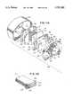
- FIG. 1is a generally perspective, exploded view of one form of the fluid flow indicator apparatus of the invention.
- FIG. 2is a cross-sectional view of the apparatus of FIG. 1 as it appears in an assembled state.
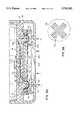
- FIG. 3is a front view of a pair of indicia bearing films of the apparatus which are adapted to be disposed in an overlaying configuration.
- FIG. 4is a generally diagrammatic front view showing the symbol that is viewable when the films are in their initial starting position.
- FIG. 5is a generally diagrammatic top view showing the pair of indicia bearing films of the apparatus in a shifted position indicating fluid flow through the device.
- FIG. 6is a generally diagrammatic front view showing the symbol that is viewable when the films are in the position shown in FIG. 5.
- FIG. 7is a generally diagrammatic top view showing the pair of indicia bearing films of the apparatus in shifted position indicating an absence of fluid flow through the outlet port of the device.
- FIG. 8is a generally diagrammatic frontview showing the symbol that is viewable when the films are in the position shown in FIG. 7.
- FIG. 9is a generally perspective top view of an alternate form of the apparatus of the invention showing the flow indicator embodied in a medical infusion device of the character used to infuse medicinal fluids into a patient.
- FIG. 10is a generally perspective, bottom view of the apparatus shown in FIG. 9.
- FIG. 11Ais a generally perspective, exploded view of the downstream portion of the apparatus of FIGS. 9 and 10 showing the flow indicator and a portion of the flow control means.
- FIG. 11Bis a generally perspective, exploded view of the remainder of the flow control means along with the reservoir subassembly portion of the apparatus shown in FIGS. 9 and 10.
- FIG. 11Cis a generally perspective, fragmentary view of a portion of the distendable membrane assembly of the apparatus.
- FIG. 12is a top plan view of the apparatus, partly broken away to show internal construction.
- FIG. 13is a cross-sectional view taken along lines 13--13 of FIG. 12.
- FIG. 14is a cross-sectional view taken along lines 14--14 of FIG. 13.
- FIG. 15is a cross-sectional view taken along lines 15--15 of FIG. 13.
- FIG. 16is a view of the apparatus taken along lines 16--16 of FIG. 13.
- FIG. 17is a cross-sectional view taken along lines 17--17 of FIG. 16.
- FIG. 18is a cross-sectional view taken along lines 18--18 of FIG. 16.
- FIG. 19is a cross-sectional view taken along lines 19--19 of FIG. 16.
- FIG. 20is a generally perspective, exploded view of the forward portion of the apparatus.
- FIG. 21is a front view of the apparatus.
- FIG. 21Ais a cross-sectional view taken along lines 21A--21A of FIG. 21.
- FIG. 22is a generally perspective view of the cover for the rate control apparatus of the invention.
- FIG. 23is a generally perspective, front view of the substrate portion of the rate control apparatus.
- FIG. 24is a generally perspective rear view of the substrate portion.
- FIG. 25is a generally perspective view of the output port of the apparatus.
- FIG. 26is a front view of the output port shown in FIG. 18.
- FIG. 27is a cross-sectional view taken along lines 27--27 of FIG. 26.
- FIG. 28is a bottom view of the luer valve fitting of the apparatus.
- FIG. 29is a cross-sectional view taken along lines 29--29 of FIG. 28.
- FIG. 30is an enlarged front view of the indicia carrying thin films of the apparatus of the invention.
- FIG. 31is a cross-sectional view similar to FIG. 21A showing the indicator means of the invention in its starting configuration.
- FIG. 32is a fragmentary front view showing the symbol that is viewable by the user when the apparatus is in the configuration shown in FIG. 31.
- FIG. 33is a cross-sectional view similar to FIG. 31, but showing the indicator means as it appears when fluid is flowing through the apparatus in a normal fashion.
- FIG. 34is a fragmentary front view showing the symbol that is viewable by the user when the apparatus is in the configuration shown in FIG. 33.
- FIG. 35is a cross-sectional view similar to FIG. 31, but showing the indicator means as it appears when there is a blockage downstream of the indicator means that prevents normal fluid flow.
- FIG. 36is a fragmentary front view showing the symbol that is viewable by the user when the apparatus is in the configuration shown in FIG. 35.
- one form of the fluid flow indicator means of the inventionis there shown in fluid communication with a main fluid supply line 14 that branches into first and second feeder lines or conduits 16 and 18 respectively.
- the indicator meanshere comprises an indicator base or platform 20 which is connected to a support or lens plate 22 having a viewing lens portion 22a.
- an outlet port assembly 25Connected to a substrate 24 is an outlet port assembly 25 which has a fluid outlet port 25b.
- first and second indicia-carrying meansDisposed between platform 20 and plate 22 are first and second indicia-carrying means shown here as thin films 26 and 28.
- Films 26 and 28which are in intimate contact, are preferably constructed from a substantially transparent, flexible material such as mylar.
- the indicia-carrying meanscan take various forms and can comprise any structure having a surface that will display a selected indicia.
- the downstream surface of the inferior or first film 26is printed with three integrated symbols "S", namely, a blue circle, a green arrow, and a red X, each consisting of diagonal stripes of color printed in an alternating pattern as, for example, blue, green, red, blue, green red, and so on (see also FIGS. 4, 6, and 8).
- the superior, or second film 28serves as a "mask” over the inferior film and is printed with a pattern of diagonal alternating clear and opaque stripes 28a that occur in a 1:2 ratio (FIG. 3).
- the printed ratio of the superior "mask”allows only one colored symbol to appear at a time when viewed through a viewing lens portion 22a provided in plate 22.
- each thin filmis able to move in opposing directions parallel to the film plane with its range of motion limited to one axis in the film plane by edge guides 38 provided on platform 30 (FIG. 1). As the films move, the visible symbol pattern viewed through viewing lens 22a changes due to the transverse displacement of the patterns imprinted on-the films (see FIGS. 4 through 8).
- support plate 22is provided with transversely spaced, channel-like depressions 40 and 42 which index with slots 34 and 36 respectively when the components are assembled in the manner shown in, FIG. 2.
- mechanical actuator meanshere provided as yieldably deformable mechanical actuators such as thin elastomeric elements 44 and 46. More particularly, first actuator element 44 aligns with slot 34 while the second actuator element 46 aligns with slot 36.
- the mechanical actuator elementsare deflected outwardly from their initial configuration whenever there is sufficient fluid pressure present within the feeder lines to cause their outward deflection as a result of fluid under pressure impinging on the actuator means via small apertures 50 and 52 provided in substrate 24. More particularly, during operation of the apparatus the first mechanical actuator element 44 is deflected by fluid pressure F-1 of fluid flowing through first conduit 16 and through aperture 50 provided in substrate 24. As depicted in FIGS. 5 and 33, as the first mechanical actuator means is deflected outwardly by fluid force F-1, the non-patterned portion 29 of indicator film 28 will be urged into expansion channel 40.
- the printed portion of the filmis transversely displaced a specific distance "D" (FIG. 5).
- Dthe specific distance
- This film displacementre-aligns the printed symbol patterns on the inferior film 26 with the mask pattern on the superior film 28 and results in a change of the symbol (in this case the arrow shown in FIG. 6) that is visible through the support plate viewing aperture 22a.
- both the first and second mechanical actuator elements 44 and 46are deflected outwardly toward their respective extension channels when feeder lines 16 and 18 are pressurized by fluid forces F-1 and F-2. While first elastomeric element 44 will be deflected by line pressure F-1, second elastomeric element 46 is constructed so that a greater pressure F-2 is required to cause its deflection. In the present embodiment of the invention, this occurs when fluid is not flowing through outlet port 25b thereby causing pressure buildup within a passageway 53 leading to aperture 52 (FIG. 2). When both mechanical actuators are deflected outwardly in the manner shown in FIG. 7, both the superior and inferior films are displaced transversely to a second position revealing a second symbol, as for example, an X as viewed through the viewing aperture of the support plate (see FIGS. 8 and 36).
- a third alignment of symbol patterns as indicated in FIGS. 3, 4, 31, and 32is visible when the device is in an unfilled state or when no fluid is flowing through conduits 16 and 18.
- the elementsthere is no fluid pressure exerted on either of the first and second mechanical actuator elements and, therefore, the elements remain in a non-deflected configuration.
- the inferior and superior filmsare not transversely displaced and thus exhibit a third combination of patterns resulting in a third symbol as, for example, a circle being visible through the viewing aperture of the support plate (FIGS. 4 and 32).
- the actuator elementscan be specially tailored to appropriately deflect under various pressure conditions thereby making the apparatus extremely versatile.
- FIGS. 9 through 36A particularly attractive use for the apparatus of the present invention is found in the medical field. More particularly, because of the simplicity, reliability and ease of use of the indicator devices of the invention, their use in combination with medical infusion devices provides an elegant means for providing a clearly interpreted visual display of the operating condition of the infusion device. Such a use is illustrated in FIGS. 9 through 36 wherein the indicator apparatus of the invention comprises one of the three major operating subsystems of a novel ambulatory medical infusion device 130 for delivering beneficial agents, such as medicaments to a patient.
- the apparatus there showncomprises three major cooperating subassembies namely, a reservoir subassembly, a flow rate control subassembly, and a flow indicator subassembly which embodies a form of indicator means somewhat similar to that shown in FIGS. 1 and 2.
- a reservoir subassemblynamely, a flow rate control subassembly, and a flow indicator subassembly which embodies a form of indicator means somewhat similar to that shown in FIGS. 1 and 2.
- this subassemblyincludes a base assembly 132, a stored energy source, or distendable membrane assembly 134, and a cover 136 for enclosing the stored energy source and the base assembly (see also FIGS. 13 and 14).
- the base assemblyincludes a ullage substrate 138 and a membrane capture housing 140 having a bottom opening 142 which receives the distendable membrane engaging element or protuberance 144.
- the ullage substrate 138comprises, in addition to the distendable member engaging protuberance or ullage 144, filling means which enables the fluid reservoir 146 formed between protuberance 144 and distended membrane 134 to be filled.
- This filling meanshere includes a fluid inlet 148 provided in a luer valve fitting 150, the character of which will presently be described.
- Filling 150is adapted to be interconnected with a filing conduit 149a (FIG. 9).
- Protuberance 144is provided with a longitudinally extending fluid passageway 152 (FIG. 11B) which communicates with fluid passageways 154 and 156 provided in the base portion 138a of ullage substrate 138 (see also FIGS. 13 and 14).
- Base portion 138a of ullage substrate 138includes an upstanding tongue 160 which extends about the perimeter of the base portion and is closely receivable within a groove 162 formed in the base of membrane capture housing 140 (FIGS. 11B and 13).
- housing 140is bonded to substrate 138 by any suitable means such as adhesive or sonic bonding.
- cover 136is mated With housing 140 in the manner shown in FIG. 13 and bonded in place.
- Cover 136is preferably constructed from a substantially transparent plastic material which is impermeable to fluids, including gases.
- Luer fitting 150includes a skirt portion 150a, a valve seat 150b and a biasing spring 150c which biases a ball check valve 168 toward seat 150b (see also FIG. 29). Ball 168 will lift from seat 150b against the urging of spring 150c during reservoir filling, but will sealably engage seat 150b after the reservoir has been filled.
- Inlet 148is closed by a closure cap 151 prior to and following the filling step.
- the stored energy meanscan be in the form of a single prestressed or unstressed isotropic, elastomeric distendable membrane, it is here shown as a laminate assemblage made up of a plurality of initially generally planar distendable elements or films.
- the stored energy meanscan be seen to comprise a laminate assemblage made up of individual layers 134, 134a, 134b, 134c, and 134d.
- Assemblage 134which is typically prestressed, cooperates with ullage substrate 138 to define a fluid chamber, or reservoir 146.
- the distendable membrane assemblage 134As previously discussed, as the distendable membrane assemblage 134 is distended by the fluid pressure exerted by the fluid flowing into inlet 148, internal stresses are formed therein which continuously urge the assemblage toward engagement with protuberance 144 as the assemblage tends to return toward its original configuration. As assemblage 134 moves toward protuberance 144, fluid within reservoir 146 will be uniformly and controllably forced outwardly through longitudinally extending passageway 152 in protuberance 144 and then into passageways 154 and 156 of portion 138a of ullage substrate 138.
- Various types of hard plastic materialsthat can be used to construct the base assembly and the cover.
- the membrane assemblagecan be constructed from a wide variety of elastomers and similar materials of a character well known in the art.
- this subsassemblyincludes novel flow control means which are disposed externally of reservoir 146 for controlling the rate of fluid flow of fluid from the device.
- the flow control meanscomprises a rate control membrane 66 (FIG. 11A) which is closely received within a circular recess 168 formed in support means shown here as a membrane support structure 170.
- the downstream wall 172 of recess 168is provided with fluid distribution means comprising a multiplicity of circumferentially spaced, arcuate-shaped, manifolding stand-off elements 174 against which membrane 166 is held in engagement by a disc-like member 176 (FIG.
- member 176is provided with fluid collection means shown here as a multiplicity of circumferentially spaced, manifolding stand-offs 178 which engage membrane 166 when member 176 is in position within cavity 168. More particularly, as indicated in FIG. 13, when member 176 is in place within cavity 168, the flow control membrane 166 is bonded at its circumference to member 170 and is securely positioned between stand-offs 174 and 178 which cooperate to define a multiplicity of concentric and radial extending fluid passageways, which function to direct fluid flow through the flow control means. Air within chamber 168 is vented via vent patch 192a and opening 192b (FIG. 11B).
- member 176includes a downwardly extending fluid inlet leg or segment 180 which is provided with a fluid passageway 182. Passageway 182 is adapted to communicate with chamber 168 when member 176 is mated with support structure 170. As shown in FIG. 23, support structure 170 has a centrally disposed recess 184 that receives inlet segment 180.
- wing-like protuberances 186are received within spaced-apart, arcuate-shaped cavities 188 formed in the base portion 138a of ullage substrate 138. Also formed in substrate 138 is a socket 190 (FIG. 13) which closely receives a tubular extension 192 formed as a part of inlet segment 180. Located proximate the upper edge of support structure 170 are spaced-apart capture grooves 196, which attach cover 136 to member 170.
- fluid inlet passageway 182 of member 176is placed in fluid communication with reservoir 146 via passageways 154 and 156.
- the fluidwill flow into passageway 154, next into passageway 156 then into passage 182 of member 76, and finally into chamber 168 formed in member 170.
- the fluid under pressureflows into the upstream portion of chamber 168 behind membrane 166, it will be distributed by standoffs 178 so that it will uniformly flow through membrane 166 and toward the fluid outlet port of the flow control subassembly. As best seen in FIGS.
- the outlet portcomprises an assembly 187 which is receivable in a cavity 173 formed in the back of downstream wall 170a of the substrate 170.
- Assembly 187includes a fluid outlet 190 and an internal chamber 192, the purpose of which will presently be described. During filling of chamber 192, air therewithin can be vented to atmosphere via vent patch 92a.
- the flow control means of this form of the inventionis shown as comprising a single layer of permeable material having the desired fluid flow characteristics.
- the flow control meanscan also comprise an assemblage of a plurality of layers of permeable materials, P-1, P-2, and P-3 of the character seen in FIG. 31 of U.S. Pat. No. 5,205,820 issued to the present inventors.
- These layerswhich may be composites, thin films, or porous substrates, may be constructed of any one of the materials described in U.S. Pat. No. 5,205,820 so that the fluid pressure flow characteristics of the assemblage can be precisely tailored for the particular medicinal or other fluid being dispensed.
- the flow indicator meanshere comprises an indicator base or platform 200, a support or lens plate 202, and a hollow housing 204 within which the platform and the support plate are mounted.
- plate 102has a viewing lens 202a which indexes with an aperture 204a provided in housing 204.
- first and second indicia-carrying meansDisposed between platform 200 and plate 202 are first and second indicia-carrying means shown here as thin films. These films, identified here as 206 and 208, are in intimate contact and are constructed from a substantially transparent, flexible material such as mylar.
- the indicia-carrying meanscan be any surface presenting member upon which indicia can be provided.
- the downstream surface of the inferior or first film 206is printed with three integrated symbols 207 (FIG. 30), namely, a blue circle 207a (FIG. 32), a green arrow 207b (FIG. 34), and a red X 207c (FIG.
- the superior, or second film 208serves as a "mask” over the inferior film 206 and is printed with a pattern of diagonal alternating clear and opaque strips 108a that occur in a 1:2 ratio.
- the printed ratio of the superior "mask”allows only one colored symbol to appear at a time when viewed through viewing lens 202a in plate 202.
- the inferior and superior filmsare provided at their opposite ends with apertures 210 which receive retention pins 212 provided on platform 200 (FIG.
- each thin filmis able to move in opposing directions parallel to the film plane with its range of motion limited to one axis in the film plane by edge guides 218 provided on platform 200 (FIG. 19). As the films move, the visible symbol pattern changes due to the transverse displacement of the patterns imprinted thereon.
- support plate 202is provided with transversely spaced, channel-like depressions 220 and 222 which index with slots. 214 and 216 respectively when the components are assembled in the manner shown in FIGS. 17 and 21.
- mechanical actuator meansAligned with the upstream (reservoir) side of slots 214 and 216 are mechanical actuator means here provided as mechanical actuators or elastomeric elements 224 and 226. More particularly the first actuator element 224 covers slot 214 and the second actuator element 226 covers slot 214.
- the mechanical actuator meansare deflected from their initial configuration whenever there is sufficient fluid pressure present within the fluid flow path to cause their outward deflection toward films 206 and 208.
- the first mechanical actuator element 224is deflected by fluid pressure of reservoir 146. More particularly, when there is sufficient fluid pressure in the fluid reservoir and fluid is being delivered by the stored energy means of the device, the first mechanical actuator means is deflected outwardly so as to urge the non-patterned portion 209 of indicator film 208 into expansion channel 222. As the film arches into channel 222, the printed portion of the film is transversely displaced a specific distance.
- This film displacementre-aligns the printed symbol patterns on the inferior film 206 with the mask pattern on the superior film 208 and results in a change of the symbol (in this case an arrow) see FIGS. 33 and 34 that is visible through the support plate viewing lens 202a.
- both the first and second mechanical actuator elements 224 and 226are deflected outwardly toward their respective extension channels when the device is filled and primed but not in a state of delivery or when there is a build up of fluid pressure during delivery that is caused by blockage of the delivery line downstream from second mechanical actuator element 226. While element 224 can be deflected by normal line pressure element 226 is deflected only by pressure caused by a downstream blockage. When both mechanical actuators are deflected outwardly, both the superior and inferior films are displaced transversely to a second position revealing a second symbol, as for example, an X as viewed through the viewing aperture of the support plate (see FIG. 36).
- a third alignment of symbol patterns as shown in FIG. 32is visible when the device is in an unfilled state or when the delivery line is open, the reservoir is empty and fluid delivery to the patient has been completed.
- the inferior and superior filmsare not transversely displaced and thus exhibit a third combination of patterns resulting in a third symbol as, for example, a circle being visible through the viewing aperture of the support plate (see FIGS. 31 and 32).
- the fluid to be dispensedis introduced into reservoir 146 via a fluid inlet conduit 149a (FIG. 9) which is connected to luer fitting 150. Fluid flowing into the fitting lifts check valve ball 168 against the urging of spring and causes the distendable membrane assembly to be displaced away from ullage protuberance 144 in the manner shown in FIG. 13. Air within housing 140 and cover 136 will be suitably vented to atmosphere via a vent 141 which is receivable within a vent aperture 141a provided in housing 140 (FIG. 11B). During the filling step, the gaseous component of the fluid is vented to atmosphere via a vent patch 143 provided in portion 138a of substrate 138 (FIGS. 11B and 13).
- the prestressed membrane assemblywill tend to return toward a less distended configuration causing fluid within the chamber to flow outwardly of passageway 152 and into passageways 154 and 156.
- the fluid under pressurewill next flow into passageway 182 of disc-shaped member 176.
- FIGS. 17 and 22it is to be observed that a portion of the fluid entering chamber 168 of member 170 from passageway 182 and upstream of membrane 166, can flow directly toward an ear-shaped extension 176a provided on member 176 via flow passageways 176b and 176c. From passageway 176c, the fluid will flow under pressure into passageway 170a formed in substrate 170 and toward passageway outlet 170b.
- Fluid flowing through outlet 170bwill impinge directly upon flow indicator element 224 which sealably engages a protuberance 171 formed on substrate 170 causing element 224 to deform outwardly in a manner to force portion 209 of indicator film 208 to arch into expansion channel 222. This, in turn, will cause transverse displacement of indicator film 208 in the manner previously described.
- Fluid flowing through passageway 182 of disc-shaped member 176will also be distributed over the upstream face of the rate control membrane 166 by the fluid distribution means, or protuberances 178 and will pass through the membrane at a predetermined controlled rate.
- the fluid flowing through the rate control membranewill be collected by the fluid collection means or protuberance 174 and then will flow via passageway 185 into passageway 192 of outlet port assembly 187.
- the fluidwill then flow outwardly of the device through fluid outlet 190 to which an infusion line 193 is connected (FIGS. 9, and 33). It is to be observed that a portion of the fluid flowing into outlet port assembly 187 is free to flow through passageway 192a provided in a protruding portion 187a thereof.
Landscapes
- Health & Medical Sciences (AREA)
- Physics & Mathematics (AREA)
- Hematology (AREA)
- Life Sciences & Earth Sciences (AREA)
- Engineering & Computer Science (AREA)
- Anesthesiology (AREA)
- Biomedical Technology (AREA)
- Heart & Thoracic Surgery (AREA)
- General Physics & Mathematics (AREA)
- Vascular Medicine (AREA)
- Animal Behavior & Ethology (AREA)
- General Health & Medical Sciences (AREA)
- Public Health (AREA)
- Veterinary Medicine (AREA)
- Fluid Mechanics (AREA)
- Infusion, Injection, And Reservoir Apparatuses (AREA)
Abstract
Description
Claims (27)
Priority Applications (7)
| Application Number | Priority Date | Filing Date | Title |
|---|---|---|---|
| US08/718,686US5721382A (en) | 1995-05-01 | 1996-09-24 | Apparatus for indicating fluid pressure within a conduit |
| US08/906,382US6010482A (en) | 1995-05-01 | 1997-08-05 | Apparatus for indicating fluid pressure in a conduit |
| US09/017,047US5962794A (en) | 1995-05-01 | 1998-02-02 | Fluid delivery apparatus with reservior fill assembly |
| US09/250,036US6086561A (en) | 1995-05-01 | 1999-02-12 | Fluid delivery apparatus with reservoir fill assembly |
| US09/363,288US6105442A (en) | 1995-05-01 | 1999-07-28 | Fluid delivery apparatus with reservoir fill assembly |
| US09/488,961US6293159B1 (en) | 1995-05-01 | 2000-01-21 | Fluid delivery apparatus with reservoir fill assembly |
| US09/562,740US6391006B1 (en) | 1995-05-01 | 2000-05-01 | Fluid delivery apparatus with reservoir fill assembly |
Applications Claiming Priority (2)
| Application Number | Priority Date | Filing Date | Title |
|---|---|---|---|
| US43222095A | 1995-05-01 | 1995-05-01 | |
| US08/718,686US5721382A (en) | 1995-05-01 | 1996-09-24 | Apparatus for indicating fluid pressure within a conduit |
Related Parent Applications (1)
| Application Number | Title | Priority Date | Filing Date |
|---|---|---|---|
| US43222095AContinuation-In-Part | 1995-05-01 | 1995-05-01 |
Related Child Applications (2)
| Application Number | Title | Priority Date | Filing Date |
|---|---|---|---|
| US08/906,382DivisionUS6010482A (en) | 1995-05-01 | 1997-08-05 | Apparatus for indicating fluid pressure in a conduit |
| US09/017,047Continuation-In-PartUS5962794A (en) | 1995-05-01 | 1998-02-02 | Fluid delivery apparatus with reservior fill assembly |
Publications (1)
| Publication Number | Publication Date |
|---|---|
| US5721382Atrue US5721382A (en) | 1998-02-24 |
Family
ID=27029404
Family Applications (2)
| Application Number | Title | Priority Date | Filing Date |
|---|---|---|---|
| US08/718,686Expired - Fee RelatedUS5721382A (en) | 1995-05-01 | 1996-09-24 | Apparatus for indicating fluid pressure within a conduit |
| US08/906,382Expired - Fee RelatedUS6010482A (en) | 1995-05-01 | 1997-08-05 | Apparatus for indicating fluid pressure in a conduit |
Family Applications After (1)
| Application Number | Title | Priority Date | Filing Date |
|---|---|---|---|
| US08/906,382Expired - Fee RelatedUS6010482A (en) | 1995-05-01 | 1997-08-05 | Apparatus for indicating fluid pressure in a conduit |
Country Status (1)
| Country | Link |
|---|---|
| US (2) | US5721382A (en) |
Cited By (43)
| Publication number | Priority date | Publication date | Assignee | Title |
|---|---|---|---|---|
| US6086560A (en)* | 1992-04-17 | 2000-07-11 | Science Incorporated | Fluid dispenser with fill adapter |
| WO2000047268A1 (en) | 1999-02-12 | 2000-08-17 | Science Incorporated | Fluid delivery apparatus with reservoir fill assembly |
| US6537250B1 (en) | 1997-08-27 | 2003-03-25 | Science, Incorporated | Fluid delivery device with electrically activated energy source |
| US20050033233A1 (en)* | 2003-08-04 | 2005-02-10 | Kriesel Marshall S. | Infusion apparatus with constant force spring energy source |
| US20050033232A1 (en)* | 2003-08-05 | 2005-02-10 | Kriesel Marshall S. | Infusion apparatus with modulated flow control |
| US20050263615A1 (en)* | 2004-05-26 | 2005-12-01 | Kriesel Marshall S | Fluid delivery apparatus with adjustable flow rate control |
| US20050277882A1 (en)* | 2004-05-26 | 2005-12-15 | Kriesel Marshall S | Infusion apparatus |
| US20050277884A1 (en)* | 2004-05-26 | 2005-12-15 | Kriesel Marshall S | Fluid delivery apparatus with bellows reservoir |
| US20050277883A1 (en)* | 2004-05-26 | 2005-12-15 | Kriesel Marshall S | Fluid delivery device |
| US20060149161A1 (en)* | 2004-12-29 | 2006-07-06 | Wilson Stephen F | System and method for measuring the pressure of a fluid system within a patient |
| US20060195057A1 (en)* | 2005-02-18 | 2006-08-31 | Kriesel Marshall S | Fluid delivery apparatus with vial fill |
| US20060199997A1 (en)* | 2005-02-24 | 2006-09-07 | Ethicon Endo-Surgery, Inc. | Monitoring of a food intake restriction device |
| US20060196552A1 (en)* | 2005-02-17 | 2006-09-07 | Kriesel Marshall S | Distal rate control device |
| US20060206052A1 (en)* | 2005-02-15 | 2006-09-14 | Kriesel Marshall S | Fluid delivery and mixing apparatus with flow rate control |
| US20060211912A1 (en)* | 2005-02-24 | 2006-09-21 | Dlugos Daniel F | External pressure-based gastric band adjustment system and method |
| US20060211914A1 (en)* | 2005-02-24 | 2006-09-21 | Hassler William L Jr | System and method for determining implanted device positioning and obtaining pressure data |
| US20060211913A1 (en)* | 2005-02-24 | 2006-09-21 | Dlugos Daniel F | Non-invasive pressure measurement in a fluid adjustable restrictive device |
| US7169128B2 (en) | 2003-08-04 | 2007-01-30 | Bioquiddity, Inc. | Multichannel fluid delivery device |
| US20070156090A1 (en)* | 2004-05-26 | 2007-07-05 | Kriesel Marshall S | Fluid delivery apparatus |
| US20070213837A1 (en)* | 2005-02-24 | 2007-09-13 | Ferreri Annie L | System and Method for Determining Implanted Device Orientation |
| US20070219501A1 (en)* | 2006-03-15 | 2007-09-20 | Kriesel Marshall S | Fluid dispensing apparatus |
| US20070235083A1 (en)* | 2005-02-24 | 2007-10-11 | Dlugos Daniel F | Apparatus for Adjustment and Sensing of Gastric Band Pressure |
| US20080009835A1 (en)* | 2005-02-17 | 2008-01-10 | Kriesel Marshall S | Fluid dispensing apparatus with flow rate control |
| US20080027376A1 (en)* | 2006-07-31 | 2008-01-31 | Kriesel Marshall S | Fluid dispensing device with additive |
| US20080160535A1 (en)* | 1997-12-15 | 2008-07-03 | Somalogic, Inc. | Methods and Reagents for Detecting Target Binding by Nucleic Acid Ligands |
| US20080243077A1 (en)* | 2007-04-02 | 2008-10-02 | Bivin Donald B | Fluid dispenser with uniformly collapsible reservoir |
| US20080250340A1 (en)* | 2006-04-06 | 2008-10-09 | Ethicon Endo-Surgery, Inc. | GUI for an Implantable Restriction Device and a Data Logger |
| US20080319385A1 (en)* | 2007-06-25 | 2008-12-25 | Kriesel Marshall S | Fluid dispenser with additive sub-system |
| US20090024083A1 (en)* | 2007-06-25 | 2009-01-22 | Kriesel Marshall S | Fluid dispenser with additive sub-system |
| US20090112103A1 (en)* | 2007-10-31 | 2009-04-30 | Codman & Shurtleff, Inc. | Wireless Pressure Sensing Shunts |
| US20090112308A1 (en)* | 2007-10-31 | 2009-04-30 | Codman Shurleff, Inc. | Wireless Shunts With Storage |
| US20090112147A1 (en)* | 2007-10-31 | 2009-04-30 | Codman Shurleff, Inc. | Wireless Pressure Setting Indicator |
| US20090107233A1 (en)* | 2007-10-31 | 2009-04-30 | Codman Shurleff, Inc. | Wireless Flow Sensor |
| US7828772B2 (en) | 2006-03-15 | 2010-11-09 | Bioquiddity, Inc. | Fluid dispensing device |
| US7927270B2 (en) | 2005-02-24 | 2011-04-19 | Ethicon Endo-Surgery, Inc. | External mechanical pressure sensor for gastric band pressure measurements |
| US20110186177A1 (en)* | 2007-12-31 | 2011-08-04 | Deka Products Limited Partnership | Apparatus, system and method for fluid delivery |
| US8057435B2 (en) | 2006-07-31 | 2011-11-15 | Kriesel Joshua W | Fluid dispenser |
| US20110306931A1 (en)* | 2006-02-09 | 2011-12-15 | Deka Products Limited Partnership | Pumping fluid delivery systems and methods using force application assembly |
| US8152710B2 (en) | 2006-04-06 | 2012-04-10 | Ethicon Endo-Surgery, Inc. | Physiological parameter analysis for an implantable restriction device and a data logger |
| US20130205909A1 (en)* | 2012-02-13 | 2013-08-15 | Autoland Scientech Co., Ltd. | Exterior pressure detection device for detecting fluid pressure in pipes |
| US9636070B2 (en) | 2013-03-14 | 2017-05-02 | DePuy Synthes Products, Inc. | Methods, systems, and devices for monitoring and displaying medical parameters for a patient |
| EP3534128A3 (en)* | 2009-08-13 | 2020-01-08 | Teleflex Life Sciences Unlimited Company | Pressure indicator |
| US10702174B2 (en) | 2007-06-27 | 2020-07-07 | Integra Lifesciences Corporation | Medical monitor user interface |
Families Citing this family (2)
| Publication number | Priority date | Publication date | Assignee | Title |
|---|---|---|---|---|
| US20030105428A1 (en)* | 2001-12-05 | 2003-06-05 | John Hogan | Electronically controlled fluid delivery device |
| MX2019001362A (en)* | 2016-08-24 | 2019-07-10 | Avent Inc | Flow indicator for an infusion pump. |
Citations (11)
| Publication number | Priority date | Publication date | Assignee | Title |
|---|---|---|---|---|
| US3675722A (en)* | 1971-04-05 | 1972-07-11 | Gen Fire Extinguisher Corp | Pressure indicator |
| US3703879A (en)* | 1971-04-06 | 1972-11-28 | Charles K Huthsing Jr | Pressure indicator |
| US3895631A (en)* | 1974-02-04 | 1975-07-22 | Alza Corp | Liquid infusion unit |
| US3939069A (en)* | 1971-12-06 | 1976-02-17 | Rhone-Poulenc-Textile | Artificial kidney and a method of ultrafiltering a liquid |
| US4020784A (en)* | 1975-10-24 | 1977-05-03 | Micro Pneumatic Logic, Inc. | Visual indicator for a fluid operated system |
| US4140117A (en)* | 1975-05-12 | 1979-02-20 | Alza Corporation | Cartridge for liquid infusion apparatus |
| US4343188A (en)* | 1980-08-27 | 1982-08-10 | Baker William E | Fluid pressure indicating apparatus |
| US4431425A (en)* | 1981-04-28 | 1984-02-14 | Quest Medical, Inc. | Flow fault sensing system |
| US4626243A (en)* | 1985-06-21 | 1986-12-02 | Applied Biomedical Corporation | Gravity-independent infusion system |
| US5039279A (en)* | 1990-03-15 | 1991-08-13 | Abbott Laboratories | Sensor for detecting fluid flow from a positive displacement pump |
| US5267980A (en)* | 1990-08-29 | 1993-12-07 | Random Corporation | Optical components for an I.V. flow detector |
Family Cites Families (1)
| Publication number | Priority date | Publication date | Assignee | Title |
|---|---|---|---|---|
| US5267900A (en)* | 1992-01-10 | 1993-12-07 | Clayton Terry W | Telephone message recording device and method |
- 1996
- 1996-09-24USUS08/718,686patent/US5721382A/ennot_activeExpired - Fee Related
- 1997
- 1997-08-05USUS08/906,382patent/US6010482A/ennot_activeExpired - Fee Related
Patent Citations (11)
| Publication number | Priority date | Publication date | Assignee | Title |
|---|---|---|---|---|
| US3675722A (en)* | 1971-04-05 | 1972-07-11 | Gen Fire Extinguisher Corp | Pressure indicator |
| US3703879A (en)* | 1971-04-06 | 1972-11-28 | Charles K Huthsing Jr | Pressure indicator |
| US3939069A (en)* | 1971-12-06 | 1976-02-17 | Rhone-Poulenc-Textile | Artificial kidney and a method of ultrafiltering a liquid |
| US3895631A (en)* | 1974-02-04 | 1975-07-22 | Alza Corp | Liquid infusion unit |
| US4140117A (en)* | 1975-05-12 | 1979-02-20 | Alza Corporation | Cartridge for liquid infusion apparatus |
| US4020784A (en)* | 1975-10-24 | 1977-05-03 | Micro Pneumatic Logic, Inc. | Visual indicator for a fluid operated system |
| US4343188A (en)* | 1980-08-27 | 1982-08-10 | Baker William E | Fluid pressure indicating apparatus |
| US4431425A (en)* | 1981-04-28 | 1984-02-14 | Quest Medical, Inc. | Flow fault sensing system |
| US4626243A (en)* | 1985-06-21 | 1986-12-02 | Applied Biomedical Corporation | Gravity-independent infusion system |
| US5039279A (en)* | 1990-03-15 | 1991-08-13 | Abbott Laboratories | Sensor for detecting fluid flow from a positive displacement pump |
| US5267980A (en)* | 1990-08-29 | 1993-12-07 | Random Corporation | Optical components for an I.V. flow detector |
Cited By (80)
| Publication number | Priority date | Publication date | Assignee | Title |
|---|---|---|---|---|
| US6086560A (en)* | 1992-04-17 | 2000-07-11 | Science Incorporated | Fluid dispenser with fill adapter |
| US6537250B1 (en) | 1997-08-27 | 2003-03-25 | Science, Incorporated | Fluid delivery device with electrically activated energy source |
| US20080160535A1 (en)* | 1997-12-15 | 2008-07-03 | Somalogic, Inc. | Methods and Reagents for Detecting Target Binding by Nucleic Acid Ligands |
| WO2000047268A1 (en) | 1999-02-12 | 2000-08-17 | Science Incorporated | Fluid delivery apparatus with reservoir fill assembly |
| US20080051701A1 (en)* | 2003-08-04 | 2008-02-28 | Kriesel Marshall S | Infusion apparatus with constant force spring energy source |
| US20050033233A1 (en)* | 2003-08-04 | 2005-02-10 | Kriesel Marshall S. | Infusion apparatus with constant force spring energy source |
| US7789853B2 (en) | 2003-08-04 | 2010-09-07 | Bioquiddity, Inc. | Infusion apparatus with constant force spring energy source |
| US7220244B2 (en) | 2003-08-04 | 2007-05-22 | Bioquiddity, Inc. | Infusion apparatus with constant force spring energy source |
| US7169128B2 (en) | 2003-08-04 | 2007-01-30 | Bioquiddity, Inc. | Multichannel fluid delivery device |
| US20050033232A1 (en)* | 2003-08-05 | 2005-02-10 | Kriesel Marshall S. | Infusion apparatus with modulated flow control |
| US20050277883A1 (en)* | 2004-05-26 | 2005-12-15 | Kriesel Marshall S | Fluid delivery device |
| US20050277884A1 (en)* | 2004-05-26 | 2005-12-15 | Kriesel Marshall S | Fluid delivery apparatus with bellows reservoir |
| US20070156090A1 (en)* | 2004-05-26 | 2007-07-05 | Kriesel Marshall S | Fluid delivery apparatus |
| US7220245B2 (en) | 2004-05-26 | 2007-05-22 | Kriesel Marshall S | Infusion apparatus |
| US7470253B2 (en) | 2004-05-26 | 2008-12-30 | Bioquiddity, Inc. | Fluid delivery apparatus with adjustable flow rate control |
| US20050277882A1 (en)* | 2004-05-26 | 2005-12-15 | Kriesel Marshall S | Infusion apparatus |
| US20050263615A1 (en)* | 2004-05-26 | 2005-12-01 | Kriesel Marshall S | Fluid delivery apparatus with adjustable flow rate control |
| US9220424B2 (en) | 2004-12-29 | 2015-12-29 | DePuy Synthes Products, Inc. | System and method for measuring the pressure of a fluid system within a patient |
| US9931043B2 (en) | 2004-12-29 | 2018-04-03 | Integra Lifesciences Switzerland Sàrl | System and method for measuring the pressure of a fluid system within a patient |
| US20090270759A1 (en)* | 2004-12-29 | 2009-10-29 | Codman & Shurtleff, Inc. | System and Method for Measuring the Pressure of a Fluid System Within a Patient |
| US7585280B2 (en) | 2004-12-29 | 2009-09-08 | Codman & Shurtleff, Inc. | System and method for measuring the pressure of a fluid system within a patient |
| US20060149161A1 (en)* | 2004-12-29 | 2006-07-06 | Wilson Stephen F | System and method for measuring the pressure of a fluid system within a patient |
| US20060206052A1 (en)* | 2005-02-15 | 2006-09-14 | Kriesel Marshall S | Fluid delivery and mixing apparatus with flow rate control |
| US20060196552A1 (en)* | 2005-02-17 | 2006-09-07 | Kriesel Marshall S | Distal rate control device |
| US7694938B2 (en) | 2005-02-17 | 2010-04-13 | Bioquiddity, Inc. | Distal rate control device |
| US20080009835A1 (en)* | 2005-02-17 | 2008-01-10 | Kriesel Marshall S | Fluid dispensing apparatus with flow rate control |
| US7837653B2 (en) | 2005-02-18 | 2010-11-23 | Bioquiddity, Inc. | Fluid delivery apparatus with vial fill |
| US20060195057A1 (en)* | 2005-02-18 | 2006-08-31 | Kriesel Marshall S | Fluid delivery apparatus with vial fill |
| US7658196B2 (en) | 2005-02-24 | 2010-02-09 | Ethicon Endo-Surgery, Inc. | System and method for determining implanted device orientation |
| US20070235083A1 (en)* | 2005-02-24 | 2007-10-11 | Dlugos Daniel F | Apparatus for Adjustment and Sensing of Gastric Band Pressure |
| US20060199997A1 (en)* | 2005-02-24 | 2006-09-07 | Ethicon Endo-Surgery, Inc. | Monitoring of a food intake restriction device |
| US20060211912A1 (en)* | 2005-02-24 | 2006-09-21 | Dlugos Daniel F | External pressure-based gastric band adjustment system and method |
| US7775966B2 (en) | 2005-02-24 | 2010-08-17 | Ethicon Endo-Surgery, Inc. | Non-invasive pressure measurement in a fluid adjustable restrictive device |
| US8066629B2 (en) | 2005-02-24 | 2011-11-29 | Ethicon Endo-Surgery, Inc. | Apparatus for adjustment and sensing of gastric band pressure |
| US8016745B2 (en) | 2005-02-24 | 2011-09-13 | Ethicon Endo-Surgery, Inc. | Monitoring of a food intake restriction device |
| US8016744B2 (en) | 2005-02-24 | 2011-09-13 | Ethicon Endo-Surgery, Inc. | External pressure-based gastric band adjustment system and method |
| US7927270B2 (en) | 2005-02-24 | 2011-04-19 | Ethicon Endo-Surgery, Inc. | External mechanical pressure sensor for gastric band pressure measurements |
| US20060211914A1 (en)* | 2005-02-24 | 2006-09-21 | Hassler William L Jr | System and method for determining implanted device positioning and obtaining pressure data |
| US7775215B2 (en) | 2005-02-24 | 2010-08-17 | Ethicon Endo-Surgery, Inc. | System and method for determining implanted device positioning and obtaining pressure data |
| US20060211913A1 (en)* | 2005-02-24 | 2006-09-21 | Dlugos Daniel F | Non-invasive pressure measurement in a fluid adjustable restrictive device |
| US20070213837A1 (en)* | 2005-02-24 | 2007-09-13 | Ferreri Annie L | System and Method for Determining Implanted Device Orientation |
| US20110306931A1 (en)* | 2006-02-09 | 2011-12-15 | Deka Products Limited Partnership | Pumping fluid delivery systems and methods using force application assembly |
| US20110282284A1 (en)* | 2006-03-15 | 2011-11-17 | Kriesel Marshall S | Fluid dispensing apparatus |
| US20110092904A1 (en)* | 2006-03-15 | 2011-04-21 | Kriesel Marshall S | Fluid dispensing device |
| US7828772B2 (en) | 2006-03-15 | 2010-11-09 | Bioquiddity, Inc. | Fluid dispensing device |
| US20070219501A1 (en)* | 2006-03-15 | 2007-09-20 | Kriesel Marshall S | Fluid dispensing apparatus |
| US8672885B2 (en)* | 2006-03-15 | 2014-03-18 | Marshall S. Kriesel | Fluid dispensing device |
| US7993304B2 (en) | 2006-03-15 | 2011-08-09 | Bioquiddity, Inc. | Fluid dispensing apparatus |
| US8870742B2 (en) | 2006-04-06 | 2014-10-28 | Ethicon Endo-Surgery, Inc. | GUI for an implantable restriction device and a data logger |
| US20080250340A1 (en)* | 2006-04-06 | 2008-10-09 | Ethicon Endo-Surgery, Inc. | GUI for an Implantable Restriction Device and a Data Logger |
| US8152710B2 (en) | 2006-04-06 | 2012-04-10 | Ethicon Endo-Surgery, Inc. | Physiological parameter analysis for an implantable restriction device and a data logger |
| US8292848B2 (en) | 2006-07-31 | 2012-10-23 | Bio Quiddity, Inc. | Fluid dispensing device with additive |
| US8057435B2 (en) | 2006-07-31 | 2011-11-15 | Kriesel Joshua W | Fluid dispenser |
| US20080027376A1 (en)* | 2006-07-31 | 2008-01-31 | Kriesel Marshall S | Fluid dispensing device with additive |
| US20080243077A1 (en)* | 2007-04-02 | 2008-10-02 | Bivin Donald B | Fluid dispenser with uniformly collapsible reservoir |
| US20080319385A1 (en)* | 2007-06-25 | 2008-12-25 | Kriesel Marshall S | Fluid dispenser with additive sub-system |
| US20090024083A1 (en)* | 2007-06-25 | 2009-01-22 | Kriesel Marshall S | Fluid dispenser with additive sub-system |
| US8211059B2 (en) | 2007-06-25 | 2012-07-03 | Kriesel Marshall S | Fluid dispenser with additive sub-system |
| US10702174B2 (en) | 2007-06-27 | 2020-07-07 | Integra Lifesciences Corporation | Medical monitor user interface |
| US8480612B2 (en) | 2007-10-31 | 2013-07-09 | DePuy Synthes Products, LLC | Wireless shunts with storage |
| US20090112147A1 (en)* | 2007-10-31 | 2009-04-30 | Codman Shurleff, Inc. | Wireless Pressure Setting Indicator |
| US20090112103A1 (en)* | 2007-10-31 | 2009-04-30 | Codman & Shurtleff, Inc. | Wireless Pressure Sensing Shunts |
| US8454524B2 (en) | 2007-10-31 | 2013-06-04 | DePuy Synthes Products, LLC | Wireless flow sensor |
| US8579847B2 (en) | 2007-10-31 | 2013-11-12 | Codman & Shurtleff, Inc. | Wireless pressure setting indicator |
| US20090112308A1 (en)* | 2007-10-31 | 2009-04-30 | Codman Shurleff, Inc. | Wireless Shunts With Storage |
| US10265509B2 (en) | 2007-10-31 | 2019-04-23 | Integra LifeSciences Switzerland Sarl | Wireless shunts with storage |
| US8864666B2 (en) | 2007-10-31 | 2014-10-21 | DePuy Synthes Products, LLC | Wireless flow sensor |
| US8870768B2 (en) | 2007-10-31 | 2014-10-28 | DePuy Synthes Products, LLC | Wireless flow sensor methods |
| US7842004B2 (en) | 2007-10-31 | 2010-11-30 | Codman & Shurtleff, Inc. | Wireless pressure setting indicator |
| US20090107233A1 (en)* | 2007-10-31 | 2009-04-30 | Codman Shurleff, Inc. | Wireless Flow Sensor |
| US9204812B2 (en) | 2007-10-31 | 2015-12-08 | DePuy Synthes Products, LLC | Wireless pressure sensing shunts |
| US20110186177A1 (en)* | 2007-12-31 | 2011-08-04 | Deka Products Limited Partnership | Apparatus, system and method for fluid delivery |
| US11642283B2 (en) | 2007-12-31 | 2023-05-09 | Deka Products Limited Partnership | Method for fluid delivery |
| US8881774B2 (en)* | 2007-12-31 | 2014-11-11 | Deka Research & Development Corp. | Apparatus, system and method for fluid delivery |
| US11701300B2 (en) | 2007-12-31 | 2023-07-18 | Deka Products Limited Partnership | Method for fluid delivery |
| US12121497B2 (en) | 2007-12-31 | 2024-10-22 | Deka Products Limited Partnership | Method for fluid delivery |
| EP3534128A3 (en)* | 2009-08-13 | 2020-01-08 | Teleflex Life Sciences Unlimited Company | Pressure indicator |
| US8844373B2 (en)* | 2012-02-13 | 2014-09-30 | Chung-Yi HUANG | Exterior pressure detection device for detecting fluid pressure in pipes |
| US20130205909A1 (en)* | 2012-02-13 | 2013-08-15 | Autoland Scientech Co., Ltd. | Exterior pressure detection device for detecting fluid pressure in pipes |
| US9636070B2 (en) | 2013-03-14 | 2017-05-02 | DePuy Synthes Products, Inc. | Methods, systems, and devices for monitoring and displaying medical parameters for a patient |
Also Published As
| Publication number | Publication date |
|---|---|
| US6010482A (en) | 2000-01-04 |
Similar Documents
| Publication | Publication Date | Title |
|---|---|---|
| US5721382A (en) | Apparatus for indicating fluid pressure within a conduit | |
| US6394980B2 (en) | Fluid delivery apparatus with flow indicator and vial fill | |
| US6086561A (en) | Fluid delivery apparatus with reservoir fill assembly | |
| US5649910A (en) | Fluid delivery apparatus and method of making same | |
| US5840071A (en) | Fluid delivery apparatus with flow indicator and vial fill | |
| US6183441B1 (en) | Variable rate infusion apparatus with indicator and adjustable rate control | |
| US6645175B2 (en) | Variable rate infusion apparatus with indicator and adjustable rate control | |
| US5962794A (en) | Fluid delivery apparatus with reservior fill assembly | |
| US6090071A (en) | Fluid dispenser with fill adapter | |
| US5980489A (en) | Fluid dispenser with fill adapter | |
| US6355019B1 (en) | Variable rate infusion apparatus with indicator and adjustable rate control | |
| US6293159B1 (en) | Fluid delivery apparatus with reservoir fill assembly | |
| US6537249B2 (en) | Multiple canopy | |
| WO2012160495A2 (en) | Infusion apparatus with flow detector | |
| US6231545B1 (en) | Variable rate infusion apparatus with indicator and adjustable rate control | |
| EP0824674B1 (en) | Fluid flow indicating apparatus | |
| US20010039397A1 (en) | Fluid delivery apparatus with flow indicator and vial fill | |
| AU722783B2 (en) | Fluid delivery apparatus and method of making same | |
| WO1998026834A1 (en) | Fluid delivery apparatus | |
| CA2219884A1 (en) | Fluid delivery apparatus and method of making same |
Legal Events
| Date | Code | Title | Description |
|---|---|---|---|
| AS | Assignment | Owner name:SCIENCE INCORPORATED, MINNESOTA Free format text:ASSIGNMENT OF ASSIGNORS INTEREST;ASSIGNORS:KRIESEL, MARSHALL S.;GARRISON, JAMES M.;ARNOLD, STEVEN;AND OTHERS;REEL/FRAME:008771/0444 Effective date:19971008 | |
| AS | Assignment | Owner name:SCIENCE INCORPORATED, MINNESOTA Free format text:ASSIGNMENT OF ASSIGNORS INTEREST;ASSIGNORS:KRIESEL, MARSHALL S.;GARRISON, JAMES M.;ARNOLD, STEVEN;AND OTHERS;REEL/FRAME:009146/0065;SIGNING DATES FROM 19980331 TO 19980403 | |
| FEPP | Fee payment procedure | Free format text:PAT HLDR NO LONGER CLAIMS SMALL ENT STAT AS SMALL BUSINESS (ORIGINAL EVENT CODE: LSM2); ENTITY STATUS OF PATENT OWNER: SMALL ENTITY Free format text:PAT HOLDER CLAIMS SMALL ENTITY STATUS - SMALL BUSINESS (ORIGINAL EVENT CODE: SM02); ENTITY STATUS OF PATENT OWNER: SMALL ENTITY | |
| AS | Assignment | Owner name:WALLIN R. WALLIN D/B/A WALLIN FAMILY FOUNDATION, M Free format text:SECURITY INTEREST;ASSIGNOR:SCIENCE INCORPORATED;REEL/FRAME:011958/0404 Effective date:20001106 Owner name:WILLIAM F. FARLEY D/B/A LIVINGSTON CAPITAL, MINNES Free format text:SECURITY INTEREST;ASSIGNOR:SCIENCE INCORPORATED;REEL/FRAME:011958/0404 Effective date:20001106 Owner name:HODDER, WILLIAM A., MINNESOTA Free format text:SECURITY INTEREST;ASSIGNOR:SCIENCE INCORPORATED;REEL/FRAME:011958/0404 Effective date:20001106 Owner name:BRATTAIN, DONALD, MINNESOTA Free format text:SECURITY INTEREST;ASSIGNOR:SCIENCE INCORPORATED;REEL/FRAME:011958/0404 Effective date:20001106 Owner name:BEDNARCZYK, W. WILLIAM, MINNESOTA Free format text:SECURITY INTEREST;ASSIGNOR:SCIENCE INCORPORATED;REEL/FRAME:011958/0404 Effective date:20001106 Owner name:SIT INVESTMENT ASSOCIATES, INC., BY EUGENE C. SIT, Free format text:SECURITY INTEREST;ASSIGNOR:SCIENCE INCORPORATED;REEL/FRAME:011958/0404 Effective date:20001106 Owner name:DAVID E. KELBY AND VIRGINIA H. KELBY, AS JOINT TEN Free format text:SECURITY INTEREST;ASSIGNOR:SCIENCE INCORPORATED;REEL/FRAME:011958/0404 Effective date:20001106 Owner name:OKABENA PARTNERSHIP V-8 BY OKABENA INVESTMENT SERV Free format text:SECURITY INTEREST;ASSIGNOR:SCIENCE INCORPORATED;REEL/FRAME:011958/0404 Effective date:20001106 Owner name:GROSSMAN INVESTMENTS D/B/A N. BUD GROSSMAN, MANAGI Free format text:SECURITY INTEREST;ASSIGNOR:SCIENCE INCORPORATED;REEL/FRAME:011958/0404 Effective date:20001106 | |
| FPAY | Fee payment | Year of fee payment:4 | |
| REMI | Maintenance fee reminder mailed | ||
| LAPS | Lapse for failure to pay maintenance fees | ||
| STCH | Information on status: patent discontinuation | Free format text:PATENT EXPIRED DUE TO NONPAYMENT OF MAINTENANCE FEES UNDER 37 CFR 1.362 | |
| FP | Lapsed due to failure to pay maintenance fee | Effective date:20060224 | |
| AS | Assignment | Owner name:SCIENCE INCORPORATED, MINNESOTA Free format text:RELEASE OF SECURITY AGREEMENT;ASSIGNORS:OKABENA PARTNERSIP V-8 BY OKABENA INVESTMENT SERVICES, INC. MANAGER;WINSTON R. WALLIN/WALLIN FAMILY FOUNDATION;WILLIAM F. FARLEY D/B/A LIVINGSTON CAPITAL;AND OTHERS;REEL/FRAME:019704/0733 Effective date:20070628 Owner name:PESCADERO BEACH HOLDINGS CORPORATION, CALIFORNIA Free format text:ASSIGNMENT OF ASSIGNORS INTEREST;ASSIGNOR:SCIENCO INCORPORATED;REEL/FRAME:019733/0235 Effective date:20070710 | |
| AS | Assignment | Owner name:PESCADERO BEACH HOLDINGS CORPORATION, CALIFORNIA Free format text:ASSIGNMENT OF ASSIGNORS INTEREST;ASSIGNOR:SCIENCE INCORPORATED;REEL/FRAME:019733/0298 Effective date:20070710 |