US5721373A - Pneumatic fusion joint test system and method - Google Patents
Pneumatic fusion joint test system and methodDownload PDFInfo
- Publication number
- US5721373A US5721373AUS08/640,281US64028196AUS5721373AUS 5721373 AUS5721373 AUS 5721373AUS 64028196 AUS64028196 AUS 64028196AUS 5721373 AUS5721373 AUS 5721373A
- Authority
- US
- United States
- Prior art keywords
- fusion joint
- pressure
- saddle
- test system
- seal
- Prior art date
- Legal status (The legal status is an assumption and is not a legal conclusion. Google has not performed a legal analysis and makes no representation as to the accuracy of the status listed.)
- Expired - Lifetime
Links
Images


Classifications
- G—PHYSICS
- G01—MEASURING; TESTING
- G01M—TESTING STATIC OR DYNAMIC BALANCE OF MACHINES OR STRUCTURES; TESTING OF STRUCTURES OR APPARATUS, NOT OTHERWISE PROVIDED FOR
- G01M3/00—Investigating fluid-tightness of structures
- G01M3/02—Investigating fluid-tightness of structures by using fluid or vacuum
- G01M3/26—Investigating fluid-tightness of structures by using fluid or vacuum by measuring rate of loss or gain of fluid, e.g. by pressure-responsive devices, by flow detectors
- G01M3/28—Investigating fluid-tightness of structures by using fluid or vacuum by measuring rate of loss or gain of fluid, e.g. by pressure-responsive devices, by flow detectors for pipes, cables or tubes; for pipe joints or seals; for valves ; for welds
- G01M3/2853—Investigating fluid-tightness of structures by using fluid or vacuum by measuring rate of loss or gain of fluid, e.g. by pressure-responsive devices, by flow detectors for pipes, cables or tubes; for pipe joints or seals; for valves ; for welds for pipe joints or seals
Definitions
- This inventionrelates generally to methods and apparatus for testing pipe joints, and more particularly, to methods and apparatus for testing, using fluid pressure, saddle fusion joints prepared on site when tapping into existing plastic pipe gas distribution pipelines.
- plastic pipe gas distribution pipelinessuch as polyethylene (PE) pipelines
- PEpolyethylene
- the T-connectorhas a saddle portion which is fused to an outer surface of the pipe forming a saddle fusion joint.
- An elongated threaded opening in the T-connectorhouses a threaded cutter that taps a hole in the pipe and serves as a shut off valve after the pipe is tapped.
- a service line outletis provided in the side of the elongated threaded portion for releasing gas from the pipeline when the cutter is unthreaded.
- the threaded cutterincludes a threaded upper portion which cooperates with the internal threads of the threaded opening, and a lower portion with a sharp, thin, metal annulus which acts as the curing edge. After the saddle portion is fused to the main pipeline, the cutter screws into the pipe surface so that the sharp edge cuts through the pipe wall. The cutter is then partially unscrewed and may be used as a valve to control gas flow.
- one object of this inventionis to provide methods and apparatus for automatically testing pipe fusion joints that includes using a fluid pressure based testing system for testing the integrity of pipe fusion joints.
- Another objectis to provide methods and apparatus for testing fusion joints in pipes before the pipe is cut wherein unnecessary damage to the surface of the pipe is substantially avoided and the test system adapts to differing sized T-connectors.
- Another objectis to provide methods and apparatus for controllably testing fusion joints in pipes to detect relatively small leaks in the joint.
- a further object of the inventionis to provide methods and apparatus for automatically testing fusion joints in pipes having a computer based control system to facilitate detection of relatively small leaks from the fusion joint by accounting for pressure changes caused by visco-elastic properties of the test system to obtain accurate testing results.
- an electronic fusion joint test systemfor automatically testing a saddle interface, or fusion joint, with a pipe having a mechanism for controllably pressurizing a substantially isolated area about the fusion joint to a set pressure using a fluid pressure source.
- a pressure sensorsenses a change in pressure about the fusion joint after pressurization and a computer electronically determines whether the fusion joint is within an acceptable integrity range.
- an adjustable sealing mechanismcouples to the internal bore of the saddle connector to effectively seal an isolated area about the fusion joint.
- the sealing mechanismhas passages therein to allow pressurization of the isolated area.
- the pressure sensoris located in the passage to sense the pressure in the isolated area.
- a valve in the passageprevents sourced fluid pressure from escaping the isolated area.
- a digital processing devicesuch as a portable computing device compares an actual sensed pressure, obtained from the sensor, to a desired control pressure value to determine whether a leak exists.
- the sealing mechanismincludes a movable tapered neoprene seal with an internal passage for pressurizing the isolated area.
- the neoprene sealis compressible and has visco-elastic properties.
- the computeraccounts for the visco-elastic properties of the seal prior to determining a change in pressure by waiting a predetermined time before obtaining the pressure value after initial pressurization.
- the movable sealis fixed to a housing that slidably engages with a frame.
- the housingalso includes a fluid passage for receiving the pressure transducer, the fluid under pressure and a valve for regulating fluid in the passage.
- the movable sealis preferably affixed to the housing so that its passage is in fluid communication with the fluid passage in the housing.
- the sealmay be a universal type seal such as a seal having a tapered outer surface to seal variable sized internal bores of differing sized saddle T-connectors.
- the preferred frame containing the movable seal and housing with the pressure transducer and the valveis horizontally placed around an outer surface of the saddle T-connector.
- the frameis secured to the saddle connector through the tightening of the movable seal into the internal bore of the saddle. Tightening of the seal may occur using a threaded rod with a handle coupled to the housing.
- a capis placed over any other openings in the saddle connector to isolate the area inside the saddle T-connector.
- pressure from a pressure sourcesuch as an air compressor
- the computermeasures the sourced fluid pressure using the pressure transducer and audibly and visually notifies the operator when a desired initial pressure has been reached.
- the operatorthen adjusts the valve to seal the isolated area.
- the computerwaits for a predetermined period of time to account for viscoelastic related pressure changes to settle and reads the actual pressure in the isolated area. After a second predetermined period of time, the computer takes another pressure reading of the actual pressure and compares the two actual readings to determine the amount of change of pressure over a predetermined time. If the determination indicates that the change is improper, the computer notifies the operator of the poor integrity of the fusion joint.
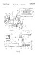
- FIG. 1is a perspective view of an embodiment of the invention attached to a saddle T-connector
- FIG. 2is a side view of an embodiment of a sealing mechanism coupled to a saddle T-connector
- FIG. 3is a partial top view and partial cross sectional end view of a saddle T-connector sealing mechanic including a pressure sensor and valve in accordance with one aspect of the invention
- FIG. 4is cross sectional view of a universal seal in accordance with one embodiment of the invention.
- FIG. 5is a partial end view of the sealing mechanism of FIG. 3 with a potion of a cover removed showing a valve and pressure sensor;
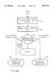
- FIGS. 6a-6bshow a block diagram generally depicting one embodiment of a method for testing pipe fusion joints in accordance with the invention.
- test systemdetects a pressure drop in an isolated volume within the fused saddle connector after pressurizing the volume with compressed air or other fluid.
- a frame sealing assemblyseals the volume and a computer is used to assist in pressurizing and monitoring the pressure in the isolated volume.
- a detected pressure dropwill indicate a leak at the fusion interface and therefore identify a faulty fusion joint.
- a pipe 10has an outer surface 12.
- a conventional saddle T-connector 14is heat fused to the outer surface 12 around the outer periphery of a saddle portion 16 (partially shown).
- An internal threaded bore 18 for receiving a pipe cutter,extends from the saddle portion 16 away from the pipe 10.
- a service line tap 20having an internal fluid passage or bore in communication with the threaded bore 18 forms a "T" configuration.
- the inventive saddle testing system 22includes a sealing mechanism, such as a metal frame sealing assembly 24 that houses a valve and pressure sensing arrangement 26 along with a universal T-connector seal 28.
- the valve and pressure sensing arrangement 26fluidly connects to the universal seal 28 through fluid passages.
- a cap 32such as a manufacturer provided cap, is used to screwably attach to the threaded bore 18 where the cutter resides to seal the bore opening.
- the metal frame sealing assembly 24is designed to horizontally clamp to an outer surface of the saddle T-connector 14.
- the metal frame assembly 24has a base 31 and a flattened tip 33 at an opposing end forming a frame 34.
- the base 31includes a threaded opening 36 for receiving a threaded adjustment rod 38.
- the adjustment rod 38has a handle 40 for adjusting the universal seal.
- An aluminum block housing 42contains the valve and pressure transducer arrangement 26.
- the housing 42is slidably adjustable along the frame 34 in an axial direction.
- the universal seal 28such as a tapered neoprene seal, is fixedly attached to a side of the housing 42 opposite a side receiving the adjusting rod 38.
- the universal seal 28has an internal seal passage 46 (FIG. 4) extending axially there through.
- the seal passage 46is in fluid communication with a housing fluid passage 48 (FIG. 3) for receiving fluid from a pressure source, such as an air compressor.
- a pressure sourcesuch as an air compressor.
- the internal seal passage 46is in fluid communication with the housing fluid passage 48.
- a tube end 49 of the fluid passage 48includes a conventional male type ribbed end (not shown) for receiving a standard air chuck to facilitate connection to the fluid source.
- passages 46 and 48are such that they form a continuous passage and the only openings in the frame sealing assembly 24 are through the end 49 of passage 48 and an end of the universal seal 28.
- the passage 48may be formed by drilling holes into the sides of the housing 42 and plugging the holes to seal the ends thereof. It will be recognized that tubing or other suitable material for defining fluid passages may also be used instead of an aluminum block.
- the housing 42contains the fluid passage 48 and, a valve 52.
- the valve 52is disposed in the passage 48 and includes a knob 54 for adjusting the degree of openness of the valve.
- the valve 52adjusts to completely seal the passage 48 to prevent fluid pressure from escaping.
- the housing fluid passage 48is preferably bored into a lower section of the aluminum block housing 42.
- the housing 42also contains differential pressure transducer 58.
- the pressure transducer 58may be an Omega PX 101-100G5V type transducer or any other suitable transducer that outputs a 1V-5V signal in response to pressure changes.
- the pressure transducer 58is held in the housing 42 by a transducer bracket 60 or by any other suitable attachment.
- Transducer bracket 60connects to an inner wall of the housing 42.
- Pressure transducer 58has a tip 62 which is inserted into passage 48 and is thereby in fluid communication with passages 46 and 48.
- the passage 48is extended through the use of common tube connectors (male and female connectors shown in FIG. 5) as known in the art, to allow the pressure transducer 58 to be in fluid communication with the passage 48.
- the pressure transducer 58senses the pressure changes that occur within these passages and includes an electrical connector 59 to provide electrical data signals to a microprocessor portion of the controller 30.
- the data signalsrepresent the measured pressure in the passage 48 and
- the movable universal seal 28preferably has a fruste-conical configuration or tapered outer surface 60 to seal variable sized internal bores.
- the universal seal 28is formed by a plastic inner ribbed core 62 with at least a portion thereof surrounded by a compressible outer tapered cover 64, such as neoprene or similar material.
- the inner ribbed corehas a series of circumferentially disposed ribs 66a-66b.
- the ribs 66a-66bvary in circumference by being smaller at a tip of the universal seal 28 and larger at a base thereof.
- the compressible outer tapered cover 64has an internal surface for matingly engaging with the ribs.
- the universal seal 28is slidably moveable along the frame 34 axis by virtue of the adjustment rod 38 and rotating handle 40.
- clockwise rotation of handle 40will move the universal seal 28 toward the internal bore of the saddle T-connector 14 and toward the flattened tip 32 of the frame.
- Counter clockwise rotation of handle 40will move the universal seal 28 in an opposite direction.
- the housing 42may be notched to have shoulders on either side that ride along a top edge of the frame 34.
- the frame assembly 24also includes rubber pads 68 attached along an inside face of flattened tip 33. The rubber pads will contact an outer surface of the saddle T-connector 14 when the universal seal 28 is tightly engaged in the service tap internal bore.
- the rubber pads 68may be screwed or glued to the frame and prevent frictional damage to the outer surface of the T-connector 14.
- the tapered universal seal 28frictionally engages with an internal bore opening of the service line tap 20 to prevent the ambient air from entering the inner isolated area of the saddle tee during testing.
- the cap 32sealing the main bore 18, the valve 52 sealing an end of passage 48 and the tapered universal seal 28 sealing the service line bore, the inside volume of the saddle T-connector 14 is substantially isolated.
- the metal frame assembly 24is shown connected to the service line tap 20, the assembly 24 can be suitably designed to be connected to the bore opening and a cap may be used to seal the service tap opening.
- the pressure transducer 58 and valve 52can measure and supply pressurized air in either opening.
- a transducer and/or valve/transducer combinationcan be located in a cutter opening 18, or the transducer and valve can be in separated openings. However, it is preferable that the transducer and valve be located in the service opening.
- the service tap bore openingis sealed with the frame sealing assembly by horizontally orientating the frame 34 and turning the knob 40 to plug the service tap opening with the universal seal 28.
- the operatorthen attaches a source of compressed air, such as an air hose, to the end 49 of the passage 48.
- the valve 52should preferably be open.
- the controller 30may be housed in a plastic or metal console (not shown) with a keyboard, push buttons and LCD display. Given the rugged environment in which the system must be used, the keypads are preferably built inside a lid and the LCD display and push buttons are preferably water/splash resistant.
- the controller 30may be a suitably programmed computer, or other digital processing device, which includes a microcomputer, such as a Motorola 68HC11 microcomputer with associated memory, control circuitry, input circuitry and an interface (RS-232 or the like) to facilitate the operation as further described below.
- the isolated areais pressurized to a predetermined level.
- the controller 30controls the LCD display in the console to display a message asking the operator if testing should begin. If the operator does not activate a start button on the console, the system will continue to prompt the operator to begin testing. As shown in block 74, if the operator activates the start button, the test system, via the controller 30, requests the operator to input the desired initial fluid pressure to which the isolated area is to be pressurized.
- the operatorenters a desired initial test pressure value (P test1 ), preferably 100 psi, through a touchpad or keyboard in the console. This value is stored in memory for later comparison.
- P test1a desired initial test pressure value
- the controller 30senses the amount of fluid pressure in the isolated area by monitoring signals from the pressure transducer 58.
- the electronic signals from the pressure transducer 58are read by a 16 bit A/D input on a microprocessor portion of the controller 30 as indicated by block 78. This allows for a relatively high resolution reading.
- the actual sensed test value (P test2 )is compared to the stored initial pressure value (P test1 ) entered by the operator.
- This automatic pressure sensingcontinues for a predetermined time period, such as 60 seconds or until the desired pressure of 100 psi is reached, as illustrated in block 80.
- the predetermined time periodis programmed into memory of the controller 30.
- An internal timeris used to determine the amount of elapsed time. If the internal timer times out before the desired pressure is reached, the system continues to sense the pressure.
- the controllerdetermines that the desired test pressure is reached, the operator is notified via the LCD display and audible alarm that the test pressure has been reached, as seen in block 82.
- the operatorcloses the valve 52 to prevent fluid pressure from escaping through the end 49.
- the fluid pressure sourcecan be disconnected at this point if desired.
- the controlleraccounts for pressure changes caused by visco-elastic changes in the universal seal 28 and plastic saddle T connector 14 to remove the variation from the analysis. It has been found that pressure drops in the isolated area can occur due to the expansion or contraction of the universal seal 28 and plastic T-connector when fluid pressure is initially applied. To compensate for the change in pressure, the controller 30 waits a predetermined period of time, such as 10 seconds before storing an initial pressure reading value (Pi) from the pressure transducer.
- a predetermined period of timesuch as 10 seconds before storing an initial pressure reading value (Pi) from the pressure transducer.
- the controller 30then stores the initial pressure reading value (Pi) for later comparison.
- the controller 30continues to monitor the pressure in the isolated area for a predetermined period of time, such as two minutes, as seen in block 90.
- the monitored pressureis continually displayed on the LCD for visual review by the operator.
- the predetermined time periodis adjustable by entering a desired time into the controller 30.
- the controller 30stores samples of actual pressure readings to determine the rate of pressure change, if any.
- a suitable criterion for measuring the pressure dropis if the pressure drops less than 10 inches of water in two minutes for the fusion joint to be pronounced acceptable. This value was chosen to eliminate pressure changes arising from the minute deformation of the neoprene seal 28. The visco-elastic deformation occurs because of the applied pressure and temperature changes of the compressed air.
- the controllerobtains and stores a final pressure reading value (Pf) as indicated in block 92.
- the controller 30compares the final pressure reading value (Pf) with the initial pressure reading value (Pi) to determine the integrity of the fusion joint.
- the range of pressure change and rate of change of pressure changesdetermines the integrity of the tested fusion joint. These ranges are stored in the controller. For example, if (Pi-Pf) is within a suitable range, such as between 0 psi and 0.41 psi, the fusion joint integrity is considered acceptable and the controller will visually display "GOOD JOINT" as shown in block 96. If (Pi-Pf) is far enough outside the acceptable range, such as greater than 0.55 psi, the controller 30 will display "BAD JOINT" as shown in block 98. Finally, as indicated by block 100, if the pressure difference is outside the acceptable range but within the unacceptable range, such as between 0.42 psi and 0.55 psi, the controller 30 will display "RETEST" and prompt the operator to retest the fusion joint.
- compressed fluidsuch as air at about 100 psi
- a fluid sourcethrough the passage 48 until a desired pressure is reached, thereby pressurizing a substantially isolated area about the fusion joint to a set pressure.
- the microprocessorsenses a change in pressure about the fusion joint.
- the pressure in the saddle cavityis monitored by the controller for a predetermined period of time.
- the controllerdetermines, based on the sensed change in pressure, whether the fusion joint is within an acceptable integrity range. If the pressure decreases by more than a set amount indicating a leak, the saddle joint is deemed to be faulty. If on the other hand, the pressure does not decrease or decreases by less than a set amount, the saddle joint is deemed to be satisfactory.
- the advantages of this inventionare now apparent.
- the heat fused jointmay be tested before the pipe is cut.
- the pipeis not damaged during the testing process and mechanical test plugs are eliminated.
- the above described automated interactive fluid pressure test systemdetects small fusion joint test leaks and takes into account visco-elastic effects of the sealing mechanism.
Landscapes
- Physics & Mathematics (AREA)
- General Physics & Mathematics (AREA)
- Examining Or Testing Airtightness (AREA)
Abstract
Description
Claims (13)
Priority Applications (1)
| Application Number | Priority Date | Filing Date | Title |
|---|---|---|---|
| US08/640,281US5721373A (en) | 1996-04-30 | 1996-04-30 | Pneumatic fusion joint test system and method |
Applications Claiming Priority (1)
| Application Number | Priority Date | Filing Date | Title |
|---|---|---|---|
| US08/640,281US5721373A (en) | 1996-04-30 | 1996-04-30 | Pneumatic fusion joint test system and method |
Publications (1)
| Publication Number | Publication Date |
|---|---|
| US5721373Atrue US5721373A (en) | 1998-02-24 |
Family
ID=24567608
Family Applications (1)
| Application Number | Title | Priority Date | Filing Date |
|---|---|---|---|
| US08/640,281Expired - LifetimeUS5721373A (en) | 1996-04-30 | 1996-04-30 | Pneumatic fusion joint test system and method |
Country Status (1)
| Country | Link |
|---|---|
| US (1) | US5721373A (en) |
Cited By (3)
| Publication number | Priority date | Publication date | Assignee | Title |
|---|---|---|---|---|
| US20040118454A1 (en)* | 2002-11-25 | 2004-06-24 | Alcatel | Method of fitting a cable into a pipe |
| US20050050749A1 (en)* | 2003-09-09 | 2005-03-10 | David Hauch | Forced air circulation for centrifugal pellet dryer |
| CN102829935A (en)* | 2012-08-21 | 2012-12-19 | 芜湖通和汽车管路系统有限公司 | Oil-cooled tube bulb leakage detection fixture and detection method thereof |
Citations (36)
| Publication number | Priority date | Publication date | Assignee | Title |
|---|---|---|---|---|
| US2462575A (en)* | 1944-12-27 | 1949-02-22 | Uel T Walker | Pipe coupling |
| US2572613A (en)* | 1945-11-27 | 1951-10-23 | Bell Telephone Labor Inc | Setscrew |
| US2682796A (en)* | 1949-09-23 | 1954-07-06 | Snap On Tools Corp | Predetermined torque release and torque indicating wrench |
| GB770611A (en)* | 1955-06-24 | 1957-03-20 | M H H Engineering Company Ltd | Improvements in wrenches having torque recording means thereon |
| US3213673A (en)* | 1962-02-13 | 1965-10-26 | Sr Saul Schulhoff | Sealing pads for use in can testing machines |
| US3444732A (en)* | 1967-06-06 | 1969-05-20 | Albert L Robbins | Method and apparatus for determining optimum bonding parameters for thermoplastic material |
| US3479072A (en)* | 1966-06-20 | 1969-11-18 | John Kosar | Positive locking,nonmarring set screw |
| US3501993A (en)* | 1968-12-17 | 1970-03-24 | Henry F Swenson | Setscrew with rotatable plastic end |
| US3826646A (en)* | 1969-10-13 | 1974-07-30 | G Karlsson | Method for treating melts and means for carrying out this treatment |
| US3952691A (en)* | 1975-01-06 | 1976-04-27 | Gte Sylvania Incorporated | Fluid pressure sensor device |
| US3978881A (en)* | 1975-06-05 | 1976-09-07 | The Westward Company | Gas line pierce valve |
| US4025371A (en)* | 1975-03-08 | 1977-05-24 | Bielomatik Leuze & Co. | Welding containers |
| US4040289A (en)* | 1972-11-08 | 1977-08-09 | Clark Joseph H | Method and arrangement for air testing of sewer lateral connections |
| US4078833A (en)* | 1976-09-30 | 1978-03-14 | Hershey Products Inc. | Testable pipe saddle |
| DE2829009A1 (en)* | 1978-07-01 | 1980-01-10 | Werkzeug Union Gmbh | TORQUE WRENCH |
| SU755544A1 (en)* | 1977-11-28 | 1980-08-15 | Vni Instrument Inst | Dynamometric wrench |
| US4352708A (en)* | 1980-09-08 | 1982-10-05 | Mcelroy Arthur H | Defined force fusion machine for joining plastic pipe |
| US4467636A (en)* | 1981-08-11 | 1984-08-28 | Josef Dagn | Testing instrument for pipes or other cavities to be tested as to tightness |
| DE3318910A1 (en)* | 1983-05-25 | 1984-11-29 | Oskar Ing.(grad.) 7073 Lorch Mohilo | Method and device for programming an electronic wrench |
| US4513605A (en)* | 1982-01-20 | 1985-04-30 | Manfred Hawerkamp | Method and device for testing welds of thermoplastic parts |
| US4533424A (en)* | 1984-01-13 | 1985-08-06 | Mcelroy Manufacturing, Inc. | Pipe fusion apparatus with load cell for attaching side wall fittings |
| US4657626A (en)* | 1982-12-06 | 1987-04-14 | Illinois Tool Works Inc. | Friction welding tool |
| US4664001A (en)* | 1985-11-25 | 1987-05-12 | Deuer Manufacturing Inc. | Torque wrench with audio and visual indicator |
| US4712809A (en)* | 1983-04-18 | 1987-12-15 | Societe Anonyme Styled Legris | Method and device for assembling several components, particularly connection fittings for fluid couplings |
| US4715214A (en)* | 1986-10-03 | 1987-12-29 | S. Himmelstein And Company | Leak tester |
| US4759225A (en)* | 1987-06-01 | 1988-07-26 | Ryeson Corporation | Torque tool and torque tool analyzer |
| US4791839A (en)* | 1986-05-30 | 1988-12-20 | Raymond Engineering Inc. | Apparatus and method for determining torque and presenting digital torque readout in a torque wrench system |
| US4809735A (en)* | 1986-11-19 | 1989-03-07 | Perfection Corporation | Valve and tapping tee apparatus and method |
| US4822203A (en)* | 1986-04-02 | 1989-04-18 | Robert Emmett | Clamps and connectors |
| US4899684A (en)* | 1987-08-17 | 1990-02-13 | Jednotne Rolnicke Druzstvo Jedlova Vo Vysnej Jedlovej | Pressure indicating bottle stopper |
| US4940259A (en)* | 1989-03-13 | 1990-07-10 | Standard International, Inc. | Swivel lug pipe joint connections |
| US4949744A (en)* | 1986-12-04 | 1990-08-21 | Kai Heed | Method and device for mounting a body in a conduit containing fluid |
| US4951697A (en)* | 1989-11-27 | 1990-08-28 | Bs&B Safety Systems, Inc. | Rupture disk failure indicating apparatus |
| US4958541A (en)* | 1989-10-13 | 1990-09-25 | Snap-On Tools Corporation | Electronic torque wrench with tactile indication |
| US5172616A (en)* | 1990-10-13 | 1992-12-22 | Teac Corporation | Torque wrench |
| US5394775A (en)* | 1994-02-10 | 1995-03-07 | Fagerstrom; Jon E. | Musical drum precision tuning tool |
- 1996
- 1996-04-30USUS08/640,281patent/US5721373A/ennot_activeExpired - Lifetime
Patent Citations (36)
| Publication number | Priority date | Publication date | Assignee | Title |
|---|---|---|---|---|
| US2462575A (en)* | 1944-12-27 | 1949-02-22 | Uel T Walker | Pipe coupling |
| US2572613A (en)* | 1945-11-27 | 1951-10-23 | Bell Telephone Labor Inc | Setscrew |
| US2682796A (en)* | 1949-09-23 | 1954-07-06 | Snap On Tools Corp | Predetermined torque release and torque indicating wrench |
| GB770611A (en)* | 1955-06-24 | 1957-03-20 | M H H Engineering Company Ltd | Improvements in wrenches having torque recording means thereon |
| US3213673A (en)* | 1962-02-13 | 1965-10-26 | Sr Saul Schulhoff | Sealing pads for use in can testing machines |
| US3479072A (en)* | 1966-06-20 | 1969-11-18 | John Kosar | Positive locking,nonmarring set screw |
| US3444732A (en)* | 1967-06-06 | 1969-05-20 | Albert L Robbins | Method and apparatus for determining optimum bonding parameters for thermoplastic material |
| US3501993A (en)* | 1968-12-17 | 1970-03-24 | Henry F Swenson | Setscrew with rotatable plastic end |
| US3826646A (en)* | 1969-10-13 | 1974-07-30 | G Karlsson | Method for treating melts and means for carrying out this treatment |
| US4040289A (en)* | 1972-11-08 | 1977-08-09 | Clark Joseph H | Method and arrangement for air testing of sewer lateral connections |
| US3952691A (en)* | 1975-01-06 | 1976-04-27 | Gte Sylvania Incorporated | Fluid pressure sensor device |
| US4025371A (en)* | 1975-03-08 | 1977-05-24 | Bielomatik Leuze & Co. | Welding containers |
| US3978881A (en)* | 1975-06-05 | 1976-09-07 | The Westward Company | Gas line pierce valve |
| US4078833A (en)* | 1976-09-30 | 1978-03-14 | Hershey Products Inc. | Testable pipe saddle |
| SU755544A1 (en)* | 1977-11-28 | 1980-08-15 | Vni Instrument Inst | Dynamometric wrench |
| DE2829009A1 (en)* | 1978-07-01 | 1980-01-10 | Werkzeug Union Gmbh | TORQUE WRENCH |
| US4352708A (en)* | 1980-09-08 | 1982-10-05 | Mcelroy Arthur H | Defined force fusion machine for joining plastic pipe |
| US4467636A (en)* | 1981-08-11 | 1984-08-28 | Josef Dagn | Testing instrument for pipes or other cavities to be tested as to tightness |
| US4513605A (en)* | 1982-01-20 | 1985-04-30 | Manfred Hawerkamp | Method and device for testing welds of thermoplastic parts |
| US4657626A (en)* | 1982-12-06 | 1987-04-14 | Illinois Tool Works Inc. | Friction welding tool |
| US4712809A (en)* | 1983-04-18 | 1987-12-15 | Societe Anonyme Styled Legris | Method and device for assembling several components, particularly connection fittings for fluid couplings |
| DE3318910A1 (en)* | 1983-05-25 | 1984-11-29 | Oskar Ing.(grad.) 7073 Lorch Mohilo | Method and device for programming an electronic wrench |
| US4533424A (en)* | 1984-01-13 | 1985-08-06 | Mcelroy Manufacturing, Inc. | Pipe fusion apparatus with load cell for attaching side wall fittings |
| US4664001A (en)* | 1985-11-25 | 1987-05-12 | Deuer Manufacturing Inc. | Torque wrench with audio and visual indicator |
| US4822203A (en)* | 1986-04-02 | 1989-04-18 | Robert Emmett | Clamps and connectors |
| US4791839A (en)* | 1986-05-30 | 1988-12-20 | Raymond Engineering Inc. | Apparatus and method for determining torque and presenting digital torque readout in a torque wrench system |
| US4715214A (en)* | 1986-10-03 | 1987-12-29 | S. Himmelstein And Company | Leak tester |
| US4809735A (en)* | 1986-11-19 | 1989-03-07 | Perfection Corporation | Valve and tapping tee apparatus and method |
| US4949744A (en)* | 1986-12-04 | 1990-08-21 | Kai Heed | Method and device for mounting a body in a conduit containing fluid |
| US4759225A (en)* | 1987-06-01 | 1988-07-26 | Ryeson Corporation | Torque tool and torque tool analyzer |
| US4899684A (en)* | 1987-08-17 | 1990-02-13 | Jednotne Rolnicke Druzstvo Jedlova Vo Vysnej Jedlovej | Pressure indicating bottle stopper |
| US4940259A (en)* | 1989-03-13 | 1990-07-10 | Standard International, Inc. | Swivel lug pipe joint connections |
| US4958541A (en)* | 1989-10-13 | 1990-09-25 | Snap-On Tools Corporation | Electronic torque wrench with tactile indication |
| US4951697A (en)* | 1989-11-27 | 1990-08-28 | Bs&B Safety Systems, Inc. | Rupture disk failure indicating apparatus |
| US5172616A (en)* | 1990-10-13 | 1992-12-22 | Teac Corporation | Torque wrench |
| US5394775A (en)* | 1994-02-10 | 1995-03-07 | Fagerstrom; Jon E. | Musical drum precision tuning tool |
Cited By (4)
| Publication number | Priority date | Publication date | Assignee | Title |
|---|---|---|---|---|
| US20040118454A1 (en)* | 2002-11-25 | 2004-06-24 | Alcatel | Method of fitting a cable into a pipe |
| US6976498B2 (en) | 2002-11-25 | 2005-12-20 | Alcatel | Method of fitting a cable into a pipe |
| US20050050749A1 (en)* | 2003-09-09 | 2005-03-10 | David Hauch | Forced air circulation for centrifugal pellet dryer |
| CN102829935A (en)* | 2012-08-21 | 2012-12-19 | 芜湖通和汽车管路系统有限公司 | Oil-cooled tube bulb leakage detection fixture and detection method thereof |
Similar Documents
| Publication | Publication Date | Title |
|---|---|---|
| EP0756700B1 (en) | Method and apparatus for testing oilfield tubular threaded connections | |
| US5483838A (en) | Fluid flow connector and gauge assembly | |
| US5072621A (en) | Pipeline leak detector apparatus and method | |
| US20050109082A1 (en) | Method for testing parts for leaks | |
| US6209562B1 (en) | Valve assembly, pressure testing apparatus and testing method for propane tank system | |
| US7581433B2 (en) | Cylinder leak detector | |
| US5992438A (en) | Pressure testing assembly and testing method for propane tank systems | |
| KR100293116B1 (en) | Method and apparatus for testing a fluid conduit system for leaks | |
| US5721373A (en) | Pneumatic fusion joint test system and method | |
| US5304757A (en) | Combination differential and static pressure switch | |
| US6199432B1 (en) | Fluid pressure testing | |
| US5679904A (en) | Method and test plug for field testing pipe joints | |
| US6223766B1 (en) | Pressure testing apparatus and testing method for propane tank systems | |
| US6209560B1 (en) | Pressure testing assembly and testing method for propane tank systems | |
| US5787916A (en) | Pressure testing assembly for propane tank systems and testing method | |
| CA2224224A1 (en) | Method and apparatus for testing threaded joints and threaded members | |
| CN208968724U (en) | Low-temperature breakaway valve experimental rig | |
| JP4757691B2 (en) | Pipe leak inspection method | |
| JPH08285720A (en) | Leak test method for underground service piping system | |
| CN1967201A (en) | Apparatus and method for inspecting quality of molded foam parts | |
| CA2299145C (en) | Pressure testing apparatus and testing method for propane tank systems | |
| CN113109032A (en) | Measurement experiment method for transient whipping behavior of pressurized pipeline | |
| JPH0886713A (en) | Piping leakage detecting device | |
| JP2576917B2 (en) | Gas leak detection device | |
| CN223412918U (en) | Gas pipe joint sealing detection device |
Legal Events
| Date | Code | Title | Description |
|---|---|---|---|
| AS | Assignment | Owner name:GAS RESEARCH INSTITUTE, ILLINOIS Free format text:ASSIGNMENT OF ASSIGNORS INTEREST;ASSIGNOR:BATTELLE;REEL/FRAME:008608/0407 Effective date:19960708 Owner name:BATTELLE, OHIO Free format text:ASSIGNMENT OF ASSIGNORS INTEREST;ASSIGNORS:STETS, JOSEPH A.;PIMPUTKAR, SUDHEER M.;REEL/FRAME:008608/0320 Effective date:19960702 | |
| STCF | Information on status: patent grant | Free format text:PATENTED CASE | |
| FEPP | Fee payment procedure | Free format text:PAYOR NUMBER ASSIGNED (ORIGINAL EVENT CODE: ASPN); ENTITY STATUS OF PATENT OWNER: SMALL ENTITY Free format text:PAYER NUMBER DE-ASSIGNED (ORIGINAL EVENT CODE: RMPN); ENTITY STATUS OF PATENT OWNER: SMALL ENTITY | |
| FPAY | Fee payment | Year of fee payment:4 | |
| FPAY | Fee payment | Year of fee payment:8 | |
| AS | Assignment | Owner name:GAS TECHNOLOGY INSTITUTE, ILLINOIS Free format text:ASSIGNMENT OF ASSIGNORS INTEREST;ASSIGNOR:GAS RESEARCH INSTITUTE;REEL/FRAME:017448/0282 Effective date:20060105 | |
| FPAY | Fee payment | Year of fee payment:12 |