US5720907A - Method for manufacturing an optical connector assembly - Google Patents
Method for manufacturing an optical connector assemblyDownload PDFInfo
- Publication number
- US5720907A US5720907AUS08/428,804US42880495AUS5720907AUS 5720907 AUS5720907 AUS 5720907AUS 42880495 AUS42880495 AUS 42880495AUS 5720907 AUS5720907 AUS 5720907A
- Authority
- US
- United States
- Prior art keywords
- ferrule
- mold
- base member
- thermoplastic material
- cylindrical
- Prior art date
- Legal status (The legal status is an assumption and is not a legal conclusion. Google has not performed a legal analysis and makes no representation as to the accuracy of the status listed.)
- Expired - Fee Related
Links
Images


Classifications
- G—PHYSICS
- G02—OPTICS
- G02B—OPTICAL ELEMENTS, SYSTEMS OR APPARATUS
- G02B6/00—Light guides; Structural details of arrangements comprising light guides and other optical elements, e.g. couplings
- G02B6/24—Coupling light guides
- G02B6/36—Mechanical coupling means
- G02B6/38—Mechanical coupling means having fibre to fibre mating means
- G02B6/3807—Dismountable connectors, i.e. comprising plugs
- G02B6/3833—Details of mounting fibres in ferrules; Assembly methods; Manufacture
- G02B6/3834—Means for centering or aligning the light guide within the ferrule
- G02B6/3835—Means for centering or aligning the light guide within the ferrule using discs, bushings or the like
- G02B6/3837—Means for centering or aligning the light guide within the ferrule using discs, bushings or the like forwarding or threading methods of light guides into apertures of ferrule centering means
- G—PHYSICS
- G02—OPTICS
- G02B—OPTICAL ELEMENTS, SYSTEMS OR APPARATUS
- G02B6/00—Light guides; Structural details of arrangements comprising light guides and other optical elements, e.g. couplings
- G02B6/24—Coupling light guides
- G02B6/36—Mechanical coupling means
- G02B6/38—Mechanical coupling means having fibre to fibre mating means
- G02B6/3807—Dismountable connectors, i.e. comprising plugs
- G02B6/3833—Details of mounting fibres in ferrules; Assembly methods; Manufacture
- G02B6/3865—Details of mounting fibres in ferrules; Assembly methods; Manufacture fabricated by using moulding techniques
- G—PHYSICS
- G02—OPTICS
- G02B—OPTICAL ELEMENTS, SYSTEMS OR APPARATUS
- G02B6/00—Light guides; Structural details of arrangements comprising light guides and other optical elements, e.g. couplings
- G02B6/24—Coupling light guides
- G02B6/36—Mechanical coupling means
- G02B6/38—Mechanical coupling means having fibre to fibre mating means
- G02B6/3807—Dismountable connectors, i.e. comprising plugs
- G02B6/3869—Mounting ferrules to connector body, i.e. plugs
- G—PHYSICS
- G02—OPTICS
- G02B—OPTICAL ELEMENTS, SYSTEMS OR APPARATUS
- G02B6/00—Light guides; Structural details of arrangements comprising light guides and other optical elements, e.g. couplings
- G02B6/24—Coupling light guides
- G02B6/36—Mechanical coupling means
- G02B6/38—Mechanical coupling means having fibre to fibre mating means
- G02B6/3807—Dismountable connectors, i.e. comprising plugs
- G02B6/381—Dismountable connectors, i.e. comprising plugs of the ferrule type, e.g. fibre ends embedded in ferrules, connecting a pair of fibres
- G02B6/3818—Dismountable connectors, i.e. comprising plugs of the ferrule type, e.g. fibre ends embedded in ferrules, connecting a pair of fibres of a low-reflection-loss type
- G02B6/3821—Dismountable connectors, i.e. comprising plugs of the ferrule type, e.g. fibre ends embedded in ferrules, connecting a pair of fibres of a low-reflection-loss type with axial spring biasing or loading means
- G—PHYSICS
- G02—OPTICS
- G02B—OPTICAL ELEMENTS, SYSTEMS OR APPARATUS
- G02B6/00—Light guides; Structural details of arrangements comprising light guides and other optical elements, e.g. couplings
- G02B6/24—Coupling light guides
- G02B6/36—Mechanical coupling means
- G02B6/38—Mechanical coupling means having fibre to fibre mating means
- G02B6/3807—Dismountable connectors, i.e. comprising plugs
- G02B6/3887—Anchoring optical cables to connector housings, e.g. strain relief features
- G02B6/38875—Protection from bending or twisting
- G—PHYSICS
- G02—OPTICS
- G02B—OPTICAL ELEMENTS, SYSTEMS OR APPARATUS
- G02B6/00—Light guides; Structural details of arrangements comprising light guides and other optical elements, e.g. couplings
- G02B6/24—Coupling light guides
- G02B6/36—Mechanical coupling means
- G02B6/38—Mechanical coupling means having fibre to fibre mating means
- G02B6/3807—Dismountable connectors, i.e. comprising plugs
- G02B6/389—Dismountable connectors, i.e. comprising plugs characterised by the method of fastening connecting plugs and sockets, e.g. screw- or nut-lock, snap-in, bayonet type
- G02B6/3893—Push-pull type, e.g. snap-in, push-on
Definitions
- This inventionrelates to optical connectors, and more particularly to a method and apparatus for manufacturing a connector subassembly comprising a cylindrical ferrule and a base member.
- Optical fiber connectorsare an essential part of substantially any optical fiber communication system.
- such connectorsmay be used to join segments of fiber into longer lengths; to connect fiber to active devices such as radiation sources, detectors and repeaters; or to connect fiber to passive devices such as switches and attenuators.
- optical fiber connectorAnother function of the optical fiber connector is to provide mechanical stability and protection to the junction in its working environment. Achieving low insertion loss in coupling two fibers is generally a function of the alignment of the fiber ends, the width of the gap between the ends, and the optical surface condition of either or both ends. Stability and junction protection is generally a function of connector design (e.g., minimization of the different thermal expansion and mechanical movement effects).
- An optical fiber connectortypically includes a small cylinder with a glass or plastic fiber installed along its central axis.
- the connector plugcomprises a cylindrical ferrule, a base member which holds the ferrule, a compression spring, and a cap that surrounds the ferrule and spring.
- the connector plugcomprises a cylindrical ferrule, a base member which holds the ferrule, a compression spring, and a cap that surrounds the ferrule and spring.
- the cylindrical ferruleneeds to be of high precision and is typically made from a ceramic material.
- the cylindrical ferruleis held rigidly in the base member by an adhesive.
- the ferrule and the base membereach include an opening that extends lengthwise from one end to the other.
- these openingswill be referred to as a "passageway" when discussing the ferrule, and a “bore” when discussing the base member.
- the central axis of the passageway and the boreneed to be axially aligned--particularly in the region where the ferrule meets the base member so that an optical fiber can be threaded along their common axis. And while manufacturing tolerances may approach "zero,” practical considerations such as cost have dictated that axial alignment tolerance be relaxed while still assuring that an optical fiber can pass through the junction where the bore of the base member abuts the passageway of the ferrule.
- a fiber entry conein the proximal end of the ferrule where the fiber is inserted.
- a funnelcan be produced in a variety of different ways such as by grinding, etching, or fire polishing.
- thisis a process that consumes time and resources and ultimately leads to a product having a higher final cost.
- An optical connector assemblyincludes a plastic base member which is overmolded onto a cylindrical ferrule having an axial passageway which extends from one end of the ferrule to the other.
- the moldcomprises a distribution channel for routing plastic material into a base cavity which includes a first slot for holding the cylindrical ferrule, and a second slot for supporting a movable core.
- An end portion of the ferruleextends into the base cavity.
- An end portion of the core pinincludes a conical tip which also extends into the base cavity and engages the axial passageway of the ferrule.
- the first and second slotsare generally cylindrical and coaxially aligned.
- pressurized and heated polycarbonate plasticis used.
- the core pinis spring loaded to limit the amount of pressure applied to the ferrule.
- a brakeis applied to the core pin so that it remains within the axial passageway of the ferrule when the pressurized thermoplastic enters the base cavity and urges the core pin away from the ferrule.
- the thermoplastic materialis routed to a brake actuator during molding so that the amount of braking applied to the core pin is proportional to the force tending to move it.
- the above-described method and apparatusmakes possible the use of a ferrule which does not include a funnel in its proximal end. Furthermore, overmolding also makes it possible to positively interlock the ferrule and base member by including a keyway in the ferrule which is filled by plastic material during molding. Such a keyway precludes the ferrule being pulled out of the base member or from being rotated within the base member.
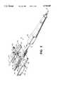
- FIG. 1is a front, top and right-side perspective view of an optical fiber connector
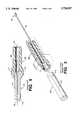
- FIG. 2is an exploded perspective view of the optical fiber connector shown in FIG. 1, illustrating its associated components;
- FIG. 3is an exploded perspective view of a prior art ferrule/base member assembly, shown in partial cross section for clarity;
- FIG. 4is a cross section view of the prior art assembly shown in FIG. 3;
- FIG. 5is a cross section of a ferrule/base member assembly in accordance with the invention.
- FIG. 6shows a drawn glass tube having an axial passageway and circumferential scores
- FIG. 7shows a ferrule, in cross section, having a uniform axial passageway along its entire length and a keyway on its surface
- FIG. 8is a perspective view of a ferrule/base member assembly in accordance with the invention, shown in partial cross section for clarity;
- FIG. 9is an exploded perspective view of a mold, in partial cross section, suitable for overmolding a base member onto a ferrule;
- FIG. 10is a cross-section view of the mold disclosed in FIG. 9, shown in its open position.
- FIG. 11is a cross-section view of the mold disclosed in FIG. 9, shown in its closed position.
- FIG. 1shows a front, top and right-side perspective view of an optical fiber connector 10 which, together with bend-limiting strain-relief boot 20, terminates optical cable 30.
- This optical fiber connectorhas a generally rectangular shape with a square cross section.
- the outside surface of the connector 10includes a spring latch 120 which is used for securing the connector to an associated receptacle in order to prevent unintended decoupling between the two.
- the connector and latchare molded from a commodity thermoplastic in order to achieve a low-cost, lightweight housing for optical components contained therein.
- Spring latch 120is molded into the housing and includes a "living hinge" 125 which allows tab 126 to be moved up and down in a direction which is perpendicular to the central axis 50--50 of connector 10.
- the connectorhas a footprint (cross-section dimension) of 4.6 by 4.6 millimeters (mm).
- Ferrule 140is shown protruding from opening 111 of a two-piece assembly comprising housing 110 and cover 100 which have been bonded together after the ferrule 140 and its associated components have been installed in the housing.
- One of the associated componentsis a spring which allows the ferrule to move back and forth through the opening 111.
- An end face 142 of the ferrulecomprises a polished flat or domed surface which abuts with the end face of another ferrule in a typical interconnection. The ferrule only protrudes slightly from the front end of the housing in order to protect it from damage if dropped.
- the ferrulemay be made from glass which needs greater protection than if made from plastic, metal and/or ceramic materials. Because the connector is small, and preferably uses lightweight materials with a low total mass, there is little fear that the connector (equipped with a glass ferrule) would be damaged if dropped.
- force Fis proportional to mass m, and in this case the constant a is the acceleration due to gravity.
- FIG. 2is an exploded perspective view of the optical connector shown in FIG. 1, illustrating its associated components.
- FIG. 2discloses construction details of a connector 10 which includes housing 110, cover 100, and a fiber-holding structure comprising ferrule 140, base member 150, and spring 160 which is disposed about the base member.
- housing 110which is a generally U-shaped device having a cavity 114 for receiving the fiber-holding structure. Once the fiber-holding structure is inserted into the cavity of housing 110, cover 100 is bonded thereto.
- Cover 100includes pins 106--106 which mate with holes 116--116 in housing 110 for alignment.
- Top surface 112 and left-side surface 101comprise two of the four outside surfaces that form the front end of connector 10.
- the back end of connector 10is conically shaped with four flat areas, spaced 90° apart, that are used to position the back end of the connector within the front end of strain-relief boot 20.
- Top surface 118 and left-side surface 102comprise two of the four flat surfaces at the back end of connector 10.
- Housing members 100,110include a plurality of interior surfaces that define cavity 114 which surrounds the fiber-carrying structure.
- the connectorincludes a first opening 119 at its back end which receives an optical cable 30 and a second opening 111 at its front end for enabling the end face of the fiber-carrying structure to protrude therethrough. These openings 111, 119 extend into cavity 114 and are positioned at opposite ends of connector 10.
- Housing members 100, 110are molded from a thermoplastic material and have been designed to be molded for straight pulls without cams to reduce mold and part costs. It is noted that spring latch 120 is molded into the top surface 112 of the housing 110.
- interior cavity 114also has a generally square shape.
- a flange 113 within housing 110includes a sloped surface which is shaped to interface with chamfered surface 154 of flange 152 on the base member 150.
- flange 152is shaped to enable it to be supported within cavity 114 in several different stable positions--each one having a different rotational orientation with respect to the central axis of the fiber-holding structure.
- Compression spring 160surrounds the back cylindrical portion of base member 150 and presses against surface 153 of flange 152 (see also FIG. 5) and against surface 115 within the cavity 114 of housing member 110. Spring 160 urges the end face of the fiber-holding structure through opening 111.
- Ferrule 140may be a glass, metal, ceramic or plastic cylinder having an axial passageway (about 0.13 mm in diameter) through its central axis for receiving an uncoated end portion of an optical fiber.
- the ferruleis made from a borosilicate glass and has an outer diameter of about 1.25 mm and a length of about 7.0 mm.
- a thin (about 0.125 mm diameter) glass fiber 35is typically coated with two layers of ultraviolet-curable materials such as a polyurethane polyacrylate for protection.
- a sheath systemsurrounds the coated fiber to protect it during handling and from environmental conditions.
- the sheath systemmay include any or all of the following items.
- the coated fibermay be covered with a thermoplastic material having sufficient stiffness to preclude fiber buckling thereby forming a buffered fiber 33.
- Strength members 32may surround the buffered fiber 33 so that it can withstand tensile forces that might otherwise fracture it.
- Elongated slender polymeric fibers of high tensile strength, such as aramid yam,are suitable for use in this regard.
- An outer jacket 31comprising polyvinyl chloride, for example, generally surrounds the buffered fiber and strength members to complete the construction of the optical cable.
- FIG. 3is an exploded perspective view of a prior art ferrule/base member assembly which is shown in partial cross section for clarity. All coating materials are removed from buffered fiber 33 in preparation for its insertion into ferrule/base member assembly 170/180.
- the ferrule 170 and base member 180are typically joined by an adhesive which undesirably enters funnel 173, during sub-assembly, and precludes the uncoated end portion 35 from entering passageway 175. As the components are reduced in size, the adhesive can frequently enter funnel 173. Accordingly, this prior art assembly process adds significantly to the overall ferrule/base member cost and needs improvement.
- FIG. 4is a cross section of the prior art ferrule/base member assembly shown in FIG. 3.
- Ferrule 170includes a narrow passageway 175 along its central axis 50--50 which extends from its front end face 172 to its back end face 171.
- end face 171is not identical to end face 172 because it includes an entry funnel 173 into the passageway.
- Such an entry funnelis required in the prior art to guide an optical fiber, with little clearance (typically less than 1 ⁇ m for singlemode) into the passageway 175. Manufacturing an entry funnel into the ferrule is an expensive step.
- Base member 180includes an axial bore 185 for receiving the optical fiber which must be coaxial with the ferrule after assembly in which the base member and ferrule are joined by press fitting or adhesive means. Manufacturing the ferrule/base member assembly can therefore be a bottleneck. Exemplary approximate dimensions of conventional ferrules are 2.5 mm outside diameter; 0.13 mm axial passageway diameter; and 12.5 mm length.
- the exemplary approximate dimensionsare 1.25 mm outside diameter; 0.13 mm axial passageway diameter; and 7.0 mm length. It is noted that assembly become more difficult as the outside ferrule diameter becomes smaller.
- FIG. 5illustrates a ferrule/base member assembly comprising ferrule 140 and base member 150 in accordance with the invention.
- Ferrule 140includes a narrow cylindrical passageway 145 along its central axis 50--50 which extends from its front end face 142 to its back end face 141.
- end face 141is similar to end face 142 in that it does not include an entry funnel into the passageway; and so, passageway 145 has a substantially constant diameter along its entire length (i.e., from end face 141 to end face 142).
- base member 150includes an axial bore 155 having an entry funnel 151 where the axial bore meets the end face 141 of ferrule 140.
- the ferrule and base membermay be press fitted together; however, this is a relatively expensive process due to the required accuracy.
- base member 150is overmolded onto ferrule 140 as discussed below.
- the use of a drawn glass ferrulehas certain advantages.
- the high hardness and strength of ceramic materials, which are typically used for making ferrules,are not required.
- standard polishing of the ferrule end facetypically results in a slightly convex ferrule end face, with possibly a slightly (on a microscopic scale) protruding fiber.
- This naturally occurring configurationmakes possible very efficient fiber coupling. Not only does the resulting intimate fiber-to-fiber contact result in low optical loss, but these connectors also have exceptionally low reflection of signal radiation.
- Reflection levels lower than -55 dBare commonly observed in prototypical connectors, and low reflection levels are desirable.
- standard polishing of the relatively hard ceramic ferrule end facestypically results in preferential removal of material from the fiber such that the fiber end face frequently becomes slightly concave. This in turn results in relatively poor coupling between fibers.
- the relatively hard debris from the polishing of the ceramic ferrule end facefrequently damages the fiber end face.
- drawn glass ferrulesare less expensive than ceramic ferrules, and can result in connectors that have better thermal properties and dimensional tolerances.
- FIG. 6shows a dram glass tube 600 having a passageway 145 along its central axis, and circumferential scores 149--149 that facilitate breaking. And although the scores are shown to be symmetrically beveled, it is not necessary.
- Using the draw process to manufacture ferrules 140--140is substantially the same as the draw process used in making optical fiber. This process provides a highly accurate end product whose cross-section dimensions are exactly proportional to the much larger tube from which it was drawn. Accordingly, making smaller diameter ferrules than have been conventionally used is not a problem when glass is used.
- FIG. 7shows a ferrule 140 having a uniform axial passageway 145 along its entire length and a keyway 148 on its surface.
- This keywaymay have virtually any shape, although it is shown here as being a flat notch which is positioned near the back end face 141 of the ferrule through which an uncoated end portion of an optical fiber is inserted into passageway 145.
- the keywayneeds to be located in that portion of the ferrule which resides within the base member after molding in order to preclude rotational movement of the ferrule.
- the keyway 148is positioned directly at the end face 141.
- the keyway 148is positioned a short distance away from the end face 141 so that, advantageously, a forward-facing surface 149 is available to keep the ferrule from being pulled out of the base member.
- FIG. 8there is disclosed an exploded perspective view of a ferrule/base member assembly in accordance with the invention.
- the overmolding processcauses a small amount of thermoplastic material to fill keyway 148 thereby keeping the ferrule 140 and base member 150 permanently joined in a particular alignment.
- the base memberincludes a molded funnel 151 which feeds fiber directly into passageway 145 of the ferrule so that the substantial expense and time required to etch or grind a funnel into the ferrule is eliminated.
- the molding process by which this is achievedis now described in connection with FIG. 9.
- FIG. 9A mold 900 which is suitable for overmolding a base member onto a glass or ceramic ferrule is shown in FIG. 9 in an exploded perspective cross section view.
- Mold 900is a tool steel block comprising portions 910 and 960 which are closed during the molding process. Prior to closing the mold, however, a ferrule 140 is inserted into a channel 914 up to ejector pin 920 within mold portion 910. When the mold is closed, channel 914 is coaxial with channel 964 within mold portion 960.
- core pin 950which resides in channel 964.
- the core pinis made from hardened steel and has a sharp conical point 951 at one end thereof.
- the conical pointhas a 60 degree included angle which engages end face 141 (not shown) of ferrule 140 by entering axial passageway 145 as the two mold halves come together.
- the ferrule 140is positioned against the conical point 951 of core pin 950.
- the core pinis spring loaded and allows a minimum of about 0.1 mm of axial movement. Ceramic ferrules are able to withstand a greater force from the spring-loaded core pin, before breaking, than glass ferrules.
- a spring force of 4.5 kgfis used when overmolding a ceramic ferrule, and a spring force of about 1.4 kgf is used when overmolding a glass ferrule.
- thermoplastic materialis injected into a channel formed by semicircular grooves 912, 962.
- polycarbonate plasticis used which is heated to approximately 200° C. and pressurized in the range 3.5-14 kgf/mm 2 .
- the mold itselfis maintained at about 93° C. so that it takes about 10-12 seconds for the polycarbonate plastic to cool sufficiently before opening the mold.
- the shape of the base membercorresponds to the open space within channel 964.
- the axial bore 155in the base member 150 has the shape of that portion of the core pin designated 955; and the entry funnel 151 at one end of the axial bore has the shape of that portion of the core pin designated 951.
- the pressure of the thermoplastic material itselfis used to lock the core pin in place. This is accomplished by directing the pressurized thermoplastic material into a channel formed by semicircular groove 913 so that it presses against actuator 980.
- the actuatortransfers this force to lever (brake) 970 which rotates around pivot pin 967 and presses against surface 957 of the core pin 950 to provide a braking force which keeps it stationary.
- the braking forceis proportional to the force which tends to move the core pin.
- FIGS. 10 and 11are cross-section views of the mold shown in FIG. 9 in the open and closed positions respectively.
- Ferrule 140is installed into channel 914 of mold portion 910 while the mold is open.
- a force, designated “F 1 " in FIG. 10is applied by a spring (not shown) against core pin 950 which holds it against wall 965 of the mold portion 960.
- the amount of force appliedneeds to be appropriate for the material used in the manufacture of the ferrule.
- the moldis then closed and ferrule 140 comes into contact with the tip 954 of core pin 950--thereby causing the core pin to move away from wall 965 by a distance "d," increasing the force to "F 2 ".
- High pressure thermoplastic materialis then injected into the channels formed by grooves 912, 962, 913 causing: (i) actuator 980 to press against brake 970; (ii) brake 970 to rotate around pivot 967 thereby engaging and locking core pin 950; and (iii) thermoplastic material to enter channels 915, 964 and form a structure (i.e., the base member) around ferrule 140.
- actuator 980to press against brake 970
- brake 970to rotate around pivot 967 thereby engaging and locking core pin 950
- thermoplastic materialto enter channels 915, 964 and form a structure (i.e., the base member) around ferrule 140.
- the moldis opened and ejector pin 920 is moved to eject the finished ferrule/base member assembly from the mold.
Landscapes
- Physics & Mathematics (AREA)
- General Physics & Mathematics (AREA)
- Optics & Photonics (AREA)
- Mechanical Coupling Of Light Guides (AREA)
- Casting Or Compression Moulding Of Plastics Or The Like (AREA)
Abstract
Description
Claims (5)
Priority Applications (4)
| Application Number | Priority Date | Filing Date | Title |
|---|---|---|---|
| US08/428,804US5720907A (en) | 1995-04-24 | 1995-04-24 | Method for manufacturing an optical connector assembly |
| JP09085196AJP3200011B2 (en) | 1995-04-24 | 1996-04-12 | Optical fiber connector manufacturing method and apparatus |
| DE69614303TDE69614303T2 (en) | 1995-04-24 | 1996-04-17 | Method and device for producing a fiber optic connector arrangement |
| EP96302693AEP0740174B1 (en) | 1995-04-24 | 1996-04-17 | Method and apparatus for manufacturing an optical connector assembly |
Applications Claiming Priority (1)
| Application Number | Priority Date | Filing Date | Title |
|---|---|---|---|
| US08/428,804US5720907A (en) | 1995-04-24 | 1995-04-24 | Method for manufacturing an optical connector assembly |
Publications (1)
| Publication Number | Publication Date |
|---|---|
| US5720907Atrue US5720907A (en) | 1998-02-24 |
Family
ID=23700469
Family Applications (1)
| Application Number | Title | Priority Date | Filing Date |
|---|---|---|---|
| US08/428,804Expired - Fee RelatedUS5720907A (en) | 1995-04-24 | 1995-04-24 | Method for manufacturing an optical connector assembly |
Country Status (4)
| Country | Link |
|---|---|
| US (1) | US5720907A (en) |
| EP (1) | EP0740174B1 (en) |
| JP (1) | JP3200011B2 (en) |
| DE (1) | DE69614303T2 (en) |
Cited By (14)
| Publication number | Priority date | Publication date | Assignee | Title |
|---|---|---|---|---|
| US6128927A (en)* | 1998-08-03 | 2000-10-10 | Lucent Technologies Inc. | Method of making ferrule connectors for optical fibers |
| US6439780B1 (en)* | 2000-08-31 | 2002-08-27 | Corning Cable Systems Llc | Field-installable fiber optic ribbon connector and installation tool |
| US20050031285A1 (en)* | 2000-03-22 | 2005-02-10 | Barnes Brandon A. | Multifiber connector, installation tool and associated methods of validating optical fiber continuity |
| US20050220923A1 (en)* | 2004-03-22 | 2005-10-06 | Shigekazu Yanagisawa | Three-dimensional hard copy apparatus |
| US20090310916A1 (en)* | 2006-08-15 | 2009-12-17 | Luther James P | Ruggedized Fiber Optic Connector Assembly |
| US20110002586A1 (en)* | 2009-04-06 | 2011-01-06 | Ponharith Nhep | Fiber optic connector and method for assembling |
| US20110103748A1 (en)* | 2009-11-04 | 2011-05-05 | Michael James Ott | Fiber optic ferrule assembly with transitioning insert |
| US20110158592A1 (en)* | 2009-12-30 | 2011-06-30 | Kerr Sean M | Ferrules Having An Anti-Rotation Feature And Fiber Optic Connectors Using The Same |
| US8388242B2 (en) | 2010-05-19 | 2013-03-05 | Adc Telecommunications, Inc. | In-line splice with integrated splice holder |
| US8939655B2 (en) | 2012-06-29 | 2015-01-27 | Corning Cable Systems Llc | Dust caps, fiber optic connectors, and fiber optic splitter modules incorporating interlocking key features |
| US9052469B2 (en) | 2013-04-26 | 2015-06-09 | Corning Cable Systems Llc | Preterminated fiber optic connector sub-assemblies, and related fiber optic connectors, cable assemblies, and methods |
| US9073249B2 (en)* | 2013-05-01 | 2015-07-07 | Fca Us Llc | Swivel side action for plastic injection molds |
| US11370184B2 (en)* | 2020-02-19 | 2022-06-28 | Anthony Nicholson | Cassette for securing fiber-optic cables and ferrules during the curing process |
| US11448846B2 (en) | 2017-04-17 | 2022-09-20 | Commscope Technologies Llc | Fiber routing systems |
Families Citing this family (7)
| Publication number | Priority date | Publication date | Assignee | Title |
|---|---|---|---|---|
| US6758603B2 (en)* | 2002-07-08 | 2004-07-06 | Hon Hai Precision Ind. Co., Ltd. | Optical connector assembly |
| EP2012153A1 (en)* | 2007-07-06 | 2009-01-07 | Ridgemount Technologies Limited | Optical fibre ferrule assembly |
| CN104823090B (en) | 2012-11-30 | 2017-04-05 | 泰科电子公司 | Fiber optic connectors with field-installable outer connector housings |
| CN104849815B (en) | 2014-02-14 | 2017-01-18 | 泰科电子(上海)有限公司 | Optical fiber connector and assembly method therefor |
| CN104849816B (en) | 2014-02-14 | 2017-01-11 | 泰科电子(上海)有限公司 | Optical fiber connector and assembly method therefor |
| CN105445862B (en) | 2014-07-09 | 2018-01-19 | 泰科电子(上海)有限公司 | The joints of optical fibre and its on-site assembly method |
| US10620385B2 (en) | 2015-11-30 | 2020-04-14 | Commscope Technologies Llc | Fiber optic connector and assembly thereof |
Citations (28)
| Publication number | Priority date | Publication date | Assignee | Title |
|---|---|---|---|---|
| US4107242A (en)* | 1975-11-11 | 1978-08-15 | Bell Telephone Laboratories, Incorporated | Method of fabricating optical fiber connectors |
| US4173389A (en)* | 1977-09-28 | 1979-11-06 | Bell Telephone Laboratories, Incorporated | Molded optical fiber connector |
| US4213932A (en)* | 1978-06-23 | 1980-07-22 | Bell Telephone Laboratories, Incorporated | Apparatus and method of molding a biconical socket |
| US4264128A (en)* | 1979-11-21 | 1981-04-28 | Bell Telephone Laboratories, Incorporated | Molded optical fiber connectors |
| US4292260A (en)* | 1980-09-22 | 1981-09-29 | Bell Telephone Laboratories, Incorporated | Molding optical fiber connectors |
| US4383964A (en)* | 1980-03-31 | 1983-05-17 | Henryk Prus | Process and machine for over-molding connectors on electrical conductors |
| US4424174A (en)* | 1982-06-18 | 1984-01-03 | Bell Telephone Laboratories, Incorporated | Fabrication of optical connectors |
| JPS60179708A (en)* | 1984-02-28 | 1985-09-13 | Shin Kobe Electric Mach Co Ltd | Manufacture of optical fiber connector |
| JPS6247308A (en)* | 1985-08-23 | 1987-03-02 | セントラル化成株式会社 | Production of perforated headrest with net |
| US4711752A (en)* | 1984-06-22 | 1987-12-08 | Itt Corporation | Method and apparatus for molding fiber optic connector ferrule |
| US4737009A (en)* | 1985-06-13 | 1988-04-12 | Sumitomo Electric Industries, Ltd. | Independent optical ferrule and optical fiber connector which uses the ferrule and replaceable optical plug using the ferrule |
| US4762584A (en)* | 1986-01-27 | 1988-08-09 | Lew Childre & Sons, Inc. | Method of molding a one piece integral fishing rod handle |
| US4834487A (en)* | 1988-09-29 | 1989-05-30 | Amp Incorporated | Optical connector with plastic alignment ferrule |
| JPH0216022A (en)* | 1988-07-04 | 1990-01-19 | Mitsubishi Cable Ind Ltd | Ferrule injection molding die |
| US4934785A (en)* | 1983-08-29 | 1990-06-19 | American Telephone And Telegraph Company | Optical fiber connector |
| US4942009A (en)* | 1985-09-27 | 1990-07-17 | Amp Incorporated | Method of Manufacturing a ferrule |
| US5013495A (en)* | 1988-02-05 | 1991-05-07 | Tokai Rubber Industries, Ltd. | Method of producing optical fiber connectors |
| US5016970A (en)* | 1989-08-22 | 1991-05-21 | Nippon Telegraph And Telephone Corp. | Ferrule for optical fiber transmitting linearly polarized light and optical fiber connector using this ferrule |
| US5101463A (en)* | 1991-05-03 | 1992-03-31 | Minnesota Mining And Manufacturing Company | Push-pull optical fiber connector |
| EP0490541A1 (en)* | 1990-12-10 | 1992-06-17 | The Whitaker Corporation | Active device mount with mark prevention |
| US5182032A (en)* | 1990-07-09 | 1993-01-26 | Paige Manufacturing Company Incorporated | Apparatus for plastic injection overmolding |
| US5216733A (en)* | 1991-03-11 | 1993-06-01 | Nippon Telegraph And Telephone Corporation | Polarization maintaining optical fiber connector including positioning flange and method utilizing same |
| US5216734A (en)* | 1992-06-12 | 1993-06-01 | Amp Incorporated | Fiber optic connector having low cost ferrule |
| US5269998A (en)* | 1991-05-24 | 1993-12-14 | The Furukawa Electric Co., Ltd. | Method of forming ferrule for an optical fiber connector and a mold therefor |
| US5307431A (en)* | 1991-10-04 | 1994-04-26 | France Telecom | Overmolded ferrule for connecting fibers and a method for preparing the same |
| US5375183A (en)* | 1993-05-25 | 1994-12-20 | The Whitaker Corporation | Overmolded alignment ferrule |
| US5439370A (en)* | 1992-03-24 | 1995-08-08 | Framatome Connectors International | Device for molding plastic material ferrule for optical fiber connectors |
| US5482451A (en)* | 1992-12-03 | 1996-01-09 | E. I. Du Pont De Nemours | Apparatus for the preparation of optical ferrules |
Family Cites Families (1)
| Publication number | Priority date | Publication date | Assignee | Title |
|---|---|---|---|---|
| JPS62247308A (en)* | 1986-04-15 | 1987-10-28 | Sumitomo Electric Ind Ltd | Multi-core optical connector ferrule and its manufacturing method |
- 1995
- 1995-04-24USUS08/428,804patent/US5720907A/ennot_activeExpired - Fee Related
- 1996
- 1996-04-12JPJP09085196Apatent/JP3200011B2/ennot_activeExpired - Fee Related
- 1996-04-17DEDE69614303Tpatent/DE69614303T2/ennot_activeExpired - Fee Related
- 1996-04-17EPEP96302693Apatent/EP0740174B1/ennot_activeExpired - Lifetime
Patent Citations (28)
| Publication number | Priority date | Publication date | Assignee | Title |
|---|---|---|---|---|
| US4107242A (en)* | 1975-11-11 | 1978-08-15 | Bell Telephone Laboratories, Incorporated | Method of fabricating optical fiber connectors |
| US4173389A (en)* | 1977-09-28 | 1979-11-06 | Bell Telephone Laboratories, Incorporated | Molded optical fiber connector |
| US4213932A (en)* | 1978-06-23 | 1980-07-22 | Bell Telephone Laboratories, Incorporated | Apparatus and method of molding a biconical socket |
| US4264128A (en)* | 1979-11-21 | 1981-04-28 | Bell Telephone Laboratories, Incorporated | Molded optical fiber connectors |
| US4383964A (en)* | 1980-03-31 | 1983-05-17 | Henryk Prus | Process and machine for over-molding connectors on electrical conductors |
| US4292260A (en)* | 1980-09-22 | 1981-09-29 | Bell Telephone Laboratories, Incorporated | Molding optical fiber connectors |
| US4424174A (en)* | 1982-06-18 | 1984-01-03 | Bell Telephone Laboratories, Incorporated | Fabrication of optical connectors |
| US4934785A (en)* | 1983-08-29 | 1990-06-19 | American Telephone And Telegraph Company | Optical fiber connector |
| JPS60179708A (en)* | 1984-02-28 | 1985-09-13 | Shin Kobe Electric Mach Co Ltd | Manufacture of optical fiber connector |
| US4711752A (en)* | 1984-06-22 | 1987-12-08 | Itt Corporation | Method and apparatus for molding fiber optic connector ferrule |
| US4737009A (en)* | 1985-06-13 | 1988-04-12 | Sumitomo Electric Industries, Ltd. | Independent optical ferrule and optical fiber connector which uses the ferrule and replaceable optical plug using the ferrule |
| JPS6247308A (en)* | 1985-08-23 | 1987-03-02 | セントラル化成株式会社 | Production of perforated headrest with net |
| US4942009A (en)* | 1985-09-27 | 1990-07-17 | Amp Incorporated | Method of Manufacturing a ferrule |
| US4762584A (en)* | 1986-01-27 | 1988-08-09 | Lew Childre & Sons, Inc. | Method of molding a one piece integral fishing rod handle |
| US5013495A (en)* | 1988-02-05 | 1991-05-07 | Tokai Rubber Industries, Ltd. | Method of producing optical fiber connectors |
| JPH0216022A (en)* | 1988-07-04 | 1990-01-19 | Mitsubishi Cable Ind Ltd | Ferrule injection molding die |
| US4834487A (en)* | 1988-09-29 | 1989-05-30 | Amp Incorporated | Optical connector with plastic alignment ferrule |
| US5016970A (en)* | 1989-08-22 | 1991-05-21 | Nippon Telegraph And Telephone Corp. | Ferrule for optical fiber transmitting linearly polarized light and optical fiber connector using this ferrule |
| US5182032A (en)* | 1990-07-09 | 1993-01-26 | Paige Manufacturing Company Incorporated | Apparatus for plastic injection overmolding |
| EP0490541A1 (en)* | 1990-12-10 | 1992-06-17 | The Whitaker Corporation | Active device mount with mark prevention |
| US5216733A (en)* | 1991-03-11 | 1993-06-01 | Nippon Telegraph And Telephone Corporation | Polarization maintaining optical fiber connector including positioning flange and method utilizing same |
| US5101463A (en)* | 1991-05-03 | 1992-03-31 | Minnesota Mining And Manufacturing Company | Push-pull optical fiber connector |
| US5269998A (en)* | 1991-05-24 | 1993-12-14 | The Furukawa Electric Co., Ltd. | Method of forming ferrule for an optical fiber connector and a mold therefor |
| US5307431A (en)* | 1991-10-04 | 1994-04-26 | France Telecom | Overmolded ferrule for connecting fibers and a method for preparing the same |
| US5439370A (en)* | 1992-03-24 | 1995-08-08 | Framatome Connectors International | Device for molding plastic material ferrule for optical fiber connectors |
| US5216734A (en)* | 1992-06-12 | 1993-06-01 | Amp Incorporated | Fiber optic connector having low cost ferrule |
| US5482451A (en)* | 1992-12-03 | 1996-01-09 | E. I. Du Pont De Nemours | Apparatus for the preparation of optical ferrules |
| US5375183A (en)* | 1993-05-25 | 1994-12-20 | The Whitaker Corporation | Overmolded alignment ferrule |
Non-Patent Citations (2)
| Title |
|---|
| Optical Fiber Telecommunications II, 301 325 (Stewart E. Miller, et al. eds 1988).* |
| Optical Fiber Telecommunications II, 301-325 (Stewart E. Miller, et al. eds 1988). |
Cited By (23)
| Publication number | Priority date | Publication date | Assignee | Title |
|---|---|---|---|---|
| US6128927A (en)* | 1998-08-03 | 2000-10-10 | Lucent Technologies Inc. | Method of making ferrule connectors for optical fibers |
| US20050031285A1 (en)* | 2000-03-22 | 2005-02-10 | Barnes Brandon A. | Multifiber connector, installation tool and associated methods of validating optical fiber continuity |
| US6931193B2 (en)* | 2000-03-22 | 2005-08-16 | Corning Cable Systems Llc | Multifiber connector, installation tool and associated methods of validating optical fiber continuity |
| US6439780B1 (en)* | 2000-08-31 | 2002-08-27 | Corning Cable Systems Llc | Field-installable fiber optic ribbon connector and installation tool |
| US20050220923A1 (en)* | 2004-03-22 | 2005-10-06 | Shigekazu Yanagisawa | Three-dimensional hard copy apparatus |
| US7311512B2 (en)* | 2004-03-22 | 2007-12-25 | Seiko Epson Corporation | Three-dimensional hard copy apparatus |
| US20090310916A1 (en)* | 2006-08-15 | 2009-12-17 | Luther James P | Ruggedized Fiber Optic Connector Assembly |
| US8523455B2 (en)* | 2006-08-15 | 2013-09-03 | Corning Cable Systems Llc | Ruggedized fiber optic connector assembly |
| US8342755B2 (en) | 2009-04-06 | 2013-01-01 | Adc Telecommunications, Inc. | Fiber optic connector and method for assembling |
| US20110002586A1 (en)* | 2009-04-06 | 2011-01-06 | Ponharith Nhep | Fiber optic connector and method for assembling |
| US8702320B2 (en) | 2009-11-04 | 2014-04-22 | Adc Telecommunications, Inc. | Fiber optic ferrule assembly with transitioning insert |
| US20110103748A1 (en)* | 2009-11-04 | 2011-05-05 | Michael James Ott | Fiber optic ferrule assembly with transitioning insert |
| CN102667563A (en)* | 2009-12-30 | 2012-09-12 | 康宁光缆系统有限责任公司 | Ferrules having an anti-rotation feature and fiber optic connectors using the same |
| US8496386B2 (en)* | 2009-12-30 | 2013-07-30 | Corning Cable Systems Llc | Ferrules having an anti-rotation feature and fiber optic connectors using the same |
| US20110158592A1 (en)* | 2009-12-30 | 2011-06-30 | Kerr Sean M | Ferrules Having An Anti-Rotation Feature And Fiber Optic Connectors Using The Same |
| CN102667563B (en)* | 2009-12-30 | 2015-11-25 | 康宁光缆系统有限责任公司 | There is the sleeve pipe of anti-rotational feature structure and use the joints of optical fibre of sleeve pipe |
| US8388242B2 (en) | 2010-05-19 | 2013-03-05 | Adc Telecommunications, Inc. | In-line splice with integrated splice holder |
| US8939655B2 (en) | 2012-06-29 | 2015-01-27 | Corning Cable Systems Llc | Dust caps, fiber optic connectors, and fiber optic splitter modules incorporating interlocking key features |
| US9052469B2 (en) | 2013-04-26 | 2015-06-09 | Corning Cable Systems Llc | Preterminated fiber optic connector sub-assemblies, and related fiber optic connectors, cable assemblies, and methods |
| US9151905B2 (en) | 2013-04-26 | 2015-10-06 | Corning Optical Communications LLC | Preterminated fiber optic connector sub-assemblies, and related fiber optic connectors, cable assemblies, and methods |
| US9073249B2 (en)* | 2013-05-01 | 2015-07-07 | Fca Us Llc | Swivel side action for plastic injection molds |
| US11448846B2 (en) | 2017-04-17 | 2022-09-20 | Commscope Technologies Llc | Fiber routing systems |
| US11370184B2 (en)* | 2020-02-19 | 2022-06-28 | Anthony Nicholson | Cassette for securing fiber-optic cables and ferrules during the curing process |
Also Published As
| Publication number | Publication date |
|---|---|
| DE69614303D1 (en) | 2001-09-13 |
| JP3200011B2 (en) | 2001-08-20 |
| EP0740174A3 (en) | 1997-01-08 |
| JPH08294928A (en) | 1996-11-12 |
| EP0740174B1 (en) | 2001-08-08 |
| EP0740174A2 (en) | 1996-10-30 |
| DE69614303T2 (en) | 2004-02-05 |
Similar Documents
| Publication | Publication Date | Title |
|---|---|---|
| US5720907A (en) | Method for manufacturing an optical connector assembly | |
| US5923805A (en) | Connector for plastic optical fiber | |
| US5481634A (en) | Connector for optical fiber | |
| US5719977A (en) | Optical connector with immovable ferrule | |
| US5734770A (en) | Cleave and bevel fiber optic connector | |
| US4107242A (en) | Method of fabricating optical fiber connectors | |
| CA2225737A1 (en) | Bare fiber connector | |
| US5390269A (en) | Fiber optic connector with high resolution tunable fiber holder | |
| US4743084A (en) | Optical fiber connector for field application | |
| US5796894A (en) | Fiber optic connector with improved return loss performance | |
| EP0895106B1 (en) | Method of fabricating a fiber optic connector ferrule | |
| AU692111B2 (en) | Fiber optic connector element | |
| EP0860722A2 (en) | Fiber optic connector with improved return loss performance and method of fabricating same | |
| US4836637A (en) | Expanded-beam fiber-optic connector | |
| EP1039323A1 (en) | Ferrule for optical fibres | |
| US20020159729A1 (en) | Optical fiber array | |
| EP0112379B1 (en) | Fabrication of optical connectors | |
| EP0737877A2 (en) | Optical connector assembly | |
| EP0574462B1 (en) | Fibre optics connector and a method of making the same | |
| US5307431A (en) | Overmolded ferrule for connecting fibers and a method for preparing the same | |
| US11175461B2 (en) | Fiber alignment device with curved portions | |
| Sato et al. | Injection moulded optical alignment sleeve for singlemode connection | |
| GB2033099A (en) | Terminating optical fibres | |
| CA1267801A (en) | Optical fiber junction devices | |
| Hayashi | Optical Connectors |
Legal Events
| Date | Code | Title | Description |
|---|---|---|---|
| AS | Assignment | Owner name:AT&T IPM CORP., FLORIDA Free format text:ASSIGNMENT OF ASSIGNORS INTEREST;ASSIGNORS:ANDERSON, J. M.;LAMPERT, N. R.;SHEVCHUCK, G. S.;REEL/FRAME:007493/0228;SIGNING DATES FROM 19950419 TO 19950420 | |
| AS | Assignment | Owner name:LUCENT TECHNOLOGIES INC., NEW JERSEY Free format text:ASSIGNMENT OF ASSIGNORS INTEREST;ASSIGNOR:AT&T CORP.;REEL/FRAME:008697/0789 Effective date:19960329 | |
| FEPP | Fee payment procedure | Free format text:PAYOR NUMBER ASSIGNED (ORIGINAL EVENT CODE: ASPN); ENTITY STATUS OF PATENT OWNER: LARGE ENTITY | |
| AS | Assignment | Owner name:THE CHASE MANHATTAN BANK, AS COLLATERAL AGENT, TEX Free format text:CONDITIONAL ASSIGNMENT OF AND SECURITY INTEREST IN PATENT RIGHTS;ASSIGNOR:LUCENT TECHNOLOGIES INC. (DE CORPORATION);REEL/FRAME:011722/0048 Effective date:20010222 | |
| FPAY | Fee payment | Year of fee payment:4 | |
| AS | Assignment | Owner name:LUCENT TECHNOLOGIES INC., NEW JERSEY Free format text:ASSIGNMENT OF ASSIGNORS INTEREST;ASSIGNOR:AT&T CORP.;REEL/FRAME:012059/0893 Effective date:19960329 | |
| AS | Assignment | Owner name:LUCENT TECHNOLOGIES INC., NEW JERSEY Free format text:PARTIAL TERMINATION AND RELEASE OF SECURITY INTEREST.;ASSIGNOR:JPMORGAN CHASE BANK (F/K/A THE CHASE MANHATTAN BANK);REEL/FRAME:012495/0128 Effective date:20011116 | |
| AS | Assignment | Owner name:FITEL USA CORPORATION, GEORGIA Free format text:ASSIGNMENT OF ASSIGNORS INTEREST;ASSIGNOR:LUCENT TECHNOLOGIES;REEL/FRAME:012946/0578 Effective date:20011116 | |
| REMI | Maintenance fee reminder mailed | ||
| LAPS | Lapse for failure to pay maintenance fees | ||
| STCH | Information on status: patent discontinuation | Free format text:PATENT EXPIRED DUE TO NONPAYMENT OF MAINTENANCE FEES UNDER 37 CFR 1.362 | |
| FP | Lapsed due to failure to pay maintenance fee | Effective date:20060224 |