US5720748A - Spinal stabilization surgical apparatus - Google Patents
Spinal stabilization surgical apparatusDownload PDFInfo
- Publication number
- US5720748A US5720748AUS08/482,025US48202595AUS5720748AUS 5720748 AUS5720748 AUS 5720748AUS 48202595 AUS48202595 AUS 48202595AUS 5720748 AUS5720748 AUS 5720748A
- Authority
- US
- United States
- Prior art keywords
- drill tube
- implant
- guide
- vertebrae
- sized
- Prior art date
- Legal status (The legal status is an assumption and is not a legal conclusion. Google has not performed a legal analysis and makes no representation as to the accuracy of the status listed.)
- Expired - Lifetime
Links
Images


Classifications
- A—HUMAN NECESSITIES
- A61—MEDICAL OR VETERINARY SCIENCE; HYGIENE
- A61B—DIAGNOSIS; SURGERY; IDENTIFICATION
- A61B17/00—Surgical instruments, devices or methods
- A61B17/16—Instruments for performing osteoclasis; Drills or chisels for bones; Trepans
- A61B17/17—Guides or aligning means for drills, mills, pins or wires
- A61B17/1739—Guides or aligning means for drills, mills, pins or wires specially adapted for particular parts of the body
- A61B17/1757—Guides or aligning means for drills, mills, pins or wires specially adapted for particular parts of the body for the spine
- A—HUMAN NECESSITIES
- A61—MEDICAL OR VETERINARY SCIENCE; HYGIENE
- A61F—FILTERS IMPLANTABLE INTO BLOOD VESSELS; PROSTHESES; DEVICES PROVIDING PATENCY TO, OR PREVENTING COLLAPSING OF, TUBULAR STRUCTURES OF THE BODY, e.g. STENTS; ORTHOPAEDIC, NURSING OR CONTRACEPTIVE DEVICES; FOMENTATION; TREATMENT OR PROTECTION OF EYES OR EARS; BANDAGES, DRESSINGS OR ABSORBENT PADS; FIRST-AID KITS
- A61F2/00—Filters implantable into blood vessels; Prostheses, i.e. artificial substitutes or replacements for parts of the body; Appliances for connecting them with the body; Devices providing patency to, or preventing collapsing of, tubular structures of the body, e.g. stents
- A61F2/02—Prostheses implantable into the body
- A61F2/30—Joints
- A61F2/30721—Accessories
- A61F2/30744—End caps, e.g. for closing an endoprosthetic cavity
- A—HUMAN NECESSITIES
- A61—MEDICAL OR VETERINARY SCIENCE; HYGIENE
- A61F—FILTERS IMPLANTABLE INTO BLOOD VESSELS; PROSTHESES; DEVICES PROVIDING PATENCY TO, OR PREVENTING COLLAPSING OF, TUBULAR STRUCTURES OF THE BODY, e.g. STENTS; ORTHOPAEDIC, NURSING OR CONTRACEPTIVE DEVICES; FOMENTATION; TREATMENT OR PROTECTION OF EYES OR EARS; BANDAGES, DRESSINGS OR ABSORBENT PADS; FIRST-AID KITS
- A61F2/00—Filters implantable into blood vessels; Prostheses, i.e. artificial substitutes or replacements for parts of the body; Appliances for connecting them with the body; Devices providing patency to, or preventing collapsing of, tubular structures of the body, e.g. stents
- A61F2/02—Prostheses implantable into the body
- A61F2/30—Joints
- A61F2/44—Joints for the spine, e.g. vertebrae, spinal discs
- A61F2/4455—Joints for the spine, e.g. vertebrae, spinal discs for the fusion of spinal bodies, e.g. intervertebral fusion of adjacent spinal bodies, e.g. fusion cages
- A61F2/446—Joints for the spine, e.g. vertebrae, spinal discs for the fusion of spinal bodies, e.g. intervertebral fusion of adjacent spinal bodies, e.g. fusion cages having a circular or elliptical cross-section substantially parallel to the axis of the spine, e.g. cylinders or frustocones
- A—HUMAN NECESSITIES
- A61—MEDICAL OR VETERINARY SCIENCE; HYGIENE
- A61F—FILTERS IMPLANTABLE INTO BLOOD VESSELS; PROSTHESES; DEVICES PROVIDING PATENCY TO, OR PREVENTING COLLAPSING OF, TUBULAR STRUCTURES OF THE BODY, e.g. STENTS; ORTHOPAEDIC, NURSING OR CONTRACEPTIVE DEVICES; FOMENTATION; TREATMENT OR PROTECTION OF EYES OR EARS; BANDAGES, DRESSINGS OR ABSORBENT PADS; FIRST-AID KITS
- A61F2/00—Filters implantable into blood vessels; Prostheses, i.e. artificial substitutes or replacements for parts of the body; Appliances for connecting them with the body; Devices providing patency to, or preventing collapsing of, tubular structures of the body, e.g. stents
- A61F2/02—Prostheses implantable into the body
- A61F2/30—Joints
- A61F2/46—Special tools for implanting artificial joints
- A61F2/4603—Special tools for implanting artificial joints for insertion or extraction of endoprosthetic joints or of accessories thereof
- A61F2/4611—Special tools for implanting artificial joints for insertion or extraction of endoprosthetic joints or of accessories thereof of spinal prostheses
- A—HUMAN NECESSITIES
- A61—MEDICAL OR VETERINARY SCIENCE; HYGIENE
- A61B—DIAGNOSIS; SURGERY; IDENTIFICATION
- A61B17/00—Surgical instruments, devices or methods
- A61B17/56—Surgical instruments or methods for treatment of bones or joints; Devices specially adapted therefor
- A61B17/58—Surgical instruments or methods for treatment of bones or joints; Devices specially adapted therefor for osteosynthesis, e.g. bone plates, screws or setting implements
- A61B17/68—Internal fixation devices, including fasteners and spinal fixators, even if a part thereof projects from the skin
- A61B17/84—Fasteners therefor or fasteners being internal fixation devices
- A61B17/86—Pins or screws or threaded wires; nuts therefor
- A—HUMAN NECESSITIES
- A61—MEDICAL OR VETERINARY SCIENCE; HYGIENE
- A61B—DIAGNOSIS; SURGERY; IDENTIFICATION
- A61B17/00—Surgical instruments, devices or methods
- A61B17/02—Surgical instruments, devices or methods for holding wounds open, e.g. retractors; Tractors
- A61B17/025—Joint distractors
- A61B2017/0256—Joint distractors for the spine
- A—HUMAN NECESSITIES
- A61—MEDICAL OR VETERINARY SCIENCE; HYGIENE
- A61F—FILTERS IMPLANTABLE INTO BLOOD VESSELS; PROSTHESES; DEVICES PROVIDING PATENCY TO, OR PREVENTING COLLAPSING OF, TUBULAR STRUCTURES OF THE BODY, e.g. STENTS; ORTHOPAEDIC, NURSING OR CONTRACEPTIVE DEVICES; FOMENTATION; TREATMENT OR PROTECTION OF EYES OR EARS; BANDAGES, DRESSINGS OR ABSORBENT PADS; FIRST-AID KITS
- A61F2/00—Filters implantable into blood vessels; Prostheses, i.e. artificial substitutes or replacements for parts of the body; Appliances for connecting them with the body; Devices providing patency to, or preventing collapsing of, tubular structures of the body, e.g. stents
- A61F2/02—Prostheses implantable into the body
- A61F2/30—Joints
- A61F2/30721—Accessories
- A61F2/30723—Plugs or restrictors for sealing a cement-receiving space
- A—HUMAN NECESSITIES
- A61—MEDICAL OR VETERINARY SCIENCE; HYGIENE
- A61F—FILTERS IMPLANTABLE INTO BLOOD VESSELS; PROSTHESES; DEVICES PROVIDING PATENCY TO, OR PREVENTING COLLAPSING OF, TUBULAR STRUCTURES OF THE BODY, e.g. STENTS; ORTHOPAEDIC, NURSING OR CONTRACEPTIVE DEVICES; FOMENTATION; TREATMENT OR PROTECTION OF EYES OR EARS; BANDAGES, DRESSINGS OR ABSORBENT PADS; FIRST-AID KITS
- A61F2/00—Filters implantable into blood vessels; Prostheses, i.e. artificial substitutes or replacements for parts of the body; Appliances for connecting them with the body; Devices providing patency to, or preventing collapsing of, tubular structures of the body, e.g. stents
- A61F2/02—Prostheses implantable into the body
- A61F2/30—Joints
- A61F2/44—Joints for the spine, e.g. vertebrae, spinal discs
- A61F2/442—Intervertebral or spinal discs, e.g. resilient
- A—HUMAN NECESSITIES
- A61—MEDICAL OR VETERINARY SCIENCE; HYGIENE
- A61F—FILTERS IMPLANTABLE INTO BLOOD VESSELS; PROSTHESES; DEVICES PROVIDING PATENCY TO, OR PREVENTING COLLAPSING OF, TUBULAR STRUCTURES OF THE BODY, e.g. STENTS; ORTHOPAEDIC, NURSING OR CONTRACEPTIVE DEVICES; FOMENTATION; TREATMENT OR PROTECTION OF EYES OR EARS; BANDAGES, DRESSINGS OR ABSORBENT PADS; FIRST-AID KITS
- A61F2/00—Filters implantable into blood vessels; Prostheses, i.e. artificial substitutes or replacements for parts of the body; Appliances for connecting them with the body; Devices providing patency to, or preventing collapsing of, tubular structures of the body, e.g. stents
- A61F2/02—Prostheses implantable into the body
- A61F2/30—Joints
- A61F2/44—Joints for the spine, e.g. vertebrae, spinal discs
- A61F2/4455—Joints for the spine, e.g. vertebrae, spinal discs for the fusion of spinal bodies, e.g. intervertebral fusion of adjacent spinal bodies, e.g. fusion cages
- A—HUMAN NECESSITIES
- A61—MEDICAL OR VETERINARY SCIENCE; HYGIENE
- A61F—FILTERS IMPLANTABLE INTO BLOOD VESSELS; PROSTHESES; DEVICES PROVIDING PATENCY TO, OR PREVENTING COLLAPSING OF, TUBULAR STRUCTURES OF THE BODY, e.g. STENTS; ORTHOPAEDIC, NURSING OR CONTRACEPTIVE DEVICES; FOMENTATION; TREATMENT OR PROTECTION OF EYES OR EARS; BANDAGES, DRESSINGS OR ABSORBENT PADS; FIRST-AID KITS
- A61F2/00—Filters implantable into blood vessels; Prostheses, i.e. artificial substitutes or replacements for parts of the body; Appliances for connecting them with the body; Devices providing patency to, or preventing collapsing of, tubular structures of the body, e.g. stents
- A61F2/02—Prostheses implantable into the body
- A61F2/30—Joints
- A61F2/46—Special tools for implanting artificial joints
- A61F2/4637—Special tools for implanting artificial joints for connecting or disconnecting two parts of a prosthesis
- A—HUMAN NECESSITIES
- A61—MEDICAL OR VETERINARY SCIENCE; HYGIENE
- A61F—FILTERS IMPLANTABLE INTO BLOOD VESSELS; PROSTHESES; DEVICES PROVIDING PATENCY TO, OR PREVENTING COLLAPSING OF, TUBULAR STRUCTURES OF THE BODY, e.g. STENTS; ORTHOPAEDIC, NURSING OR CONTRACEPTIVE DEVICES; FOMENTATION; TREATMENT OR PROTECTION OF EYES OR EARS; BANDAGES, DRESSINGS OR ABSORBENT PADS; FIRST-AID KITS
- A61F2/00—Filters implantable into blood vessels; Prostheses, i.e. artificial substitutes or replacements for parts of the body; Appliances for connecting them with the body; Devices providing patency to, or preventing collapsing of, tubular structures of the body, e.g. stents
- A61F2/02—Prostheses implantable into the body
- A61F2/28—Bones
- A61F2002/2835—Bone graft implants for filling a bony defect or an endoprosthesis cavity, e.g. by synthetic material or biological material
- A—HUMAN NECESSITIES
- A61—MEDICAL OR VETERINARY SCIENCE; HYGIENE
- A61F—FILTERS IMPLANTABLE INTO BLOOD VESSELS; PROSTHESES; DEVICES PROVIDING PATENCY TO, OR PREVENTING COLLAPSING OF, TUBULAR STRUCTURES OF THE BODY, e.g. STENTS; ORTHOPAEDIC, NURSING OR CONTRACEPTIVE DEVICES; FOMENTATION; TREATMENT OR PROTECTION OF EYES OR EARS; BANDAGES, DRESSINGS OR ABSORBENT PADS; FIRST-AID KITS
- A61F2/00—Filters implantable into blood vessels; Prostheses, i.e. artificial substitutes or replacements for parts of the body; Appliances for connecting them with the body; Devices providing patency to, or preventing collapsing of, tubular structures of the body, e.g. stents
- A61F2/02—Prostheses implantable into the body
- A61F2/30—Joints
- A61F2002/30001—Additional features of subject-matter classified in A61F2/28, A61F2/30 and subgroups thereof
- A61F2002/30108—Shapes
- A61F2002/30199—Three-dimensional shapes
- A61F2002/30224—Three-dimensional shapes cylindrical
- A61F2002/30235—Three-dimensional shapes cylindrical tubular, e.g. sleeves
- A—HUMAN NECESSITIES
- A61—MEDICAL OR VETERINARY SCIENCE; HYGIENE
- A61F—FILTERS IMPLANTABLE INTO BLOOD VESSELS; PROSTHESES; DEVICES PROVIDING PATENCY TO, OR PREVENTING COLLAPSING OF, TUBULAR STRUCTURES OF THE BODY, e.g. STENTS; ORTHOPAEDIC, NURSING OR CONTRACEPTIVE DEVICES; FOMENTATION; TREATMENT OR PROTECTION OF EYES OR EARS; BANDAGES, DRESSINGS OR ABSORBENT PADS; FIRST-AID KITS
- A61F2/00—Filters implantable into blood vessels; Prostheses, i.e. artificial substitutes or replacements for parts of the body; Appliances for connecting them with the body; Devices providing patency to, or preventing collapsing of, tubular structures of the body, e.g. stents
- A61F2/02—Prostheses implantable into the body
- A61F2/30—Joints
- A61F2002/30001—Additional features of subject-matter classified in A61F2/28, A61F2/30 and subgroups thereof
- A61F2002/30316—The prosthesis having different structural features at different locations within the same prosthesis; Connections between prosthetic parts; Special structural features of bone or joint prostheses not otherwise provided for
- A61F2002/30329—Connections or couplings between prosthetic parts, e.g. between modular parts; Connecting elements
- A61F2002/30476—Connections or couplings between prosthetic parts, e.g. between modular parts; Connecting elements locked by an additional locking mechanism
- A61F2002/305—Snap connection
- A—HUMAN NECESSITIES
- A61—MEDICAL OR VETERINARY SCIENCE; HYGIENE
- A61F—FILTERS IMPLANTABLE INTO BLOOD VESSELS; PROSTHESES; DEVICES PROVIDING PATENCY TO, OR PREVENTING COLLAPSING OF, TUBULAR STRUCTURES OF THE BODY, e.g. STENTS; ORTHOPAEDIC, NURSING OR CONTRACEPTIVE DEVICES; FOMENTATION; TREATMENT OR PROTECTION OF EYES OR EARS; BANDAGES, DRESSINGS OR ABSORBENT PADS; FIRST-AID KITS
- A61F2/00—Filters implantable into blood vessels; Prostheses, i.e. artificial substitutes or replacements for parts of the body; Appliances for connecting them with the body; Devices providing patency to, or preventing collapsing of, tubular structures of the body, e.g. stents
- A61F2/02—Prostheses implantable into the body
- A61F2/30—Joints
- A61F2002/30001—Additional features of subject-matter classified in A61F2/28, A61F2/30 and subgroups thereof
- A61F2002/30316—The prosthesis having different structural features at different locations within the same prosthesis; Connections between prosthetic parts; Special structural features of bone or joint prostheses not otherwise provided for
- A61F2002/30535—Special structural features of bone or joint prostheses not otherwise provided for
- A61F2002/30593—Special structural features of bone or joint prostheses not otherwise provided for hollow
- A—HUMAN NECESSITIES
- A61—MEDICAL OR VETERINARY SCIENCE; HYGIENE
- A61F—FILTERS IMPLANTABLE INTO BLOOD VESSELS; PROSTHESES; DEVICES PROVIDING PATENCY TO, OR PREVENTING COLLAPSING OF, TUBULAR STRUCTURES OF THE BODY, e.g. STENTS; ORTHOPAEDIC, NURSING OR CONTRACEPTIVE DEVICES; FOMENTATION; TREATMENT OR PROTECTION OF EYES OR EARS; BANDAGES, DRESSINGS OR ABSORBENT PADS; FIRST-AID KITS
- A61F2/00—Filters implantable into blood vessels; Prostheses, i.e. artificial substitutes or replacements for parts of the body; Appliances for connecting them with the body; Devices providing patency to, or preventing collapsing of, tubular structures of the body, e.g. stents
- A61F2/02—Prostheses implantable into the body
- A61F2/30—Joints
- A61F2002/30001—Additional features of subject-matter classified in A61F2/28, A61F2/30 and subgroups thereof
- A61F2002/30667—Features concerning an interaction with the environment or a particular use of the prosthesis
- A61F2002/30672—Features concerning an interaction with the environment or a particular use of the prosthesis temporary
- A—HUMAN NECESSITIES
- A61—MEDICAL OR VETERINARY SCIENCE; HYGIENE
- A61F—FILTERS IMPLANTABLE INTO BLOOD VESSELS; PROSTHESES; DEVICES PROVIDING PATENCY TO, OR PREVENTING COLLAPSING OF, TUBULAR STRUCTURES OF THE BODY, e.g. STENTS; ORTHOPAEDIC, NURSING OR CONTRACEPTIVE DEVICES; FOMENTATION; TREATMENT OR PROTECTION OF EYES OR EARS; BANDAGES, DRESSINGS OR ABSORBENT PADS; FIRST-AID KITS
- A61F2/00—Filters implantable into blood vessels; Prostheses, i.e. artificial substitutes or replacements for parts of the body; Appliances for connecting them with the body; Devices providing patency to, or preventing collapsing of, tubular structures of the body, e.g. stents
- A61F2/02—Prostheses implantable into the body
- A61F2/30—Joints
- A61F2/30767—Special external or bone-contacting surface, e.g. coating for improving bone ingrowth
- A61F2/30771—Special external or bone-contacting surface, e.g. coating for improving bone ingrowth applied in original prostheses, e.g. holes or grooves
- A61F2002/30772—Apertures or holes, e.g. of circular cross section
- A61F2002/30784—Plurality of holes
- A61F2002/30785—Plurality of holes parallel
- A—HUMAN NECESSITIES
- A61—MEDICAL OR VETERINARY SCIENCE; HYGIENE
- A61F—FILTERS IMPLANTABLE INTO BLOOD VESSELS; PROSTHESES; DEVICES PROVIDING PATENCY TO, OR PREVENTING COLLAPSING OF, TUBULAR STRUCTURES OF THE BODY, e.g. STENTS; ORTHOPAEDIC, NURSING OR CONTRACEPTIVE DEVICES; FOMENTATION; TREATMENT OR PROTECTION OF EYES OR EARS; BANDAGES, DRESSINGS OR ABSORBENT PADS; FIRST-AID KITS
- A61F2/00—Filters implantable into blood vessels; Prostheses, i.e. artificial substitutes or replacements for parts of the body; Appliances for connecting them with the body; Devices providing patency to, or preventing collapsing of, tubular structures of the body, e.g. stents
- A61F2/02—Prostheses implantable into the body
- A61F2/30—Joints
- A61F2/30767—Special external or bone-contacting surface, e.g. coating for improving bone ingrowth
- A61F2/30771—Special external or bone-contacting surface, e.g. coating for improving bone ingrowth applied in original prostheses, e.g. holes or grooves
- A61F2002/30772—Apertures or holes, e.g. of circular cross section
- A61F2002/30784—Plurality of holes
- A61F2002/30787—Plurality of holes inclined obliquely with respect to each other
- A—HUMAN NECESSITIES
- A61—MEDICAL OR VETERINARY SCIENCE; HYGIENE
- A61F—FILTERS IMPLANTABLE INTO BLOOD VESSELS; PROSTHESES; DEVICES PROVIDING PATENCY TO, OR PREVENTING COLLAPSING OF, TUBULAR STRUCTURES OF THE BODY, e.g. STENTS; ORTHOPAEDIC, NURSING OR CONTRACEPTIVE DEVICES; FOMENTATION; TREATMENT OR PROTECTION OF EYES OR EARS; BANDAGES, DRESSINGS OR ABSORBENT PADS; FIRST-AID KITS
- A61F2/00—Filters implantable into blood vessels; Prostheses, i.e. artificial substitutes or replacements for parts of the body; Appliances for connecting them with the body; Devices providing patency to, or preventing collapsing of, tubular structures of the body, e.g. stents
- A61F2/02—Prostheses implantable into the body
- A61F2/30—Joints
- A61F2/30767—Special external or bone-contacting surface, e.g. coating for improving bone ingrowth
- A61F2/30771—Special external or bone-contacting surface, e.g. coating for improving bone ingrowth applied in original prostheses, e.g. holes or grooves
- A61F2002/3085—Special external or bone-contacting surface, e.g. coating for improving bone ingrowth applied in original prostheses, e.g. holes or grooves with a threaded, e.g. self-tapping, bone-engaging surface, e.g. external surface
- A61F2002/30861—Special external or bone-contacting surface, e.g. coating for improving bone ingrowth applied in original prostheses, e.g. holes or grooves with a threaded, e.g. self-tapping, bone-engaging surface, e.g. external surface having threads of increasing or decreasing height
- A—HUMAN NECESSITIES
- A61—MEDICAL OR VETERINARY SCIENCE; HYGIENE
- A61F—FILTERS IMPLANTABLE INTO BLOOD VESSELS; PROSTHESES; DEVICES PROVIDING PATENCY TO, OR PREVENTING COLLAPSING OF, TUBULAR STRUCTURES OF THE BODY, e.g. STENTS; ORTHOPAEDIC, NURSING OR CONTRACEPTIVE DEVICES; FOMENTATION; TREATMENT OR PROTECTION OF EYES OR EARS; BANDAGES, DRESSINGS OR ABSORBENT PADS; FIRST-AID KITS
- A61F2/00—Filters implantable into blood vessels; Prostheses, i.e. artificial substitutes or replacements for parts of the body; Appliances for connecting them with the body; Devices providing patency to, or preventing collapsing of, tubular structures of the body, e.g. stents
- A61F2/02—Prostheses implantable into the body
- A61F2/30—Joints
- A61F2/30767—Special external or bone-contacting surface, e.g. coating for improving bone ingrowth
- A61F2/30771—Special external or bone-contacting surface, e.g. coating for improving bone ingrowth applied in original prostheses, e.g. holes or grooves
- A61F2002/3085—Special external or bone-contacting surface, e.g. coating for improving bone ingrowth applied in original prostheses, e.g. holes or grooves with a threaded, e.g. self-tapping, bone-engaging surface, e.g. external surface
- A61F2002/30868—Square, rectangular or rhomboidal threads
- A—HUMAN NECESSITIES
- A61—MEDICAL OR VETERINARY SCIENCE; HYGIENE
- A61F—FILTERS IMPLANTABLE INTO BLOOD VESSELS; PROSTHESES; DEVICES PROVIDING PATENCY TO, OR PREVENTING COLLAPSING OF, TUBULAR STRUCTURES OF THE BODY, e.g. STENTS; ORTHOPAEDIC, NURSING OR CONTRACEPTIVE DEVICES; FOMENTATION; TREATMENT OR PROTECTION OF EYES OR EARS; BANDAGES, DRESSINGS OR ABSORBENT PADS; FIRST-AID KITS
- A61F2/00—Filters implantable into blood vessels; Prostheses, i.e. artificial substitutes or replacements for parts of the body; Appliances for connecting them with the body; Devices providing patency to, or preventing collapsing of, tubular structures of the body, e.g. stents
- A61F2/02—Prostheses implantable into the body
- A61F2/30—Joints
- A61F2/44—Joints for the spine, e.g. vertebrae, spinal discs
- A61F2002/448—Joints for the spine, e.g. vertebrae, spinal discs comprising multiple adjacent spinal implants within the same intervertebral space or within the same vertebra, e.g. comprising two adjacent spinal implants
- A—HUMAN NECESSITIES
- A61—MEDICAL OR VETERINARY SCIENCE; HYGIENE
- A61F—FILTERS IMPLANTABLE INTO BLOOD VESSELS; PROSTHESES; DEVICES PROVIDING PATENCY TO, OR PREVENTING COLLAPSING OF, TUBULAR STRUCTURES OF THE BODY, e.g. STENTS; ORTHOPAEDIC, NURSING OR CONTRACEPTIVE DEVICES; FOMENTATION; TREATMENT OR PROTECTION OF EYES OR EARS; BANDAGES, DRESSINGS OR ABSORBENT PADS; FIRST-AID KITS
- A61F2/00—Filters implantable into blood vessels; Prostheses, i.e. artificial substitutes or replacements for parts of the body; Appliances for connecting them with the body; Devices providing patency to, or preventing collapsing of, tubular structures of the body, e.g. stents
- A61F2/02—Prostheses implantable into the body
- A61F2/30—Joints
- A61F2/46—Special tools for implanting artificial joints
- A61F2002/4681—Special tools for implanting artificial joints by applying mechanical shocks, e.g. by hammering
- A—HUMAN NECESSITIES
- A61—MEDICAL OR VETERINARY SCIENCE; HYGIENE
- A61F—FILTERS IMPLANTABLE INTO BLOOD VESSELS; PROSTHESES; DEVICES PROVIDING PATENCY TO, OR PREVENTING COLLAPSING OF, TUBULAR STRUCTURES OF THE BODY, e.g. STENTS; ORTHOPAEDIC, NURSING OR CONTRACEPTIVE DEVICES; FOMENTATION; TREATMENT OR PROTECTION OF EYES OR EARS; BANDAGES, DRESSINGS OR ABSORBENT PADS; FIRST-AID KITS
- A61F2220/00—Fixations or connections for prostheses classified in groups A61F2/00 - A61F2/26 or A61F2/82 or A61F9/00 or A61F11/00 or subgroups thereof
- A61F2220/0025—Connections or couplings between prosthetic parts, e.g. between modular parts; Connecting elements
- A—HUMAN NECESSITIES
- A61—MEDICAL OR VETERINARY SCIENCE; HYGIENE
- A61F—FILTERS IMPLANTABLE INTO BLOOD VESSELS; PROSTHESES; DEVICES PROVIDING PATENCY TO, OR PREVENTING COLLAPSING OF, TUBULAR STRUCTURES OF THE BODY, e.g. STENTS; ORTHOPAEDIC, NURSING OR CONTRACEPTIVE DEVICES; FOMENTATION; TREATMENT OR PROTECTION OF EYES OR EARS; BANDAGES, DRESSINGS OR ABSORBENT PADS; FIRST-AID KITS
- A61F2230/00—Geometry of prostheses classified in groups A61F2/00 - A61F2/26 or A61F2/82 or A61F9/00 or A61F11/00 or subgroups thereof
- A61F2230/0063—Three-dimensional shapes
- A61F2230/0069—Three-dimensional shapes cylindrical
Definitions
- This inventionpertains to a spinal stabilization surgical procedure. More particularly, this invention pertains to a method for implanting a fusion spinal implant between two vertebrae.
- Chronic back problemscause pain and disability for a large segment of the population. In many cases, the chronic back problems are attributed to relative movement between vertebrae in the spine.
- Orthopaedic surgeryincludes procedures to stabilize vertebrae. Common stabilization techniques include fusing the vertebrae together.
- Fusion techniquesinclude removing disc material which separates the vertebrae and impacting bone into the disc area.
- the impacted bonefuses with the bone material of the vertebrae to thereby fuse the two vertebrae together.
- a threaded spinal implantis also shown in U.S. Pat. No. 5,015,247, dated May 14, 1991.
- U.S. Pat. No. 5,015,247shows a method of implantation including certain tools to form a bore into which the implant is threaded.
- a threaded fusion cage and a method of inserting such a cageis also shown in U.S. Pat. No. 4,961,740 to Ray et al. dated Oct. 9, 1990 as well as U.S. Pat. No. 5,026,373 to Ray et al. dated Jun. 25, 1991.
- the latter patentteaches preparing a bore for the implant by drilling over a pilot rod.
- spinal implantsare shown in U.S. Pat. No. 4,875,915 to Brantigan dated Nov. 7, 1989, German Patent 3505567A1 dated Jun. 5, 1986 to Vich, U.S. Pat. No. 4,834,757 to Brantigan dated May 30, 1989 and U.S. Pat. No. 4,507,269 to Bagby dated Feb. 27, 1985.
- the latteris not a threaded implant but uses a cage or basket which is impacted into a bore formed between bone to be fused.
- a surgical method for implanting at least two spinal fusion implants into a disc space of a disc material which separates two vertebraeis disclosed.
- the surgical methodincludes the steps of distracting one side of the disc space with a spacer and forming an implant receiving bore in an opposite of the disc space. After implanting the implant into the opposite side, the spacer is removed and a bore receiving implant is formed to receive a second implant.
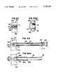
- FIG. 1is a side elevation view of an implant for use with the method of the present invention
- FIG. 2is the view of the implant of FIG. 1 with the implant rotated 90° about its axis;
- FIG. 3is a view taken along line 3--3 of FIG. 1;
- FIG. 4is a view taken along lines 4--4 of FIG. 3;
- FIG. 5is a view taken along lines 5--5 of FIG. 2;
- FIG. 6is a view taken along lines 6--6 of FIG. 3;
- FIG. 7is a cross-sectional side view of an end cap for use with the implant of FIG. 1;
- FIG. 8is a plan view of the implant of FIG. 7;
- FIG. 9is a top plan view of an alignment guide assembly
- FIG. 10is an end plan view of the guide assembly of FIG. 9;
- FIG. 11is a side elevation view of a drill tube guide removal handle
- FIG. 12is a side elevation view of a drill tube guide
- FIG. 13is a side elevation view of a drill tube planar according to the present invention.
- FIG. 13Ais a cross-sectional side view of the planar of FIG. 13;
- FIG. 14is a view taken along line 14--14 of FIG. 13;
- FIG. 15is a side elevation view of a starter vertebral reamer according to the present invention.
- FIG. 16is a proximal end view of the reamer of FIG. 15;
- FIG. 17is an enlarged side elevation view of a reamer head of the starter reamer of FIG. 15;
- FIG. 18is a distal end elevation view of the reamer head of FIG. 17;
- FIG. 19is a side elevation view of an end cap inserter according to the present invention.
- FIG. 20is a distal end view of the inserter of FIG. 19;
- FIG. 21is a side elevation view of a starter alignment guide handle
- FIG. 22is a side elevation view of a drill tube inserter cap
- FIG. 23is a view taken along lines 23--23 of FIG. 22;
- FIG. 24is a distal end view of the inserter cap of FIG. 22;
- FIG. 25is a side elevation view of a distraction plug inserter
- FIG. 26is a side elevation view of a slap hammer
- FIG. 27is a distal end elevation view of the slap hammer of FIG. 26;
- FIG. 28is a side elevation view of a distraction plug for use with the present invention.
- FIG. 29is a side sectional view of a drill tube sleeve according to the present invention.
- FIG. 29Ais a side elevation view of a sheath for use with the present invention.
- FIG. 29Bis a distal end elevation view of the sheath of FIG. 29A;
- FIG. 30is a distal end elevation view of the drill tube sleeve of FIG. 29;
- FIG. 31is a side elevation view of a drill tube for use with the present invention.
- FIG. 32is a view taken along line 32--32 of FIG. 31;
- FIG. 33is an enlarged side elevation view of a distal end of the drill tube of FIG. 31;
- FIG. 34is a side elevation view of a final vertebral reamer
- FIG. 35is an elevation view of a proximal end of the final reamer of FIG. 34;
- FIG. 36is an enlarged view of a reamer head of the reamer of FIG. 34;
- FIG. 37is an end elevation view of a distal end of the reamer head of FIG. 36;
- FIG. 38is a side elevation view of a vertebral reamer guide pin
- FIG. 39is a plan end view of the guide pin of FIG. 38;
- FIG. 40is a side elevation view of a starter tap
- FIG. 41is a view taken along line 41--41 of FIG. 40;
- FIG. 42is an enlarged sectional view of thread cutting teeth of the tool of FIG. 40;
- FIG. 43is a side elevation view of an implant driver for use with the present invention.
- FIG. 44is an end view of a hub on a distal end of the tool of FIG. 43;
- FIG. 45is a view taken along line 45--45 of FIG. 43;
- FIG. 45Ais a side elevation view of a shaft of the tool of FIG. 43 showing an attached collet
- FIG. 45Bis a cross sectional view of FIG. 45A taken along lines 45B--45B;
- FIG. 46is a side elevation exploded view of a vertebral reamer hand driver
- FIG. 47is an end elevation view of the tool of FIG. 46;
- FIG. 48is a side elevation view of two vertebrae separated by a disk
- FIG. 48Ais a view taken along lines 48A--48A of FIG. 48;
- FIGS. 49 and 49Aare views similar to FIGS. 48, 48A showing insertion of a starter alignment guide assembly
- FIGS. 50 and 50Aare views similar to FIGS. 48 and 48A showing placement of a distraction plug by use of an inserter;
- FIGS. 51 and 51Aare views showing the distraction plug in place
- FIGS. 52, 52Aare views similar to the preceding views showing placement of a vertebral reamer guide pin
- FIGS. 53, 53Aare views similar to the foregoing views showing placement and use of a drill tube planar
- FIGS. 54, 54Aare views similar to the foregoing views showing placement of a drill tube
- FIGS. 55, 55Aare views similar to the foregoing showing placement of a drill tube sleeve
- FIGS. 56, 56Aare views similar to the foregoing showing preboring of an implant bore
- FIGS. 57, 57Aare views similar to the foregoing views showing a partially formed bore following the preboring of FIGS. 56, 56A;
- FIGS. 58, 58Aare views similar to the foregoing views showing final boring of an implant bore
- FIGS. 59, 59Aare views similar to the foregoing showing formation of a completed bore after removal of the final boring tool of FIGS. 58, 58A;
- FIGS. 60, 60Aare views similar to the foregoing showing tapping of the bore formed in FIGS. 59, 59A;
- FIGS. 61, 61Aare views similar to the foregoing showing the tapped bore
- FIGS. 62, 62Aare views similar to the foregoing showing placement of an implant within a threaded bore
- FIGS. 63, 63Aare views showing completed placement of an implant within the bore
- FIG. 64is a view showing placement of a drill tube using an end cap inserter.
- FIG. 64Ais a view showing use of a sheath on a drill tube.
- implant 10such as that shown and described in commonly assigned and co-pending U.S. patent application Ser. No. 07/702,351. It will be appreciated that the present surgical procedure can apply to a wide variety of implants including threaded implants such as those shown in the aforementioned U.S. Pat. Nos. 5,015,247 and 4,961,740 as well as non-threaded implants such as shown in U.S. Pat. No. 4,507,269 or other implants.
- implantas used herein may also include bone implants (e.g., autograft, allograft or artificial bone).
- the implant 10(FIGS. 1-6) is a hollow cylinder 12 having male threads 14 exposed on the exterior cylindrical surface of cylinder 12.
- the cylinderincludes a forward interior chamber 16 and a rear interior chamber 17 separated by a reinforcing rib 19, a bone slurry or bone chips may be compacted into chambers 16,17 as will be described.
- a first plurality of holes 18extend radially through the cylinder wall and communicate with the chambers 16,17.
- a second (and enlarged) plurality of holes 21are disposed on diametrically opposed sides of the implant 10.
- a rear end 22 of the implanthas a slot 24 which communicates with the chamber 17.
- the slot 24allows the bone slurry or bone chips to be impacted into the implant 10.
- a slot 25is defined by rib 19.
- the slot 25is sized to receive the distal end of a tool (as will be more fully described) to place the implant within a bore formed between opposing vertebrae.
- An endcap 26(FIGS. 7, 8) is provided to snap fit onto the rear end 12 by means of snap tabs 27.
- the endcap 26is polyethylene or some other radiolucent material to permit post-operative x-ray inspection and determine the adequacy of the fusion after the implant surgery has been performed.
- the technique of the present inventionwill be performed with a prescribed kit of tools.
- the tools of the kitwill now be described. It will be appreciated that the method of the surgery can be practiced using a wide variety of tools of different size and shapes.
- implants 10having minor outside diameters (D m ) of 3 mm, 5 mm, 7 mm, 9 mm, 11 mm, 13 mm, 15 mm, 17 mm, 19 mm and 21 mm with lengths (L) of 10 mm, 12 mm, 14 mm, 16 mm, 16 mm, 20 mm, 24 mm, 28 mm, 28 mm and 30 mm, respectively, are anticipated to accommodate various spine locations and sizes.
- the major outside diameters (D M ) of the implants 10are 2.5 mm larger than the minor outside diameters D m .
- reaming tool 126are sized for particular sizes of implants. Namely, the reaming tool 121 must form a bore sized to receive the implant. Since ten sizes of implants are anticipated, ten sizes of boring tools 126 are anticipated as will become apparent to one of ordinary skill in the art.
- the kit of the present inventionincludes a starter alignment guide handle 28 (see FIG. 21).
- the handleincludes a distal end 30 having an impact flange 31 and an axially extending threaded stud 32.
- a proximal end 34 of the handleis knurled to permit a surgeon to firmly grip the handle 28.
- the starter alignment guide assembly 36(FIGS. 9 and 10) includes a main body 40 having a threaded bore 42 sized to receive the threaded end 32 of handle 28. Extending from the body 40 are parallel pins 44, 46. The pins are spaced apart by a distance D 1 as will be more fully described. The pins 44, 46 have stop surface 45, 47.
- kitwill require various sizes of tools.
- starter alignment guide assembly 36it is anticipated that at least ten tools will be provided having pin spacings D 1 selected to identify a desired spacing of two implants each of diameters of 3, 5, 7, 9, 11, 13, 15, 17, 19, and 21 mm, respectively.
- pin spacings D 1selected to identify a desired spacing of two implants each of diameters of 3, 5, 7, 9, 11, 13, 15, 17, 19, and 21 mm, respectively.
- such a kitwill only require one guide handle 28 which can be inserted and attached to each of the starter alignment guide assemblies 36.
- the main body 40is nylon to be X-ray transparent. Also, the body 40 has curved edges 49 with a radius of curvature to match a radius of a corresponding drill tube 92. For example, for placing two 13 mm (D m ) implants 10, a drill tube 92 with an inside diameter of 16.0 mm (for a D M of 15.5) is required (the 0.5 mm difference providing clearance). The edges 49 match the contour of the drill tube 92 and are spaced apart equal to a spacing of the drill tube when operating on either the right or left side. As a result, the back surface 43 of main body 40 may be placed against the spine to outline an area which must be cleared for the procedure. This aids the surgeon in determining the proper laminectomy size or required amount of vessel retraction.
- a distraction plug inserter 48(FIG. 25) is provided and includes a shaft 50 and a handle end 51 which is knurled to provide a secure grip.
- a distal end 53has a threaded shaft 52 extending axially therefrom.
- End 51has a larger diameter than shaft 50 to provide a surface 49 against which slap hammer 192 (FIG. 26) may strike as will become apparent.
- a distraction plug 54(FIG. 28) is provided having a generally cylindrical body 56 with a tapered forward end 58.
- the rear endhas a reduced diameter portion 55 terminating at a flange 57 having a diameter the same as the body 56.
- a threaded bore 62is formed through the rear end to receive the threaded shaft 52 of the distraction plug inserter 48.
- the body 56is knurled to prevent undesired axial movement of the plug 54 after it is inserted.
- the distraction plug 54is used to initially distract opposing vertebrae.
- the amount of desired distractionwill vary from patient to patient and from spine location to spine location. Accordingly, it is anticipated that distraction plugs having diameters D 2 ranging from 3 to 14 mm (by one millimeter increments) shall be included within the kit.
- Each of the distraction plugsfits on the inserter 48 such that only one inserter 48 is required for the kit.
- a vertebral reamer guide pin 64(FIGS. 38 and 39) is provided including a generally cylindrical body 66 having a tapered forward end 68 and a reduced diameter threaded rear end 70.
- the tapered forward end 68has three flats 69 that grind away disc material when the pin 64 is secured to a starter reamer 112 (FIG. 15) as will be described.
- guide pins 64are anticipated to be required in the kit having diameters D 3 ranging from 3 through 14 mm (increasing by one millimeter increments). For reasons that will become apparent, it is desired that all of the guide pins 64 have a threaded stud 70 of identical size.
- a drill tube guide 72(FIG. 12) is provided including a cylindrical shaft 74 and a distal end 76.
- the distal end 76has a predetermined maximum outside diameter D 4 .
- a bore 80which is threaded and sized to receive stud 70 of the guide pin 64.
- a proximal end 82 (of diameter D 4 ) of the drill tube guidehas a threaded bore 81 for purposes that will be described. End 82 terminates at a flat axial face 83.
- kits of the present inventionwill include ten drill tube guides having outside diameters D 4 to finally prepare bores to receive the three sizes of implants as will be described.
- the outside diameters D 4are equal to D M for each matching pair of implant 10 and drill tube guide 72.
- tissuemay cover the surface of the vertebrae to be bored.
- the various tools of the present inventionshould abut vertebrae bone to insure that an implant 10 is inserted to a proper depth.
- a drill tube planar 84removes the tissue and provides a flat surface on the vertebrae bone against which to place tools.
- the drill tube planar 84(FIGS. 13 and 14) includes a hollow tube 86 having an inside diameter D 5 .
- the distal end 88 of the drill tube planar 84includes a toothed rasp surface 85 to rasp away bone material as the distal end 88 is placed against bone and the planar 84 is rotated about its axis.
- the proximal end 90 of the planar 84includes a knurled handle to permit a surgeon to securely grasp the planar during the planing operation.
- the planar 84will slip over the drill tube guide 72 with the diameter D 4 selected in close tolerance to D 5 (i.e., D 5 is 0.5 mm larger than D 4 ).
- D 5is 0.5 mm larger than D 4 .
- ten planars 84are required to fit on the ten sizes of drill tube guides 72.
- the planar 84includes an internal stop 87 positioned to oppose surface 83 of guide 72 when the planar 84 is placed over guide 72.
- a clean out hole 89is provided to clean out planar 84.
- a drill tube 92(FIGS. 31, 32, and 33) is provided in the form of a hollow cylindrical tube 94.
- the distal end 96 of the tube 94is provided axially projecting teeth 98.
- the proximal end 99 of the tube 94is flared outwardly for purposes that will become apparent.
- ten sizes of tube 92are required with inside diameters D 6 to slip in close tolerance over ten sizes of drill tube guide 72 (i.e., D 6 is 0.5 mm larger than D 4 ).
- the teeth 98each have a length, T L , of preferably 3 mm.
- the valleys 97are flat to provide stop surfaces to hit bone as teeth 98 are forced into vertebrae. This helps prevent the drill tube 92 from being forced too far into bone.
- the drill tube 92is secured to vertebrae by forcing the teeth 98 into the vertebrae bone material. This is done by impacting the proximal end 99 of the drill tube 92.
- An inserter cap 100(FIGS. 22, 23 and 24) is provided in the form of a solid cylinder having an axial bore 102 with an inside diameter D 9 terminating at a flat annular face 101. Diameter D 9 is slightly larger than outside diameter D 4 of drill tube guide 72 (FIG. 12) so that cap 100 can slip over end 82 of guide 72 with a stop surface 103 opposing end 83 and with surface 101 opposing flared end 99 of drill tube 92.
- the cap 100has an opposite flat end 104 against which a surgeon may impact. This impacts the drill tube 92 to force the teeth 98 into the bone of a vertebrae.
- a drill tube sleeve 105(FIGS. 29 and 30) is provided in the form of a hollow tube having a flat distal end and an outwardly flared proximal end 110.
- Ten sizes of sleeves 105are required in the kit having outside diameters D 7 sized to slip within, in close tolerance, the ten sizes of drill tubes 92.
- the inside diameter D 10is selected to be slightly greater (e.g., 0.5 mm larger) than the minor outside diameter D m of the implants 10.
- a starter vertebral reamer 112is provided (FIGS. 15 through 18).
- the starter reamer 112has a shaft 114.
- a reamer head 116is secured to the distal end of the shaft 114.
- An axial face of the reamer 116has a threaded bore 118 sized to receive the threaded shaft 70 of the vertebral reamer guide pin 64.
- a proximal end 120has an outwardly flared hub 122 to act as a positive stop against flare 110 of the drill tube sleeve 106 as will be more fully described.
- a shaft 124extends from the distal end.
- the reamer 116includes cutting blades 117 that provide both end cutting and side cutting into bone as the starter reamer 112 is rotated about its axis.
- the reamers 112have outside diameters D 11 equal to the minor outside diameters D m of the implants 10.
- a final vertebral reamer 126(FIGS. 34 through 37), is provided for completing a bore started by the starter vertebral reamer 112.
- the final reamer 126includes a shaft 128.
- a distal end of the shaftis provided with a reamer end 130 having side and end cutting blades 131.
- a proximal end of the shaftis provided with an outwardly flared hub 132. Extending from hub 132 is an axial shaft 134.
- the outside diameter D 12 of final reamer 126equals the minor outside diameter D m of implants 10.
- a hand driver 136(FIGS. 46 and 47) is provided.
- the hand driverincludes an axial bore 138 to receive either of shafts 124 or 134.
- the hand driver 136also includes a manually engageable handle 140 to be actuated by a surgeon performing the surgery of the present invention.
- the handlehas an enlarged barrel portion 137 with radial grooves 139.
- a surgeonputs axial pressure on handle 140 and with the other hand the surgeon rotates barrel 137 with fingers in grooves 139.
- the surgeoncan securely turn a reamer secured to the driver 136.
- Radial bores 141,143extend through barrel 137 to receive set screws to fix a shaft 124 or 134 received within bore 138.
- a bone tap 142(FIGS. 40 through 42) is provided, having a shaft 144. At the distal end of the shaft 144 is a tapping head 146 having tapping threads 148. Near the proximal end of the shaft 144 is an enlarged diameter portion 156 having an outwardly flared flange 158. A handle 160 is secured to the enlarged portion 156.
- the shaft 144is also enlarged at portion 162 adjacent tapping head 146.
- the enlarged portion 156is sized with diameter D 8 to be received, in close tolerance, within the drill tube 92 such that the tube 92 will guide the tap 142 as will be more fully described.
- Diameter D 8is equal to the major outside diameter D M of implant 10.
- the head 146has a minor outside diameter D 13 (i.e., the diameter without threads 148) equal to the minor outside diameter D m of the implants 10.
- an implant driver 164(FIGS. 43 through 45) is provided.
- the driver 164includes a shaft 166 having a reduced diameter distal portion 166a.
- a distal end of the shaft 166is provided with a hub 168 sized to be received within slot 24 of the implant 10 to urge the implant 10 to rotate as the implant driver 164 is rotated.
- the implant driver 164includes a stepped enlarged portion 170 including a first diameter portion 172, a second diameter portion 174 and a third diameter portion 176 to accommodate the different diameters of drill tubes 92.
- a handle 178is secured to the shaft 164.
- Grooves 180, 180aare formed on the shafts 166, 166a and extend along their axial lengths. The grooves 180 provide a means for a surgeon to sight the alignment of the implant.
- FIGS. 45A and 45Bshow the implant driver 164 with a collet 171.
- the collet 171has a cylindrical, knurled body 173 slidably carried on shaft 166a.
- a pin 175 extending from body 173 into groove 180apermits collet 171 to slide on shaft 166 but not rotate.
- Four prongs 177extend axially from body 173 toward hub 168.
- shaft 166is passed through end opening 24 of implant 10.
- Hub 168is receiving within slot 25.
- the prongs 177are forced by a surgeon pushing on body 171 for the prongs 177 to be urged between opposing surfaces of the implant 10 and shaft 166a to thereby securely capture the implant 10 on driver 164. As a result, the implant 10 cannot inadvertently fall off. (For ease of illustration, the Figures showing the method of the invention, FIGS. 48-63A, do not show use of collet 171).
- an endcap inserter 180(FIGS. 19 and 20) is provided.
- the inserter 180includes a shaft 182. At the distal end of the shaft, a head 184 is provided having a cupped surface 186 to receive and temporarily hold an endcap 26 before it is secured in place.
- An enlarged portion 180 of the shaftis sized to be received, in close tolerance, within drill tube 92 to be guided by the tube 92. Since ten sizes of drill tubes are required for ten sizes of implants, ten sizes of endcap inserters are also required.
- the inserter 180has an outside diameter D 14 just smaller than (e.g., 0.5 mm smaller) than the inside diameter D 6 of the drill tube 92.
- a knurled handle 190is provided on the proximal end of the shaft 182.
- a slap hammer 192(FIGS. 26 and 27) is provided.
- the slap hammeris a cylindrical body having a knurled surface to permit a surgeon to securely grip the body.
- the hammerhas an axial slot 196.
- the hammeris placed on the shafts 202, 50 of handle 200 or inserter 48, respectively, with the tool shaft received within slot 196.
- a stop surfacee.g., surface 49 of tool 48
- a handle 200(FIG. 11) is provided to remove the drill tube guide 72.
- the handle 200includes a shaft 202.
- a threaded stub 204is provided sized to be threadably received within the threaded bore 81 of the drill tube guide 72.
- a proximal end of the handle 200is provided with an enlarged diameter knurled handle 206 to permit a surgeon to securely grasp the handle 200 and to stop the travel of slap hammer 192.
- drill tube 92 or planar 84are passed through a patient's body to an implant site.
- a drill tube sheath 300is provided (FIGS. 29A, 29B).
- the sheath 300is a hollow tube with inside diameter D 15 slightly smaller than the outside diameter of drill tubes 92 or planars 84 (accordingly ten sizes of sheath 300 are required).
- the sheath 300has an axial slit 301 extending its entire length.
- the sheath 300has a blunt distal end 302 and a flared proximal end 304.
- the sheathis slipped onto the drill tube 92 or planar 84 with end 302 extending beyond the teeth 85 or 98 (see FIG. 64A illustrating use of sheath 300 with drill tube 92).
- the blunt end 302covers the teeth and prevents the unwanted cutting of vessels, nerves or organs.
- the end 302abuts the vertebrae.
- the sheath 300slides on the planar 84 or tube 92 until teeth 85,98 abut the vertebrae.
- sheath 300remains in place whenever planar 84 or drill tube 92 are used. However, for ease of illustration, sheath 300 is not shown in FIGS. 46-63A.
- the present inventionwill first be described with reference to use in a posterior approach.
- a posterior approacha surgeon seeks access to the spine through the back of the patient.
- An alternative approachis an anterior approach where the surgeon seeks access to the spine through the abdomen of a patient.
- the anterior approachcan be done through open surgery or through laparoscopic surgery.
- the surgeonidentifies an implant of desired size and the surgeon determines the desired amount of distraction to be required between the vertebrae before placement of the implant.
- the surgeonshould ensure that the device will remain within the lateral borders of the intervertebral disc while also penetrating at least 3 mm into the vertebral bodies cephalad and caudal to the disc.
- a patientis placed on the operating table in either a prone or kneeling-sitting position. At the discretion of the surgeon, the spine is flexed slightly. Anesthesia is administered.
- Exposure of the intervertebral discis obtained through any suitable technique well-known in the art.
- the facet of the vertebraeis removed in as limited amount as possible to permit insertion of the instruments and the implants.
- Preferably, bone dissected from the lamina, facets and spinous processare preserved for later use as bone graft.
- FIG. 48two vertebrae 210, 212 are separated by a disc 214.
- the disc 214is shown in plan view in FIG. 48A. As shown in the figures, no procedure has yet been performed on the disc such that the disc 214 is in a relaxed, undistracted state.
- the surgeonselects the starter alignment guide assembly 36 and secures the handle 28 to the assembly 36 by threading shaft 32 into bore 42.
- the prongs 44, 46 of the guide 36are placed on either side of the cauda equina such that they are at mid-disc height and equidistant from the midsagittal plane.
- the guideis pressed ventrally to make two points 44a, 46a on the disc for implant insertion as shown in FIGS. 49, 49A.
- the two points 44a, 46amark right and left side desired implant location points.
- right and leftwill mean with respect to the view of the back of the spine as viewed by the surgeon performing the surgery through the posterior approach.
- the handle 28is unscrewed and removed from the guide 36. Lateral and anterior-posterior x-rays or C-arm fluoroscopy are taken of the alignment guide 36 to verify its orientation within the disc space. If the alignment guide 36 is determined to be correctly positioned, it is removed from the disc space by reattaching handle 28 and pulling the guide 36 out. A limited discectomy is performed through the two openings 44a, 46a in the disc to permit insertion of a distraction plug 54.
- the surgeonselects a side (i.e., left or right) in which to initiate the distraction procedure.
- a sidei.e., left or right
- the distraction plug inserter 48is secured to a distraction plug 54 by threading end 52 into bore 62.
- the distraction plug 54is forced into the disc space at the indent 46a made at the left side of the vertebrae by the prong 46 (see FIGS. 50 and 50A).
- the size of distraction plug 54is selected to distract the annulus fibrosus without causing damage to the surrounding vertebral bone, annular fibers or spinal nerves.
- the surgeoninitially insert a relatively small plug 54 (for example, 8 mm) followed by successively larger plugs until the annulus is distracted to the surgeon's satisfaction.
- a relatively small plug 54for example, 8 mm
- the handle 48removed as shown in FIGS. 51 and 51A.
- the disc 214has now been stretched so that a parallel distraction of the opposing end plates 210',212' of the vertebrae 210,212 has occurred on both the left and right sides.
- the distraction plug 54is fully inserted such that it is either flush or slightly recessed within the disc space.
- the surgeontakes care to retract the cauda equina and nerve roots from the area being prepared for the drill tube 92 as will be described.
- the distraction plug 54is placed recessed.
- the caudacan be moved over into the region of the distractor plug 54 without the distractor plug 54 damaging the cauda equina.
- the vertebral reamer guide pin 64is secured to the drill tube guide 72 by threading the shaft 70 within the bore 80.
- the guide pin 64 selectedis preferably the same diameter as the final distraction plug 54 left in place within the disc space on the left side.
- the guide pin 64abuts the opposing end plates 210',212' of the vertebrae 210,212 as does plug 54.
- the axis of pin 64is equidistant from the end plates 210',212'.
- the surface of the vertebrae 210, 212 against which tools are to be placedshould be smooth with the surface of the two vertebrae 210, 212 aligned. Frequently, this condition will not naturally exist. Therefore, the vertebrae 210, 212 must be pre-planed to a flat surface.
- the drill tube planar 84is passed over the drill tube guide 72 with the rasp end 88 abutting the disc material 214 and vertebrae 210, 212 or tissue (not shown) on the vertebrae as shown in FIG. 53, 53A.
- the interior diameter of the planar 84is selected to have a close tolerance with the exterior diameter of the drill tube guide 72.
- the planar 84can rotate on the drill tube guide 72 and move axially relative thereto but cannot move laterally relative to the tube guide 72.
- the surgeonrotates the planar 84 to rasp a planed flat surface on the vertebrae.
- the raspingwill provide a smooth surface for placing of the drill tube as will be described.
- the rasp end 88is shown deeply received with the vertebrae after rasping.
- the drill tube guide 72prevents planar 84 from excessive axially movement. Namely, when planar 84 is fully advanced, surface 87 abuts surface 83 signalling completion of the rasping operation.
- the planar 84is removed and the appropriately sized drill tube 92 is passed over the drill tube guide 72 (see FIGS. 54, 54A).
- the teeth 98 of the drill tube 92are secured to the posterior vertebral bodies using the drill tube inserter cap 100 to pound the teeth 98 into the vertebral bodies 210, 212.
- the drill tube guide 72 and the vertebral reamer guide plug 64are then removed from the drill tube 92 leaving the drill tube 92 in place and with the teeth 98 thereby retaining the vertebral bodies in the distracted state.
- handle 18is attached to guide 72 by threading stud 204 into bore 84. The surgeon uses the slap hammer 192 to remove the guide and handle assembly.
- FIG. 64illustrates use of the cap 100 to advance teeth 98 into the vertebrae 210,212.
- the drill tube guide 72is longer than drill tube 92. With teeth 98 aligned with end 78, end 83 protrudes beyond flange 99.
- the cap 100is positioned as shown in FIG. 22A.
- the capis sized for the distance, X, between surfaces 83,103 to be about 3 mm when teeth 98 are flush with end 78. Pounding on surface 104, teeth 98 are driven in 3 mm until surface 103 stops against surface 83.
- the flats 97 of the teeth 98prevent further advancement of the drill tube 92 into the bone.
- the drill tube 92has an inside diameter approximate to the outside diameter of the drill tube guide 72. Accordingly, the drill tube guide 72 accurately places the drill tube 92 in proper alignment. In this alignment, the tube 92 has its axis equidistant from the end plates 210',212' of vertebrae 210,212. Since all insertion tools and tubes of the kit have lengths sized off of the drill tube guide 72, the guide 72 insures that a final desired depth of implant penetration is attained.
- a drill tube sleeve 106is placed in the drill tube with the top end 110 abutting the top end 99 of the drill tube 92. As shown in FIGS. 55, 55A, when the sleeve is fully inserted, its flared end 110 abuts the flared end of the drill tube.
- the vertebral reamer guide pin 64is then threaded on to the starter vertebral reamer 112.
- the guide pin 64 usedis the same pin 64 previously used on the drill tube guide 72.
- the cavity 65(FIG. 55) left after removal of the pin 64 (described in step G, above) receives the pin 64/reamer 112 assembly to guide the reamer 112 such that the reamer 112 cuts equal amounts of bone from both vertebrae 210,212.
- the starter vertebral reamer 112is inserted into the drill tube sleeve 106 and then a bore is partially reamed until a shoulder 122 on the reamer 112 abuts the drill tube sleeve 106 as shown in FIGS. 56, 56A.
- the hand driver 136(FIG. 46) is used to turn reamer 112. However, for ease of illustration, the driver 136 is not shown in FIGS. 56, 56A.
- the reamer 112 and the drill tube sleeve 106are then removed from the drill tube 92 (see FIGS. 57, 57A) exposing a pre-drilled bore 200 with a diameter equal to the minor outside diameter D m of implant 10.
- the preparation of the implant boreis then completed by inserting the final vertebral reamer 126 into the drill tube 92 (FIGS. 58, 58A).
- the reamer 126is rotated with driver 136 (not shown in FIG. 46) until the shoulder 132 on the reamer 126 meets the flared end of the drill tube 92 to thereby provide a positive stop.
- the readerwill note that the lengths of the various drill tubes, drill tube sleeves and reamers are selected such that the flared ends provide accurate depth of reaming between the vertebral bodies. Also, the reader will note that both vertebrae 210, 212 are equally drilled. Additionally, the reader will note the pre-boring of step H, above, ensures the final bore 220 is cut parallel to end plates 210',212' and equally cut into both vertebrae 210,212.
- a bone tap 142is passed through the drill tube 92 and rotated to partially pre-tap the bore 210. The tap is introduced until the stop 158 on the handle abuts the top of the drill tube 92 as shown in FIGS. 60, 60A.
- the tapis then removed to expose a partially tapped, fully bored implant bore 300 with the drill tube 92 remaining in place (see FIGS. 61 and 61A).
- the front chamber 16 of the implant 10is packed with bone graft.
- the graftmay be autograft obtained previously from the iliac crest or some other graft material (e.g., allograft or artificial bone).
- the implant 10is attached to the implant driver 164 by placing the hub 188 within the slot 24 and securing the implant with collet 171 (not shown in FIGS. 62, 62A).
- the implant 10is then passed into the drill tube 92 (FIGS. 62, 62A).
- the implant 10is threaded into the bore 300 with implant driver 168 by the surgeon rotating the driver 168 and advancing it into the tube 92 until the driver stop 176 contacts the top of the drill tube 92.
- the large holes 211 of the implantare oriented in a superior-inferior direction (i.e., the large holes are facing the vertebrae). This orientation is guaranteed by orienting the slots 180 in the implant driver 168 to be vertical.
- the implant driver 168 and the drill tube 92are removed from the right-side hole (see FIGS. 63 and 63A). Simply pulling on driver 164 releases the implant 10 from the collet 171.
- the surgeonobtain a lateral radiograph or C-arm fluoroscopy to verify the positioning of the implant 10 within the intervertebral space. If proper positioning has been obtained, the back chamber 17 of the implant 10 is packed with bone graft.
- the drill tube 92may be left in place with the graft inserted to chamber 17 through tube 92. If removed, tube 92 is repositioned after chamber 17 is filled.
- the polyethylene endcap 26is attached to the end of the implant 10 with the endcap inserter 180 by passing the endcap through the drill tube 92.
- the right side implantis fully inserted.
- the surgeonreturns to the left side and removes the distraction plug 54 by threading the handle 48 into the distraction plug 54 and pulling it out using slap hammer 192. If, for any reason, the threaded stud 52 on handle 48 were to break, the reduced diameter portion 55 of plug 54 permits a surgeon to pull on flange 57 to remove plug 54.
- the left sideis now prepared for receiving an implant in a manner identical to that described above for the right disc space with the procedures identified in FIGS. 52 through 63A.
- the foregoing procedureillustrates the method of the present invention with respect to a posterior approach.
- the identical procedurecan be used with an anterior approach.
- the present procedureis readily adaptable to a laparoscopic approach. Through placement of a cannula (not shown) in a laparoscopic approach, all the procedures can be performed through the cannula with the various tubes and sleeves described above passed through the cannula and accurately placed.
- All of the foregoing tools of the kit of the inventioncan be passed through a cannula except for alignment guide assembly 36.
- the implant sitescan be marked through any other suitable technique or a collapsible alignment guide assembly can be provided to pass through a cannula.
- the method and tools of the inventioncan be used with a single implant (either a threaded implant 10, a non-threaded implant or a bone or any other implant).
- the plug 54is inserted at a desired site.
- the plug 54is then removed and the pin 64 inserted into the same site using the guide 72. All procedures described above are then used to form an implant receiving bore.
Landscapes
- Health & Medical Sciences (AREA)
- Engineering & Computer Science (AREA)
- Biomedical Technology (AREA)
- Orthopedic Medicine & Surgery (AREA)
- Life Sciences & Earth Sciences (AREA)
- General Health & Medical Sciences (AREA)
- Public Health (AREA)
- Transplantation (AREA)
- Heart & Thoracic Surgery (AREA)
- Veterinary Medicine (AREA)
- Oral & Maxillofacial Surgery (AREA)
- Animal Behavior & Ethology (AREA)
- Cardiology (AREA)
- Neurology (AREA)
- Vascular Medicine (AREA)
- Surgery (AREA)
- Dentistry (AREA)
- Nuclear Medicine, Radiotherapy & Molecular Imaging (AREA)
- Medical Informatics (AREA)
- Molecular Biology (AREA)
- Physical Education & Sports Medicine (AREA)
- Surgical Instruments (AREA)
- Prostheses (AREA)
- Heterocyclic Carbon Compounds Containing A Hetero Ring Having Nitrogen And Oxygen As The Only Ring Hetero Atoms (AREA)
- Control And Other Processes For Unpacking Of Materials (AREA)
Abstract
Description
Claims (6)
Priority Applications (6)
| Application Number | Priority Date | Filing Date | Title |
|---|---|---|---|
| US08/482,025US5720748A (en) | 1993-02-10 | 1995-06-07 | Spinal stabilization surgical apparatus |
| US08/752,818US5947971A (en) | 1993-02-10 | 1996-11-21 | Spinal stabilization surgical apparatus |
| US08/901,950US5899908A (en) | 1993-02-10 | 1997-07-29 | Spinal drill tube guide |
| US09/369,614US6599320B1 (en) | 1993-02-10 | 1999-08-06 | Alignment guide assembly for spinal stabilization |
| US10/627,589US7135026B2 (en) | 1993-02-10 | 2003-07-25 | Laparoscopic spinal stabilization surgical method |
| US11/458,426US7722621B2 (en) | 1993-02-10 | 2006-07-19 | Laparoscopic spinal stabilization surgical method |
Applications Claiming Priority (3)
| Application Number | Priority Date | Filing Date | Title |
|---|---|---|---|
| US1586393A | 1993-02-10 | 1993-02-10 | |
| US08/299,807US5489307A (en) | 1993-02-10 | 1994-09-01 | Spinal stabilization surgical method |
| US08/482,025US5720748A (en) | 1993-02-10 | 1995-06-07 | Spinal stabilization surgical apparatus |
Related Parent Applications (1)
| Application Number | Title | Priority Date | Filing Date |
|---|---|---|---|
| US08/299,807DivisionUS5489307A (en) | 1993-02-10 | 1994-09-01 | Spinal stabilization surgical method |
Related Child Applications (1)
| Application Number | Title | Priority Date | Filing Date |
|---|---|---|---|
| US08/752,818ContinuationUS5947971A (en) | 1993-02-10 | 1996-11-21 | Spinal stabilization surgical apparatus |
Publications (1)
| Publication Number | Publication Date |
|---|---|
| US5720748Atrue US5720748A (en) | 1998-02-24 |
Family
ID=21774064
Family Applications (10)
| Application Number | Title | Priority Date | Filing Date |
|---|---|---|---|
| US08/299,807CeasedUS5489307A (en) | 1993-02-10 | 1994-09-01 | Spinal stabilization surgical method |
| US08/488,375Expired - LifetimeUS5700291A (en) | 1993-02-10 | 1995-06-07 | Laparoscopic spinal stabilization method |
| US08/482,025Expired - LifetimeUS5720748A (en) | 1993-02-10 | 1995-06-07 | Spinal stabilization surgical apparatus |
| US08/752,818Expired - LifetimeUS5947971A (en) | 1993-02-10 | 1996-11-21 | Spinal stabilization surgical apparatus |
| US08/891,276Expired - LifetimeUS5928242A (en) | 1993-02-10 | 1997-07-10 | Laparoscopic spinal stabilization method |
| US08/901,950Expired - LifetimeUS5899908A (en) | 1993-02-10 | 1997-07-29 | Spinal drill tube guide |
| US09/369,614Expired - Fee RelatedUS6599320B1 (en) | 1993-02-10 | 1999-08-06 | Alignment guide assembly for spinal stabilization |
| US09/971,307Expired - LifetimeUSRE42863E1 (en) | 1993-02-10 | 2001-10-04 | Spinal stabilization surgical method |
| US10/627,589Expired - Fee RelatedUS7135026B2 (en) | 1993-02-10 | 2003-07-25 | Laparoscopic spinal stabilization surgical method |
| US11/458,426Expired - Fee RelatedUS7722621B2 (en) | 1993-02-10 | 2006-07-19 | Laparoscopic spinal stabilization surgical method |
Family Applications Before (2)
| Application Number | Title | Priority Date | Filing Date |
|---|---|---|---|
| US08/299,807CeasedUS5489307A (en) | 1993-02-10 | 1994-09-01 | Spinal stabilization surgical method |
| US08/488,375Expired - LifetimeUS5700291A (en) | 1993-02-10 | 1995-06-07 | Laparoscopic spinal stabilization method |
Family Applications After (7)
| Application Number | Title | Priority Date | Filing Date |
|---|---|---|---|
| US08/752,818Expired - LifetimeUS5947971A (en) | 1993-02-10 | 1996-11-21 | Spinal stabilization surgical apparatus |
| US08/891,276Expired - LifetimeUS5928242A (en) | 1993-02-10 | 1997-07-10 | Laparoscopic spinal stabilization method |
| US08/901,950Expired - LifetimeUS5899908A (en) | 1993-02-10 | 1997-07-29 | Spinal drill tube guide |
| US09/369,614Expired - Fee RelatedUS6599320B1 (en) | 1993-02-10 | 1999-08-06 | Alignment guide assembly for spinal stabilization |
| US09/971,307Expired - LifetimeUSRE42863E1 (en) | 1993-02-10 | 2001-10-04 | Spinal stabilization surgical method |
| US10/627,589Expired - Fee RelatedUS7135026B2 (en) | 1993-02-10 | 2003-07-25 | Laparoscopic spinal stabilization surgical method |
| US11/458,426Expired - Fee RelatedUS7722621B2 (en) | 1993-02-10 | 2006-07-19 | Laparoscopic spinal stabilization surgical method |
Country Status (9)
| Country | Link |
|---|---|
| US (10) | US5489307A (en) |
| EP (1) | EP0683651B1 (en) |
| JP (1) | JP3695755B2 (en) |
| AT (1) | ATE185062T1 (en) |
| AU (2) | AU683243B2 (en) |
| CA (1) | CA2155422C (en) |
| DE (1) | DE69420947T2 (en) |
| ES (1) | ES2141217T3 (en) |
| WO (1) | WO1994017759A1 (en) |
Cited By (150)
| Publication number | Priority date | Publication date | Assignee | Title |
|---|---|---|---|---|
| US5928243A (en) | 1997-07-16 | 1999-07-27 | Spinal Concepts, Inc. | Pedicle probe and depth gage |
| US5928239A (en)* | 1998-03-16 | 1999-07-27 | University Of Washington | Percutaneous surgical cavitation device and method |
| US5935133A (en) | 1997-08-26 | 1999-08-10 | Spinal Concepts, Inc. | Surgical cable system and method |
| US5989250A (en) | 1996-10-24 | 1999-11-23 | Spinal Concepts, Inc. | Method and apparatus for spinal fixation |
| US6007496A (en)* | 1996-12-30 | 1999-12-28 | Brannon; James K. | Syringe assembly for harvesting bone |
| US6030389A (en) | 1997-08-04 | 2000-02-29 | Spinal Concepts, Inc. | System and method for stabilizing the human spine with a bone plate |
| US6045579A (en) | 1997-05-01 | 2000-04-04 | Spinal Concepts, Inc. | Adjustable height fusion device |
| US6053921A (en) | 1997-08-26 | 2000-04-25 | Spinal Concepts, Inc. | Surgical cable system and method |
| US6059790A (en)* | 1997-08-29 | 2000-05-09 | Sulzer Spine-Tech Inc. | Apparatus and method for spinal stabilization |
| US6074423A (en)* | 1998-11-02 | 2000-06-13 | Lawson; Kevin Jon | Safer more X-ray transparent spinal implant |
| US6126660A (en)* | 1998-07-29 | 2000-10-03 | Sofamor Danek Holdings, Inc. | Spinal compression and distraction devices and surgical methods |
| US6132430A (en) | 1996-10-24 | 2000-10-17 | Spinal Concepts, Inc. | Spinal fixation system |
| US6171339B1 (en) | 1998-05-19 | 2001-01-09 | Sulzer Spine-Tech Inc. | Multi-lumen spinal implant guide and method |
| US6251140B1 (en) | 1998-05-27 | 2001-06-26 | Nuvasive, Inc. | Interlocking spinal inserts |
| US6290724B1 (en) | 1998-05-27 | 2001-09-18 | Nuvasive, Inc. | Methods for separating and stabilizing adjacent vertebrae |
| US6325827B1 (en) | 1999-02-01 | 2001-12-04 | Blacksheep Technologies, Inc. | Intervertebral implant |
| US6368325B1 (en) | 1998-05-27 | 2002-04-09 | Nuvasive, Inc. | Bone blocks and methods for inserting bone blocks into intervertebral spaces |
| US6371986B1 (en) | 1998-10-27 | 2002-04-16 | George W. Bagby | Spinal fusion device, bone joining implant, and vertebral fusion implant |
| US20020058939A1 (en)* | 1997-08-04 | 2002-05-16 | Spinal Concepts, Inc. | System and method for stabilizing the human spine with a bone plate |
| WO2002056802A1 (en) | 2000-12-15 | 2002-07-25 | Spineology, Inc. | Annulus-reinforcing band |
| US20020107573A1 (en)* | 1999-03-07 | 2002-08-08 | Discure Ltd. | Method and apparatus for computerized surgery |
| US6436141B2 (en) | 2000-04-07 | 2002-08-20 | Surgical Dynamics, Inc. | Apparatus for fusing adjacent bone structures |
| US6447545B1 (en) | 2000-07-01 | 2002-09-10 | George W. Bagby | Self-aligning bone implant |
| US6447512B1 (en) | 2000-01-06 | 2002-09-10 | Spinal Concepts, Inc. | Instrument and method for implanting an interbody fusion device |
| US20020128715A1 (en)* | 2000-08-08 | 2002-09-12 | Vincent Bryan | Implantable joint prosthesis |
| US20020138147A1 (en)* | 2001-03-22 | 2002-09-26 | Surgical Dynamics, Inc. | Apparatus for fusing adjacent bone structures |
| US20020143400A1 (en)* | 1999-02-25 | 2002-10-03 | Depuy Acromed, Inc. | Spinal fusion implant |
| US6533791B1 (en)* | 1997-11-13 | 2003-03-18 | Sulzer Orthopedics Ltd. | Instrument system for the operative correction of vertebral displacements |
| US6540753B2 (en) | 2001-03-23 | 2003-04-01 | Howmedica Osteonics Corp. | Instrumentation for implant insertion |
| US6557226B1 (en) | 1999-04-23 | 2003-05-06 | Michael E. Landry | Apparatus for manufacturing a bone dowel |
| US6562041B1 (en) | 1997-08-29 | 2003-05-13 | Sulzer Spine-Tech Inc. | Apparatus and method for spinal stabilization |
| US6562045B2 (en) | 2001-02-13 | 2003-05-13 | Sdgi Holdings, Inc. | Machining apparatus |
| US20030097181A1 (en)* | 1999-04-07 | 2003-05-22 | Salvatore Castro | Low profile fusion cage and insertion set |
| US6575981B1 (en) | 1999-02-04 | 2003-06-10 | Sdgi Holdings, Inc. | Methods and instrumentation for vertebral interbody fusion |
| US6575899B1 (en) | 1999-10-20 | 2003-06-10 | Sdgi Holdings, Inc. | Methods and instruments for endoscopic interbody surgical techniques |
| US6582437B2 (en) | 1999-08-26 | 2003-06-24 | Sdgi Holdings, Inc. | Devices and methods for implanting fusion cages |
| US20030135277A1 (en)* | 2001-11-26 | 2003-07-17 | Sdgi Holdings, Inc. | Implantable joint prosthesis and associated instrumentation |
| US6599291B1 (en) | 2000-10-20 | 2003-07-29 | Sdgi Holdings, Inc. | Methods and instruments for interbody surgical techniques |
| US6635086B2 (en) | 2000-05-30 | 2003-10-21 | Blacksheep Technologies Incorporated | Implant for placement between cervical vertebrae |
| US20030199982A1 (en)* | 1998-09-04 | 2003-10-23 | Sdgi Holdings, Inc. | Peanut spectacle multi discoid thoraco-lumbar disc prosthesis |
| US20030199738A1 (en)* | 2000-08-08 | 2003-10-23 | Sdgi Holdings,Inc. | Clamping apparatus and methods |
| US6648895B2 (en) | 2000-02-04 | 2003-11-18 | Sdgi Holdings, Inc. | Methods and instrumentation for vertebral interbody fusion |
| US6656190B2 (en)* | 2000-03-15 | 2003-12-02 | Spinevision S. A. | Implant prehension device |
| US6682534B2 (en) | 2001-08-02 | 2004-01-27 | Depuy Acromed, Inc. | Endplate preparation instrument and associated method |
| US20040054411A1 (en)* | 2000-08-08 | 2004-03-18 | Sdgi Holdings, Inc. | Wear-resistant endoprosthetic devices |
| US20040083002A1 (en)* | 2001-04-06 | 2004-04-29 | Belef William Martin | Methods for treating spinal discs |
| US6736815B2 (en) | 2001-09-06 | 2004-05-18 | Core Medical, Inc. | Apparatus and methods for treating spinal discs |
| US20040098131A1 (en)* | 1996-07-22 | 2004-05-20 | Sdgi Holdings, Inc. | Human spinal disc prosthesis |
| US6743234B2 (en) | 1999-02-04 | 2004-06-01 | Sdgi Holdings, Inc. | Methods and instrumentation for vertebral interbody fusion |
| US20040127940A1 (en)* | 2000-12-14 | 2004-07-01 | Ginn Richard S. | Apparatus and methods for sealing vascular punctures |
| US20040158254A1 (en)* | 2003-02-12 | 2004-08-12 | Sdgi Holdings, Inc. | Instrument and method for milling a path into bone |
| US20040186575A1 (en)* | 2000-06-12 | 2004-09-23 | Ortho Development Corporation | Method of implanting an intervertebral spacer |
| US20050033298A1 (en)* | 2001-10-31 | 2005-02-10 | Ortho Development Corporation | Cervical plate for stabilizing the human spine |
| US20050059976A1 (en)* | 2000-08-08 | 2005-03-17 | Sdgi Holdings, Inc. | Method and apparatus for stereotactic implantation |
| US20050085854A1 (en)* | 2003-10-17 | 2005-04-21 | Ensure Medical, Inc. | Locator and closure device and method of use |
| US20050131540A1 (en)* | 2000-08-30 | 2005-06-16 | Trieu Hai H. | Instruments for delivery of intervertebral disc implants |
| US20050149188A1 (en)* | 2002-02-07 | 2005-07-07 | Cook Stephen D. | Anterior spinal implant |
| US20050154463A1 (en)* | 2000-08-30 | 2005-07-14 | Trieu Hal H. | Spinal nucleus replacement implants and methods |
| US6923814B1 (en) | 2001-10-30 | 2005-08-02 | Nuvasive, Inc. | System and methods for cervical spinal fusion |
| US20050177189A1 (en)* | 2000-12-14 | 2005-08-11 | Ginn Richard S. | Plug with detachable guidewire element and methods for use |
| US6929647B2 (en) | 2001-02-21 | 2005-08-16 | Howmedica Osteonics Corp. | Instrumentation and method for implant insertion |
| US6964664B2 (en) | 2000-01-06 | 2005-11-15 | Spinal Concepts Inc. | System and method for stabilizing the human spine with a bone plate |
| US20050261698A1 (en)* | 2004-05-19 | 2005-11-24 | Sean Powell | Snap-lock for drill sleeve |
| US20050267528A1 (en)* | 2000-12-14 | 2005-12-01 | Ensure Medical, Inc. | Vascular plug having composite construction |
| US20060058881A1 (en)* | 2004-09-16 | 2006-03-16 | Trieu Hai H | Intervertebral disc nucleus implants and methods |
| US20060064172A1 (en)* | 2000-08-30 | 2006-03-23 | Trieu Hai H | Composite intervertebral disc implants and methods for forming the same |
| US20060085077A1 (en)* | 2004-10-18 | 2006-04-20 | Ebi, L.P. | Intervertebral implant and associated method |
| US20060111782A1 (en)* | 2004-11-22 | 2006-05-25 | Orthopedic Development Corporation | Spinal plug for a minimally invasive facet joint fusion system |
| US20060135959A1 (en)* | 2004-03-22 | 2006-06-22 | Disc Dynamics, Inc. | Nuclectomy method and apparatus |
| USD530423S1 (en) | 2005-03-29 | 2006-10-17 | Nuvasive, Inc. | Intervertebral implant |
| US20060253198A1 (en)* | 2005-05-03 | 2006-11-09 | Disc Dynamics, Inc. | Multi-lumen mold for intervertebral prosthesis and method of using same |
| US20060253037A1 (en)* | 2005-05-04 | 2006-11-09 | Ensure Medical, Inc. | Locator and closure device and method of use |
| US20060253199A1 (en)* | 2005-05-03 | 2006-11-09 | Disc Dynamics, Inc. | Lordosis creating nucleus replacement method and apparatus |
| US20060264960A1 (en)* | 1993-02-10 | 2006-11-23 | Zimmer Spine, Inc. | Laparoscopic Spinal Stabilization Surgical Method |
| US7147665B1 (en) | 1998-07-22 | 2006-12-12 | Sdgi Holdings, Inc. | Threaded cylindrical multidiscoid single or multiple array disc prosthesis |
| US20060293748A1 (en)* | 2005-06-24 | 2006-12-28 | Spineworks, Llc | Prosthetic implant, and a method and tool for the insertion of same |
| US20060293749A1 (en)* | 2005-06-02 | 2006-12-28 | Zimmer Spine, Inc. | Interbody fusion ring and method of using the same |
| US20070162040A1 (en)* | 2005-12-06 | 2007-07-12 | Zimmer Spine, Inc. | Spinal distraction and endplate preparation device and method |
| US20070162129A1 (en)* | 2006-01-09 | 2007-07-12 | Edie Jason A | Adjustable insertion device for a vertebral implant |
| US20070161962A1 (en)* | 2006-01-09 | 2007-07-12 | Edie Jason A | Device and method for moving fill material to an implant |
| US20070198025A1 (en)* | 2000-08-30 | 2007-08-23 | Trieu Hai H | Method and apparatus for delivering an intervertebral disc implant |
| US20080033251A1 (en)* | 2006-06-30 | 2008-02-07 | Ali Araghi | Surgical retractor and method of use |
| US20080065151A1 (en)* | 2003-10-17 | 2008-03-13 | Ginn Richard S | Locator and delivery device and method of use |
| US20080065223A1 (en)* | 2000-07-17 | 2008-03-13 | Nuvasive, Inc. | Stackable spinal support system |
| US20080183046A1 (en)* | 2007-01-26 | 2008-07-31 | Wayne Boucher | Surgical retractor with removable blades and method of use |
| US20080183044A1 (en)* | 2007-01-26 | 2008-07-31 | Dennis Colleran | Flexible surgical retractor and method of use |
| US20080294260A1 (en)* | 2007-05-22 | 2008-11-27 | Wayne Gray | Spinal implant system and method |
| US20090062916A1 (en)* | 2007-08-27 | 2009-03-05 | Biomedical Enterprises, Inc. | Method and apparatus for an osteotomy fixation or arthrodesis cage |
| US20090076551A1 (en)* | 2004-11-22 | 2009-03-19 | Petersen David A | Methods and surgical kits for minimally-invasive facet joint fusion |
| US20090076518A1 (en)* | 2004-03-22 | 2009-03-19 | Disc Dynamics, Inc. | Method and system for stabilizing adjacent vertebrae |
| US20090088848A1 (en)* | 2004-12-16 | 2009-04-02 | Martz Erik O | Instrument set and method for performing spinal nuclectomy |
| US20090177205A1 (en)* | 2008-01-09 | 2009-07-09 | Providence Medical Technology, Inc. | Methods and apparatus for accessing and treating the facet joint |
| USD599019S1 (en) | 2008-03-07 | 2009-08-25 | Nuvasive, Inc. | Spinal fusion implant |
| US7618423B1 (en) | 2002-06-15 | 2009-11-17 | Nuvasive, Inc. | System and method for performing spinal fusion |
| US20090287249A1 (en)* | 2005-09-21 | 2009-11-19 | Children's Hospital Medical Center And Spineform Llc | Orthopedic implant |
| US20090306671A1 (en)* | 2008-06-06 | 2009-12-10 | Providence Medical Technology, Inc. | Facet joint implants and delivery tools |
| US20090312763A1 (en)* | 2008-06-06 | 2009-12-17 | Mccormack Bruce M | Facet joint implants and delivery tools |
| US7637952B2 (en) | 2002-03-11 | 2009-12-29 | Zimmer Spine, Inc. | Instrumentation and procedure for implanting spinal implant devices |
| US20100100138A1 (en)* | 2005-09-21 | 2010-04-22 | Reynolds Joseph E | Endoscopic Insturments and Mehod for Delivery of Spinal Implant |
| US7776049B1 (en) | 2002-10-02 | 2010-08-17 | Nuvasive, Inc. | Spinal implant inserter, implant, and method |
| US7780676B2 (en) | 2006-07-11 | 2010-08-24 | Ebi, Llc | Intervertebral implantation apparatus |
| US7824431B2 (en) | 2006-12-29 | 2010-11-02 | Providence Medical Technology, Inc. | Cervical distraction method |
| US20100286784A1 (en)* | 2005-07-28 | 2010-11-11 | Matthew Curran | Total disc replacement system and related methods |
| US20110054532A1 (en)* | 2007-07-03 | 2011-03-03 | Alexandre De Moura | Interspinous mesh |
| US20110077654A1 (en)* | 2004-07-27 | 2011-03-31 | Lonnie Jay Lamprich | Spinal Disc Prosthesis Apparatus and Placement Method |
| US7918891B1 (en) | 2004-03-29 | 2011-04-05 | Nuvasive Inc. | Systems and methods for spinal fusion |
| US8057510B2 (en) | 2000-12-14 | 2011-11-15 | Ensure Medical, Inc. | Plug with collet and apparatus and method for delivering such plugs |
| US8075587B2 (en) | 2000-12-14 | 2011-12-13 | Ensure Medical, Inc. | Apparatus and methods for sealing vascular punctures |
| US8147521B1 (en) | 2005-07-20 | 2012-04-03 | Nuvasive, Inc. | Systems and methods for treating spinal deformities |
| US8287597B1 (en) | 2009-04-16 | 2012-10-16 | Nuvasive, Inc. | Method and apparatus for performing spine surgery |
| USD671645S1 (en) | 2007-09-18 | 2012-11-27 | Nuvasive, Inc. | Intervertebral implant |
| US8343193B2 (en) | 2001-03-08 | 2013-01-01 | Spine Wave, Inc. | Method of supporting and distracting opposing vertebral bodies |
| US8512347B2 (en) | 2008-06-06 | 2013-08-20 | Providence Medical Technology, Inc. | Cervical distraction/implant delivery device |
| US8623088B1 (en) | 2005-07-15 | 2014-01-07 | Nuvasive, Inc. | Spinal fusion implant and related methods |
| US8673005B1 (en) | 2007-03-07 | 2014-03-18 | Nuvasive, Inc. | System and methods for spinal fusion |
| US20140081271A1 (en)* | 2012-09-20 | 2014-03-20 | Depuy Mitek, Llc | Low profile reamers and methods of use |
| US8721722B2 (en) | 2004-10-18 | 2014-05-13 | Ebi, Llc | Intervertebral implant and associated method |
| US8808294B2 (en) | 2008-09-09 | 2014-08-19 | William Casey Fox | Method and apparatus for a multiple transition temperature implant |
| US20140243830A1 (en)* | 2013-02-26 | 2014-08-28 | Benjamin A. Baptist | Apparatus and systems for rotary osteotomy |
| US8926654B2 (en) | 2005-05-04 | 2015-01-06 | Cordis Corporation | Locator and closure device and method of use |
| USD721808S1 (en) | 2011-11-03 | 2015-01-27 | Nuvasive, Inc. | Intervertebral implant |
| USD731063S1 (en) | 2009-10-13 | 2015-06-02 | Nuvasive, Inc. | Spinal fusion implant |
| USD732667S1 (en) | 2012-10-23 | 2015-06-23 | Providence Medical Technology, Inc. | Cage spinal implant |
| USD741488S1 (en) | 2006-07-17 | 2015-10-20 | Nuvasive, Inc. | Spinal fusion implant |
| US9168152B2 (en) | 2008-02-29 | 2015-10-27 | Nuvasive, Inc. | Implants and methods for spinal fusion |
| US9198765B1 (en) | 2011-10-31 | 2015-12-01 | Nuvasive, Inc. | Expandable spinal fusion implants and related methods |
| USD745156S1 (en) | 2012-10-23 | 2015-12-08 | Providence Medical Technology, Inc. | Spinal implant |
| USD754346S1 (en) | 2009-03-02 | 2016-04-19 | Nuvasive, Inc. | Spinal fusion implant |
| US9333086B2 (en) | 2008-06-06 | 2016-05-10 | Providence Medical Technology, Inc. | Spinal facet cage implant |
| US9351845B1 (en) | 2009-04-16 | 2016-05-31 | Nuvasive, Inc. | Method and apparatus for performing spine surgery |
| US9381049B2 (en) | 2008-06-06 | 2016-07-05 | Providence Medical Technology, Inc. | Composite spinal facet implant with textured surfaces |
| US9387090B2 (en) | 2009-03-12 | 2016-07-12 | Nuvasive, Inc. | Vertebral body replacement |
| US9550010B2 (en) | 2010-07-02 | 2017-01-24 | Agnovos Healthcare, Llc | Methods of treating degenerative bone conditions |
| US9687357B2 (en) | 2009-03-12 | 2017-06-27 | Nuvasive, Inc. | Vertebral body replacement |
| US10034690B2 (en) | 2014-12-09 | 2018-07-31 | John A. Heflin | Spine alignment system |
| US10201375B2 (en) | 2014-05-28 | 2019-02-12 | Providence Medical Technology, Inc. | Lateral mass fixation system |
| USD841165S1 (en) | 2015-10-13 | 2019-02-19 | Providence Medical Technology, Inc. | Cervical cage |
| USD887552S1 (en) | 2016-07-01 | 2020-06-16 | Providence Medical Technology, Inc. | Cervical cage |
| US10682243B2 (en) | 2015-10-13 | 2020-06-16 | Providence Medical Technology, Inc. | Spinal joint implant delivery device and system |
| USD911525S1 (en) | 2019-06-21 | 2021-02-23 | Providence Medical Technology, Inc. | Spinal cage |
| US11065039B2 (en) | 2016-06-28 | 2021-07-20 | Providence Medical Technology, Inc. | Spinal implant and methods of using the same |
| USD933230S1 (en) | 2019-04-15 | 2021-10-12 | Providence Medical Technology, Inc. | Cervical cage |
| US11224521B2 (en) | 2008-06-06 | 2022-01-18 | Providence Medical Technology, Inc. | Cervical distraction/implant delivery device |
| USD945621S1 (en) | 2020-02-27 | 2022-03-08 | Providence Medical Technology, Inc. | Spinal cage |
| US11272964B2 (en) | 2008-06-06 | 2022-03-15 | Providence Medical Technology, Inc. | Vertebral joint implants and delivery tools |
| US11648128B2 (en) | 2018-01-04 | 2023-05-16 | Providence Medical Technology, Inc. | Facet screw and delivery device |
| US11871968B2 (en) | 2017-05-19 | 2024-01-16 | Providence Medical Technology, Inc. | Spinal fixation access and delivery system |
| US12004781B2 (en) | 2014-05-27 | 2024-06-11 | Providence Medical Technology, Inc. | Lateral mass fixation implant |
| US12144513B2 (en) | 2018-09-21 | 2024-11-19 | Providence Medical Technology, Inc. | Vertebral joint access and decortication devices and methods of using |
| USD1098433S1 (en) | 2023-12-28 | 2025-10-14 | Providence Medical Technology, Inc. | Spinal cage |
Families Citing this family (533)
| Publication number | Priority date | Publication date | Assignee | Title |
|---|---|---|---|---|
| DE20004692U1 (en)* | 2000-03-14 | 2001-07-26 | Sofamor Danek GmbH, 94469 Deggendorf | Vertebral implant for screwing into an intervertebral space |
| US7452359B1 (en)* | 1988-06-13 | 2008-11-18 | Warsaw Orthopedic, Inc. | Apparatus for inserting spinal implants |
| EP0703757B1 (en) | 1988-06-13 | 2003-08-27 | Karlin Technology, Inc. | Apparatus for inserting spinal implants |
| US6120502A (en)* | 1988-06-13 | 2000-09-19 | Michelson; Gary Karlin | Apparatus and method for the delivery of electrical current for interbody spinal arthrodesis |
| US6923810B1 (en)* | 1988-06-13 | 2005-08-02 | Gary Karlin Michelson | Frusto-conical interbody spinal fusion implants |
| US5772661A (en) | 1988-06-13 | 1998-06-30 | Michelson; Gary Karlin | Methods and instrumentation for the surgical correction of human thoracic and lumbar spinal disease from the antero-lateral aspect of the spine |
| US7491205B1 (en) | 1988-06-13 | 2009-02-17 | Warsaw Orthopedic, Inc. | Instrumentation for the surgical correction of human thoracic and lumbar spinal disease from the lateral aspect of the spine |
| US6123705A (en) | 1988-06-13 | 2000-09-26 | Sdgi Holdings, Inc. | Interbody spinal fusion implants |
| US6770074B2 (en)* | 1988-06-13 | 2004-08-03 | Gary Karlin Michelson | Apparatus for use in inserting spinal implants |
| US7534254B1 (en) | 1988-06-13 | 2009-05-19 | Warsaw Orthopedic, Inc. | Threaded frusto-conical interbody spinal fusion implants |
| US5484437A (en) | 1988-06-13 | 1996-01-16 | Michelson; Gary K. | Apparatus and method of inserting spinal implants |
| US6210412B1 (en) | 1988-06-13 | 2001-04-03 | Gary Karlin Michelson | Method for inserting frusto-conical interbody spinal fusion implants |
| US7431722B1 (en)* | 1995-02-27 | 2008-10-07 | Warsaw Orthopedic, Inc. | Apparatus including a guard member having a passage with a non-circular cross section for providing protected access to the spine |
| US5609635A (en) | 1988-06-28 | 1997-03-11 | Michelson; Gary K. | Lordotic interbody spinal fusion implants |
| ATE263511T1 (en)* | 1993-06-10 | 2004-04-15 | Karlin Technology Inc | PROTECTIVE DEVICE WITH TWO PASSAGES FOR SURGERY OF THE INTERVERBEL SPACE |
| AU726979C (en)* | 1993-06-10 | 2001-08-02 | Warsaw Orthopedic, Inc. | Apparatus and method of inserting spinal implants |
| CN1156255C (en)* | 1993-10-01 | 2004-07-07 | 美商-艾克罗米德公司 | Spinal implant |
| JP3509103B2 (en)* | 1994-05-23 | 2004-03-22 | スルザー スパイン−テック インコーポレイテッド | Intervertebral fusion implant |
| US5632745A (en)* | 1995-02-07 | 1997-05-27 | R&D Biologicals, Inc. | Surgical implantation of cartilage repair unit |
| US6033405A (en)* | 1994-09-15 | 2000-03-07 | Surgical Dynamics, Inc. | Apparatus and method for implant insertion |
| DE69526094T2 (en) | 1994-09-15 | 2002-11-21 | Surgical Dynamics, Inc. | CONICAL FUSION CAGE |
| US5885299A (en)* | 1994-09-15 | 1999-03-23 | Surgical Dynamics, Inc. | Apparatus and method for implant insertion |
| EP0793463A1 (en)* | 1994-11-16 | 1997-09-10 | Objectif-Implants Belgique | Implant for the fusion of two adjacent bony bodies, particularly two consecutive vertebrae |
| FR2726759B1 (en)* | 1994-11-16 | 1997-05-30 | Atlas Implants | CAGE FOR LUMBAR VERTEBRA MELTING BY INTERPOSING BONE GRAFT |
| CA2164922C (en)* | 1994-12-12 | 2006-05-23 | Paul W. Pavlov | Conically-shaped fusion cage and method of implantation |
| USD381746S (en)* | 1995-02-03 | 1997-07-29 | Tibor Koros | Combined cervical and lumbar extractor and injector surgical instrument |
| US6592588B1 (en)* | 1995-02-16 | 2003-07-15 | Arthrex, Inc. | Apparatus for osteochondral autograft transplantation |
| US6758849B1 (en) | 1995-02-17 | 2004-07-06 | Sdgi Holdings, Inc. | Interbody spinal fusion implants |
| ES2236792T3 (en)* | 1995-03-27 | 2005-07-16 | Sdgi Holdings, Inc. | IMPLANTS OF SPINAL FUSION AND INSTRUMENTS FOR INSERTION AND REVIEW. |
| US5782919A (en) | 1995-03-27 | 1998-07-21 | Sdgi Holdings, Inc. | Interbody fusion device and method for restoration of normal spinal anatomy |
| US6245072B1 (en) | 1995-03-27 | 2001-06-12 | Sdgi Holdings, Inc. | Methods and instruments for interbody fusion |
| US6206922B1 (en) | 1995-03-27 | 2001-03-27 | Sdgi Holdings, Inc. | Methods and instruments for interbody fusion |
| US5645549A (en)* | 1995-04-24 | 1997-07-08 | Danek Medical, Inc. | Template for positioning interbody fusion devices |
| FR2735008A1 (en)* | 1995-06-07 | 1996-12-13 | Jbs Sa | ASSEMBLY FOR PREPARATION OF INTERVERTEBRAL ARTHRODESIS |
| US7291149B1 (en) | 1995-06-07 | 2007-11-06 | Warsaw Orthopedic, Inc. | Method for inserting interbody spinal fusion implants |
| JP3621424B2 (en)* | 1995-10-20 | 2005-02-16 | ジンテーズ アクチエンゲゼルシャフト クール | Intervertebral implant with cage and rotating body |
| US5709683A (en)* | 1995-12-19 | 1998-01-20 | Spine-Tech, Inc. | Interbody bone implant having conjoining stabilization features for bony fusion |
| FR2742652B1 (en)* | 1995-12-21 | 1998-02-27 | Colorado | INTERVERTEBRAL IMPLANT, INTERSOMATIC CAGE TYPE |
| FR2744010B1 (en)* | 1995-12-28 | 1998-03-06 | Martin Jean Jacques | PROCESS FOR THE MANUFACTURE OF BONE IMPLANTS |
| SE9600208D0 (en)* | 1996-01-19 | 1996-01-19 | Astra Ab | Fixture and prosthesis including the same |
| DE29600879U1 (en)* | 1996-01-19 | 1996-03-28 | Howmedica GmbH, 24232 Schönkirchen | Spinal implant |
| EP1818025A3 (en)* | 1996-02-19 | 2007-12-05 | Warsaw Orthopedic, Inc. | Spinal fusion implants and tools for insertion and revision |
| CA2199462C (en)* | 1996-03-14 | 2006-01-03 | Charles J. Winslow | Method and instrumentation for implant insertion |
| US20040176763A1 (en)* | 1996-03-22 | 2004-09-09 | Foley Kevin T. | Methods for percutaneous surgery |
| US5741261A (en)* | 1996-06-25 | 1998-04-21 | Sdgi Holdings, Inc. | Minimally invasive spinal surgical methods and instruments |
| US6159214A (en)* | 1996-07-31 | 2000-12-12 | Michelson; Gary K. | Milling instrumentation and method for preparing a space between adjacent vertebral bodies |
| JP3323747B2 (en)* | 1996-08-07 | 2002-09-09 | グンゼ株式会社 | Orthopedic tap |
| US5895426A (en)* | 1996-09-06 | 1999-04-20 | Osteotech, Inc. | Fusion implant device and method of use |
| US5782832A (en)* | 1996-10-01 | 1998-07-21 | Surgical Dynamics, Inc. | Spinal fusion implant and method of insertion thereof |
| US6063088A (en)* | 1997-03-24 | 2000-05-16 | United States Surgical Corporation | Method and instrumentation for implant insertion |
| US5968098A (en)* | 1996-10-22 | 1999-10-19 | Surgical Dynamics, Inc. | Apparatus for fusing adjacent bone structures |
| WO1998017208A2 (en)* | 1996-10-22 | 1998-04-30 | Surgical Dynamics, Inc. | Apparatus for fusing adjacent bone structures |
| WO1998017209A2 (en)* | 1996-10-23 | 1998-04-30 | Sdgi Holdings, Inc. | Spinal spacer |
| US6190414B1 (en) | 1996-10-31 | 2001-02-20 | Surgical Dynamics Inc. | Apparatus for fusion of adjacent bone structures |
| US5827328A (en)* | 1996-11-22 | 1998-10-27 | Buttermann; Glenn R. | Intervertebral prosthetic device |
| US20080039859A1 (en)* | 1997-01-02 | 2008-02-14 | Zucherman James F | Spine distraction implant and method |
| US7201751B2 (en)* | 1997-01-02 | 2007-04-10 | St. Francis Medical Technologies, Inc. | Supplemental spine fixation device |
| US6902566B2 (en)* | 1997-01-02 | 2005-06-07 | St. Francis Medical Technologies, Inc. | Spinal implants, insertion instruments, and methods of use |
| US6068630A (en)* | 1997-01-02 | 2000-05-30 | St. Francis Medical Technologies, Inc. | Spine distraction implant |
| WO1998034552A1 (en) | 1997-02-06 | 1998-08-13 | Surgical Dynamics | Expandable non-threaded spinal fusion device |
| US6146385A (en)* | 1997-02-11 | 2000-11-14 | Smith & Nephew, Inc. | Repairing cartilage |
| US5897593A (en)* | 1997-03-06 | 1999-04-27 | Sulzer Spine-Tech Inc. | Lordotic spinal implant |
| TW381015B (en)* | 1997-04-25 | 2000-02-01 | Sulzer Orthopadie Ag | Device for making endochondral or osteochondral bores |
| US6042582A (en)* | 1997-05-20 | 2000-03-28 | Ray; Charles D. | Instrumentation and method for facilitating insertion of spinal implant |
| US5876457A (en)* | 1997-05-20 | 1999-03-02 | George J. Picha | Spinal implant |
| US6033438A (en)* | 1997-06-03 | 2000-03-07 | Sdgi Holdings, Inc. | Open intervertebral spacer |
| US6175758B1 (en) | 1997-07-15 | 2001-01-16 | Parviz Kambin | Method for percutaneous arthroscopic disc removal, bone biopsy and fixation of the vertebrae |
| US5904719A (en)* | 1997-07-24 | 1999-05-18 | Techsys Medical, Llc | Interbody fusion device having partial circular section cross-sectional segments |
| USD401335S (en) | 1997-07-28 | 1998-11-17 | Tibor Koros | Combined cervical and lumbar extractor and injector surgical instrument |
| US6241771B1 (en) | 1997-08-13 | 2001-06-05 | Cambridge Scientific, Inc. | Resorbable interbody spinal fusion devices |
| US6004326A (en)* | 1997-09-10 | 1999-12-21 | United States Surgical | Method and instrumentation for implant insertion |
| US5865848A (en)* | 1997-09-12 | 1999-02-02 | Artifex, Ltd. | Dynamic intervertebral spacer and method of use |
| US6986788B2 (en)* | 1998-01-30 | 2006-01-17 | Synthes (U.S.A.) | Intervertebral allograft spacer |
| USRE38614E1 (en) | 1998-01-30 | 2004-10-05 | Synthes (U.S.A.) | Intervertebral allograft spacer |
| US6224631B1 (en) | 1998-03-20 | 2001-05-01 | Sulzer Spine-Tech Inc. | Intervertebral implant with reduced contact area and method |
| US6440138B1 (en)* | 1998-04-06 | 2002-08-27 | Kyphon Inc. | Structures and methods for creating cavities in interior body regions |
| US7776046B2 (en) | 1998-04-09 | 2010-08-17 | Warsaw Orthopedic, Inc. | Method and instrumentation for vertebral interbody fusion |
| US6241729B1 (en)* | 1998-04-09 | 2001-06-05 | Sdgi Holdings, Inc. | Method and instrumentation for posterior interbody fusion |
| ATE274844T1 (en) | 1998-04-09 | 2004-09-15 | Sdgi Holdings Inc | VERTEBRATE BODY DISTRACTOR |
| US6428541B1 (en) | 1998-04-09 | 2002-08-06 | Sdgi Holdings, Inc. | Method and instrumentation for vertebral interbody fusion |
| US6264657B1 (en)* | 1998-04-21 | 2001-07-24 | Depuy Acromed, Inc. | Method for removing devices from bone |
| US6241769B1 (en)* | 1998-05-06 | 2001-06-05 | Cortek, Inc. | Implant for spinal fusion |
| US6224630B1 (en)* | 1998-05-29 | 2001-05-01 | Advanced Bio Surfaces, Inc. | Implantable tissue repair device |
| JP2002537014A (en)* | 1998-06-09 | 2002-11-05 | ヌバシブ, インコーポレイテッド | The iliac approach to enter the patient's intervertebral space |
| US6224603B1 (en)* | 1998-06-09 | 2001-05-01 | Nuvasive, Inc. | Transiliac approach to entering a patient's intervertebral space |
| DK1100417T3 (en) | 1998-08-03 | 2004-08-02 | Synthes Ag | Intervertebral allograft spacer |
| US20060241763A1 (en)* | 1998-08-03 | 2006-10-26 | Synthes (Usa) | Multipiece bone implant |
| US7641670B2 (en) | 1998-08-20 | 2010-01-05 | Zimmer Spine, Inc. | Cannula for receiving surgical instruments |
| US6187000B1 (en)* | 1998-08-20 | 2001-02-13 | Endius Incorporated | Cannula for receiving surgical instruments |
| US7799036B2 (en)* | 1998-08-20 | 2010-09-21 | Zimmer Spine, Inc. | Method and apparatus for securing vertebrae |
| FR2782632B1 (en)* | 1998-08-28 | 2000-12-29 | Materiel Orthopedique En Abreg | EXPANSIBLE INTERSOMATIC FUSION CAGE |
| US6117174A (en)* | 1998-09-16 | 2000-09-12 | Nolan; Wesley A. | Spinal implant device |
| EP1123054A4 (en) | 1998-10-21 | 2006-06-21 | Roger P Jackson | Spinal fusion apparatus and method |
| US6113637A (en)* | 1998-10-22 | 2000-09-05 | Sofamor Danek Holdings, Inc. | Artificial intervertebral joint permitting translational and rotational motion |
| US6228022B1 (en) | 1998-10-28 | 2001-05-08 | Sdgi Holdings, Inc. | Methods and instruments for spinal surgery |
| US6174311B1 (en) | 1998-10-28 | 2001-01-16 | Sdgi Holdings, Inc. | Interbody fusion grafts and instrumentation |
| EP1131020B1 (en) | 1998-10-30 | 2005-04-20 | Gary Karlin Michelson | Self-broaching, rotatable, push-in interbody fusion implant |
| ATE464847T1 (en)* | 1999-01-25 | 2010-05-15 | Warsaw Orthopedic Inc | INSTRUMENT FOR CREATION OF AN INTERVERBEL SPACE FOR ACCOMMODATION OF AN IMPLANT |
| US6292699B1 (en) | 1999-01-29 | 2001-09-18 | Electro-Biology, Inc. | Direct current stimulation of spinal interbody fixation device |
| US6929662B1 (en)* | 1999-02-04 | 2005-08-16 | Synthes (Usa) | End member for a bone fusion implant |
| CA2361068A1 (en)* | 1999-02-04 | 2000-08-10 | Sdgi Holdings, Inc. | Improved interbody fusion device with anti-rotation features |
| US6241770B1 (en) | 1999-03-05 | 2001-06-05 | Gary K. Michelson | Interbody spinal fusion implant having an anatomically conformed trailing end |
| US6368350B1 (en) | 1999-03-11 | 2002-04-09 | Sulzer Spine-Tech Inc. | Intervertebral disc prosthesis and method |
| US6113602A (en)* | 1999-03-26 | 2000-09-05 | Sulzer Spine-Tech Inc. | Posterior spinal instrument guide and method |
| US6267763B1 (en) | 1999-03-31 | 2001-07-31 | Surgical Dynamics, Inc. | Method and apparatus for spinal implant insertion |
| US6332887B1 (en) | 1999-04-06 | 2001-12-25 | Benjamin D. Knox | Spinal fusion instrumentation system |
| US6442814B1 (en) | 1999-04-23 | 2002-09-03 | Spinal Concepts, Inc. | Apparatus for manufacturing a bone dowel |
| AU4988700A (en) | 1999-05-05 | 2000-11-17 | Gary K. Michelson | Spinal fusion implants with opposed locking screws |
| EP1198208B1 (en)* | 1999-05-05 | 2013-07-10 | Warsaw Orthopedic, Inc. | Nested interbody spinal fusion implants |
| ATE515983T1 (en)* | 1999-05-07 | 2011-07-15 | Univ Virginia Patent Found | SYSTEM FOR WELDING A SPINAL REGION |
| US6805697B1 (en)* | 1999-05-07 | 2004-10-19 | University Of Virginia Patent Foundation | Method and system for fusing a spinal region |
| US20050267481A1 (en) | 2003-10-17 | 2005-12-01 | Allen Carl | Systems, devices and apparatuses for bony fixation and disk repair and replacement and methods related thereto |
| WO2007084649A2 (en)* | 2006-01-17 | 2007-07-26 | Highgate Orthopedics, Inc. | Systems, devices and apparatuses for bony fixation and disk repair and replacement and methods related thereto |
| US6607530B1 (en)* | 1999-05-10 | 2003-08-19 | Highgate Orthopedics, Inc. | Systems and methods for spinal fixation |
| ES2166258B1 (en)* | 1999-05-11 | 2004-11-16 | Jesus Burgos Flores | PROCEDURE AND APPLIANCES USED FOR SURGICAL TREATMENT BY PREVIOUS ENDOSCOPIC TECHNIQUE OF DISEASES OF THE VERTEBRAL COLUMN, ESPECIALLY SCHOLIOSIS. |
| US6419705B1 (en) | 1999-06-23 | 2002-07-16 | Sulzer Spine-Tech Inc. | Expandable fusion device and method |
| US6936071B1 (en) | 1999-07-02 | 2005-08-30 | Spine Solutions, Inc. | Intervertebral implant |
| US6283966B1 (en)* | 1999-07-07 | 2001-09-04 | Sulzer Spine-Tech Inc. | Spinal surgery tools and positioning method |
| FR2897259B1 (en) | 2006-02-15 | 2008-05-09 | Ldr Medical Soc Par Actions Si | INTERSOMATIC TRANSFORAMINAL CAGE WITH INTERBREBAL FUSION GRAFT AND CAGE IMPLANTATION INSTRUMENT |
| US6200322B1 (en) | 1999-08-13 | 2001-03-13 | Sdgi Holdings, Inc. | Minimal exposure posterior spinal interbody instrumentation and technique |
| WO2001015639A1 (en) | 1999-09-01 | 2001-03-08 | Sharkey Hugh R | Intervertebral spacer implant |
| AU7118100A (en)* | 1999-09-03 | 2001-04-10 | Daniel J. Cook | Temporary spine fixation device and method |
| EP1792586B1 (en) | 1999-09-14 | 2012-12-26 | Spine Solutions Inc. | Insert instrument for an implant between vertebrae |
| US20050273111A1 (en)* | 1999-10-08 | 2005-12-08 | Ferree Bret A | Methods and apparatus for intervertebral disc removal and endplate preparation |
| US6878167B2 (en)* | 2002-04-24 | 2005-04-12 | Bret A. Ferree | Methods and apparatus for placing intradiscal devices |
| US6524318B1 (en)* | 1999-10-18 | 2003-02-25 | Sulzer Spine-Tech Inc. | Spinal surgery instruments and methods |
| US8632590B2 (en)* | 1999-10-20 | 2014-01-21 | Anulex Technologies, Inc. | Apparatus and methods for the treatment of the intervertebral disc |
| US7615076B2 (en) | 1999-10-20 | 2009-11-10 | Anulex Technologies, Inc. | Method and apparatus for the treatment of the intervertebral disc annulus |
| US7052516B2 (en)* | 1999-10-20 | 2006-05-30 | Anulex Technologies, Inc. | Spinal disc annulus reconstruction method and deformable spinal disc annulus stent |
| US20020123807A1 (en)* | 1999-10-20 | 2002-09-05 | Cauthen Joseph C. | Spinal disc annulus reconstruction method and spinal disc annulus stent |
| US6592625B2 (en)* | 1999-10-20 | 2003-07-15 | Anulex Technologies, Inc. | Spinal disc annulus reconstruction method and spinal disc annulus stent |
| US8128698B2 (en) | 1999-10-20 | 2012-03-06 | Anulex Technologies, Inc. | Method and apparatus for the treatment of the intervertebral disc annulus |
| US7951201B2 (en)* | 1999-10-20 | 2011-05-31 | Anulex Technologies, Inc. | Method and apparatus for the treatment of the intervertebral disc annulus |
| US20030153976A1 (en)* | 1999-10-20 | 2003-08-14 | Cauthen Joseph C. | Spinal disc annulus reconstruction method and spinal disc annulus stent |
| US7004970B2 (en) | 1999-10-20 | 2006-02-28 | Anulex Technologies, Inc. | Methods and devices for spinal disc annulus reconstruction and repair |
| US6500180B1 (en)* | 1999-10-20 | 2002-12-31 | Sdgi Holdings, Inc. | Methods and instrumentation for distraction of a disc space |
| US7935147B2 (en) | 1999-10-20 | 2011-05-03 | Anulex Technologies, Inc. | Method and apparatus for enhanced delivery of treatment device to the intervertebral disc annulus |
| US6491695B1 (en) | 1999-11-05 | 2002-12-10 | Carl Roggenbuck | Apparatus and method for aligning vertebrae |
| US6287313B1 (en) | 1999-11-23 | 2001-09-11 | Sdgi Holdings, Inc. | Screw delivery system and method |
| US7641657B2 (en) | 2003-06-10 | 2010-01-05 | Trans1, Inc. | Method and apparatus for providing posterior or anterior trans-sacral access to spinal vertebrae |
| US20010032017A1 (en)* | 1999-12-30 | 2001-10-18 | Alfaro Arthur A. | Intervertebral implants |
| US6235028B1 (en) | 2000-02-14 | 2001-05-22 | Sdgi Holdings, Inc. | Surgical guide rod |
| DK1578315T3 (en) | 2000-02-16 | 2008-10-06 | Trans1 Inc | Device for vertebral column distribution and fusion |
| US7014633B2 (en) | 2000-02-16 | 2006-03-21 | Trans1, Inc. | Methods of performing procedures in the spine |
| US7717958B2 (en) | 2000-02-16 | 2010-05-18 | Trans1, Inc. | Prosthetic nucleus apparatus |
| US6575979B1 (en) | 2000-02-16 | 2003-06-10 | Axiamed, Inc. | Method and apparatus for providing posterior or anterior trans-sacral access to spinal vertebrae |
| US6740090B1 (en) | 2000-02-16 | 2004-05-25 | Trans1 Inc. | Methods and apparatus for forming shaped axial bores through spinal vertebrae |
| US6558386B1 (en) | 2000-02-16 | 2003-05-06 | Trans1 Inc. | Axial spinal implant and method and apparatus for implanting an axial spinal implant within the vertebrae of the spine |
| US6899716B2 (en) | 2000-02-16 | 2005-05-31 | Trans1, Inc. | Method and apparatus for spinal augmentation |
| US6558390B2 (en) | 2000-02-16 | 2003-05-06 | Axiamed, Inc. | Methods and apparatus for performing therapeutic procedures in the spine |
| US7744599B2 (en) | 2000-02-16 | 2010-06-29 | Trans1 Inc. | Articulating spinal implant |
| US7938836B2 (en) | 2003-10-23 | 2011-05-10 | Trans1, Inc. | Driver assembly for simultaneous axial delivery of spinal implants |
| US6579298B1 (en)* | 2000-02-29 | 2003-06-17 | Scimed Life Systems, Inc. | Method and apparatus for treating vein graft lesions |
| US6514260B1 (en) | 2000-03-15 | 2003-02-04 | Sdgi Holdings, Inc. | Methods and instruments for laparoscopic spinal surgery |
| AR027685A1 (en) | 2000-03-22 | 2003-04-09 | Synthes Ag | METHOD AND METHOD FOR CARRYING OUT |
| US6402750B1 (en)* | 2000-04-04 | 2002-06-11 | Spinlabs, Llc | Devices and methods for the treatment of spinal disorders |
| US6805695B2 (en) | 2000-04-04 | 2004-10-19 | Spinalabs, Llc | Devices and methods for annular repair of intervertebral discs |
| AU5326701A (en)* | 2000-04-05 | 2001-10-23 | Kyphon Inc | Methods and devices for treating fractured and/or diseased bone |
| US6821298B1 (en)* | 2000-04-18 | 2004-11-23 | Roger P. Jackson | Anterior expandable spinal fusion cage system |
| US7462195B1 (en) | 2000-04-19 | 2008-12-09 | Warsaw Orthopedic, Inc. | Artificial lumbar interbody spinal implant having an asymmetrical leading end |
| US6350283B1 (en) | 2000-04-19 | 2002-02-26 | Gary K. Michelson | Bone hemi-lumbar interbody spinal implant having an asymmetrical leading end and method of installation thereof |
| US6312431B1 (en) | 2000-04-24 | 2001-11-06 | Wilson T. Asfora | Vertebrae linking system |
| US6375658B1 (en)* | 2000-04-28 | 2002-04-23 | Smith & Nephew, Inc. | Cartilage grafting |
| US6342057B1 (en) | 2000-04-28 | 2002-01-29 | Synthes (Usa) | Remotely aligned surgical drill guide |
| US6379364B1 (en) | 2000-04-28 | 2002-04-30 | Synthes (Usa) | Dual drill guide for a locking bone plate |
| AU2001259593A1 (en)* | 2000-05-05 | 2001-11-20 | Osteotech, Inc. | Intervertebral distractor and implant insertion instrument |
| FR2808995B1 (en) | 2000-05-18 | 2003-02-21 | Aesculap Sa | INTERSOMATIC CAGE WITH UNIFIED GRAFT |
| WO2002003867A2 (en) | 2000-07-06 | 2002-01-17 | Sulzer Spine-Tech Inc. | Bone preparation instruments |
| US7056321B2 (en)* | 2000-08-01 | 2006-06-06 | Endius, Incorporated | Method of securing vertebrae |
| US7985247B2 (en)* | 2000-08-01 | 2011-07-26 | Zimmer Spine, Inc. | Methods and apparatuses for treating the spine through an access device |
| US6626905B1 (en)* | 2000-08-02 | 2003-09-30 | Sulzer Spine-Tech Inc. | Posterior oblique lumbar arthrodesis |
| US6821280B1 (en) | 2000-08-03 | 2004-11-23 | Charanpreet S. Bagga | Distracting and curetting instrument |
| US6709438B2 (en) | 2000-08-10 | 2004-03-23 | Robert A Dixon | Cam action vertebral spreader |
| US7833250B2 (en) | 2004-11-10 | 2010-11-16 | Jackson Roger P | Polyaxial bone screw with helically wound capture connection |
| US7503936B2 (en)* | 2000-08-30 | 2009-03-17 | Warsaw Orthopedic, Inc. | Methods for forming and retaining intervertebral disc implants |
| WO2002028299A1 (en)* | 2000-10-05 | 2002-04-11 | Jesus Burgos Flores | Method and apparatus for surgical treatment of diseases of the vertebral column, especially scoliosis, using anterior endoscopic technique |
| US20030120274A1 (en)* | 2000-10-20 | 2003-06-26 | Morris John W. | Implant retaining device |
| AU2002214595A1 (en) | 2000-10-24 | 2002-05-06 | Sdgi Holdings, Inc. | Osteogenic packing device and method |
| US6454807B1 (en) | 2000-11-30 | 2002-09-24 | Roger P. Jackson | Articulated expandable spinal fusion cage system |
| US6786930B2 (en)* | 2000-12-04 | 2004-09-07 | Spineco, Inc. | Molded surgical implant and method |
| US20020169507A1 (en)* | 2000-12-14 | 2002-11-14 | David Malone | Interbody spine fusion cage |
| US7153304B2 (en)* | 2000-12-29 | 2006-12-26 | Zimmer Trabecular Metal Technology, Inc. | Instrument system for preparing a disc space between adjacent vertebral bodies to receive a repair device |
| US6663637B2 (en)* | 2001-01-02 | 2003-12-16 | Robert A Dixon | Vertebral distraction stabilizer |
| US6451023B1 (en)* | 2001-01-25 | 2002-09-17 | Linvatec Corporation | Guide bushing for coring reamer, storage package for reamer assembly, and method of use |
| US6719800B2 (en)* | 2001-01-29 | 2004-04-13 | Zimmer Technology, Inc. | Constrained prosthetic knee with rotating bearing |
| US6485519B2 (en) | 2001-01-29 | 2002-11-26 | Bristol-Myers Squibb Company | Constrained prosthetic knee with rotating bearing |
| DE60224850T2 (en)* | 2001-02-04 | 2009-01-22 | Warsaw Orthopedic, Inc., Warsaw | Instrumentation for introducing and positioning an expandable intervertebral fusion implant |
| US20020107519A1 (en)* | 2001-02-05 | 2002-08-08 | Dixon Robert A. | Dual spreader flange-tube vertebral stabilizer |
| WO2002065957A2 (en) | 2001-02-16 | 2002-08-29 | Sulzer Spine-Tech Inc. | Bone implants and methods |
| WO2002098332A1 (en) | 2001-02-16 | 2002-12-12 | Sulzer Spine-Tech Inc. | Bone implants and methods |
| US7547307B2 (en) | 2001-02-27 | 2009-06-16 | Smith & Nephew, Inc. | Computer assisted knee arthroplasty instrumentation, systems, and processes |
| US6899734B2 (en) | 2001-03-23 | 2005-05-31 | Howmedica Osteonics Corp. | Modular implant for fusing adjacent bone structure |
| US7128760B2 (en)* | 2001-03-27 | 2006-10-31 | Warsaw Orthopedic, Inc. | Radially expanding interbody spinal fusion implants, instrumentation, and methods of insertion |
| RU2180808C1 (en)* | 2001-03-28 | 2002-03-27 | Московская медицинская академия им. И.М. Сеченова | Method for recovery and fixation of height of interbody cavity of vertebral column |
| US6890355B2 (en) | 2001-04-02 | 2005-05-10 | Gary K. Michelson | Artificial contoured spinal fusion implants made of a material other than bone |
| US6989031B2 (en)* | 2001-04-02 | 2006-01-24 | Sdgi Holdings, Inc. | Hemi-interbody spinal implant manufactured from a major long bone ring or a bone composite |
| WO2002080823A1 (en) | 2001-04-04 | 2002-10-17 | Rapp Lawrence G | Interbody spinal fusion device |
| US6719794B2 (en)* | 2001-05-03 | 2004-04-13 | Synthes (U.S.A.) | Intervertebral implant for transforaminal posterior lumbar interbody fusion procedure |
| US6974480B2 (en) | 2001-05-03 | 2005-12-13 | Synthes (Usa) | Intervertebral implant for transforaminal posterior lumbar interbody fusion procedure |
| FR2824261B1 (en) | 2001-05-04 | 2004-05-28 | Ldr Medical | INTERVERTEBRAL DISC PROSTHESIS AND IMPLEMENTATION METHOD AND TOOLS |
| US10258382B2 (en) | 2007-01-18 | 2019-04-16 | Roger P. Jackson | Rod-cord dynamic connection assemblies with slidable bone anchor attachment members along the cord |
| US7862587B2 (en) | 2004-02-27 | 2011-01-04 | Jackson Roger P | Dynamic stabilization assemblies, tool set and method |
| US8292926B2 (en) | 2005-09-30 | 2012-10-23 | Jackson Roger P | Dynamic stabilization connecting member with elastic core and outer sleeve |
| US10729469B2 (en) | 2006-01-09 | 2020-08-04 | Roger P. Jackson | Flexible spinal stabilization assembly with spacer having off-axis core member |
| US8353932B2 (en)* | 2005-09-30 | 2013-01-15 | Jackson Roger P | Polyaxial bone anchor assembly with one-piece closure, pressure insert and plastic elongate member |
| US7427292B2 (en)* | 2001-05-16 | 2008-09-23 | Michael Sachs | Maximal nasal internal support system |
| JP4387611B2 (en)* | 2001-06-07 | 2009-12-16 | 富士通マイクロエレクトロニクス株式会社 | Drawing apparatus and drawing method |
| FR2827156B1 (en)* | 2001-07-13 | 2003-11-14 | Ldr Medical | VERTEBRAL CAGE DEVICE WITH MODULAR FASTENING |
| US8038717B2 (en)* | 2001-07-16 | 2011-10-18 | Spinecore, Inc. | Method of distracting vertebral bones |
| US20030055316A1 (en)* | 2001-09-19 | 2003-03-20 | Brannon James Kevin | Endoscopic bone debridement |
| US7175633B2 (en)* | 2001-10-17 | 2007-02-13 | Synthes (Usa) | Orthopedic implant insertion instruments |
| US7285121B2 (en) | 2001-11-05 | 2007-10-23 | Warsaw Orthopedic, Inc. | Devices and methods for the correction and treatment of spinal deformities |
| US6855167B2 (en)* | 2001-12-05 | 2005-02-15 | Osteotech, Inc. | Spinal intervertebral implant, interconnections for such implant and processes for making |
| US6761723B2 (en)* | 2002-01-14 | 2004-07-13 | Dynamic Spine, Inc. | Apparatus and method for performing spinal surgery |
| JP2005516724A (en)* | 2002-02-11 | 2005-06-09 | スミス アンド ネフュー インコーポレーテッド | Image guided fracture reduction |
| US20030233098A1 (en) | 2002-06-18 | 2003-12-18 | Stryker Spine | Variable depth drill guide |
| US7004947B2 (en)* | 2002-06-24 | 2006-02-28 | Endius Incorporated | Surgical instrument for moving vertebrae |
| US7083625B2 (en)* | 2002-06-28 | 2006-08-01 | Sdgi Holdings, Inc. | Instruments and techniques for spinal disc space preparation |
| US9259144B2 (en)* | 2002-07-11 | 2016-02-16 | Nuvasive, Inc. | Surgical access system and related methods |
| US6648888B1 (en) | 2002-09-06 | 2003-11-18 | Endius Incorporated | Surgical instrument for moving a vertebra |
| US8876868B2 (en) | 2002-09-06 | 2014-11-04 | Roger P. Jackson | Helical guide and advancement flange with radially loaded lip |
| WO2006052796A2 (en) | 2004-11-10 | 2006-05-18 | Jackson Roger P | Helical guide and advancement flange with break-off extensions |
| AU2003226586A1 (en) | 2002-09-19 | 2004-04-08 | Malan De Villiers | Intervertebral prosthesis |
| US6935084B1 (en)* | 2002-10-09 | 2005-08-30 | Richard D. Larsen | Taper-ream wood repair apparatus and method |
| WO2004039235A2 (en)* | 2002-10-25 | 2004-05-13 | Endius Incorporated | Apparatus and methods for shielding body structures during surgery |
| US7497859B2 (en)* | 2002-10-29 | 2009-03-03 | Kyphon Sarl | Tools for implanting an artificial vertebral disk |
| US7909853B2 (en)* | 2004-09-23 | 2011-03-22 | Kyphon Sarl | Interspinous process implant including a binder and method of implantation |
| US7273496B2 (en)* | 2002-10-29 | 2007-09-25 | St. Francis Medical Technologies, Inc. | Artificial vertebral disk replacement implant with crossbar spacer and method |
| US6966929B2 (en)* | 2002-10-29 | 2005-11-22 | St. Francis Medical Technologies, Inc. | Artificial vertebral disk replacement implant with a spacer |
| US7083649B2 (en) | 2002-10-29 | 2006-08-01 | St. Francis Medical Technologies, Inc. | Artificial vertebral disk replacement implant with translating pivot point |
| FR2846550B1 (en) | 2002-11-05 | 2006-01-13 | Ldr Medical | INTERVERTEBRAL DISC PROSTHESIS |
| US6685742B1 (en)* | 2002-11-12 | 2004-02-03 | Roger P. Jackson | Articulated anterior expandable spinal fusion cage system |
| US7204852B2 (en) | 2002-12-13 | 2007-04-17 | Spine Solutions, Inc. | Intervertebral implant, insertion tool and method of inserting same |
| ZA200506029B (en)* | 2003-01-31 | 2006-10-25 | Spinalmotion Inc | Spinal Midline Indicator |
| WO2004066884A1 (en)* | 2003-01-31 | 2004-08-12 | Spinalmotion, Inc. | Intervertebral prosthesis placement instrument |
| US7141051B2 (en) | 2003-02-05 | 2006-11-28 | Pioneer Laboratories, Inc. | Low profile spinal fixation system |
| US20050008990A1 (en)* | 2003-02-26 | 2005-01-13 | Therics, Inc. | Method and system for repairing endosseous implants, such as with a bone graft implant |
| US20040186483A1 (en)* | 2003-03-22 | 2004-09-23 | Bagby George W. | Implant driver apparatus and bone joining device |
| WO2004084742A1 (en) | 2003-03-24 | 2004-10-07 | Theken Surgical Llc | Spinal implant adjustment device |
| US7621918B2 (en) | 2004-11-23 | 2009-11-24 | Jackson Roger P | Spinal fixation tool set and method |
| US8540753B2 (en) | 2003-04-09 | 2013-09-24 | Roger P. Jackson | Polyaxial bone screw with uploaded threaded shank and method of assembly and use |
| US7491204B2 (en)* | 2003-04-28 | 2009-02-17 | Spine Solutions, Inc. | Instruments and method for preparing an intervertebral space for receiving an artificial disc implant |
| US7645232B2 (en)* | 2003-05-16 | 2010-01-12 | Zimmer Spine, Inc. | Access device for minimally invasive surgery |
| US7377923B2 (en) | 2003-05-22 | 2008-05-27 | Alphatec Spine, Inc. | Variable angle spinal screw assembly |
| US20090076614A1 (en)* | 2007-09-17 | 2009-03-19 | Spinalmotion, Inc. | Intervertebral Prosthetic Disc with Shock Absorption Core |
| US10052211B2 (en) | 2003-05-27 | 2018-08-21 | Simplify Medical Pty Ltd. | Prosthetic disc for intervertebral insertion |
| US7442211B2 (en)* | 2003-05-27 | 2008-10-28 | Spinalmotion, Inc. | Intervertebral prosthetic disc |
| US7575599B2 (en) | 2004-07-30 | 2009-08-18 | Spinalmotion, Inc. | Intervertebral prosthetic disc with metallic core |
| US20050021037A1 (en)* | 2003-05-29 | 2005-01-27 | Mccombs Daniel L. | Image-guided navigated precision reamers |
| US8926670B2 (en) | 2003-06-18 | 2015-01-06 | Roger P. Jackson | Polyaxial bone screw assembly |
| US7766915B2 (en)* | 2004-02-27 | 2010-08-03 | Jackson Roger P | Dynamic fixation assemblies with inner core and outer coil-like member |
| US7776067B2 (en) | 2005-05-27 | 2010-08-17 | Jackson Roger P | Polyaxial bone screw with shank articulation pressure insert and method |
| US8366753B2 (en) | 2003-06-18 | 2013-02-05 | Jackson Roger P | Polyaxial bone screw assembly with fixed retaining structure |
| US8092500B2 (en)* | 2007-05-01 | 2012-01-10 | Jackson Roger P | Dynamic stabilization connecting member with floating core, compression spacer and over-mold |
| US7967850B2 (en)* | 2003-06-18 | 2011-06-28 | Jackson Roger P | Polyaxial bone anchor with helical capture connection, insert and dual locking assembly |
| US7803162B2 (en)* | 2003-07-21 | 2010-09-28 | Spine Solutions, Inc. | Instruments and method for inserting an intervertebral implant |
| EP1651150B1 (en)* | 2003-08-07 | 2021-03-24 | Dynamic Spine, Inc. | Intervertebral prosthetic device and associated devices and methods for implanting the intervertebral prosthetic device |
| US7300441B2 (en)* | 2003-08-20 | 2007-11-27 | Sdgi Holdings, Inc. | Technique and instrumentation for preparation of vertebral members |
| US7632294B2 (en) | 2003-09-29 | 2009-12-15 | Promethean Surgical Devices, Llc | Devices and methods for spine repair |
| US20050090899A1 (en)* | 2003-10-24 | 2005-04-28 | Dipoto Gene | Methods and apparatuses for treating the spine through an access device |
| US7731737B2 (en)* | 2003-10-24 | 2010-06-08 | Zimmer Spine, Inc. | Methods and apparatuses for fixation of the spine through an access device |
| US20050090822A1 (en)* | 2003-10-24 | 2005-04-28 | Dipoto Gene | Methods and apparatus for stabilizing the spine through an access device |
| US7655012B2 (en)* | 2003-10-02 | 2010-02-02 | Zimmer Spine, Inc. | Methods and apparatuses for minimally invasive replacement of intervertebral discs |
| US7862570B2 (en) | 2003-10-03 | 2011-01-04 | Smith & Nephew, Inc. | Surgical positioners |
| US20050124988A1 (en)* | 2003-10-06 | 2005-06-09 | Lauralan Terrill-Grisoni | Modular navigated portal |
| US20050080422A1 (en) | 2003-10-14 | 2005-04-14 | Centerpulse Spine-Tech, Inc. | Instruments for use with implants, and methods |
| WO2007079242A2 (en) | 2005-12-29 | 2007-07-12 | Highgate Orthopedics, Inc. | Devices and methods for bony fixation and disk repair and replaceme |
| US7764985B2 (en) | 2003-10-20 | 2010-07-27 | Smith & Nephew, Inc. | Surgical navigation system component fault interfaces and related processes |
| AU2004283727A1 (en) | 2003-10-23 | 2005-05-06 | Trans1 Inc. | Tools and tool kits for performing minimally invasive procedures on the spine |
| US7520899B2 (en)* | 2003-11-05 | 2009-04-21 | Kyphon Sarl | Laterally insertable artificial vertebral disk replacement implant with crossbar spacer |
| ATE495706T1 (en)* | 2003-11-14 | 2011-02-15 | Smith & Nephew Inc | ADJUSTABLE SURGICAL CUTTING SYSTEMS |
| US20050149192A1 (en)* | 2003-11-20 | 2005-07-07 | St. Francis Medical Technologies, Inc. | Intervertebral body fusion cage with keels and implantation method |
| US7837732B2 (en)* | 2003-11-20 | 2010-11-23 | Warsaw Orthopedic, Inc. | Intervertebral body fusion cage with keels and implantation methods |
| US7670377B2 (en)* | 2003-11-21 | 2010-03-02 | Kyphon Sarl | Laterally insertable artifical vertebral disk replacement implant with curved spacer |
| US6922933B1 (en)* | 2003-11-24 | 2005-08-02 | The United States Of America As Represented By The Secretary Of The Army | Primer removal tool |
| US20050283237A1 (en)* | 2003-11-24 | 2005-12-22 | St. Francis Medical Technologies, Inc. | Artificial spinal disk replacement device with staggered vertebral body attachments |
| US20050154462A1 (en)* | 2003-12-02 | 2005-07-14 | St. Francis Medical Technologies, Inc. | Laterally insertable artificial vertebral disk replacement implant with translating pivot point |
| US7481839B2 (en)* | 2003-12-02 | 2009-01-27 | Kyphon Sarl | Bioresorbable interspinous process implant for use with intervertebral disk remediation or replacement implants and procedures |
| US20050143826A1 (en)* | 2003-12-11 | 2005-06-30 | St. Francis Medical Technologies, Inc. | Disk repair structures with anchors |
| US7527638B2 (en) | 2003-12-16 | 2009-05-05 | Depuy Spine, Inc. | Methods and devices for minimally invasive spinal fixation element placement |
| US11419642B2 (en) | 2003-12-16 | 2022-08-23 | Medos International Sarl | Percutaneous access devices and bone anchor assemblies |
| US7179261B2 (en) | 2003-12-16 | 2007-02-20 | Depuy Spine, Inc. | Percutaneous access devices and bone anchor assemblies |
| WO2005072629A1 (en)* | 2004-01-16 | 2005-08-11 | Smith & Nephew, Inc. | Computer-assisted ligament balancing in total knee arthroplasty |
| US8333985B2 (en) | 2004-01-27 | 2012-12-18 | Warsaw Orthopedic, Inc. | Non-glycerol stabilized bone graft |
| EP2113227B1 (en) | 2004-02-04 | 2015-07-29 | LDR Medical | Intervertebral disc prosthesis |
| FR2865629B1 (en) | 2004-02-04 | 2007-01-26 | Ldr Medical | INTERVERTEBRAL DISC PROSTHESIS |
| DE102004006521A1 (en)* | 2004-02-10 | 2005-09-08 | Horst Drs. Dekkers | Set of surgical instruments for spine surgery |
| US8152810B2 (en) | 2004-11-23 | 2012-04-10 | Jackson Roger P | Spinal fixation tool set and method |
| JP2007525274A (en) | 2004-02-27 | 2007-09-06 | ロジャー・ピー・ジャクソン | Orthopedic implant rod reduction instrument set and method |
| US7160300B2 (en) | 2004-02-27 | 2007-01-09 | Jackson Roger P | Orthopedic implant rod reduction tool set and method |
| US20050216027A1 (en)* | 2004-03-24 | 2005-09-29 | Suh Sean S | Extraction screwdriver |
| CA2561493A1 (en) | 2004-03-31 | 2005-10-20 | Smith & Nephew, Inc. | Methods and apparatuses for providing a reference array input device |
| US7488327B2 (en) | 2004-04-12 | 2009-02-10 | Synthes (U.S.A.) | Free hand drill guide |
| EP1737375B1 (en) | 2004-04-21 | 2021-08-11 | Smith & Nephew, Inc | Computer-aided navigation systems for shoulder arthroplasty |
| US20050240197A1 (en)* | 2004-04-23 | 2005-10-27 | Kmiec Stanley J Jr | Device and method for inserting, positioning and removing an implant |
| CA2562061C (en) | 2004-04-26 | 2011-06-21 | Bioduct Llc | Stent for avascular meniscal repair and regeneration |
| FR2869528B1 (en) | 2004-04-28 | 2007-02-02 | Ldr Medical | INTERVERTEBRAL DISC PROSTHESIS |
| US7544208B1 (en) | 2004-05-03 | 2009-06-09 | Theken Spine, Llc | Adjustable corpectomy apparatus |
| US9237958B2 (en)* | 2004-06-30 | 2016-01-19 | Synergy Disc Replacement Inc. | Joint prostheses |
| US8172904B2 (en)* | 2004-06-30 | 2012-05-08 | Synergy Disc Replacement, Inc. | Artificial spinal disc |
| US8454699B2 (en)* | 2004-06-30 | 2013-06-04 | Synergy Disc Replacement, Inc | Systems and methods for vertebral disc replacement |
| MXPA06014714A (en)* | 2004-06-30 | 2007-06-22 | Synergy Disc Replacement Inc | Artificial spinal disc. |
| US20060020342A1 (en)* | 2004-07-21 | 2006-01-26 | Ferree Bret A | Facet-preserving artificial disc replacements |
| US20060025778A1 (en)* | 2004-07-21 | 2006-02-02 | Ferree Bret A | Methods and apparatus for artificial disc replacement (ADR) insertion and other surgical procedures |
| US7172628B2 (en)* | 2004-07-27 | 2007-02-06 | Lonnie Jay Lamprich | Spinal disc prosthesis and methods |
| US7585326B2 (en) | 2004-08-06 | 2009-09-08 | Spinalmotion, Inc. | Methods and apparatus for intervertebral disc prosthesis insertion |
| US20060036261A1 (en)* | 2004-08-13 | 2006-02-16 | Stryker Spine | Insertion guide for a spinal implant |
| US20060041313A1 (en)* | 2004-08-19 | 2006-02-23 | Sdgi Holdings, Inc. | Intervertebral disc system |
| US20060052812A1 (en)* | 2004-09-07 | 2006-03-09 | Michael Winer | Tool for preparing a surgical site for an access device |
| US7799081B2 (en) | 2004-09-14 | 2010-09-21 | Aeolin, Llc | System and method for spinal fusion |
| US7481815B2 (en) | 2004-09-23 | 2009-01-27 | Synthes (U.S.A.) | Coplanar X-ray guided aiming arm for locking of intramedullary nails |
| US7651502B2 (en) | 2004-09-24 | 2010-01-26 | Jackson Roger P | Spinal fixation tool set and method for rod reduction and fastener insertion |
| US7481840B2 (en)* | 2004-09-29 | 2009-01-27 | Kyphon Sarl | Multi-piece artificial spinal disk replacement device with selectably positioning articulating element |
| US20060069438A1 (en)* | 2004-09-29 | 2006-03-30 | Zucherman James F | Multi-piece artificial spinal disk replacement device with multi-segmented support plates |
| US7575600B2 (en)* | 2004-09-29 | 2009-08-18 | Kyphon Sarl | Artificial vertebral disk replacement implant with translating articulation contact surface and method |
| US8979857B2 (en)* | 2004-10-06 | 2015-03-17 | DePuy Synthes Products, LLC | Modular medical tool and connector |
| US8597360B2 (en) | 2004-11-03 | 2013-12-03 | Neuropro Technologies, Inc. | Bone fusion device |
| US8926672B2 (en) | 2004-11-10 | 2015-01-06 | Roger P. Jackson | Splay control closure for open bone anchor |
| US7837713B2 (en)* | 2004-11-22 | 2010-11-23 | Minsurg International, Inc. | Methods and surgical kits for minimally-invasive facet joint fusion |
| US9168069B2 (en) | 2009-06-15 | 2015-10-27 | Roger P. Jackson | Polyaxial bone anchor with pop-on shank and winged insert with lower skirt for engaging a friction fit retainer |
| US9216041B2 (en) | 2009-06-15 | 2015-12-22 | Roger P. Jackson | Spinal connecting members with tensioned cords and rigid sleeves for engaging compression inserts |
| US8444681B2 (en) | 2009-06-15 | 2013-05-21 | Roger P. Jackson | Polyaxial bone anchor with pop-on shank, friction fit retainer and winged insert |
| WO2006057837A1 (en) | 2004-11-23 | 2006-06-01 | Jackson Roger P | Spinal fixation tool attachment structure |
| US9980753B2 (en) | 2009-06-15 | 2018-05-29 | Roger P Jackson | pivotal anchor with snap-in-place insert having rotation blocking extensions |
| WO2006058221A2 (en) | 2004-11-24 | 2006-06-01 | Abdou Samy M | Devices and methods for inter-vertebral orthopedic device placement |
| FR2879436B1 (en) | 2004-12-22 | 2007-03-09 | Ldr Medical | INTERVERTEBRAL DISC PROSTHESIS |
| US20060247778A1 (en)* | 2005-01-26 | 2006-11-02 | Ferree Bret A | Intradiscal devices including spacers facilitating posterior-lateral and other insertion approaches |
| US8083797B2 (en)* | 2005-02-04 | 2011-12-27 | Spinalmotion, Inc. | Intervertebral prosthetic disc with shock absorption |
| US8109934B2 (en)* | 2005-02-10 | 2012-02-07 | Zimmer Spine, Inc. | All through one drill guide for cervical plating |
| US20060195091A1 (en)* | 2005-02-15 | 2006-08-31 | Mcgraw J K | Percutaneous spinal stabilization device and method |
| US7993342B2 (en)* | 2005-02-17 | 2011-08-09 | Kyphon Sarl | Percutaneous spinal implants and methods |
| US8029567B2 (en)* | 2005-02-17 | 2011-10-04 | Kyphon Sarl | Percutaneous spinal implants and methods |
| US7927354B2 (en)* | 2005-02-17 | 2011-04-19 | Kyphon Sarl | Percutaneous spinal implants and methods |
| US8096995B2 (en)* | 2005-02-17 | 2012-01-17 | Kyphon Sarl | Percutaneous spinal implants and methods |
| US8096994B2 (en) | 2005-02-17 | 2012-01-17 | Kyphon Sarl | Percutaneous spinal implants and methods |
| US8034080B2 (en) | 2005-02-17 | 2011-10-11 | Kyphon Sarl | Percutaneous spinal implants and methods |
| US7901437B2 (en) | 2007-01-26 | 2011-03-08 | Jackson Roger P | Dynamic stabilization member with molded connection |
| WO2006091704A1 (en) | 2005-02-22 | 2006-08-31 | Smith & Nephew, Inc. | In-line milling system |
| US10076361B2 (en) | 2005-02-22 | 2018-09-18 | Roger P. Jackson | Polyaxial bone screw with spherical capture, compression and alignment and retention structures |
| US7632312B2 (en)* | 2005-03-24 | 2009-12-15 | Neurocare International, Inc. | Artifical lumbar disc |
| US7674296B2 (en)* | 2005-04-21 | 2010-03-09 | Globus Medical, Inc. | Expandable vertebral prosthesis |
| US7442197B2 (en)* | 2005-05-23 | 2008-10-28 | Custom Spine, Inc. | Variable depth drill guide |
| US8092528B2 (en)* | 2005-05-27 | 2012-01-10 | Depuy Spine, Inc. | Intervertebral ligament having a helical bone fastener |
| FR2887762B1 (en) | 2005-06-29 | 2007-10-12 | Ldr Medical Soc Par Actions Si | INTERVERTEBRAL DISC PROSTHESIS INSERTION INSTRUMENTATION BETWEEN VERTEBRATES |
| US20070050028A1 (en)* | 2005-08-26 | 2007-03-01 | Conner E S | Spinal implants and methods of providing dynamic stability to the spine |
| US20070244562A1 (en)* | 2005-08-26 | 2007-10-18 | Magellan Spine Technologies, Inc. | Spinal implants and methods of providing dynamic stability to the spine |
| FR2891135B1 (en) | 2005-09-23 | 2008-09-12 | Ldr Medical Sarl | INTERVERTEBRAL DISC PROSTHESIS |
| WO2007038429A1 (en) | 2005-09-27 | 2007-04-05 | Endius, Inc. | Methods and apparatuses for stabilizing the spine through an access device |
| US8105368B2 (en)* | 2005-09-30 | 2012-01-31 | Jackson Roger P | Dynamic stabilization connecting member with slitted core and outer sleeve |
| US7951152B2 (en)* | 2005-11-23 | 2011-05-31 | Trinity Orthopedics, Llc | Spinal distractor, compressor, and rod engaging system and method |
| FR2893838B1 (en) | 2005-11-30 | 2008-08-08 | Ldr Medical Soc Par Actions Si | PROSTHESIS OF INTERVERTEBRAL DISC AND INSTRUMENTATION OF INSERTION OF THE PROSTHESIS BETWEEN VERTEBRATES |
| US7704271B2 (en)* | 2005-12-19 | 2010-04-27 | Abdou M Samy | Devices and methods for inter-vertebral orthopedic device placement |
| US8486077B1 (en)* | 2006-01-05 | 2013-07-16 | Ezriel E. Kornel | Percutaneous posterolateral spine fusion |
| US20080294198A1 (en)* | 2006-01-09 | 2008-11-27 | Jackson Roger P | Dynamic spinal stabilization assembly with torsion and shear control |
| US20070233089A1 (en)* | 2006-02-17 | 2007-10-04 | Endius, Inc. | Systems and methods for reducing adjacent level disc disease |
| US20070233131A1 (en)* | 2006-02-28 | 2007-10-04 | Vermillion Technologies, Llc | Apparatus and method of creating an intervertebral cavity with a vibrating cutter |
| US7985246B2 (en)* | 2006-03-31 | 2011-07-26 | Warsaw Orthopedic, Inc. | Methods and instruments for delivering interspinous process spacers |
| WO2007121320A2 (en)* | 2006-04-12 | 2007-10-25 | Spinalmotion, Inc. | Posterior spinal device and method |
| US8303601B2 (en)* | 2006-06-07 | 2012-11-06 | Stryker Spine | Collet-activated distraction wedge inserter |
| US10143560B2 (en) | 2006-06-08 | 2018-12-04 | Francis Pflum | Sac for use in spinal surgery |
| US8226722B2 (en)* | 2006-06-08 | 2012-07-24 | Francis Pflum | Sac for use in spinal surgery |
| US8579903B2 (en) | 2006-07-13 | 2013-11-12 | K2M, Inc. | Devices and methods for stabilizing a spinal region |
| EP3628244A1 (en) | 2006-07-24 | 2020-04-01 | Centinel Spine Schweiz GmbH | Intervertebral implant with keel |
| BRPI0714955A2 (en) | 2006-07-31 | 2013-07-23 | Systhes Gmbh | instrument system and method for preparing an intervertebral space to receive an implant, and milling guide for use with an instrument system |
| US20080033487A1 (en) | 2006-08-07 | 2008-02-07 | Bioduct, Llc | Medical device for repair of tissue and method for implantation and fixation |
| US8403943B2 (en) | 2006-08-07 | 2013-03-26 | Howmedica Osteonics Corp. | Insertion system for implanting a medical device and surgical methods |
| US8043377B2 (en)* | 2006-09-02 | 2011-10-25 | Osprey Biomedical, Inc. | Implantable intervertebral fusion device |
| US20080082172A1 (en)* | 2006-09-29 | 2008-04-03 | Jackson Roger P | Interspinous process spacer |
| US8066750B2 (en) | 2006-10-06 | 2011-11-29 | Warsaw Orthopedic, Inc | Port structures for non-rigid bone plates |
| US20080147122A1 (en)* | 2006-10-12 | 2008-06-19 | Jackson Roger P | Dynamic stabilization connecting member with molded inner segment and surrounding external elastomer |
| US8057481B2 (en) | 2006-11-03 | 2011-11-15 | Innovative Spine, Llc | System and method for providing surgical access to a spine |
| CA2670988C (en)* | 2006-12-08 | 2014-03-25 | Roger P. Jackson | Tool system for dynamic spinal implants |
| US7955392B2 (en)* | 2006-12-14 | 2011-06-07 | Warsaw Orthopedic, Inc. | Interspinous process devices and methods |
| US8475498B2 (en) | 2007-01-18 | 2013-07-02 | Roger P. Jackson | Dynamic stabilization connecting member with cord connection |
| US8366745B2 (en) | 2007-05-01 | 2013-02-05 | Jackson Roger P | Dynamic stabilization assembly having pre-compressed spacers with differential displacements |
| US8012177B2 (en)* | 2007-02-12 | 2011-09-06 | Jackson Roger P | Dynamic stabilization assembly with frusto-conical connection |
| US8372157B2 (en)* | 2007-02-12 | 2013-02-12 | Warsaw Orthopedic, Inc. | Joint revision implant |
| US8465546B2 (en) | 2007-02-16 | 2013-06-18 | Ldr Medical | Intervertebral disc prosthesis insertion assemblies |
| US7901439B2 (en)* | 2007-04-13 | 2011-03-08 | Horton Kenneth L | Allograft spinal facet fusion system |
| US20080262621A1 (en)* | 2007-04-17 | 2008-10-23 | K2M, Inc. | I-beam spacer |
| US10383660B2 (en) | 2007-05-01 | 2019-08-20 | Roger P. Jackson | Soft stabilization assemblies with pretensioned cords |
| US8979904B2 (en) | 2007-05-01 | 2015-03-17 | Roger P Jackson | Connecting member with tensioned cord, low profile rigid sleeve and spacer with torsion control |
| CA2690038C (en)* | 2007-05-31 | 2012-11-27 | Roger P. Jackson | Dynamic stabilization connecting member with pre-tensioned solid core |
| FR2916956B1 (en) | 2007-06-08 | 2012-12-14 | Ldr Medical | INTERSOMATIC CAGE, INTERVERTEBRAL PROSTHESIS, ANCHORING DEVICE AND IMPLANTATION INSTRUMENTATION |
| US8500811B2 (en)* | 2007-07-02 | 2013-08-06 | Spinal Elements, Inc. | Device and method for delivery of multiple heterogenous orthopedic implants |
| US20090012620A1 (en)* | 2007-07-06 | 2009-01-08 | Jim Youssef | Implantable Cervical Fusion Device |
| WO2009021144A2 (en)* | 2007-08-07 | 2009-02-12 | Transcorp, Inc. | Device for variably adjusting intervertebral distraction and lordosis |
| US8709054B2 (en) | 2007-08-07 | 2014-04-29 | Transcorp, Inc. | Implantable vertebral frame systems and related methods for spinal repair |
| US7867263B2 (en)* | 2007-08-07 | 2011-01-11 | Transcorp, Inc. | Implantable bone plate system and related method for spinal repair |
| US20090043391A1 (en) | 2007-08-09 | 2009-02-12 | Spinalmotion, Inc. | Customized Intervertebral Prosthetic Disc with Shock Absorption |
| WO2009036367A1 (en)* | 2007-09-13 | 2009-03-19 | Transcorp, Inc. | Transcorporeal spinal decompression and repair system and related method |
| WO2009036360A1 (en)* | 2007-09-13 | 2009-03-19 | Transcorp, Inc. | Device and method for tissue retraction in spinal surgery |
| US8430882B2 (en) | 2007-09-13 | 2013-04-30 | Transcorp, Inc. | Transcorporeal spinal decompression and repair systems and related methods |
| WO2009036466A1 (en)* | 2007-09-14 | 2009-03-19 | Crosstrees Medical, Inc. | Material control device for inserting material into a targeted anatomical region |
| GB2452987A (en)* | 2007-09-24 | 2009-03-25 | Orthomimetics Ltd | Implant delivery unit |
| US20090088604A1 (en)* | 2007-09-28 | 2009-04-02 | David Lowry | Vertebrally-mounted tissue retractor and method for use in spinal surgery |
| US20090088851A1 (en)* | 2007-10-02 | 2009-04-02 | Warsaw Orthopedic, Inc. | Combination plate and disc prosthesis |
| US20090105834A1 (en) | 2007-10-22 | 2009-04-23 | Spinalmotion, Inc. | Dynamic Spacer Device and Method for Spanning a Space Formed upon Removal of an Intervertebral Disc |
| US20090105764A1 (en)* | 2007-10-23 | 2009-04-23 | Jackson Roger P | Dynamic stabilization member with fin support and solid core extension |
| US8911477B2 (en)* | 2007-10-23 | 2014-12-16 | Roger P. Jackson | Dynamic stabilization member with end plate support and cable core extension |
| WO2009067568A1 (en)* | 2007-11-19 | 2009-05-28 | Magellan Spine Technologies, Inc. | Spinal implants and methods |
| EP2227181A1 (en) | 2007-11-27 | 2010-09-15 | Transcorp, Inc. | Methods and systems for repairing an intervertebral disc using a transcorporal approach |
| US9101491B2 (en) | 2007-12-28 | 2015-08-11 | Nuvasive, Inc. | Spinal surgical implant and related methods |
| WO2009094477A1 (en)* | 2008-01-25 | 2009-07-30 | Spinalmotion, Inc. | Compliant implantable prosthetic joint with preloaded spring |
| US20090198241A1 (en)* | 2008-02-04 | 2009-08-06 | Phan Christopher U | Spine distraction tools and methods of use |
| US8496665B2 (en)* | 2008-02-13 | 2013-07-30 | Biomet C.V. | Drill sleeve |
| US20090222011A1 (en)* | 2008-02-28 | 2009-09-03 | Warsaw Orthopedic, Inc. | Targeting surgical instrument for use in spinal disc replacement and methods for use in spinal disc replacement |
| US8764833B2 (en) | 2008-03-11 | 2014-07-01 | Spinalmotion, Inc. | Artificial intervertebral disc with lower height |
| US9034038B2 (en)* | 2008-04-11 | 2015-05-19 | Spinalmotion, Inc. | Motion limiting insert for an artificial intervertebral disc |
| US20090275993A1 (en)* | 2008-04-30 | 2009-11-05 | Phan Christopher U | Apparatus and methods for inserting facet screws |
| EP2278941A1 (en)* | 2008-05-05 | 2011-02-02 | Spinalmotion Inc. | Polyaryletherketone artificial intervertebral disc |
| US9220603B2 (en)* | 2008-07-02 | 2015-12-29 | Simplify Medical, Inc. | Limited motion prosthetic intervertebral disc |
| EP2299944A4 (en) | 2008-07-17 | 2013-07-31 | Spinalmotion Inc | SYSTEM FOR INSTALLING ARTIFICIAL INTERVERTEBRAL DISCS |
| EP2299941A1 (en) | 2008-07-18 | 2011-03-30 | Spinalmotion Inc. | Posterior prosthetic intervertebral disc |
| US7836967B2 (en)* | 2008-07-28 | 2010-11-23 | Caterpillar Inc | Cooling system packaging arrangement for a machine |
| AU2010260521C1 (en) | 2008-08-01 | 2013-08-01 | Roger P. Jackson | Longitudinal connecting member with sleeved tensioned cords |
| US20100100093A1 (en)* | 2008-09-16 | 2010-04-22 | Lazure Technologies, Llc. | System and method for controlled tissue heating for destruction of cancerous cells |
| US9044280B1 (en) | 2008-10-13 | 2015-06-02 | Nuvasive, Inc. | Surgical access system and related methods |
| US8163022B2 (en) | 2008-10-14 | 2012-04-24 | Anulex Technologies, Inc. | Method and apparatus for the treatment of the intervertebral disc annulus |
| USD621509S1 (en) | 2008-10-15 | 2010-08-10 | Nuvasive, Inc. | Intervertebral implant |
| US8425573B2 (en)* | 2008-10-24 | 2013-04-23 | The Cleveland Clinic Foundation | Method and system for attaching a plate to a bone |
| US8114131B2 (en)* | 2008-11-05 | 2012-02-14 | Kyphon Sarl | Extension limiting devices and methods of use for the spine |
| USD608001S1 (en) | 2008-12-09 | 2010-01-12 | Reardon Joshua J | Surgical implant inserter |
| USD605289S1 (en) | 2008-12-17 | 2009-12-01 | Horton Kenneth L | Surgical drill guide |
| USD610257S1 (en) | 2008-12-17 | 2010-02-16 | Horton Kenneth L | Surgical drill guide |
| WO2010075195A1 (en)* | 2008-12-22 | 2010-07-01 | Synthes Usa, Llc | Orthopedic implant with flexible keel |
| US8721723B2 (en) | 2009-01-12 | 2014-05-13 | Globus Medical, Inc. | Expandable vertebral prosthesis |
| US20100286701A1 (en)* | 2009-05-08 | 2010-11-11 | Kyphon Sarl | Distraction tool for distracting an interspinous space |
| DE202009006792U1 (en)* | 2009-05-12 | 2010-09-23 | Joimax Gmbh | Spinal cutter |
| US8206394B2 (en) | 2009-05-13 | 2012-06-26 | Depuy Spine, Inc. | Torque limited instrument for manipulating a spinal rod relative to a bone anchor |
| USD629904S1 (en) | 2009-06-05 | 2010-12-28 | Horton Kenneth L | Spinous process implant |
| USD615653S1 (en) | 2009-06-05 | 2010-05-11 | Horton Kenneth L | Spinal implant |
| CN103826560A (en) | 2009-06-15 | 2014-05-28 | 罗杰.P.杰克逊 | Polyaxial Bone Anchor with Socket Stem and Winged Inserts with Friction Fit Compression Collars |
| US11229457B2 (en) | 2009-06-15 | 2022-01-25 | Roger P. Jackson | Pivotal bone anchor assembly with insert tool deployment |
| US8998959B2 (en) | 2009-06-15 | 2015-04-07 | Roger P Jackson | Polyaxial bone anchors with pop-on shank, fully constrained friction fit retainer and lock and release insert |
| US9668771B2 (en) | 2009-06-15 | 2017-06-06 | Roger P Jackson | Soft stabilization assemblies with off-set connector |
| USD623747S1 (en) | 2009-06-30 | 2010-09-14 | Horton Kenneth L | Spinal implant |
| USD629519S1 (en) | 2009-08-10 | 2010-12-21 | Horton Kenneth L | Dowel implant |
| USD629105S1 (en) | 2009-08-10 | 2010-12-14 | Horton Kenneth L | Spinous process implant |
| USD629106S1 (en) | 2009-08-28 | 2010-12-14 | Horton Kenneth L | Facet fusion wedge |
| USD629905S1 (en) | 2009-08-28 | 2010-12-28 | Horton Kenneth L | Facet fusion wedge |
| ES2710179T3 (en) | 2009-09-07 | 2019-04-23 | Nobel Biocare Services Ag | Implementation set |
| EP2292175B1 (en)* | 2009-09-07 | 2016-08-17 | Nobel Biocare Services AG | Components for guided threading of bone |
| CN105326585B (en) | 2009-09-17 | 2018-12-11 | Ldr控股公司 | Intervertebral implant with extensible bone anchoring element |
| USD623748S1 (en) | 2009-09-24 | 2010-09-14 | Horton Kenneth L | Cervical spinal implant with lock |
| EP2485654B1 (en) | 2009-10-05 | 2021-05-05 | Jackson P. Roger | Polyaxial bone anchor with non-pivotable retainer and pop-on shank, some with friction fit |
| USD623749S1 (en) | 2009-10-23 | 2010-09-14 | Horton Kenneth L | Cervical spinal implant |
| US8764806B2 (en) | 2009-12-07 | 2014-07-01 | Samy Abdou | Devices and methods for minimally invasive spinal stabilization and instrumentation |
| USD622851S1 (en) | 2009-12-08 | 2010-08-31 | Horton Kenneth L | Spinous process reamer |
| USD627460S1 (en) | 2009-12-08 | 2010-11-16 | Horton Kenneth L | Spinous process sizer distractor |
| USD629107S1 (en) | 2009-12-08 | 2010-12-14 | Horton Kenneth L | Spinous process implant |
| USD622843S1 (en) | 2009-12-08 | 2010-08-31 | Horton Kenneth L | Spinous process inserter |
| USD629896S1 (en) | 2009-12-10 | 2010-12-28 | Horton Kenneth L | Spinous process tapered dilator |
| WO2011080535A1 (en) | 2009-12-31 | 2011-07-07 | Lrd Medical | Anchoring device, intervertebral implant and implantation instrument |
| US8652153B2 (en)* | 2010-01-11 | 2014-02-18 | Anulex Technologies, Inc. | Intervertebral disc annulus repair system and bone anchor delivery tool |
| US8147526B2 (en) | 2010-02-26 | 2012-04-03 | Kyphon Sarl | Interspinous process spacer diagnostic parallel balloon catheter and methods of use |
| EP2547292B1 (en) | 2010-03-16 | 2019-04-24 | Pinnacle Spine Group, LLC | Ntervertebral implants and graft delivery systems |
| USD629520S1 (en) | 2010-03-18 | 2010-12-21 | Horton Kenneth L | Spinous process implant |
| US8425569B2 (en) | 2010-05-19 | 2013-04-23 | Transcorp, Inc. | Implantable vertebral frame systems and related methods for spinal repair |
| AU2011299558A1 (en) | 2010-09-08 | 2013-05-02 | Roger P. Jackson | Dynamic stabilization members with elastic and inelastic sections |
| WO2012040206A1 (en) | 2010-09-20 | 2012-03-29 | Synthes Usa, Llc | Spinal access retractor |
| AU2011324058A1 (en) | 2010-11-02 | 2013-06-20 | Roger P. Jackson | Polyaxial bone anchor with pop-on shank and pivotable retainer |
| US9358122B2 (en) | 2011-01-07 | 2016-06-07 | K2M, Inc. | Interbody spacer |
| WO2012102619A2 (en) | 2011-01-24 | 2012-08-02 | Agroplas Asa | A materials processing device and method |
| US9445825B2 (en) | 2011-02-10 | 2016-09-20 | Wright Medical Technology, Inc. | Expandable surgical device |
| EP2672943B1 (en) | 2011-02-12 | 2020-04-08 | ECA Medical Instruments | Medical tool and waste collection device |
| US20140046336A1 (en)* | 2011-02-28 | 2014-02-13 | Eca Medical Instruments | Disposable medical drill guide |
| US9579214B1 (en)* | 2011-03-01 | 2017-02-28 | John W. McClellan | Peripheral vertebral body spacer implant and insertion tool |
| JP5865479B2 (en) | 2011-03-24 | 2016-02-17 | ロジャー・ピー・ジャクソン | Multiaxial bone anchor with compound joint and pop-mounted shank |
| US20120259365A1 (en)* | 2011-04-06 | 2012-10-11 | Intelligent Implant Systems | Facet fusion implant, instrumentation, and surgical procedure |
| BE1020047A3 (en)* | 2011-07-05 | 2013-04-02 | Janssens Johan | INSTRUMENT TO TAKE A BOTBIOPSY. |
| US9358123B2 (en) | 2011-08-09 | 2016-06-07 | Neuropro Spinal Jaxx, Inc. | Bone fusion device, apparatus and method |
| WO2013023096A1 (en) | 2011-08-09 | 2013-02-14 | Neuropro Technologies, Inc. | Bone fusion device, system and method |
| US10420654B2 (en) | 2011-08-09 | 2019-09-24 | Neuropro Technologies, Inc. | Bone fusion device, system and method |
| US8845728B1 (en) | 2011-09-23 | 2014-09-30 | Samy Abdou | Spinal fixation devices and methods of use |
| US9380932B1 (en) | 2011-11-02 | 2016-07-05 | Pinnacle Spine Group, Llc | Retractor devices for minimally invasive access to the spine |
| USD675320S1 (en) | 2011-11-03 | 2013-01-29 | Nuvasive, Inc. | Intervertebral implant |
| US9788844B2 (en) | 2011-12-16 | 2017-10-17 | Medos International Sarl | Methods and systems for attaching tissue to bone |
| US8911479B2 (en) | 2012-01-10 | 2014-12-16 | Roger P. Jackson | Multi-start closures for open implants |
| US9750616B2 (en) | 2012-02-17 | 2017-09-05 | Spinal Elements, Inc. | Interbody fusion device |
| US20130226240A1 (en) | 2012-02-22 | 2013-08-29 | Samy Abdou | Spinous process fixation devices and methods of use |
| FR2987256B1 (en) | 2012-02-24 | 2014-08-08 | Ldr Medical | ANCHORING DEVICE FOR INTERVERTEBRAL IMPLANT, INTERVERTEBRAL IMPLANT AND IMPLANTATION INSTRUMENTATION |
| US10159583B2 (en) | 2012-04-13 | 2018-12-25 | Neuropro Technologies, Inc. | Bone fusion device |
| US9532883B2 (en) | 2012-04-13 | 2017-01-03 | Neuropro Technologies, Inc. | Bone fusion device |
| US10179014B1 (en)* | 2012-06-01 | 2019-01-15 | Nuvasive, Inc. | Systems and methods for promoting sacroiliac joint fusion |
| US9198767B2 (en) | 2012-08-28 | 2015-12-01 | Samy Abdou | Devices and methods for spinal stabilization and instrumentation |
| US9320617B2 (en) | 2012-10-22 | 2016-04-26 | Cogent Spine, LLC | Devices and methods for spinal stabilization and instrumentation |
| US10786235B2 (en) | 2012-10-31 | 2020-09-29 | Anchor Innovation Medical, Inc. | Method and apparatus for closing a fissure in the annulus of an intervertebral disc, and/or for effecting other anatomical repairs and/or fixations |
| ES2627094T3 (en)* | 2012-11-12 | 2017-07-26 | Cartiheal (2009) Ltd | Tools and systems for the implantation of solid forms and grafts |
| US8911478B2 (en) | 2012-11-21 | 2014-12-16 | Roger P. Jackson | Splay control closure for open bone anchor |
| US9737294B2 (en) | 2013-01-28 | 2017-08-22 | Cartiva, Inc. | Method and system for orthopedic repair |
| US10058354B2 (en) | 2013-01-28 | 2018-08-28 | Roger P. Jackson | Pivotal bone anchor assembly with frictional shank head seating surfaces |
| US10179012B2 (en) | 2013-01-28 | 2019-01-15 | Cartiva, Inc. | Systems and methods for orthopedic repair |
| US8852239B2 (en) | 2013-02-15 | 2014-10-07 | Roger P Jackson | Sagittal angle screw with integral shank and receiver |
| WO2014159225A2 (en) | 2013-03-14 | 2014-10-02 | Baxano Surgical, Inc. | Spinal implants and implantation system |
| WO2014159739A1 (en) | 2013-03-14 | 2014-10-02 | Pinnacle Spine Group, Llc | Interbody implants and graft delivery systems |
| CA2906531C (en) | 2013-03-15 | 2020-10-06 | Neuropro Technologies, Inc. | Bodiless bone fusion device, apparatus and method |
| GB2512063B (en)* | 2013-03-18 | 2019-05-29 | Fitzbionics Ltd | Spinal implant assembly |
| CA2920546A1 (en) | 2013-08-16 | 2015-02-19 | Suture Concepts Inc. | Method and apparatus for closing a fissure in the annulus of an intervertebral disc, and/or for effecting other anatomical repairs and/or fixations |
| USD779059S1 (en) | 2013-08-21 | 2017-02-14 | Eca Medical Instruments | Elongated medical instrument handle with ridges |
| US9393057B2 (en)* | 2013-10-08 | 2016-07-19 | Pioneer Surgical Technology, Inc. | Surgical system and method |
| USD745159S1 (en) | 2013-10-10 | 2015-12-08 | Nuvasive, Inc. | Intervertebral implant |
| US9750512B2 (en) | 2013-10-21 | 2017-09-05 | Zimmer Spine, Inc. | Drill guide for installing a bone plate |
| USD768853S1 (en) | 2013-10-23 | 2016-10-11 | Eca Medical Instruments | Medical instrument with waffle handle with bent shaft |
| US9566092B2 (en) | 2013-10-29 | 2017-02-14 | Roger P. Jackson | Cervical bone anchor with collet retainer and outer locking sleeve |
| CN103610496B (en)* | 2013-11-29 | 2015-06-17 | 常州华森医疗器械有限公司 | Guide pipe base for intramedullary nail punching device |
| US9717533B2 (en) | 2013-12-12 | 2017-08-01 | Roger P. Jackson | Bone anchor closure pivot-splay control flange form guide and advancement structure |
| US9451993B2 (en) | 2014-01-09 | 2016-09-27 | Roger P. Jackson | Bi-radial pop-on cervical bone anchor |
| US10478313B1 (en) | 2014-01-10 | 2019-11-19 | Nuvasive, Inc. | Spinal fusion implant and related methods |
| US10064658B2 (en) | 2014-06-04 | 2018-09-04 | Roger P. Jackson | Polyaxial bone anchor with insert guides |
| US9597119B2 (en) | 2014-06-04 | 2017-03-21 | Roger P. Jackson | Polyaxial bone anchor with polymer sleeve |
| WO2017008087A1 (en) | 2015-07-06 | 2017-01-12 | Javier Garcia-Bengochea | Methods and devices for surgical access |
| EP3164080A4 (en) | 2014-07-06 | 2018-06-27 | Garcia-Bengochea, Javier | Methods and devices for surgical access |
| USD858769S1 (en) | 2014-11-20 | 2019-09-03 | Nuvasive, Inc. | Intervertebral implant |
| CN107530109B (en)* | 2014-12-22 | 2020-07-28 | 比肯生物医学有限公司 | Sacroiliac joint fusion systems and methods |
| US10342678B2 (en) | 2015-02-02 | 2019-07-09 | Spinal Elements, Inc. | Interbody implant inserter |
| US10857003B1 (en) | 2015-10-14 | 2020-12-08 | Samy Abdou | Devices and methods for vertebral stabilization |
| US10463408B2 (en)* | 2016-10-05 | 2019-11-05 | Arthrex, Inc. | Fifth metatarsal repair systems and methods of use |
| US10744000B1 (en) | 2016-10-25 | 2020-08-18 | Samy Abdou | Devices and methods for vertebral bone realignment |
| US10973648B1 (en) | 2016-10-25 | 2021-04-13 | Samy Abdou | Devices and methods for vertebral bone realignment |
| US10973657B2 (en) | 2017-01-18 | 2021-04-13 | Neuropro Technologies, Inc. | Bone fusion surgical system and method |
| US10729560B2 (en) | 2017-01-18 | 2020-08-04 | Neuropro Technologies, Inc. | Bone fusion system, device and method including an insertion instrument |
| US10213321B2 (en) | 2017-01-18 | 2019-02-26 | Neuropro Technologies, Inc. | Bone fusion system, device and method including delivery apparatus |
| US10111760B2 (en) | 2017-01-18 | 2018-10-30 | Neuropro Technologies, Inc. | Bone fusion system, device and method including a measuring mechanism |
| US10751197B2 (en) | 2017-04-04 | 2020-08-25 | Robert B. Dzioba | Mobile cage system for restoring motion kinematics of the spine |
| US10307263B2 (en)* | 2017-04-04 | 2019-06-04 | Robert B. Dzioba | Mobile cage system for restoring motion kinematics of the spine |
| US11179248B2 (en) | 2018-10-02 | 2021-11-23 | Samy Abdou | Devices and methods for spinal implantation |
| US11457908B2 (en) | 2018-10-05 | 2022-10-04 | Gary Fleischer | Retractor for spinal surgery |
| CN113194886B (en)* | 2018-11-08 | 2024-11-22 | 尼奥医疗公司 | Spinal fusion hammer |
| JP2022531020A (en) | 2019-05-07 | 2022-07-05 | スパイナル・エレメンツ・インコーポレーテッド | Neck plate and inserter |
| US11759280B2 (en)* | 2020-02-06 | 2023-09-19 | Aesculap Ag | Surgical instrumentation for fixation of cervical spine |
| US20220330955A1 (en)* | 2021-04-16 | 2022-10-20 | The Second Affiliated Hospital And Yuying Children's Hospital Of Wenzhou Medical University | A guide plate structure for spine surgery and the production method and usage thereof |
| DE102022104674A1 (en)* | 2022-02-28 | 2023-08-31 | Aesculap Ag | Medical drilling device and medical drilling system |
Citations (15)
| Publication number | Priority date | Publication date | Assignee | Title |
|---|---|---|---|---|
| US669764A (en)* | 1900-11-27 | 1901-03-12 | Morgan Potter | Guiding appliance for drills. |
| US3848601A (en)* | 1972-06-14 | 1974-11-19 | G Ma | Method for interbody fusion of the spine |
| US3875595A (en)* | 1974-04-15 | 1975-04-08 | Edward C Froning | Intervertebral disc prosthesis and instruments for locating same |
| DE3505567A1 (en)* | 1984-11-30 | 1986-06-05 | José Manuel Otero Dr. Vigo Pontevedra Vich | Screw-type surgical implant for cervical bones |
| US4596243A (en)* | 1983-05-25 | 1986-06-24 | Bray Robert S | Surgical methods and apparatus for bone removal |
| US4686972A (en)* | 1986-04-30 | 1987-08-18 | Kurland Kenneth Z | Surgical deflector and drilling guide |
| EP0260044A1 (en)* | 1986-08-29 | 1988-03-16 | John Anthony Norman Shepperd | Spinal implant |
| US4743256A (en)* | 1985-10-04 | 1988-05-10 | Brantigan John W | Surgical prosthetic implant facilitating vertebral interbody fusion and method |
| US4772287A (en)* | 1987-08-20 | 1988-09-20 | Cedar Surgical, Inc. | Prosthetic disc and method of implanting |
| US4834757A (en)* | 1987-01-22 | 1989-05-30 | Brantigan John W | Prosthetic implant |
| DE3800482A1 (en)* | 1988-01-11 | 1989-07-20 | List Heinz Juergen | Surgical drilling instrument |
| US4961740A (en)* | 1988-10-17 | 1990-10-09 | Surgical Dynamics, Inc. | V-thread fusion cage and method of fusing a bone joint |
| US5015247A (en)* | 1988-06-13 | 1991-05-14 | Michelson Gary K | Threaded spinal implant |
| WO1991006261A1 (en)* | 1989-11-06 | 1991-05-16 | Surgical Dynamics, Inc. | Surgical method and apparatus for fusing adjacent bone structures |
| WO1994028824A2 (en)* | 1988-06-13 | 1994-12-22 | Karlin Technology, Inc. | Apparatus and method of inserting spinal implants |
Family Cites Families (21)
| Publication number | Priority date | Publication date | Assignee | Title |
|---|---|---|---|---|
| US434921A (en)* | 1890-08-26 | Clothes-drier | ||
| FR2429007A1 (en)* | 1978-06-21 | 1980-01-18 | Tornier Sa | Tool cutting cylindrical hole in bone - has hollow cylindrical section with serrated cutting edge and removable rotary blades hollowing out hole |
| SU759096A1 (en)* | 1978-10-03 | 1980-08-30 | Хабаровский государственный медицинский институт | Front spondylodesis method |
| US4341206A (en)* | 1978-12-19 | 1982-07-27 | Synthes Ag | Device for producing a hole in a bone |
| US4257129A (en)* | 1979-05-21 | 1981-03-24 | Volz Robert G | Prosthetic knee joint tibial implant |
| CA1146301A (en) | 1980-06-13 | 1983-05-17 | J. David Kuntz | Intervertebral disc prosthesis |
| EP0077159A1 (en) | 1981-10-14 | 1983-04-20 | Brian Norman Atkins | Vertebrae spreader |
| US4545374A (en)* | 1982-09-03 | 1985-10-08 | Jacobson Robert E | Method and instruments for performing a percutaneous lumbar diskectomy |
| CH667383A5 (en)* | 1985-09-12 | 1988-10-14 | Sulzer Ag | TIBIAL PART FOR A KNEE JOINT PROSTHESIS. |
| DD258359A5 (en)* | 1986-04-01 | 1988-07-20 | Stabilizer for adjusting the drilling when drilling holes in the bone | |
| US4714469A (en)* | 1987-02-26 | 1987-12-22 | Pfizer Hospital Products Group, Inc. | Spinal implant |
| EP0703757B1 (en) | 1988-06-13 | 2003-08-27 | Karlin Technology, Inc. | Apparatus for inserting spinal implants |
| CA1333209C (en)* | 1988-06-28 | 1994-11-29 | Gary Karlin Michelson | Artificial spinal fusion implants |
| DE3912703A1 (en)* | 1989-04-18 | 1990-10-25 | Rainer Dr Baumgart | FIXING SYSTEM FOR TUBE BONE FRACTURES |
| CA2015507C (en)* | 1989-07-06 | 1999-01-05 | Stephen D. Kuslich | Spinal implant |
| US5458638A (en)* | 1989-07-06 | 1995-10-17 | Spine-Tech, Inc. | Non-threaded spinal implant |
| FR2659226B1 (en)* | 1990-03-07 | 1992-05-29 | Jbs Sa | PROSTHESIS FOR INTERVERTEBRAL DISCS AND ITS IMPLEMENTATION INSTRUMENTS. |
| DE4036804A1 (en)* | 1990-11-19 | 1992-05-21 | Univ Halle Wittenberg | Instruments for decompression of cervical narrow spinal channel - act to remove dorsal edge points of vertebrae and ventral bridge building of damaged segments |
| US5534031A (en) | 1992-01-28 | 1996-07-09 | Asahi Kogaku Kogyo Kabushiki Kaisha | Prosthesis for spanning a space formed upon removal of an intervertebral disk |
| CA2155422C (en)* | 1993-02-10 | 2005-07-12 | Stephen D. Kuslich | Spinal stabilization surgical method |
| JP3509103B2 (en)* | 1994-05-23 | 2004-03-22 | スルザー スパイン−テック インコーポレイテッド | Intervertebral fusion implant |
- 1994
- 1994-01-12CACA002155422Apatent/CA2155422C/ennot_activeExpired - Fee Related
- 1994-01-12JPJP51804894Apatent/JP3695755B2/ennot_activeExpired - Fee Related
- 1994-01-12ATAT94907232Tpatent/ATE185062T1/ennot_activeIP Right Cessation
- 1994-01-12AUAU60893/94Apatent/AU683243B2/ennot_activeCeased
- 1994-01-12ESES94907232Tpatent/ES2141217T3/ennot_activeExpired - Lifetime
- 1994-01-12WOPCT/US1994/000586patent/WO1994017759A1/enactiveIP Right Grant
- 1994-01-12EPEP94907232Apatent/EP0683651B1/ennot_activeExpired - Lifetime
- 1994-01-12DEDE69420947Tpatent/DE69420947T2/ennot_activeExpired - Lifetime
- 1994-09-01USUS08/299,807patent/US5489307A/ennot_activeCeased
- 1995
- 1995-06-07USUS08/488,375patent/US5700291A/ennot_activeExpired - Lifetime
- 1995-06-07USUS08/482,025patent/US5720748A/ennot_activeExpired - Lifetime
- 1996
- 1996-11-21USUS08/752,818patent/US5947971A/ennot_activeExpired - Lifetime
- 1997
- 1997-07-10USUS08/891,276patent/US5928242A/ennot_activeExpired - Lifetime
- 1997-07-21AUAU28772/97Apatent/AU695006B2/ennot_activeCeased
- 1997-07-29USUS08/901,950patent/US5899908A/ennot_activeExpired - Lifetime
- 1999
- 1999-08-06USUS09/369,614patent/US6599320B1/ennot_activeExpired - Fee Related
- 2001
- 2001-10-04USUS09/971,307patent/USRE42863E1/ennot_activeExpired - Lifetime
- 2003
- 2003-07-25USUS10/627,589patent/US7135026B2/ennot_activeExpired - Fee Related
- 2006
- 2006-07-19USUS11/458,426patent/US7722621B2/ennot_activeExpired - Fee Related
Patent Citations (19)
| Publication number | Priority date | Publication date | Assignee | Title |
|---|---|---|---|---|
| US669764A (en)* | 1900-11-27 | 1901-03-12 | Morgan Potter | Guiding appliance for drills. |
| US3848601A (en)* | 1972-06-14 | 1974-11-19 | G Ma | Method for interbody fusion of the spine |
| US3875595A (en)* | 1974-04-15 | 1975-04-08 | Edward C Froning | Intervertebral disc prosthesis and instruments for locating same |
| US4596243A (en)* | 1983-05-25 | 1986-06-24 | Bray Robert S | Surgical methods and apparatus for bone removal |
| DE3505567A1 (en)* | 1984-11-30 | 1986-06-05 | José Manuel Otero Dr. Vigo Pontevedra Vich | Screw-type surgical implant for cervical bones |
| US4743256A (en)* | 1985-10-04 | 1988-05-10 | Brantigan John W | Surgical prosthetic implant facilitating vertebral interbody fusion and method |
| US4686972A (en)* | 1986-04-30 | 1987-08-18 | Kurland Kenneth Z | Surgical deflector and drilling guide |
| EP0260044A1 (en)* | 1986-08-29 | 1988-03-16 | John Anthony Norman Shepperd | Spinal implant |
| US4878915A (en)* | 1987-01-22 | 1989-11-07 | Brantigan John W | Surgical prosthetic implant facilitating vertebral interbody fusion |
| US4834757A (en)* | 1987-01-22 | 1989-05-30 | Brantigan John W | Prosthetic implant |
| US4772287A (en)* | 1987-08-20 | 1988-09-20 | Cedar Surgical, Inc. | Prosthetic disc and method of implanting |
| DE3800482A1 (en)* | 1988-01-11 | 1989-07-20 | List Heinz Juergen | Surgical drilling instrument |
| US5015247A (en)* | 1988-06-13 | 1991-05-14 | Michelson Gary K | Threaded spinal implant |
| WO1994028824A2 (en)* | 1988-06-13 | 1994-12-22 | Karlin Technology, Inc. | Apparatus and method of inserting spinal implants |
| US5484437A (en)* | 1988-06-13 | 1996-01-16 | Michelson; Gary K. | Apparatus and method of inserting spinal implants |
| US4961740A (en)* | 1988-10-17 | 1990-10-09 | Surgical Dynamics, Inc. | V-thread fusion cage and method of fusing a bone joint |
| US5026373A (en)* | 1988-10-17 | 1991-06-25 | Surgical Dynamics, Inc. | Surgical method and apparatus for fusing adjacent bone structures |
| US4961740B1 (en)* | 1988-10-17 | 1997-01-14 | Surgical Dynamics Inc | V-thread fusion cage and method of fusing a bone joint |
| WO1991006261A1 (en)* | 1989-11-06 | 1991-05-16 | Surgical Dynamics, Inc. | Surgical method and apparatus for fusing adjacent bone structures |
Non-Patent Citations (4)
| Title |
|---|
| Posterior Lumbar Interbody Fusion by Paul Lin ( 1982), pp. 114 124.* |
| Posterior Lumbar Interbody Fusion by Paul Lin (©1982), pp. 114-124. |
| Spine: State of the Art Review, vol. 6, No. 1, Jan., 1992, pp. 175 200.* |
| Spine: State of the Art Review, vol. 6, No. 1, Jan., 1992, pp. 175-200. |
Cited By (355)
| Publication number | Priority date | Publication date | Assignee | Title |
|---|---|---|---|---|
| US20060264960A1 (en)* | 1993-02-10 | 2006-11-23 | Zimmer Spine, Inc. | Laparoscopic Spinal Stabilization Surgical Method |
| US7722621B2 (en) | 1993-02-10 | 2010-05-25 | Zimmer Spine, Inc. | Laparoscopic spinal stabilization surgical method |
| USRE42480E1 (en) | 1994-11-14 | 2011-06-21 | Warsaw Orthopedic, Inc. | Human spinal disc prothesis with hinges |
| USRE42576E1 (en) | 1994-11-14 | 2011-07-26 | Warsaw Orthopedic, Inc. | Human spinal disc prosthesis |
| US7491219B2 (en) | 1995-09-04 | 2009-02-17 | Active Implants Corporation | Method and apparatus for computerized surgery |
| US20080071374A1 (en)* | 1995-09-04 | 2008-03-20 | Active Implants Corporation | Method and apparatus for computerized surgery |
| US20050197701A1 (en)* | 1995-09-04 | 2005-09-08 | Amiram Steinberg | Method and apparatus for computerized surgery |
| US7497868B2 (en) | 1995-09-04 | 2009-03-03 | Active Implants Corporation | Method and apparatus for computerized surgery |
| US20070093689A1 (en)* | 1995-09-04 | 2007-04-26 | Active Implants Corporation | Method and apparatus for computerized surgery |
| US20050177239A1 (en)* | 1995-09-04 | 2005-08-11 | Amiram Steinberg | Method and apparatus for computerized surgery |
| US20040098131A1 (en)* | 1996-07-22 | 2004-05-20 | Sdgi Holdings, Inc. | Human spinal disc prosthesis |
| US5989250A (en) | 1996-10-24 | 1999-11-23 | Spinal Concepts, Inc. | Method and apparatus for spinal fixation |
| US6595992B1 (en) | 1996-10-24 | 2003-07-22 | Spinal Concepts, Inc. | Method and apparatus for spinal fixation |
| US6132430A (en) | 1996-10-24 | 2000-10-17 | Spinal Concepts, Inc. | Spinal fixation system |
| US6416515B1 (en) | 1996-10-24 | 2002-07-09 | Spinal Concepts, Inc. | Spinal fixation system |
| US6613050B1 (en) | 1996-10-24 | 2003-09-02 | Spinal Concepts, Inc. | Method and apparatus for spinal fixation |
| US6562040B1 (en) | 1996-10-24 | 2003-05-13 | Spinal Concepts, Inc. | Spinal fixation system |
| US6007496A (en)* | 1996-12-30 | 1999-12-28 | Brannon; James K. | Syringe assembly for harvesting bone |
| US6045579A (en) | 1997-05-01 | 2000-04-04 | Spinal Concepts, Inc. | Adjustable height fusion device |
| US6576016B1 (en) | 1997-05-01 | 2003-06-10 | Spinal Concepts, Inc. | Adjustable height fusion device |
| US6080193A (en) | 1997-05-01 | 2000-06-27 | Spinal Concepts, Inc. | Adjustable height fusion device |
| US5928243A (en) | 1997-07-16 | 1999-07-27 | Spinal Concepts, Inc. | Pedicle probe and depth gage |
| US20020058939A1 (en)* | 1997-08-04 | 2002-05-16 | Spinal Concepts, Inc. | System and method for stabilizing the human spine with a bone plate |
| US6030389A (en) | 1997-08-04 | 2000-02-29 | Spinal Concepts, Inc. | System and method for stabilizing the human spine with a bone plate |
| US6454769B2 (en) | 1997-08-04 | 2002-09-24 | Spinal Concepts, Inc. | System and method for stabilizing the human spine with a bone plate |
| US6391030B1 (en) | 1997-08-26 | 2002-05-21 | Spinal Concepts, Inc. | Surgical cable system and method |
| US6682533B1 (en) | 1997-08-26 | 2004-01-27 | Spinal Concepts, Inc. | Surgical cable system and method |
| US6053921A (en) | 1997-08-26 | 2000-04-25 | Spinal Concepts, Inc. | Surgical cable system and method |
| US5964769A (en) | 1997-08-26 | 1999-10-12 | Spinal Concepts, Inc. | Surgical cable system and method |
| US5935133A (en) | 1997-08-26 | 1999-08-10 | Spinal Concepts, Inc. | Surgical cable system and method |
| US6562041B1 (en) | 1997-08-29 | 2003-05-13 | Sulzer Spine-Tech Inc. | Apparatus and method for spinal stabilization |
| US20040015168A1 (en)* | 1997-08-29 | 2004-01-22 | Sulzer Spine-Tech Inc. | Apparatus and method for spinal stabilization |
| US6059790A (en)* | 1997-08-29 | 2000-05-09 | Sulzer Spine-Tech Inc. | Apparatus and method for spinal stabilization |
| US6533791B1 (en)* | 1997-11-13 | 2003-03-18 | Sulzer Orthopedics Ltd. | Instrument system for the operative correction of vertebral displacements |
| US5928239A (en)* | 1998-03-16 | 1999-07-27 | University Of Washington | Percutaneous surgical cavitation device and method |
| US6171339B1 (en) | 1998-05-19 | 2001-01-09 | Sulzer Spine-Tech Inc. | Multi-lumen spinal implant guide and method |
| US6887248B2 (en) | 1998-05-27 | 2005-05-03 | Nuvasive, Inc. | Bone blocks and methods for inserting bone blocks into intervertebral spaces |
| US6290724B1 (en) | 1998-05-27 | 2001-09-18 | Nuvasive, Inc. | Methods for separating and stabilizing adjacent vertebrae |
| US20050216088A1 (en)* | 1998-05-27 | 2005-09-29 | Nu Vasive, Inc. | Bone blocks and methods for inserting bone blocks into intervertebral spaces |
| US6368325B1 (en) | 1998-05-27 | 2002-04-09 | Nuvasive, Inc. | Bone blocks and methods for inserting bone blocks into intervertebral spaces |
| US7776094B2 (en) | 1998-05-27 | 2010-08-17 | Nuvasive, Inc. | Spinal implants and methods for inserting spinal implants into intervertebral spaces |
| US6251140B1 (en) | 1998-05-27 | 2001-06-26 | Nuvasive, Inc. | Interlocking spinal inserts |
| US7147665B1 (en) | 1998-07-22 | 2006-12-12 | Sdgi Holdings, Inc. | Threaded cylindrical multidiscoid single or multiple array disc prosthesis |
| US6126660A (en)* | 1998-07-29 | 2000-10-03 | Sofamor Danek Holdings, Inc. | Spinal compression and distraction devices and surgical methods |
| US20060074489A1 (en)* | 1998-09-04 | 2006-04-06 | Sdgi Holdings, Inc. | Peanut spectacle multi discoid thoraco-lumbar disc prosthesis |
| US20030199982A1 (en)* | 1998-09-04 | 2003-10-23 | Sdgi Holdings, Inc. | Peanut spectacle multi discoid thoraco-lumbar disc prosthesis |
| US20060004370A1 (en)* | 1998-10-27 | 2006-01-05 | The G.W. Bagby Ii Family Trust Llc | Apparatus and method for preparing a spinal implant surgical site for receiving a spinal fusion implant |
| US6371986B1 (en) | 1998-10-27 | 2002-04-16 | George W. Bagby | Spinal fusion device, bone joining implant, and vertebral fusion implant |
| US6689167B2 (en) | 1998-10-27 | 2004-02-10 | George W. Bagby | Method of using spinal fusion device, bone joining implant, and vertebral fusion implant |
| US7553313B2 (en) | 1998-10-27 | 2009-06-30 | The G.W. Bagby II Family Limited Liability Corporation | Apparatus and method for preparing a spinal implant surgical site for receiving a spinal fusion implant |
| US6074423A (en)* | 1998-11-02 | 2000-06-13 | Lawson; Kevin Jon | Safer more X-ray transparent spinal implant |
| US6325827B1 (en) | 1999-02-01 | 2001-12-04 | Blacksheep Technologies, Inc. | Intervertebral implant |
| US6575981B1 (en) | 1999-02-04 | 2003-06-10 | Sdgi Holdings, Inc. | Methods and instrumentation for vertebral interbody fusion |
| US6743234B2 (en) | 1999-02-04 | 2004-06-01 | Sdgi Holdings, Inc. | Methods and instrumentation for vertebral interbody fusion |
| US20040176775A1 (en)* | 1999-02-04 | 2004-09-09 | Burkus J. Kenneth | Methods and instrumentation for vertebral interbody fusion |
| US7244258B2 (en) | 1999-02-04 | 2007-07-17 | Warsaw Orthopedic, Inc. | Methods and instrumentation for vertebral interbody fusion |
| US20030195520A1 (en)* | 1999-02-04 | 2003-10-16 | Boyd Lawrence M. | Methods and instrumentation for vertebral interbody fusion |
| US8579909B2 (en) | 1999-02-04 | 2013-11-12 | Warsaw Orthopedic, Inc | Methods and instrument for vertebral interbody fusion |
| US20070288007A1 (en)* | 1999-02-04 | 2007-12-13 | Burkus J K | Methods and instrument for vertebral interbody fusion |
| US20040024408A1 (en)* | 1999-02-04 | 2004-02-05 | Burkus J. Kenneth | Methods and instrumentation for vertebral interbody fusion |
| US7229477B2 (en)* | 1999-02-25 | 2007-06-12 | Depuy Acromed, Inc. | Spinal fusion implant |
| US20020143400A1 (en)* | 1999-02-25 | 2002-10-03 | Depuy Acromed, Inc. | Spinal fusion implant |
| US20020107573A1 (en)* | 1999-03-07 | 2002-08-08 | Discure Ltd. | Method and apparatus for computerized surgery |
| US9017313B2 (en) | 1999-03-07 | 2015-04-28 | Nuvasive, Inc. | Method and apparatus for computerized surgery |
| US20080114376A1 (en)* | 1999-03-07 | 2008-05-15 | Active Implants Corporation | Method and apparatus for computerized surgery |
| US20080065067A1 (en)* | 1999-03-07 | 2008-03-13 | Active Implants Corporation | Method and apparatus for computerized surgery |
| US9668875B2 (en) | 1999-03-07 | 2017-06-06 | Nuvasive, Inc. | Method and apparatus for computerized surgery |
| US9827109B2 (en) | 1999-03-07 | 2017-11-28 | Nuvasive, Inc. | Methods and apparatus for performing spine surgery |
| US7338526B2 (en) | 1999-03-07 | 2008-03-04 | Active Implants Corporation | Method and apparatus for computerized surgery |
| US20050228499A1 (en)* | 1999-04-07 | 2005-10-13 | Howmedica Osteonics Corp. | Low profile fusion cage and insertion set |
| US7070621B2 (en) | 1999-04-07 | 2006-07-04 | Howmedica Osteonics Corp. | Low profile fusion cage and insertion set |
| US20030097181A1 (en)* | 1999-04-07 | 2003-05-22 | Salvatore Castro | Low profile fusion cage and insertion set |
| US6557226B1 (en) | 1999-04-23 | 2003-05-06 | Michael E. Landry | Apparatus for manufacturing a bone dowel |
| US6582437B2 (en) | 1999-08-26 | 2003-06-24 | Sdgi Holdings, Inc. | Devices and methods for implanting fusion cages |
| US20040172037A1 (en)* | 1999-08-26 | 2004-09-02 | Dorchak John D. | Devices and methods for implanting fusion cages |
| US6723096B1 (en) | 1999-08-26 | 2004-04-20 | Sdgi Holdings, Inc. | Devices and methods for implanting fusion cages |
| US6719760B2 (en) | 1999-08-26 | 2004-04-13 | Sdgi Holdings, Inc. | Devices and methods for implanting fusion cages |
| US7316686B2 (en) | 1999-08-26 | 2008-01-08 | Warsaw Orthopedic, Inc. | Devices and methods for implanting fusion cages |
| US8083744B2 (en) | 1999-08-26 | 2011-12-27 | Warsaw Orthopedic, Inc. | Devices and methods for implanting fusion cages |
| US6575899B1 (en) | 1999-10-20 | 2003-06-10 | Sdgi Holdings, Inc. | Methods and instruments for endoscopic interbody surgical techniques |
| US20080208258A1 (en)* | 1999-10-20 | 2008-08-28 | Foley Kevin T | Methods and instruments for endoscopic interbody surgical techniques |
| US8308803B2 (en) | 1999-10-20 | 2012-11-13 | Warsaw Orthopedic, Inc. | Methods and instruments for endoscopic interbody surgical techniques |
| US7320688B2 (en) | 1999-10-20 | 2008-01-22 | Warsaw Orthopedic, Inc. | Methods and instruments for endoscopic interbody surgical techniques |
| US6616671B2 (en) | 2000-01-06 | 2003-09-09 | Spinal Concepts, Inc. | Instrument and method for implanting an interbody fusion device |
| US6447512B1 (en) | 2000-01-06 | 2002-09-10 | Spinal Concepts, Inc. | Instrument and method for implanting an interbody fusion device |
| US8025677B2 (en) | 2000-01-06 | 2011-09-27 | Zimmer Spine, Inc. | System and method for stabilizing the human spine with a bone plate |
| US6964664B2 (en) | 2000-01-06 | 2005-11-15 | Spinal Concepts Inc. | System and method for stabilizing the human spine with a bone plate |
| US6524312B2 (en) | 2000-01-06 | 2003-02-25 | Spinal Concepts, Inc. | Instrument and method for implanting an interbody fusion device |
| US6648895B2 (en) | 2000-02-04 | 2003-11-18 | Sdgi Holdings, Inc. | Methods and instrumentation for vertebral interbody fusion |
| US6656190B2 (en)* | 2000-03-15 | 2003-12-02 | Spinevision S. A. | Implant prehension device |
| US6436141B2 (en) | 2000-04-07 | 2002-08-20 | Surgical Dynamics, Inc. | Apparatus for fusing adjacent bone structures |
| US6635086B2 (en) | 2000-05-30 | 2003-10-21 | Blacksheep Technologies Incorporated | Implant for placement between cervical vertebrae |
| US20040186574A1 (en)* | 2000-06-12 | 2004-09-23 | Ortho Development Corporation | Intervertebral spacing implant system |
| US20060212119A1 (en)* | 2000-06-12 | 2006-09-21 | Varga Peter P | Intervertebral spacer |
| US20040186575A1 (en)* | 2000-06-12 | 2004-09-23 | Ortho Development Corporation | Method of implanting an intervertebral spacer |
| US6852127B2 (en) | 2000-06-12 | 2005-02-08 | Ortho Development Corporation | Method of implanting an intervertebral spacer |
| US20030004573A1 (en)* | 2000-07-01 | 2003-01-02 | Bagby George W. | Bone implant and method |
| US6447545B1 (en) | 2000-07-01 | 2002-09-10 | George W. Bagby | Self-aligning bone implant |
| US7887568B2 (en) | 2000-07-17 | 2011-02-15 | Nuvasive, Inc. | Stackable spinal support system and related methods |
| US10390961B2 (en) | 2000-07-17 | 2019-08-27 | Nuvasive, Inc. | Stackable interlocking intervertebral support system |
| US9101484B2 (en) | 2000-07-17 | 2015-08-11 | Nuvasive, Inc. | Stackable spinal support system |
| US20080065223A1 (en)* | 2000-07-17 | 2008-03-13 | Nuvasive, Inc. | Stackable spinal support system |
| US8475496B2 (en) | 2000-07-17 | 2013-07-02 | Nuvasive, Inc. | Stackable spinal support system |
| US8460384B2 (en) | 2000-07-17 | 2013-06-11 | Nuvasive, Inc. | Stackable spinal support system |
| US20030199738A1 (en)* | 2000-08-08 | 2003-10-23 | Sdgi Holdings,Inc. | Clamping apparatus and methods |
| US20100070042A1 (en)* | 2000-08-08 | 2010-03-18 | Warsaw Orthopedic, Inc. | Implantable Joint Prosthesis |
| US20050059976A1 (en)* | 2000-08-08 | 2005-03-17 | Sdgi Holdings, Inc. | Method and apparatus for stereotactic implantation |
| US20040054411A1 (en)* | 2000-08-08 | 2004-03-18 | Sdgi Holdings, Inc. | Wear-resistant endoprosthetic devices |
| US8092542B2 (en) | 2000-08-08 | 2012-01-10 | Warsaw Orthopedic, Inc. | Implantable joint prosthesis |
| US7601174B2 (en) | 2000-08-08 | 2009-10-13 | Warsaw Orthopedic, Inc. | Wear-resistant endoprosthetic devices |
| US20020128715A1 (en)* | 2000-08-08 | 2002-09-12 | Vincent Bryan | Implantable joint prosthesis |
| US6949105B2 (en) | 2000-08-08 | 2005-09-27 | Sdgi Holdings, Inc. | Method and apparatus for stereotactic implantation |
| US7641692B2 (en) | 2000-08-08 | 2010-01-05 | Warsaw Orthopedic, Inc. | Implantable joint prosthesis |
| US7179262B2 (en) | 2000-08-08 | 2007-02-20 | Sdgi Holdings, Inc. | Method and apparatus for stereotactic implantation |
| US20060064172A1 (en)* | 2000-08-30 | 2006-03-23 | Trieu Hai H | Composite intervertebral disc implants and methods for forming the same |
| US20050131541A1 (en)* | 2000-08-30 | 2005-06-16 | Trieu Hai H. | Intervertebral disc nucleus implants and methods |
| US7618461B2 (en) | 2000-08-30 | 2009-11-17 | Warsaw Orthopedic, Inc. | Composite intervertebral disc implants and methods for forming the same |
| US7520900B2 (en) | 2000-08-30 | 2009-04-21 | Warsaw Orthopedic, Inc. | Intervertebral disc nucleus implants and methods |
| US20050154463A1 (en)* | 2000-08-30 | 2005-07-14 | Trieu Hal H. | Spinal nucleus replacement implants and methods |
| US20050131540A1 (en)* | 2000-08-30 | 2005-06-16 | Trieu Hai H. | Instruments for delivery of intervertebral disc implants |
| US20070198025A1 (en)* | 2000-08-30 | 2007-08-23 | Trieu Hai H | Method and apparatus for delivering an intervertebral disc implant |
| US20050278029A1 (en)* | 2000-08-30 | 2005-12-15 | Trieu Hai H | Intervertebral disc nucleus implants and methods |
| US7857818B2 (en) | 2000-08-30 | 2010-12-28 | Warsaw Orthopedic, Inc. | Method and apparatus for delivering an intervertebral disc implant |
| US8142438B2 (en) | 2000-10-20 | 2012-03-27 | Warsaw Orthopedic, Inc. | Methods and instruments for interbody surgical techniques |
| US20100331845A1 (en)* | 2000-10-20 | 2010-12-30 | Foley Kevin T | Methods and instruments for interbody surgical techniques |
| US20040220581A1 (en)* | 2000-10-20 | 2004-11-04 | Foley Kevin T. | Methods and instruments for interbody surgical techniques |
| US20070123901A1 (en)* | 2000-10-20 | 2007-05-31 | Foley Kevin T | Methods and instruments for interbody surgical techniques |
| US7169152B2 (en) | 2000-10-20 | 2007-01-30 | Sdgi Holdings, Inc. | Methods and instruments for interbody surgical techniques |
| US6599291B1 (en) | 2000-10-20 | 2003-07-29 | Sdgi Holdings, Inc. | Methods and instruments for interbody surgical techniques |
| US7803161B2 (en) | 2000-10-20 | 2010-09-28 | Warsaw Orthopedic, Inc. | Methods and instruments for interbody surgical techniques |
| US7753933B2 (en) | 2000-12-14 | 2010-07-13 | Ensure Medical, Inc. | Plug with detachable guidewire element and methods for use |
| US8057510B2 (en) | 2000-12-14 | 2011-11-15 | Ensure Medical, Inc. | Plug with collet and apparatus and method for delivering such plugs |
| US8409248B2 (en) | 2000-12-14 | 2013-04-02 | Core Medical, Inc. | Plug with detachable guidewire element and methods for use |
| US8083768B2 (en) | 2000-12-14 | 2011-12-27 | Ensure Medical, Inc. | Vascular plug having composite construction |
| US9492148B2 (en) | 2000-12-14 | 2016-11-15 | CARDINAL HEALTH SWITZERLAND 515 GmbH | Apparatus and methods for sealing vascular punctures |
| US8075587B2 (en) | 2000-12-14 | 2011-12-13 | Ensure Medical, Inc. | Apparatus and methods for sealing vascular punctures |
| US20050267528A1 (en)* | 2000-12-14 | 2005-12-01 | Ensure Medical, Inc. | Vascular plug having composite construction |
| US20100274281A1 (en)* | 2000-12-14 | 2010-10-28 | Ensure Medical, Inc. | Plug with detachable guidewire element and methods for use |
| US9655602B2 (en) | 2000-12-14 | 2017-05-23 | CARDINAL HEALTH SWITZERLAND 515 GmbH | Vascular plug having composite construction |
| US20050177189A1 (en)* | 2000-12-14 | 2005-08-11 | Ginn Richard S. | Plug with detachable guidewire element and methods for use |
| US20040127940A1 (en)* | 2000-12-14 | 2004-07-01 | Ginn Richard S. | Apparatus and methods for sealing vascular punctures |
| US8888812B2 (en) | 2000-12-14 | 2014-11-18 | Cordis Corporation | Plug with collet and apparatus and methods for delivering such plugs |
| US7220282B2 (en) | 2000-12-15 | 2007-05-22 | Spineology, Inc. | Annulus-reinforcing band |
| US7056345B2 (en) | 2000-12-15 | 2006-06-06 | Spineology, Inc. | Annulus-reinforcing band |
| WO2002056802A1 (en) | 2000-12-15 | 2002-07-25 | Spineology, Inc. | Annulus-reinforcing band |
| US20110245924A1 (en)* | 2000-12-15 | 2011-10-06 | Kuslich Stephen D | Annulus-Reinforcing Band |
| US20040267368A1 (en)* | 2000-12-15 | 2004-12-30 | Kuslich Stephen D. | Annulus-reinforcing band |
| US6712853B2 (en) | 2000-12-15 | 2004-03-30 | Spineology, Inc. | Annulus-reinforcing band |
| US20070016300A1 (en)* | 2000-12-15 | 2007-01-18 | Kuslich Stephen D | Annulus-reinforcing band |
| US6562045B2 (en) | 2001-02-13 | 2003-05-13 | Sdgi Holdings, Inc. | Machining apparatus |
| US6929647B2 (en) | 2001-02-21 | 2005-08-16 | Howmedica Osteonics Corp. | Instrumentation and method for implant insertion |
| US8343193B2 (en) | 2001-03-08 | 2013-01-01 | Spine Wave, Inc. | Method of supporting and distracting opposing vertebral bodies |
| US20020138147A1 (en)* | 2001-03-22 | 2002-09-26 | Surgical Dynamics, Inc. | Apparatus for fusing adjacent bone structures |
| US6540753B2 (en) | 2001-03-23 | 2003-04-01 | Howmedica Osteonics Corp. | Instrumentation for implant insertion |
| US20040083002A1 (en)* | 2001-04-06 | 2004-04-29 | Belef William Martin | Methods for treating spinal discs |
| US6682534B2 (en) | 2001-08-02 | 2004-01-27 | Depuy Acromed, Inc. | Endplate preparation instrument and associated method |
| US6736815B2 (en) | 2001-09-06 | 2004-05-18 | Core Medical, Inc. | Apparatus and methods for treating spinal discs |
| US20040172132A1 (en)* | 2001-09-06 | 2004-09-02 | Ginn Richard S. | Apparatus and methods for treating spinal discs |
| US20040158248A1 (en)* | 2001-09-06 | 2004-08-12 | Ginn Richard S. | Apparatus and methods for treating spinal discs |
| US6923814B1 (en) | 2001-10-30 | 2005-08-02 | Nuvasive, Inc. | System and methods for cervical spinal fusion |
| US20050033298A1 (en)* | 2001-10-31 | 2005-02-10 | Ortho Development Corporation | Cervical plate for stabilizing the human spine |
| US7766947B2 (en) | 2001-10-31 | 2010-08-03 | Ortho Development Corporation | Cervical plate for stabilizing the human spine |
| US7025787B2 (en) | 2001-11-26 | 2006-04-11 | Sdgi Holdings, Inc. | Implantable joint prosthesis and associated instrumentation |
| US20030135277A1 (en)* | 2001-11-26 | 2003-07-17 | Sdgi Holdings, Inc. | Implantable joint prosthesis and associated instrumentation |
| US20050096746A1 (en)* | 2001-11-26 | 2005-05-05 | Sdgi Holdings, Inc. | Instrumentation and associated methods for joint prosthesis implantation |
| US20050149188A1 (en)* | 2002-02-07 | 2005-07-07 | Cook Stephen D. | Anterior spinal implant |
| US7637952B2 (en) | 2002-03-11 | 2009-12-29 | Zimmer Spine, Inc. | Instrumentation and procedure for implanting spinal implant devices |
| US7618423B1 (en) | 2002-06-15 | 2009-11-17 | Nuvasive, Inc. | System and method for performing spinal fusion |
| US7776049B1 (en) | 2002-10-02 | 2010-08-17 | Nuvasive, Inc. | Spinal implant inserter, implant, and method |
| US20040158254A1 (en)* | 2003-02-12 | 2004-08-12 | Sdgi Holdings, Inc. | Instrument and method for milling a path into bone |
| US20050085854A1 (en)* | 2003-10-17 | 2005-04-21 | Ensure Medical, Inc. | Locator and closure device and method of use |
| US8852229B2 (en) | 2003-10-17 | 2014-10-07 | Cordis Corporation | Locator and closure device and method of use |
| US8579934B2 (en) | 2003-10-17 | 2013-11-12 | Ensure Medical, Inc. | Locator and delivery device and method of use |
| US20080065151A1 (en)* | 2003-10-17 | 2008-03-13 | Ginn Richard S | Locator and delivery device and method of use |
| US20060135959A1 (en)* | 2004-03-22 | 2006-06-22 | Disc Dynamics, Inc. | Nuclectomy method and apparatus |
| US20090076518A1 (en)* | 2004-03-22 | 2009-03-19 | Disc Dynamics, Inc. | Method and system for stabilizing adjacent vertebrae |
| US8685105B2 (en) | 2004-03-29 | 2014-04-01 | Nuvasive, Inc. | Systems and methods for spinal fusion |
| US8361156B2 (en) | 2004-03-29 | 2013-01-29 | Nuvasive, Inc. | Systems and methods for spinal fusion |
| US9744053B2 (en) | 2004-03-29 | 2017-08-29 | Nuvasive, Inc. | Systems and methods for spinal fusion |
| US9180021B2 (en) | 2004-03-29 | 2015-11-10 | Nuvasive, Inc. | Systems and methods for spinal fusion |
| US8187334B2 (en) | 2004-03-29 | 2012-05-29 | Nuvasive, Inc. | System and methods for spinal fusion |
| US9474627B2 (en) | 2004-03-29 | 2016-10-25 | Nuvasive, Inc. | Systems and methods for spinal fusion |
| US8246686B1 (en) | 2004-03-29 | 2012-08-21 | Nuvasive, Inc. | Systems and methods for spinal fusion |
| US8574301B2 (en) | 2004-03-29 | 2013-11-05 | Nuvasive, Inc. | Systems and methods for spinal fusion |
| US8814940B2 (en) | 2004-03-29 | 2014-08-26 | Nuvasive, Inc. | Systems and methods for spinal fusion |
| US8608804B2 (en) | 2004-03-29 | 2013-12-17 | Nuvasive, Inc. | Systems and methods for spinal fusion |
| US7918891B1 (en) | 2004-03-29 | 2011-04-05 | Nuvasive Inc. | Systems and methods for spinal fusion |
| US9480488B2 (en) | 2004-05-19 | 2016-11-01 | DePuy Synthes Products, Inc. | Snap-lock for drill sleeve |
| US20050261698A1 (en)* | 2004-05-19 | 2005-11-24 | Sean Powell | Snap-lock for drill sleeve |
| US8974466B2 (en) | 2004-05-19 | 2015-03-10 | DePuy Synthes Products, Inc. | Snap-lock for drill sleeve |
| US7033363B2 (en) | 2004-05-19 | 2006-04-25 | Sean Powell | Snap-lock for drill sleeve |
| US20110077654A1 (en)* | 2004-07-27 | 2011-03-31 | Lonnie Jay Lamprich | Spinal Disc Prosthesis Apparatus and Placement Method |
| US20060058881A1 (en)* | 2004-09-16 | 2006-03-16 | Trieu Hai H | Intervertebral disc nucleus implants and methods |
| US8721722B2 (en) | 2004-10-18 | 2014-05-13 | Ebi, Llc | Intervertebral implant and associated method |
| US20060085077A1 (en)* | 2004-10-18 | 2006-04-20 | Ebi, L.P. | Intervertebral implant and associated method |
| US20100222829A1 (en)* | 2004-11-22 | 2010-09-02 | Petersen David A | Spinal plug for a minimally invasive joint fusion system |
| US8021392B2 (en) | 2004-11-22 | 2011-09-20 | Minsurg International, Inc. | Methods and surgical kits for minimally-invasive facet joint fusion |
| US20060111782A1 (en)* | 2004-11-22 | 2006-05-25 | Orthopedic Development Corporation | Spinal plug for a minimally invasive facet joint fusion system |
| US20090076551A1 (en)* | 2004-11-22 | 2009-03-19 | Petersen David A | Methods and surgical kits for minimally-invasive facet joint fusion |
| US20090088848A1 (en)* | 2004-12-16 | 2009-04-02 | Martz Erik O | Instrument set and method for performing spinal nuclectomy |
| US20090264939A9 (en)* | 2004-12-16 | 2009-10-22 | Martz Erik O | Instrument set and method for performing spinal nuclectomy |
| USD530423S1 (en) | 2005-03-29 | 2006-10-17 | Nuvasive, Inc. | Intervertebral implant |
| USD594986S1 (en) | 2005-03-29 | 2009-06-23 | Nuvasive, Inc. | Intervertebral implant |
| US20060253198A1 (en)* | 2005-05-03 | 2006-11-09 | Disc Dynamics, Inc. | Multi-lumen mold for intervertebral prosthesis and method of using same |
| US20090054990A1 (en)* | 2005-05-03 | 2009-02-26 | Disc Dynamics, Inc. | Multi-lumen mold for intervertebral prosthesis and method of using same |
| US20060253199A1 (en)* | 2005-05-03 | 2006-11-09 | Disc Dynamics, Inc. | Lordosis creating nucleus replacement method and apparatus |
| US20060253037A1 (en)* | 2005-05-04 | 2006-11-09 | Ensure Medical, Inc. | Locator and closure device and method of use |
| US9289198B2 (en) | 2005-05-04 | 2016-03-22 | Cordis Corporation | Locator and closure device and method of use |
| US8926654B2 (en) | 2005-05-04 | 2015-01-06 | Cordis Corporation | Locator and closure device and method of use |
| US8088144B2 (en) | 2005-05-04 | 2012-01-03 | Ensure Medical, Inc. | Locator and closure device and method of use |
| US20060293749A1 (en)* | 2005-06-02 | 2006-12-28 | Zimmer Spine, Inc. | Interbody fusion ring and method of using the same |
| US8007535B2 (en) | 2005-06-02 | 2011-08-30 | Zimmer Spine, Inc. | Interbody fusion ring and method of using the same |
| US20060293748A1 (en)* | 2005-06-24 | 2006-12-28 | Spineworks, Llc | Prosthetic implant, and a method and tool for the insertion of same |
| US8623088B1 (en) | 2005-07-15 | 2014-01-07 | Nuvasive, Inc. | Spinal fusion implant and related methods |
| US10195047B2 (en) | 2005-07-20 | 2019-02-05 | Nuvasive, Inc. | Systems and methods for treating spinal deformities |
| US8652177B1 (en) | 2005-07-20 | 2014-02-18 | Nuvasive, Inc. | Systems and methods for treating spinal deformities |
| US8147521B1 (en) | 2005-07-20 | 2012-04-03 | Nuvasive, Inc. | Systems and methods for treating spinal deformities |
| US11013611B2 (en) | 2005-07-20 | 2021-05-25 | Nuvasive, Inc. | Systems and methods for treating spinal deformities |
| US9566090B1 (en) | 2005-07-20 | 2017-02-14 | Nuvasive, Inc. | Systems and methods for treating spinal deformities |
| US8870960B2 (en) | 2005-07-28 | 2014-10-28 | Nuvasive, Inc. | Total disc replacement system and related methods |
| US8328851B2 (en) | 2005-07-28 | 2012-12-11 | Nuvasive, Inc. | Total disc replacement system and related methods |
| US20100286784A1 (en)* | 2005-07-28 | 2010-11-11 | Matthew Curran | Total disc replacement system and related methods |
| US9610171B2 (en) | 2005-07-28 | 2017-04-04 | Nuvasive, Inc. | Total disc replacement system and related methods |
| US9168149B2 (en) | 2005-07-28 | 2015-10-27 | NaVasive, Inc. | Total disc replacement system and related methods |
| US9072554B2 (en) | 2005-09-21 | 2015-07-07 | Children's Hospital Medical Center | Orthopedic implant |
| US20090287249A1 (en)* | 2005-09-21 | 2009-11-19 | Children's Hospital Medical Center And Spineform Llc | Orthopedic implant |
| US20100100138A1 (en)* | 2005-09-21 | 2010-04-22 | Reynolds Joseph E | Endoscopic Insturments and Mehod for Delivery of Spinal Implant |
| US20070162040A1 (en)* | 2005-12-06 | 2007-07-12 | Zimmer Spine, Inc. | Spinal distraction and endplate preparation device and method |
| US20070161962A1 (en)* | 2006-01-09 | 2007-07-12 | Edie Jason A | Device and method for moving fill material to an implant |
| US20070162129A1 (en)* | 2006-01-09 | 2007-07-12 | Edie Jason A | Adjustable insertion device for a vertebral implant |
| US7935148B2 (en) | 2006-01-09 | 2011-05-03 | Warsaw Orthopedic, Inc. | Adjustable insertion device for a vertebral implant |
| US20080033251A1 (en)* | 2006-06-30 | 2008-02-07 | Ali Araghi | Surgical retractor and method of use |
| US7780676B2 (en) | 2006-07-11 | 2010-08-24 | Ebi, Llc | Intervertebral implantation apparatus |
| USD741488S1 (en) | 2006-07-17 | 2015-10-20 | Nuvasive, Inc. | Spinal fusion implant |
| US8348979B2 (en) | 2006-12-29 | 2013-01-08 | Providence Medical Technology, Inc. | Cervical distraction method |
| US9622873B2 (en) | 2006-12-29 | 2017-04-18 | Providence Medical Technology, Inc. | Cervical distraction method |
| US7824431B2 (en) | 2006-12-29 | 2010-11-02 | Providence Medical Technology, Inc. | Cervical distraction method |
| US11285010B2 (en) | 2006-12-29 | 2022-03-29 | Providence Medical Technology, Inc. | Cervical distraction method |
| US10219910B2 (en) | 2006-12-29 | 2019-03-05 | Providence Medical Technology, Inc. | Cervical distraction method |
| US8834530B2 (en) | 2006-12-29 | 2014-09-16 | Providence Medical Technology, Inc. | Cervical distraction method |
| US20080183046A1 (en)* | 2007-01-26 | 2008-07-31 | Wayne Boucher | Surgical retractor with removable blades and method of use |
| US20080183044A1 (en)* | 2007-01-26 | 2008-07-31 | Dennis Colleran | Flexible surgical retractor and method of use |
| US8062217B2 (en) | 2007-01-26 | 2011-11-22 | Theken Spine, Llc | Surgical retractor with removable blades and method of use |
| US9186261B2 (en) | 2007-03-07 | 2015-11-17 | Nuvasive, Inc. | System and methods for spinal fusion |
| US9486329B2 (en) | 2007-03-07 | 2016-11-08 | Nuvasive, Inc. | System and methods for spinal fusion |
| US11638652B2 (en) | 2007-03-07 | 2023-05-02 | Nuvasive, Inc. | Systems and methods for spinal fusion |
| US8673005B1 (en) | 2007-03-07 | 2014-03-18 | Nuvasive, Inc. | System and methods for spinal fusion |
| US9918852B2 (en) | 2007-03-07 | 2018-03-20 | Nuvasive, Inc. | System and methods for spinal fusion |
| US8480715B2 (en) | 2007-05-22 | 2013-07-09 | Zimmer Spine, Inc. | Spinal implant system and method |
| US20080294260A1 (en)* | 2007-05-22 | 2008-11-27 | Wayne Gray | Spinal implant system and method |
| US8540752B2 (en) | 2007-07-03 | 2013-09-24 | Spine Tek, Inc. | Interspinous mesh |
| US20110054532A1 (en)* | 2007-07-03 | 2011-03-03 | Alexandre De Moura | Interspinous mesh |
| US8808380B2 (en) | 2007-08-27 | 2014-08-19 | William Casey Fox | Method and apparatus for an osteotomy fixation or arthrodesis cage |
| US20090062916A1 (en)* | 2007-08-27 | 2009-03-05 | Biomedical Enterprises, Inc. | Method and apparatus for an osteotomy fixation or arthrodesis cage |
| USD788308S1 (en) | 2007-09-18 | 2017-05-30 | Nuvasive, Inc. | Intervertebral implant |
| USD770045S1 (en) | 2007-09-18 | 2016-10-25 | Nuvasive, Inc. | Intervertebral implant |
| USD671645S1 (en) | 2007-09-18 | 2012-11-27 | Nuvasive, Inc. | Intervertebral implant |
| US9005288B2 (en) | 2008-01-09 | 2015-04-14 | Providence Medical Techonlogy, Inc. | Methods and apparatus for accessing and treating the facet joint |
| US20090177205A1 (en)* | 2008-01-09 | 2009-07-09 | Providence Medical Technology, Inc. | Methods and apparatus for accessing and treating the facet joint |
| US11559408B2 (en) | 2008-01-09 | 2023-01-24 | Providence Medical Technology, Inc. | Methods and apparatus for accessing and treating the facet joint |
| US10842646B2 (en) | 2008-02-29 | 2020-11-24 | Nuvasive, In.C | Implants and methods for spinal fusion |
| US9168152B2 (en) | 2008-02-29 | 2015-10-27 | Nuvasive, Inc. | Implants and methods for spinal fusion |
| US12016783B2 (en) | 2008-02-29 | 2024-06-25 | Nuvasive, Inc. | Implants and methods for spinal fusion |
| US9907672B1 (en) | 2008-02-29 | 2018-03-06 | Nuvasive, Inc. | Implants and methods for spinal fusion |
| USD599019S1 (en) | 2008-03-07 | 2009-08-25 | Nuvasive, Inc. | Spinal fusion implant |
| US9381049B2 (en) | 2008-06-06 | 2016-07-05 | Providence Medical Technology, Inc. | Composite spinal facet implant with textured surfaces |
| US8834472B2 (en) | 2008-06-06 | 2014-09-16 | Providence Medical Technology, Inc. | Vertebral joint implants and delivery tools |
| US12409044B2 (en) | 2008-06-06 | 2025-09-09 | Providence Medical Technology, Inc. | Cervical distraction/implant delivery device |
| US8267966B2 (en) | 2008-06-06 | 2012-09-18 | Providence Medical Technology, Inc. | Facet joint implants and delivery tools |
| US10039649B2 (en) | 2008-06-06 | 2018-08-07 | Providence Medical Technology, Inc. | Composite spinal facet implant with textured surfaces |
| US9333086B2 (en) | 2008-06-06 | 2016-05-10 | Providence Medical Technology, Inc. | Spinal facet cage implant |
| US11890038B2 (en) | 2008-06-06 | 2024-02-06 | Providence Medical Technology, Inc. | Vertebral joint implants and delivery tools |
| US20100191241A1 (en)* | 2008-06-06 | 2010-07-29 | Mccormack Bruce M | Vertebral joint implants and delivery tools |
| US11344339B2 (en) | 2008-06-06 | 2022-05-31 | Providence Medical Technology, Inc. | Vertebral joint implants and delivery tools |
| US8361152B2 (en) | 2008-06-06 | 2013-01-29 | Providence Medical Technology, Inc. | Facet joint implants and delivery tools |
| US11272964B2 (en) | 2008-06-06 | 2022-03-15 | Providence Medical Technology, Inc. | Vertebral joint implants and delivery tools |
| US11224521B2 (en) | 2008-06-06 | 2022-01-18 | Providence Medical Technology, Inc. | Cervical distraction/implant delivery device |
| US11141144B2 (en) | 2008-06-06 | 2021-10-12 | Providence Medical Technology, Inc. | Facet joint implants and delivery tools |
| US9011492B2 (en) | 2008-06-06 | 2015-04-21 | Providence Medical Technology, Inc. | Facet joint implants and delivery tools |
| US11058553B2 (en) | 2008-06-06 | 2021-07-13 | Providence Medical Technology, Inc. | Spinal facet cage implant |
| US20090312763A1 (en)* | 2008-06-06 | 2009-12-17 | Mccormack Bruce M | Facet joint implants and delivery tools |
| US20090306671A1 (en)* | 2008-06-06 | 2009-12-10 | Providence Medical Technology, Inc. | Facet joint implants and delivery tools |
| US10588672B2 (en) | 2008-06-06 | 2020-03-17 | Providence Medical Technology, Inc. | Vertebral joint implants and delivery tools |
| US9622791B2 (en) | 2008-06-06 | 2017-04-18 | Providence Medical Technology, Inc. | Vertebral joint implants and delivery tools |
| US10149673B2 (en) | 2008-06-06 | 2018-12-11 | Providence Medical Technology, Inc. | Facet joint implants and delivery tools |
| US9622874B2 (en) | 2008-06-06 | 2017-04-18 | Providence Medical Technology, Inc. | Cervical distraction/implant delivery device |
| US9629665B2 (en) | 2008-06-06 | 2017-04-25 | Providence Medical Technology, Inc. | Vertebral joint implants and delivery tools |
| US10568666B2 (en) | 2008-06-06 | 2020-02-25 | Providence Medical Technology, Inc. | Vertebral joint implants and delivery tools |
| US8828062B2 (en) | 2008-06-06 | 2014-09-09 | Providence Medical Technology, Inc. | Vertebral joint implants and delivery tools |
| US10456175B2 (en) | 2008-06-06 | 2019-10-29 | Providence Medical Technology, Inc. | Vertebral joint implants and delivery tools |
| US8425558B2 (en) | 2008-06-06 | 2013-04-23 | Providence Medical Technology, Inc. | Vertebral joint implants and delivery tools |
| US10172721B2 (en) | 2008-06-06 | 2019-01-08 | Providence Technology, Inc. | Spinal facet cage implant |
| US10238501B2 (en) | 2008-06-06 | 2019-03-26 | Providence Medical Technology, Inc. | Cervical distraction/implant delivery device |
| US10226285B2 (en) | 2008-06-06 | 2019-03-12 | Providence Medical Technology, Inc. | Vertebral joint implants and delivery tools |
| US8753345B2 (en) | 2008-06-06 | 2014-06-17 | Providence Medical Technology, Inc. | Vertebral joint implants and delivery tools |
| US8512347B2 (en) | 2008-06-06 | 2013-08-20 | Providence Medical Technology, Inc. | Cervical distraction/implant delivery device |
| US8623054B2 (en) | 2008-06-06 | 2014-01-07 | Providence Medical Technology, Inc. | Vertebral joint implants and delivery tools |
| US8753377B2 (en) | 2008-06-06 | 2014-06-17 | Providence Medical Technology, Inc. | Vertebral joint implants and delivery tools |
| US8753347B2 (en) | 2008-06-06 | 2014-06-17 | Providence Medical Technology, Inc. | Vertebral joint implants and delivery tools |
| US8808294B2 (en) | 2008-09-09 | 2014-08-19 | William Casey Fox | Method and apparatus for a multiple transition temperature implant |
| USD797934S1 (en) | 2009-03-02 | 2017-09-19 | Nuvasive, Inc. | Spinal fusion implant |
| USD754346S1 (en) | 2009-03-02 | 2016-04-19 | Nuvasive, Inc. | Spinal fusion implant |
| US9636233B2 (en) | 2009-03-12 | 2017-05-02 | Nuvasive, Inc. | Vertebral body replacement |
| US10390960B2 (en) | 2009-03-12 | 2019-08-27 | Nuvasive, Inc. | Vertebral body replacement |
| US9387090B2 (en) | 2009-03-12 | 2016-07-12 | Nuvasive, Inc. | Vertebral body replacement |
| US12350169B2 (en) | 2009-03-12 | 2025-07-08 | Nuvasive, Inc. | Vertebral body replacement |
| US11458025B2 (en) | 2009-03-12 | 2022-10-04 | Nuvasive, Inc. | Vertebral body replacement |
| US10413421B2 (en) | 2009-03-12 | 2019-09-17 | Nuvasive, Inc. | Vertebral body replacement |
| US11712344B2 (en) | 2009-03-12 | 2023-08-01 | Nuvasive, Inc. | Vertebral body replacement |
| US9687357B2 (en) | 2009-03-12 | 2017-06-27 | Nuvasive, Inc. | Vertebral body replacement |
| US11647999B1 (en) | 2009-04-16 | 2023-05-16 | Nuvasive, Inc. | Method and apparatus for performing spine surgery |
| US10327750B1 (en) | 2009-04-16 | 2019-06-25 | Nuvasive, Inc. | Method and apparatus for performing spine surgery |
| US9757246B1 (en) | 2009-04-16 | 2017-09-12 | Nuvasive, Inc. | Methods and apparatus for performing spine surgery |
| US10426627B2 (en) | 2009-04-16 | 2019-10-01 | Nuvasive, Inc. | Methods and apparatus for performing spine surgery |
| US8287597B1 (en) | 2009-04-16 | 2012-10-16 | Nuvasive, Inc. | Method and apparatus for performing spine surgery |
| US9351845B1 (en) | 2009-04-16 | 2016-05-31 | Nuvasive, Inc. | Method and apparatus for performing spine surgery |
| US8920500B1 (en) | 2009-04-16 | 2014-12-30 | Nuvasive, Inc. | Methods and apparatus for performing spine surgery |
| US9192482B1 (en) | 2009-04-16 | 2015-11-24 | Nuvasive, Inc. | Methods and apparatus for performing spine surgery |
| US12396863B2 (en) | 2009-04-16 | 2025-08-26 | Globus Medical Inc. | Methods and apparatus for performing spine surgery |
| US11246713B2 (en) | 2009-04-16 | 2022-02-15 | Nuvasive, Inc. | Methods and apparatus for performing spine surgery |
| USD731063S1 (en) | 2009-10-13 | 2015-06-02 | Nuvasive, Inc. | Spinal fusion implant |
| US9550010B2 (en) | 2010-07-02 | 2017-01-24 | Agnovos Healthcare, Llc | Methods of treating degenerative bone conditions |
| US9655744B1 (en) | 2011-10-31 | 2017-05-23 | Nuvasive, Inc. | Expandable spinal fusion implants and related methods |
| US9198765B1 (en) | 2011-10-31 | 2015-12-01 | Nuvasive, Inc. | Expandable spinal fusion implants and related methods |
| USD721808S1 (en) | 2011-11-03 | 2015-01-27 | Nuvasive, Inc. | Intervertebral implant |
| USD791949S1 (en) | 2011-11-03 | 2017-07-11 | Nuvasive, Inc. | Intervertebral implant |
| USD759248S1 (en) | 2011-11-03 | 2016-06-14 | Nuvasive, Inc. | Intervertebral implant |
| US20150173778A1 (en)* | 2012-09-20 | 2015-06-25 | Depuy Mitek, Llc | Low Profile Reamers and Methods of Use |
| US9226759B2 (en)* | 2012-09-20 | 2016-01-05 | Depuy Mitek, Llc | Low profile reamers and methods of use |
| US9011443B2 (en)* | 2012-09-20 | 2015-04-21 | Depuy Mitek, Llc | Low profile reamers and methods of use |
| US20140081271A1 (en)* | 2012-09-20 | 2014-03-20 | Depuy Mitek, Llc | Low profile reamers and methods of use |
| USD732667S1 (en) | 2012-10-23 | 2015-06-23 | Providence Medical Technology, Inc. | Cage spinal implant |
| USD745156S1 (en) | 2012-10-23 | 2015-12-08 | Providence Medical Technology, Inc. | Spinal implant |
| USRE48501E1 (en) | 2012-10-23 | 2021-04-06 | Providence Medical Technology, Inc. | Cage spinal implant |
| US20140243830A1 (en)* | 2013-02-26 | 2014-08-28 | Benjamin A. Baptist | Apparatus and systems for rotary osteotomy |
| US12004781B2 (en) | 2014-05-27 | 2024-06-11 | Providence Medical Technology, Inc. | Lateral mass fixation implant |
| US11058466B2 (en) | 2014-05-28 | 2021-07-13 | Providence Medical Technology, Inc. | Lateral mass fixation system |
| US10201375B2 (en) | 2014-05-28 | 2019-02-12 | Providence Medical Technology, Inc. | Lateral mass fixation system |
| US11419637B2 (en) | 2014-12-09 | 2022-08-23 | John A. Heflin | Spine alignment system |
| US10034690B2 (en) | 2014-12-09 | 2018-07-31 | John A. Heflin | Spine alignment system |
| US10736668B2 (en) | 2014-12-09 | 2020-08-11 | John A. Heflin | Spine alignment system |
| US10682243B2 (en) | 2015-10-13 | 2020-06-16 | Providence Medical Technology, Inc. | Spinal joint implant delivery device and system |
| USD841165S1 (en) | 2015-10-13 | 2019-02-19 | Providence Medical Technology, Inc. | Cervical cage |
| USD884895S1 (en) | 2015-10-13 | 2020-05-19 | Providence Medical Technology, Inc. | Cervical cage |
| US11065039B2 (en) | 2016-06-28 | 2021-07-20 | Providence Medical Technology, Inc. | Spinal implant and methods of using the same |
| USD887552S1 (en) | 2016-07-01 | 2020-06-16 | Providence Medical Technology, Inc. | Cervical cage |
| US11871968B2 (en) | 2017-05-19 | 2024-01-16 | Providence Medical Technology, Inc. | Spinal fixation access and delivery system |
| US11648128B2 (en) | 2018-01-04 | 2023-05-16 | Providence Medical Technology, Inc. | Facet screw and delivery device |
| US11813172B2 (en) | 2018-01-04 | 2023-11-14 | Providence Medical Technology, Inc. | Facet screw and delivery device |
| US12144513B2 (en) | 2018-09-21 | 2024-11-19 | Providence Medical Technology, Inc. | Vertebral joint access and decortication devices and methods of using |
| USD933230S1 (en) | 2019-04-15 | 2021-10-12 | Providence Medical Technology, Inc. | Cervical cage |
| USD911525S1 (en) | 2019-06-21 | 2021-02-23 | Providence Medical Technology, Inc. | Spinal cage |
| USD945621S1 (en) | 2020-02-27 | 2022-03-08 | Providence Medical Technology, Inc. | Spinal cage |
| USD1098431S1 (en) | 2023-02-27 | 2025-10-14 | Providence Medical Technology, Inc. | Spinal cage |
| USD1098433S1 (en) | 2023-12-28 | 2025-10-14 | Providence Medical Technology, Inc. | Spinal cage |
Also Published As
| Publication number | Publication date |
|---|---|
| US5489307A (en) | 1996-02-06 |
| EP0683651A1 (en) | 1995-11-29 |
| AU2877297A (en) | 1997-10-02 |
| HK1005540A1 (en) | 1999-01-15 |
| US7722621B2 (en) | 2010-05-25 |
| US20040082957A1 (en) | 2004-04-29 |
| ATE185062T1 (en) | 1999-10-15 |
| DE69420947D1 (en) | 1999-11-04 |
| DE69420947T2 (en) | 2000-05-18 |
| WO1994017759A1 (en) | 1994-08-18 |
| JPH08506501A (en) | 1996-07-16 |
| US5947971A (en) | 1999-09-07 |
| CA2155422C (en) | 2005-07-12 |
| USRE42863E1 (en) | 2011-10-25 |
| US5700291A (en) | 1997-12-23 |
| US5899908A (en) | 1999-05-04 |
| US6599320B1 (en) | 2003-07-29 |
| CA2155422A1 (en) | 1994-08-18 |
| EP0683651B1 (en) | 1999-09-29 |
| US20060264960A1 (en) | 2006-11-23 |
| AU6089394A (en) | 1994-08-29 |
| JP3695755B2 (en) | 2005-09-14 |
| AU683243B2 (en) | 1997-11-06 |
| AU695006B2 (en) | 1998-08-06 |
| ES2141217T3 (en) | 2000-03-16 |
| US7135026B2 (en) | 2006-11-14 |
| US5928242A (en) | 1999-07-27 |
Similar Documents
| Publication | Publication Date | Title |
|---|---|---|
| US5720748A (en) | Spinal stabilization surgical apparatus | |
| US6562041B1 (en) | Apparatus and method for spinal stabilization | |
| US6059790A (en) | Apparatus and method for spinal stabilization | |
| EP0904037B1 (en) | Instruments for interbody fusion | |
| US6200322B1 (en) | Minimal exposure posterior spinal interbody instrumentation and technique | |
| US6695851B2 (en) | Methods and instruments for interbody fusion | |
| US6245072B1 (en) | Methods and instruments for interbody fusion | |
| EP0796593A2 (en) | Method and instrumentation for surgical implant insertion | |
| HK1005540B (en) | Spinal stabilization surgical tool set |
Legal Events
| Date | Code | Title | Description |
|---|---|---|---|
| STCF | Information on status: patent grant | Free format text:PATENTED CASE | |
| AS | Assignment | Owner name:SULZER SPINE-TECH INC., MINNESOTA Free format text:MERGER;ASSIGNOR:SPINE-TECH, INC.;REEL/FRAME:009367/0044 Effective date:19980401 | |
| CC | Certificate of correction | ||
| FEPP | Fee payment procedure | Free format text:PAYOR NUMBER ASSIGNED (ORIGINAL EVENT CODE: ASPN); ENTITY STATUS OF PATENT OWNER: LARGE ENTITY | |
| FEPP | Fee payment procedure | Free format text:PAT HLDR NO LONGER CLAIMS SMALL ENT STAT AS INDIV INVENTOR (ORIGINAL EVENT CODE: LSM1); ENTITY STATUS OF PATENT OWNER: LARGE ENTITY | |
| FPAY | Fee payment | Year of fee payment:4 | |
| AS | Assignment | Owner name:UBS AG, STAMFORD BRANCH AS SECURITY AGENT FOR THE Free format text:SECURITY INTEREST;ASSIGNORS:CENTERPULSE ORTHOPEDICS INC.;CENTERPULSE USA HOLDING CO., CORPORATION, DELAWARE;CENTERPULSE USA INC., CORPORATION, DELAWARE;AND OTHERS;REEL/FRAME:013467/0328 Effective date:20021029 | |
| AS | Assignment | Owner name:CENTERPULSE SPINE-TECH INC., MINNESOTA Free format text:CHANGE OF NAME;ASSIGNOR:SULZER SPINE-TECH, INC.;REEL/FRAME:013506/0896 Effective date:20020930 | |
| AS | Assignment | Owner name:CENTERPULSE USA INC., TEXAS Free format text:PATENT RELEASE AGREEMENT;ASSIGNOR:UBS AG, STAMFORD BRANCH;REEL/FRAME:014699/0404 Effective date:20031002 | |
| AS | Assignment | Owner name:ZIMMER SPINE, INC., TEXAS Free format text:CHANGE OF NAME;ASSIGNOR:CENTERPULSE SPINE-TECH INC.;REEL/FRAME:015642/0498 Effective date:20040429 | |
| FPAY | Fee payment | Year of fee payment:8 | |
| FPAY | Fee payment | Year of fee payment:12 |