US5720747A - Apparatus for crimping a surgical wire - Google Patents
Apparatus for crimping a surgical wireDownload PDFInfo
- Publication number
- US5720747A US5720747AUS08/488,047US48804795AUS5720747AUS 5720747 AUS5720747 AUS 5720747AUS 48804795 AUS48804795 AUS 48804795AUS 5720747 AUS5720747 AUS 5720747A
- Authority
- US
- United States
- Prior art keywords
- crimp member
- wire
- channels
- opening
- crimp
- Prior art date
- Legal status (The legal status is an assumption and is not a legal conclusion. Google has not performed a legal analysis and makes no representation as to the accuracy of the status listed.)
- Expired - Lifetime
Links
Images


Classifications
- A—HUMAN NECESSITIES
- A61—MEDICAL OR VETERINARY SCIENCE; HYGIENE
- A61B—DIAGNOSIS; SURGERY; IDENTIFICATION
- A61B17/00—Surgical instruments, devices or methods
- A61B17/56—Surgical instruments or methods for treatment of bones or joints; Devices specially adapted therefor
- A61B17/58—Surgical instruments or methods for treatment of bones or joints; Devices specially adapted therefor for osteosynthesis, e.g. bone plates, screws or setting implements
- A61B17/88—Osteosynthesis instruments; Methods or means for implanting or extracting internal or external fixation devices
- A61B17/8861—Apparatus for manipulating flexible wires or straps
- A—HUMAN NECESSITIES
- A61—MEDICAL OR VETERINARY SCIENCE; HYGIENE
- A61B—DIAGNOSIS; SURGERY; IDENTIFICATION
- A61B17/00—Surgical instruments, devices or methods
- A61B17/56—Surgical instruments or methods for treatment of bones or joints; Devices specially adapted therefor
- A61B17/58—Surgical instruments or methods for treatment of bones or joints; Devices specially adapted therefor for osteosynthesis, e.g. bone plates, screws or setting implements
- A61B17/68—Internal fixation devices, including fasteners and spinal fixators, even if a part thereof projects from the skin
- A61B17/82—Internal fixation devices, including fasteners and spinal fixators, even if a part thereof projects from the skin for bone cerclage
- A—HUMAN NECESSITIES
- A61—MEDICAL OR VETERINARY SCIENCE; HYGIENE
- A61B—DIAGNOSIS; SURGERY; IDENTIFICATION
- A61B17/00—Surgical instruments, devices or methods
- A61B17/56—Surgical instruments or methods for treatment of bones or joints; Devices specially adapted therefor
- A61B17/58—Surgical instruments or methods for treatment of bones or joints; Devices specially adapted therefor for osteosynthesis, e.g. bone plates, screws or setting implements
- A61B17/88—Osteosynthesis instruments; Methods or means for implanting or extracting internal or external fixation devices
- A61B17/8869—Tensioning devices
Definitions
- This inventionrelates generally to orthopedic instruments, more particularly to an instrument which both tensions and crimps a surgical wire used for the positioning and fixation of bone parts or sections during osteosynthesis.
- Surgical wiresare used in a variety of surgical procedures, such as, for example reconstructive spine surgeries (such as fusions), spine trauma surgery, total hip arthroplasty, open heart surgery, closures of the sternum, oral/facial surgery to fix mandibular fractures and the like, repair of trochanteric osteotomies and fracture fixation including long bone fractures, adjunct fixation of plates to bone, repair of olecronon fractures, repair of patella fractures and the repair, reconstruction or augmentation of soft tissues such as sprained or ruptured ligaments and tendons.
- reconstructive spine surgeriessuch as fusions
- spine trauma surgerysuch as fusions
- total hip arthroplastyopen heart surgery
- closures of the sternumopen heart surgery
- oral/facial surgeryto fix mandibular fractures and the like
- repair of trochanteric osteotomies and fracture fixationincluding long bone fractures
- adjunct fixation of plates to bonerepair of olecronon fractures
- the amount of force which is applied to the boneis very important. If too great a tractive force is applied by the cable or wire, a vascular necrosis could be created in the bone around which the cable or wire is wrapped. However, if the tractive force is too low in magnitude, the bone parts are not properly held in the desired position for proper mechanical fixation thereof. Also, if a wire is used and it is twisted too tightly, a fracture of the wire could occur. Thus, a great deal of skill is required to provide the proper tractive force or tension on the wire or cable at the time of installation, even if the surgeon uses the many tools which are commercially available.
- the wire or cablemust be used in a subcutaneous area. Therefore, it is desirable to render the bulk of the wire or cable as well as the joint where the wire or cable is affixed to itself as compact as possible to minimize discomfort to the patient and damage to the surrounding tissue.
- Crimpingis typically preferred to twisting of a wire or cable. Twisting of a wire tends to produce a bulky joint, end can cause the wire to break, requiring replacement of the wire. Also, twisting of the wire leaves exposed sharp ends which can cause irritation and damage to the surrounding tissue. Moreover, experimental data demonstrates that crimped wire is stronger than wire that has been twisted or tied. Finally, if the ends of a wire are twisted together, the resulting tractive force of the wire can only be determined by feel and therefore, often, force is very inaccurately applied to the bone.
- crimpinghas its drawbacks, primarily because existing tools are not convenient to use. More than one tool often is required to tighten and then crimp a wire. A first tool must tighten the wire to its desired tractive force, and a second tool is required to crimp the wire to hold it in position. As a result, with such systems, a single person has difficulty in doing all that needs to be done with the required degree of accuracy and care.
- a single apparatuswhich both tightens with the desired tension and crimps a surgical wire.
- the apparatusis manually operated and can be held and used to both crimp and tighten with one hand.
- the apparatusincludes a pair of operating handles which are connected through links to an opposed pair of crimping jaws.
- the jawsare configured to have a recess at their operating ends which holds a crimp member.
- Guidesare provided on the jaws for accommodating ends of a surgical wire which pass through the crimp and extend downwardly toward the pivot of the operating handles.
- a movable stopallows retention of the jaws with a spacing which holds the crimp member in position, but does not deform it. Subsequent actuation of the operating handles produces crimping of the crimp member.
- Two capstansare provided, one on either side of the operating handles. The capstans are aligned with the pivot of the operating handles, each capstan being adapted to receive an end of the surgical wire. Both capstans are rotated simultaneously by movement of a ratchet handle disposed between and substantially in the plane of the operating handles.
- a crimp member dispenserhaving two prongs is provided to facilitate placement of the crimp member in the recess disposed in the ends of the jaws.
- a preferred crimp memberhas a substantially donut shape i.e. a ring with a central, axially aligned hole or opening.
- the crimp memberincludes two parallel channels passing through the ring in a direction substantially perpendicular to the axis of the ring. These two channels may or may not intersect the centrally disposed hole along edges thereof, and are spaced an amount equal to the spacing between the two prongs of the dispenser.
- the crimp memberis loaded onto the dispenser by inserting the two prongs through the parallel channels in the ring.
- a methodfor both tightening and crimping of a surgical wire utilizing a single manually operated apparatus which can be held and actuated with a single hand.
- a crimp memberis first loaded into a specifically adapted recess in the distal end of the jaws of the apparatus while still mounted onto the prongs of the dispenser.
- the channels in the crimp memberare aligned in a direction substantially parallel to the pivot axis of the operating handles.
- the operating handlesare grasped and squeezed together to push the jaws together sufficiently to grasp the crimp member.
- a stopslides between the surfaces of the jaws to prevent the jaws from reopening once pivoting pressure is removed from the operating handles.
- the stopis located between the jaws to hold them in that position to retain the crimp member tightly within the jaws without deforming it.
- the two prongs of the dispenserare then retracted from the channels in the crimp member.
- the surgical wireis wrapped about the bone or bone fragments in a manner well known to those skilled in the art.
- Each end of the surgical wireis then inserted through one of the channels of the crimp member.
- One end of the wirepasses through one channel in one direction while the other end of the surgical wire passes through the other channel of the crimp member in an opposite direction.
- Each end of the wireis pulled toward the pivot axis of the handles over an associated guide, and thereafter each end is wrapped about an associated capstan.
- the capstanspreferably are on opposite ends of the pivot axis of the handles.
- the ratchet handleis actuated, causing the wire to be tensioned by wrapping each end about an associated capstan.
- the method and apparatus of this inventionprovide a quick and easy technique for tightening and crimping a surgical wire using only one hand.
- the resulting crimphas a high level of strength and low bulk and does not aggravate adjacent tissue surfaces, permitting the use of the method and apparatus of this invention in subcutaneous locations.
- FIG. 1is an elevation view of one side of the apparatus of this invention
- FIG. 2is an elevation view of the other side of the apparatus of this invention.
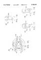
- FIG. 3is a top plan view showing the crimp members and dispenser of this invention.
- FIGS. 4(a), 4(b), 4(c) and 4(d)are front elevational views of the jaws of the apparatus of FIG. 1 illustrating one aspect of the method of this invention
- FIG. 5is a perspective view illustrating the use of the surgical wire in conjunction with the crimp member of this invention.
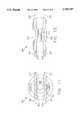
- FIGS. 6(a), 6(b) and 6(c)are partial side elevation views of the jaws of the apparatus of FIG. 1 illustrating another aspect of the method of this invention
- FIG. 7is a perspective, exploded view of the pivot of the apparatus of FIG. 1;
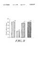
- FIG. 8is a bar graph showing the tensile strength of wire fastened using different methods
- FIG. 9is a front elevational view of a crimp member illustrative of an embodiment of the invention.
- FIG. 10is a front elevational view of the crimp member of FIG. 9, shown in a crimped condition
- FIG. 11is a front elevational view of another crimp member, illustrative of an alternative embodiment of the invention.
- FIG. 12is a front elevational view of the crimp member of FIG. 11, shown in a crimped condition;
- FIG. 13is a front elevational view of another crimp member, illustrative of another alternative embodiment of the invention.
- FIG. 14is a front elevational view of the crimp member of FIG. 13, shown in a crimped condition
- FIG. 15is a front elevational view of still another crimp member, illustrative of yet another embodiment of the invention.
- FIG. 16is a side elevational view of a crimp member formed in accordance with the present invention.
- FIG. 17is a side elevational view of another form of crimp member.
- FIG. 18is a side elevational view of still another form of crimp member.
- Tightening and crimping apparatus 10includes a pair of operating handles 12 and 14, a ratchet handle 16, jaws 18 and 20, stop 22, wire holder 84, springs 24 and 26, and pivots 28, 30, 32 and 34.
- Handles 12 and 14are pivotally coupled to one another at pivot 28. Handles 12 and 14 are pivotally secured at respective ends 36 and 38 to respective jaws 18 and 20 at pivots 30 and 32 respectively. Ends 36 and 38 are closely spaced from pivot 28 and are disposed on a side of pivot 28 opposite of proximal ends 13 and 15 of respective handles 12 and 14 to provide the desired mechanical advantage to jaws 18 and 20. Jaws 18 and 20 are pivotally attached to one another at pivot 34, which is positioned closely adjacent the nose ends 40 and 42 of respective jaws 18 and 20 so that the required crimping force is applied to ends 40 and 42. Handles 12 and 14 operate in a conventional manner such that movement of respective proximal ends 13 and 15 towards one another causes handles 12 and 14 to pivot about pivot 28.
- Spring 24biases proximal ends 13 and 15 of respective handles 12 and 14 away from one another.
- Spring 26biases ratchet handle 16 into its home position adjacent handle 12 so that when the ratcheting mechanism is used, as will be described hereinafter, handle 16 is automatically returned to its home position.
- Spring 24can be any commonly used mechanism for urging handles 12 and 14 apart at their distal ends.
- spring 24includes two preformed, resilient, metal strips 44 and 46 which are secured at one end 50 to respective handles 12 and 14 adjacent respective proximal ends 13 and 15 thereof. The opposite ends of strips 44 and 46 are either secured together at point 48, or are configured with interlocking tongues 47 and grooves such that they are urged into constant contact at point 48.
- Spring 26also may be any commonly used biasing mechanism.
- spring 26includes a preformed, resilient metal strip 52 and cam follower 54.
- One end of strip 52is attached to the proximal end of handle 16.
- Follower 54is journalled in the other end of strip 52.
- Follower 54rides along a cam surface 56 formed on the inside surface of handle during movement of handle 16 about pivot 28.
- Strip 52urges handle 16 back to its home position adjacent handle 12 upon the release of a pivoting force on ratchet handle 16.
- each of handles 12 and 14, as well as ratchet handle 16includes a textured surface 17 to assist in the manual grasping and manipulation thereof.
- Textured surface 17may comprise a plurality of parallel slots or depressions 41, abrasions providing a toughened surface or any other type of textured surface which provides the desired tactile sensation and frictional grip.
- Ends 40 and 42each include a recess 58.
- Recess 58 on each end 40 and 42is located between an overhanging lip 60 and a lower surface 62.
- the two recesses 58 on ends 40 and 42confront each other and together form one large recess sized to accept a crimp member 200, as described hereinafter (See FIG. 3).
- the space between surface 62 and lip 60 in each recess 58is approximately equal to the thickness of a crimp member 200 so that crimp member 200 is held in position in combined recesses 58 by overhanging lips 60.
- Disposed on ends 40 and 42are respective slotted guides 64 and 66.
- Guide 64is disposed on one side of apparatus 10 on end 42 directly below recess 58, while guide 66 is disposed on the opposite side of apparatus 10 on end 40 below recess 58.
- Guides 64 and 66each include a slot 68 adapted to receive a length of wire 202, as will be more fully described hereinafter.
- stop 22Positioned between pivots 30 and 32 and pivot 34 is a slidable stop 22. (See FIGS. 6(a)-6(c)).
- stop 22includes a spring 76 and a shaft 70 which passes laterally through apparatus 10 between jaws 18 and 20.
- Knobs 72 and 74typically are mounted on opposite ends of shaft 70 and each knob 72 and 74 has concentric grooves or the like on an exterior surface to allow for gripping thereof. Shaft 70, and thus knobs 72 and 74 are permitted to slide toward and away from ends 40 and 42 between jaws 18 and 20,
- Spring 76is a compression spring and is secured at one end to shaft 70 and at the other end to a fixed member 78 which extends between jaws 18 and 20. Spring 76 biases shaft 70 toward ends 40 and 42.
- Semi-circular slots 80a, 80b and 82a, 82bare provided in respective jaws 18 and 20 and extend parallel to shaft Confronting slots 80a and 80b in respective jaws 18 and 20 form one large circular slot 80, and confronting slots 82a and 82b form large circular slot 82.
- Shaft 70nests in slots 80 and 82 to allow jaws 18 and 20 to be in contacting relation.
- Shaft 70normally nests in slot 80 under the influence of spring 76. In this position, jaws 18 and 20 can be closed and reopened without interference from shaft 70.
- handles 12 and 14are pivoted toward one another at proximal ends 13 and 15 to form a space between jaws 18 and 20.
- Shaft 70is slid manually from from slot 80 into slot 82 using knobs 72, 74 and handles 12 and 14 are allowed to return to their normally spaced condition under the influence of spring 24.
- Handles 12 and 14are again pivoted toward one another at respective proximal ends 13 and 15, causing ends 40 and 42 to move toward one another.
- the space between jaws 20 and 22then becomes larger, permitting shaft 70 to ride out of slot 82 under the influence of spring 76 and into the space formed between jaws 20 and 22.
- spring 24urges handles 12 and 14 apart, capturing shaft 70 in the space between jaws 18 and 20 to retain ends 40 and 42 in a partially closed position.
- the spacing between ends 40 and 42is determined by the position of shaft 70 relative to slots 80 and 82 in the space between jaws 18 and 20. The closer shaft 70 is to slot 80, the closer is the spacing between ends 40 and 42. The more handles 12 and 14 are squeezed together, the closer is the spacing between ends 40 and 42 and the farther shaft 70 travels toward slot 80.
- a crimp member 200may be held in place within recesses 58 without crimping and with the desired applied force by selecting the proper spacing between ends 40 and 42.
- handles 12 and 14are squeezed farther together to push ends 40 and 42 farther together, the crimp member 200 disposed within recess 58 is crimped. At the same time, the space between jaws 18 and 20 is increased, thus releasing shaft 70 to return to slot 80 under the influence of spring 76. Thereafter, once crimp member 200 has been fully crimped, handles 12 and 14 are returned to their fully open position by spring 24 to allow removal of the apparatus 10.
- Pivot 28will now be described with particular reference to FIG. 6(a), 6(b), 6(c) and FIG. 7.
- Pivot 28includes a pair of ratchet mechanisms 90 and 92, capstans 94 and 95, and a coupling 96 between handles 12 and 14.
- Coupling 96joins handles 12 and 14 and includes a ring 98 on handle 12 which is disposed between and is coaxial with two spaced, coaxial rings 97 and 99 on handle 14. Rings 97, 98 and 99 typically are machined from the material of their respective handles.
- ratchet mechanisms 90 and 92are disposed on opposite sides of pivot 28. However, mechanisms 90 and 92 are linked so that they rotate in synchronization. Mounted onto each mechanism 90 and 92 is an associated capstan 94 and 95 which grabs and coils an end of a surgical wire 202 in response to movement of handle 16.
- Mechanism 90includes a pair of coaxially stacked, opposed discs 100 and 104 which are biased together by spring 106.
- the opposed, mating surfaces of discs 100 and 104are formed of steps, each of which comprises a sloping, camming surface 108 and a shoulder 110 which is substantially perpendicular to surface 108.
- stepseach of which comprises a sloping, camming surface 108 and a shoulder 110 which is substantially perpendicular to surface 108.
- Disc 100is formed on a surface of amount 102.
- Mount 102includes a shaft 103 which extends through rings 97, 98 and 99, as well as through a hole in the center of disc 104, the center of spring 106 and a hole in the end of handle 16.
- the hole in the center of disc 104preferably is hexagonal in shape.
- a hex nut 112is attached to the end of handle 16 and surrounds the hole therein. Nut 112 seats in the hole in the center of disc 104 so that disc 104 rotates in response to the rotation of handle 16.
- Mechanism 92includes a similar set of components, including disc 120, disc 122 and spring 124.
- Discs 120 and 122are coaxially stacked and are urged into contact by spring 124.
- Confronting surfaces of discs 120 and 122carry steps comprising sloping camming surfaces 126 and shoulders 128, similar to surfaces 108 and shoulders 110 found on the surfaces of discs 100 and 104.
- Shaft 130is affixed to the center of disc 120 and passes through a hole in the center of disc 122 and a hole in the center of spring 124. Projections 132 on the end of shaft 130 mate with corresponding grooves formed on the end of shaft 103, while projections 133 on the end of shaft 103 extend into corresponding grooves formed on the end of shaft 130. This connection locks shaft 130 to shaft 103. Rotation of disc 100 by handle 16 produces comparable rotation of disc 120.
- Circular disc 134is secured against rotation with respect to handle 14 by means of a screw (not shown) extending through a hole 135.
- a hex nut (not shown) secured to a side of disc 134 opposite handle 14seats in a hexagonal hole in disc 122.
- disc 122is locked against rotation with respect to handle 14. Therefore, rotation of disc 120 is permitted only in a direction in which surfaces 126 of disc 120 are permitted to slide along similarly formed surfaces 126 on disc 122, a counter-clockwise direction as shown in FIG. 7. However, should an attempt to be made to rotate disc 120 in the opposite direction, such as a clockwise direction as shown in FIG. 7, such rotation would be prevented by the engagement of shoulders 128 on disc 120 with shoulders 128 on disc 122.
- disc 120can be rotated in only the one direction. Since disc 120 is locked to disc 100 by shafts 130 and 103, disc 100 is also prevented from rotating in an opposite direction, or in a clockwise direction as shown in FIG. 7. As a consequence, handle 16 is only permitted to rotate discs 100 and 120 in a single direction, a counter-clockwise direction as shown in FIG. 7. Handle 16 is permitted to return to its home position under the influence of spring 26. Rotation of disc 104 with respect to disc 100 in that opposite direction, a clockwise direction as shown in FIG. 7, is permitted, since surfaces 108 on disc 100 ride along surfaces 108 on disc 104, urging discs 100 and 104 apart under the influence of spring 106 as handle 16 rotates.
- both ratchet mechanisms 90 and 92are operated in synchronism.
- Capstans 94 and 95each may comprise any mechanism for applying a tractive force to a wire, but preferably are formed as shown in FIG. 7 and are preferably adapted to have a wire coiled thereabout as they are rotated.
- Capstan 94is associated with ratchet mechanism 90, while capstan 95 is associated with ratchet mechanism 92.
- capstans 94 and 95are disposed on opposite sides of handles 12 and 14.
- Capstan 94includes a pair of spaced plates 136 and 138. Plates 136 and 138 are held together by screws 140 or other like fastening devices.
- Plate 136seats in a recess in mount 102, and screws 140 are inserted into correspondingly threaded holes in mount 102.
- Each plate 136 and 138has a generally flat center portion 142 which abuts a similarly configured center portion 142 in the other of plates 136 and 138.
- Each plate 136 and 138has an annularly shaped, toughened surface 144 which slopes downwardly away from portion 142 to the perimeter of the plate.
- surface 144comprises a series of radially extending steps. The steps include surfaces angled with respect to the bottom surface of plates 136 and 138 and shoulders which are generally perpendicular to the angled surfaces.
- Capstan 94is adapted to grip and coil a portion of the wire 202 in response to ratcheting movement of handle 16.
- surfaces 144should be configured to facilitate the gripping and coiling of the wire.
- the wirewill migrate toward the center or toward portion 142, thus allowing accommodation for additional wire to be wound about the capstan.
- Capstan 95is substantially identical to capstan 94 and includes plates 146 and 148. Plates 146 and 148 are held in place by screws 150 or other like fixation devices. Screws 150 are threadably mounted onto disc 120. Both of plates 146 and 148 include a sloping, toughened surface 144 and central portion 142 like plates 136 and 138, and are otherwise substantially identical to plates 136 and 138 of capstan 94.
- Pivot 28is held together by a screw 152, the head of which seats in disc 120, and the shaft of which passes through disc 120 and rings 97, 98 and 99.
- the shaft of screw 152is threadably secured to mount 102.
- Wire holder 84is typically U-shaped or is formed into the shape of a rectangle in which one side is missing, and includes two arms 86 and 87 and a cross member 79 linking arms 86 and 87. Member 79 is secured to handle 12 by a screw or the like and serves to anchor holder 84. Arms 86 and 87 each extend beneath an associated capstan 94 or 95. Each arm 86 and 87 is provided with a shoulder 91 and a finger 89 which extends beyond shoulder 91. The end of a wire wrapped about capstan 94 or 95 is bent around shoulder 91 to hold it in place during the beginning stages of the wire tightening procedure. Finger 89 prevents the wire from sliding off shoulder 91.
- Holder 84also includes a shoulder 77 which acts as a stop to limit the movement of handle 16 in a clockwise direction, as shown in FIG. 1, under the influence of spring 26. Shoulder 77 defines the home position of handle 16.
- Each crimp member 200typically is donut-shaped and includes a ring with a central, axially aligned hole 201 and two generally parallel channels 203 extending in a direction generally normal to the central axis of the ring of member 200. Channels 203 extend through the ring on either side of hole 201 and may or may not intersect hole 201.
- crimp member dispenser 205includes a handle 207 and two parallel arms 209 which are bent slightly outwardly away from one another at their distal tips. Arms 209 extend through the two channels 203 of members 200 and allow members 200 to be mounted sequentially on arms 209.
- Arms 209are spaced apart a distance adjacent handle 207 which is greater than their spacing in the middle of arms 209 to limit movement of members 200 toward handle 207.
- dispenser 205is formed of a single wire bent in half and twisted adjacent the bend to form handle 207.
- this inventionmay be used for any operation in which it is desired to use a surgical wire, such as, for example, reconstructive spine surgery, spine trauma surgery, total hip arthroplasty, open-heart surgery, closures of the sternum, oral/facial surgery to fix mandibular fractures, repair of trochanteric osteotomies, the repair, reconstruction or augmentation of ruptured or sprained ligaments and tendons, and fracture fixation, including fixing of long bone fractures, repair of olecron fractures, and repair of patella fractures.
- a surgical wiresuch as, for example, reconstructive spine surgery, spine trauma surgery, total hip arthroplasty, open-heart surgery, closures of the sternum, oral/facial surgery to fix mandibular fractures, repair of trochanteric osteotomies, the repair, reconstruction or augmentation of ruptured or sprained ligaments and tendons, and fracture fixation, including fixing of long bone fractures, repair of olecron fractures, and repair of patella fractures.
- wire 202may be a single strand of wire, or a cable formed of multiple strands of wire twisted together.
- Wire 202may be formed of metal, although this invention also may be used with a non-metallic wire formed of a plastic material such as NYLON®, DELRIN®, DACRON®, or KEVLAR® or any other biologically compatible material.
- a non-metallic wiremay either be a monofilament wire or a multi-filament cable formed of strands twisted or braided together.
- Such a non-metallic wireis preferred in some applications, since it does not degrade or obscure CAT scans or MRI images. Also, such non-metallic wires tend to have higher fatigue strengths. For simplification, no bone parts or pieces are shown in the drawings, but it is to be understood that wire 202 would encircle a bone or bone fragments, or soft tissues.
- shaft 70is moved by manipulation of knobs 72 and 74 into slot 82 in the manner previously discussed.
- a crimp member 200is lowered into recesses 58 in nose ends 40 and 42. This procedure is accomplished, as shown in FIG. 3 and FIGS. 4(a)-(c).
- dispenser 205is positioned such that the crimp member 200 which is disposed on the distal ends of arms 209 is positioned within recesses 58 while ends 40 and 42 are in a fully opened position.
- Handle 207 of dispenser 205is held by the surgeon in one hand, while apparatus 10 is held in his other hand.
- crimp member 200While the most distally disposed crimp member 200 is being held within recesses 58, the surgeon begins pivoting the distal ends of handles 12 and 14 toward one another to close jaws 18 and 20 to grasp crimp member 200. Once crimp member 200 is held in place without deformation by jaws 18 and 20, dispenser 205 is removed by withdrawing the distal ends of arms 209 from channels 203 of crimp member 200.
- shaft 70pops out of slot 82 under the influence of spring 76, as a gap is formed between jaws 18 and 20.
- spring 76the proximal ends of handles 12 and 14 are no longer pivoted toward one another.
- shaft 70is disposed intermediate holes 80 and 82 and is trapped in that position by jaws 18 and 20. Shaft 70 prevents spring 24 from returning handles 12 and 14 to their fully separated positions and thus prevents ends 40 and 42 from separating.
- crimp member 200is tightly held in recesses 58 without being crimped.
- the surgical wire 202is wrapped about the bone or bone fragments in accordance with the desired surgical procedure.
- One end of wire 202is inserted through a channel 203 of crimp member 200 from the side of ends 40 and 42 on which guide 62 is located.
- Wire 202is passed through the channel 203 which is not associated with surface 62, and wire 202 exits the other side of channel 203 directly above surface 66.
- This free end of wire 202passes through slot 68 in guide 66 and is wrapped about capstan 95 between plates 144 and 146 in a clockwise direction, as shown in FIG. 2.
- This end of wire 202is wrapped around capstan 95 once and is bent about shoulder 91 of arm 87 and away from finger 89.
- wire 202is passed through the other channel 203 of member 200 from a side of the apparatus having guide 66. This end of wire 202 exits channel 203 directly aligned with surface 62 and passes through slot 68 thereof. Wire 202 then is wrapped about capstan 94 between plates 136 and 138 in a counter-clockwise direction, as shown in FIG. 1. After being wrapped once about capstan 94, the end of the wire is bent about shoulder 91 of arm 86 and away from finger
- ratchet handle 16is moved repeatedly in a counter-clockwise direction as shown in FIG. 1 and in FIG. 6(a). This operation can be performed with one hand. Handle 14 resides in the palm, and the surgeon's fingers are wrapped about ratchet handle 16 to repeatedly draw handle 16 toward handle 14 and release handle 16 to allow handle 16 to return to its home position, as shown in FIG. 1. This repeated motion of ratchet handle 16 wraps both ends of wire 202 simultaneously around capstans 94 and 95. As more wire is wrapped around each capstan, wire 202 tends to move inwardly along surfaces 144 toward center section 142. While the wire was initially wrapped about arms 86 and 87 to hold it in place, the free ends are released once the tightening process begins. Once the desired tractive force on wire 202 has been achieved, the tightening process has been completed.
- wire 202is crimped in position.
- This crimpingis accomplished by pivoting the proximal ends of handles 12 and 14 farther together.
- this crimping processcan be accomplished using a single hand, since the mechanical advantage gained by these handles with respect to the ends of the jaws is substantial.
- the length of handles 12 and 14is much greater than the very short distance from pivot 28 to pivots 30 and 32.
- the distance from pivots 30 and 32 to pivot 34is much greater than the distance from pivot 34 to ends 40 and 42, Therefore, an ordinary physician using one hand can apply the pressure necessary to adequately crimp member 200.
- ends 40 and 42close and crimp member 200 deforms.
- the spacing between jaws 18 and 20increases and shaft 70 begins to move toward pivot 34 under the influence of spring 76, until shaft 70 again resides in slot 80.
- jaws 18 and 20are permitted to completely open under the influence of spring 24 to allow removal of the crimped crimping member 200.
- Member 200is deformed into a very small package, as shown in FIG. 4(d), and holds wire 202 in the desired location with the desired tractive force.
- the provision of a central hole 201allows the desired deformation of crimping member 200.
- the resulting size of member 200is not substantially larger than the combined width of the two sections of wire 202. For this reason, the resulting crimped wire produces little irritation and can be used in percutaneous locations.
- an important feature of the present inventionis the provision of a crimp member which can be deformed using a minimum of deformation force, yet still provides a maximum of holding power. This is achieved in the present invention by forming the crimp member with an annular configuration, i.e., as a disk element 200 with a central, axially aligned hole 201, and with two generally parallel, wire-receiving channels 203 extending through the disk in a direction generally perpendicular to the central axis of the disk.
- Applicant's constructionprovides a crimp member which can be deformed with a minimum of deformation force, since the crimp member can be easily collapsed radially inwardly upon its hollow center.
- the crimp memberprovides a maximum of holding power, since radial deformation of the crimp member in a direction generally transverse to the two generally parallel, wire-receiving channels will result in lateral displacement of selected portions of the crimp member, and in lateral displacement of adjacent portions of the wires, relative to the remaining portions of the crimp member and the wires.
- the rim of crimp member 200will be driven radially inwardly by diametrically-opposed forces applied by the two jaws of tightening and crimping apparatus 10 so as to collapse the crimp member about its center hole 201.
- wires 202will be laterally displaced in the affected regions of the crimp member.
- the remaining portions of crimp member 200i.e., the portions of crimp member 200 adjacent to where channels 203 open on the outer perimeter of the crimp member
- the adjacent portions of wires 202will be relatively unaffected.
- crimp member 200 and wires 202are formed out of stainless steel, the lateral displacement occurring during setting is typically large enough to cause wires 202 to take on a set. Once selected portions of the rim of crimp member 200, and the adjacent portions of wires 202, have been laterally displaced in the foregoing manner, crimp member 200 and wires 202 will cooperate with one another so as to form a unique mechanical interlock which will provide unusually strong holding power against any movement of wires 202 relative to crimp member 200.
- crimp member 200may be formed in a variety of different configurations without departing from the scope of the present invention. Thus, for example, in FIGS. 9, 11 and 13, there are shown three different embodiments of crimp member 200.
- FIG. 9there is illustrated an embodiment of crimp member 200 wherein channels 203 are arranged such that wires 202 pass in part through the crimp member's central hole 201.
- wires 202 located near the center of crimp member 200are laterally displaced so that they either engage or nearly engage one another, as shown in FIG. 10.
- those portions of channels 203 and wires 202 located near the periphery of the crimp memberremain relatively undisturbed.
- portions of the wires 202 located within the crimp member 200are caused to bend precipitously within crimp member 200, thereby adding to the locking engagement of crimp member 200 with wires 202.
- FIG. 11there is illustrated an embodiment of crimp member 200 wherein channels 203 are arranged such that wires 202 pass outboard of the crimp member's central hole 201.
- the crimping of member 200(FIG. 12) similarly bends wires 202 toward each other at the center area of crimp member 200, thereby enhancing the grip of crimp member 200 on wires 202.
- wires 202are oriented so as to pass through the crimp member's central hole 201 and are therefore not spaced apart from each other to the extent shown in FIGS. 9 and 11. Accordingly, crimping (FIG. 14) does not displace wires 202 as dramatically as in the embodiments of FIGS. 9 and 11 but, nevertheless, bends in wires 202 are still introduced, providing more secure interlocking of crimp member 200 and wires 202.
- crimp members 200are formed so that channels 203 extend parallel to one another. It should also be appreciated, however, that crimp member 200 could be formed so that channels 203 do not extend parallel to one another. See, for example, FIG. 15, which shows such a construction.
- crimp members 200are preferably constructed so that channels 203 lie in substantially the same plane.
- crimp members 200are formed so that the crimp member's two channels 203 have substantially the same diameters. It should also be appreciated, however, that the two channels 203 might have different diameters if desired, e.g., if two different sized wires 202 were to be crimped together using crimp member 200. See, for example, FIG. 18, where two different sized channels 203 are provided.
- crimp member 200could have an outer configuration other than round, e.g., crimp member 200 could have a polygonal outer configuration. By way of example, crimp member 200 could have a rectangular outer configuration.
- the crimp member's central hole 201could have a configuration other than round, e.g., center hole 201 could be formed with a polygonal configuration.
- Crimp member 200might also be formed with more than two wire-receiving channels 203, e.g., crimp member 200 might be formed with three or four channels 203.
- FIG. 8illustrates the tensile strength of solid 18 gauge surgical wire compared with wire fastened using various methods.
- FIG. 8is a bar graph in which the vertical axis represents strength in pounds.
- Bar 160represents the tensile strength of solid 18 gauge 316 stainless steel wire.
- Bar 162represents the tensile strength of 18 gauge stainless steel wire which has been twisted together.
- Bar 164represents the tensile strength of 18 gauge stainless steel wire which has been tied in a square knot.
- Bar 166represents the tensile strength of 18 gauge stainless steel wire which has been crimped according to the method of the present invention. As can be seen, wire which has been crimped according to the method of this invention has substantially the same tensile strength as solid, uncrimped 18 gauge stainless steel wire.
- Apparatus 10is sufficiently small and is so configured that it can be grasped and operated by one hand. Each step of the process requires no more than two hands. Furthermore, only a single tool performs both the tightening and crimping processes. No additional elements or pieces of apparatus are required to either tighten or crimp. Moreover, the resulting crimped wire has the same strength as uncrimped wire and the size of the crimp is so small, it can be placed percutaneously.
Landscapes
- Health & Medical Sciences (AREA)
- Orthopedic Medicine & Surgery (AREA)
- Life Sciences & Earth Sciences (AREA)
- Surgery (AREA)
- Medical Informatics (AREA)
- Engineering & Computer Science (AREA)
- Biomedical Technology (AREA)
- Heart & Thoracic Surgery (AREA)
- Nuclear Medicine, Radiotherapy & Molecular Imaging (AREA)
- Molecular Biology (AREA)
- Animal Behavior & Ethology (AREA)
- General Health & Medical Sciences (AREA)
- Public Health (AREA)
- Veterinary Medicine (AREA)
- Neurology (AREA)
- Surgical Instruments (AREA)
Abstract
Description
Claims (23)
Priority Applications (3)
| Application Number | Priority Date | Filing Date | Title |
|---|---|---|---|
| US08/488,047US5720747A (en) | 1994-03-11 | 1995-06-07 | Apparatus for crimping a surgical wire |
| AU63289/96AAU6328996A (en) | 1995-06-07 | 1996-06-06 | Crimp for a surgical wire |
| PCT/US1996/009487WO1996039976A1 (en) | 1995-06-07 | 1996-06-06 | Crimp for a surgical wire |
Applications Claiming Priority (2)
| Application Number | Priority Date | Filing Date | Title |
|---|---|---|---|
| US08/212,038US5545168A (en) | 1994-03-11 | 1994-03-11 | Apparatus for both tensioning and crimping a surgical wire |
| US08/488,047US5720747A (en) | 1994-03-11 | 1995-06-07 | Apparatus for crimping a surgical wire |
Related Parent Applications (1)
| Application Number | Title | Priority Date | Filing Date |
|---|---|---|---|
| US08/212,038Continuation-In-PartUS5545168A (en) | 1994-03-11 | 1994-03-11 | Apparatus for both tensioning and crimping a surgical wire |
Publications (1)
| Publication Number | Publication Date |
|---|---|
| US5720747Atrue US5720747A (en) | 1998-02-24 |
Family
ID=23938131
Family Applications (1)
| Application Number | Title | Priority Date | Filing Date |
|---|---|---|---|
| US08/488,047Expired - LifetimeUS5720747A (en) | 1994-03-11 | 1995-06-07 | Apparatus for crimping a surgical wire |
Country Status (3)
| Country | Link |
|---|---|
| US (1) | US5720747A (en) |
| AU (1) | AU6328996A (en) |
| WO (1) | WO1996039976A1 (en) |
Cited By (133)
| Publication number | Priority date | Publication date | Assignee | Title |
|---|---|---|---|---|
| US5928243A (en) | 1997-07-16 | 1999-07-27 | Spinal Concepts, Inc. | Pedicle probe and depth gage |
| US5935133A (en) | 1997-08-26 | 1999-08-10 | Spinal Concepts, Inc. | Surgical cable system and method |
| US5989250A (en) | 1996-10-24 | 1999-11-23 | Spinal Concepts, Inc. | Method and apparatus for spinal fixation |
| US6010525A (en)* | 1997-08-01 | 2000-01-04 | Peter M. Bonutti | Method and apparatus for securing a suture |
| US6030410A (en)* | 1998-05-18 | 2000-02-29 | Zurbruegg; Heinz Robert | Sternal closure technique and kit for performing same |
| US6030389A (en) | 1997-08-04 | 2000-02-29 | Spinal Concepts, Inc. | System and method for stabilizing the human spine with a bone plate |
| US6033429A (en)* | 1998-01-13 | 2000-03-07 | Cardiac Assist Technologies, Inc. | System, apparatus and method for closing severed bone or tissue of a patient |
| US6045572A (en)* | 1998-10-16 | 2000-04-04 | Cardiac Assist Technologies, Inc. | System, method and apparatus for sternal closure |
| US6045579A (en) | 1997-05-01 | 2000-04-04 | Spinal Concepts, Inc. | Adjustable height fusion device |
| US6053921A (en) | 1997-08-26 | 2000-04-25 | Spinal Concepts, Inc. | Surgical cable system and method |
| US6080185A (en)* | 1998-10-16 | 2000-06-27 | Cardiac Assist Technologies, Inc. | Stop mechanism and method therefor |
| US6132430A (en) | 1996-10-24 | 2000-10-17 | Spinal Concepts, Inc. | Spinal fixation system |
| US6159234A (en)* | 1997-08-01 | 2000-12-12 | Peter M. Bonutti | Method and apparatus for securing a suture |
| GB2351672A (en)* | 1999-05-05 | 2001-01-10 | Acumed Inc | Wire clamp assembly |
| US6296643B1 (en) | 1999-04-23 | 2001-10-02 | Sdgi Holdings, Inc. | Device for the correction of spinal deformities through vertebral body tethering without fusion |
| US6299613B1 (en) | 1999-04-23 | 2001-10-09 | Sdgi Holdings, Inc. | Method for the correction of spinal deformities through vertebral body tethering without fusion |
| US6387099B1 (en) | 2000-03-24 | 2002-05-14 | Synthes (Usa) | Surgical cable crimp |
| US20020058939A1 (en)* | 1997-08-04 | 2002-05-16 | Spinal Concepts, Inc. | System and method for stabilizing the human spine with a bone plate |
| US6436099B1 (en) | 1999-04-23 | 2002-08-20 | Sdgi Holdings, Inc. | Adjustable spinal tether |
| US20040220569A1 (en)* | 1999-07-07 | 2004-11-04 | Wall Eric J | Spinal correction system |
| US20040220616A1 (en)* | 2000-03-13 | 2004-11-04 | Bonutti Peter M. | Method and device for securing body tissue |
| US20050033298A1 (en)* | 2001-10-31 | 2005-02-10 | Ortho Development Corporation | Cervical plate for stabilizing the human spine |
| US20050043734A1 (en)* | 2003-04-24 | 2005-02-24 | Kay David B. | Method and device for bone stabilization using a threaded compression wire |
| US20050131430A1 (en)* | 2003-12-12 | 2005-06-16 | Arvik Enterprises, Llc | Suturing device |
| US20050165448A1 (en)* | 1997-08-28 | 2005-07-28 | Egan Thomas D. | Fused loop of filamentous material and apparatus for making same |
| US20050216059A1 (en)* | 2002-09-05 | 2005-09-29 | Bonutti Peter M | Method and apparatus for securing a suture |
| US6964664B2 (en) | 2000-01-06 | 2005-11-15 | Spinal Concepts Inc. | System and method for stabilizing the human spine with a bone plate |
| US20060089646A1 (en)* | 2004-10-26 | 2006-04-27 | Bonutti Peter M | Devices and methods for stabilizing tissue and implants |
| US20060106391A1 (en)* | 2004-11-12 | 2006-05-18 | Huebner Randall J | Wire systems for fixing bones |
| US20060229623A1 (en)* | 2004-10-26 | 2006-10-12 | Bonutti Peter M | Tissue fixation system and method |
| US20060235470A1 (en)* | 2000-03-13 | 2006-10-19 | Bonutti Peter M | Method of using ultrasonic vibration to secure implantable member to body tissue |
| US20060265009A1 (en)* | 2000-05-03 | 2006-11-23 | Bonutti Peter M | Method of securing body tissue |
| US20060282085A1 (en)* | 2004-11-09 | 2006-12-14 | Arthrotek, Inc. | Soft tissue conduit device |
| US20070270878A1 (en)* | 2006-03-30 | 2007-11-22 | Leisinger Steven R | Tensioning device, kit and related method |
| US20070270861A1 (en)* | 2006-03-30 | 2007-11-22 | Leisinger Steven R | Kit for use in orthopaedic procedures, device and related menthod |
| US20070270833A1 (en)* | 2006-02-07 | 2007-11-22 | Bonutti Peter M | Methods and devices for trauma welding |
| US20080039873A1 (en)* | 2004-03-09 | 2008-02-14 | Marctec, Llc. | Method and device for securing body tissue |
| US20080082128A1 (en)* | 2006-09-29 | 2008-04-03 | Arthrotek, Inc. | Method and apparatus for forming a self-locking adjustable suture loop |
| US20080132932A1 (en)* | 2006-08-16 | 2008-06-05 | Biomet Sports Medicine, Inc. | Chondral Defect Repair |
| US20080140116A1 (en)* | 1999-08-09 | 2008-06-12 | Bonutti Peter M | Method and apparatus for securing tissue |
| US20080195145A1 (en)* | 2007-02-13 | 2008-08-14 | Bonutti Peter M | Tissue fixation system and method |
| US20080249448A1 (en)* | 2007-04-06 | 2008-10-09 | Stevenson Craig G | Cable-based orthopedic bracing system |
| US20080249532A1 (en)* | 2007-04-06 | 2008-10-09 | Synthes U.S.A. | Securing device to secure fixation devices to bone portions |
| US20080255613A1 (en)* | 2007-04-10 | 2008-10-16 | Biomet Sports Medicine, Inc. | Adjustable knotless loops |
| US20080294260A1 (en)* | 2007-05-22 | 2008-11-27 | Wayne Gray | Spinal implant system and method |
| US20090105717A1 (en)* | 2007-10-17 | 2009-04-23 | Stryker Trauma Gmbh | Cam-locking of cable for fracture plate |
| US20090163938A1 (en)* | 2003-04-30 | 2009-06-25 | Bonutti Peter M | Tissue fastener and methods for using same |
| US20090216269A1 (en)* | 2006-04-18 | 2009-08-27 | Axya Medical, Inc, | Multicomponent fused suture loop and apparatus for making same |
| US20090287249A1 (en)* | 2005-09-21 | 2009-11-19 | Children's Hospital Medical Center And Spineform Llc | Orthopedic implant |
| US20090312776A1 (en)* | 2006-02-03 | 2009-12-17 | Biomet Sports Medicine, Llc | Method and Apparatus for Coupling Soft Tissue to a Bone |
| US7637952B2 (en) | 2002-03-11 | 2009-12-29 | Zimmer Spine, Inc. | Instrumentation and procedure for implanting spinal implant devices |
| US20100030240A1 (en)* | 2006-12-26 | 2010-02-04 | Vladimir Brailovski | Closure apparatus |
| US20100087857A1 (en)* | 2004-11-05 | 2010-04-08 | Stone Kevin T | Soft Tissue Repair Device and Method |
| US20100094294A1 (en)* | 2008-10-10 | 2010-04-15 | Joel Gillard | Cerclage system for bone |
| US20100100138A1 (en)* | 2005-09-21 | 2010-04-22 | Reynolds Joseph E | Endoscopic Insturments and Mehod for Delivery of Spinal Implant |
| US7854750B2 (en) | 2002-08-27 | 2010-12-21 | P Tech, Llc. | Apparatus and method for securing a suture |
| US7959650B2 (en)* | 2006-09-29 | 2011-06-14 | Biomet Sports Medicine, Llc | Adjustable knotless loops |
| US8118836B2 (en) | 2004-11-05 | 2012-02-21 | Biomet Sports Medicine, Llc | Method and apparatus for coupling soft tissue to a bone |
| US8128658B2 (en) | 2004-11-05 | 2012-03-06 | Biomet Sports Medicine, Llc | Method and apparatus for coupling soft tissue to bone |
| US20120059377A1 (en)* | 2007-10-11 | 2012-03-08 | Karl Pierre Belliard | Bone fixing system and method of use |
| US8137382B2 (en) | 2004-11-05 | 2012-03-20 | Biomet Sports Medicine, Llc | Method and apparatus for coupling anatomical features |
| US8221454B2 (en) | 2004-02-20 | 2012-07-17 | Biomet Sports Medicine, Llc | Apparatus for performing meniscus repair |
| US8273106B2 (en) | 2006-02-03 | 2012-09-25 | Biomet Sports Medicine, Llc | Soft tissue repair and conduit device |
| US8292921B2 (en) | 2006-02-03 | 2012-10-23 | Biomet Sports Medicine, Llc | Soft tissue repair device and associated methods |
| US8298262B2 (en) | 2006-02-03 | 2012-10-30 | Biomet Sports Medicine, Llc | Method for tissue fixation |
| US8317825B2 (en) | 2004-11-09 | 2012-11-27 | Biomet Sports Medicine, Llc | Soft tissue conduit device and method |
| US8337525B2 (en) | 2006-02-03 | 2012-12-25 | Biomet Sports Medicine, Llc | Soft tissue repair device and associated methods |
| US8343227B2 (en) | 2009-05-28 | 2013-01-01 | Biomet Manufacturing Corp. | Knee prosthesis assembly with ligament link |
| US8361113B2 (en) | 2006-02-03 | 2013-01-29 | Biomet Sports Medicine, Llc | Method and apparatus for coupling soft tissue to a bone |
| US8409253B2 (en) | 2006-02-03 | 2013-04-02 | Biomet Sports Medicine, Llc | Soft tissue repair assembly and associated method |
| US8496657B2 (en) | 2006-02-07 | 2013-07-30 | P Tech, Llc. | Methods for utilizing vibratory energy to weld, stake and/or remove implants |
| US8500818B2 (en) | 2006-09-29 | 2013-08-06 | Biomet Manufacturing, Llc | Knee prosthesis assembly with ligament link |
| US8506597B2 (en) | 2011-10-25 | 2013-08-13 | Biomet Sports Medicine, Llc | Method and apparatus for interosseous membrane reconstruction |
| US8562645B2 (en) | 2006-09-29 | 2013-10-22 | Biomet Sports Medicine, Llc | Method and apparatus for forming a self-locking adjustable loop |
| US8562647B2 (en) | 2006-09-29 | 2013-10-22 | Biomet Sports Medicine, Llc | Method and apparatus for securing soft tissue to bone |
| US8574235B2 (en) | 2006-02-03 | 2013-11-05 | Biomet Sports Medicine, Llc | Method for trochanteric reattachment |
| US8597327B2 (en) | 2006-02-03 | 2013-12-03 | Biomet Manufacturing, Llc | Method and apparatus for sternal closure |
| US8652171B2 (en) | 2006-02-03 | 2014-02-18 | Biomet Sports Medicine, Llc | Method and apparatus for soft tissue fixation |
| US8652172B2 (en) | 2006-02-03 | 2014-02-18 | Biomet Sports Medicine, Llc | Flexible anchors for tissue fixation |
| US8672969B2 (en) | 2006-09-29 | 2014-03-18 | Biomet Sports Medicine, Llc | Fracture fixation device |
| US8771352B2 (en) | 2011-05-17 | 2014-07-08 | Biomet Sports Medicine, Llc | Method and apparatus for tibial fixation of an ACL graft |
| US8801783B2 (en) | 2006-09-29 | 2014-08-12 | Biomet Sports Medicine, Llc | Prosthetic ligament system for knee joint |
| US8808329B2 (en) | 1998-02-06 | 2014-08-19 | Bonutti Skeletal Innovations Llc | Apparatus and method for securing a portion of a body |
| US8840645B2 (en) | 2004-11-05 | 2014-09-23 | Biomet Sports Medicine, Llc | Method and apparatus for coupling soft tissue to a bone |
| US8845687B2 (en) | 1996-08-19 | 2014-09-30 | Bonutti Skeletal Innovations Llc | Anchor for securing a suture |
| US8845699B2 (en) | 1999-08-09 | 2014-09-30 | Bonutti Skeletal Innovations Llc | Method of securing tissue |
| US8936621B2 (en) | 2006-02-03 | 2015-01-20 | Biomet Sports Medicine, Llc | Method and apparatus for forming a self-locking adjustable loop |
| US8968364B2 (en) | 2006-02-03 | 2015-03-03 | Biomet Sports Medicine, Llc | Method and apparatus for fixation of an ACL graft |
| US9078644B2 (en) | 2006-09-29 | 2015-07-14 | Biomet Sports Medicine, Llc | Fracture fixation device |
| US9089323B2 (en) | 2005-02-22 | 2015-07-28 | P Tech, Llc | Device and method for securing body tissue |
| US9138222B2 (en) | 2000-03-13 | 2015-09-22 | P Tech, Llc | Method and device for securing body tissue |
| US9149281B2 (en) | 2002-03-20 | 2015-10-06 | P Tech, Llc | Robotic system for engaging a fastener with body tissue |
| US9149267B2 (en) | 2006-02-03 | 2015-10-06 | Biomet Sports Medicine, Llc | Method and apparatus for coupling soft tissue to a bone |
| US9241748B2 (en) | 2012-04-30 | 2016-01-26 | Acute Innovations Llc | System for binding bone |
| US9259217B2 (en) | 2012-01-03 | 2016-02-16 | Biomet Manufacturing, Llc | Suture Button |
| US9271713B2 (en) | 2006-02-03 | 2016-03-01 | Biomet Sports Medicine, Llc | Method and apparatus for tensioning a suture |
| US9271766B2 (en) | 2004-10-26 | 2016-03-01 | P Tech, Llc | Devices and methods for stabilizing tissue and implants |
| US9314241B2 (en) | 2011-11-10 | 2016-04-19 | Biomet Sports Medicine, Llc | Apparatus for coupling soft tissue to a bone |
| US9357991B2 (en) | 2011-11-03 | 2016-06-07 | Biomet Sports Medicine, Llc | Method and apparatus for stitching tendons |
| US9370350B2 (en) | 2011-11-10 | 2016-06-21 | Biomet Sports Medicine, Llc | Apparatus for coupling soft tissue to a bone |
| US9381013B2 (en) | 2011-11-10 | 2016-07-05 | Biomet Sports Medicine, Llc | Method for coupling soft tissue to a bone |
| US9439642B2 (en) | 2006-02-07 | 2016-09-13 | P Tech, Llc | Methods and devices for utilizing bondable materials |
| US9463012B2 (en) | 2004-10-26 | 2016-10-11 | P Tech, Llc | Apparatus for guiding and positioning an implant |
| US9538998B2 (en) | 2006-02-03 | 2017-01-10 | Biomet Sports Medicine, Llc | Method and apparatus for fracture fixation |
| US9615822B2 (en) | 2014-05-30 | 2017-04-11 | Biomet Sports Medicine, Llc | Insertion tools and method for soft anchor |
| US9700291B2 (en) | 2014-06-03 | 2017-07-11 | Biomet Sports Medicine, Llc | Capsule retractor |
| US9757119B2 (en) | 2013-03-08 | 2017-09-12 | Biomet Sports Medicine, Llc | Visual aid for identifying suture limbs arthroscopically |
| US9770238B2 (en) | 2001-12-03 | 2017-09-26 | P Tech, Llc | Magnetic positioning apparatus |
| US9801708B2 (en) | 2004-11-05 | 2017-10-31 | Biomet Sports Medicine, Llc | Method and apparatus for coupling soft tissue to a bone |
| US9820793B1 (en)* | 2014-04-21 | 2017-11-21 | Dallen Medical, Inc. | Tensioning devices and methods for dynamic suture systems |
| US9918827B2 (en) | 2013-03-14 | 2018-03-20 | Biomet Sports Medicine, Llc | Scaffold for spring ligament repair |
| US9918826B2 (en) | 2006-09-29 | 2018-03-20 | Biomet Sports Medicine, Llc | Scaffold for spring ligament repair |
| US9955980B2 (en) | 2015-02-24 | 2018-05-01 | Biomet Sports Medicine, Llc | Anatomic soft tissue repair |
| US10039543B2 (en) | 2014-08-22 | 2018-08-07 | Biomet Sports Medicine, Llc | Non-sliding soft anchor |
| US10052143B2 (en) | 2014-04-30 | 2018-08-21 | DePuy Synthes Products, Inc. | Tensioning instrument and related bone fixation systems and methods |
| US10058393B2 (en) | 2015-10-21 | 2018-08-28 | P Tech, Llc | Systems and methods for navigation and visualization |
| US10076377B2 (en) | 2013-01-05 | 2018-09-18 | P Tech, Llc | Fixation systems and methods |
| US10136886B2 (en) | 2013-12-20 | 2018-11-27 | Biomet Sports Medicine, Llc | Knotless soft tissue devices and techniques |
| US10357295B1 (en) | 2013-11-13 | 2019-07-23 | Mohammed A. Hajianpour | Apparatus and method for connecting opposite ends of a surgical wire wrapped around an internal body structure |
| US10517587B2 (en) | 2006-02-03 | 2019-12-31 | Biomet Sports Medicine, Llc | Method and apparatus for forming a self-locking adjustable loop |
| US10820935B2 (en) | 2017-02-03 | 2020-11-03 | Stryker European Holdings I, Llc | Tensioning cable locking device |
| US10912551B2 (en) | 2015-03-31 | 2021-02-09 | Biomet Sports Medicine, Llc | Suture anchor with soft anchor of electrospun fibers |
| US11246638B2 (en) | 2006-05-03 | 2022-02-15 | P Tech, Llc | Methods and devices for utilizing bondable materials |
| US11253296B2 (en) | 2006-02-07 | 2022-02-22 | P Tech, Llc | Methods and devices for intracorporeal bonding of implants with thermal energy |
| US11259792B2 (en) | 2006-02-03 | 2022-03-01 | Biomet Sports Medicine, Llc | Method and apparatus for coupling anatomical features |
| US11259794B2 (en)* | 2006-09-29 | 2022-03-01 | Biomet Sports Medicine, Llc | Method for implanting soft tissue |
| US11278331B2 (en) | 2006-02-07 | 2022-03-22 | P Tech Llc | Method and devices for intracorporeal bonding of implants with thermal energy |
| US11311287B2 (en) | 2006-02-03 | 2022-04-26 | Biomet Sports Medicine, Llc | Method for tissue fixation |
| US20230172602A1 (en)* | 2009-05-29 | 2023-06-08 | Biomet Sports Medicine, Llc | Method and apparatus for coupling soft tissue to a bone |
| US11698121B2 (en) | 2019-09-23 | 2023-07-11 | Fort Wayne Metals Research Products, Llc | Wire attachment |
| US12245759B2 (en) | 2008-08-22 | 2025-03-11 | Biomet Sports Medicine, Llc | Method and apparatus for coupling soft tissue to bone |
| US12329373B2 (en) | 2011-05-02 | 2025-06-17 | Biomet Sports Medicine, Llc | Method and apparatus for soft tissue fixation |
| US12419632B2 (en) | 2008-08-22 | 2025-09-23 | Biomet Sports Medicine, Llc | Method and apparatus for coupling anatomical features |
Families Citing this family (3)
| Publication number | Priority date | Publication date | Assignee | Title |
|---|---|---|---|---|
| FR2768612B1 (en)* | 1997-09-24 | 1999-10-29 | Jmed Sarl | ARTIFICIAL LIGAMENT FOR INTERVERTEBRAL ARTHROPLASTY AND APPARATUS FOR IMPLEMENTATION |
| DE202006018587U1 (en) | 2006-12-06 | 2007-03-15 | Zrinski Ag | Surgical instrument for implanting wire into bone, has grasping element with two grasping parts whereby by squeezing grasping parts together, support wire presses against clamping section |
| DE102022122391A1 (en) | 2022-09-05 | 2024-03-07 | Bricon Gmbh | Kirschner wire applicator |
Citations (3)
| Publication number | Priority date | Publication date | Assignee | Title |
|---|---|---|---|---|
| US4966600A (en)* | 1989-01-26 | 1990-10-30 | Songer Robert J | Surgical securance method |
| US5236434A (en)* | 1991-12-16 | 1993-08-17 | Callicrate Michael P | Method and apparatus for ligating a body part |
| EP0638292A1 (en)* | 1993-08-09 | 1995-02-15 | Kijuro Hayano | Wire fastening tool |
- 1995
- 1995-06-07USUS08/488,047patent/US5720747A/ennot_activeExpired - Lifetime
- 1996
- 1996-06-06WOPCT/US1996/009487patent/WO1996039976A1/enactiveSearch and Examination
- 1996-06-06AUAU63289/96Apatent/AU6328996A/ennot_activeAbandoned
Patent Citations (3)
| Publication number | Priority date | Publication date | Assignee | Title |
|---|---|---|---|---|
| US4966600A (en)* | 1989-01-26 | 1990-10-30 | Songer Robert J | Surgical securance method |
| US5236434A (en)* | 1991-12-16 | 1993-08-17 | Callicrate Michael P | Method and apparatus for ligating a body part |
| EP0638292A1 (en)* | 1993-08-09 | 1995-02-15 | Kijuro Hayano | Wire fastening tool |
Cited By (372)
| Publication number | Priority date | Publication date | Assignee | Title |
|---|---|---|---|---|
| US8845687B2 (en) | 1996-08-19 | 2014-09-30 | Bonutti Skeletal Innovations Llc | Anchor for securing a suture |
| US6132430A (en) | 1996-10-24 | 2000-10-17 | Spinal Concepts, Inc. | Spinal fixation system |
| US6613050B1 (en) | 1996-10-24 | 2003-09-02 | Spinal Concepts, Inc. | Method and apparatus for spinal fixation |
| US5989250A (en) | 1996-10-24 | 1999-11-23 | Spinal Concepts, Inc. | Method and apparatus for spinal fixation |
| US6595992B1 (en) | 1996-10-24 | 2003-07-22 | Spinal Concepts, Inc. | Method and apparatus for spinal fixation |
| US6562040B1 (en) | 1996-10-24 | 2003-05-13 | Spinal Concepts, Inc. | Spinal fixation system |
| US6416515B1 (en) | 1996-10-24 | 2002-07-09 | Spinal Concepts, Inc. | Spinal fixation system |
| US6080193A (en) | 1997-05-01 | 2000-06-27 | Spinal Concepts, Inc. | Adjustable height fusion device |
| US6045579A (en) | 1997-05-01 | 2000-04-04 | Spinal Concepts, Inc. | Adjustable height fusion device |
| US6576016B1 (en) | 1997-05-01 | 2003-06-10 | Spinal Concepts, Inc. | Adjustable height fusion device |
| US5928243A (en) | 1997-07-16 | 1999-07-27 | Spinal Concepts, Inc. | Pedicle probe and depth gage |
| US6159234A (en)* | 1997-08-01 | 2000-12-12 | Peter M. Bonutti | Method and apparatus for securing a suture |
| US20060217765A1 (en)* | 1997-08-01 | 2006-09-28 | Bonutti Peter M | Method for implanting a flowable fastener |
| US6010525A (en)* | 1997-08-01 | 2000-01-04 | Peter M. Bonutti | Method and apparatus for securing a suture |
| US6569187B1 (en) | 1997-08-01 | 2003-05-27 | Peter M. Bonutti | Method and apparatus for securing a suture |
| US20030032982A1 (en)* | 1997-08-01 | 2003-02-13 | Bonutti Peter M. | Method and apparatus for securing a suture |
| US6231592B1 (en) | 1997-08-01 | 2001-05-15 | Peter M. Bonutti | Method and apparatus for securing a suture |
| US7879072B2 (en) | 1997-08-01 | 2011-02-01 | P Tech, Llc. | Method for implanting a flowable fastener |
| US6932835B2 (en) | 1997-08-01 | 2005-08-23 | Bonutti Ip, Llc | Suture securing tool |
| US6468293B2 (en) | 1997-08-01 | 2002-10-22 | Peter M. Bonutti | Method and apparatus for securing a suture |
| US7147652B2 (en) | 1997-08-01 | 2006-12-12 | Bonutti Ip, Llc | Method and apparatus for securing a suture |
| US20050267534A1 (en)* | 1997-08-01 | 2005-12-01 | Bonutti Peter M | Surgical fastener |
| US6454769B2 (en) | 1997-08-04 | 2002-09-24 | Spinal Concepts, Inc. | System and method for stabilizing the human spine with a bone plate |
| US6030389A (en) | 1997-08-04 | 2000-02-29 | Spinal Concepts, Inc. | System and method for stabilizing the human spine with a bone plate |
| US20020058939A1 (en)* | 1997-08-04 | 2002-05-16 | Spinal Concepts, Inc. | System and method for stabilizing the human spine with a bone plate |
| US6391030B1 (en) | 1997-08-26 | 2002-05-21 | Spinal Concepts, Inc. | Surgical cable system and method |
| US5935133A (en) | 1997-08-26 | 1999-08-10 | Spinal Concepts, Inc. | Surgical cable system and method |
| US6682533B1 (en) | 1997-08-26 | 2004-01-27 | Spinal Concepts, Inc. | Surgical cable system and method |
| US5964769A (en) | 1997-08-26 | 1999-10-12 | Spinal Concepts, Inc. | Surgical cable system and method |
| US6053921A (en) | 1997-08-26 | 2000-04-25 | Spinal Concepts, Inc. | Surgical cable system and method |
| US8197508B2 (en)* | 1997-08-28 | 2012-06-12 | Tornier, Inc. | Fused loop of filamentous material and apparatus for making same |
| US20050165448A1 (en)* | 1997-08-28 | 2005-07-28 | Egan Thomas D. | Fused loop of filamentous material and apparatus for making same |
| US20050216058A1 (en)* | 1997-08-28 | 2005-09-29 | Egan Thomas D | Fused loop of filamentous material and apparatus for making same |
| US6436123B1 (en) | 1998-01-13 | 2002-08-20 | Cardiacassist, Inc. | System apparatus and method for closing severed bone or tissue of a patient |
| US6033429A (en)* | 1998-01-13 | 2000-03-07 | Cardiac Assist Technologies, Inc. | System, apparatus and method for closing severed bone or tissue of a patient |
| US8808329B2 (en) | 1998-02-06 | 2014-08-19 | Bonutti Skeletal Innovations Llc | Apparatus and method for securing a portion of a body |
| US6030410A (en)* | 1998-05-18 | 2000-02-29 | Zurbruegg; Heinz Robert | Sternal closure technique and kit for performing same |
| US6045572A (en)* | 1998-10-16 | 2000-04-04 | Cardiac Assist Technologies, Inc. | System, method and apparatus for sternal closure |
| US6302899B1 (en) | 1998-10-16 | 2001-10-16 | Cardiac Assist Technologies, Inc. | System, method and apparatus for sternal closure |
| US6080185A (en)* | 1998-10-16 | 2000-06-27 | Cardiac Assist Technologies, Inc. | Stop mechanism and method therefor |
| US6616669B2 (en) | 1999-04-23 | 2003-09-09 | Sdgi Holdings, Inc. | Method for the correction of spinal deformities through vertebral body tethering without fusion |
| US20030023241A1 (en)* | 1999-04-23 | 2003-01-30 | Drewry Troy D. | Adjustable spinal tether |
| US6436099B1 (en) | 1999-04-23 | 2002-08-20 | Sdgi Holdings, Inc. | Adjustable spinal tether |
| US7367978B2 (en) | 1999-04-23 | 2008-05-06 | Warsaw Orthopedic, Inc. | Adjustable spinal tether |
| US6299613B1 (en) | 1999-04-23 | 2001-10-09 | Sdgi Holdings, Inc. | Method for the correction of spinal deformities through vertebral body tethering without fusion |
| US6296643B1 (en) | 1999-04-23 | 2001-10-02 | Sdgi Holdings, Inc. | Device for the correction of spinal deformities through vertebral body tethering without fusion |
| GB2351672B (en)* | 1999-05-05 | 2001-07-11 | Acumed Inc | Wire clamp assembly |
| GB2351672A (en)* | 1999-05-05 | 2001-01-10 | Acumed Inc | Wire clamp assembly |
| US20050277933A1 (en)* | 1999-07-07 | 2005-12-15 | Wall Eric J | Spinal correction system |
| US20040220569A1 (en)* | 1999-07-07 | 2004-11-04 | Wall Eric J | Spinal correction system |
| US8021403B2 (en) | 1999-07-07 | 2011-09-20 | Children's Hospital Medical Center | Spinal staple system |
| US7481830B2 (en) | 1999-07-07 | 2009-01-27 | Children's Hospital Medical Center | Spinal correction system |
| US20080140116A1 (en)* | 1999-08-09 | 2008-06-12 | Bonutti Peter M | Method and apparatus for securing tissue |
| US8845699B2 (en) | 1999-08-09 | 2014-09-30 | Bonutti Skeletal Innovations Llc | Method of securing tissue |
| US8025677B2 (en) | 2000-01-06 | 2011-09-27 | Zimmer Spine, Inc. | System and method for stabilizing the human spine with a bone plate |
| US6964664B2 (en) | 2000-01-06 | 2005-11-15 | Spinal Concepts Inc. | System and method for stabilizing the human spine with a bone plate |
| US9986994B2 (en) | 2000-03-13 | 2018-06-05 | P Tech, Llc | Method and device for securing body tissue |
| US9884451B2 (en) | 2000-03-13 | 2018-02-06 | P Tech, Llc | Method of using ultrasonic vibration to secure body tissue |
| US8932330B2 (en) | 2000-03-13 | 2015-01-13 | P Tech, Llc | Method and device for securing body tissue |
| US20060235470A1 (en)* | 2000-03-13 | 2006-10-19 | Bonutti Peter M | Method of using ultrasonic vibration to secure implantable member to body tissue |
| US9138222B2 (en) | 2000-03-13 | 2015-09-22 | P Tech, Llc | Method and device for securing body tissue |
| US9067362B2 (en) | 2000-03-13 | 2015-06-30 | P Tech, Llc | Method of using ultrasonic vibration to secure body tissue with fastening element |
| US20040220616A1 (en)* | 2000-03-13 | 2004-11-04 | Bonutti Peter M. | Method and device for securing body tissue |
| US20080108916A1 (en)* | 2000-03-13 | 2008-05-08 | Bonutti Peter M | Method of using ultrasonic vibration to secure body tissue with fastening element |
| US8747439B2 (en) | 2000-03-13 | 2014-06-10 | P Tech, Llc | Method of using ultrasonic vibration to secure body tissue with fastening element |
| US6387099B1 (en) | 2000-03-24 | 2002-05-14 | Synthes (Usa) | Surgical cable crimp |
| US8814902B2 (en) | 2000-05-03 | 2014-08-26 | Bonutti Skeletal Innovations Llc | Method of securing body tissue |
| US20060265009A1 (en)* | 2000-05-03 | 2006-11-23 | Bonutti Peter M | Method of securing body tissue |
| US20050033298A1 (en)* | 2001-10-31 | 2005-02-10 | Ortho Development Corporation | Cervical plate for stabilizing the human spine |
| US7766947B2 (en) | 2001-10-31 | 2010-08-03 | Ortho Development Corporation | Cervical plate for stabilizing the human spine |
| US9770238B2 (en) | 2001-12-03 | 2017-09-26 | P Tech, Llc | Magnetic positioning apparatus |
| US7637952B2 (en) | 2002-03-11 | 2009-12-29 | Zimmer Spine, Inc. | Instrumentation and procedure for implanting spinal implant devices |
| US10932869B2 (en) | 2002-03-20 | 2021-03-02 | P Tech, Llc | Robotic surgery |
| US9155544B2 (en) | 2002-03-20 | 2015-10-13 | P Tech, Llc | Robotic systems and methods |
| US9629687B2 (en) | 2002-03-20 | 2017-04-25 | P Tech, Llc | Robotic arthroplasty system |
| US9192395B2 (en) | 2002-03-20 | 2015-11-24 | P Tech, Llc | Robotic fastening system |
| US9808318B2 (en) | 2002-03-20 | 2017-11-07 | P Tech, Llc | Robotic arthroplasty system |
| US10869728B2 (en) | 2002-03-20 | 2020-12-22 | P Tech, Llc | Robotic surgery |
| US9271779B2 (en) | 2002-03-20 | 2016-03-01 | P Tech, Llc | Methods of using a robotic spine system |
| US9149281B2 (en) | 2002-03-20 | 2015-10-06 | P Tech, Llc | Robotic system for engaging a fastener with body tissue |
| US10265128B2 (en) | 2002-03-20 | 2019-04-23 | P Tech, Llc | Methods of using a robotic spine system |
| US9877793B2 (en) | 2002-03-20 | 2018-01-30 | P Tech, Llc | Robotic arthroplasty system |
| US9271741B2 (en) | 2002-03-20 | 2016-03-01 | P Tech, Llc | Robotic ultrasonic energy system |
| US10368953B2 (en) | 2002-03-20 | 2019-08-06 | P Tech, Llc | Robotic system for fastening layers of body tissue together and method thereof |
| US9486227B2 (en) | 2002-03-20 | 2016-11-08 | P Tech, Llc | Robotic retractor system |
| US9585725B2 (en) | 2002-03-20 | 2017-03-07 | P Tech, Llc | Robotic arthroplasty system |
| US10959791B2 (en) | 2002-03-20 | 2021-03-30 | P Tech, Llc | Robotic surgery |
| US9750496B2 (en) | 2002-08-27 | 2017-09-05 | P Tech, Llc | System for securing a portion of a body |
| US7854750B2 (en) | 2002-08-27 | 2010-12-21 | P Tech, Llc. | Apparatus and method for securing a suture |
| US8162977B2 (en) | 2002-08-27 | 2012-04-24 | P Tech, Llc. | Method for joining implants |
| US20050216059A1 (en)* | 2002-09-05 | 2005-09-29 | Bonutti Peter M | Method and apparatus for securing a suture |
| US7833225B2 (en)* | 2003-04-24 | 2010-11-16 | Orthohelix Surgical Designs, Inc. | Method and device for bone stabilization using a threaded compression wire |
| US20050043734A1 (en)* | 2003-04-24 | 2005-02-24 | Kay David B. | Method and device for bone stabilization using a threaded compression wire |
| US20090163938A1 (en)* | 2003-04-30 | 2009-06-25 | Bonutti Peter M | Tissue fastener and methods for using same |
| US9962162B2 (en) | 2003-04-30 | 2018-05-08 | P Tech, Llc | Tissue fastener and methods for using same |
| US9060767B2 (en) | 2003-04-30 | 2015-06-23 | P Tech, Llc | Tissue fastener and methods for using same |
| US20050131430A1 (en)* | 2003-12-12 | 2005-06-16 | Arvik Enterprises, Llc | Suturing device |
| US8221454B2 (en) | 2004-02-20 | 2012-07-17 | Biomet Sports Medicine, Llc | Apparatus for performing meniscus repair |
| US9888916B2 (en) | 2004-03-09 | 2018-02-13 | P Tech, Llc | Method and device for securing body tissue |
| US20080039873A1 (en)* | 2004-03-09 | 2008-02-14 | Marctec, Llc. | Method and device for securing body tissue |
| US9226828B2 (en) | 2004-10-26 | 2016-01-05 | P Tech, Llc | Devices and methods for stabilizing tissue and implants |
| US9980761B2 (en) | 2004-10-26 | 2018-05-29 | P Tech, Llc | Tissue fixation system and method |
| US9545268B2 (en) | 2004-10-26 | 2017-01-17 | P Tech, Llc | Devices and methods for stabilizing tissue and implants |
| US20060089646A1 (en)* | 2004-10-26 | 2006-04-27 | Bonutti Peter M | Devices and methods for stabilizing tissue and implants |
| US9579129B2 (en) | 2004-10-26 | 2017-02-28 | P Tech, Llc | Devices and methods for stabilizing tissue and implants |
| US11013542B2 (en) | 2004-10-26 | 2021-05-25 | P Tech, Llc | Tissue fixation system and method |
| US20060229623A1 (en)* | 2004-10-26 | 2006-10-12 | Bonutti Peter M | Tissue fixation system and method |
| US9999449B2 (en) | 2004-10-26 | 2018-06-19 | P Tech, Llc | Devices and methods for stabilizing tissue and implants |
| US9463012B2 (en) | 2004-10-26 | 2016-10-11 | P Tech, Llc | Apparatus for guiding and positioning an implant |
| US11457958B2 (en) | 2004-10-26 | 2022-10-04 | P Tech, Llc | Devices and methods for stabilizing tissue and implants |
| US9867706B2 (en) | 2004-10-26 | 2018-01-16 | P Tech, Llc | Tissue fastening system |
| US10238378B2 (en) | 2004-10-26 | 2019-03-26 | P Tech, Llc | Tissue fixation system and method |
| US9173647B2 (en) | 2004-10-26 | 2015-11-03 | P Tech, Llc | Tissue fixation system |
| US11992205B2 (en) | 2004-10-26 | 2024-05-28 | P Tech, Llc | Devices and methods for stabilizing tissue and implants |
| US9814453B2 (en) | 2004-10-26 | 2017-11-14 | P Tech, Llc | Deformable fastener system |
| US9271766B2 (en) | 2004-10-26 | 2016-03-01 | P Tech, Llc | Devices and methods for stabilizing tissue and implants |
| US10813764B2 (en) | 2004-10-26 | 2020-10-27 | P Tech, Llc | Expandable introducer system and methods |
| US11109857B2 (en) | 2004-11-05 | 2021-09-07 | Biomet Sports Medicine, Llc | Soft tissue repair device and method |
| US8128658B2 (en) | 2004-11-05 | 2012-03-06 | Biomet Sports Medicine, Llc | Method and apparatus for coupling soft tissue to bone |
| US9801708B2 (en) | 2004-11-05 | 2017-10-31 | Biomet Sports Medicine, Llc | Method and apparatus for coupling soft tissue to a bone |
| US8137382B2 (en) | 2004-11-05 | 2012-03-20 | Biomet Sports Medicine, Llc | Method and apparatus for coupling anatomical features |
| US20100087857A1 (en)* | 2004-11-05 | 2010-04-08 | Stone Kevin T | Soft Tissue Repair Device and Method |
| US8118836B2 (en) | 2004-11-05 | 2012-02-21 | Biomet Sports Medicine, Llc | Method and apparatus for coupling soft tissue to a bone |
| US8551140B2 (en) | 2004-11-05 | 2013-10-08 | Biomet Sports Medicine, Llc | Method and apparatus for coupling soft tissue to bone |
| US8303604B2 (en) | 2004-11-05 | 2012-11-06 | Biomet Sports Medicine, Llc | Soft tissue repair device and method |
| US10265064B2 (en) | 2004-11-05 | 2019-04-23 | Biomet Sports Medicine, Llc | Soft tissue repair device and method |
| US8840645B2 (en) | 2004-11-05 | 2014-09-23 | Biomet Sports Medicine, Llc | Method and apparatus for coupling soft tissue to a bone |
| US9572655B2 (en) | 2004-11-05 | 2017-02-21 | Biomet Sports Medicine, Llc | Method and apparatus for coupling soft tissue to a bone |
| US9504460B2 (en) | 2004-11-05 | 2016-11-29 | Biomet Sports Medicine, LLC. | Soft tissue repair device and method |
| US20060282085A1 (en)* | 2004-11-09 | 2006-12-14 | Arthrotek, Inc. | Soft tissue conduit device |
| US8998949B2 (en) | 2004-11-09 | 2015-04-07 | Biomet Sports Medicine, Llc | Soft tissue conduit device |
| US8317825B2 (en) | 2004-11-09 | 2012-11-27 | Biomet Sports Medicine, Llc | Soft tissue conduit device and method |
| US20060106391A1 (en)* | 2004-11-12 | 2006-05-18 | Huebner Randall J | Wire systems for fixing bones |
| US9980717B2 (en) | 2005-02-22 | 2018-05-29 | P Tech, Llc | Device and method for securing body tissue |
| US9089323B2 (en) | 2005-02-22 | 2015-07-28 | P Tech, Llc | Device and method for securing body tissue |
| US9072554B2 (en) | 2005-09-21 | 2015-07-07 | Children's Hospital Medical Center | Orthopedic implant |
| US20100100138A1 (en)* | 2005-09-21 | 2010-04-22 | Reynolds Joseph E | Endoscopic Insturments and Mehod for Delivery of Spinal Implant |
| US20090287249A1 (en)* | 2005-09-21 | 2009-11-19 | Children's Hospital Medical Center And Spineform Llc | Orthopedic implant |
| US11219446B2 (en) | 2005-10-05 | 2022-01-11 | P Tech, Llc | Deformable fastener system |
| US10441269B1 (en) | 2005-10-05 | 2019-10-15 | P Tech, Llc | Deformable fastener system |
| US10376259B2 (en) | 2005-10-05 | 2019-08-13 | P Tech, Llc | Deformable fastener system |
| US10595851B2 (en) | 2006-02-03 | 2020-03-24 | Biomet Sports Medicine, Llc | Method and apparatus for coupling soft tissue to a bone |
| US8273106B2 (en) | 2006-02-03 | 2012-09-25 | Biomet Sports Medicine, Llc | Soft tissue repair and conduit device |
| US10004588B2 (en) | 2006-02-03 | 2018-06-26 | Biomet Sports Medicine, Llc | Method and apparatus for fixation of an ACL graft |
| US8771316B2 (en) | 2006-02-03 | 2014-07-08 | Biomet Sports Medicine, Llc | Method and apparatus for coupling anatomical features |
| US11039826B2 (en) | 2006-02-03 | 2021-06-22 | Biomet Sports Medicine, Llc | Method and apparatus for forming a self-locking adjustable loop |
| US8721684B2 (en) | 2006-02-03 | 2014-05-13 | Biomet Sports Medicine, Llc | Method and apparatus for coupling anatomical features |
| US10973507B2 (en) | 2006-02-03 | 2021-04-13 | Biomet Sports Medicine, Llc | Method and apparatus for coupling soft tissue to a bone |
| US8932331B2 (en) | 2006-02-03 | 2015-01-13 | Biomet Sports Medicine, Llc | Method and apparatus for coupling soft tissue to bone |
| US11065103B2 (en) | 2006-02-03 | 2021-07-20 | Biomet Sports Medicine, Llc | Method and apparatus for fixation of an ACL graft |
| US8936621B2 (en) | 2006-02-03 | 2015-01-20 | Biomet Sports Medicine, Llc | Method and apparatus for forming a self-locking adjustable loop |
| US8968364B2 (en) | 2006-02-03 | 2015-03-03 | Biomet Sports Medicine, Llc | Method and apparatus for fixation of an ACL graft |
| US8652172B2 (en) | 2006-02-03 | 2014-02-18 | Biomet Sports Medicine, Llc | Flexible anchors for tissue fixation |
| US9005287B2 (en) | 2006-02-03 | 2015-04-14 | Biomet Sports Medicine, Llc | Method for bone reattachment |
| US8652171B2 (en) | 2006-02-03 | 2014-02-18 | Biomet Sports Medicine, Llc | Method and apparatus for soft tissue fixation |
| US8632569B2 (en) | 2006-02-03 | 2014-01-21 | Biomet Sports Medicine, Llc | Soft tissue repair device and associated methods |
| US11116495B2 (en) | 2006-02-03 | 2021-09-14 | Biomet Sports Medicine, Llc | Soft tissue repair assembly and associated method |
| US8608777B2 (en) | 2006-02-03 | 2013-12-17 | Biomet Sports Medicine | Method and apparatus for coupling soft tissue to a bone |
| US8597327B2 (en) | 2006-02-03 | 2013-12-03 | Biomet Manufacturing, Llc | Method and apparatus for sternal closure |
| US8574235B2 (en) | 2006-02-03 | 2013-11-05 | Biomet Sports Medicine, Llc | Method for trochanteric reattachment |
| US9993241B2 (en) | 2006-02-03 | 2018-06-12 | Biomet Sports Medicine, Llc | Method and apparatus for forming a self-locking adjustable loop |
| US10022118B2 (en) | 2006-02-03 | 2018-07-17 | Biomet Sports Medicine, Llc | Method and apparatus for coupling soft tissue to a bone |
| US9149267B2 (en) | 2006-02-03 | 2015-10-06 | Biomet Sports Medicine, Llc | Method and apparatus for coupling soft tissue to a bone |
| US10092288B2 (en) | 2006-02-03 | 2018-10-09 | Biomet Sports Medicine, Llc | Method and apparatus for coupling soft tissue to a bone |
| US10098629B2 (en)* | 2006-02-03 | 2018-10-16 | Biomet Sports Medicine, Llc | Method and apparatus for coupling soft tissue to a bone |
| US9173651B2 (en) | 2006-02-03 | 2015-11-03 | Biomet Sports Medicine, Llc | Soft tissue repair device and associated methods |
| US12096931B2 (en) | 2006-02-03 | 2024-09-24 | Biomet Sports Medicine, Llc | Method and apparatus for coupling soft tissue to a bone |
| US12064101B2 (en) | 2006-02-03 | 2024-08-20 | Biomet Sports Medicine, Llc | Method and apparatus for forming a self-locking adjustable loop |
| US10932770B2 (en) | 2006-02-03 | 2021-03-02 | Biomet Sports Medicine, Llc | Soft tissue repair device and associated methods |
| US11259792B2 (en) | 2006-02-03 | 2022-03-01 | Biomet Sports Medicine, Llc | Method and apparatus for coupling anatomical features |
| US11998185B2 (en) | 2006-02-03 | 2024-06-04 | Biomet Sports Medicine, Llc | Method and apparatus for coupling soft tissue to a bone |
| US8409253B2 (en) | 2006-02-03 | 2013-04-02 | Biomet Sports Medicine, Llc | Soft tissue repair assembly and associated method |
| US10729430B2 (en) | 2006-02-03 | 2020-08-04 | Biomet Sports Medicine, Llc | Method and apparatus for coupling soft tissue to a bone |
| US9271713B2 (en) | 2006-02-03 | 2016-03-01 | Biomet Sports Medicine, Llc | Method and apparatus for tensioning a suture |
| US8361113B2 (en) | 2006-02-03 | 2013-01-29 | Biomet Sports Medicine, Llc | Method and apparatus for coupling soft tissue to a bone |
| US11284884B2 (en) | 2006-02-03 | 2022-03-29 | Biomet Sports Medicine, Llc | Method and apparatus for coupling soft tissue to a bone |
| US8337525B2 (en) | 2006-02-03 | 2012-12-25 | Biomet Sports Medicine, Llc | Soft tissue repair device and associated methods |
| US10729421B2 (en) | 2006-02-03 | 2020-08-04 | Biomet Sports Medicine, Llc | Method and apparatus for soft tissue fixation |
| US10716557B2 (en) | 2006-02-03 | 2020-07-21 | Biomet Sports Medicine, Llc | Method and apparatus for coupling anatomical features |
| US10702259B2 (en) | 2006-02-03 | 2020-07-07 | Biomet Sports Medicine, Llc | Soft tissue repair assembly and associated method |
| US10695052B2 (en) | 2006-02-03 | 2020-06-30 | Biomet Sports Medicine, Llc | Method and apparatus for coupling soft tissue to a bone |
| US10687803B2 (en) | 2006-02-03 | 2020-06-23 | Biomet Sports Medicine, Llc | Method and apparatus for coupling soft tissue to a bone |
| US10675073B2 (en) | 2006-02-03 | 2020-06-09 | Biomet Sports Medicine, Llc | Method and apparatus for sternal closure |
| US10603029B2 (en) | 2006-02-03 | 2020-03-31 | Biomet Sports Medicine, Llc | Method and apparatus for coupling soft tissue to bone |
| US9402621B2 (en) | 2006-02-03 | 2016-08-02 | Biomet Sports Medicine, LLC. | Method for tissue fixation |
| US10004489B2 (en)* | 2006-02-03 | 2018-06-26 | Biomet Sports Medicine, Llc | Method and apparatus for coupling soft tissue to a bone |
| US9414833B2 (en) | 2006-02-03 | 2016-08-16 | Biomet Sports Medicine, Llc | Soft tissue repair assembly and associated method |
| US8298262B2 (en) | 2006-02-03 | 2012-10-30 | Biomet Sports Medicine, Llc | Method for tissue fixation |
| US10154837B2 (en) | 2006-02-03 | 2018-12-18 | Biomet Sports Medicine, Llc | Method and apparatus for coupling soft tissue to a bone |
| US10542967B2 (en)* | 2006-02-03 | 2020-01-28 | Biomet Sports Medicine, Llc | Method and apparatus for coupling soft tissue to a bone |
| US20160242760A1 (en)* | 2006-02-03 | 2016-08-25 | Biomet Sports Medicine, Llc | Method and apparatus for coupling soft tissue to a bone |
| US10517587B2 (en) | 2006-02-03 | 2019-12-31 | Biomet Sports Medicine, Llc | Method and apparatus for forming a self-locking adjustable loop |
| US10251637B2 (en) | 2006-02-03 | 2019-04-09 | Biomet Sports Medicine, Llc | Soft tissue repair device and associated methods |
| US8292921B2 (en) | 2006-02-03 | 2012-10-23 | Biomet Sports Medicine, Llc | Soft tissue repair device and associated methods |
| US10987099B2 (en) | 2006-02-03 | 2021-04-27 | Biomet Sports Medicine, Llc | Method for tissue fixation |
| US9468433B2 (en) | 2006-02-03 | 2016-10-18 | Biomet Sports Medicine, Llc | Method and apparatus for forming a self-locking adjustable loop |
| US11896210B2 (en) | 2006-02-03 | 2024-02-13 | Biomet Sports Medicine, Llc | Method and apparatus for coupling soft tissue to a bone |
| US10441264B2 (en) | 2006-02-03 | 2019-10-15 | Biomet Sports Medicine, Llc | Soft tissue repair assembly and associated method |
| US9492158B2 (en) | 2006-02-03 | 2016-11-15 | Biomet Sports Medicine, Llc | Method and apparatus for coupling soft tissue to a bone |
| US9498204B2 (en) | 2006-02-03 | 2016-11-22 | Biomet Sports Medicine, Llc | Method and apparatus for coupling anatomical features |
| US11311287B2 (en) | 2006-02-03 | 2022-04-26 | Biomet Sports Medicine, Llc | Method for tissue fixation |
| US9510819B2 (en) | 2006-02-03 | 2016-12-06 | Biomet Sports Medicine, Llc | Soft tissue repair device and associated methods |
| US9510821B2 (en) | 2006-02-03 | 2016-12-06 | Biomet Sports Medicine, Llc | Method and apparatus for coupling anatomical features |
| US9532777B2 (en) | 2006-02-03 | 2017-01-03 | Biomet Sports Medicine, Llc | Method and apparatus for coupling soft tissue to a bone |
| US10398428B2 (en) | 2006-02-03 | 2019-09-03 | Biomet Sports Medicine, Llc | Method and apparatus for coupling anatomical features |
| US9538998B2 (en) | 2006-02-03 | 2017-01-10 | Biomet Sports Medicine, Llc | Method and apparatus for fracture fixation |
| US11317907B2 (en) | 2006-02-03 | 2022-05-03 | Biomet Sports Medicine, Llc | Method and apparatus for forming a self-locking adjustable loop |
| US9561025B2 (en) | 2006-02-03 | 2017-02-07 | Biomet Sports Medicine, Llc | Soft tissue repair device and associated methods |
| US20170035411A1 (en)* | 2006-02-03 | 2017-02-09 | Biomet Sports Medicine, Llc | Method and apparatus for coupling soft tissue to a bone |
| US11446019B2 (en) | 2006-02-03 | 2022-09-20 | Biomet Sports Medicine, Llc | Method and apparatus for coupling soft tissue to a bone |
| US8088130B2 (en) | 2006-02-03 | 2012-01-03 | Biomet Sports Medicine, Llc | Method and apparatus for coupling soft tissue to a bone |
| US9801620B2 (en) | 2006-02-03 | 2017-10-31 | Biomet Sports Medicine, Llc | Method and apparatus for coupling soft tissue to bone |
| US9603591B2 (en) | 2006-02-03 | 2017-03-28 | Biomet Sports Medicine, Llc | Flexible anchors for tissue fixation |
| US20090312776A1 (en)* | 2006-02-03 | 2009-12-17 | Biomet Sports Medicine, Llc | Method and Apparatus for Coupling Soft Tissue to a Bone |
| US11471147B2 (en)* | 2006-02-03 | 2022-10-18 | Biomet Sports Medicine, Llc | Method and apparatus for coupling soft tissue to a bone |
| US9622736B2 (en) | 2006-02-03 | 2017-04-18 | Biomet Sports Medicine, Llc | Soft tissue repair device and associated methods |
| US11589859B2 (en) | 2006-02-03 | 2023-02-28 | Biomet Sports Medicine, Llc | Method and apparatus for coupling soft tissue to bone |
| US9642661B2 (en) | 2006-02-03 | 2017-05-09 | Biomet Sports Medicine, Llc | Method and Apparatus for Sternal Closure |
| US11819205B2 (en) | 2006-02-03 | 2023-11-21 | Biomet Sports Medicine, Llc | Soft tissue repair device and associated methods |
| US11617572B2 (en) | 2006-02-03 | 2023-04-04 | Biomet Sports Medicine, Llc | Soft tissue repair device and associated methods |
| US10321906B2 (en) | 2006-02-03 | 2019-06-18 | Biomet Sports Medicine, Llc | Method for tissue fixation |
| US11786236B2 (en) | 2006-02-03 | 2023-10-17 | Biomet Sports Medicine, Llc | Method and apparatus for coupling anatomical features |
| US11723648B2 (en) | 2006-02-03 | 2023-08-15 | Biomet Sports Medicine, Llc | Method and apparatus for soft tissue fixation |
| US11730464B2 (en) | 2006-02-03 | 2023-08-22 | Biomet Sports Medicine, Llc | Soft tissue repair assembly and associated method |
| US9763656B2 (en) | 2006-02-03 | 2017-09-19 | Biomet Sports Medicine, Llc | Method and apparatus for soft tissue fixation |
| US11134995B2 (en) | 2006-02-07 | 2021-10-05 | P Tech, Llc | Method and devices for intracorporeal bonding of implants with thermal energy |
| US9421005B2 (en) | 2006-02-07 | 2016-08-23 | P Tech, Llc | Methods and devices for intracorporeal bonding of implants with thermal energy |
| US9610073B2 (en) | 2006-02-07 | 2017-04-04 | P Tech, Llc | Methods and devices for intracorporeal bonding of implants with thermal energy |
| US7967820B2 (en) | 2006-02-07 | 2011-06-28 | P Tech, Llc. | Methods and devices for trauma welding |
| US11129645B2 (en) | 2006-02-07 | 2021-09-28 | P Tech, Llc | Methods of securing a fastener |
| US20070270833A1 (en)* | 2006-02-07 | 2007-11-22 | Bonutti Peter M | Methods and devices for trauma welding |
| US9439642B2 (en) | 2006-02-07 | 2016-09-13 | P Tech, Llc | Methods and devices for utilizing bondable materials |
| US9743963B2 (en) | 2006-02-07 | 2017-08-29 | P Tech, Llc | Methods and devices for trauma welding |
| US9173650B2 (en) | 2006-02-07 | 2015-11-03 | P Tech, Llc | Methods and devices for trauma welding |
| US11278331B2 (en) | 2006-02-07 | 2022-03-22 | P Tech Llc | Method and devices for intracorporeal bonding of implants with thermal energy |
| US10368924B2 (en) | 2006-02-07 | 2019-08-06 | P Tech, Llc | Methods and devices for trauma welding |
| US8496657B2 (en) | 2006-02-07 | 2013-07-30 | P Tech, Llc. | Methods for utilizing vibratory energy to weld, stake and/or remove implants |
| US11998251B2 (en) | 2006-02-07 | 2024-06-04 | P Tech, Llc | Methods and devices for intracorporeal bonding of implants with thermal energy |
| US11253296B2 (en) | 2006-02-07 | 2022-02-22 | P Tech, Llc | Methods and devices for intracorporeal bonding of implants with thermal energy |
| US20070270861A1 (en)* | 2006-03-30 | 2007-11-22 | Leisinger Steven R | Kit for use in orthopaedic procedures, device and related menthod |
| US20070270878A1 (en)* | 2006-03-30 | 2007-11-22 | Leisinger Steven R | Tensioning device, kit and related method |
| US20090216269A1 (en)* | 2006-04-18 | 2009-08-27 | Axya Medical, Inc, | Multicomponent fused suture loop and apparatus for making same |
| US11246638B2 (en) | 2006-05-03 | 2022-02-15 | P Tech, Llc | Methods and devices for utilizing bondable materials |
| US12232789B2 (en) | 2006-05-03 | 2025-02-25 | P Tech, Llc | Methods and devices for utilizing bondable materials |
| US12402927B2 (en) | 2006-05-03 | 2025-09-02 | P Tech, Llc | Methods and devices for utilizing bondable materials |
| US20080132932A1 (en)* | 2006-08-16 | 2008-06-05 | Biomet Sports Medicine, Inc. | Chondral Defect Repair |
| US8251998B2 (en) | 2006-08-16 | 2012-08-28 | Biomet Sports Medicine, Llc | Chondral defect repair |
| US8777956B2 (en) | 2006-08-16 | 2014-07-15 | Biomet Sports Medicine, Llc | Chondral defect repair |
| US9414925B2 (en) | 2006-09-29 | 2016-08-16 | Biomet Manufacturing, Llc | Method of implanting a knee prosthesis assembly with a ligament link |
| US11259794B2 (en)* | 2006-09-29 | 2022-03-01 | Biomet Sports Medicine, Llc | Method for implanting soft tissue |
| US20080082128A1 (en)* | 2006-09-29 | 2008-04-03 | Arthrotek, Inc. | Method and apparatus for forming a self-locking adjustable suture loop |
| US10835232B2 (en) | 2006-09-29 | 2020-11-17 | Biomet Sports Medicine, Llc | Fracture fixation device |
| US9078644B2 (en) | 2006-09-29 | 2015-07-14 | Biomet Sports Medicine, Llc | Fracture fixation device |
| US7601165B2 (en)* | 2006-09-29 | 2009-10-13 | Biomet Sports Medicine, Llc | Method and apparatus for forming a self-locking adjustable suture loop |
| US10695045B2 (en) | 2006-09-29 | 2020-06-30 | Biomet Sports Medicine, Llc | Method and apparatus for attaching soft tissue to bone |
| US9918826B2 (en) | 2006-09-29 | 2018-03-20 | Biomet Sports Medicine, Llc | Scaffold for spring ligament repair |
| US8801783B2 (en) | 2006-09-29 | 2014-08-12 | Biomet Sports Medicine, Llc | Prosthetic ligament system for knee joint |
| US7658751B2 (en)* | 2006-09-29 | 2010-02-09 | Biomet Sports Medicine, Llc | Method for implanting soft tissue |
| US20100145384A1 (en)* | 2006-09-29 | 2010-06-10 | Biomet Sport Medicine, Llc | Method for Implanting Soft Tissue |
| US11672527B2 (en) | 2006-09-29 | 2023-06-13 | Biomet Sports Medicine, Llc | Method for implanting soft tissue |
| US9833230B2 (en) | 2006-09-29 | 2017-12-05 | Biomet Sports Medicine, Llc | Fracture fixation device |
| US10004493B2 (en)* | 2006-09-29 | 2018-06-26 | Biomet Sports Medicine, Llc | Method for implanting soft tissue |
| US8672968B2 (en)* | 2006-09-29 | 2014-03-18 | Biomet Sports Medicine, Llc | Method for implanting soft tissue |
| US9788876B2 (en) | 2006-09-29 | 2017-10-17 | Biomet Sports Medicine, Llc | Fracture fixation device |
| US7959650B2 (en)* | 2006-09-29 | 2011-06-14 | Biomet Sports Medicine, Llc | Adjustable knotless loops |
| US9724090B2 (en) | 2006-09-29 | 2017-08-08 | Biomet Manufacturing, Llc | Method and apparatus for attaching soft tissue to bone |
| US10349931B2 (en) | 2006-09-29 | 2019-07-16 | Biomet Sports Medicine, Llc | Fracture fixation device |
| US11376115B2 (en) | 2006-09-29 | 2022-07-05 | Biomet Sports Medicine, Llc | Prosthetic ligament system for knee joint |
| US8231654B2 (en) | 2006-09-29 | 2012-07-31 | Biomet Sports Medicine, Llc | Adjustable knotless loops |
| US10743925B2 (en) | 2006-09-29 | 2020-08-18 | Biomet Sports Medicine, Llc | Fracture fixation device |
| US9681940B2 (en) | 2006-09-29 | 2017-06-20 | Biomet Sports Medicine, Llc | Ligament system for knee joint |
| US8500818B2 (en) | 2006-09-29 | 2013-08-06 | Biomet Manufacturing, Llc | Knee prosthesis assembly with ligament link |
| US8562645B2 (en) | 2006-09-29 | 2013-10-22 | Biomet Sports Medicine, Llc | Method and apparatus for forming a self-locking adjustable loop |
| US10610217B2 (en) | 2006-09-29 | 2020-04-07 | Biomet Sports Medicine, Llc | Method and apparatus for forming a self-locking adjustable loop |
| US9539003B2 (en) | 2006-09-29 | 2017-01-10 | Biomet Sports Medicine, LLC. | Method and apparatus for forming a self-locking adjustable loop |
| US10398430B2 (en) | 2006-09-29 | 2019-09-03 | Biomet Sports Medicine, Llc | Method for implanting soft tissue |
| US9486211B2 (en) | 2006-09-29 | 2016-11-08 | Biomet Sports Medicine, Llc | Method for implanting soft tissue |
| US8562647B2 (en) | 2006-09-29 | 2013-10-22 | Biomet Sports Medicine, Llc | Method and apparatus for securing soft tissue to bone |
| US20160213369A1 (en)* | 2006-09-29 | 2016-07-28 | Biomet Sports Medicine, Llc | Method for implanting soft tissue |
| US10517714B2 (en) | 2006-09-29 | 2019-12-31 | Biomet Sports Medicine, Llc | Ligament system for knee joint |
| US11096684B2 (en) | 2006-09-29 | 2021-08-24 | Biomet Sports Medicine, Llc | Method and apparatus for forming a self-locking adjustable loop |
| US8672969B2 (en) | 2006-09-29 | 2014-03-18 | Biomet Sports Medicine, Llc | Fracture fixation device |
| US20100030240A1 (en)* | 2006-12-26 | 2010-02-04 | Vladimir Brailovski | Closure apparatus |
| US11612391B2 (en) | 2007-01-16 | 2023-03-28 | Biomet Sports Medicine, Llc | Soft tissue repair device and associated methods |
| US8617185B2 (en) | 2007-02-13 | 2013-12-31 | P Tech, Llc. | Fixation device |
| US9402668B2 (en) | 2007-02-13 | 2016-08-02 | P Tech, Llc | Tissue fixation system and method |
| US10517584B1 (en) | 2007-02-13 | 2019-12-31 | P Tech, Llc | Tissue fixation system and method |
| US10390817B2 (en) | 2007-02-13 | 2019-08-27 | P Tech, Llc | Tissue fixation system and method |
| US11801044B2 (en) | 2007-02-13 | 2023-10-31 | P Tech, Llc | Tissue fixation system and method |
| US12137898B2 (en) | 2007-02-13 | 2024-11-12 | P Tech, Llc | Tissue fixation system and method |
| US20080195145A1 (en)* | 2007-02-13 | 2008-08-14 | Bonutti Peter M | Tissue fixation system and method |
| US7806842B2 (en) | 2007-04-06 | 2010-10-05 | Sp Design, Llc | Cable-based orthopedic bracing system |
| US20110046528A1 (en)* | 2007-04-06 | 2011-02-24 | Sp Design, Llc | Cable-based orthopedic bracing system |
| US8500739B2 (en) | 2007-04-06 | 2013-08-06 | DePuy Synthes Products, LLC | Securing device to secure fixation devices to bone portions |
| US8128587B2 (en) | 2007-04-06 | 2012-03-06 | Sp Design, Llc | Cable-based orthopedic bracing system |
| US9351765B2 (en) | 2007-04-06 | 2016-05-31 | DePuy Synthes Products, Inc. | Securing device to secure fixation devices to bone portions |
| US20080249448A1 (en)* | 2007-04-06 | 2008-10-09 | Stevenson Craig G | Cable-based orthopedic bracing system |
| US20080249532A1 (en)* | 2007-04-06 | 2008-10-09 | Synthes U.S.A. | Securing device to secure fixation devices to bone portions |
| US9861351B2 (en) | 2007-04-10 | 2018-01-09 | Biomet Sports Medicine, Llc | Adjustable knotless loops |
| US20080255613A1 (en)* | 2007-04-10 | 2008-10-16 | Biomet Sports Medicine, Inc. | Adjustable knotless loops |
| US12303122B2 (en) | 2007-04-10 | 2025-05-20 | Biomet Sports Medicine, Llc | Adjustable knotless loops |
| US10729423B2 (en) | 2007-04-10 | 2020-08-04 | Biomet Sports Medicine, Llc | Adjustable knotless loops |
| US11185320B2 (en) | 2007-04-10 | 2021-11-30 | Biomet Sports Medicine, Llc | Adjustable knotless loops |
| US9017381B2 (en) | 2007-04-10 | 2015-04-28 | Biomet Sports Medicine, Llc | Adjustable knotless loops |
| US20080294260A1 (en)* | 2007-05-22 | 2008-11-27 | Wayne Gray | Spinal implant system and method |
| US8480715B2 (en) | 2007-05-22 | 2013-07-09 | Zimmer Spine, Inc. | Spinal implant system and method |
| US8747405B2 (en)* | 2007-10-11 | 2014-06-10 | Zimmer Spine | Bone fixing system and method of use |
| US20120059377A1 (en)* | 2007-10-11 | 2012-03-08 | Karl Pierre Belliard | Bone fixing system and method of use |
| US20090105717A1 (en)* | 2007-10-17 | 2009-04-23 | Stryker Trauma Gmbh | Cam-locking of cable for fracture plate |
| US8142434B2 (en) | 2007-10-17 | 2012-03-27 | Stryker Trauma Gmbh | Cam-locking of cable for fracture plate |
| US11534159B2 (en) | 2008-08-22 | 2022-12-27 | Biomet Sports Medicine, Llc | Method and apparatus for coupling soft tissue to a bone |
| US12419632B2 (en) | 2008-08-22 | 2025-09-23 | Biomet Sports Medicine, Llc | Method and apparatus for coupling anatomical features |
| US12245759B2 (en) | 2008-08-22 | 2025-03-11 | Biomet Sports Medicine, Llc | Method and apparatus for coupling soft tissue to bone |
| US8486114B2 (en) | 2008-10-10 | 2013-07-16 | Acute Innovations Llc | Cerclage system for bone |
| US20100094294A1 (en)* | 2008-10-10 | 2010-04-15 | Joel Gillard | Cerclage system for bone |
| US9237913B2 (en) | 2008-10-10 | 2016-01-19 | Acute Innovations Llc | Cerclage system for bone |
| US8343227B2 (en) | 2009-05-28 | 2013-01-01 | Biomet Manufacturing Corp. | Knee prosthesis assembly with ligament link |
| US8900314B2 (en) | 2009-05-28 | 2014-12-02 | Biomet Manufacturing, Llc | Method of implanting a prosthetic knee joint assembly |
| US10149767B2 (en) | 2009-05-28 | 2018-12-11 | Biomet Manufacturing, Llc | Method of implanting knee prosthesis assembly with ligament link |
| US20230172602A1 (en)* | 2009-05-29 | 2023-06-08 | Biomet Sports Medicine, Llc | Method and apparatus for coupling soft tissue to a bone |
| US12251093B2 (en) | 2009-05-29 | 2025-03-18 | Biomet Sports Medicine, Llc | Method and apparatus for coupling soft tissue to a bone |
| US12096928B2 (en)* | 2009-05-29 | 2024-09-24 | Biomet Sports Medicine, Llc | Method and apparatus for coupling soft tissue to a bone |
| US12329373B2 (en) | 2011-05-02 | 2025-06-17 | Biomet Sports Medicine, Llc | Method and apparatus for soft tissue fixation |
| US12336701B2 (en) | 2011-05-02 | 2025-06-24 | Biomet Sports Medicine, Llc | Method and apparatus for soft tissue fixation |
| US8771352B2 (en) | 2011-05-17 | 2014-07-08 | Biomet Sports Medicine, Llc | Method and apparatus for tibial fixation of an ACL graft |
| US9216078B2 (en) | 2011-05-17 | 2015-12-22 | Biomet Sports Medicine, Llc | Method and apparatus for tibial fixation of an ACL graft |
| US8506597B2 (en) | 2011-10-25 | 2013-08-13 | Biomet Sports Medicine, Llc | Method and apparatus for interosseous membrane reconstruction |
| US9445827B2 (en) | 2011-10-25 | 2016-09-20 | Biomet Sports Medicine, Llc | Method and apparatus for intraosseous membrane reconstruction |
| US10265159B2 (en) | 2011-11-03 | 2019-04-23 | Biomet Sports Medicine, Llc | Method and apparatus for stitching tendons |
| US9357991B2 (en) | 2011-11-03 | 2016-06-07 | Biomet Sports Medicine, Llc | Method and apparatus for stitching tendons |
| US11241305B2 (en) | 2011-11-03 | 2022-02-08 | Biomet Sports Medicine, Llc | Method and apparatus for stitching tendons |
| US10368856B2 (en) | 2011-11-10 | 2019-08-06 | Biomet Sports Medicine, Llc | Apparatus for coupling soft tissue to a bone |
| US9381013B2 (en) | 2011-11-10 | 2016-07-05 | Biomet Sports Medicine, Llc | Method for coupling soft tissue to a bone |
| US9357992B2 (en) | 2011-11-10 | 2016-06-07 | Biomet Sports Medicine, Llc | Method for coupling soft tissue to a bone |
| US9314241B2 (en) | 2011-11-10 | 2016-04-19 | Biomet Sports Medicine, Llc | Apparatus for coupling soft tissue to a bone |
| US11534157B2 (en) | 2011-11-10 | 2022-12-27 | Biomet Sports Medicine, Llc | Method for coupling soft tissue to a bone |
| US10363028B2 (en) | 2011-11-10 | 2019-07-30 | Biomet Sports Medicine, Llc | Method for coupling soft tissue to a bone |
| US9370350B2 (en) | 2011-11-10 | 2016-06-21 | Biomet Sports Medicine, Llc | Apparatus for coupling soft tissue to a bone |
| US9259217B2 (en) | 2012-01-03 | 2016-02-16 | Biomet Manufacturing, Llc | Suture Button |
| US9433407B2 (en) | 2012-01-03 | 2016-09-06 | Biomet Manufacturing, Llc | Method of implanting a bone fixation assembly |
| US9241748B2 (en) | 2012-04-30 | 2016-01-26 | Acute Innovations Llc | System for binding bone |
| US9421050B2 (en) | 2012-04-30 | 2016-08-23 | Acute Innovations Llc | System for binding bone |
| US10076377B2 (en) | 2013-01-05 | 2018-09-18 | P Tech, Llc | Fixation systems and methods |
| US9757119B2 (en) | 2013-03-08 | 2017-09-12 | Biomet Sports Medicine, Llc | Visual aid for identifying suture limbs arthroscopically |
| US10758221B2 (en) | 2013-03-14 | 2020-09-01 | Biomet Sports Medicine, Llc | Scaffold for spring ligament repair |
| US9918827B2 (en) | 2013-03-14 | 2018-03-20 | Biomet Sports Medicine, Llc | Scaffold for spring ligament repair |
| US10357295B1 (en) | 2013-11-13 | 2019-07-23 | Mohammed A. Hajianpour | Apparatus and method for connecting opposite ends of a surgical wire wrapped around an internal body structure |
| US11648004B2 (en) | 2013-12-20 | 2023-05-16 | Biomet Sports Medicine, Llc | Knotless soft tissue devices and techniques |
| US10136886B2 (en) | 2013-12-20 | 2018-11-27 | Biomet Sports Medicine, Llc | Knotless soft tissue devices and techniques |
| US12251100B2 (en) | 2013-12-20 | 2025-03-18 | Biomet Sports Medicine, Llc | Knotless soft tissue devices and techniques |
| US10806443B2 (en) | 2013-12-20 | 2020-10-20 | Biomet Sports Medicine, Llc | Knotless soft tissue devices and techniques |
| US10568676B2 (en) | 2014-04-21 | 2020-02-25 | Zimmer, Inc. | Tensioning devices and methods for dynamic suture systems |
| US9820793B1 (en)* | 2014-04-21 | 2017-11-21 | Dallen Medical, Inc. | Tensioning devices and methods for dynamic suture systems |
| US10052143B2 (en) | 2014-04-30 | 2018-08-21 | DePuy Synthes Products, Inc. | Tensioning instrument and related bone fixation systems and methods |
| US9615822B2 (en) | 2014-05-30 | 2017-04-11 | Biomet Sports Medicine, Llc | Insertion tools and method for soft anchor |
| US9700291B2 (en) | 2014-06-03 | 2017-07-11 | Biomet Sports Medicine, Llc | Capsule retractor |
| US11219443B2 (en) | 2014-08-22 | 2022-01-11 | Biomet Sports Medicine, Llc | Non-sliding soft anchor |
| US10039543B2 (en) | 2014-08-22 | 2018-08-07 | Biomet Sports Medicine, Llc | Non-sliding soft anchor |
| US10743856B2 (en) | 2014-08-22 | 2020-08-18 | Biomet Sports Medicine, Llc | Non-sliding soft anchor |
| US12193656B2 (en) | 2014-08-22 | 2025-01-14 | Biomet Sports Medicine, Llc | Non-sliding soft anchor |
| US9955980B2 (en) | 2015-02-24 | 2018-05-01 | Biomet Sports Medicine, Llc | Anatomic soft tissue repair |
| US10912551B2 (en) | 2015-03-31 | 2021-02-09 | Biomet Sports Medicine, Llc | Suture anchor with soft anchor of electrospun fibers |
| US10765484B2 (en) | 2015-10-21 | 2020-09-08 | P Tech, Llc | Systems and methods for navigation and visualization |
| US11317974B2 (en) | 2015-10-21 | 2022-05-03 | P Tech, Llc | Systems and methods for navigation and visualization |
| US12096995B2 (en) | 2015-10-21 | 2024-09-24 | P Tech, Llc | Systems and methods for navigation and visualization |
| US12268455B2 (en) | 2015-10-21 | 2025-04-08 | P Tech, Llc | Systems and methods for navigation and visualization |
| US12023111B2 (en) | 2015-10-21 | 2024-07-02 | P Tech, Llc | Systems and methods for navigation and visualization |
| US11684430B2 (en) | 2015-10-21 | 2023-06-27 | P Tech, Llc | Systems and methods for navigation and visualization |
| US10058393B2 (en) | 2015-10-21 | 2018-08-28 | P Tech, Llc | Systems and methods for navigation and visualization |
| US11744651B2 (en) | 2015-10-21 | 2023-09-05 | P Tech, Llc | Systems and methods for navigation and visualization |
| US10820935B2 (en) | 2017-02-03 | 2020-11-03 | Stryker European Holdings I, Llc | Tensioning cable locking device |
| US11698121B2 (en) | 2019-09-23 | 2023-07-11 | Fort Wayne Metals Research Products, Llc | Wire attachment |
Also Published As
| Publication number | Publication date |
|---|---|
| WO1996039976A1 (en) | 1996-12-19 |
| AU6328996A (en) | 1996-12-30 |
Similar Documents
| Publication | Publication Date | Title |
|---|---|---|
| US5720747A (en) | Apparatus for crimping a surgical wire | |
| US5868748A (en) | Apparatus for both tensioning and crimping a surgical wire | |
| WO1996039976A9 (en) | Crimp for a surgical wire | |
| AU2018208698B2 (en) | Bone plate system and method | |
| US10765465B2 (en) | Tensioning instrument | |
| US5449361A (en) | Orthopedic cable tensioner | |
| US5540698A (en) | System and method for securing a medical cable | |
| US10639084B2 (en) | Sternal closure method and system | |
| EP0669103B1 (en) | Surgical crimping device | |
| US5693059A (en) | Ligating instrument with multiple loop ligature supply and methods therefor | |
| US20050177179A1 (en) | Surgical cable system | |
| JP2012529924A (en) | Internal cable fixing device | |
| WO2006088452A2 (en) | Surgical cable system | |
| US12303179B2 (en) | Tensioning instruments |
Legal Events
| Date | Code | Title | Description |
|---|---|---|---|
| STCF | Information on status: patent grant | Free format text:PATENTED CASE | |
| AS | Assignment | Owner name:BIOMET, INC., INDIANA Free format text:ASSIGNMENT OF ASSIGNORS INTEREST;ASSIGNOR:BURKE, DENNIS W.;REEL/FRAME:009958/0290 Effective date:19990111 | |
| FPAY | Fee payment | Year of fee payment:4 | |
| FPAY | Fee payment | Year of fee payment:8 | |
| AS | Assignment | Owner name:BIOMET MANUFACTURING CORP., INDIANA Free format text:ASSIGNMENT OF ASSIGNORS INTEREST;ASSIGNOR:BIOMET, INC.;REEL/FRAME:019051/0362 Effective date:19990601 | |
| AS | Assignment | Owner name:BANK OF AMERICA, N.A., AS ADMINISTRATIVE AGENT FOR Free format text:SECURITY AGREEMENT;ASSIGNORS:LVB ACQUISITION, INC.;BIOMET, INC.;REEL/FRAME:020362/0001 Effective date:20070925 | |
| FPAY | Fee payment | Year of fee payment:12 | |
| AS | Assignment | Owner name:BIOMET MANUFACTURING, LLC, INDIANA Free format text:CHANGE OF NAME;ASSIGNOR:BIOMET MANUFACTURING CORPORATION;REEL/FRAME:030656/0702 Effective date:20130603 | |
| AS | Assignment | Owner name:LVB ACQUISITION, INC., INDIANA Free format text:RELEASE OF SECURITY INTEREST IN PATENTS RECORDED AT REEL 020362/ FRAME 0001;ASSIGNOR:BANK OF AMERICA, N.A., AS ADMINISTRATIVE AGENT;REEL/FRAME:037155/0133 Effective date:20150624 Owner name:BIOMET, INC., INDIANA Free format text:RELEASE OF SECURITY INTEREST IN PATENTS RECORDED AT REEL 020362/ FRAME 0001;ASSIGNOR:BANK OF AMERICA, N.A., AS ADMINISTRATIVE AGENT;REEL/FRAME:037155/0133 Effective date:20150624 |