US5720594A - Fan oscillating in two axes - Google Patents
Fan oscillating in two axesDownload PDFInfo
- Publication number
- US5720594A US5720594AUS08/572,800US57280095AUS5720594AUS 5720594 AUS5720594 AUS 5720594AUS 57280095 AUS57280095 AUS 57280095AUS 5720594 AUS5720594 AUS 5720594A
- Authority
- US
- United States
- Prior art keywords
- fan
- motor
- oscillation
- blade assembly
- supporting
- Prior art date
- Legal status (The legal status is an assumption and is not a legal conclusion. Google has not performed a legal analysis and makes no representation as to the accuracy of the status listed.)
- Expired - Fee Related
Links
Images


Classifications
- F—MECHANICAL ENGINEERING; LIGHTING; HEATING; WEAPONS; BLASTING
- F04—POSITIVE - DISPLACEMENT MACHINES FOR LIQUIDS; PUMPS FOR LIQUIDS OR ELASTIC FLUIDS
- F04D—NON-POSITIVE-DISPLACEMENT PUMPS
- F04D25/00—Pumping installations or systems
- F04D25/02—Units comprising pumps and their driving means
- F04D25/08—Units comprising pumps and their driving means the working fluid being air, e.g. for ventilation
- F04D25/10—Units comprising pumps and their driving means the working fluid being air, e.g. for ventilation the unit having provisions for automatically changing direction of output air
- F04D25/105—Units comprising pumps and their driving means the working fluid being air, e.g. for ventilation the unit having provisions for automatically changing direction of output air by changing rotor axis direction, e.g. oscillating fans
Definitions
- the present inventionrelates to a portable fan which is supported on a horizontal surface, such as a floor or tabletop.
- the fanoscillates in the sense of causing the attitude of the fan blade to vary periodically and regularly. Most significantly, the direction of air discharge is caused to vary both vertically and horizontally.
- the fanhas one oscillation mechanism for causing oscillation of discharge direction to vary in both vertical and horizontal directions, and in another the fan has two independent oscillation mechanisms.
- one mechanismcauses horizontal oscillation
- the other mechanismcauses vertical oscillation.
- direction of oscillationis selected by the user.
- the fangenerally comprises a main motor mounted upon a movable support chassis, a fan blade supported on the shaft of the main motor, a stationary stand for supporting the fan on a floor or tabletop, oscillation mechanisms, and controls.
- the oscillation mechanismsare motorized, and employ the eccentric portion of a crank entrapped within and moving along a groove to cause the support chassis to oscillate with respect to the stationary stand.
- Effectiveness of a fanis dependent in part upon the direction of discharge of air, which normally is further dependent upon attitude of the fan. In many instances, it is desirable to cause the fan to sweep repetitively through an arc in a horizontal plane, or to oscillate. This arrangement spreads the benefits of ventilation to a wide area while employing a fan of limited size and power.
- the drivecomprises a pair of beveled wheels frictionally engaging the fan head. While the frictional drive is compatible with a conventional oscillation mechanism, there is no simultaneous oscillation occurring in two different planes. By contrast, oscillation occurs in two different planes.
- the present inventionlacks beveled wheels, and instead provides a pair of motorized crank based oscillation assemblies, each influencing attitude in one of two complementary planes.
- the novel arrangementprovides simultaneous oscillation in two planes, unlike the arrangement of Hutter et al.
- the present inventionimproves upon prior art fans by providing oscillation about two different axes in an otherwise conventional powered fan having a motor and a fan blade mounted on the motor output shaft. While the two axes may be mutually oriented as desired, it is contemplated that the most desirable arrangement will be that one axis be horizontal, and that the other axis be vertical.
- each oscillation mechanismis independent of one another.
- each oscillation mechanismmay be provided with its own control, the two motors being independently controlled to allow selection of oscillation about one axis, oscillation about the other axis, oscillation about both axes, or no oscillation.
- a fan improved by the present inventionwill find widest application as a general purpose, portable fan.
- the fanis provided with a stand or base having a flat bottom surface, for supporting the fan on a floor or desk top.
- the standincludes an extensible column.
- the inventionmay also be practiced in a fan having an integral bracket for permanent mounting to a vertical or horizontal surface.
- the fanhas controls, preferably push button or touch responsive controls, governing on-off and speed control of the fan, and selection of oscillation options.
- Oscillation optionsinclude whether to cause oscillation selectively in either of the available selectable axes, oscillation in both axes, or no oscillation.
- the motor and fan blade assemblyis pivotally supported on a first frame.
- the motor and fan blade assemblycan oscillate relative to the first frame.
- the first frameis, in turn, pivotally supported on the base or stand of the fan, and can oscillate relative to the base or stand. Since the first frame and base or stand are independently pivotable, oscillation may proceed selectively in either component or in both.
- the fanis provided with a tilting feature, which maintains the motor and fan assembly at an attitude wherein the axis of the fan blade deviates from a horizontal direction.
- a second featurelimits the degree of tilt to that beyond which the fan would be rendered ineffective due to vertical discharge of air.
- control push buttons or touchpadsare preferably located on the base. This is most suitable since the fan preferably has apparatus for tilting the motor and fan blade assembly on the base, and it is preferable to locate controls in a constant or fixed location on the fan.
- oscillation about each axisbe controllable independently of oscillation about the other axis.
- Still another object of the inventionis to provide manual controls for controlling fan operation and speed, and for selectively controlling oscillation.
- An additional object of the inventionis to provide an extensible base for floor supported, portable applications.
- Another object of the inventionis to enable tilt of the fan motor and blade assembly on its base while limiting tilt thereof to a degree beyond which the fan would be ineffective due to vertical discharge of air.
- Yet another object of the inventionis to locate manual controls in the base of the fan in tabletop supported applications.
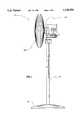
- FIG. 1is a perspective view of the invention.
- FIG. 2is perspective view of an alternative embodiment of the invention incorporating two oscillation motors.
- FIG. 3is a perspective view of an alternative embodiment of the invention wherein the fan motor powers one oscillation mechanism.
- FIGS. 4 and 5are electrical schematic diagrams of, respectively, the embodiments of FIG. 2 and FIG. 3.
- FIG. 6is a perspective detail view of an alternative embodiment of the central column, showing height adjustment.
- FIG. 7is a side elevational, partly cross sectional view of an alternative embodiment of the central column, illustrating a tilting feature.
- FIG. 1is a perspective view of the novel fan 10. Visible in this view are a base 12, vertical column 14, motor 16, and fan blade guard 18. Also seen are oscillation mechanisms which provide the principal novel features.
- FIG. 2illustrates oscillation mechanisms in greater detail.
- An oscillation mechanismis a mechanism which converts an input motion, such as circular or rotary motion from a motor, into oscillation.
- oscillationwill be understood to refer to a repetitive motion causing the fan to discharge air in a repeating pattern of directions.
- Oscillationmay be simple oscillation or complex oscillation.
- a simple oscillationis a motion wherein the fan rotational axis sweeps through an arc, subsequently moving in reverse direction through the same arc, returning to its original position.
- the fan axismoves through a complex motion, there being orthogonal motions responsive to all oscillation units. For example, if one oscillation mechanism moves the fan axis through an arc about one axis of oscillation, and a second oscillation mechanism simultaneously through an arc about an axis of oscillation perpendicular to the first axis of oscillation, then the resultant motion exhibited by the fan will be frustoconical, or a similar complex motion.
- Fan 100 of the embodiment of FIG. 2shows a fan blade 126 mounted to shaft 128 of motor 130.
- Motor 130is supported journaled at 132 on a carriage 134.
- oscillation mechanism 122operates, motor 130 and fan blade 126 oscillate in a vertical plane around a horizontal axis 136.
- Base 112is rigidly secured to column 114, so that motor 130 and fan 126 are held erect relative to base 112.
- Oscillation mechanism 122comprises a tab 138 for secure mounting to motor 130, an oscillation motor 140, a gearbox 142, and a crank 144 having an offset crank arm 146, crank 144 drivingly connected to motor 140 by gearbox 142. It is not absolutely necessary to provide a gearbox. Gearbox 142 is provided where it is necessary to modify motor speeds and torques to drive the crank of an oscillation mechanism at desired speeds.
- Arm 146penetrates a groove 148 formed in a member of carriage 134.
- groove 148accommodates horizontal motion of arm 146.
- motor 130 and all componentsfixed solidly thereto oscillate about axis 136, sweeping through a vertical plane.
- motor 130 and its associated fan 126are oscillated in a vertical plane when oscillation mechanism 122 operates, motor 130 oscillating relative to carriage 134. It is desired that fan 126 also oscillate in a horizontal plane. This is accomplished by causing fan 126, motor 130, and carriage 134 to oscillate as a unit about vertical axis 150.
- Fan 100is supported on base 112 by a column 114.
- Carriage 134is supported at the top of column 114, and is caused to oscillate in the horizontal plane by the following arrangement.
- Column 114has a fixed, immobile portion 152, and a mobile portion 154 rotatably secured to portion 152.
- a joint 156secures portion 154 to portion 152 joint 156 has ball bearings 158 and mutually connected bearing races 160 and 162.
- Bearing race 160is fixed to immobile column portion 152, and is therefore stationary.
- Race 162is fixed to mobile portion 154, and therefore can rotate relative to race 160 and stationary column portion 152.
- a second oscillation mechanism 124causes carriage 134 to oscillate relative to column immobile portion 152.
- Oscillation mechanism 124has components equivalent to those of oscillation mechanism 122. Although the basic principle of operation is similar, orientation of mechanism 124 is modified as shown in this Figure so that oscillation occurs about vertical axis 150.
- Offset crank arm 164 of mechanism 124engages groove 166 of a tab 168 fixed to the immobile portion 152 of column 114.
- Groove 166is arranged to provide vertical accommodation of crank arm 164. No horizontal accommodation is provided by groove 166, so that when crank arm 164 moves, carriage 134 must react by oscillating in a horizontal plane about vertical axis 150.
- fan motor 130 and oscillation mechanisms 122 and 124are each independently controlled.
- Three push button switches 170are provided to control the respective motor for each function.
- Electrical poweris supplied to the respective motors from cord and plug assembly 172 by electrical conductors 174 which preferably pass through the hollow center of column 114.
- the conductorsare sufficiently long and flexible to accommodate oscillation.
- the push buttons of switches 170are located on base 112. This causes the controls of fan 100 to be maintained in a constant location independent of tilting of fan 126 and motor 130.
- fan 200has many components similar to those of fan 100 of FIG. 2.
- the components which are essentially similar in function to those of fan 100include a base 212, column 214, fan 226, motor shaft 228, and motor 230.
- fan 200supporting structure for motor 230 is modified from the design of fan 100. It is contemplated that oscillation in a horizontal plane will be in greater demand than will be oscillation in a vertical plane. Therefore, since fan operation will result in oscillation in this embodiment, fan motor 230 is arranged to provide horizontal oscillation.
- Fan motor 230is supported on a carriage 202, and is journaled at two pivot points, as indicated at 204.
- An oscillation mechanism 206 including gear box 208 and crank 210has an offset crank arm 213 which rides in groove 216 formed in a member fixed to carriage 202.
- Shaft 228 of fan motor 230extends into gear box 208, so that no separate motor is required to operate oscillation mechanism 206. Operation of motor 230 both rotates fan 226 and also oscillates fan 226 about vertical axis 218.
- Carriage 202is pivotally supported on clevis frame 232 at two points, only one point 234 being visible in this view.
- Clevis frame 232is solidly fixed to column 214.
- Oscillation mechanism 222is attached to the bottom side of carriage 202 by a tab or bracket 235, and includes a motor 236, gear box 238, and crank 240.
- Crank 240engages groove 242 formed in a solid member of clevis frame 232. Operation of oscillation mechanism 222 causes carriage 202 to oscillate in a vertical plane about horizontal axis 244.
- Controls in this embodimentare well known capacitance type touch responsive switches, represented by touch pads 246, 248. Unlike a push button, which requires movement to a certain point to operate, touch responsive controls respond merely to contact, which alters capacitance of internal circuit components (not shown).
- the touch responsive switchesenergize a respective motor 230 or 236 through respective conductors 250, 252. Power is supplied to fan 200 by plug and cord assembly 272.
- FIG. 4shows an electrical schematic for fan 100 of FIG. 2.
- a switch 180controls power to fan motor 130 and also to switches 182, 184 controlling oscillation motors 140, 190. This arrangement prevents pointless oscillation should fan motor 130 not be switched on.
- Each switch 180, 182, or 184is controlled by one push button 170 shown in FIG. 2.
- FIG. 5shows an electrical schematic for fan 200 of FIG. 3.
- Touch pad 246(see FIG. 3) activates a three position switch 280 in turn controlling fan motor 230. In one position, fan motor 230 is deenergized. In a second position, indicated at 282, and a third position, indicated at 284, motor winding 286 is energized appropriately to run at different speeds in well known fashion.
- Touch pad 248(see FIG. 3) activates a switch 290 controlling oscillation motor 236 in on-off fashion.
- FIG. 6illustrates optional adjustment of vertical height of fan 10.
- Column 14includes inner and outer telescoping sleeves 20, 22.
- a threaded screw member 24maintains the two sleeves 20, 22 in their selected positions.
- FIG. 7illustrates further features of fan 10 (shown in its entirety in FIG. 1). Tilting of motor 16 (see FIG. 1) with respect to base 12 is enabled by a joint 30. Joint 30 includes a ball 32 and socket 34. Inclined walls 36 formed in socket 34 limits tilting to angle 38 by interfering with column 14. Excessive tilting which might upset balance of fan 10 is thus avoided.
- base 12provides structure for supporting fan 10 (see FIG. 1) on a horizontal environmental surface by providing a flat bottom surface.
- This or equivalent structure, such as legs (not shown),is provided for portable applications of fan 10.
- a suitable bracket (not shown) or other structure for accepting fastenersbe provided.
Landscapes
- Engineering & Computer Science (AREA)
- Mechanical Engineering (AREA)
- General Engineering & Computer Science (AREA)
- Structures Of Non-Positive Displacement Pumps (AREA)
Abstract
Description
Claims (9)
Priority Applications (1)
| Application Number | Priority Date | Filing Date | Title |
|---|---|---|---|
| US08/572,800US5720594A (en) | 1995-12-13 | 1995-12-13 | Fan oscillating in two axes |
Applications Claiming Priority (1)
| Application Number | Priority Date | Filing Date | Title |
|---|---|---|---|
| US08/572,800US5720594A (en) | 1995-12-13 | 1995-12-13 | Fan oscillating in two axes |
Publications (1)
| Publication Number | Publication Date |
|---|---|
| US5720594Atrue US5720594A (en) | 1998-02-24 |
Family
ID=24289403
Family Applications (1)
| Application Number | Title | Priority Date | Filing Date |
|---|---|---|---|
| US08/572,800Expired - Fee RelatedUS5720594A (en) | 1995-12-13 | 1995-12-13 | Fan oscillating in two axes |
Country Status (1)
| Country | Link |
|---|---|
| US (1) | US5720594A (en) |
Cited By (28)
| Publication number | Priority date | Publication date | Assignee | Title |
|---|---|---|---|---|
| US6304719B1 (en)* | 2000-12-18 | 2001-10-16 | Sella Tech Co., Ltd. | Radiant heater with halogen lamp |
| US6321034B2 (en) | 1999-12-06 | 2001-11-20 | The Holmes Group, Inc. | Pivotable heater |
| US6499951B2 (en)* | 2001-06-01 | 2002-12-31 | Huang Chuan Pan | Fan head swinging device |
| US6533551B2 (en) | 2000-09-20 | 2003-03-18 | Kimmy Escobar | Household apparatus |
| US6533548B1 (en)* | 2000-09-11 | 2003-03-18 | Li-Yen Wang Lin | Multi-functional electric fan |
| SG126011A1 (en)* | 2005-03-29 | 2006-10-30 | Chung-Yin Cheng | Electric fan |
| WO2008014641A1 (en)* | 2006-07-25 | 2008-02-07 | Pao-Chu Wang | Electric fan |
| US20080251684A1 (en)* | 2007-04-12 | 2008-10-16 | Ya-Ping Huang | Electric appliance with constant power supplied-bus |
| US20100221114A1 (en)* | 2009-02-28 | 2010-09-02 | Ted Xuan Do | Tornado Fan |
| US20110008190A1 (en)* | 2009-07-08 | 2011-01-13 | Wen Ching Lee | Electric fan with multiple selection of oscillating angles |
| US20110052394A1 (en)* | 2009-09-01 | 2011-03-03 | International Products Group Corp | Conical revolution mechanism |
| US20120039705A1 (en)* | 2009-03-04 | 2012-02-16 | Dyson Technology Limited | Fan assembly |
| US20120156064A1 (en)* | 2010-12-20 | 2012-06-21 | Walter Birdsell | Orbital oscillation fan |
| US8333560B1 (en)* | 2009-06-10 | 2012-12-18 | James Ward | Anti-sudden infant death syndrome baby fan |
| JP2016180566A (en)* | 2015-03-25 | 2016-10-13 | シャープ株式会社 | Blower device |
| CN106411016A (en)* | 2016-10-19 | 2017-02-15 | 珠海格力电器股份有限公司 | Electric fan |
| US9732763B2 (en) | 2012-07-11 | 2017-08-15 | Dyson Technology Limited | Fan assembly |
| US9797414B2 (en) | 2013-07-09 | 2017-10-24 | Dyson Technology Limited | Fan assembly |
| US9845811B1 (en)* | 2016-08-03 | 2017-12-19 | Air Cool Industrial Co., Ltd. | Hanging structure for a wall fan |
| US10006657B2 (en) | 2009-03-04 | 2018-06-26 | Dyson Technology Limited | Fan assembly |
| WO2019000886A1 (en)* | 2017-06-27 | 2019-01-03 | 广东美的环境电器制造有限公司 | Driving assembly for use with fan, and fan having same |
| US10221860B2 (en) | 2009-03-04 | 2019-03-05 | Dyson Technology Limited | Fan assembly |
| US20190134247A1 (en)* | 2017-11-07 | 2019-05-09 | Kingsley Oligie | Fan with air freshening dispenser |
| US10563661B2 (en) | 2017-10-24 | 2020-02-18 | Louis Rogers | Vertically shafted air moving device |
| US20210115932A1 (en)* | 2018-07-30 | 2021-04-22 | Matthews-Gerbar, Ltd. | Wall-Mounted Fan |
| US11162513B2 (en)* | 2018-12-20 | 2021-11-02 | Zhejiang Joyo Electric Appliance Technology Co,. Ltd. | Adjustable stand fan |
| US20220372986A1 (en)* | 2019-12-23 | 2022-11-24 | Gd Midea Environment Appliances Mfg Co., Ltd. | Oscillation Device and Fan |
| US11953017B1 (en) | 2023-08-23 | 2024-04-09 | Shenzhen Qianhai Weilisheng Network Co., Ltd | Hand-held fan |
Citations (19)
| Publication number | Priority date | Publication date | Assignee | Title |
|---|---|---|---|---|
| US2742225A (en)* | 1951-06-11 | 1956-04-17 | Nestor J Guardado | Oscillating fan |
| JPS58162795A (en)* | 1982-03-19 | 1983-09-27 | Sanyo Electric Co Ltd | Electric fan |
| EP0114327A2 (en)* | 1983-01-19 | 1984-08-01 | Carl Schenck Ag | Play-free ball-joint, in particular for test-equipment and joint assembly comprising such ball-joints |
| US4482266A (en)* | 1981-10-23 | 1984-11-13 | Tokico Ltd. | Ball joint |
| JPS6081496A (en)* | 1983-10-11 | 1985-05-09 | Sanyo Electric Co Ltd | Fan |
| JPS61226599A (en)* | 1985-04-01 | 1986-10-08 | Sanyo Electric Co Ltd | Fan |
| US4732539A (en)* | 1986-02-14 | 1988-03-22 | Holmes Products Corp. | Oscillating fan |
| US4743737A (en)* | 1986-02-20 | 1988-05-10 | Tateishi Arthur K | Oscillating louver electric fan heater |
| JPS6466492A (en)* | 1987-09-07 | 1989-03-13 | Matsushita Seiko Kk | Stand type fan |
| US4850804A (en)* | 1986-07-07 | 1989-07-25 | Tatung Company Of America, Inc. | Portable electric fan having a universally adjustable mounting |
| JPH03138488A (en)* | 1989-10-24 | 1991-06-12 | Matsushita Seiko Co Ltd | Turning-up device for electric fan |
| US5163814A (en)* | 1989-06-09 | 1992-11-17 | Caframo Limited | Portable electric fan assembly |
| US5256039A (en)* | 1992-11-09 | 1993-10-26 | Crawford Dale K | Remote controlled moveable fan |
| US5370500A (en)* | 1994-03-14 | 1994-12-06 | Thompson; Jerry E. | Oscillating fan support |
| US5429481A (en)* | 1994-08-24 | 1995-07-04 | Liu; Su-Liang | Angle-adjustable joint for electric fans |
| US5431544A (en)* | 1994-01-03 | 1995-07-11 | Holmes Products Corp. | Tiltable fan assembly |
| US5435696A (en)* | 1993-09-15 | 1995-07-25 | Holmes Products Corp. | Tiltable oscillating fan assembly |
| US5458462A (en)* | 1994-07-27 | 1995-10-17 | Accutek Products Corp. | Swivel mechanism for electrical fan |
| US5556256A (en)* | 1994-07-27 | 1996-09-17 | Shao; Steve | Swivel mechanism for an electrical fan |
- 1995
- 1995-12-13USUS08/572,800patent/US5720594A/ennot_activeExpired - Fee Related
Patent Citations (19)
| Publication number | Priority date | Publication date | Assignee | Title |
|---|---|---|---|---|
| US2742225A (en)* | 1951-06-11 | 1956-04-17 | Nestor J Guardado | Oscillating fan |
| US4482266A (en)* | 1981-10-23 | 1984-11-13 | Tokico Ltd. | Ball joint |
| JPS58162795A (en)* | 1982-03-19 | 1983-09-27 | Sanyo Electric Co Ltd | Electric fan |
| EP0114327A2 (en)* | 1983-01-19 | 1984-08-01 | Carl Schenck Ag | Play-free ball-joint, in particular for test-equipment and joint assembly comprising such ball-joints |
| JPS6081496A (en)* | 1983-10-11 | 1985-05-09 | Sanyo Electric Co Ltd | Fan |
| JPS61226599A (en)* | 1985-04-01 | 1986-10-08 | Sanyo Electric Co Ltd | Fan |
| US4732539A (en)* | 1986-02-14 | 1988-03-22 | Holmes Products Corp. | Oscillating fan |
| US4743737A (en)* | 1986-02-20 | 1988-05-10 | Tateishi Arthur K | Oscillating louver electric fan heater |
| US4850804A (en)* | 1986-07-07 | 1989-07-25 | Tatung Company Of America, Inc. | Portable electric fan having a universally adjustable mounting |
| JPS6466492A (en)* | 1987-09-07 | 1989-03-13 | Matsushita Seiko Kk | Stand type fan |
| US5163814A (en)* | 1989-06-09 | 1992-11-17 | Caframo Limited | Portable electric fan assembly |
| JPH03138488A (en)* | 1989-10-24 | 1991-06-12 | Matsushita Seiko Co Ltd | Turning-up device for electric fan |
| US5256039A (en)* | 1992-11-09 | 1993-10-26 | Crawford Dale K | Remote controlled moveable fan |
| US5435696A (en)* | 1993-09-15 | 1995-07-25 | Holmes Products Corp. | Tiltable oscillating fan assembly |
| US5431544A (en)* | 1994-01-03 | 1995-07-11 | Holmes Products Corp. | Tiltable fan assembly |
| US5370500A (en)* | 1994-03-14 | 1994-12-06 | Thompson; Jerry E. | Oscillating fan support |
| US5458462A (en)* | 1994-07-27 | 1995-10-17 | Accutek Products Corp. | Swivel mechanism for electrical fan |
| US5556256A (en)* | 1994-07-27 | 1996-09-17 | Shao; Steve | Swivel mechanism for an electrical fan |
| US5429481A (en)* | 1994-08-24 | 1995-07-04 | Liu; Su-Liang | Angle-adjustable joint for electric fans |
Cited By (38)
| Publication number | Priority date | Publication date | Assignee | Title |
|---|---|---|---|---|
| US6321034B2 (en) | 1999-12-06 | 2001-11-20 | The Holmes Group, Inc. | Pivotable heater |
| US6533548B1 (en)* | 2000-09-11 | 2003-03-18 | Li-Yen Wang Lin | Multi-functional electric fan |
| US6533551B2 (en) | 2000-09-20 | 2003-03-18 | Kimmy Escobar | Household apparatus |
| US6304719B1 (en)* | 2000-12-18 | 2001-10-16 | Sella Tech Co., Ltd. | Radiant heater with halogen lamp |
| US6499951B2 (en)* | 2001-06-01 | 2002-12-31 | Huang Chuan Pan | Fan head swinging device |
| SG126011A1 (en)* | 2005-03-29 | 2006-10-30 | Chung-Yin Cheng | Electric fan |
| WO2008014641A1 (en)* | 2006-07-25 | 2008-02-07 | Pao-Chu Wang | Electric fan |
| US20080251684A1 (en)* | 2007-04-12 | 2008-10-16 | Ya-Ping Huang | Electric appliance with constant power supplied-bus |
| US20100221114A1 (en)* | 2009-02-28 | 2010-09-02 | Ted Xuan Do | Tornado Fan |
| US9651025B2 (en)* | 2009-02-28 | 2017-05-16 | Ted Xuan Do | Tornado fan |
| US10221860B2 (en) | 2009-03-04 | 2019-03-05 | Dyson Technology Limited | Fan assembly |
| US20120039705A1 (en)* | 2009-03-04 | 2012-02-16 | Dyson Technology Limited | Fan assembly |
| US20120045316A1 (en)* | 2009-03-04 | 2012-02-23 | Dyson Technology Limited | Fan assembly |
| US20120045315A1 (en)* | 2009-03-04 | 2012-02-23 | Dyson Technology Limited | Fan assembly |
| US10006657B2 (en) | 2009-03-04 | 2018-06-26 | Dyson Technology Limited | Fan assembly |
| US8348596B2 (en)* | 2009-03-04 | 2013-01-08 | Dyson Technology Limited | Fan assembly |
| US8348597B2 (en)* | 2009-03-04 | 2013-01-08 | Dyson Technology Limited | Fan assembly |
| US8469655B2 (en)* | 2009-03-04 | 2013-06-25 | Dyson Technology Limited | Fan assembly |
| US8333560B1 (en)* | 2009-06-10 | 2012-12-18 | James Ward | Anti-sudden infant death syndrome baby fan |
| US20110008190A1 (en)* | 2009-07-08 | 2011-01-13 | Wen Ching Lee | Electric fan with multiple selection of oscillating angles |
| US8506265B2 (en)* | 2009-07-08 | 2013-08-13 | Wen Ching Lee | Electric fan with multiple selection of oscillating angles |
| US20110052394A1 (en)* | 2009-09-01 | 2011-03-03 | International Products Group Corp | Conical revolution mechanism |
| US20120156064A1 (en)* | 2010-12-20 | 2012-06-21 | Walter Birdsell | Orbital oscillation fan |
| US9732763B2 (en) | 2012-07-11 | 2017-08-15 | Dyson Technology Limited | Fan assembly |
| US9797414B2 (en) | 2013-07-09 | 2017-10-24 | Dyson Technology Limited | Fan assembly |
| JP2016180566A (en)* | 2015-03-25 | 2016-10-13 | シャープ株式会社 | Blower device |
| US9845811B1 (en)* | 2016-08-03 | 2017-12-19 | Air Cool Industrial Co., Ltd. | Hanging structure for a wall fan |
| CN106411016A (en)* | 2016-10-19 | 2017-02-15 | 珠海格力电器股份有限公司 | Electric fan |
| CN106411016B (en)* | 2016-10-19 | 2018-11-27 | 珠海格力电器股份有限公司 | electric fan |
| WO2019000886A1 (en)* | 2017-06-27 | 2019-01-03 | 广东美的环境电器制造有限公司 | Driving assembly for use with fan, and fan having same |
| US11313375B2 (en) | 2017-06-27 | 2022-04-26 | Gd Midea Environment Appliances Mfg Co., Ltd. | Driving assembly for use with fan, and fan having same |
| US10563661B2 (en) | 2017-10-24 | 2020-02-18 | Louis Rogers | Vertically shafted air moving device |
| US20190134247A1 (en)* | 2017-11-07 | 2019-05-09 | Kingsley Oligie | Fan with air freshening dispenser |
| US20210115932A1 (en)* | 2018-07-30 | 2021-04-22 | Matthews-Gerbar, Ltd. | Wall-Mounted Fan |
| US11162513B2 (en)* | 2018-12-20 | 2021-11-02 | Zhejiang Joyo Electric Appliance Technology Co,. Ltd. | Adjustable stand fan |
| US20220372986A1 (en)* | 2019-12-23 | 2022-11-24 | Gd Midea Environment Appliances Mfg Co., Ltd. | Oscillation Device and Fan |
| US12110899B2 (en)* | 2019-12-23 | 2024-10-08 | Gd Midea Environment Appliances Mfg Co., Ltd. | Oscillation device and fan |
| US11953017B1 (en) | 2023-08-23 | 2024-04-09 | Shenzhen Qianhai Weilisheng Network Co., Ltd | Hand-held fan |
Similar Documents
| Publication | Publication Date | Title |
|---|---|---|
| US5720594A (en) | Fan oscillating in two axes | |
| US20040022631A1 (en) | Tower fan | |
| CN113775887A (en) | Cloud deck, control method thereof and unmanned aerial vehicle | |
| US5957745A (en) | Gyroscopic figurine | |
| CN112306098A (en) | Spirit level, support device and method for adjusting the level of the bearing surface of the support device surface | |
| US5458462A (en) | Swivel mechanism for electrical fan | |
| US4539913A (en) | Work table | |
| CN111059487A (en) | A professional desk lamp | |
| CA1075058A (en) | Electrically controlled rear-view mirror | |
| CN206943057U (en) | The drive assembly and oscillating fan of oscillating fan | |
| JP2001238096A (en) | Operating device for three-axis driven photographing device | |
| JPH07328233A (en) | Body feeling simulation game machine | |
| CN112413366A (en) | Self-adaptive fixing device of electronic equipment | |
| JPH0799593A (en) | Electric pan head for camera | |
| JPH0396697A (en) | Portable electric fan | |
| JPH1032771A (en) | Display device with rotation / tilt mechanism | |
| JP3678576B2 (en) | Horizontal / tilt adjustment device | |
| JPH04352982A (en) | Bodily sensitively movable game machine | |
| KR0145782B1 (en) | Humidifier with rotating spray nozzle | |
| JP3048922U (en) | Fan with adjustable swing angle | |
| KR200175670Y1 (en) | Fans with wind direction switch | |
| JPS63154893A (en) | Fan swing device | |
| US12024373B1 (en) | System to move objects in a circle | |
| KR102683149B1 (en) | Rotation control apparatus and fan including the same | |
| JP2000065288A (en) | Universal attitude control device |
Legal Events
| Date | Code | Title | Description |
|---|---|---|---|
| AS | Assignment | Owner name:HOLMES PRODUCTS CORP., MASSACHUSETTS Free format text:ASSIGNMENT OF ASSIGNORS INTEREST;ASSIGNOR:SNOW, DANIEL;REEL/FRAME:008428/0220 Effective date:19960528 Owner name:HOLMES PRODUCTS, CORP, MASSACHUSETTS Free format text:;ASSIGNOR:SNOW, DANIEL;REEL/FRAME:008396/0093 Effective date:19960528 | |
| AS | Assignment | Owner name:BANKBOSTON, N.A., MASSACHUSETTS Free format text:SECURITY AGREEMENT;ASSIGNOR:HOLMES PRODUCT CORPORATION;REEL/FRAME:008848/0325 Effective date:19971126 | |
| AS | Assignment | Owner name:BANKBOSTON, N.A. AS AGENT, MASSACHUSETTS Free format text:FIRST SUPPLEMENTAL PATENT COLLATERAL ASSIGNMENT AND SECURITY AGREEMENT;ASSIGNOR:HOLMES PRODUCTS CORP.;REEL/FRAME:009866/0312 Effective date:19990205 | |
| REMI | Maintenance fee reminder mailed | ||
| LAPS | Lapse for failure to pay maintenance fees | ||
| STCH | Information on status: patent discontinuation | Free format text:PATENT EXPIRED DUE TO NONPAYMENT OF MAINTENANCE FEES UNDER 37 CFR 1.362 | |
| FP | Lapsed due to failure to pay maintenance fee | Effective date:20020224 | |
| AS | Assignment | Owner name:HOLMES PRODUCTS CORP., MASSACHUSETTS Free format text:RELEASE OF SECURITY INTEREST;ASSIGNOR:FLEET NATIONAL BANK;REEL/FRAME:015215/0041 Effective date:20040506 |