US5720589A - Swivel mounted container holding device - Google Patents
Swivel mounted container holding deviceDownload PDFInfo
- Publication number
- US5720589A US5720589AUS08/596,648US59664896AUS5720589AUS 5720589 AUS5720589 AUS 5720589AUS 59664896 AUS59664896 AUS 59664896AUS 5720589 AUS5720589 AUS 5720589A
- Authority
- US
- United States
- Prior art keywords
- arm
- grabber
- arm segment
- segment
- container
- Prior art date
- Legal status (The legal status is an assumption and is not a legal conclusion. Google has not performed a legal analysis and makes no representation as to the accuracy of the status listed.)
- Expired - Lifetime
Links
Images


Classifications
- B—PERFORMING OPERATIONS; TRANSPORTING
- B65—CONVEYING; PACKING; STORING; HANDLING THIN OR FILAMENTARY MATERIAL
- B65F—GATHERING OR REMOVAL OF DOMESTIC OR LIKE REFUSE
- B65F3/00—Vehicles particularly adapted for collecting refuse
- B65F3/02—Vehicles particularly adapted for collecting refuse with means for discharging refuse receptacles thereinto
- B65F3/04—Linkages, pivoted arms, or pivoted carriers for raising and subsequently tipping receptacles
- B65F3/048—Linkages
- B—PERFORMING OPERATIONS; TRANSPORTING
- B65—CONVEYING; PACKING; STORING; HANDLING THIN OR FILAMENTARY MATERIAL
- B65F—GATHERING OR REMOVAL OF DOMESTIC OR LIKE REFUSE
- B65F3/00—Vehicles particularly adapted for collecting refuse
- B—PERFORMING OPERATIONS; TRANSPORTING
- B65—CONVEYING; PACKING; STORING; HANDLING THIN OR FILAMENTARY MATERIAL
- B65F—GATHERING OR REMOVAL OF DOMESTIC OR LIKE REFUSE
- B65F3/00—Vehicles particularly adapted for collecting refuse
- B65F3/02—Vehicles particularly adapted for collecting refuse with means for discharging refuse receptacles thereinto
- B65F3/04—Linkages, pivoted arms, or pivoted carriers for raising and subsequently tipping receptacles
- B65F3/041—Pivoted arms or pivoted carriers
- B65F3/046—Pivoted arms or pivoted carriers with additional means for assisting the tipping of the receptacle after or during raising
- B—PERFORMING OPERATIONS; TRANSPORTING
- B65—CONVEYING; PACKING; STORING; HANDLING THIN OR FILAMENTARY MATERIAL
- B65F—GATHERING OR REMOVAL OF DOMESTIC OR LIKE REFUSE
- B65F3/00—Vehicles particularly adapted for collecting refuse
- B65F3/24—Vehicles particularly adapted for collecting refuse with devices for unloading the tank of a refuse vehicle
- B65F3/26—Vehicles particularly adapted for collecting refuse with devices for unloading the tank of a refuse vehicle by tipping the tank
- B—PERFORMING OPERATIONS; TRANSPORTING
- B65—CONVEYING; PACKING; STORING; HANDLING THIN OR FILAMENTARY MATERIAL
- B65F—GATHERING OR REMOVAL OF DOMESTIC OR LIKE REFUSE
- B65F3/00—Vehicles particularly adapted for collecting refuse
- B65F3/02—Vehicles particularly adapted for collecting refuse with means for discharging refuse receptacles thereinto
- B65F2003/0223—Vehicles particularly adapted for collecting refuse with means for discharging refuse receptacles thereinto the discharging means comprising elements for holding the receptacle
- B65F2003/023—Gripper arms for embracing the receptacle
- B—PERFORMING OPERATIONS; TRANSPORTING
- B65—CONVEYING; PACKING; STORING; HANDLING THIN OR FILAMENTARY MATERIAL
- B65F—GATHERING OR REMOVAL OF DOMESTIC OR LIKE REFUSE
- B65F3/00—Vehicles particularly adapted for collecting refuse
- B65F3/02—Vehicles particularly adapted for collecting refuse with means for discharging refuse receptacles thereinto
- B65F2003/0263—Constructional features relating to discharging means
- B65F2003/0273—Constructional features relating to discharging means capable of rotating around a vertical axis
Definitions
- This inventionrelates generally to material handling equipment and, more particularly, to a lifting device attached to a refuse vehicle for handling containers during collection efforts.
- Mechanized material handling devicesoften include a container holder or grasping device connected to an arm which is connected to a base, such as a vehicle.
- the arm and grasping deviceare operated to engage a container of interest, lift and dump the container into a receiving hopper in the vehicle.
- U.S. Pat. No. 5,391,039issued to Holtom, which describes a refuse loader arm including a lift limb and a reach limb articulated to one another at a pivot point.
- the lift limbis vertically pivotally attached at one end to a refuse vehicle and the reach limb is articulated at its other end to a bin grasping assembly which is held at a constant angle to the lift limb by a parallelogram linkage.
- the lift limb and the reach limbpivot in a common plane to reach out and grasp the container of interest and lift and dump the container. 0f course, the vehicle must be positioned directly alongside such that the container is aligned with the pivoting plane of the arm.
- 5,330,308issued to Armando et al., describes a refuse container loading device including a tubular support attached to a refuse vehicle, operable to pivot in a horizontal plane.
- a telescoping arm that pivots verticallyis attached to the base and to a bin grasping device that is able to pivot vertically and swivel horizontally.
- U.S. Pat. No. 4,175,903issued to Carson, describes an apparatus for picking up containers wherein a boom arm is attached to a platform which is pivotally attached to a refuse vehicle for rotating in a generally horizontal plane.
- the boom armis pivotally attached to the platform for pivoting vertically to raise and dump a container.
- a pick-up armis provided to grasp the container and is attached to the boom arm with the ability to rotate in essentially a horizontal plane.
- a principle object of the inventionthen is to provide an improved lifting device for handling objects or containers of interest.
- Another object of the inventionis to provide a relatively simple lifting device attached to a vehicle which eliminates the need for precise positioning of the vehicle.
- Still another object of the inventionis to provide a lifting device which includes an articulated arm disposed to pivot in one plane and rotatably attached to the vehicle for swiveling in another plane.
- Yet another object of the inventionis to provide a lifting device which operates in two planes and includes a bin grasping device.
- a further object of the inventionis to provide a lifting device including an articulated arm disposed to pivot in one plane and rotatably attached to a refuse vehicle for pivoting in another plane and including a grasping device pivotally attached to the articulated arm for pivoting in the same plane as the articulated arm.
- a lifting deviceincluding a swivel mount or turret which rotates in a generally horizontal plane, i.e., parallel to the deck of a vehicle on which it is mounted such as a refuse vehicle and an articulated arm connected to the swivel mount.
- the swivel mountincludes a housing which rotates about a shaft connected to one or more support plates which are, in turn, attached to the vehicle.
- the articulated armis attached to the housing and includes first and second arm members joined or articulated to one another, at one end.
- the first arm memberis pivotally attached at a second end to an arm pivot support attached to the housing and the second arm member has a free end which carries a gripping or grasping mechanism.
- the articulated armpivots in a generally vertical plane to provide a lift and dump function.
- the swivel mountincludes a base plate attached to the frame of a vehicle and upper and lower parallel pivot plates attached to the base plate and carrying a shaft therebetween.
- the housing memberis engaged on the shaft and a lever arm is attached to the housing member.
- the lever arm or crankis connected to the rod end of a hydraulic cylinder attached to the frame or a frame extension of the vehicle and which reciprocates to rotate the housing member.
- the housing memberrotates in a plane parallel to the deck or frame of the vehicle.
- the arm base pivotis attached to the housing member such that the articulated arm is disposed to pivot in a generally vertical plane essentially perpendicular to the plane of rotation of the swivel mount.
- the grasping deviceis pivotally connected to the second or outer arm member of the articulated arm so as to pivot in the same plane as the articulated arm.
- One embodiment of the grasping devicefurther uses a plurality of opposed digits which may be articulated and which open and close to release and capture a standing container of any cross sectional shape.
- the digits of the grasping deviceare in an "as stowed" or open position and the articulated arm is extended to move the grasping device toward the container of interest.
- the swivel mountis pivoted to move the grasping device into engagement with the container of interest.
- the grasping deviceis operated to a closed position to grab the container and the articulated arm is operated generally vertically to lift and tip or invert the container and empty the contents into a receiving hopper of the vehicle.
- the swivel mountneed not be operated since the arm and grasping device tilt the container above the swivel mount regardless of the selective rotational position of the swivel mount.
- the swivel mountincludes a rotary actuator, such as a rack and pinion or beveled gears including a worm gear and planetary gear or other device such as a rotary hydraulic actuator, to pivot the housing member about a shaft which is carried by a single lower pivot plate attached to a base plate which, in turn, is fixed to the frame.
- the articulated arm and grasping deviceare attached to the housing member connected to pivot in a generally vertical plane which is perpendicular to the plane of rotation of the housing member.
- One grasping device suitable for any embodiment of the inventionhas a pair of spaced, opposed arms or digits pivotally connected to a central support member.
- the armsare shaped to fit around containers of a plurality of different shapes, including curved, rectangular, hexagonal and others.
- the armsare pivoted between an open or retracted position in a closed or grasping position by fluid-operated actuators, such as hydraulic cylinders.
- the armsmay be either single or plural member type arms having curvilinear shape and in one embodiment shown, the plural member or articulated dual arm embodiment is described in which each arm has an inner member pivotally connected at one end to a common support member and an outer member pivotally connected to a corresponding inner member.
- the fluid-operated actuatorssuch as double acting hydraulic cylinders, are pivotally connected between each outer member and the common support member.
- the pivot points of the armsare closer together and closer to the container of interest than those of the actuators on the common support to provide leverage and allow the arms to grasp the container of interest on the power stroke of the double acting hydraulic cylinders.
- the lifting device of the present inventionmay be mounted on other vehicles including dump trucks or used without reference to a vehicle as a stationary loader.
- the swivel mountmay be attached to either the frame (chassis) of the vehicle or to a material receiving body of the vehicle, such as the storage body of the refuse truck or dump body of a dump truck. In this configuration, the lifting device is lifted with the storage body or dumping body to a raised position during the dumping operations.
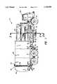
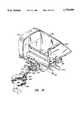
- FIG. 1is a side elevational view of a refuse collection vehicle equipped with a lifting device according to the invention
- FIG. 2depicts an enlarged view partially in section taken substantially along lines 2--2 of FIG. 1 and showing one type of hydraulically operated swivel mount;
- FIG. 3is a partial top view of the refuse collection vehicle of FIG. 1 showing the hydraulic cylinder and lifting device in dashed lines;
- FIG. 4is a view similar to FIG. 3 showing the articulated arm extended and the swivel mount in three different positions;
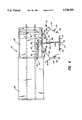
- FIG. 5is a view of the refuse collection vehicle of FIG. 1 taken substantially along lines 5--5 of FIG. 1 showing the articulated arm in the stowed position in bold lines and in the grasping and dumping positions in dashed lines;
- FIG. 6is a top view of the grasping device in the open as stowed position
- FIG. 7is a top view of the grasping device in the closed or grasping position
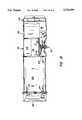
- FIG. 8is an enlarged view similar to that of FIG. 5 showing a rotatory swivel actuator
- FIG. 9is a side elevational view of a refuse collection vehicle similar to that of FIG. 1 equipped with a more detailed container lifting device;
- FIG. 10is a top view of the refuse collection vehicle of FIG. 9 with the container handling device in a stowed position;
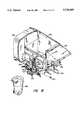
- FIG. 11depicts an enlarged view, partially in section, taken substantially along lines 11--11 of FIG. 9;
- FIG. 12is a fragmentary perspective view of the embodiment of FIG. 9 showing the container handling system in the stowed position;
- FIG. 13Ais a fragmentary perspective view similar to that of FIG. 12 showing the arm extension and grabber seizing functions with respect to the container handling system as it addresses a curbside container;
- FIG. 13Bis an enlarged fragmentary perspective view illustrating the details of the container handling mechanism of FIG. 13A;
- FIG. 14is a view similar to that of FIG. 13A showing a container (in phantom) as having been seized by the grabber;
- FIG. 15is a view similar to that of FIG. 11 depicting the arm retracted and the grabber holding the seized container in preparation for dumping and tipping;
- FIG. 16is a view similar to that of FIG. 15 illustrating the seized container in the raised, inverted or tipped posture.
- the swivel or rotary mounted lifting device of the present inventionis particularly applicable to load refuse collection vehicles. It is characterized by a swivel or rotary mount or joint in combination with an articulated lift and dump arm having a container grasping device.
- the swivel or rotary mountenables a connected lift arm and grasping device or grabber to move extensively fore and aft of the mount to thereby enable the system to address containers at a variety of locations alongside the vehicle.
- the swivel mountmay include a linear actuator and lever arm or a rotary actuator for pivoting the swivel.
- the swivel mount basemay be adapted to be attached to the frame or chassis, or to the body of any refuse vehicle.
- the swivel mounted lifting deviceis attached to the frame of a side loading refuse vehicle.
- the side loading refuse vehiclemay have an offset or recessed hopper portion but this is not required to accommodate the swivel mount system.
- the hoppermay be recessed on the side opposite the swivel mounted lifting device to accommodate a second loading mechanism. This may be a manually loaded bucket with a mechanized dumping system. Vehicles of this type are described and shown in patent application Ser. No. 08/508,384, filed Jul. 31, 1995, titled REFUSE COLLECTION SYSTEM, the disclosure of which is hereby incorporated herein by reference for any necessary purposes.
- a chassis or frame mounted swivelling lifting deviceincludes a swivel mount, generally at 20, which is attached to a main frame or chassis member 22 of a side loading refuse vehicle 24.
- the swivel mount 20is attached to the frame member 22 underneath a refuse receiving or charging hopper 26 which includes a top opening 28 for receiving refuse.
- a hinged or pivoting lift arm, generally at 30,is pivotally connected to the swivel mount 20 and a refuse container holder or grabber, generally at, 32 is pivotally attached to the lift arm 30.
- the swivel mountenables the position of the lift arm 30 and container holder 32 to be adjusted back and forth along the length of the refuse vehicle 24 to accommodate the position of a container of interest.
- the grabber 32 and lift arm 30cooperate to empty refuse containers into charging hopper 26 through opening 28.
- the refuse vehicle 24need not be aligned precisely with the container of interest for grasping and tilting.
- the refuse vehicle 24includes the usual cab 34 and wheels 36 which carry a storage body 38 connected to a charging hopper 26 and pivotally attached to the frame members 22 as at 40.
- Storage body 38includes a tailgate 42 which is pivotally attached by a pair of vertically displaceable hinges, one of which appears at 44, mounted at the top of the storage body 38.
- the tailgate 42is operated between an open and a closed position by a pair of hydraulic cylinders, one of which is shown at 46, which are pivotally attached to the tailgate 42, as at 48, and to the storage body 38 as at 50.
- Side latches 52are provided for latching the tailgate 42 to the storage body 38 in a well-known matter.
- the storage bodyis designed to tilt in conjunction with the opening of the tail gate to discharge refuse. Tilting is accomplished by a pair of side mounted hydraulic lift cylinders 54 that are pivotally attached to the frame by structural member 56 at 58 and to the storage body 38 at 60.
- the swivel mount 20includes a base plate 70 fixed to frame member 22.
- Upper and lower swivel mount pivot plates 72 and 74are attached, as by welding, to the base plate 70.
- a stationary shaft 76is attached between the upper and lower pivot plates 72 and 74 and the swivel mount turns on a bearing housing 80 that rotates about the shaft 76 on spaced roller bearings 82 and 84.
- An arm mounting plate or member 78is attached to the bearing housing 80. The arm mounting member 78 pivots as bearing housing 80 is rotated about shaft 76.
- the rotation of the housing 80 and the arm mounting member 78is accomplished by a system including a lever or crank arm 86 attached to the bearing housing 80 and pivotally attached at 88 to a linear operator such as a hydraulic cylinder 90 (FIG. 3) which is pivotally attached at 92 to a plate member 94.
- Hydraulic cylinder 90operates crank 86 to rotate or pivot bearing housing 80 and the arm pivot member about the shaft 76.
- Plate members 96 and 98are attached between the base plate 70 and the upper and lower pivot plates 72 and 74 to add structural support.
- the lift arm 30includes a pair of connected generally vertically pivotal articulated members including a first or inner lift arm member 100 pivotally attached to the lift arm mounting member 78 at 102 and a second or outer lift arm member 104 pivotally attached to the first lift arm member 100 at 106.
- the refuse can holder or grabber 32is pivotally attached to the outer lift arm member 104 at 108.
- the lift arm 30may be operated by hydraulic cylinders or rotary actuators at the pivots 102, 106, and 108 to extend the lift arm 30 for grasping the container of interest and lifting and dumping the container into the refuse charging hopper 26.
- the lift arm 30is not limited to the embodiment shown and may be any suitable lift arm attached to the bearing housing 80.
- Extending and retracting hydraulic cylinder 90rotates or pivots the lift arm 30 about shaft 76 to position the container grabber 32 along the length of the refuse vehicle 24.
- the swivel cylinder 90 and the lift arm 30 and container grabber or grasping device 32cooperate to grasp a container of interest, lift, invert, and dump it into the refuse charging hopper 26 through opening 28.
- the lift arm 30In a stowed position, as shown in FIGS. 1 and 3 and depicted in FIG. 5 in solid lines, the lift arm 30 is pulled in next to the hopper 26 and the container grabber 32 is retracted to the open (flat) position. This holds the container grabber or grasping device 32 substantially in line with one side of the storage body 38.
- FIGS. 4-7Details of one grasping device are shown in FIGS. 4-7. Addition detail and embodiments may be had by consulting U.S. patent application Ser. No. 08/342,752, entitled CONTAINER HOLDING AND LIFTING DEVICE, filed Nov. 21, 1994 and assigned to the same assignee as the present application, the disclosure of which is hereby incorporated by referenced herein for any necessary purpose.
- the refuse container grabber 32itself includes first and second opposed compound arms 110 and 112 which are pivotally attached to support member 114 which, in turn, is pivotally attached to outer lift arm member 104 at 108.
- the opposed arms 110 and 112are operated by hydraulic cylinders or rotary actuators between an open or stowed position (FIG. 6) and a closed or grasping position (FIG. 7).
- Arms 110 and 112include inner members 140 and 142 pivotally connected to the support member 114 at first support pivot points 144 and 146 and pivotally connected to outer members 148 and 150 at arm member pivot points 152 and 154.
- Linear actuators 156 and 158are pivotally connected to the support member 114 at second support pivot points 160 and 162 and to outer members 148 and 150 at offset pivot points 164 and 166.
- Hydraulic cylinder actuators 156 and 158are expanded to accomplish the gripping or grasping operation.
- Inner members 140 and 142close around a container of interest and outer members 148 and 150 pivot about points 152 and 154 to contact and grasp the container of interest pulling it toward supporting member 114.
- Contact rollers 170 and 172 carried by the outer members 148 and 150operate to urge containers of a plurality of different shapes toward and securely hold the containers against the support member 114.
- Hydraulic cylinder actuators 156 and 158are retracted to reverse this sequence and open the grasping device 32 to the position shown in FIG. 6.
- the support member 114has a rounded centered recess surface at 174 to receive a rounded or circular container 176 flanked by a pair of flat surface segments 178 and 180 which accommodate a rectangular container 182.
- the grasping device 32holds either a rounded container or a rectangular container 182 with equal dexterity.
- Inner members 140 and 142have first corresponding and opposed shaped inner surfaces 184 and 186 and outer members 148 and 150 have second corresponding and opposed shaped inner surfaces 188 and 190 to fit around the corners of a rectangular container 182. Together, inner members 140 and 142 and outer members 148 and 150 produce a smooth rounded surface for holding a rounded container 176.
- Round and rectangular shaped containersare representative of the diverse variety of shapes the grasping device can successfully engage.
- Other shapes that can be graspedinclude hexagonal and oblong shapes.
- the hydraulic cylinder-operated swivel mount support and operating systemis replaced by a rotary actuator, indicated by the numeral 120, which may be any type of rotary actuator including rotary hydraulic actuator, a rotating piston, planetary and worm gear arrangement, rack and pinion, etc.
- the rotary actuator 120is attached to a pivot plate 122 which is carried by a base plate 124 which, in turn, is attached to frame member 22.
- An actuator support plate 126is attached to the base plate and additional support is provided by member 127.
- the rotary actuator 120carries lever arm mounting plate member 78 and rotates about 128 to pivot the lift arm 30 and container grabber 32 along the length of the vehicle 24.
- the lift arm 30 and container grasping device 32are aligned with a container using the rotary actuator 120 to grasp and dump containers into the hopper 26.
- the refuse received in the charging hopper 26, of course,is moved and packed through the hopper into the storage body 38 in a well known manner.
- This systemmay employ a packing ram or rotary packer, for example.
- the lift arm 30In the stowed position, as shown in FIG. 8, the lift arm 30 is retracted close to the hopper 26 and the container grabber or grasping device 32 is left in the open position.
- the container grasping device 32 and lift arm 30are essentially in line with the side 130 of the storage body 38. In this manner the loading device does not protrude beyond the side of the storage body when the truck is operated between pick-up stops. Thus, the system does not necessitate a deeply recessed charging hopper 26.
- FIGS. 9 and 10depict a chassis or frame mounted swiveling container handling device that includes a swivel mount, generally 220, which is attached to one of two main frame or chassis members 222 and 222a (FIG. 11) of a side loading refuse vehicle 224.
- the swivel mount 220is attached to the frame member 222 by a heavy plate member 225 fixed underneath the side of recessed or offset refuse receiving or charging hopper 226.
- the hopperincludes a top opening 228 dedicated to receive refuse for compacting.
- the hinged, articulated pivoting lift arm systemis shown generally at 230 and is pivotally connected between swivel mount 220 at a fixed end and a refuse container seizing and holding system or grabber system, generally at 232 attached to the free end thereof.
- the extendable arm and swivel mount combinationenables the position of the lift arm 230 and container holder 232 to be adjusted laterally and back and forth along the length of the refuse vehicle 224 to accommodate handling a container of interest anywhere within a relatively extensive range.
- the grabber system 232 and handling arm 230cooperate to approach, seize, lift, empty, and return refuse containers into charging hopper 226 through opening 228.
- curbside refuse containersneed not be aligned at a particular spot or be particularly close to the truck so long as they are in the range of the extendable arm.
- the refuse vehicle 224 of FIG. 9 as with that of FIG. 1includes a cab 234 and a storage body 236 connected to receive material from charging hopper 226 carried on a common sub-frame 238 which, in turn, may be pivotally attached to heavy chassis frame members 222, 222a, as at 240.
- Storage body 236includes a tailgate 242 which is pivotally carried by a pair of hinges, one of which appears at 244, mounted at the top of the storage body 236.
- the tailgate 242is operated between an open and a closed position by a pair of hydraulic cylinders, one of which is shown at 246, which are pivotally attached to the tailgate 242, as at 248, and to the storage body 236, as at 250.
- Tailgate 242latching tailgate 242 to the storage body 236 in a well-known manner.
- the tailgateis designed to open in conjunction with the tilting of the storage body to discharge refuse. Tilting is accomplished by a pair of spaced side mounted hydraulic lift cylinders, one of which appears at 254, that are pivotally attached between the frame by a heavy lug or gusset member 256 at 258 and to the storage body sub-frame 238 at 260.
- a cab protectoris shown at 262 and the entire system is supported by a plurality of wheels 264.
- the swivel mount 220includes heavy base plate 225 affixed to frame member 222.
- An arm base pivot support structureis shown at 266 including spaced upper and lower flanges 268 and 270 through which a pivot shaft 272 is journaled for rotation on spaced bearings as at 274.
- An operable swivel arm or connecting link 278is keyed to the pivot shaft 272 and the base pivot cylinder 280 is connected between the free end of the swivel operating link 278 and a wrist pin mount at 282.
- the articulated arm systemis mounted between a pair of spaced heavy gauge arm mounting plates or lugs 284 and 286 (FIG. 13A). Extension and retraction of the cylinder 280 rotates the shaft 272 thereby pivoting the dual plate arm support system about forward and aft in relationship to the vehicle chassis.
- the container handling system itselfis best presented with reference to FIGS. 13A-16.
- the articulated arm 230includes inner and outer segments 290 and 292 generally sequentially and vertically pivotally connected at a central joint 294.
- the segment 292carries the grabber system 232.
- the joints of the system, particularly those of the articulated arm,may be provided with resilient bushings to cushion the operation of the system and increase the life of the mechanical joints. These may be of a rubber compound or other durable resilient material of a durometer to reduce shock yet not affect mechanical joint performance.
- the segmented arm 230is operated by a pair of linear actuators, preferably hydraulic cylinders, including an upper or reach controlling cylinder 296 and a lower or lift cylinder or lift/tipping or dumping cylinder 298, each being mounted with a free end and a pivotally connected fixed end.
- the actuator 296is pivotally connected between a wrist pin pivot joint 300 connected between mounting plates 284 and 286 and a second wrist pin type pivot joint 302 connected between spaced lugs 304 and 306 fixed at the outer end of the segment 290.
- the lift cylinder or actuator 298is also connected at its fixed end pivotally between the mounting plates 284 and 286 at 308.
- the free end of the actuator 298is connected to a common pin member 309 that joins the common joint of spaced pairs of arcuate linkage elements connected between the arm elements 290 and 292 and on either side thereof, one pair of which is shown at 310 and 312.
- Element 310is connected to arm segment 292 at 314 and element 312 to segment 290 at 316.
- a grabber mounting and pivot segment 318pivotally connects the grabber system 232 to the free end of arm segment 292 at 320.
- a pair of spaced operating following rods or linkage barsone of which is shown at 321, are leveraged between an offset connection to a connecting link segment 318 at 323 and a common connection at the linkage element arm segment joint 316.
- the grabber 232includes opposed digits or compound jaw elements having inner segments 322 and 324 flanked by outer segments 326 and 328.
- the inner segments 322 and 324are pivotally connected to a base element 330 at 332 and 334, respectively, and outer segments 326 and 328 likewise are pivotally connected to the respective inner elements at 336 and 338.
- the jaw elementsare operated to close or open to seize or release a rigid container, as at 350, by pivotally connected, oppositely disposed pairs of linear actuators, including inner and outer actuators 340 and 342 operating connected jaw elements 322 and 326, respectively, and inner and outer actuators 344 and 346, in a like and symmetric manner, operating respective jaw elements 324 and 328 (FIGS. 13B and 14).
- roller members 348 and 352 mounted in the jaw elements 326 and 328guide the outer digit or jaw segments in following the periphery of a container of interest to be seized.
- the roller membermay be made from a rubber material or plastic material such as high density polyethylene.
- FIGS. 9-16The operation of the container handling system of FIGS. 9-16 is best illustrated by the figure sequence 12-16.
- the systemis shown in the retracted stowed position in FIG. 12 with the grabber jaws fully opened to minimize lateral protrusion with respect to the vehicle.
- the offset hopper constructionwhile optional, of course, accommodates the side mounting quite successfully. This is particularly noticeable in the FIGS. 10 and 11 where protrusion of the stowed device is minimal.
- the inner and outer arm segmentsare fully open or extended.
- the reach controlling cylinder 296is fully retracted and the lift cylinder 298 is generally in a partially extended position (FIGS. 11 and 12).
- FIGS. 13A and Bthe compound arm is shown partially extended, the grabber jaws approaching the rigid container 350.
- FIG. 14with the jaws of the gripper shown partially in phantom, the container 350 has been addressed and seized.
- cylinder 296is extended to accomplish reach while cylinder 298 remains at about the same length. It is noteworthy, however, that the length of cylinder 298 may also be varied to adjust the height of the grabber as desired.
- One distinct advantage of the unique linkage configurationis that in this manner it enables easy adjustment of the grabber height as well as reach adjustment which adds versatility to the container pick-up ability of the system.
- FIG. 15shows the arm again fully retracted with the captured container retrieved and held next to the collection vehicle ready for tipping.
- FIG. 16depicts the container 350 fully tipped with hinged top 354 flapped open for dumping.
- the lifting/tipping cylinder 298is fully extended while reach controlling cylinder 296 remains retracted.
- the pairs of linkage elements 310 and 312rotate and transfer forces around the pivot 294 and allow sufficient rotation in cooperation with the operation of the follower rods as at 321 to pivot the grabber system 232 carrying the lifted container 350 so that tipping of the container to open lid 354 and discharge the contents does not occur until the container is lifted in a stable manner and located above the charging hopper 226.
- rotary actuator meansmay be used to operate the swivel system or one or more of the pivot joints in the articulated arms and in the grabber mechanism of the embodiment as shown in FIGS. 13A-16 as previously described in relation to FIGS. 4 and 5.
- Thesemay be in the form of compact electric motors or other mechanical servo systems employed and connected in a well-known manner.
- the container handling mechanismhas been illustrated with reference to refuse collection vehicles in the detailed embodiment, the system may be employed in any circumstance for which such a device is useful. This also includes the use of the articulated arm and grabber in a configuration that is not swivel mounted. The inventive advances residing in the articulated arm and grabber combination are believed to be universally applicable to such devices regardless of application.
Landscapes
- Engineering & Computer Science (AREA)
- Mechanical Engineering (AREA)
- Refuse-Collection Vehicles (AREA)
- Load-Engaging Elements For Cranes (AREA)
- Forklifts And Lifting Vehicles (AREA)
- Filling Of Jars Or Cans And Processes For Cleaning And Sealing Jars (AREA)
Abstract
Description
Claims (12)
Priority Applications (9)
| Application Number | Priority Date | Filing Date | Title |
|---|---|---|---|
| US08/596,648US5720589A (en) | 1995-08-16 | 1996-02-05 | Swivel mounted container holding device |
| DE69618789TDE69618789T2 (en) | 1995-08-16 | 1996-07-31 | SWIVELING DEVICE FOR GRAPPING, LIFTING AND TILTING CONTAINERS |
| ES96926837TES2171700T3 (en) | 1995-08-16 | 1996-07-31 | ROTATING MOUNTED DEVICE FOR TAKING, LIFTING AND DUMPING CONTAINERS. |
| AU66859/96AAU696854C (en) | 1995-08-16 | 1996-07-31 | Swivel mounted device for grabbing, lifting and tipping containers |
| NZ315205ANZ315205A (en) | 1995-08-16 | 1996-07-31 | Swivel mounted device includes an articulated arm having a plurality of segments |
| PCT/US1996/012559WO1997007040A1 (en) | 1995-08-16 | 1996-07-31 | Swivel mounted device for grabbing, lifting and tipping containers |
| EP96926837AEP0844973B1 (en) | 1995-08-16 | 1996-07-31 | Swivel mounted device for grabbing, lifting and tipping containers |
| CA002226895ACA2226895C (en) | 1995-08-16 | 1996-07-31 | Swivel mounted device for grabbing, lifting and tipping containers |
| US08/785,330US5833429A (en) | 1995-08-16 | 1997-01-21 | Swivel mounted container handling system |
Applications Claiming Priority (2)
| Application Number | Priority Date | Filing Date | Title |
|---|---|---|---|
| US08/515,815US6350098B1 (en) | 1995-08-16 | 1995-08-16 | Swivel mounted container holding device |
| US08/596,648US5720589A (en) | 1995-08-16 | 1996-02-05 | Swivel mounted container holding device |
Related Parent Applications (1)
| Application Number | Title | Priority Date | Filing Date |
|---|---|---|---|
| US08/515,815Continuation-In-PartUS6350098B1 (en) | 1995-08-16 | 1995-08-16 | Swivel mounted container holding device |
Related Child Applications (1)
| Application Number | Title | Priority Date | Filing Date |
|---|---|---|---|
| US08/785,330Continuation-In-PartUS5833429A (en) | 1995-08-16 | 1997-01-21 | Swivel mounted container handling system |
Publications (1)
| Publication Number | Publication Date |
|---|---|
| US5720589Atrue US5720589A (en) | 1998-02-24 |
Family
ID=27058621
Family Applications (2)
| Application Number | Title | Priority Date | Filing Date |
|---|---|---|---|
| US08/596,648Expired - LifetimeUS5720589A (en) | 1995-08-16 | 1996-02-05 | Swivel mounted container holding device |
| US08/785,330Expired - LifetimeUS5833429A (en) | 1995-08-16 | 1997-01-21 | Swivel mounted container handling system |
Family Applications After (1)
| Application Number | Title | Priority Date | Filing Date |
|---|---|---|---|
| US08/785,330Expired - LifetimeUS5833429A (en) | 1995-08-16 | 1997-01-21 | Swivel mounted container handling system |
Country Status (7)
| Country | Link |
|---|---|
| US (2) | US5720589A (en) |
| EP (1) | EP0844973B1 (en) |
| CA (1) | CA2226895C (en) |
| DE (1) | DE69618789T2 (en) |
| ES (1) | ES2171700T3 (en) |
| NZ (1) | NZ315205A (en) |
| WO (1) | WO1997007040A1 (en) |
Cited By (58)
| Publication number | Priority date | Publication date | Assignee | Title |
|---|---|---|---|---|
| WO1998031611A1 (en)* | 1997-01-15 | 1998-07-23 | Ralph Harrison | Refuse container handling system |
| WO1998049087A1 (en)* | 1997-04-25 | 1998-11-05 | Wasteworks International Inc. | Waste bin manipulator arm |
| US5851100A (en)* | 1997-04-11 | 1998-12-22 | Mcneilus Truck And Manufacturing, Inc. | Auto cycle swivel mounted container handling system |
| US5934858A (en)* | 1995-12-28 | 1999-08-10 | Mcneilus Truck And Manufacturing, Inc. | Clamshell basket loader |
| US5967731A (en)* | 1997-04-11 | 1999-10-19 | Mcneilus Truck And Manufacturing, Inc. | Auto cycle swivel mounted container handling system |
| DE19819079A1 (en)* | 1998-04-29 | 1999-11-11 | Areg Abfall Recycling Entsorgu | Pick-up truck for garbage and valuable substances |
| DE19819078C1 (en)* | 1998-04-29 | 2000-01-05 | Areg Abfall Recycling Entsorgu | Collecting vehicle for refuse recycling |
| US20020119034A1 (en)* | 1999-12-10 | 2002-08-29 | Ramiro Arrez | Retractable lifter for refuse container |
| US20020141855A1 (en)* | 2001-04-02 | 2002-10-03 | Ramiro Arrez | Refuse receptacle lifter |
| WO2002088002A1 (en)* | 2001-05-02 | 2002-11-07 | Manco Solid Waste Limited | Twin grab head |
| WO2002088001A1 (en)* | 2001-05-02 | 2002-11-07 | Manco Solid Waste Limited | Multi grab head |
| US20030099529A1 (en)* | 1999-12-10 | 2003-05-29 | Ramiro Arrez | Refuse container lifter |
| US20030152447A1 (en)* | 2002-02-08 | 2003-08-14 | Schreiber Lynn Donald | Automated container loader for refuse vehicle |
| US20030175104A1 (en)* | 2002-02-15 | 2003-09-18 | Mcneilus Truck And Manufacturing, Inc. | Container handling system with rotary actuator |
| US20050002764A1 (en)* | 2003-07-01 | 2005-01-06 | Mcneilus Truck And Manufacturing, Inc. | Full-eject automated side/front loading collection vehicle |
| US20050111942A1 (en)* | 2003-11-20 | 2005-05-26 | James Rimsa | Front mounted lifter for front load vehicle and refuse collection method |
| US6921239B2 (en) | 2001-03-30 | 2005-07-26 | Perkins Manufacturing Company | Damage-resistant refuse receptacle lifter |
| US20050169734A1 (en)* | 2004-01-29 | 2005-08-04 | Ramiro Arrez | Heavy duty cart lifter |
| US20050196257A1 (en)* | 2004-03-05 | 2005-09-08 | Trafic Innovation Inc. | Device for translocating roadway markers |
| US20050219940A1 (en)* | 2000-10-06 | 2005-10-06 | Elefsrud Kevan P | Disposal of cement waste from chute |
| US20070183872A1 (en)* | 2006-02-09 | 2007-08-09 | Ramiro Arrez | Adaptable cart lifter |
| US20070243050A1 (en)* | 2006-04-17 | 2007-10-18 | Carlos Arrez | Front load container lifter |
| US20110038697A1 (en)* | 2009-08-17 | 2011-02-17 | Carlos Arrez | Side loading refuse collection system |
| US8366156B2 (en) | 2010-05-10 | 2013-02-05 | Ipl, Inc. | Cart with flexible latch |
| USD685974S1 (en) | 2012-04-30 | 2013-07-09 | The Heil Co. | Grabber assembly |
| US20140097302A1 (en)* | 2012-10-10 | 2014-04-10 | Mammoet Canada Holdings Inc. | Cable catcher |
| US20140119861A1 (en)* | 2012-10-31 | 2014-05-01 | The Heil Co. | Actuating Support Rack |
| US8827559B2 (en) | 2012-08-23 | 2014-09-09 | The Heil Co. | Telescopic arm for a refuse vehicle |
| US8833823B2 (en) | 2012-04-30 | 2014-09-16 | The Heil Co. | Grabber |
| US8870520B2 (en) | 2010-05-10 | 2014-10-28 | Ipl, Inc. | System and method for emptying a latched container |
| US8998555B1 (en)* | 2005-05-06 | 2015-04-07 | Little Giant Refuse Vehicle, LLC | Lightweight waste gathering and disposal vehicle with automated arm |
| US9546459B2 (en)* | 2014-10-20 | 2017-01-17 | James Allega | Apparatus for repositioning traffic control devices |
| US10028440B2 (en)* | 2016-02-11 | 2018-07-24 | Highline Manufacturing Limited | Bale turning apparatus for a bale processor |
| US10144584B2 (en) | 2013-10-01 | 2018-12-04 | The Curotto-Can, Llc | Intermediate container for a front loading refuse container |
| CN109160155A (en)* | 2018-07-20 | 2019-01-08 | 湖南瑭桥科技发展有限公司 | A kind of automatic lifting clamp arm of laterally folded dustbin |
| US10221012B2 (en) | 2016-06-03 | 2019-03-05 | The Heil Co. | Grabber for a front loader refuse vehicle |
| US10661986B2 (en) | 2011-08-11 | 2020-05-26 | The Heil Co. | Refuse collection vehicle with telescoping arm |
| CN111792243A (en)* | 2020-06-05 | 2020-10-20 | 安徽丰源新能源环卫科技有限公司 | Feeding and discharging mechanism of garbage transport vehicle |
| US11066001B2 (en) | 2017-01-11 | 2021-07-20 | Kokosing Construction Company, Inc. | Construction barrier moving device and method |
| US11254500B2 (en) | 2019-05-03 | 2022-02-22 | Oshkosh Corporation | Refuse vehicle with electric reach apparatus |
| US11273978B2 (en) | 2019-05-03 | 2022-03-15 | Oshkosh Corporation | Refuse vehicle with electric lift |
| US11377089B1 (en) | 2021-08-13 | 2022-07-05 | Oshkosh Defense, Llc | Electrified military vehicle |
| US11434681B2 (en) | 2019-05-03 | 2022-09-06 | Oshkosh Corporation | Electric tailgate for electric refuse vehicle |
| US11447334B2 (en) | 2019-05-03 | 2022-09-20 | Oshkosh Corporation | Electric grasping apparatus for refuse vehicle |
| US11498409B1 (en) | 2021-08-13 | 2022-11-15 | Oshkosh Defense, Llc | Electrified military vehicle |
| US11505404B2 (en)* | 2019-05-03 | 2022-11-22 | Oshkosh Corporation | Electric side loader arms for electric refuse vehicle |
| US11884486B2 (en) | 2021-09-20 | 2024-01-30 | Con-Tech Manufacturing, Inc. | Robust grabber arm for refuse collection vehicle |
| US12030479B1 (en) | 2021-08-13 | 2024-07-09 | Oshkosh Defense, Llc | Prioritized charging of an energy storage system of a military vehicle |
| US12054199B2 (en) | 2017-12-19 | 2024-08-06 | Oshkosh Corporation | Off-road vehicle |
| US12060053B1 (en) | 2021-08-13 | 2024-08-13 | Oshkosh Defense, Llc | Military vehicle with control modes |
| US12083995B1 (en) | 2021-08-13 | 2024-09-10 | Oshkosh Defense, Llc | Power export system for a military vehicle |
| USD1048128S1 (en) | 2022-03-28 | 2024-10-22 | Con-Tech Manufacturing, Inc. | Robust grabber arm assembly |
| US12130122B1 (en) | 2021-08-13 | 2024-10-29 | Oshkosh Defense, Llc | Military vehicle with battery armor |
| US12311754B1 (en) | 2021-08-13 | 2025-05-27 | Oshkosh Defense, Llc | Power export system for a military vehicle |
| US12319160B1 (en) | 2021-08-13 | 2025-06-03 | Oshkosh Defense, Llc | Convoy operations for electrified military vehicles |
| US12351028B1 (en) | 2021-08-13 | 2025-07-08 | Oshkosh Defense, Llc | Military vehicle with modular battery units |
| US12358361B1 (en) | 2021-08-13 | 2025-07-15 | Oshkosh Defense, Llc | Electrified military vehicle with electric weaponry support system |
| US12441177B1 (en) | 2024-03-11 | 2025-10-14 | Oshkosh Defense, Llc | Electrified military vehicle |
Families Citing this family (25)
| Publication number | Priority date | Publication date | Assignee | Title |
|---|---|---|---|---|
| DE9422181U1 (en) | 1994-12-09 | 1998-11-05 | Schmädeke, Friedrichwilhelm, 31535 Neustadt | Device for emptying large waste containers |
| US6506333B1 (en) | 1996-05-03 | 2003-01-14 | Baxter International Inc. | Method of surface modifying a medical tubing |
| US5954702A (en)* | 1996-05-03 | 1999-09-21 | Baxter International Inc. | Interface geometry for adhesive bonds |
| US5932307A (en)* | 1996-05-03 | 1999-08-03 | Baxter International Inc. | Oriented medical tubing |
| US6187400B1 (en) | 1996-05-03 | 2001-02-13 | Baxter International Inc. | Medical tubing and pump performance enhancement by ionizing radiation during sterilization |
| US6439667B1 (en) | 2000-11-15 | 2002-08-27 | Aaron J. Weets | Container dumping apparatus |
| US10445756B2 (en)* | 2005-02-07 | 2019-10-15 | Recyclebank Llc | System and method for managing an incentive-based recycling program |
| US8602298B2 (en) | 2005-02-07 | 2013-12-10 | Recyclebank, Llc | Recycling system and method thereof |
| US10354474B2 (en)* | 2005-02-07 | 2019-07-16 | Recyclebank Llc | Incentive-based waste reduction system and method thereof |
| US11403602B2 (en) | 2005-02-07 | 2022-08-02 | RTS RecycleBank, LLC | Incentive-based waste reduction system and method thereof |
| US10185922B2 (en) | 2005-02-07 | 2019-01-22 | Recyclebank Llc | Methods and system for managing recycling of recyclable material |
| US7949557B2 (en)* | 2005-02-07 | 2011-05-24 | Recyclebank, Llc | Method and system for improving recycling through the use of financial incentives |
| US10410231B2 (en) | 2005-02-07 | 2019-09-10 | Recyclebank Llc | Method of implementing an incentive-based recycling system |
| US20090024479A1 (en)* | 2005-02-07 | 2009-01-22 | Recyclebank Llc | Community-based recycling system and methods thereof |
| US20100121700A1 (en)* | 2006-02-02 | 2010-05-13 | David Wigder | System and method for incentive-based resource conservation |
| WO2009137451A2 (en)* | 2008-05-05 | 2009-11-12 | Recyclebank, Llc | Point source asset system and method thereof |
| US20100185506A1 (en)* | 2008-07-18 | 2010-07-22 | Wm Greenops, Llc | Systems and methods used in the operation of a recycling enterprise |
| US8799064B2 (en)* | 2009-03-20 | 2014-08-05 | Recyclebank, Llc | System for cross-integration of consumer loyalty programs and methods thereof |
| US9359175B2 (en)* | 2009-05-15 | 2016-06-07 | Aldon E. Beale | Soft-sided containers and systems and methods for using soft-sided containers |
| US8573914B1 (en)* | 2009-10-21 | 2013-11-05 | Robert W. Strange | Automated trash truck having a front loading conveyor and method of use |
| WO2012135934A2 (en)* | 2011-04-04 | 2012-10-11 | Vehicules Inpak Inc./Inpak Vehicles Inc. | A vehicle-mounted articulated arm for discharging bins |
| NL1041171B1 (en)* | 2015-02-04 | 2016-10-12 | A W Onroerend Goed B V | Device for emptying and cleaning waste containers, also vehicle provided with such a device. |
| CN105329594B (en)* | 2015-11-30 | 2018-06-29 | 江苏悦达专用车有限公司 | A kind of apparatus of rear loaded garbage truck |
| WO2019028514A1 (en)* | 2017-08-11 | 2019-02-14 | Bucher Municipal Pty Ltd | DEVICE FOR COLLECTING GARBAGE |
| CN108974729A (en)* | 2018-07-20 | 2018-12-11 | 湖南瑭桥科技发展有限公司 | A kind of automatic lifting clamp arm of vertically folded dustbin |
Citations (24)
| Publication number | Priority date | Publication date | Assignee | Title |
|---|---|---|---|---|
| US3487964A (en)* | 1968-01-24 | 1970-01-06 | Joseph L Riley | Self-loading side loaders |
| US3762586A (en)* | 1972-04-04 | 1973-10-02 | E Updike | Refuse collection vehicle |
| US3765554A (en)* | 1971-07-12 | 1973-10-16 | Maxon Industries | Self-loading truck |
| US3796331A (en)* | 1972-04-06 | 1974-03-12 | Gulf Oil Corp | Apparatus for mechanically gathering or collecting various commodities, refuse or the like |
| US3841508A (en)* | 1972-09-27 | 1974-10-15 | F Ebeling | Refuse vehicle with a semi-automated refuse container pick-up and unloading device |
| US3954194A (en)* | 1974-10-15 | 1976-05-04 | Caterpillar Tractor Co. | Material grasping apparatus |
| SU604541A2 (en)* | 1977-02-15 | 1978-04-30 | Ленинградская Ордена Ленина Лесотехническая Академия Им.С.М.Кирова | Chockerless tree-skidding device |
| US4091943A (en)* | 1974-09-27 | 1978-05-30 | Schmith Niels Bay | Method and apparatus for loading a vehicle with bales of crop material or similar units |
| JPS549827A (en)* | 1977-06-22 | 1979-01-25 | Shin Meiwa Ind Co Ltd | Refuse collecting car |
| US4175903A (en)* | 1976-12-20 | 1979-11-27 | Carson William S | Pick-up apparatus and containing assembly |
| SU1043077A1 (en)* | 1982-02-19 | 1983-09-23 | Автопарк N1 И Автопарк N3 Специализированного Транспортного Управления По Очистке Городских Территорий И Водных Протоков | Carbage carrier |
| SU1161433A2 (en)* | 1983-07-22 | 1985-06-15 | Научно-Исследовательский И Конструкторско-Технологический Институт Городского Хозяйства | Garbage truck |
| SU1247316A1 (en)* | 1985-01-03 | 1986-07-30 | Специализированное Проектно-Конструкторское И Технологическое Бюро Специализированного Транспортного Управления По Очистке Городских Территорий И Водных Протоков | Garbage-removal truck |
| DE3546070A1 (en)* | 1985-12-24 | 1987-07-02 | Peter Molitor | Cover attachment for the loading area of a lorry and method for loading and unloading the lorry |
| EP0312900A2 (en)* | 1987-10-23 | 1989-04-26 | BERGOMI S.p.A. | A device for engaging, lifting and tilting trash or refuse bins, intended for side loading trucks |
| US4983092A (en)* | 1988-08-18 | 1991-01-08 | Jayrich Engineering Pty Ltd. | Retractable arm/loader assembly |
| US5092731A (en)* | 1989-10-30 | 1992-03-03 | Rand Automated Compaction System, Inc. | Container handling apparatus for a refuse collection vehicle |
| US5209537A (en)* | 1991-07-10 | 1993-05-11 | The Heil Co. | Gripping apparatus for omnifarious containers |
| US5330308A (en)* | 1991-03-29 | 1994-07-19 | Valerio Armando | Automatic refuse container loading device |
| US5391039A (en)* | 1990-07-24 | 1995-02-21 | Matrik Pty. Ltd. | Refuse loader arm |
| US5437531A (en)* | 1993-06-16 | 1995-08-01 | Kress Corporation | Vehicle for reaching, lifting, retracting, stacking and carrying loads |
| EP0684193A2 (en)* | 1994-05-26 | 1995-11-29 | Ecology System International S.R.L. | A device for hooking, lifting and unloading a dustbin for use on a side loading garbage truck |
| EP0695702A1 (en)* | 1994-08-02 | 1996-02-07 | TECNOINDUSTRIE ARMANDO S.p.A. | Refuse collection vehicle |
| US5562386A (en)* | 1992-06-08 | 1996-10-08 | Macdonald Johnston Engineering Co. Pty. Ltd. | Refuse bin grabbing apparatus |
Family Cites Families (5)
| Publication number | Priority date | Publication date | Assignee | Title |
|---|---|---|---|---|
| DE3675527D1 (en)* | 1986-01-31 | 1990-12-13 | Valle Teiro Srl | DEVICE FOR LIFTING, TILTING AND EMPTYING WASTE CONTAINERS IN A WASTE TROLLEY, CONSISTING OF A MOBILE SLIDING ELEMENT, OF ONE OR MORE LEVER ARMS, AND OF A TRIANGULAR, OSCILLATING AND HANDLE IN TRANSVERSAL DIRECTION. |
| US5482180A (en)* | 1991-07-10 | 1996-01-09 | The Heil Company | Gripping apparatus for omnifarious containers |
| US5209312A (en)* | 1992-02-21 | 1993-05-11 | Jensen Asger R | Method of collecting and recording refuse |
| US5222853A (en)* | 1992-05-06 | 1993-06-29 | Carson William S | System and apparatus for automatic collection of recyclable materials |
| DE4316364A1 (en)* | 1993-05-15 | 1994-11-17 | Faun Gmbh | Multi-purpose work vehicle |
- 1996
- 1996-02-05USUS08/596,648patent/US5720589A/ennot_activeExpired - Lifetime
- 1996-07-31NZNZ315205Apatent/NZ315205A/enunknown
- 1996-07-31CACA002226895Apatent/CA2226895C/ennot_activeExpired - Lifetime
- 1996-07-31ESES96926837Tpatent/ES2171700T3/ennot_activeExpired - Lifetime
- 1996-07-31EPEP96926837Apatent/EP0844973B1/ennot_activeExpired - Lifetime
- 1996-07-31DEDE69618789Tpatent/DE69618789T2/ennot_activeExpired - Fee Related
- 1996-07-31WOPCT/US1996/012559patent/WO1997007040A1/enactiveIP Right Grant
- 1997
- 1997-01-21USUS08/785,330patent/US5833429A/ennot_activeExpired - Lifetime
Patent Citations (24)
| Publication number | Priority date | Publication date | Assignee | Title |
|---|---|---|---|---|
| US3487964A (en)* | 1968-01-24 | 1970-01-06 | Joseph L Riley | Self-loading side loaders |
| US3765554A (en)* | 1971-07-12 | 1973-10-16 | Maxon Industries | Self-loading truck |
| US3762586A (en)* | 1972-04-04 | 1973-10-02 | E Updike | Refuse collection vehicle |
| US3796331A (en)* | 1972-04-06 | 1974-03-12 | Gulf Oil Corp | Apparatus for mechanically gathering or collecting various commodities, refuse or the like |
| US3841508A (en)* | 1972-09-27 | 1974-10-15 | F Ebeling | Refuse vehicle with a semi-automated refuse container pick-up and unloading device |
| US4091943A (en)* | 1974-09-27 | 1978-05-30 | Schmith Niels Bay | Method and apparatus for loading a vehicle with bales of crop material or similar units |
| US3954194A (en)* | 1974-10-15 | 1976-05-04 | Caterpillar Tractor Co. | Material grasping apparatus |
| US4175903A (en)* | 1976-12-20 | 1979-11-27 | Carson William S | Pick-up apparatus and containing assembly |
| SU604541A2 (en)* | 1977-02-15 | 1978-04-30 | Ленинградская Ордена Ленина Лесотехническая Академия Им.С.М.Кирова | Chockerless tree-skidding device |
| JPS549827A (en)* | 1977-06-22 | 1979-01-25 | Shin Meiwa Ind Co Ltd | Refuse collecting car |
| SU1043077A1 (en)* | 1982-02-19 | 1983-09-23 | Автопарк N1 И Автопарк N3 Специализированного Транспортного Управления По Очистке Городских Территорий И Водных Протоков | Carbage carrier |
| SU1161433A2 (en)* | 1983-07-22 | 1985-06-15 | Научно-Исследовательский И Конструкторско-Технологический Институт Городского Хозяйства | Garbage truck |
| SU1247316A1 (en)* | 1985-01-03 | 1986-07-30 | Специализированное Проектно-Конструкторское И Технологическое Бюро Специализированного Транспортного Управления По Очистке Городских Территорий И Водных Протоков | Garbage-removal truck |
| DE3546070A1 (en)* | 1985-12-24 | 1987-07-02 | Peter Molitor | Cover attachment for the loading area of a lorry and method for loading and unloading the lorry |
| EP0312900A2 (en)* | 1987-10-23 | 1989-04-26 | BERGOMI S.p.A. | A device for engaging, lifting and tilting trash or refuse bins, intended for side loading trucks |
| US4983092A (en)* | 1988-08-18 | 1991-01-08 | Jayrich Engineering Pty Ltd. | Retractable arm/loader assembly |
| US5092731A (en)* | 1989-10-30 | 1992-03-03 | Rand Automated Compaction System, Inc. | Container handling apparatus for a refuse collection vehicle |
| US5391039A (en)* | 1990-07-24 | 1995-02-21 | Matrik Pty. Ltd. | Refuse loader arm |
| US5330308A (en)* | 1991-03-29 | 1994-07-19 | Valerio Armando | Automatic refuse container loading device |
| US5209537A (en)* | 1991-07-10 | 1993-05-11 | The Heil Co. | Gripping apparatus for omnifarious containers |
| US5562386A (en)* | 1992-06-08 | 1996-10-08 | Macdonald Johnston Engineering Co. Pty. Ltd. | Refuse bin grabbing apparatus |
| US5437531A (en)* | 1993-06-16 | 1995-08-01 | Kress Corporation | Vehicle for reaching, lifting, retracting, stacking and carrying loads |
| EP0684193A2 (en)* | 1994-05-26 | 1995-11-29 | Ecology System International S.R.L. | A device for hooking, lifting and unloading a dustbin for use on a side loading garbage truck |
| EP0695702A1 (en)* | 1994-08-02 | 1996-02-07 | TECNOINDUSTRIE ARMANDO S.p.A. | Refuse collection vehicle |
Cited By (120)
| Publication number | Priority date | Publication date | Assignee | Title |
|---|---|---|---|---|
| US5934858A (en)* | 1995-12-28 | 1999-08-10 | Mcneilus Truck And Manufacturing, Inc. | Clamshell basket loader |
| WO1998031611A1 (en)* | 1997-01-15 | 1998-07-23 | Ralph Harrison | Refuse container handling system |
| US6095744A (en)* | 1997-01-15 | 2000-08-01 | Harrison; Ralph | Refuse container handling system |
| US5851100A (en)* | 1997-04-11 | 1998-12-22 | Mcneilus Truck And Manufacturing, Inc. | Auto cycle swivel mounted container handling system |
| US5967731A (en)* | 1997-04-11 | 1999-10-19 | Mcneilus Truck And Manufacturing, Inc. | Auto cycle swivel mounted container handling system |
| WO1998049087A1 (en)* | 1997-04-25 | 1998-11-05 | Wasteworks International Inc. | Waste bin manipulator arm |
| DE19819079A1 (en)* | 1998-04-29 | 1999-11-11 | Areg Abfall Recycling Entsorgu | Pick-up truck for garbage and valuable substances |
| DE19819078C1 (en)* | 1998-04-29 | 2000-01-05 | Areg Abfall Recycling Entsorgu | Collecting vehicle for refuse recycling |
| US20030099529A1 (en)* | 1999-12-10 | 2003-05-29 | Ramiro Arrez | Refuse container lifter |
| US6929441B2 (en) | 1999-12-10 | 2005-08-16 | Perkins Manufacturing Company | Refuse container lifter |
| US20020119034A1 (en)* | 1999-12-10 | 2002-08-29 | Ramiro Arrez | Retractable lifter for refuse container |
| US6884017B2 (en) | 1999-12-10 | 2005-04-26 | Perkins Manufacturing Company | Retractable lifter for refuse container |
| US7147360B2 (en)* | 2000-10-06 | 2006-12-12 | Elefsrud Kevan P | Disposal of cement waste from chute |
| US20050219940A1 (en)* | 2000-10-06 | 2005-10-06 | Elefsrud Kevan P | Disposal of cement waste from chute |
| US6921239B2 (en) | 2001-03-30 | 2005-07-26 | Perkins Manufacturing Company | Damage-resistant refuse receptacle lifter |
| US7128515B2 (en) | 2001-04-02 | 2006-10-31 | Perkins Manufacturing Company | Refuse receptacle lifter |
| US20060072991A1 (en)* | 2001-04-02 | 2006-04-06 | Ramiro Arrez | Refuse receptacle lifter |
| US20020141855A1 (en)* | 2001-04-02 | 2002-10-03 | Ramiro Arrez | Refuse receptacle lifter |
| WO2002088002A1 (en)* | 2001-05-02 | 2002-11-07 | Manco Solid Waste Limited | Twin grab head |
| WO2002088001A1 (en)* | 2001-05-02 | 2002-11-07 | Manco Solid Waste Limited | Multi grab head |
| US6821074B2 (en)* | 2002-02-08 | 2004-11-23 | Wittke Inc. | Automated container loader for refuse vehicle |
| US20030152447A1 (en)* | 2002-02-08 | 2003-08-14 | Schreiber Lynn Donald | Automated container loader for refuse vehicle |
| US20030175104A1 (en)* | 2002-02-15 | 2003-09-18 | Mcneilus Truck And Manufacturing, Inc. | Container handling system with rotary actuator |
| US20050002764A1 (en)* | 2003-07-01 | 2005-01-06 | Mcneilus Truck And Manufacturing, Inc. | Full-eject automated side/front loading collection vehicle |
| US7086818B2 (en) | 2003-07-01 | 2006-08-08 | Mcneilus Truck And Manufacturing, Inc. | Full-eject automated side/front loading collection vehicle |
| US20050111942A1 (en)* | 2003-11-20 | 2005-05-26 | James Rimsa | Front mounted lifter for front load vehicle and refuse collection method |
| US7390159B2 (en) | 2003-11-20 | 2008-06-24 | Perkins Manufacturing Company | Front mounted lifter for front load vehicle |
| US7273340B2 (en) | 2004-01-29 | 2007-09-25 | Perkins Manufacturing Company | Heavy duty cart lifter |
| US20050169734A1 (en)* | 2004-01-29 | 2005-08-04 | Ramiro Arrez | Heavy duty cart lifter |
| US20050196257A1 (en)* | 2004-03-05 | 2005-09-08 | Trafic Innovation Inc. | Device for translocating roadway markers |
| US8998555B1 (en)* | 2005-05-06 | 2015-04-07 | Little Giant Refuse Vehicle, LLC | Lightweight waste gathering and disposal vehicle with automated arm |
| US20070183872A1 (en)* | 2006-02-09 | 2007-08-09 | Ramiro Arrez | Adaptable cart lifter |
| US7806645B2 (en) | 2006-02-09 | 2010-10-05 | Perkins Manufacturing Company | Adaptable cart lifter |
| US20070243050A1 (en)* | 2006-04-17 | 2007-10-18 | Carlos Arrez | Front load container lifter |
| US7871233B2 (en) | 2006-04-17 | 2011-01-18 | Perkins Manufacturing Company | Front load container lifter |
| US20110038697A1 (en)* | 2009-08-17 | 2011-02-17 | Carlos Arrez | Side loading refuse collection system |
| US8870520B2 (en) | 2010-05-10 | 2014-10-28 | Ipl, Inc. | System and method for emptying a latched container |
| US8366156B2 (en) | 2010-05-10 | 2013-02-05 | Ipl, Inc. | Cart with flexible latch |
| US11319148B2 (en) | 2011-08-11 | 2022-05-03 | The Heil Co. | Refuse collection vehicle with telescoping arm |
| US10661986B2 (en) | 2011-08-11 | 2020-05-26 | The Heil Co. | Refuse collection vehicle with telescoping arm |
| USD685974S1 (en) | 2012-04-30 | 2013-07-09 | The Heil Co. | Grabber assembly |
| US8833823B2 (en) | 2012-04-30 | 2014-09-16 | The Heil Co. | Grabber |
| US10274006B2 (en) | 2012-08-23 | 2019-04-30 | The Heil Company | Telescopic arm for a refuse vehicle |
| US10865827B2 (en) | 2012-08-23 | 2020-12-15 | The Heil Co. | Telescopic arm for a refuse vehicle |
| US11280368B2 (en) | 2012-08-23 | 2022-03-22 | The Heil Company | Telescopic arm for a refuse vehicle |
| US8827559B2 (en) | 2012-08-23 | 2014-09-09 | The Heil Co. | Telescopic arm for a refuse vehicle |
| US9556898B2 (en) | 2012-08-23 | 2017-01-31 | The Heil Co. | Telescopic arm for a refuse vehicle |
| US11933352B2 (en) | 2012-08-23 | 2024-03-19 | The Heil Company | Telescopic arm for a refuse vehicle |
| US20140097302A1 (en)* | 2012-10-10 | 2014-04-10 | Mammoet Canada Holdings Inc. | Cable catcher |
| US8763973B2 (en)* | 2012-10-10 | 2014-07-01 | Mammoet Canada Holdings Inc. | Cable catcher |
| US20140119861A1 (en)* | 2012-10-31 | 2014-05-01 | The Heil Co. | Actuating Support Rack |
| US9033640B2 (en)* | 2012-10-31 | 2015-05-19 | The Heil Co. | Actuating support rack |
| US10144584B2 (en) | 2013-10-01 | 2018-12-04 | The Curotto-Can, Llc | Intermediate container for a front loading refuse container |
| US9745707B2 (en) | 2014-10-20 | 2017-08-29 | James Allega | Apparatus for repositioning traffic control devices |
| US9546459B2 (en)* | 2014-10-20 | 2017-01-17 | James Allega | Apparatus for repositioning traffic control devices |
| US10028440B2 (en)* | 2016-02-11 | 2018-07-24 | Highline Manufacturing Limited | Bale turning apparatus for a bale processor |
| US10314235B2 (en) | 2016-02-11 | 2019-06-11 | Highline Manufacturing Limited | Method of loading bales |
| US11945647B2 (en) | 2016-06-03 | 2024-04-02 | The Heil Co. | Grabber for a front loader refuse vehicle |
| US11286110B2 (en) | 2016-06-03 | 2022-03-29 | The Heil Co. | Grabber for a front loader refuse vehicle |
| US10221012B2 (en) | 2016-06-03 | 2019-03-05 | The Heil Co. | Grabber for a front loader refuse vehicle |
| US12304731B2 (en) | 2016-06-03 | 2025-05-20 | The Heil Co. | Grabber for a front loader refuse vehicle |
| US10787314B2 (en) | 2016-06-03 | 2020-09-29 | The Heil Co. | Grabber for a front loader refuse vehicle |
| US11066001B2 (en) | 2017-01-11 | 2021-07-20 | Kokosing Construction Company, Inc. | Construction barrier moving device and method |
| US12054199B2 (en) | 2017-12-19 | 2024-08-06 | Oshkosh Corporation | Off-road vehicle |
| CN109160155A (en)* | 2018-07-20 | 2019-01-08 | 湖南瑭桥科技发展有限公司 | A kind of automatic lifting clamp arm of laterally folded dustbin |
| US12134929B2 (en) | 2019-05-03 | 2024-11-05 | Oshkosh Corporation | Electric tailgate for electric refuse vehicle |
| US12409566B2 (en) | 2019-05-03 | 2025-09-09 | Oshkosh Corporation | Electric grasping apparatus for refuse vehicle |
| US11772890B2 (en) | 2019-05-03 | 2023-10-03 | Oshkosh Corporation | Refuse vehicle with electric reach apparatus |
| US12122598B2 (en) | 2019-05-03 | 2024-10-22 | Oshkosh Corporation | Refuse vehicle with electric reach apparatus |
| US11434681B2 (en) | 2019-05-03 | 2022-09-06 | Oshkosh Corporation | Electric tailgate for electric refuse vehicle |
| US11447334B2 (en) | 2019-05-03 | 2022-09-20 | Oshkosh Corporation | Electric grasping apparatus for refuse vehicle |
| US11273978B2 (en) | 2019-05-03 | 2022-03-15 | Oshkosh Corporation | Refuse vehicle with electric lift |
| US12139329B2 (en) | 2019-05-03 | 2024-11-12 | Oshkosh Corporation | Refuse vehicle with electric lift |
| US11691812B2 (en) | 2019-05-03 | 2023-07-04 | Oshkosh Corporation | Refuse vehicle with electric lift |
| US11254500B2 (en) | 2019-05-03 | 2022-02-22 | Oshkosh Corporation | Refuse vehicle with electric reach apparatus |
| US11505404B2 (en)* | 2019-05-03 | 2022-11-22 | Oshkosh Corporation | Electric side loader arms for electric refuse vehicle |
| US11919708B2 (en) | 2019-05-03 | 2024-03-05 | Oshkosh Corporation | Electrically actuated side loader arm designs for electric refuse vehicle |
| US11897121B2 (en) | 2019-05-03 | 2024-02-13 | Oshkosh Corporation | Electric grasping apparatus for refuse vehicle |
| US11781365B2 (en) | 2019-05-03 | 2023-10-10 | Oshkosh Corporation | Electric tailgate for electric refuse vehicle |
| CN111792243A (en)* | 2020-06-05 | 2020-10-20 | 安徽丰源新能源环卫科技有限公司 | Feeding and discharging mechanism of garbage transport vehicle |
| US11498409B1 (en) | 2021-08-13 | 2022-11-15 | Oshkosh Defense, Llc | Electrified military vehicle |
| US12060053B1 (en) | 2021-08-13 | 2024-08-13 | Oshkosh Defense, Llc | Military vehicle with control modes |
| US11608050B1 (en) | 2021-08-13 | 2023-03-21 | Oshkosh Defense, Llc | Electrified military vehicle |
| US11607946B2 (en) | 2021-08-13 | 2023-03-21 | Oshkosh Defense, Llc | Electrified military vehicle |
| US11865921B2 (en) | 2021-08-13 | 2024-01-09 | Oshkosh Defense, Llc | Electrified military vehicle |
| US12427847B1 (en) | 2021-08-13 | 2025-09-30 | Oshkosh Defense, Llc | Electrified military vehicle |
| US11890940B2 (en) | 2021-08-13 | 2024-02-06 | Oshkosh Defense, Llc | Electrified military vehicle |
| US11597399B1 (en) | 2021-08-13 | 2023-03-07 | Oshkosh Defense, Llc | Electrified military vehicle |
| US11511613B1 (en) | 2021-08-13 | 2022-11-29 | Oshkosh Defense, Llc | Electrified military vehicle |
| US11505062B1 (en) | 2021-08-13 | 2022-11-22 | Oshkosh Defense, Llc | Electrified military vehicle |
| US11485228B1 (en) | 2021-08-13 | 2022-11-01 | Oshkosh Defense, Llc | Electrified military vehicle |
| US11958361B2 (en) | 2021-08-13 | 2024-04-16 | Oshkosh Defense, Llc | Electrified military vehicle |
| US11981340B1 (en) | 2021-08-13 | 2024-05-14 | Oshkosh Defense, Llc | Electrified military vehicle |
| US11987128B2 (en) | 2021-08-13 | 2024-05-21 | Oshkosh Defense, Llc | Electrified military vehicle |
| US11377089B1 (en) | 2021-08-13 | 2022-07-05 | Oshkosh Defense, Llc | Electrified military vehicle |
| US11993152B2 (en) | 2021-08-13 | 2024-05-28 | Oshkosh Defense, Llc | Electrified military vehicle |
| US12005783B2 (en) | 2021-08-13 | 2024-06-11 | Oshkosh Defense, Llc | Electrified military vehicle |
| US12030479B1 (en) | 2021-08-13 | 2024-07-09 | Oshkosh Defense, Llc | Prioritized charging of an energy storage system of a military vehicle |
| US11465486B1 (en) | 2021-08-13 | 2022-10-11 | Oshkosh Defense, Llc | Electrified military vehicle |
| US11697338B2 (en) | 2021-08-13 | 2023-07-11 | Oshkosh Defense, Llc | Electrified military vehicle |
| US12083995B1 (en) | 2021-08-13 | 2024-09-10 | Oshkosh Defense, Llc | Power export system for a military vehicle |
| US12090856B2 (en) | 2021-08-13 | 2024-09-17 | Oshkosh Defense, Llc | Electrified military vehicle |
| US12365234B1 (en) | 2021-08-13 | 2025-07-22 | Oshkosh Defense, Llc | Electrified military vehicle |
| US11383694B1 (en) | 2021-08-13 | 2022-07-12 | Oshkosh Defense, Llc | Electrified military vehicle |
| US12130122B1 (en) | 2021-08-13 | 2024-10-29 | Oshkosh Defense, Llc | Military vehicle with battery armor |
| US11376990B1 (en) | 2021-08-13 | 2022-07-05 | Oshkosh Defense, Llc | Electrified military vehicle |
| US11376943B1 (en) | 2021-08-13 | 2022-07-05 | Oshkosh Defense, Llc | Electrified military vehicle |
| US12179598B2 (en) | 2021-08-13 | 2024-12-31 | Oshkosh Defense, Llc | Electrified military vehicle |
| US12179599B2 (en) | 2021-08-13 | 2024-12-31 | Oshkosh Defense, Llc | Electrified military vehicle |
| US12252017B1 (en) | 2021-08-13 | 2025-03-18 | Oshkosh Defense, Llc | Electrified military vehicle |
| US11376958B1 (en) | 2021-08-13 | 2022-07-05 | Oshkosh Defense, Llc | Electrified military vehicle |
| US12311754B1 (en) | 2021-08-13 | 2025-05-27 | Oshkosh Defense, Llc | Power export system for a military vehicle |
| US12319160B1 (en) | 2021-08-13 | 2025-06-03 | Oshkosh Defense, Llc | Convoy operations for electrified military vehicles |
| US12351028B1 (en) | 2021-08-13 | 2025-07-08 | Oshkosh Defense, Llc | Military vehicle with modular battery units |
| US12358361B1 (en) | 2021-08-13 | 2025-07-15 | Oshkosh Defense, Llc | Electrified military vehicle with electric weaponry support system |
| US12384617B2 (en)* | 2021-09-20 | 2025-08-12 | Con-Tech Manufacturing, Inc. | Robust grabber arm for refuse collection vehicle |
| US20240166433A1 (en)* | 2021-09-20 | 2024-05-23 | Con-Tech Manufacturing, Inc. | Robust grabber arm for refuse collection vehicle |
| US11884486B2 (en) | 2021-09-20 | 2024-01-30 | Con-Tech Manufacturing, Inc. | Robust grabber arm for refuse collection vehicle |
| USD1048128S1 (en) | 2022-03-28 | 2024-10-22 | Con-Tech Manufacturing, Inc. | Robust grabber arm assembly |
| US12441177B1 (en) | 2024-03-11 | 2025-10-14 | Oshkosh Defense, Llc | Electrified military vehicle |
Also Published As
| Publication number | Publication date |
|---|---|
| WO1997007040A1 (en) | 1997-02-27 |
| NZ315205A (en) | 1999-02-25 |
| EP0844973A1 (en) | 1998-06-03 |
| US5833429A (en) | 1998-11-10 |
| EP0844973B1 (en) | 2002-01-23 |
| CA2226895C (en) | 2002-08-27 |
| ES2171700T3 (en) | 2002-09-16 |
| CA2226895A1 (en) | 1997-02-27 |
| AU6685996A (en) | 1997-03-12 |
| DE69618789T2 (en) | 2002-08-14 |
| AU696854B2 (en) | 1998-09-17 |
| DE69618789D1 (en) | 2002-03-14 |
Similar Documents
| Publication | Publication Date | Title |
|---|---|---|
| US5720589A (en) | Swivel mounted container holding device | |
| US6350098B1 (en) | Swivel mounted container holding device | |
| AU715239B2 (en) | Container grabbing device | |
| US5934858A (en) | Clamshell basket loader | |
| CA2788268C (en) | Container grabbing device | |
| US5967731A (en) | Auto cycle swivel mounted container handling system | |
| US6474928B1 (en) | Linearly adjustable container holding and lifting device | |
| US5934867A (en) | Refuse collecting | |
| CA2591262C (en) | Automated loader | |
| US5851100A (en) | Auto cycle swivel mounted container handling system | |
| US4175903A (en) | Pick-up apparatus and containing assembly | |
| US4401407A (en) | Grasping apparatus and collection vehicle | |
| WO1997007040B1 (en) | Swivel mounted device for grabbing, lifting and tipping containers | |
| CN110733810A (en) | Garbage bin grabs and takes manipulator based on rubbish transfer car (buggy) | |
| AU696854C (en) | Swivel mounted device for grabbing, lifting and tipping containers | |
| US20030175104A1 (en) | Container handling system with rotary actuator | |
| NZ502594A (en) | Auto cycle swivel mounted container handling system typically for refuse vehicle |
Legal Events
| Date | Code | Title | Description |
|---|---|---|---|
| AS | Assignment | Owner name:MCNEILUS TRUCK AND MANUFACTURING, LTD., MINNESOTA Free format text:ASSIGNMENT OF ASSIGNORS INTEREST;ASSIGNORS:CHRISTENSON, RONALD E.;MCNEILUS, GARWIN;REEL/FRAME:007925/0854 Effective date:19960123 | |
| STCF | Information on status: patent grant | Free format text:PATENTED CASE | |
| AS | Assignment | Owner name:BANK OF AMERICA NATIONAL TRUST AND SAVINGS, ILLINO Free format text:SECURITY INTEREST;ASSIGNOR:MCNEILUS TRUCK & MANUFACTURING, INC.;REEL/FRAME:009350/0563 Effective date:19980226 | |
| FEPP | Fee payment procedure | Free format text:PAYOR NUMBER ASSIGNED (ORIGINAL EVENT CODE: ASPN); ENTITY STATUS OF PATENT OWNER: LARGE ENTITY | |
| FPAY | Fee payment | Year of fee payment:4 | |
| AS | Assignment | Owner name:BANK OF AMERICA, N.A. AS AGENT., (F/N/A) BANK OF A Free format text:SECOND REAFFIRMATION AND AMENDMENT AGREEMENT;ASSIGNOR:MCNEILUS TRUCK AND MANUFACTURING INC.;REEL/FRAME:012153/0539 Effective date:20010723 | |
| AS | Assignment | Owner name:MCNEILUS TRUCK AND MANUFACTURING, INC., MINNESOTA Free format text:RELEASE OF SECURITY INTEREST RECORDED UNDER REEL AND FRAME 012153/0539;ASSIGNOR:BANK OF AMERICA N.A. (F/K/A BANK OF AMERICA NATIONAL TRUST AND SAVINGS ASSOCIATION);REEL/FRAME:015209/0783 Effective date:20040929 | |
| REFU | Refund | Free format text:REFUND - PAYMENT OF MAINTENANCE FEE, 8TH YEAR, LARGE ENTITY (ORIGINAL EVENT CODE: R1552); ENTITY STATUS OF PATENT OWNER: LARGE ENTITY | |
| FPAY | Fee payment | Year of fee payment:8 | |
| FPAY | Fee payment | Year of fee payment:12 |