US5719771A - System for mapping occurrences of conditions in a transport route - Google Patents
System for mapping occurrences of conditions in a transport routeDownload PDFInfo
- Publication number
- US5719771A US5719771AUS08/566,410US56641095AUS5719771AUS 5719771 AUS5719771 AUS 5719771AUS 56641095 AUS56641095 AUS 56641095AUS 5719771 AUS5719771 AUS 5719771A
- Authority
- US
- United States
- Prior art keywords
- vehicle
- conditions
- data
- transport route
- central controller
- Prior art date
- Legal status (The legal status is an assumption and is not a legal conclusion. Google has not performed a legal analysis and makes no representation as to the accuracy of the status listed.)
- Expired - Lifetime
Links
- 238000013507mappingMethods0.000titleclaimsabstractdescription10
- 230000002596correlated effectEffects0.000claimsabstractdescription50
- 230000000875corresponding effectEffects0.000claimsabstractdescription16
- 238000000034methodMethods0.000claimsdescription50
- 239000012530fluidSubstances0.000claimsdescription33
- 238000004891communicationMethods0.000claimsdescription29
- 230000035939shockEffects0.000claimsdescription23
- 238000010295mobile communicationMethods0.000claimsdescription22
- 239000000463materialSubstances0.000claimsdescription19
- 230000001133accelerationEffects0.000claimsdescription18
- 229920001971elastomerPolymers0.000claimsdescription15
- 239000005341toughened glassSubstances0.000claimsdescription15
- 238000012545processingMethods0.000claimsdescription12
- 238000001514detection methodMethods0.000claimsdescription11
- 230000002411adverseEffects0.000claimsdescription10
- 230000005540biological transmissionEffects0.000claimsdescription10
- 230000001413cellular effectEffects0.000claimsdescription10
- 230000008859changeEffects0.000claimsdescription9
- 230000004044responseEffects0.000claimsdescription9
- OKTJSMMVPCPJKN-UHFFFAOYSA-NCarbonChemical compound[C]OKTJSMMVPCPJKN-UHFFFAOYSA-N0.000claimsdescription5
- 229910052799carbonInorganic materials0.000claimsdescription5
- 239000013536elastomeric materialSubstances0.000claimsdescription3
- 239000012528membraneSubstances0.000claimsdescription3
- 230000008901benefitEffects0.000description20
- 238000010586diagramMethods0.000description9
- 238000012544monitoring processMethods0.000description8
- 239000000806elastomerSubstances0.000description7
- 230000006870functionEffects0.000description7
- 230000008569processEffects0.000description7
- 230000004323axial lengthEffects0.000description6
- 230000005855radiationEffects0.000description6
- 238000010276constructionMethods0.000description5
- 230000007613environmental effectEffects0.000description5
- 230000033001locomotionEffects0.000description5
- XLYOFNOQVPJJNP-UHFFFAOYSA-NwaterSubstancesOXLYOFNOQVPJJNP-UHFFFAOYSA-N0.000description5
- 238000013459approachMethods0.000description4
- 230000008878couplingEffects0.000description4
- 238000010168coupling processMethods0.000description4
- 238000005859coupling reactionMethods0.000description4
- 230000005484gravityEffects0.000description4
- 238000005259measurementMethods0.000description4
- 238000012546transferMethods0.000description4
- 241000237970Conus <genus>Species0.000description3
- 241001272720Medialuna californiensisSpecies0.000description3
- 239000004743PolypropyleneSubstances0.000description3
- 238000010521absorption reactionMethods0.000description3
- 238000004458analytical methodMethods0.000description3
- 230000001934delayEffects0.000description3
- 230000003993interactionEffects0.000description3
- -1polypropylenePolymers0.000description3
- 229920001155polypropylenePolymers0.000description3
- 230000001052transient effectEffects0.000description3
- 239000012780transparent materialSubstances0.000description3
- 230000001960triggered effectEffects0.000description3
- 229910001369BrassInorganic materials0.000description2
- LYCAIKOWRPUZTN-UHFFFAOYSA-NEthylene glycolChemical compoundOCCOLYCAIKOWRPUZTN-UHFFFAOYSA-N0.000description2
- 230000009471actionEffects0.000description2
- 230000009286beneficial effectEffects0.000description2
- 239000010951brassSubstances0.000description2
- 239000004020conductorSubstances0.000description2
- 238000013461designMethods0.000description2
- 230000000694effectsEffects0.000description2
- 238000010438heat treatmentMethods0.000description2
- 230000003116impacting effectEffects0.000description2
- 230000002401inhibitory effectEffects0.000description2
- 239000011810insulating materialSubstances0.000description2
- 230000007246mechanismEffects0.000description2
- 239000002184metalSubstances0.000description2
- 229910052751metalInorganic materials0.000description2
- 230000007935neutral effectEffects0.000description2
- 239000004033plasticSubstances0.000description2
- 239000011359shock absorbing materialSubstances0.000description2
- 238000001228spectrumMethods0.000description2
- 229910001220stainless steelInorganic materials0.000description2
- 239000010935stainless steelSubstances0.000description2
- KXGFMDJXCMQABM-UHFFFAOYSA-N2-methoxy-6-methylphenolChemical compound[CH]OC1=CC=CC([CH])=C1OKXGFMDJXCMQABM-UHFFFAOYSA-N0.000description1
- RYGMFSIKBFXOCR-UHFFFAOYSA-NCopperChemical compound[Cu]RYGMFSIKBFXOCR-UHFFFAOYSA-N0.000description1
- 229920004943Delrin®Polymers0.000description1
- 241000282376Panthera tigrisSpecies0.000description1
- XUIMIQQOPSSXEZ-UHFFFAOYSA-NSiliconChemical compound[Si]XUIMIQQOPSSXEZ-UHFFFAOYSA-N0.000description1
- 239000006096absorbing agentSubstances0.000description1
- 239000000853adhesiveSubstances0.000description1
- 230000001070adhesive effectEffects0.000description1
- 230000003466anti-cipated effectEffects0.000description1
- 230000001174ascending effectEffects0.000description1
- 230000000903blocking effectEffects0.000description1
- 239000000969carrierSubstances0.000description1
- 229910052802copperInorganic materials0.000description1
- 239000010949copperSubstances0.000description1
- 238000006073displacement reactionMethods0.000description1
- 230000009977dual effectEffects0.000description1
- 235000013399edible fruitsNutrition0.000description1
- 238000005516engineering processMethods0.000description1
- 239000006260foamSubstances0.000description1
- 239000003292glueSubstances0.000description1
- WGCNASOHLSPBMP-UHFFFAOYSA-NhydroxyacetaldehydeNatural productsOCC=OWGCNASOHLSPBMP-UHFFFAOYSA-N0.000description1
- 238000003780insertionMethods0.000description1
- 230000037431insertionEffects0.000description1
- 230000010354integrationEffects0.000description1
- 230000001788irregularEffects0.000description1
- 230000003137locomotive effectEffects0.000description1
- 238000003754machiningMethods0.000description1
- 238000007726management methodMethods0.000description1
- 238000012986modificationMethods0.000description1
- 230000004048modificationEffects0.000description1
- 239000003921oilSubstances0.000description1
- 238000013021overheatingMethods0.000description1
- 229920001568phenolic resinPolymers0.000description1
- 239000005011phenolic resinSubstances0.000description1
- 230000010287polarizationEffects0.000description1
- 239000004417polycarbonateSubstances0.000description1
- 229920000515polycarbonatePolymers0.000description1
- 230000002265preventionEffects0.000description1
- 230000001681protective effectEffects0.000description1
- 238000007789sealingMethods0.000description1
- 229910052710siliconInorganic materials0.000description1
- 239000010703siliconSubstances0.000description1
- 229920002379silicone rubberPolymers0.000description1
- 239000013589supplementSubstances0.000description1
- 230000007723transport mechanismEffects0.000description1
- 230000000007visual effectEffects0.000description1
- 239000002699waste materialSubstances0.000description1
- 239000002982water resistant materialSubstances0.000description1
Images


Classifications
- G—PHYSICS
- G07—CHECKING-DEVICES
- G07C—TIME OR ATTENDANCE REGISTERS; REGISTERING OR INDICATING THE WORKING OF MACHINES; GENERATING RANDOM NUMBERS; VOTING OR LOTTERY APPARATUS; ARRANGEMENTS, SYSTEMS OR APPARATUS FOR CHECKING NOT PROVIDED FOR ELSEWHERE
- G07C5/00—Registering or indicating the working of vehicles
- G07C5/008—Registering or indicating the working of vehicles communicating information to a remotely located station
- G—PHYSICS
- G08—SIGNALLING
- G08G—TRAFFIC CONTROL SYSTEMS
- G08G1/00—Traffic control systems for road vehicles
- G08G1/20—Monitoring the location of vehicles belonging to a group, e.g. fleet of vehicles, countable or determined number of vehicles
Definitions
- the present inventionrelates generally to monitoring conditions with respect to cargo on transport routes, and more particularly to a system for mapping the predetermined occurrence of unknown conditions as detected by vehicles in real-time along such a transport route.
- Rough handlingcan be caused by slack action within a train transporting freight, usually due to poor train handling or by coupling cars at excessive speeds. Rough handling and irregularities along the transport route create additional expenses by forcing shippers and customers to make considerable expenditures on blocking, bracing, and otherwise attempting to cushion the freight being transported. It is necessary to track instances of rough cargo handling and irregular transport routes to take appropriate measures to protect the cargo.
- One system for monitoring conditions under which rough handling may be a problemis the use of hand-held radar for measuring coupling performance with respect to freight cars.
- This measuring systemhas several flaws. First, the radar operators are in plain view of the switch crews. Consequently, their normal performance may be altered. Second, there are not enough personnel to constantly monitor coupling speeds for the many freight cars required to be handled in order to ensure good coupling practices twenty-four hours a day, seven days a week. Further, the use of hand-held radar is typically dangerous and requires one person to make the readings and another to record them. This system is also inadequate for use along an entire transport route in which irregularities along either a rail route or paved road may contribute to cargo damage.
- a truck 10is equipped with a lift arm sensor 18 and rear door sensor 24 which are coupled electrically to a navigational system such as a GPS type system.
- the truckalso has a passive radio transmitter in the form of tag 30 mounted on it.
- tag 30mounted on it.
- One such tagis described in U.S. Pat. No. 4,688,026 issued to the same inventors.
- the purpose of this transmitteris to transmit the truck identification number to a base data receiver/computer unit 32 which may be located at the depot where the truck is returned and housed.
- an RF signal from the receiver/computer unit 32causes the tag 30 to transmit the truck identification to the receiver/computer 32.
- the receiver/computerrecords the time, date and truck identification number.
- U.S. Pat. No. 4,745,564 to Tennes et al.describes an impact detection apparatus for measuring and recording acceleration or other physical quantities experienced by easily damaged items of commerce such as fruit, or electronic computers.
- a triaxial accelerometer or other suitable sensorproduces signals which are stored in a memory along with the times of the events which trigger the accelerometer. This provides an event-time history which later may be read from the memory for analysis after the handling or transportation is completed.
- a master tracking stationreceives and stores signals representative of the object identification and the location of the object, and may provide a visual indication of the object identification code and object location. Only vehicle location is detected.
- None of the aforementioned conventional systemsprovides the necessary attributes to map, in real-time, a cargo transport route with respect to conditions occurring on that route which may affect the cargo and vehicle operational status.
- a cargo transport routewith respect to conditions occurring on that route which may affect the cargo and vehicle operational status.
- Such conditionscan be natural or man-made, transient or steady state, and can be caused by interaction with other vehicles or individuals, or by the physical condition of the transport route itself.
- itmust be effective for a variety of types of transport routes, and be able to supply information regarding all the parts of a given transport route over long distances.
- Such informationshould be immediately available upon request or the occurrence of an event of interest (affecting transported cargo) along the transport route.
- overall conditions along the transport route with respect to such occurrencesshould be recorded for display and easily updated. The information should be immediately available over long distances without having to approach each vehicle carrying the means for sensing the occurrence of conditions of interest.
- None of the aforementioned conventional systemsprovides the necessary attributes to map, in real-time, a cargo transport route with respect to conditions occurring on that route that relate to cargo and vehicle operational status (e.g., engine status) which may be related to, or a function of each other. Further, none of the aforementioned conventional systems provides the necessary attributes to map or track, in real-time, conditions occurring on a transport route that relate to cargo against, or with respect to, vehicle operational status (e.g., engine status) to determine the relationship, if any, between the conditions. For example, we have discovered that it is additionally beneficial to compare the various conditions occurring against each other to determine priority or order of occurrence to further analyze whether one condition affects, relates or is responsible for the occurrence of another condition.
- vehicle operational statuse.g., engine status
- a cargo transport routewith respect to conditions occurring on that route which may affect the cargo and vehicle operational status. It is also desirable to have a timely knowledge of all conditions which might affect the cargo along that route. Such conditions can be natural or man-made, transient or steady state, and can be caused by interaction with other vehicles or individuals, or by the physical condition of the transport route itself. It is further desirable to provide a system that is effective for a variety of types of transport routes, and be able to supply information regarding all the parts of a given transport route over long distances. Further, it is desirable that the overall conditions along the transport route with respect to such occurrences be recorded for display and easily updated. The information should be immediately available over long distances without having to approach each vehicle carrying the means for sensing the occurrence of conditions of interest.
- a cargo transport routewith respect to conditions occurring on that route that relate to cargo and vehicle operational status (e.g., engine status) which may be related to, or a function of each other. It is also desirable to map or track, in real-time, conditions occurring on a transport route that relate to cargo against, or with respect to, vehicle operational status (e.g., engine status) to determine the relationship, if any, between the conditions.
- vehicle operational statuse.g., engine status
- a responsible or appropriate partyfor example, as the owner of the geographic location, owner of the facilities in a specific geographic location (e.g., owner of railroad track, private road, parking lot, etc.), vehicle operator, and the like.
- One feature and advantage of the present inventionis to provide timely mapping of entire cargo transport routes with respect to conditions impacting cargo being transported along those routes.
- Another feature and advantage of the present inventionis to periodically trigger information regarding transport route conditions in a timely fashion so that it is possible to have real-time knowledge of conditions which impact upon cargo being transported along a particular transport route.
- Yet another feature and advantage of the present inventionis to determine transport route conditions and the events along that route impacting upon cargo in a specific vehicle without having to approach that vehicle.
- a further feature and advantage of the present inventionis to maintain a current record of a particular cargo transport route for immediate display upon request by a user remote from the storage location at which the transport route data is correlated and stored.
- Still a further feature and advantage of the present inventionis to provide a system in which the location of a particular vehicle and the condition of its cargo can be accessed by a remote user upon demand.
- Another feature and advantage of the present inventionis to provide the necessary attributes to map, in real-time, a cargo transport route with respect to conditions occurring on that route which may affect the cargo and vehicle operational status.
- Another feature and advantage of the present inventionis to have timely knowledge of all conditions which might affect the cargo along that route.
- Such conditionscan be natural or man-made, transient or steady state, and can be caused by interaction with other vehicles or individuals, or by the physical condition of the transport route itself.
- the present inventionis based, in part, on the discovery of the problem of determining the cause of one or more conditions occurring along a transport route.
- the present inventionis also based on the realization that multiple conditions may occur, and that one condition may indicate or provide additional information for another condition.
- vehicle operational statuse.g., engine status
- the present inventionis also based, in part, on the discovery that there may be various parties that are "responsible" for maintaining the transport route, and therefore, responsible for conditions occurring thereon. Further, the present invention is also based, in part, on the discovery that such information indicating conditions occurring along separate transport routes requires routing to a central station that is neutral to all parties relating thereto.
- a method of mapping the occurrence of conditions along a transport route travelled by a mobile sensing station connected to a central controller via a first communication systemThe mobile sensing station continuously senses for the occurrence of the conditions along the transport route. When these conditions are detected, data regarding these conditions are stored, as well as time and date data corresponding to the subject occurrences. Positional data is also received and correlated with the occurrence. The mobile sensing station is then triggered to transmit the correlated data over the communication system to a central controller. The correlated data is arranged so that a map of the transport route can be displayed, showing the locations of the conditions.
- a systemwhich includes at least one mobile sensing station mounted on a vehicle traversing a given transport route, a first communication system, and a central controller.
- the mobile sensing stationincludes means for continuously detecting occurrences of conditions along the transport route, means for receiving or detecting positional data, means for storing data, characteristics of the occurrences detected, as well as time and date data corresponding to each of the occurrences, means for correlating the positional data with corresponding occurrences of conditions, and first means for transmitting the correlated data in response to a triggering condition.
- the central controllerincludes means for receiving the correlated data via the first communication system, and means for displaying the correlated data so as to identify positions along the transport route at which the occurrences of the conditions are detected.
- a mobile communication systemin a mobile satellite system.
- the mobile satellite systemincludes a satellite communication switching office having a satellite antenna for receiving/transmitting a satellite message via a satellite from/to a vehicle using a mobile communication system, a satellite interface system, and a fleet management system including a central controller.
- the central controllerreceives/transmits the satellite message from/to the satellite communication switching office.
- the central controllermaps occurrences of conditions along a transport route responsive to the satellite message received from the vehicle via the satellite and the satellite interface system. The conditions are detected using a mobile sensing station mounted on the vehicle traversing the transport route. Alternatively, the controller receives data in the satellite message received from the vehicle.
- the mobile communication systemincludes a housing having a shock resistant material.
- the housingincludes end bumpers of an elastomeric material for absorbing shock experienced by the housing.
- the end bumperseach include recessed handles on an upper surface of the mobile communicator system and ribbed protruded finger grips on a bottom surface of the mobile communication system.
- the mobile communication systemalso includes an input device for inputting data.
- the input devicecomprises a keyboard including a rubber/carbon membrane and mounted in the housing using a first seal to prevent fluid from entering the mobile communication system between the input device and the housing.
- the mobile communication systemalso includes a central processing unit disposed in the housing that receives either data from the input device or sensor data received from the mobile sensing station.
- the sensor dataincludes condition data occurring along the transport route, positional data, and time and date data corresponding to each occurrence of the condition data.
- the central processing unitalso outputs satellite data to the satellite interface system for transmission to the satellite.
- the mobile communication systemfurther includes a display monitor comprised of tempered glass having the ability to withstand a predetermined impact.
- the display monitoris mounted in the housing using a second seal to prevent fluid from entering the mobile communication system between the display monitor and the housing.
- the present inventionincludes a mobile communication system provided in a mobile satellite system.
- the mobile communication systemincludes a housing having a shock resistant material.
- the housingincludes end bumpers of an elastomeric material for absorbing shock experienced by the housing.
- the end bumperseach include recessed handles on an upper surface of the mobile communicator system and ribbed protruded finger grips on a bottom surface of the mobile communication system.
- the mobile communication systemalso includes an input device for inputting data.
- the input devicecomprises a keyboard including a rubber/carbon membrane and mounted in the housing using a first seal to prevent fluid from entering the mobile communication system between the input device and the housing.
- the mobile communication systemalso includes a central processing unit disposed in the housing that receives data from the input device.
- the central processing unitalso outputs satellite data to the satellite interface system for transmission to the satellite.
- the mobile communication systemfurther includes a display monitor comprised of tempered glass having the ability to withstand a predetermined impact.
- the display monitoris mounted in the housing using a second seal to prevent fluid from entering the mobile communication system between the display monitor and the housing.
- the mobile communication systemincluding a bracing system for protecting and securing the internal components.
- the bracing systemincludes an upper housing comprised of a shock resistant material.
- the upper housingincludes a monitor cavity, elevated portions surrounding the monitor cavity and formed in the upper housing, and elastomer sections disposed on the elevated portions.
- the upper housingincludes a breakage resistant transparent material placed on the elastomer sections and in conformity with the monitor cavity, a display monitor being protected by the breakage resistant material, and a shock absorbing material disposed around the peripheries of the breakage resistant transparent material and the display monitor.
- the shock absorbing materialis mounted to at least one of the breakage resistant transparent material and the display monitor.
- a system for mapping occurrences of conditions along a transport routeis provided.
- the transport routeis travelled by a vehicle storing cargo.
- the systemincludes at least one mobile sensing station mounted on the vehicle traversing the transport route.
- the mobile sensing stationdetects occurrences of the conditions along the transport route to the vehicle. At least one of the conditions indicates that the vehicle is influenced by the conditions.
- the sensing stationreceives positional data, correlates the positional data with corresponding occurrences of the conditions, and transmits the correlated data.
- the systemalso includes a central controller that receives the correlated data from the mobile sensing station, determines responsive to the correlated data a position on the transport route at which the occurrences of the conditions are detected, and determines responsive to at least one of the position and the transport route, a party responsible for the condition or an appropriate party to be notified of the condition.
- the central controlleroptionally transmits to the responsible party an accountability report.
- a method of mapping occurrences of predetermined conditions along a transport route travelled by a vehicle storing cargois provided.
- the vehicleis equipped with a mobile sensing station connected to a central controller via a communications system.
- the methodincludes the step of continuously detecting for occurrences of the conditions to the vehicle along the transport route. At least one of the conditions indicates that the vehicle is influenced thereby.
- the methodalso includes the steps of receiving positional data and correlating the positional data with data corresponding to the occurrences of the conditions producing correlated data, and transmitting the correlated data to a central controller.
- the methodalso includes the steps of determining, responsive to the correlated data, a position on the transport route at which the occurrences of the conditions are detected, determining, responsive to at least one of the position and the transport route, a party responsible for the condition or to be notified of same, and optionally transmitting to the responsible party an accountability report requiring resolution by the responsible party.
- FIG. 1is a diagram of the overall mobile communicator system
- FIG. 2Ais a block diagram illustrating the basic electrical elements contained in the mobile communicator system
- FIG. 2Bis a block diagram illustrating the elements contained in a mobile communicator system for one preferred embodiment of the present invention
- FIG. 3is a flowchart illustrating the process implemented by the mobile communicator system
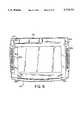
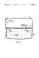
- FIG. 4is a top plan view of the mobile communicator system
- FIG. 5is a bottom plan view of the mobile communicator system
- FIG. 6is a right side elevational view of the mobile communicator system
- FIG. 7is a rear elevational view of the mobile communicator system
- FIG. 8is a perspective view of the mobile communicator system
- FIGS. 9-10are respective bottom plan and rear elevational views of another embodiment of the mobile communicator system.
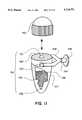
- FIG. 11is a diagram of an antenna mount used with the mobile communicator system
- FIG. 12is a diagram of an antenna mount used with the mobile communicator system
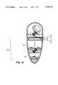
- FIG. 13is a diagram of an antenna used with the mobile communicator system
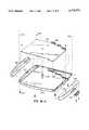
- FIGS. 14-1-14-2are exploded views of the mobile communicator system
- FIG. 15is a top plan view of the upper casing in the mobile communicator system viewed from the inside;
- FIG. 16is an enlarged view of a female connector in the upper casing of the mobile communicator system of FIG. 15;
- FIG. 17is a top plan view of the mobile communicator system viewed from the inside when assembled;
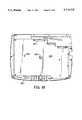
- FIG. 18is a bottom plan view of the mobile communicator system viewed from the inside when assembled;
- FIG. 19Ais an illustration of a first method of determining a responsible party for conditions occurring along a transport route
- FIG. 19Bis an illustration of a second method of determining a responsible party for conditions occurring along a transport route
- FIG. 20illustrates the general layout of a system for determining a responsible party associated with the occurrence of a condition
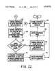
- FIGS. 21-22are flowcharts of the computer implemented process for determining the responsible and/or appropriate party to be notified of the occurrence of a condition(s).
- FIG. 1illustrates the general layout of a system for effectuating the present invention.
- the routecan be one that is well known, or it can be one that is being newly travelled by the vehicle.
- the vehicleis preferably equipped with at least one mobile sensing station, which functions to detect predetermined events or conditions (such as collisions or impacts, potholes or uneven tracks or the like) along the travel route, and transmit data regarding those conditions using the mobile communicator system (not shown) via orbiting satellite 14 to a remote satellite ground station 8 via satellite antenna 10.
- the satellite ground station 8transfers the data received from the mobile communicator system to a dispatch or fleet management center to analyze and evaluate the data.
- Part of the data transmitted from the mobile sensing stationis positional data received or detected from satellite 14 or a separate satellite which is part of a satellite navigation system.
- Examples of presently available systemsare LORAN or the current Global Position System (GPS).
- Navigational data sent to the mobile sensing stationpreferably utilizes a Standard-C data protocol format, which is commonly used in the maritime industry. Experience has indicated that this is the most reliable method of sending navigational data from one mobile station to another.
- a series of radio repeaters located along a predetermined routecan track the location of a specific vehicle and can be used to send location data to the mobile communicator as is done by satellite 14 in FIG. 1.
- other data transfer formatscan be used, depending on the navigational system, the transport route, the vehicle and the communication system for transmitting data from the mobile communicator system.
- FIG. 1illustrates communication between the mobile communicator system in vehicle 18 to satellite 14, the mobile communicator system may also communicate with the fleet management center by means of a cellular telephone system.
- the mobile communicator systemcarries a cellular transceiver capable of automatically accessing cellular ground station 4 as it passes from one cell into another. While such equipment may be more complex and expensive than the satellite uplink embodied in FIG. 1, it facilitates easy communication of instructions from the central controller to the mobile sensing station.
- dual cellular and satellite communication systemsinclude, for example, Westinghouse Series 1000 satellite/cellular mobile telephone or Mitsubishi DiamondTel Series satellite/cellular mobile telephone.
- the fleet dispatch centerincludes a central controller that stores the data sent from the mobile communicator system and arranges it so that it can be used in a display indicating the occurrence of conditions along the route travelled, for example, by vehicle 18.
- the central controlleris expected to handle data from a variety of routes, each travelled by a plurality of vehicles having mobile sensing stations. Since the data are preferably transmitted from the mobile communicator system in ASCII format, the user terminal can access selected data from the central controller using a personal computer (PC), a modem and standard communication software.
- PCpersonal computer
- a display of the desired transport routecan be generated at the PC terminal, and the conditions along the transport route can be updated as information is received from various vehicles having mobile communicator systems travelling along that route.
- boat 16 in FIG. 1also includes a mobile communicator system for communication with satellite 14.
- vehicle 20may communicate with satellite 14 via cellular antenna 6, cellular switching office 4, satellite ground station 8 and satellite antenna 10.
- plain old telephone service (POTS) telephone 12may also communicate with satellite 14 via switching office 8, satellite ground station 8 and satellite antenna 10.
- POTSplain old telephone service
- the mobile communicator systemmay be used to exchange data from among various different vehicles.
- FIG. 2Aillustrates one example of a mobile sensing station 270.
- Antenna 271is used to receive navigational data from a navigational system such as LORAN-C.
- the datais demodulated in receiver 272 so that it can be stored and/or operated on by processor 274.
- the navigational datais correlated with the appropriate occurrences of the conditions detected by sensor module 273.
- the processoralso correlates time and date information to the appropriate data corresponding to the occurrence of conditions detected along the transport route.
- Sensor module 273can be of a single sensor type or of a plurality of different types connected so that indication of a variety of conditions can be transmitted to processor 274.
- the sensor modulescan be located as part of the mobile sensing station package or can be remotely located throughout the vehicle.
- the sensorscan be used to detect a variety of different vehicle conditions, transport route conditions, and cargo conditions.
- the sensor moduleincludes an accelerometer capable of three-axis measurement of acceleration vs. time. In many cases, this is the only sensor data that is needed to determine if transport route conditions are appropriate for the cargo being transported.
- data processor 274After correlating the location data from receiver 272 and the sensor 273, data processor 274 sends the correlated data to transmitter 275 which transmits the correlated data to the satellite 14 via antenna 276. It is a feature of the invention that a transceiver can be substituted for transmitter 275 so that the satellite system can accommodate transmission of data from satellite 14 (in FIG. 1) to the mobile sensing station.
- a transceivercan be substituted for transmitter 275 so that the satellite system can accommodate transmission of data from satellite 14 (in FIG. 1) to the mobile sensing station.
- One such system capable of providing such operationis the satellite communication system operated by American Mobile Satellite Corporation, through its subsidiary, AMSC Subsidiary Corporation, which may be used to facilitate one embodiment of the present invention.
- the systemhas the capability of recording acceleration transients on each measurement axis which exceed a factory preset value of 3Gs as a trigger threshold, and which occur within a 256 millisecond time window.
- the systemrecords the highest acceleration level reached during this time window, and the exact date and time at which it occurred.
- the systemcontinues to operate in this fashion until either it has accumulated a total of 248 peak readings or is interrupted for data download by a remote host terminal such as the central controller.
- This particular version of the mobile sensing stationmay be constituted by a ride recording device such as or similar to the environmental data recorder manufactured by Instrument Sensor Technology in Lansing, Mich.
- the accelerometers in this type of devicehave a measurement range of 0 to ⁇ 10 g, and a resolution of ⁇ 0.4 g.
- the mobile sensing stationis preferably provided with a standard RS-232 serial communication interface with command protocol supplied for customer integration with the host terminal computer for control and data transfer.
- While the mobile sensing station 270may be triggered as described in the previous paragraph, other modes of triggering may also be accomplished.
- the transmission of datacan be triggered by a single occurrence of the conditions, or by some combination of conditions. Triggering may also occur periodically regardless of the number or types of detected conditions.
- a control signal from the central controllermay be transmitted to antenna 276, received by transmitter 275, and used to trigger processor 274.
- the location databe transmitted at the same time as the data regarding the occurrences of the conditions.
- data regarding the occurrence of the conditionsmay be sent as soon as the triggering operation occurs, and a proximity position report may follow within a few minutes.
- the coordination between the two types of datamay be adjusted by processor 274 based upon system parameters and other operating requirements as are necessary to provide a real-time data input of transport route conditions.
- the second-by-second correlation of positional data with data regarding the conditionsis not critical in a railway switching yard since the vehicle spends a substantial amount of time in the same location while being switched.
- a vehicle travelling at high speed along a transport route which may be unfamiliarwill require positional data to be closely correlated with that of the conditions detected along the transport route.
- FIG. 2Bis a block diagram illustrating the elements contained in the mobile communicator system in more detail and in accordance with one preferred embodiment.
- sensor module 24 located in vehicle 22can be of a single sensor type or of a plurality of different types connected so that indication of a variety of conditions can be transmitted to mobile communicator 26.
- sensor module 24preferably includes digital sensor 32 and analog sensor 34.
- Analog sensor 34is equipped with analog to digital (A/D) converter 36 which converts the analog signals into digital signals for transmission to mobile communicator system 26.
- A/Danalog to digital
- Sensor module 24can be used to detect a variety of different vehicle conditions, transport route conditions, and cargo conditions.
- the sensor module 24includes an accelerometer capable of three-axis measurement of acceleration vs. time. In many cases, this is the only sensor data that is needed to determine if transport route conditions are appropriate for the cargo being transported.
- mobile communicator system 26receives the sensor data from sensor module 24 and correlates the data for transmission to the satellite.
- the sensor module 24includes processing capability for correlating and determining when such collected information is to be transmitted to a receiving station.
- Mobile communicator system 26includes input/output serial/parallel port 38 for receiving the sensor data from sensor module 24, and for outputting the correlated sensor data to satellite interface system 28.
- serial/parallel port 38also receives and transmits other data which may be exchanged between the mobile communicator system 26 and, for example, a fleet dispatch center, via the satellite. Data to be transmitted to and received from the satellite may be displayed on display 48 via monitor driver 46. The data may also be printed to a printer connected to the parallel port of serial/parallel port 38, or broadcasted on speaker 68 via speech recognition module 66.
- Mobile communicator system 26also includes video controller 58 for display of data on an external monitor.
- Datais entered in the mobile communicator system 26 via, for example, any one of keyboard 54 using keyboard controller 56, microphone 64 using voice recognition module 62, hard disk 52 via hard disk controller 50, or via an external compact disk via compact disk controller 60.
- Each of the various devicesare connected to central processing unit (CPU) 40 via the system bus.
- CPUcentral processing unit
- CPU 40performs the processing or operations of mobile communicator system 26 as described above.
- CPU 40is conventional, and may be, for example, an IBM compatible 286 or 386 type processor with between 640K -2 MB of random access memory (RAM) and from 20-50 MB of read/write/delete storage such as a standard hard disk 52.
- RAMrandom access memory
- CPUsends the correlated data to satellite interface system 28 which transmits the correlated data to the satellite via antenna 30. It is a feature of the invention that a transceiver can be used for transmitting the data.
- the location databe transmitted at the same time as the data regarding the occurrences of the conditions from the mobile communicator system 26 to the satellite.
- data regarding the occurrence of the conditionsmay be sent as soon as the triggering operation occurs, and a proximity position report may follow within a few minutes.
- the coordination between the two types of datamay be adjusted by CPU 40 based upon system parameters and other operating requirements as are necessary to provide a real-time data input of transport route conditions.
- the second-by-second correlation of positional data with data regarding the conditionsis not critical in a railway switching yard since the vehicle spends a substantial amount of time in the same location while being switched.
- a vehicle travelling at high speed along a transport route which may be unfamiliarwill require positional data to be closely correlated with that of the conditions detected along the transport route.
- Satellite interface system 28receives data from the mobile communicator system 26 via communicator input/output port 72. The received data are then encoded in accordance with predetermined formats which are compatible for the different satellites orbiting the planet earth via satellite encoder/decoder 74. Satellite encoder/decoder 74 also compresses the data to maximize the efficiency of the communication between the satellite interface system 28 and the satellite. Memory 76 may be used to temporarily store the data which is encoded and compressed prior to transmission via satellite transceiver 78, satellite input/output port 80, and antenna 30. The various operations in satellite interface system 28 are coordinated and controlled by controller 82.
- Satellite interface system 28may be comprised of any standard satellite interface system, such as the Trimble Galaxy Inmarsat Land Mobile Transceiver manufactured by Trimble Navigation of Sunnyvale, Calif. Additional interface systems are described in U.S. Pat. Nos. 4,884,208; 4,258,421; The Electronic Motorist, IEEE Spectrum, pp. 37-48 (March 1995); and Remote Sensing, IEEE Spectrum pp. 24-31 (March 1995); all incorporated herein by reference.
- any standard satellite interface systemsuch as the Trimble Galaxy Inmarsat Land Mobile Transceiver manufactured by Trimble Navigation of Sunnyvale, Calif. Additional interface systems are described in U.S. Pat. Nos. 4,884,208; 4,258,421; The Electronic Motorist, IEEE Spectrum, pp. 37-48 (March 1995); and Remote Sensing, IEEE Spectrum pp. 24-31 (March 1995); all incorporated herein by reference.
- the mobile communicator system 26preferably includes sensors, such as transducers 70a-70d.
- Transducers 70a-70dare used to determine the external conditions experienced by the mobile communicator system 26.
- Transducers 70a-70dare strategically placed to record, for example, shock or improper handling of mobile communicator system 26.
- the data generated from transducers 70a-70dare then transmitted to, for example, the fleet management center via satellite interface system 28 and the satellite in a similar manner as the data from the sensors in the vehicle described above.
- mobile communicator system 26includes transducers 70a-70d to determine when occurrences of these adverse conditions occur. The data may then be analyzed, for example, by the fleet management center or the mobile communicator system 26 itself to determine when such external conditions have occurred to assist in determining corrective measures to be taken to ensure the safe or correct handling of the mobile communicator system 26.
- Mobile communicator system 26also includes unique mechanical features which are described in greater detail below. These unique mechanical features provide additional protection for the mobile communicator system 26 in addition to the mobile communicator sensors.
- Antenna 30may be any standard satellite antenna such as the standard C & GPS antenna manufactured by Trimble Navigation of Sunnyvale, Calif. which is generally mounted directly to the vehicle. Alternatively, antenna 30 may be mounted to the vehicle using the antenna mount illustrated in FIG. 11.
- radome 150is shown in exploded view from ballast assembly 118.
- Radome 150houses the satellite antenna 30 of the present invention.
- Mounting plate 152 on ballast assembly 118is provided with female threaded portion 151 for receiving radome 150.
- Female threaded portion 151may comprise, for example, a 5/16-18 threaded hole.
- Mounting plate 152is attached to housing 157 of ballast assembly 118 which is mounted to yoke 158 via pitch gimbal 153.
- Mounting yoke 158is attached to mounting bracket 159 via roll gimbal 154.
- Housing 157contains weight 156 located at the bottom of housing 157.
- weight 156comprises a lead weight, although other types of materials may be used which provide suitable mass.
- dampening fluid 155Within housing 157 lies dampening fluid 155, which may comprise a viscous fluid such as glycol.
- dampening fluid 155The dampening characteristics of dampening fluid 155 are carefully chosen to provide the correct dampening for the antenna mount of FIG. 11.
- dampening fluid 155is selected to provide a fluid which has appropriate freeze temperature characteristics so that dampening fluid 155 will not solidify in normal use. Further, dampening fluid 155 is selected such that the fluid has a relatively constant viscosity characteristics with respect to temperature.
- pitch gimbal 153 and/or roll gimbal 154may be provided with additional shock absorption devices. These devices may take the form of pneumatic or hydraulic dampeners or friction disks inserted in gimbal joint 153, 154 to dampen movement.
- a pneumatic dampenersuch as an Air-PotTM may be used at the rotational joints of gimbals 153, 154.
- hydraulic or pneumatic dampeners 970may be externally mounted.
- Friction disksmay be inserted in gimbal joints 153, 154 with tension maintained on the disks my means of a spring mechanism (e.g., belleville washers or the like) so as to provide a predetermined friction within gimbal joint 153, 154.
- a spring mechanisme.g., belleville washers or the like
- other types of mechanical or hydromechanical dampening units known in the artmay be applied to gimbal joints 153, 154.
- These shock absorption devicesmay be supplied to supplement dampening fluid 155 to aid in the dampening of large accelerations. During large accelerations, the dampening fluid 155 may tend to remain at the bottom portion of antenna mount 118 due to centripetal acceleration.
- Housing 157may be provided with a series of annular rings 160. Annular rings 160 are provided to alter the dampening action of dampening fluid 155 by providing additional surface area to housing 157 to interact with dampening fluid 155.
- the antenna lead cableis not shown in FIG. 11.
- a suitable length of flexible lead cablefor example, may be provided to connect the antenna to shipboard communications equipment. Alternately, a coiled, flexible cable may also be used.
- the antenna unitmay be self-contained, for example, for use as a self-powered emergency beacon.
- contact brushesmay be used at the gimbals in order to provide suitable electrical connections for the antenna. Any suitable technique may be used such that the antenna lead does not interfere with the movement of the antenna mount or act to alter the dampening of the system.
- FIG. 12is a diagram of another antenna mount used with the mobile communicator system having similar construction as the antenna mount in FIG. 11. In FIG. 12, however, two separate fluid ballast compartments 122 and 124 are provided in ballast portion 118'.
- FIG. 12shows an antenna which may be a directional or omnidirectional, mechanically or electronically steered antenna unit. The antenna has one center of gravity while the ballast portion 118' including the housing, dampening fluids, etc. has another center of gravity.
- Both FIGS. 11 and 12include a ballast weight comprised of a suitably dense material such as lead.
- Dampening fluids disposed in the fluid chamberspreferably comprise a fluid in the viscosity range of 6 to 1000 centipoise, having a specific gravity range of 0.6 to 2.23 grams per centimeter squared. Both the specific gravity and viscosity of dampening fluids should be relatively constant over a broad temperature range (e.g., -40° C. to 100° C.) or at least remain within the above limits over this temperature range. Additional details of the above antenna mount in FIGS. 11 and 12 are disclosed in copending application Ser. No. 08/058,079 filed May 10, 1993, incorporated herein by reference. Alternatively, the antenna mounts in FIGS. 11 and 12 may also include a ballast tank containing fluid above the fulcrum point of the antenna mount, e.g., above gimbal joints 153, 154 in FIG. 11.
- a range of 20° to 60°is particularly suitable for use in the CONUS, as this range of elevation corresponds to the angles of inclination between a geostable satellite and locations throughout the CONUS.
- Other ranges of anglescould, of course, be used if the antenna is to be used in another country or countries.
- a narrower rangecould be used in applications where the mobile vehicle is anticipated as having a limited range of travel.
- a fixed elevation anglecould be chosen for stationary antennas or antennas used in local mobile applications.
- an adjustment rangecould be provided from 0° (horizon) to 90° (zenith) to provide global coverage.
- the preferred range of 20° to 60°is shown here for use in the CONUS and is in no way intended to limit the scope of the invention.
- the antennais designed to mount to a detachable base 201 located on the vehicle skin (e.g., trunk, fender, roof or the like) 202. Its scanned radiation angle is set manually by the vehicle operator with the relatively simple adjustment of a knurled sleeve 222 at the base 217 of the antenna.
- vehicle skine.g., trunk, fender, roof or the like
- Helix elements 205 and 206are formed by being wound around a constant diameter tube to form a uniform helix.
- the angle of pitch of helix 204is determined by the number of helix turns for a given axial length.
- Pitch in unit lengthis defined as the axial length required for the helix to make one complete turn about its axis.
- the spacing (helix diameter) and angle of pitch of helix 204determines the polarization and radiation characteristics of the antenna.
- a bifilar helix with left-handed helices (ascending counter-clockwise as viewed from the bottom)radiates a right-hand circularly-polarized (RHCP) wave which is relatively omni-directional in azimuth. If the pitch angle and or the diameter of helix 204 is increased from an initial reference point, the radiation in elevation is scanned towards the horizon.
- the element pitch angle and helix diameterare adjusted by varying the number of helix turns for a fixed axial length.
- helix elements 205 and 206are made from 300 ohm twin lead line commonly used in FM receivers and some television leads. One of the conducting leads is removed from the polypropylene sheathing of each of helix elements 205 and 206, while the remaining lead serves as the radiating element. Thus, helix elements 205 and 206 each contain only one wire.
- Formed helix elements 205 and 206are placed over a 31 inch long 3/8 inch diameter hollow supporting tube 212 which may be made of any fairly robust insulating material such as phenolic resin.
- Supporting tube 212is centrally located within a 32 inch long outer sheath 213 which is one inch in diameter.
- Outer sheath 213also may be formed of any robust insulating material such as polycarbonate and serves to provide environmental sealing of the antenna assembly.
- Coaxial cable 211is fed through the center of supporting tube 212 and is terminated at the distal end 209 at balun 214.
- Coaxial cable 211may be formed from a UT141 semi rigid coaxial line.
- Balun 214comprises a hollow 3/16 inch diameter brass tube with two feed screws 223 and 224 located 180° apart. The wire portions of Helix elements 205 and 206 are secured to the termination of balun 214, one on each side, by feed screws 223 and 224. Proximal end 210 of coaxial line 211 is terminated by connector 216 which may be press fitted into base 217 of the antenna. Balun 214 serves to maintain a relative phase difference of 180° between the radiating elements for the required frequency bands.
- balun 214comprises a hollow 3/16 inch diameter slotted brass tube with two slots in the tube located 180° apart.
- the slotsare 0.124 inches wide by 1.85 inches long.
- the wire portions of Helix elements 205 and 206are soldered to the termination of balun 214, one on each side, separated by the slots.
- Support tube 212is captured at distal end 209 by end cap 218 set into distal end 209 of outer sheath 213 so as to prevent support tube 212 from rotating.
- End cap 218is secured to distal end 209 of outer sheath 213 by glue, screws, threading, press fit, or the like.
- Proximal end 210 of support tube 212is movably attached to inner rotatable sleeve 219 by threaded member 226.
- Threaded member 226may be, for example, a 1/4-20 threaded stainless steel sleeve.
- Spring 225is installed at the point of rotation between support tube 212 and inner rotatable sleeve 219 to prevent undesired relative movement between inner rotatable sleeve 219 and support tube 212.
- Spring 225may be made of, for example, stainless steel.
- Inner rotatable sleeve 219is held in place by two set screws 221 within knurled adjustment outer sleeve 222.
- Helix 204preferably made of polypropylene, has the desirous property of maintaining a uniform pitch along its axial length, even when one end is rotated with respect to the other.
- helix elements 205 and 206make approximately six and one-half turns within the axial length of antenna 200. This allows for coverage within 20° above the horizon. In the other extreme, helix elements 205 and 206 make just under ten complete turns, allowing for coverage up to 60° above the horizon.
- a mechanical limiter (not shown) and elevation angle indicator (not shown)are used to prevent the user from forcing the helix elements beyond their six and one-half and ten turn limits and to simplify the process for optimizing the antenna for elevation coverage.
- the operator's choice of elevation anglecan be determined from the latitude where the vehicle is located, or can be positioned with the aid of a standard electronic antenna peaking device. Additional details of the above antenna in FIG. 13 are disclosed in copending application Ser. No. 08/187,996 filed Jan. 28, 1994, incorporated herein by reference.
- FIG. 3is a flow chart illustrating the process implemented by the mobile communicator system.
- the mobile communicator system 26receives sensor data from, for example, sensors located in the cargo area of vehicle in step S2.
- Mobile communicator system 26compares the previously sampled sensor data to the current sensor data in step S4, and determines whether or not the change in the data exceeds the predetermined threshold indicating that a significant change in the data has occurred in step 56.
- Mobile communicator system 26also receives sensor data from the communicator itself in step S8, for example, from transducers 70a-70d illustrated in FIG. 2B. Mobile communicator system 26 then compares the previously sampled sensor data to the current sensor data in step S10, and determines whether the change in sensor data has exceeded a predetermined threshold magnitude in step 512.
- mobile communicator system 26If the change in sensor data in both steps S6 and S12 have not exceeded their respective threshold magnitudes, mobile communicator system 26 then waits for additional sensor data to be received in step S14. If either of steps S6 or S12 determine that the change in sensor data exceeds the predetermined threshold, mobile communicator system 26 generates a location device warning to the operator in step S16 indicating whether the cargo or mobile communicator system have experienced adverse conditions. In addition, this sensor data is also broadcast to the satellite including the location information of the vehicle in step S18, which data is then received at a dispatch center in step S20.
- the sensor history and location dataare then stored in a central controller in the dispatch center in step S22, and the central controller determines the trouble locations and whether or not the mobile communicator device has experienced adverse conditions in step S24.
- the trouble locationsare then dispatched to the fleet in step S26 as well as suggested corrective measures for the vehicle operator to perform with respect to preventing any future adverse conditions to the cargo or the mobile communicator system in step S28.
- FIGS. 4-8are different views of the mobile communicator system.
- mobile communicator system 26includes left and right end bumpers 82a, 82b, each with left and right recessed handles 84a, 84b disposed therein on the upper surface of end bumpers 82a, 82b.
- finger grips 92a, 92bare respectively positioned on the opposite side of end bumpers 82a, 82b which further provide traction for gripping mobile communicator system 26.
- end bumpers 82a, 82b with recessed handles 84a, 84b and finger grips 92a, 92bprovide an effective way of protecting mobile communicator device 26 while being handled or gripped by the vehicle operator.
- Mobile communicator device 26further includes keyboard 86 with inclined palm rest 88 and display 90.
- Keyboard 86is designed in such a manner to insure that no fluids which might be encountered by mobile communicator system 26 be permitted to pass therethrough. Accordingly, keyboard 86 is comprised of a standard rubber/carbon keyboard which, however, is sealed to the opening around the outer edges of mobile communicator system 26 corresponding to keyboard 86. In this manner, fluids which are spilled onto keyboard 86 will not enter the electrical components of the mobile communicator system 26 Resistive or mechanical switches may be disposed below keyboard 86 for selecting specific characters.
- Display 90also advantageously comprises a shock resistant material, such as tempered glass having a thickness of approximately 0.125 inches.
- Display 90is sealed to the housing of mobile communicator system 26 using a seal material such as silicon foam applied to the outer edge of display 90 and the housing using an adhesive.
- the exterior housing of mobile communicator system 26is preferably constructed of a shock resistant material, such as a polycarbonite, or G. E. Cycoloy type material.
- End bumpers 82a, 82bmay comprise a elastomeric or silicon rubber. Accordingly, this extremely durable exterior of mobile communicator system 26 provides additional protection which was discovered to be necessary for such a device when used in a vehicle as described and contemplated.
- Mobile communicator device 26further includes the feature of steering wheel steps or rests, 96a, 96b which permit the vehicle operator to temporarily mount mobile communicator system 26 on the steering wheel for convenience of use. Further, mobile communicator device 26 includes recessed area 100 and cable outlet access 102 in right end bumper 82b for further organizing the various cables which may be connected to mobile communicator device 26, and for organizing the cables which are required to be plugged therein, for example, end cable plugs 108 and 110.
- Mobile communicator system 26also includes the advantageous features of sensors embedded therein to automatically determine mishandling of the mobile communicator system, together with a durable and shock resistant exterior.
- mobile communicator system 26includes the conveniences of being able to temporarily mount the device on the steering wheel of a vehicle, as well as organizing the cables in a manner which minimizes the intrusiveness thereof.
- mobile communicator system 26includes means which facilitates the easy handling of the device by providing hand grips on both sides of the device in the end bumpers.
- Mobile communicator system 26also includes PCMCIA port 106 which is covered by a rubber protective cap in which also includes recessed access portion 94 for opening the rubber cover to gain access to the PCMCIA port.
- FIGS. 9-10are respective bottom plan and rear elevational views of another embodiment of the mobile communicator system.
- the remaining views of mobile communicator deviceare essentially similar as described in connection with the first embodiment.
- mobile communicator deviceincludes modified recessed area 100' which accommodates multiple input/output ports 112, 114, and 116.
- recessed area 100'is configured in a step like function or manner so that the corresponding cable ends for each of the cables do not interfere with each other and which permit the cables to be uniformly exited through exit hole 104 of right end bumper 82b.
- FIGS. 14-1-14-2are exploded views of the mobile communicator system showing the inner components.
- FIG. 14-1illustrates the construction of the upper portion of the mobile communicator system
- FIG. 14-2illustrates the construction of the lower portion of the mobile communicator system.
- the upper and lower portionsare assembled together as illustrated by dashed lines 246a and 246b and connection screws 248.
- Connection screws 248are attached or mounted to female connectors mounted in the upper portion described in detail below in connection with FIG. 16.
- the upper portion in FIG. 14-1comprises upper casing 230 with upper handle receiving portions 231a and 231b.
- Upper handle receiving portions 231a and 231bare used for mounting end bumpers 82a, 82b illustrated in FIG. 14-2.
- End bumpers 231a and 231badvantageously serve to protect the mobile communicator system from adverse conditions, such as mishandling, falls, etc.
- Upper casing 230includes elastomer sections 232a and 232b and tempered glass 90 for protecting monitor 236 used to display data transmitted and received between the mobile communicator system and a central control system, sensors, etc.
- Elastomer sections 232a and 232bare used to absorb shock experienced by the mobile communicator system, thereby protecting tempered glass 90 from being broken, chipped or shattered. Elastomer sections 232a and 232b are also used as a seal for the monitor portion of the mobile communicator system preventing or inhibiting the entrance of fluid therein. Similarly, tempered glass 90 protects monitor 236 from the external conditions experienced or encountered by the mobile communicator system.
- An additional elastomer or foamed material 234is advantageously disposed or arranged between tempered glass 90 and monitor 236.
- Foamed material 234may be adhesively secured to either of the monitor 236 or tempered glass 90.
- Tempered glass 90may be either chemically or heat treated tempered glass.
- An additional foamed material similar in construction to foamed material 234may also advantageously be disposed between upper casing 230 and tempered glass 90.
- Monitor 236includes screw holes 237 advantageously shaped in the size of a "half moon.” As will be described in detail below, screw holes 237 facilitate the easy removal of monitor 236 while maintaining connection of other components inside the mobile communicator system.
- the upper portion of the mobile communicator systemsalso includes keyboard related components which are mounted to upper casing 230.
- keyboard 86is comprised of a standard rubber/carbon keyboard which, however, is sealed to the opening around the outer edges of the mobile communicator system. In this manner, fluids which are spilled onto keyboard 86 will not enter the electrical components of the mobile communicator system.
- keyboard 86includes mounting holes 235 around its periphery in a "half moon" shape as well as circular holes placed between the various elevated keys.
- Printed circuit board 238includes resistive switches positioned below the keys of keyboard 86 for selecting specific characters.
- Screws 240are used to mount printed circuit board 238 and keyboard 86 to upper casing 230 in a secure and water resistant or water proof manner as will be described in detail below. Screws 240 enter holes in printed circuit board 238 and mounting holes 235 around the periphery and within keyboard 86.
- Mounting bracket 242is then positioned above monitor 236 and printed circuit board 238 for securely mounting the keyboard and monitor components to upper casing 230 via screws 244.
- Screws 244advantageously are not inserted in any circular hole in monitor 236, but rather are inserted in "half moon” shaped hole 237 of monitor 236, permitting easy removal and insertion of monitor 236 from upper casing 230.
- the pressure exerted from screws 244 on mounting bracket 242 and monitor 236thereby holds or retains monitor 236 to upper casing 230.
- the bottom portion of the mobile communicator system in FIG. 14-2includes lower casing 250 with lower handle receiving portions 231c and 231d which cooperate with upper handle receiving portions 231a and 231b for mounting end bumpers 82a and 82b to the upper and lower casings 230 and 250.
- End bumper 82bis advantageously configured to include a recessed portion which receives cable securing member 252 mounted thereto.
- Cable securing member 252is used to affix or secure cables which are connected between input/output ports 257 of the mobile communicator system to external devices or destinations. Input/output ports 257 are connected to printed circuit board 256 which advantageously comprises the overall microprocessor circuitry for performing the processes of the mobile communicator system.
- Printed circuit board 256is advantageously mounted to lower casing 250 via screws 258, and includes a center hole for receiving therethrough support 254.
- Support 254is mounted to lower casing 250 and is used to maintain clearance between upper and lower casings 230 and 250 as well as prevent buckling of the upper and lower casings 230 and 250 together. Thus, support 254 is an important structural feature of the lower casing 250.
- support 254includes at its upper surface a rubber or shock absorbing element that reduces or distributes the shock experienced by the mobile communicator and on its inner components.
- this additional shock absorbing elementis also a feature of the structure of the mobile communicator bracing system.
- FIGS. 14-1 and 14-2therefore illustrates the modular construction of the mobile communicator system which permits the various components relating to the keyboard, monitor and microprocessor related elements to be securely mounted to the upper and lower casings 230 and 250. Accordingly, the components within the mobile communicator system are protected from external shock and external conditions, including the feature of being water resistant.
- FIG. 15is a top plan view of the upper casing in the mobile communicator system viewed from the inside. No internal components of the mobile communicator system have been mounted to upper casing 230.
- upper casing 230includes protruding or elevated rod or stick-like portions 260 which extend around the monitor opening of upper casing 230.
- Elastomer sections 232a and 232b(shown in FIG. 14-1) are placed on elevated portions 260 and used as a seal for the monitor portion of the mobile communicator system, preventing or inhibiting the entrance of fluid therein.
- Keyboard template 263includes female mounting connectors 262 and 264 which extend above the surface and which enter or penetrate through keyboard holes 235 in keyboard 86 (keyboard holes 235 and keyboard 86 are illustrated in FIG. 14-1).
- FIG. 17is a top plan view of the mobile communicator system viewed from the inside when assembled. As shown in FIG. 17, monitor 236 is secured by the pressure of mounting bracket being fixed to the upper casing via screws 244. Printed circuit board 238 (used in connection with the keyboard) is also mounted to the upper casing via screws 240.
- FIG. 18is a bottom plan view of the mobile communicator system viewed from the inside when assembled.
- printed circuit board 256is secured via screws 258 to the lower casing 250.
- Input/output ports 257are positioned to cooperate with external holes (not shown) in the lower casing 250 for connection to external devices or destinations.
- Support 254protrudes through a hole in printed circuit board 256, and prevents the lower and upper casings from buckling inward.
- the present inventionalso provides the capability to identify and notify an appropriate party.
- An appropriate partycan be, for example, a party that may assume responsibility for any damage to a vehicle or cargo contained therein on a predesignated geographic location, or a party interested in monitoring their own vehicles that are in transit on transport routes of others.
- the geographic locationmay be determined based on a particular transport route, based on a specific geographic area, and the like.
- a central controllerthat is unbiased with respect to the various parties participating herein is able to determine the party that is responsible for conditions occurring thereon.
- the central controlleridentifies, not only knowledge of where the condition has occurred, but also identifies a responsible or appropriate party to be notified of the condition.
- an appropriate party to receive notification of the occurrence of the conditionmay be as the owner of the geographic location, owner of the facilities in a specific geographic location (e.g., owner of railroad track, private road, parking lot, etc.), and the like.
- This routing and dispatching systemdetermines on a real-time basis the appropriate party to be notified of a condition, for example, a carrier that was handling the railroad car or truck at the time of an alarm message, and to dispatch the message to that party/carrier.
- a standard geographic server or global positioning systemprovides longitude and latitude coordinates of the vehicle and the conditions to assist in the determination of the appropriate party.
- the global positioning systemdetermines the vehicle's location within seconds after an event or condition triggers a message that is transmitted to the central controller.
- the global positioning systemprovides functions that interface or cooperate with other geographic information to identify the appropriate party to be contacted, such as notifying a railroad carrier when the railroad carriers' tracks are in close geographic proximity to the reported location of the event or condition.
- the routing and dispatching systemincludes decision rules that choose, if geographic analysis suggests, for example, several possible roads, those roads that are in the route over those that are not.
- Another example rulerelates to reporting delays. Since reporting delays may affect the timeliness of certain data, for example, the TRAIN II data, an expedient rule we have added, for example, states if the geographic server does not return the road suggested by TRAIN II data but does return a road that appears later in the route, choose the latter road that appears later in the route.
- Examples of data that may be collected from the mobile sensing station and/or a secondary data source such as the TRAIN IIare:
- Type of cargo carried by vehicleperishable, breakable, edible, boxed, vacuum packed, etc.
- examples of information requested from the routing and dispatching systemmay include:
- a description of the location of the given geographic point where the condition occurs relative to the nearest rail freight station or stationsis provided.
- the descriptionpreferably includes distance, direction of location (e.g., city, state, railroad), and the like. If two or more stations are nearly equidistant from the point, all will be returned.
- FIG. 19Ais an illustration of a first method of determining a responsible party for, or appropriate party to be notified of, conditions occurring along a transport route.
- separate geographic areasare designated at 277, 278, 279 and 280 representing separate areas for which different parties are responsible for conditions.
- the separate geographic areasare generally predesignated before the central controller determines the responsible party. However, the separate geographic areas may be altered as well, either statically or dynamically while the vehicles are in transport.
- Vehicles 281, 282, 283 and 284are located in separate geographic areas 277, 278, 279 and 280, respectively. Separate geographic areas 277, 278, 279 and 280 are bounded by vertical dotted lines 285, 286 and 287.
- the central controllerstores data bounding the separate geographic areas 277, 278, 279 and 280.
- the central controllermaps this condition to a specific geographic area to determine the responsible party or appropriate party to be notified of the condition.
- the central controllerthen notifies the party associated with the geographic area where the condition occurs.
- the central controllermay also notify the party associated with the vehicle as well based on vehicle identification, if the party associated with the vehicle is different than the party associated with the geographic area. This is discussed in detail below.
- FIG. 19Bis an illustration of a second method of determining a responsible party for, or appropriate party to be notified of, conditions occurring along a transport route.
- separate transport routesare designated at 292, 293, 294 and 295 representing separate routes for which different parties are responsible for conditions.
- the separate routesare generally predesignated before the central controller determines the responsible party. However, the separate routes may be altered as well, either statically or dynamically while the vehicles are in transport. Vehicles 288, 289, 290 and 291 are located in separate routes 292, 293, 294 and 295, respectively. In this arrangement, separate routes 292, 293, 294 and 295 are not generally bounded. Other configurations for designating separate routes are, of course, also possible.
- an engine companycan be the responsible party for the occurrence of an engine condition (e.g., low oil, overheating, etc.)
- a cargo companycan be the responsible party for a cargo related condition (e.g., cargo damage)
- a truck companycan be the responsible party for a truck condition (e.g., speeding).
- the central controllerstores data identifying the separate transport routes 292, 293, 294 and 295. When the central controller receives a signal from the satellite indicating the occurrence of a condition, the central controller maps this condition to a specific transport route to determine the responsible/appropriate party.
- the central controllerthen notifies the appropriate party associated with the transport route, such as the owner of the railroad track or governmental authority.
- the central controllermay also notify the party associated with the vehicle as well based on vehicle identification, if the party associated with the vehicle is different than the party associated with the transport route.
- FIG. 20illustrates the general layout of a system for determining a responsible party for, or appropriate party to be notified of, the occurrence of a condition.
- a vehicle 301usually transporting cargo, moves along a transport route.
- the routecan be one that is well known, or it can be one that is being newly travelled by the vehicle.
- the vehiclecarries at least one mobile sensing station 302, which functions to detect events or conditions (such as collisions or impacts, potholes or uneven tracks or the like) along the travel route, and transmit data regarding those conditions via orbiting satellite 304 to a remote ground station 305.
- the ground stationtransfers the data from the mobile sensing station to the central controller 305 through data link 306.
- a user terminal 309can access data in the central controller via communications link 308.
- Central controller 307has access to data base 303 that stores suitable data for determining a responsible or appropriate party associated with the occurrence of a condition.
- data base 303may include data identifying the responsible party by transport route, by geographic location, by type of condition, by any combination of the above, as well as for other criteria.
- the central controllerreceives the various condition data and assigns a responsible party for, or appropriate party to be notified of, the condition responsive thereto. If the various condition data represent conflicting responsible or appropriate parties, the central controller determines a ranking for the parties. One method of ranking the responsible party may be the time or order at which the condition occurred. For example, if a cargo related condition occurs first and then an engine related condition, the responsible party may be determined, for example, by assigning the party associated with a cargo condition as the responsible party.
- conditions that are related to each other, or the combination of conditions togethermay indicate a responsible party.
- a speeding conditionmight be detected while at the same time a braking condition is detected.
- the speeding conditionmight be the result of the failure of the brakes, and therefore, the responsible party assigned by the central controller would be the braking company and not the trucking company.
- data base 303stores information relating to the conditions, and central controller 307 determines the responsible party as described above.
- FIGS. 21-22are flowcharts of the computer implemented process for determining the responsible and/or appropriate party to be notified of the occurrence of a condition(s).
- a conditionis detected by the mobile sensing station at step S30.
- the mobile sensing station or mobile communicator itselfdetermines whether the condition has exceeded a threshold, thereby indicating that the central controller/clearinghouse it to be notified of the occurrence of the condition in step S32. If the condition exceeds the threshold then control is directed to step S34 for additional processing, and if not, control is returned to the monitoring of the occurrence of conditions.
- step S34the mobile communicator transmits data describing the condition to a satellite for real-time notification to the central controller.
- the satellitereceives the data from the mobile communicator in step S36, and transmits same to the central controller/clearinghouse in step S38.
- the central controllerthen analyzes the data in step S40, and determines whether the appropriate party to be notified can be discerned in step S42 with a predetermined level of accuracy (as discussed above).
- the central controllerWhen the central controller can determine the appropriate party to be notified in step S42, the central controller then generates, in step S44, a message to be transmitted to the appropriate party (described above) informing same of the condition.
- the central controllerretrieves additional auxiliary data from external data sources to further assist in the determination of the appropriate party to be notified in step S46 (discussed above).
- the central controlleruses the auxiliary data alone or in combination with the previously received data from the mobile communicator to determine the appropriate party in step S48, and optionally determines whether the data received from the mobile communicator and the auxiliary data are consistent in step S50. If the two types of data are consistent as determined in step S50, the central controller next determines the appropriate party using at least one of the mobile communicator and the auxiliary data in step S52, and notifies the appropriate party of the condition in step S54.
- the central controllerWhen the auxiliary data and the mobile communicator data are not sufficiently consistent as determined by the central controller in step S50, the central controller utilizes rules to resolve the inconsistency and identify the appropriate party (as discussed above) in step S56. The central controller then notifies the appropriate party in step S58. Finally, the central controller also optionally informs the vehicle operator of the conditions detected regarding the vehicle or cargo stored therein received from the vehicle or other vehicles on the transport route in step S60. For example, the vehicle operator can be instructed where to stop to inspect the cargo or vehicle responsive to the detection of the condition. The vehicle operator may be instructed to stop at the appropriate party that has been notified of the condition, including a party responsible for the occurrence of the condition to verify or determine whether any actual damage resulted to the vehicle or cargo stored therein.
Landscapes
- Physics & Mathematics (AREA)
- General Physics & Mathematics (AREA)
- Management, Administration, Business Operations System, And Electronic Commerce (AREA)
- Traffic Control Systems (AREA)
- Navigation (AREA)
Abstract
Description
Claims (46)
Priority Applications (1)
| Application Number | Priority Date | Filing Date | Title |
|---|---|---|---|
| US08/566,410US5719771A (en) | 1993-02-24 | 1995-12-01 | System for mapping occurrences of conditions in a transport route |
Applications Claiming Priority (2)
| Application Number | Priority Date | Filing Date | Title |
|---|---|---|---|
| US08/022,037US5475597A (en) | 1993-02-24 | 1993-02-24 | System for mapping occurrences of predetermined conditions in a transport route |
| US08/566,410US5719771A (en) | 1993-02-24 | 1995-12-01 | System for mapping occurrences of conditions in a transport route |
Related Parent Applications (1)
| Application Number | Title | Priority Date | Filing Date |
|---|---|---|---|
| US08/022,037Continuation-In-PartUS5475597A (en) | 1993-02-24 | 1993-02-24 | System for mapping occurrences of predetermined conditions in a transport route |
Publications (1)
| Publication Number | Publication Date |
|---|---|
| US5719771Atrue US5719771A (en) | 1998-02-17 |
Family
ID=46251699
Family Applications (1)
| Application Number | Title | Priority Date | Filing Date |
|---|---|---|---|
| US08/566,410Expired - LifetimeUS5719771A (en) | 1993-02-24 | 1995-12-01 | System for mapping occurrences of conditions in a transport route |
Country Status (1)
| Country | Link |
|---|---|
| US (1) | US5719771A (en) |
Cited By (230)
| Publication number | Priority date | Publication date | Assignee | Title |
|---|---|---|---|---|
| WO1999031575A1 (en)* | 1997-12-16 | 1999-06-24 | Khawam Maurice A | Wireless vehicle location and emergency notification system |
| US5922041A (en)* | 1996-09-18 | 1999-07-13 | Magellan Dis, Inc. | Navigation simulator and recorder |
| US5926117A (en)* | 1997-06-10 | 1999-07-20 | Hitachi, Ltd. | Vehicle control system, vehicle mounting apparatus, base station apparatus and vehicle control method |
| US5987979A (en)* | 1996-04-01 | 1999-11-23 | Cairo Systems, Inc. | Method and apparatus for detecting railtrack failures by comparing data from a plurality of railcars |
| WO2000019171A1 (en)* | 1998-09-30 | 2000-04-06 | Global Research Systems, Inc. | System and method for an advance notification system for monitoring and reporting proximity of a vehicle |
| US6073075A (en)* | 1995-11-01 | 2000-06-06 | Hitachi, Ltd. | Method and system for providing information for a mobile terminal |
| US6111541A (en)* | 1997-05-09 | 2000-08-29 | Sony Corporation | Positioning system using packet radio to provide differential global positioning satellite corrections and information relative to a position |
| US6112174A (en)* | 1996-11-13 | 2000-08-29 | Hitachi, Ltd. | Recognition dictionary system structure and changeover method of speech recognition system for car navigation |
| US6115655A (en)* | 1998-01-27 | 2000-09-05 | Keith; W. Curtis | Method for monitoring and reporting vehicular mileage |
| US6188315B1 (en)* | 1998-05-07 | 2001-02-13 | Jaguar Cars, Limited | Situational feature suppression system |
| US6208859B1 (en)* | 1997-02-26 | 2001-03-27 | Motient Services Inc. | Service preemption for mobile terminals in a mobile satellite communications system |
| US6232888B1 (en)* | 1999-12-07 | 2001-05-15 | Cue Corporation | Traffic paging system |
| US6304816B1 (en) | 1999-01-28 | 2001-10-16 | International Business Machines Corporation | Method and apparatus for automatic traffic conditions data collection using a distributed automotive computing system |
| US20010037360A1 (en)* | 2000-05-12 | 2001-11-01 | Koninklijke Philips Electronics N.V. | Data service at a transit terminal |
| US20010039489A1 (en)* | 1996-09-16 | 2001-11-08 | Ford Terry Edward | Spatial asset management system and method |
| US6317060B1 (en) | 1999-03-01 | 2001-11-13 | Global Research Systems, Inc. | Base station system and method for monitoring travel of mobile vehicles and communicating notification messages |
| US20010041535A1 (en)* | 1997-05-09 | 2001-11-15 | Karmel Clayton R. | Positioning system using packet radio to determine position and to obtain information relative to a position |
| US20020009454A1 (en)* | 1997-02-10 | 2002-01-24 | Amgen Inc. | Composition and method for treating inflammatory diseases |
| US6363323B1 (en) | 1993-05-18 | 2002-03-26 | Global Research Systems, Inc. | Apparatus and method for monitoring travel of a mobile vehicle |
| US6374178B2 (en)* | 1998-05-15 | 2002-04-16 | Suntory Limited | Transportation arrangement system and transportation arrangement apparatus |
| EP1202234A1 (en)* | 2000-10-24 | 2002-05-02 | @Road, Inc. | Targeted impending arrival notification of a wirelessly connected location device |
| US6396454B1 (en) | 2000-06-23 | 2002-05-28 | Cue Corporation | Radio unit for computer systems |
| US6404352B1 (en)* | 1999-05-24 | 2002-06-11 | Matsushita Electric Industrial Co., Ltd. | Mobile terminal and emergency reporting system |
| US6411891B1 (en) | 1997-03-10 | 2002-06-25 | Global Research Systems, Inc. | Advance notification system and method utilizing user-definable notification time periods |
| US6411220B1 (en) | 1999-12-07 | 2002-06-25 | Cue Corporation | Traffic paging system |
| US6415207B1 (en) | 1999-03-01 | 2002-07-02 | Global Research Systems, Inc. | System and method for automatically providing vehicle status information |
| US6421354B1 (en) | 1999-08-18 | 2002-07-16 | Phoenix Datacomm, Inc. | System and method for retrieval of data from remote sensors using multiple communication channels |
| US6426709B1 (en)* | 1996-12-09 | 2002-07-30 | Mannesmann Ag | Method for transmitting local data and measurement data from a terminal, including a telematic terminal, to a central traffic control unit |
| US20020107912A1 (en)* | 2001-02-08 | 2002-08-08 | Lear Corporation | Motor vehicle drive recorder system which records motor vehicle data proximate an event declared by a motor veicle occupant |
| US6484089B1 (en) | 1999-10-15 | 2002-11-19 | Magellan Dis, Inc. | Navigation system with road condition sampling |
| US6484079B2 (en) | 2000-04-28 | 2002-11-19 | Rmc Industries Corporation | Methods and systems for remotely monitoring sensor data in delivery vehicles |
| US6492912B1 (en) | 1993-05-18 | 2002-12-10 | Arrivalstar, Inc. | System and method for efficiently notifying users of impending arrivals of vehicles |
| US6505104B2 (en) | 2000-07-07 | 2003-01-07 | Jonathan Collins | Routing method and system for railway brake control devices |
| US6505106B1 (en)* | 1999-05-06 | 2003-01-07 | International Business Machines Corporation | Analysis and profiling of vehicle fleet data |
| US6518889B2 (en)* | 1998-07-06 | 2003-02-11 | Dan Schlager | Voice-activated personal alarm |
| US20030036935A1 (en)* | 2001-08-15 | 2003-02-20 | Nel Andre M. E. | Allocating freight haulage jobs |
| US20030046451A1 (en)* | 1997-03-07 | 2003-03-06 | Mobile Information System, Inc. | System and method for mobile data processing and transmission |
| US6542077B2 (en) | 1993-06-08 | 2003-04-01 | Raymond Anthony Joao | Monitoring apparatus for a vehicle and/or a premises |
| US20030067541A1 (en)* | 1996-03-27 | 2003-04-10 | Joao Raymond Anthony | Monitoring apparatus and method |
| US6549130B1 (en) | 1993-06-08 | 2003-04-15 | Raymond Anthony Joao | Control apparatus and method for vehicles and/or for premises |
| US6549834B2 (en)* | 1999-03-01 | 2003-04-15 | Independent Witness Incorporated | Motion detection and recording method and apparatus |
| US20030078057A1 (en)* | 2001-09-28 | 2003-04-24 | Pioneer Corporation | Communication navigation system, information server unit and communication terminal unit for the same, and method and program for communication navigation |
| US6556905B1 (en) | 2000-08-31 | 2003-04-29 | Lisa M. Mittelsteadt | Vehicle supervision and monitoring |
| US6567000B2 (en)* | 1995-11-28 | 2003-05-20 | Timothy P. Slifkin | Methods and means for monitoring events in vehicles |
| US20030098802A1 (en)* | 1999-03-01 | 2003-05-29 | Jones Martin Kelly | Base station apparatus and method for monitoring travel of a mobile vehicle |
| US6580367B2 (en)* | 2001-01-02 | 2003-06-17 | John Edward Roach | Vehicle information dispatch system |
| US6587046B2 (en) | 1996-03-27 | 2003-07-01 | Raymond Anthony Joao | Monitoring apparatus and method |
| US6611755B1 (en)* | 1999-12-19 | 2003-08-26 | Trimble Navigation Ltd. | Vehicle tracking, communication and fleet management system |
| US6618668B1 (en) | 2000-04-26 | 2003-09-09 | Arrivalstar, Inc. | System and method for obtaining vehicle schedule information in an advance notification system |
| US20030193413A1 (en)* | 1993-05-18 | 2003-10-16 | Jones M. Kelly | Business methods for notification systems |
| US6658392B2 (en)* | 1997-09-05 | 2003-12-02 | Denso Corporation | Automatic toll collection system for automotive vehicle |
| US20030233188A1 (en)* | 1993-05-18 | 2003-12-18 | Jones M. Kelly | Notification systems and methods with user-definable notifications based upon occurance of events |
| US20030233286A1 (en)* | 2002-05-10 | 2003-12-18 | Hahn-Carlson Dean W. | Automated transaction processing system and approach |
| US20040001022A1 (en)* | 2002-01-22 | 2004-01-01 | Inforetech Wireless Technology, Inc. | Endurable sports PDA with communications capabilities and accessories therefor |
| US6675019B1 (en)* | 1998-07-03 | 2004-01-06 | James D. Thomson | Logistical and accident response radio identifier |
| US6678612B1 (en) | 1997-12-16 | 2004-01-13 | Maurice A. Khawam | Wireless vehicle location and emergency notification system |
| US6700507B2 (en) | 1993-05-18 | 2004-03-02 | Arrivalstar, Inc. | Advance notification system and method utilizing vehicle signaling |
| US6711496B2 (en)* | 2001-11-01 | 2004-03-23 | Jack A. Denton | System and method of monitoring cargo container mobility and efficiency |
| US6718263B1 (en)* | 2000-12-27 | 2004-04-06 | Advanced Tracking Technologies, Inc. | Travel tracker network system |
| US20040073382A1 (en)* | 2002-10-11 | 2004-04-15 | Troxler Electronic Laboratories, Inc. | Measurement device incorporating a locating device and a portable handheld computer device and associated apparatus, system and method |
| US6742037B1 (en)* | 1998-12-01 | 2004-05-25 | Nortel Networks Limited | Method and apparatus for dynamic information transfer from a mobile target to a fixed target that tracks their relative movement and synchronizes data between them |
| US6748320B2 (en) | 1993-05-18 | 2004-06-08 | Arrivalstar, Inc. | Advance notification systems and methods utilizing a computer network |
| US20040113794A1 (en)* | 1994-10-27 | 2004-06-17 | Dan Schlager | Self-locating personal alarm system equipped parachute |
| US6784796B2 (en) | 1999-12-17 | 2004-08-31 | The Regents Of The University Of Califronia | Magnetic vector field tag and seal |
| US20040243352A1 (en)* | 2001-09-13 | 2004-12-02 | Akio Morozumi | Data collection method |
| US20040254985A1 (en)* | 2003-05-28 | 2004-12-16 | Horstemeyer Scott A. | Response systems and methods for notification systems for modifying future notifications |
| US6879247B2 (en)* | 2001-11-19 | 2005-04-12 | Denso Corporation | Vehicle anti-theft device and anti-theft information center |
| US20050171663A1 (en)* | 2000-08-31 | 2005-08-04 | Lisa Mittelsteadt | Automobile monitoring for operation analysis |
| US20050171738A1 (en)* | 2004-02-02 | 2005-08-04 | United Parcel Service Of America, Inc. | Systems and methods for transporting a product using an environmental sensor |
| US6952645B1 (en)* | 1997-03-10 | 2005-10-04 | Arrivalstar, Inc. | System and method for activation of an advance notification system for monitoring and reporting status of vehicle travel |
| US20050221759A1 (en)* | 2004-04-01 | 2005-10-06 | Spadafora William G | Intelligent transportation system |
| US20050232747A1 (en)* | 2001-12-28 | 2005-10-20 | Brackmann Rogers F | Smart pallet-box cargo container |
| US20050256681A1 (en)* | 2001-09-11 | 2005-11-17 | Brinton Brett A | Metering device and process to record engine hour data |
| US6975998B1 (en) | 2000-03-01 | 2005-12-13 | Arrivalstar, Inc. | Package delivery notification system and method |
| US20050283434A1 (en)* | 2004-06-09 | 2005-12-22 | Hahn-Carlson Dean W | Recurring transaction processing system and approach |
| US20060015454A1 (en)* | 2004-06-09 | 2006-01-19 | Hahn-Carlson Dean W | Distributor-based transaction processing arrangement and approach |
| US20060027185A1 (en)* | 2000-12-26 | 2006-02-09 | Troxler Robert E | Large area position/proximity correction device with alarms using (D)GPS technology |
| US7024199B1 (en) | 1999-12-30 | 2006-04-04 | Motient Communications Inc. | System and method of querying a device, checking device roaming history and/or obtaining device modem statistics when device is within a home network and/or complementary network |
| US7068992B1 (en) | 1999-12-30 | 2006-06-27 | Motient Communications Inc. | System and method of polling wireless devices having a substantially fixed and/or predesignated geographic location |
| US20060167762A1 (en)* | 1996-11-12 | 2006-07-27 | Hahn-Carlson Dean W | Multi-supplier transaction and payment programmed processing approach with at least one supplier |
| US7089322B1 (en) | 1999-10-28 | 2006-08-08 | Motient Communications Inc. | System and method of aggregating data from a plurality of data generating machines |
| US20060220922A1 (en)* | 2001-09-11 | 2006-10-05 | Zonar Compliance Systems, Llc | System and method to associate geographical position data collected from a vehicle with a specific route |
| US20060229779A1 (en)* | 2005-04-07 | 2006-10-12 | Sorenson David I | Vehicle and equipment monitoring apparatus |
| US7136642B1 (en) | 1999-12-30 | 2006-11-14 | Massie Rodney E | System and method of querying a device, checking device roaming history and/or obtaining device modem statistics when device is within a home network and/or a complementary network |
| US20060271253A1 (en)* | 2005-05-30 | 2006-11-30 | Klaus Schneider | Guidance system for manually guided vehicles |
| US7230944B1 (en) | 1999-12-30 | 2007-06-12 | Geologic Solutions, Inc. | System and method of host routing when host computer is within a home network and/or a complementary network |
| US20070138347A1 (en)* | 2004-12-16 | 2007-06-21 | Ehlers Gregory A | System and method for providing information to an operator of a vehicle |
| US7239887B1 (en)* | 2000-10-25 | 2007-07-03 | Trimble Navigation Limited | Mobile control apparatus |
| US20070174373A1 (en)* | 2006-01-26 | 2007-07-26 | Hitachi, Ltd. | Vehicle control apparatus having event management unit |
| US20070239322A1 (en)* | 2006-04-05 | 2007-10-11 | Zonar Comliance Systems, Llc | Generating a numerical ranking of driver performance based on a plurality of metrics |
| US20070294031A1 (en)* | 2006-06-20 | 2007-12-20 | Zonar Compliance Systems, Llc | Method and apparatus to utilize gps data to replace route planning software |
| US20080004798A1 (en)* | 2000-12-26 | 2008-01-03 | Troxler Electronic Laboratories, Inc. | Methods, systems, and computer program products for locating and tracking objects |
| USRE40073E1 (en) | 2002-06-11 | 2008-02-19 | Intelligent Technologies International, Inc. | Low power remote asset monitoring |
| US20080079608A1 (en)* | 2006-09-28 | 2008-04-03 | Beatty Street Properties, Inc. | Vector-based harbor scheduling |
| US20080086396A1 (en)* | 2006-10-06 | 2008-04-10 | Hahn-Carlson Dean W | Transaction Finance Processing System and Approach |
| US7362229B2 (en) | 2001-09-11 | 2008-04-22 | Zonar Compliance Systems, Llc | Ensuring the performance of mandated inspections combined with the collection of ancillary data |
| US7397363B2 (en) | 1993-06-08 | 2008-07-08 | Raymond Anthony Joao | Control and/or monitoring apparatus and method |
| US20080172314A1 (en)* | 1996-11-12 | 2008-07-17 | Hahn-Carlson Dean W | Financial institution-based transaction processing system and approach |
| US20080174423A1 (en)* | 2002-06-11 | 2008-07-24 | Intelligent Technologies International, Inc. | Method and System for Obtaining Information about Objects in an Asset |
| US20080262670A1 (en)* | 2006-05-22 | 2008-10-23 | Mcclellan Scott | System and method for monitoring vehicle parameters and driver behavior |
| US20080294690A1 (en)* | 2007-05-22 | 2008-11-27 | Mcclellan Scott | System and Method for Automatically Registering a Vehicle Monitoring Device |
| US20080297346A1 (en)* | 2001-12-28 | 2008-12-04 | Private Pallet Security Systems, Llc | Mini pallet-box moving container |
| US20080304443A1 (en)* | 2000-12-22 | 2008-12-11 | Twitchell Jr Robert W | Standards based communictions for a container security system |
| US20080319602A1 (en)* | 2007-06-25 | 2008-12-25 | Mcclellan Scott | System and Method for Monitoring and Improving Driver Behavior |
| US20090002187A1 (en)* | 2007-06-29 | 2009-01-01 | Bradley Scott Kriel | Automated lost load response system |
| US20090009321A1 (en)* | 2007-07-02 | 2009-01-08 | Mcclellan Scott | System and Method for Defining Areas of Interest and Modifying Asset Monitoring in Relation Thereto |
| US20090016308A1 (en)* | 2000-12-22 | 2009-01-15 | Terahop Networks, Inc. | Antenna in cargo container monitoring and security system |
| US20090024419A1 (en)* | 2007-07-17 | 2009-01-22 | Mcclellan Scott | System and Method for Categorizing Driving Behavior Using Driver Mentoring and/or Monitoring Equipment to Determine an Underwriting Risk |
| US20090024273A1 (en)* | 2007-07-17 | 2009-01-22 | Todd Follmer | System and Method for Providing a User Interface for Vehicle Monitoring System Users and Insurers |
| US20090063031A1 (en)* | 2007-08-31 | 2009-03-05 | Caterpillar Inc. | Performance-based haulage management system |
| US20090063226A1 (en)* | 2007-08-31 | 2009-03-05 | Caterpillar Inc. | Systems and methods for improving haul route management |
| US20090085728A1 (en)* | 2007-10-02 | 2009-04-02 | Catten Jonathan C | System and Method for Detecting Use of a Wireless Device in a Moving Vehicle |
| US20090099886A1 (en)* | 2007-10-12 | 2009-04-16 | Caterpillar Inc. | System and method for performance-based payload management |
| US20090099707A1 (en)* | 2007-10-12 | 2009-04-16 | Caterpillar Inc. | Systems and methods for improving haul road conditions |
| US20090099708A1 (en)* | 2007-10-12 | 2009-04-16 | Caterpillar Inc. | Systems and methods for designing a haul road |
| US20090154992A1 (en)* | 2007-12-14 | 2009-06-18 | Caterpillar Inc. | Systems and methods for haul road management based on greenhouse gas emissions |
| US20090171727A1 (en)* | 1996-11-12 | 2009-07-02 | U.S. Bank National Association | Processing and management of transaction timing characteristics |
| US7557696B2 (en) | 2001-09-11 | 2009-07-07 | Zonar Systems, Inc. | System and process to record inspection compliance data |
| US20090177336A1 (en)* | 2008-01-07 | 2009-07-09 | Mcclellan Scott | System and Method for Triggering Vehicle Functions |
| US7561069B2 (en) | 2003-11-12 | 2009-07-14 | Legalview Assets, Limited | Notification systems and methods enabling a response to change particulars of delivery or pickup |
| US20090189788A1 (en)* | 2008-01-29 | 2009-07-30 | Qualcomm Incorporated | System and method for sensing cargo loads and trailer movement |
| US20090192922A1 (en)* | 2008-01-25 | 2009-07-30 | Hahn-Carlson Dean W | Inventory-based payment processing system and approach |
| US20090237245A1 (en)* | 2001-09-11 | 2009-09-24 | Zonar Systems, Inc. | Method and apparatus to automate data collection during a mandatory inpsection |
| US20090259576A1 (en)* | 1996-11-12 | 2009-10-15 | U.S. Bank National Association | Transaction processing with core and distributor processor implementations |
| US20090265274A1 (en)* | 2005-04-12 | 2009-10-22 | U.S. Bank National Association | Automated Transaction Processing System and Approach with Currency Conversion |
| US20090287590A1 (en)* | 2004-12-29 | 2009-11-19 | U.S. Bank National Association | Multi-Supplier Transaction and Payment Programmed Processing System and Approach |
| US20090295564A1 (en)* | 2000-12-22 | 2009-12-03 | Terahop Networks, Inc. | Container Tracking System |
| US20090322510A1 (en)* | 2008-05-16 | 2009-12-31 | Terahop Networks, Inc. | Securing, monitoring and tracking shipping containers |
| US7646298B1 (en)* | 2005-02-03 | 2010-01-12 | Dj Inventions, Llc | Method for detecting changes in measurable conditions |
| US20100010664A1 (en)* | 2008-07-08 | 2010-01-14 | Nagesh Kadaba | Apparatus For Monitoring A Package Handling System |
| US20100017315A1 (en)* | 2008-07-21 | 2010-01-21 | Hahn-Carlson Dean W | Resource-allocation processing system and approach with adaptive-assessment processing |
| US20100013635A1 (en)* | 2008-05-16 | 2010-01-21 | Terahop Networks, Inc. | Locking system for shipping container including bolt seal and electronic device with arms for receiving bolt seal |
| US20100035632A1 (en)* | 2008-08-06 | 2010-02-11 | Inthinc | System and method for detecting use of a wireless device while driving |
| US7673337B1 (en) | 2007-07-26 | 2010-03-02 | Dj Inventions, Llc | System for secure online configuration and communication |
| US7673338B1 (en) | 2007-07-26 | 2010-03-02 | Dj Inventions, Llc | Intelligent electronic cryptographic module |
| US20100067420A1 (en)* | 2000-12-22 | 2010-03-18 | Terahop Networks, Inc. | Lprf device wake up using wireless tag |
| US20100070397A1 (en)* | 2008-07-21 | 2010-03-18 | Hahn-Carlson Dean W | Resource-allocation processing system and approach with resource pooling |
| US7747710B1 (en) | 2005-02-03 | 2010-06-29 | Dj Inventions, Llc | System for detecting changes in preselected measurable conditions |
| US20100185479A1 (en)* | 2006-06-20 | 2010-07-22 | Zonar Systems, Inc. | Method and apparatus to analyze gps data to determine if a vehicle has adhered to a predetermined route |
| US20100211301A1 (en)* | 2009-02-13 | 2010-08-19 | Mcclellan Scott | System and method for analyzing traffic flow |
| US20100207787A1 (en)* | 2009-02-13 | 2010-08-19 | Catten J Corey | System and method for alerting drivers to road conditions |
| US20100211259A1 (en)* | 2009-02-13 | 2010-08-19 | Mcclellan Scott | Driver mentoring to improve vehicle operation |
| US20100207751A1 (en)* | 2009-02-13 | 2010-08-19 | Follmer Todd W | System and method for viewing and correcting data in a street mapping database |
| US20100245105A1 (en)* | 2009-03-24 | 2010-09-30 | United Parcel Service Of America, Inc. | Transport system evaluator |
| US7808369B2 (en) | 2001-09-11 | 2010-10-05 | Zonar Systems, Inc. | System and process to ensure performance of mandated inspections |
| US20100253519A1 (en)* | 2001-12-28 | 2010-10-07 | Private Pallet Security Systems, Llc | Underdeck carrier system for mobile containers for segregating product types in common shipment |
| US20110029404A1 (en)* | 2006-10-06 | 2011-02-03 | Hahn-Carlson Dean W | Transaction payables processing system and approach |
| US20110034128A1 (en)* | 2009-08-05 | 2011-02-10 | Kirsch David M | Mobile Communication Device Linked to In-Vehicle System |
| US7899610B2 (en) | 2006-10-02 | 2011-03-01 | Inthinc Technology Solutions, Inc. | System and method for reconfiguring an electronic control unit of a motor vehicle to optimize fuel economy |
| US7941258B1 (en) | 2000-08-31 | 2011-05-10 | Strategic Design Federation W, Inc. | Automobile monitoring for operation analysis |
| US7966215B1 (en) | 1999-09-08 | 2011-06-21 | At&T Intellectual Property I, L.P. | Combination reservation and navigation system and method |
| US7966105B2 (en) | 2006-04-11 | 2011-06-21 | Asset Intelligence, Llc | Method and apparatus for power management of asset tracking system |
| US20110153470A1 (en)* | 1999-05-28 | 2011-06-23 | Canadian Pacific Railroad | System and method for rail transport of trailers |
| US20120005125A1 (en)* | 2010-07-01 | 2012-01-05 | Daniel Jammer | Payment system and method for provision of power to electric vehicle batteries |
| US20120053778A1 (en)* | 2010-08-27 | 2012-03-01 | Zonar Systems, Inc. | Method and apparatus for remote vehicle diagnosis |
| US20120191379A1 (en)* | 2011-01-24 | 2012-07-26 | University Of Georgia Research Foundation, Inc. | Impact sensing and recording |
| US8316232B1 (en) | 2012-07-18 | 2012-11-20 | Dj Inventions, Llc | Cryptographic manager tool system |
| US8364950B1 (en) | 2012-07-18 | 2013-01-29 | Dj Inventions, Llc | Auditable cryptographic protected communication system |
| US8396811B1 (en) | 1999-02-26 | 2013-03-12 | Syncada Llc | Validation approach for auditing a vendor-based transaction |
| US20130103284A1 (en)* | 2010-06-27 | 2013-04-25 | El-Sol Technologies Ltd. | System for monitoring the coolant level and the temperature of an internal combustion engine |
| US8467951B2 (en) | 2010-05-06 | 2013-06-18 | Telenav, Inc. | Navigation system with alternative route determination mechanism and method of operation thereof |
| US8554475B2 (en) | 2007-10-01 | 2013-10-08 | Mitac International Corporation | Static and dynamic contours |
| US8595034B2 (en) | 1996-01-29 | 2013-11-26 | Progressive Casualty Insurance Company | Monitoring system for determining and communicating a cost of insurance |
| US8650119B2 (en) | 2004-06-09 | 2014-02-11 | Syncada Llc | Order-resource fulfillment and management system and approach |
| US8666590B2 (en) | 2007-06-22 | 2014-03-04 | Inthinc Technology Solutions, Inc. | System and method for naming, filtering, and recall of remotely monitored event data |
| US8694770B1 (en) | 2012-07-18 | 2014-04-08 | Dj Inventions, Llc | Auditable cryptographic protected cloud computing communication system |
| US8736419B2 (en) | 2010-12-02 | 2014-05-27 | Zonar Systems | Method and apparatus for implementing a vehicle inspection waiver program |
| US8738201B2 (en) | 2006-12-19 | 2014-05-27 | Engineered Arresting Systems Corporation | Systems and methods of improving or increasing information concerning, particularly, runway conditions available to pilots of landing aircraft |
| US8810385B2 (en) | 2001-09-11 | 2014-08-19 | Zonar Systems, Inc. | System and method to improve the efficiency of vehicle inspections by enabling remote actuation of vehicle components |
| US8825277B2 (en) | 2007-06-05 | 2014-09-02 | Inthinc Technology Solutions, Inc. | System and method for the collection, correlation and use of vehicle collision data |
| US8850000B2 (en) | 2012-05-08 | 2014-09-30 | Electro-Motive Diesel, Inc. | Trigger-based data collection system |
| US8892451B2 (en) | 1996-01-29 | 2014-11-18 | Progressive Casualty Insurance Company | Vehicle monitoring system |
| US8898481B1 (en) | 2012-07-18 | 2014-11-25 | Dj Inventions, Llc | Auditable cryptographic protected cloud computing communications system |
| US8914171B2 (en) | 2012-11-21 | 2014-12-16 | General Electric Company | Route examining system and method |
| US8935523B1 (en) | 2012-07-18 | 2015-01-13 | Dj Inventions, Llc | Cryptographic protected communication system with multiplexed cryptographic cryptopipe modules |
| US8966117B1 (en) | 2001-04-05 | 2015-02-24 | Dj Inventions, Llc | System for discovering routers in a communication path of a supervisory control and data acquisition system |
| US8973835B2 (en) | 2011-10-21 | 2015-03-10 | United Parcel Service Of America, Inc. | Systems and methods for collecting primary and secondary data associated with shipping containers |
| US9067565B2 (en) | 2006-05-22 | 2015-06-30 | Inthinc Technology Solutions, Inc. | System and method for evaluating driver behavior |
| US9075136B1 (en) | 1998-03-04 | 2015-07-07 | Gtj Ventures, Llc | Vehicle operator and/or occupant information apparatus and method |
| US9100318B1 (en) | 2001-04-05 | 2015-08-04 | Dj Inventions, Llc | Method for discovering routers in a communication path of a supervisory control and data acquisition system |
| US9117246B2 (en) | 2007-07-17 | 2015-08-25 | Inthinc Technology Solutions, Inc. | System and method for providing a user interface for vehicle mentoring system users and insurers |
| US9145661B1 (en) | 2014-09-24 | 2015-09-29 | Caterpillar Inc. | Worksite control system for managing lost loads |
| US9172477B2 (en) | 2013-10-30 | 2015-10-27 | Inthinc Technology Solutions, Inc. | Wireless device detection using multiple antennas separated by an RF shield |
| US9230437B2 (en) | 2006-06-20 | 2016-01-05 | Zonar Systems, Inc. | Method and apparatus to encode fuel use data with GPS data and to analyze such data |
| US9255913B2 (en) | 2013-07-31 | 2016-02-09 | General Electric Company | System and method for acoustically identifying damaged sections of a route |
| US9285295B2 (en) | 2012-04-13 | 2016-03-15 | Wi-Tronix, Llc | Mobile asset data recorder and transmitter |
| US9306946B1 (en) | 2012-08-21 | 2016-04-05 | Dj Inventions, Llc | Intelligent electronic cryptographic cloud computing system |
| US9384111B2 (en) | 2011-12-23 | 2016-07-05 | Zonar Systems, Inc. | Method and apparatus for GPS based slope determination, real-time vehicle mass determination, and vehicle efficiency analysis |
| US9403602B1 (en)* | 2014-05-09 | 2016-08-02 | Rockwell Collins, Inc. | Architecture independent event driven transponders and position reporting devices |
| US9412282B2 (en) | 2011-12-24 | 2016-08-09 | Zonar Systems, Inc. | Using social networking to improve driver performance based on industry sharing of driver performance data |
| EP3091514A1 (en) | 2015-05-04 | 2016-11-09 | DigiPas USA, LLC | A luggage locking device and baggage handling method |
| US9527515B2 (en) | 2011-12-23 | 2016-12-27 | Zonar Systems, Inc. | Vehicle performance based on analysis of drive data |
| US9563869B2 (en) | 2010-09-14 | 2017-02-07 | Zonar Systems, Inc. | Automatic incorporation of vehicle data into documents captured at a vehicle using a mobile computing device |
| US9596090B1 (en) | 2001-04-05 | 2017-03-14 | Dj Inventions, Llc | Method for controlling data acquisition for a plurality of field devices |
| US9671358B2 (en) | 2012-08-10 | 2017-06-06 | General Electric Company | Route examining system and method |
| US9702715B2 (en) | 2012-10-17 | 2017-07-11 | General Electric Company | Distributed energy management system and method for a vehicle system |
| US9733625B2 (en) | 2006-03-20 | 2017-08-15 | General Electric Company | Trip optimization system and method for a train |
| US9828010B2 (en) | 2006-03-20 | 2017-11-28 | General Electric Company | System, method and computer software code for determining a mission plan for a powered system using signal aspect information |
| US9858462B2 (en) | 2006-06-20 | 2018-01-02 | Zonar Systems, Inc. | Method and system for making deliveries of a fluid to a set of tanks |
| US9950722B2 (en) | 2003-01-06 | 2018-04-24 | General Electric Company | System and method for vehicle control |
| US9956974B2 (en) | 2004-07-23 | 2018-05-01 | General Electric Company | Vehicle consist configuration control |
| US10011247B2 (en) | 1996-03-27 | 2018-07-03 | Gtj Ventures, Llc | Control, monitoring and/or security apparatus and method |
| US10056008B1 (en) | 2006-06-20 | 2018-08-21 | Zonar Systems, Inc. | Using telematics data including position data and vehicle analytics to train drivers to improve efficiency of vehicle use |
| US10152876B2 (en) | 1996-03-27 | 2018-12-11 | Gtj Ventures, Llc | Control, monitoring, and/or security apparatus and method |
| US10185455B2 (en) | 2012-10-04 | 2019-01-22 | Zonar Systems, Inc. | Mobile computing device for fleet telematics |
| US10273874B2 (en) | 2016-04-15 | 2019-04-30 | Ford Global Technologies, Llc | Method and system for compressor outlet temperature regulation |
| US10289651B2 (en) | 2012-04-01 | 2019-05-14 | Zonar Systems, Inc. | Method and apparatus for matching vehicle ECU programming to current vehicle operating conditions |
| US10308265B2 (en) | 2006-03-20 | 2019-06-04 | Ge Global Sourcing Llc | Vehicle control system and method |
| US10417929B2 (en) | 2012-10-04 | 2019-09-17 | Zonar Systems, Inc. | Virtual trainer for in vehicle driver coaching and to collect metrics to improve driver performance |
| US10431097B2 (en) | 2011-06-13 | 2019-10-01 | Zonar Systems, Inc. | System and method to enhance the utility of vehicle inspection records by including route identification data in each vehicle inspection record |
| US10431020B2 (en) | 2010-12-02 | 2019-10-01 | Zonar Systems, Inc. | Method and apparatus for implementing a vehicle inspection waiver program |
| US20190344740A1 (en)* | 2017-09-30 | 2019-11-14 | A-Hamid Hakki | Collision Detection System |
| US20200005556A1 (en)* | 2017-02-15 | 2020-01-02 | Mitsubishi Electric Corporation | Control transmission device, maintenance communication device, and train maintenance system |
| US10546441B2 (en) | 2013-06-04 | 2020-01-28 | Raymond Anthony Joao | Control, monitoring, and/or security, apparatus and method for premises, vehicles, and/or articles |
| US10562492B2 (en) | 2002-05-01 | 2020-02-18 | Gtj Ventures, Llc | Control, monitoring and/or security apparatus and method |
| US10573152B2 (en) | 2002-05-08 | 2020-02-25 | Resource Consortium Limited, Llc | Method and system for remotely monitoring a user |
| US10600096B2 (en) | 2010-11-30 | 2020-03-24 | Zonar Systems, Inc. | System and method for obtaining competitive pricing for vehicle services |
| US10706647B2 (en) | 2010-12-02 | 2020-07-07 | Zonar Systems, Inc. | Method and apparatus for implementing a vehicle inspection waiver program |
| US10739133B1 (en) | 2003-06-17 | 2020-08-11 | Troxler Electronic Laboratories, Inc. | Method for determining a surface characteristic of a roadway using infrared radiation and an imaging device |
| US10796268B2 (en) | 2001-01-23 | 2020-10-06 | Gtj Ventures, Llc | Apparatus and method for providing shipment information |
| US10885780B1 (en) | 2019-07-23 | 2021-01-05 | Denso International America, Inc. | Vehicle to infrastructure power saving system |
| US10948476B2 (en) | 2000-12-26 | 2021-03-16 | Troxler Electronic Laboratories, Inc. | Methods, systems, and computer program products for locating and tracking objects |
| US11010991B2 (en) | 2018-12-31 | 2021-05-18 | Command Alkon Incorporated | Automated load and unload detection system for bulk material hauler vehicles |
| US11030702B1 (en) | 2012-02-02 | 2021-06-08 | Progressive Casualty Insurance Company | Mobile insurance platform system |
| US20210354913A1 (en)* | 2019-01-03 | 2021-11-18 | Aci Chemicals Asia Inc. | Waste compression container collection control system and method |
| US11341853B2 (en) | 2001-09-11 | 2022-05-24 | Zonar Systems, Inc. | System and method to enhance the utility of vehicle inspection records by including route identification data in each vehicle inspection record |
| US12020202B2 (en) | 2021-12-01 | 2024-06-25 | T-Mobile Usa, Inc. | Smart container and orchestration engine configured to dynamically adapt multi-carrier transport processes |
| US12125082B2 (en) | 2010-11-30 | 2024-10-22 | Zonar Systems, Inc. | System and method for obtaining competitive pricing for vehicle services |
| US12171192B1 (en) | 2022-02-14 | 2024-12-24 | GPSip, Inc. | Graphical shepherding |
| US12429332B2 (en) | 2011-06-06 | 2025-09-30 | Traxler Electronic Laboratories Inc | Determining a surface characteristic of a roadway using an imaging device |
Citations (15)
| Publication number | Priority date | Publication date | Assignee | Title |
|---|---|---|---|---|
| US4188618A (en)* | 1971-06-29 | 1980-02-12 | Weisbart Emanuel S | Digital tachograph system with digital memory system |
| US4258421A (en)* | 1978-02-27 | 1981-03-24 | Rockwell International Corporation | Vehicle monitoring and recording system |
| US4561057A (en)* | 1983-04-14 | 1985-12-24 | Halliburton Company | Apparatus and method for monitoring motion of a railroad train |
| US4688026A (en)* | 1984-05-15 | 1987-08-18 | Scribner James R | Method of collecting and using data associated with tagged objects |
| US4688244A (en)* | 1986-11-10 | 1987-08-18 | Marwan Hannon | Integrated cargo security system |
| US4745564A (en)* | 1986-02-07 | 1988-05-17 | Board Of Trustees Operating Michigan State University | Impact detection apparatus |
| US4750197A (en)* | 1986-11-10 | 1988-06-07 | Denekamp Mark L | Integrated cargo security system |
| US4793477A (en)* | 1987-10-26 | 1988-12-27 | Manning Larry F | Book carrier for cassette and compact disc |
| US4831539A (en)* | 1984-04-27 | 1989-05-16 | Hagenbuch Roy George Le | Apparatus and method for locating a vehicle in a working area and for the on-board measuring of parameters indicative of vehicle performance |
| US4884208A (en)* | 1988-05-16 | 1989-11-28 | Equipment Tracking Network, Inc. | System for continuously establishing and indicating the location of a movable object |
| US5014206A (en)* | 1988-08-22 | 1991-05-07 | Facilitech International Incorporated | Tracking system |
| US5129605A (en)* | 1990-09-17 | 1992-07-14 | Rockwell International Corporation | Rail vehicle positioning system |
| US5303163A (en)* | 1992-08-20 | 1994-04-12 | Cummins Electronics Company | Configurable vehicle monitoring system |
| US5359528A (en)* | 1993-02-19 | 1994-10-25 | Rockwell International Corp. | System for accurately determining the mileage traveled by a vehicle within a state without human intervention |
| US5475597A (en)* | 1993-02-24 | 1995-12-12 | Amsc Subsidiary Corporation | System for mapping occurrences of predetermined conditions in a transport route |
- 1995
- 1995-12-01USUS08/566,410patent/US5719771A/ennot_activeExpired - Lifetime
Patent Citations (17)
| Publication number | Priority date | Publication date | Assignee | Title |
|---|---|---|---|---|
| US4188618A (en)* | 1971-06-29 | 1980-02-12 | Weisbart Emanuel S | Digital tachograph system with digital memory system |
| US4258421A (en)* | 1978-02-27 | 1981-03-24 | Rockwell International Corporation | Vehicle monitoring and recording system |
| US4561057A (en)* | 1983-04-14 | 1985-12-24 | Halliburton Company | Apparatus and method for monitoring motion of a railroad train |
| US4831539A (en)* | 1984-04-27 | 1989-05-16 | Hagenbuch Roy George Le | Apparatus and method for locating a vehicle in a working area and for the on-board measuring of parameters indicative of vehicle performance |
| US4688026A (en)* | 1984-05-15 | 1987-08-18 | Scribner James R | Method of collecting and using data associated with tagged objects |
| US4745564A (en)* | 1986-02-07 | 1988-05-17 | Board Of Trustees Operating Michigan State University | Impact detection apparatus |
| US4745564B2 (en)* | 1986-02-07 | 2000-07-04 | Us Agriculture | Impact detection apparatus |
| US4745564B1 (en)* | 1986-02-07 | 1997-02-11 | Us Army | Impact detection apparatus |
| US4688244A (en)* | 1986-11-10 | 1987-08-18 | Marwan Hannon | Integrated cargo security system |
| US4750197A (en)* | 1986-11-10 | 1988-06-07 | Denekamp Mark L | Integrated cargo security system |
| US4793477A (en)* | 1987-10-26 | 1988-12-27 | Manning Larry F | Book carrier for cassette and compact disc |
| US4884208A (en)* | 1988-05-16 | 1989-11-28 | Equipment Tracking Network, Inc. | System for continuously establishing and indicating the location of a movable object |
| US5014206A (en)* | 1988-08-22 | 1991-05-07 | Facilitech International Incorporated | Tracking system |
| US5129605A (en)* | 1990-09-17 | 1992-07-14 | Rockwell International Corporation | Rail vehicle positioning system |
| US5303163A (en)* | 1992-08-20 | 1994-04-12 | Cummins Electronics Company | Configurable vehicle monitoring system |
| US5359528A (en)* | 1993-02-19 | 1994-10-25 | Rockwell International Corp. | System for accurately determining the mileage traveled by a vehicle within a state without human intervention |
| US5475597A (en)* | 1993-02-24 | 1995-12-12 | Amsc Subsidiary Corporation | System for mapping occurrences of predetermined conditions in a transport route |
Cited By (429)
| Publication number | Priority date | Publication date | Assignee | Title |
|---|---|---|---|---|
| US6904359B2 (en)* | 1993-05-18 | 2005-06-07 | Arrivalstar, Inc. | Notification systems and methods with user-definable notifications based upon occurance of events |
| US7191058B2 (en) | 1993-05-18 | 2007-03-13 | Melvino Technologies, Limited | Notification systems and methods enabling user entry of notification trigger information based upon monitored mobile vehicle location |
| US20060206257A1 (en)* | 1993-05-18 | 2006-09-14 | Jones Martin K | System and method for an advance notification system for monitoring and reporting proximity of a vehicle |
| US20030193413A1 (en)* | 1993-05-18 | 2003-10-16 | Jones M. Kelly | Business methods for notification systems |
| US20030233188A1 (en)* | 1993-05-18 | 2003-12-18 | Jones M. Kelly | Notification systems and methods with user-definable notifications based upon occurance of events |
| US6804606B2 (en) | 1993-05-18 | 2004-10-12 | Arrivalstar, Inc. | Notification systems and methods with user-definable notifications based upon vehicle proximities |
| US20030233190A1 (en)* | 1993-05-18 | 2003-12-18 | Jones M. Kelly | Notification systems and methods with user-definable notifications based upon vehicle proximities |
| US6492912B1 (en) | 1993-05-18 | 2002-12-10 | Arrivalstar, Inc. | System and method for efficiently notifying users of impending arrivals of vehicles |
| US6700507B2 (en) | 1993-05-18 | 2004-03-02 | Arrivalstar, Inc. | Advance notification system and method utilizing vehicle signaling |
| US20040044467A1 (en)* | 1993-05-18 | 2004-03-04 | David Laird | Notification systems and methods enabling user entry of notification trigger information based upon monitored mobile vehicle location |
| US6714859B2 (en) | 1993-05-18 | 2004-03-30 | Arrivalstar, Inc. | System and method for an advance notification system for monitoring and reporting proximity of a vehicle |
| US6278936B1 (en)* | 1993-05-18 | 2001-08-21 | Global Research Systems, Inc. | System and method for an advance notification system for monitoring and reporting proximity of a vehicle |
| US6363323B1 (en) | 1993-05-18 | 2002-03-26 | Global Research Systems, Inc. | Apparatus and method for monitoring travel of a mobile vehicle |
| US6859722B2 (en) | 1993-05-18 | 2005-02-22 | Arrivalstar, Inc. | Notification systems and methods with notifications based upon prior package delivery |
| US6741927B2 (en) | 1993-05-18 | 2004-05-25 | Arrivalstar, Inc. | User-definable communications methods and systems |
| US6748320B2 (en) | 1993-05-18 | 2004-06-08 | Arrivalstar, Inc. | Advance notification systems and methods utilizing a computer network |
| US6748318B1 (en) | 1993-05-18 | 2004-06-08 | Arrivalstar, Inc. | Advanced notification systems and methods utilizing a computer network |
| US7089107B2 (en) | 1993-05-18 | 2006-08-08 | Melvino Technologies, Limited | System and method for an advance notification system for monitoring and reporting proximity of a vehicle |
| US7030781B2 (en) | 1993-05-18 | 2006-04-18 | Arrivalstar, Inc. | Notification system and method that informs a party of vehicle delay |
| US6763300B2 (en) | 1993-05-18 | 2004-07-13 | Arrivalstar, Inc. | Notification systems and methods with purpose message in notifications |
| US6763299B2 (en) | 1993-05-18 | 2004-07-13 | Arrivalstar, Inc. | Notification systems and methods with notifications based upon prior stop locations |
| US6549130B1 (en) | 1993-06-08 | 2003-04-15 | Raymond Anthony Joao | Control apparatus and method for vehicles and/or for premises |
| US7397363B2 (en) | 1993-06-08 | 2008-07-08 | Raymond Anthony Joao | Control and/or monitoring apparatus and method |
| US6542077B2 (en) | 1993-06-08 | 2003-04-01 | Raymond Anthony Joao | Monitoring apparatus for a vehicle and/or a premises |
| US20070030156A1 (en)* | 1994-10-27 | 2007-02-08 | Dan Schlager | Multi-hazard alarm system using selectable power-level transmission and localization |
| US20040113794A1 (en)* | 1994-10-27 | 2004-06-17 | Dan Schlager | Self-locating personal alarm system equipped parachute |
| US8149112B2 (en) | 1994-10-27 | 2012-04-03 | Mosaid Technologies Incorporated | Multi-hazard alarm system using selectable power-level transmission and localization |
| US6073075A (en)* | 1995-11-01 | 2000-06-06 | Hitachi, Ltd. | Method and system for providing information for a mobile terminal |
| US6882933B2 (en) | 1995-11-01 | 2005-04-19 | Hitachi, Ltd. | Method and system for providing information for a mobile terminal and a mobile terminal |
| US6434479B1 (en) | 1995-11-01 | 2002-08-13 | Hitachi, Ltd. | Method and system for providing information for a mobile terminal and a mobile terminal |
| US20020156578A1 (en)* | 1995-11-01 | 2002-10-24 | Takeshi Kondou | Method and system for providing information for a mobile terminal and a mobile terminal |
| US6567000B2 (en)* | 1995-11-28 | 2003-05-20 | Timothy P. Slifkin | Methods and means for monitoring events in vehicles |
| US9754424B2 (en) | 1996-01-29 | 2017-09-05 | Progressive Casualty Insurance Company | Vehicle monitoring system |
| US8595034B2 (en) | 1996-01-29 | 2013-11-26 | Progressive Casualty Insurance Company | Monitoring system for determining and communicating a cost of insurance |
| US8892451B2 (en) | 1996-01-29 | 2014-11-18 | Progressive Casualty Insurance Company | Vehicle monitoring system |
| US7277010B2 (en) | 1996-03-27 | 2007-10-02 | Raymond Anthony Joao | Monitoring apparatus and method |
| US10011247B2 (en) | 1996-03-27 | 2018-07-03 | Gtj Ventures, Llc | Control, monitoring and/or security apparatus and method |
| US6587046B2 (en) | 1996-03-27 | 2003-07-01 | Raymond Anthony Joao | Monitoring apparatus and method |
| US10152876B2 (en) | 1996-03-27 | 2018-12-11 | Gtj Ventures, Llc | Control, monitoring, and/or security apparatus and method |
| US20030067541A1 (en)* | 1996-03-27 | 2003-04-10 | Joao Raymond Anthony | Monitoring apparatus and method |
| US6044698A (en)* | 1996-04-01 | 2000-04-04 | Cairo Systems, Inc. | Method and apparatus including accelerometer and tilt sensor for detecting railway anomalies |
| US5987979A (en)* | 1996-04-01 | 1999-11-23 | Cairo Systems, Inc. | Method and apparatus for detecting railtrack failures by comparing data from a plurality of railcars |
| US20010039489A1 (en)* | 1996-09-16 | 2001-11-08 | Ford Terry Edward | Spatial asset management system and method |
| US7003443B2 (en)* | 1996-09-16 | 2006-02-21 | Datria Systems, Inc. | Spatial asset management system and method |
| US5922041A (en)* | 1996-09-18 | 1999-07-13 | Magellan Dis, Inc. | Navigation simulator and recorder |
| US8825549B2 (en) | 1996-11-12 | 2014-09-02 | Syncada Llc | Transaction processing with core and distributor processor implementations |
| US20090259576A1 (en)* | 1996-11-12 | 2009-10-15 | U.S. Bank National Association | Transaction processing with core and distributor processor implementations |
| US8589268B2 (en) | 1996-11-12 | 2013-11-19 | Syncada Llc | Financial institution-based transaction processing system and approach |
| US20080172314A1 (en)* | 1996-11-12 | 2008-07-17 | Hahn-Carlson Dean W | Financial institution-based transaction processing system and approach |
| US8595099B2 (en) | 1996-11-12 | 2013-11-26 | Syncada Llc | Financial institution-based transaction processing system and approach |
| US8392285B2 (en) | 1996-11-12 | 2013-03-05 | Syncada Llc | Multi-supplier transaction and payment programmed processing approach with at least one supplier |
| US20060167762A1 (en)* | 1996-11-12 | 2006-07-27 | Hahn-Carlson Dean W | Multi-supplier transaction and payment programmed processing approach with at least one supplier |
| US20090171727A1 (en)* | 1996-11-12 | 2009-07-02 | U.S. Bank National Association | Processing and management of transaction timing characteristics |
| US20090287598A1 (en)* | 1996-11-12 | 2009-11-19 | U.S. Bank National Association | Financial Institution-Based Transaction Processing System and Approach |
| US6112174A (en)* | 1996-11-13 | 2000-08-29 | Hitachi, Ltd. | Recognition dictionary system structure and changeover method of speech recognition system for car navigation |
| US6426709B1 (en)* | 1996-12-09 | 2002-07-30 | Mannesmann Ag | Method for transmitting local data and measurement data from a terminal, including a telematic terminal, to a central traffic control unit |
| US20020009454A1 (en)* | 1997-02-10 | 2002-01-24 | Amgen Inc. | Composition and method for treating inflammatory diseases |
| US6208859B1 (en)* | 1997-02-26 | 2001-03-27 | Motient Services Inc. | Service preemption for mobile terminals in a mobile satellite communications system |
| US20030046451A1 (en)* | 1997-03-07 | 2003-03-06 | Mobile Information System, Inc. | System and method for mobile data processing and transmission |
| US6889139B2 (en) | 1997-03-07 | 2005-05-03 | Sidewinder Holdings Ltd. | System and method for mobile data processing and transmission |
| US6411891B1 (en) | 1997-03-10 | 2002-06-25 | Global Research Systems, Inc. | Advance notification system and method utilizing user-definable notification time periods |
| US6952645B1 (en)* | 1997-03-10 | 2005-10-04 | Arrivalstar, Inc. | System and method for activation of an advance notification system for monitoring and reporting status of vehicle travel |
| US20010041535A1 (en)* | 1997-05-09 | 2001-11-15 | Karmel Clayton R. | Positioning system using packet radio to determine position and to obtain information relative to a position |
| US6353743B1 (en)* | 1997-05-09 | 2002-03-05 | Sony Corporation | Positioning system using packet radio to determine position and to obtain information relative to a position |
| US7313401B2 (en) | 1997-05-09 | 2007-12-25 | Sony Corporation | Positioning system using packet radio to determine position and to obtain information relative to a position |
| US6111541A (en)* | 1997-05-09 | 2000-08-29 | Sony Corporation | Positioning system using packet radio to provide differential global positioning satellite corrections and information relative to a position |
| US5926117A (en)* | 1997-06-10 | 1999-07-20 | Hitachi, Ltd. | Vehicle control system, vehicle mounting apparatus, base station apparatus and vehicle control method |
| US6658392B2 (en)* | 1997-09-05 | 2003-12-02 | Denso Corporation | Automatic toll collection system for automotive vehicle |
| US6678612B1 (en) | 1997-12-16 | 2004-01-13 | Maurice A. Khawam | Wireless vehicle location and emergency notification system |
| WO1999031575A1 (en)* | 1997-12-16 | 1999-06-24 | Khawam Maurice A | Wireless vehicle location and emergency notification system |
| US6115655A (en)* | 1998-01-27 | 2000-09-05 | Keith; W. Curtis | Method for monitoring and reporting vehicular mileage |
| US9075136B1 (en) | 1998-03-04 | 2015-07-07 | Gtj Ventures, Llc | Vehicle operator and/or occupant information apparatus and method |
| US6188315B1 (en)* | 1998-05-07 | 2001-02-13 | Jaguar Cars, Limited | Situational feature suppression system |
| US6374178B2 (en)* | 1998-05-15 | 2002-04-16 | Suntory Limited | Transportation arrangement system and transportation arrangement apparatus |
| US6675019B1 (en)* | 1998-07-03 | 2004-01-06 | James D. Thomson | Logistical and accident response radio identifier |
| US6518889B2 (en)* | 1998-07-06 | 2003-02-11 | Dan Schlager | Voice-activated personal alarm |
| WO2000019171A1 (en)* | 1998-09-30 | 2000-04-06 | Global Research Systems, Inc. | System and method for an advance notification system for monitoring and reporting proximity of a vehicle |
| US6742037B1 (en)* | 1998-12-01 | 2004-05-25 | Nortel Networks Limited | Method and apparatus for dynamic information transfer from a mobile target to a fixed target that tracks their relative movement and synchronizes data between them |
| US6304816B1 (en) | 1999-01-28 | 2001-10-16 | International Business Machines Corporation | Method and apparatus for automatic traffic conditions data collection using a distributed automotive computing system |
| US8396811B1 (en) | 1999-02-26 | 2013-03-12 | Syncada Llc | Validation approach for auditing a vendor-based transaction |
| US20030098802A1 (en)* | 1999-03-01 | 2003-05-29 | Jones Martin Kelly | Base station apparatus and method for monitoring travel of a mobile vehicle |
| US6415207B1 (en) | 1999-03-01 | 2002-07-02 | Global Research Systems, Inc. | System and method for automatically providing vehicle status information |
| US6549834B2 (en)* | 1999-03-01 | 2003-04-15 | Independent Witness Incorporated | Motion detection and recording method and apparatus |
| US6317060B1 (en) | 1999-03-01 | 2001-11-13 | Global Research Systems, Inc. | Base station system and method for monitoring travel of mobile vehicles and communicating notification messages |
| US6505106B1 (en)* | 1999-05-06 | 2003-01-07 | International Business Machines Corporation | Analysis and profiling of vehicle fleet data |
| US6404352B1 (en)* | 1999-05-24 | 2002-06-11 | Matsushita Electric Industrial Co., Ltd. | Mobile terminal and emergency reporting system |
| US8612287B2 (en) | 1999-05-28 | 2013-12-17 | Canadian Pacific Railway Company | System and method for rail transport of trailers |
| US20110153470A1 (en)* | 1999-05-28 | 2011-06-23 | Canadian Pacific Railroad | System and method for rail transport of trailers |
| US6421354B1 (en) | 1999-08-18 | 2002-07-16 | Phoenix Datacomm, Inc. | System and method for retrieval of data from remote sensors using multiple communication channels |
| US7966215B1 (en) | 1999-09-08 | 2011-06-21 | At&T Intellectual Property I, L.P. | Combination reservation and navigation system and method |
| US6484089B1 (en) | 1999-10-15 | 2002-11-19 | Magellan Dis, Inc. | Navigation system with road condition sampling |
| US7089322B1 (en) | 1999-10-28 | 2006-08-08 | Motient Communications Inc. | System and method of aggregating data from a plurality of data generating machines |
| US6411220B1 (en) | 1999-12-07 | 2002-06-25 | Cue Corporation | Traffic paging system |
| US6232888B1 (en)* | 1999-12-07 | 2001-05-15 | Cue Corporation | Traffic paging system |
| US6784796B2 (en) | 1999-12-17 | 2004-08-31 | The Regents Of The University Of Califronia | Magnetic vector field tag and seal |
| US6611755B1 (en)* | 1999-12-19 | 2003-08-26 | Trimble Navigation Ltd. | Vehicle tracking, communication and fleet management system |
| US20040039504A1 (en)* | 1999-12-19 | 2004-02-26 | Fleet Management Services, Inc. | Vehicle tracking, communication and fleet management system |
| US6892131B2 (en) | 1999-12-19 | 2005-05-10 | Trimble Navigation Limited | Vehicle tracking, communication and fleet management system |
| US20090088924A1 (en)* | 1999-12-19 | 2009-04-02 | Coffee John R | Vehicle tracking, communication and fleet management system |
| US7068992B1 (en) | 1999-12-30 | 2006-06-27 | Motient Communications Inc. | System and method of polling wireless devices having a substantially fixed and/or predesignated geographic location |
| US7136642B1 (en) | 1999-12-30 | 2006-11-14 | Massie Rodney E | System and method of querying a device, checking device roaming history and/or obtaining device modem statistics when device is within a home network and/or a complementary network |
| US7230944B1 (en) | 1999-12-30 | 2007-06-12 | Geologic Solutions, Inc. | System and method of host routing when host computer is within a home network and/or a complementary network |
| US7024199B1 (en) | 1999-12-30 | 2006-04-04 | Motient Communications Inc. | System and method of querying a device, checking device roaming history and/or obtaining device modem statistics when device is within a home network and/or complementary network |
| US7162238B1 (en) | 1999-12-30 | 2007-01-09 | Massie Rodney E | System and method of querying a device, checking device roaming history and/or obtaining device modem statistics when device is within a home network and/or a complementary network |
| US6975998B1 (en) | 2000-03-01 | 2005-12-13 | Arrivalstar, Inc. | Package delivery notification system and method |
| US20060026047A1 (en)* | 2000-03-01 | 2006-02-02 | Jones Martin K | Package delivery notification system and method |
| US6618668B1 (en) | 2000-04-26 | 2003-09-09 | Arrivalstar, Inc. | System and method for obtaining vehicle schedule information in an advance notification system |
| US6484079B2 (en) | 2000-04-28 | 2002-11-19 | Rmc Industries Corporation | Methods and systems for remotely monitoring sensor data in delivery vehicles |
| US20010037360A1 (en)* | 2000-05-12 | 2001-11-01 | Koninklijke Philips Electronics N.V. | Data service at a transit terminal |
| US6396454B1 (en) | 2000-06-23 | 2002-05-28 | Cue Corporation | Radio unit for computer systems |
| US20020080082A1 (en)* | 2000-06-23 | 2002-06-27 | Cue Corporation | Radio unit for computer systems |
| US6505104B2 (en) | 2000-07-07 | 2003-01-07 | Jonathan Collins | Routing method and system for railway brake control devices |
| US9256991B2 (en) | 2000-08-31 | 2016-02-09 | Strategic Design Federation W, Inc. | Automobile monitoring for operation analysis |
| US20050171663A1 (en)* | 2000-08-31 | 2005-08-04 | Lisa Mittelsteadt | Automobile monitoring for operation analysis |
| US8352118B1 (en) | 2000-08-31 | 2013-01-08 | Strategic Design Federation W., Inc. | Automobile monitoring for operation analysis |
| US7941258B1 (en) | 2000-08-31 | 2011-05-10 | Strategic Design Federation W, Inc. | Automobile monitoring for operation analysis |
| US10388080B2 (en) | 2000-08-31 | 2019-08-20 | Strategic Design Federation W, Inc. | Automobile monitoring for operation analysis |
| US7584033B2 (en) | 2000-08-31 | 2009-09-01 | Strategic Design Federation W. Inc. | Automobile monitoring for operation analysis |
| US6556905B1 (en) | 2000-08-31 | 2003-04-29 | Lisa M. Mittelsteadt | Vehicle supervision and monitoring |
| US6865457B1 (en) | 2000-08-31 | 2005-03-08 | Lisa Mittelsteadt | Automobile monitoring for operation analysis |
| EP1202234A1 (en)* | 2000-10-24 | 2002-05-02 | @Road, Inc. | Targeted impending arrival notification of a wirelessly connected location device |
| US7239887B1 (en)* | 2000-10-25 | 2007-07-03 | Trimble Navigation Limited | Mobile control apparatus |
| US20090016308A1 (en)* | 2000-12-22 | 2009-01-15 | Terahop Networks, Inc. | Antenna in cargo container monitoring and security system |
| US8280345B2 (en) | 2000-12-22 | 2012-10-02 | Google Inc. | LPRF device wake up using wireless tag |
| US20090295564A1 (en)* | 2000-12-22 | 2009-12-03 | Terahop Networks, Inc. | Container Tracking System |
| US20080304443A1 (en)* | 2000-12-22 | 2008-12-11 | Twitchell Jr Robert W | Standards based communictions for a container security system |
| US8284045B2 (en) | 2000-12-22 | 2012-10-09 | Google Inc. | Container tracking system |
| US20100067420A1 (en)* | 2000-12-22 | 2010-03-18 | Terahop Networks, Inc. | Lprf device wake up using wireless tag |
| US20060027185A1 (en)* | 2000-12-26 | 2006-02-09 | Troxler Robert E | Large area position/proximity correction device with alarms using (D)GPS technology |
| US9618496B2 (en)* | 2000-12-26 | 2017-04-11 | Troxler Electronic Laboratories, Inc. | Measurement device incorporating a computer device |
| US7848905B2 (en) | 2000-12-26 | 2010-12-07 | Troxler Electronic Laboratories, Inc. | Methods, systems, and computer program products for locating and tracking objects |
| US7920066B2 (en) | 2000-12-26 | 2011-04-05 | Robert Ernest Troxler | Large area position/proximity correction device with alarms using (D)GPS technology |
| US7786876B2 (en) | 2000-12-26 | 2010-08-31 | Robert Ernest Troxler | Large area position/proximity correction device with alarms using (D)GPS technology |
| US20080278309A1 (en)* | 2000-12-26 | 2008-11-13 | Robert Ernest Troxler | Large area position/proximity correction device with alarms using (d)gps technology |
| US20140305232A1 (en)* | 2000-12-26 | 2014-10-16 | Troxler Electronic Laboratories, Inc. | Measurement device incorporating a computer device |
| US20150088452A1 (en)* | 2000-12-26 | 2015-03-26 | Troxler Electronic Laboratories, Inc. | Methods, systems, and computer program products for locating and tracking objects |
| US10948476B2 (en) | 2000-12-26 | 2021-03-16 | Troxler Electronic Laboratories, Inc. | Methods, systems, and computer program products for locating and tracking objects |
| US10852289B2 (en)* | 2000-12-26 | 2020-12-01 | Troxler Electronic Laboratories, Inc. | Methods, systems, and computer program products for locating and tracking objects |
| US8126680B2 (en) | 2000-12-26 | 2012-02-28 | Troxler Electronic Laboratories, Inc. | Methods, systems, and computer program products for locating and tracking objects |
| US20080004798A1 (en)* | 2000-12-26 | 2008-01-03 | Troxler Electronic Laboratories, Inc. | Methods, systems, and computer program products for locating and tracking objects |
| US8428913B2 (en)* | 2000-12-26 | 2013-04-23 | Troxler Electronic Laboratories, Inc. | Methods, systems, and computer program products for locating and tracking objects |
| US20130226511A1 (en)* | 2000-12-26 | 2013-08-29 | Troxler Electronic Laboratories, Inc. | Methods, systems, and computer program products for locating and tracking objects |
| US20120158354A1 (en)* | 2000-12-26 | 2012-06-21 | Troxler Electronic Laboratories, Inc. | Methods, systems, and computer program products for locating and tracking objects |
| US20110066398A1 (en)* | 2000-12-26 | 2011-03-17 | Robert Ernest Troxler | Methods, systems, and computer program products for locating and tracking objects |
| US10109174B2 (en) | 2000-12-26 | 2018-10-23 | Robert Ernest Troxler | Position and proximity detection systems and methods |
| US8954292B2 (en)* | 2000-12-26 | 2015-02-10 | Troxler Electronic Laboratories, Inc. | Methods, systems, and computer program products for locating and tracking objects |
| US9658068B2 (en) | 2000-12-26 | 2017-05-23 | Robert Ernest Troxler | Position and proximity detection systems and methods |
| US6741933B1 (en) | 2000-12-27 | 2004-05-25 | Advanced Tracking Technologies, Inc. | Travel tracker |
| US6718263B1 (en)* | 2000-12-27 | 2004-04-06 | Advanced Tracking Technologies, Inc. | Travel tracker network system |
| US6580367B2 (en)* | 2001-01-02 | 2003-06-17 | John Edward Roach | Vehicle information dispatch system |
| US10796268B2 (en) | 2001-01-23 | 2020-10-06 | Gtj Ventures, Llc | Apparatus and method for providing shipment information |
| US20020107912A1 (en)* | 2001-02-08 | 2002-08-08 | Lear Corporation | Motor vehicle drive recorder system which records motor vehicle data proximate an event declared by a motor veicle occupant |
| US8966117B1 (en) | 2001-04-05 | 2015-02-24 | Dj Inventions, Llc | System for discovering routers in a communication path of a supervisory control and data acquisition system |
| US9596090B1 (en) | 2001-04-05 | 2017-03-14 | Dj Inventions, Llc | Method for controlling data acquisition for a plurality of field devices |
| US9100318B1 (en) | 2001-04-05 | 2015-08-04 | Dj Inventions, Llc | Method for discovering routers in a communication path of a supervisory control and data acquisition system |
| US20030036935A1 (en)* | 2001-08-15 | 2003-02-20 | Nel Andre M. E. | Allocating freight haulage jobs |
| US7353181B2 (en) | 2001-08-15 | 2008-04-01 | Hewlett-Packard Development Company, L.P. | Allocating freight haulage jobs |
| US20090237245A1 (en)* | 2001-09-11 | 2009-09-24 | Zonar Systems, Inc. | Method and apparatus to automate data collection during a mandatory inpsection |
| US7808369B2 (en) | 2001-09-11 | 2010-10-05 | Zonar Systems, Inc. | System and process to ensure performance of mandated inspections |
| US20060220922A1 (en)* | 2001-09-11 | 2006-10-05 | Zonar Compliance Systems, Llc | System and method to associate geographical position data collected from a vehicle with a specific route |
| US8810385B2 (en) | 2001-09-11 | 2014-08-19 | Zonar Systems, Inc. | System and method to improve the efficiency of vehicle inspections by enabling remote actuation of vehicle components |
| US7557696B2 (en) | 2001-09-11 | 2009-07-07 | Zonar Systems, Inc. | System and process to record inspection compliance data |
| US7362229B2 (en) | 2001-09-11 | 2008-04-22 | Zonar Compliance Systems, Llc | Ensuring the performance of mandated inspections combined with the collection of ancillary data |
| US20090256693A1 (en)* | 2001-09-11 | 2009-10-15 | Zonar Systems, Inc. | System and process to validate inspection data |
| US20050256681A1 (en)* | 2001-09-11 | 2005-11-17 | Brinton Brett A | Metering device and process to record engine hour data |
| US20090248362A1 (en)* | 2001-09-11 | 2009-10-01 | Zonar Systems, Inc. | System and process to ensure performance of mandated safety and maintenance inspections |
| US8106757B2 (en) | 2001-09-11 | 2012-01-31 | Zonar Systems, Inc. | System and process to validate inspection data |
| US7944345B2 (en) | 2001-09-11 | 2011-05-17 | Zonar Systems, Inc. | System and process to ensure performance of mandated safety and maintenance inspections |
| US7564375B2 (en) | 2001-09-11 | 2009-07-21 | Zonar Systems, Inc. | System and method to associate geographical position data collected from a vehicle with a specific route |
| US11341853B2 (en) | 2001-09-11 | 2022-05-24 | Zonar Systems, Inc. | System and method to enhance the utility of vehicle inspection records by including route identification data in each vehicle inspection record |
| US8400296B2 (en) | 2001-09-11 | 2013-03-19 | Zonar Systems, Inc. | Method and apparatus to automate data collection during a mandatory inspection |
| US20040243352A1 (en)* | 2001-09-13 | 2004-12-02 | Akio Morozumi | Data collection method |
| US6978217B2 (en)* | 2001-09-13 | 2005-12-20 | T&D Corporation | Data collection method and devices therefor |
| US20030078057A1 (en)* | 2001-09-28 | 2003-04-24 | Pioneer Corporation | Communication navigation system, information server unit and communication terminal unit for the same, and method and program for communication navigation |
| US6807479B2 (en)* | 2001-09-28 | 2004-10-19 | Pioneer Corporation | Communication navigation system, information server unit and communication terminal unit for the same, and method and program for communication navigation |
| US6711496B2 (en)* | 2001-11-01 | 2004-03-23 | Jack A. Denton | System and method of monitoring cargo container mobility and efficiency |
| US6879247B2 (en)* | 2001-11-19 | 2005-04-12 | Denso Corporation | Vehicle anti-theft device and anti-theft information center |
| US7482928B2 (en)* | 2001-12-28 | 2009-01-27 | Private Pallet Security Systems, Llc | Mini pallet-box moving container |
| US20080297346A1 (en)* | 2001-12-28 | 2008-12-04 | Private Pallet Security Systems, Llc | Mini pallet-box moving container |
| US20050232747A1 (en)* | 2001-12-28 | 2005-10-20 | Brackmann Rogers F | Smart pallet-box cargo container |
| US20100253519A1 (en)* | 2001-12-28 | 2010-10-07 | Private Pallet Security Systems, Llc | Underdeck carrier system for mobile containers for segregating product types in common shipment |
| US20040001022A1 (en)* | 2002-01-22 | 2004-01-01 | Inforetech Wireless Technology, Inc. | Endurable sports PDA with communications capabilities and accessories therefor |
| US7180451B2 (en)* | 2002-01-22 | 2007-02-20 | Gps Industries, Inc. | Endurable sports PDA with communications capabilities and accessories therefor |
| US10562492B2 (en) | 2002-05-01 | 2020-02-18 | Gtj Ventures, Llc | Control, monitoring and/or security apparatus and method |
| US10573152B2 (en) | 2002-05-08 | 2020-02-25 | Resource Consortium Limited, Llc | Method and system for remotely monitoring a user |
| US11302168B2 (en) | 2002-05-08 | 2022-04-12 | Resource Consortium Limited | Method and system for remotely monitoring a user |
| US20030233286A1 (en)* | 2002-05-10 | 2003-12-18 | Hahn-Carlson Dean W. | Automated transaction processing system and approach |
| US20090150304A1 (en)* | 2002-05-10 | 2009-06-11 | U.S. Bank National Association | Automated transaction processing system and approach |
| US7496519B2 (en) | 2002-05-10 | 2009-02-24 | U.S. Bank National Association | Automated transaction processing system and approach |
| US8069054B2 (en) | 2002-05-10 | 2011-11-29 | Syncada Llc | Automated transaction processing system and approach |
| US20080174423A1 (en)* | 2002-06-11 | 2008-07-24 | Intelligent Technologies International, Inc. | Method and System for Obtaining Information about Objects in an Asset |
| USRE40073E1 (en) | 2002-06-11 | 2008-02-19 | Intelligent Technologies International, Inc. | Low power remote asset monitoring |
| US8310363B2 (en) | 2002-06-11 | 2012-11-13 | Intelligent Technologies International, Inc. | Method and system for obtaining information about objects in an asset |
| US20040260504A1 (en)* | 2002-10-11 | 2004-12-23 | Troxler Electronic Laboratories, Inc. | Paving-related measuring device incorporating a computer device and communication element therebetween and associated method |
| AU2003279865B2 (en)* | 2002-10-11 | 2009-06-11 | Troxler Electronic Laboratories, Inc. | Measurement device incorporating a locating device and a portable handheld computer device and associated apparatus, system and method |
| US8112242B2 (en) | 2002-10-11 | 2012-02-07 | Troxler Electronic Laboratories, Inc. | Paving-related measuring device incorporating a computer device and communication element therebetween and associated method |
| WO2004034351A3 (en)* | 2002-10-11 | 2004-09-23 | Troxler Electronic Lab Inc | Measurement device incorporating a locating device and a portable handheld computer device and associated apparatus, system and method |
| US7376530B2 (en) | 2002-10-11 | 2008-05-20 | Troxler Electronic Laboratories, Inc. | Paving-related measuring device incorporating a computer device and communication element therebetween and associated method |
| US6915216B2 (en) | 2002-10-11 | 2005-07-05 | Troxler Electronic Laboratories, Inc. | Measurement device incorporating a locating device and a portable handheld computer device and associated apparatus, system and method |
| US8682605B2 (en) | 2002-10-11 | 2014-03-25 | Troxler Electronic Laboratories, Inc. | Paving related measuring device incorporating a computer device and communication element therebetween and associated method |
| US20040073382A1 (en)* | 2002-10-11 | 2004-04-15 | Troxler Electronic Laboratories, Inc. | Measurement device incorporating a locating device and a portable handheld computer device and associated apparatus, system and method |
| WO2004034351A2 (en) | 2002-10-11 | 2004-04-22 | Troxler Electronic Laboratories, Inc. | Measurement device incorporating a locating device and a portable handheld computer device and associated apparatus, system and method |
| US20080262780A1 (en)* | 2002-10-11 | 2008-10-23 | Troxler Electronic Laboratories, Inc. | Paving-Related Measuring Device Incorporating a Computer Device and Communication Element Therebetween and Associated Method |
| US9950722B2 (en) | 2003-01-06 | 2018-04-24 | General Electric Company | System and method for vehicle control |
| US7113110B2 (en) | 2003-05-28 | 2006-09-26 | Legalview Assets, Limited | Stop list generation systems and methods based upon tracked PCD's and responses from notified PCD's |
| US8362927B2 (en) | 2003-05-28 | 2013-01-29 | Eclipse Ip, Llc | Advertisement systems and methods for notification systems |
| US7479899B2 (en) | 2003-05-28 | 2009-01-20 | Legalview Assets, Limited | Notification systems and methods enabling a response to cause connection between a notified PCD and a delivery or pickup representative |
| US7119716B2 (en) | 2003-05-28 | 2006-10-10 | Legalview Assets, Limited | Response systems and methods for notification systems for modifying future notifications |
| US9013334B2 (en) | 2003-05-28 | 2015-04-21 | Eclipse, LLC | Notification systems and methods that permit change of quantity for delivery and/or pickup of goods and/or services |
| US9019130B2 (en) | 2003-05-28 | 2015-04-28 | Eclipse Ip, Llc | Notification systems and methods that permit change of time information for delivery and/or pickup of goods and/or services |
| US20060290533A1 (en)* | 2003-05-28 | 2006-12-28 | Horstemeyer Scott A | Response systems and methods for notification systems for modifying future notifications |
| US7064681B2 (en) | 2003-05-28 | 2006-06-20 | Legalview Assets, Limited | Response systems and methods for notification systems |
| US7479900B2 (en) | 2003-05-28 | 2009-01-20 | Legalview Assets, Limited | Notification systems and methods that consider traffic flow predicament data |
| US7479901B2 (en) | 2003-05-28 | 2009-01-20 | Legalview Assets, Limited | Mobile thing determination systems and methods based upon user-device location |
| US8232899B2 (en) | 2003-05-28 | 2012-07-31 | Eclipse Ip, Llc | Notification systems and methods enabling selection of arrival or departure times of tracked mobile things in relation to locations |
| US8711010B2 (en) | 2003-05-28 | 2014-04-29 | Eclipse Ip, Llc | Notification systems and methods that consider traffic flow predicament data |
| US8242935B2 (en) | 2003-05-28 | 2012-08-14 | Eclipse Ip, Llc | Notification systems and methods where a notified PCD causes implementation of a task(s) based upon failure to receive a notification |
| US8284076B1 (en) | 2003-05-28 | 2012-10-09 | Eclipse Ip, Llc | Systems and methods for a notification system that enable user changes to quantity of goods and/or services for delivery and/or pickup |
| US7482952B2 (en) | 2003-05-28 | 2009-01-27 | Legalview Assets, Limited | Response systems and methods for notification systems for modifying future notifications |
| US20070030175A1 (en)* | 2003-05-28 | 2007-02-08 | Horstemeyer Scott A | Notification systems and methods that consider traffic flow predicament data |
| US8068037B2 (en) | 2003-05-28 | 2011-11-29 | Eclipse Ip, Llc | Advertisement systems and methods for notification systems |
| US20080100475A1 (en)* | 2003-05-28 | 2008-05-01 | Horstemeyer Scott A | Response systems and methods for notification systems for modifying future notifications |
| US7504966B2 (en) | 2003-05-28 | 2009-03-17 | Legalview Assets, Limited | Response systems and methods for notification systems for modifying future notifications |
| US9679322B2 (en) | 2003-05-28 | 2017-06-13 | Electronic Communication Technologies, LLC | Secure messaging with user option to communicate with delivery or pickup representative |
| US8368562B2 (en) | 2003-05-28 | 2013-02-05 | Eclipse Ip, Llc | Systems and methods for a notification system that enable user changes to stop location for delivery and/or pickup of good and/or service |
| US20080042882A1 (en)* | 2003-05-28 | 2008-02-21 | Horstemeyer Scott A | Mobile thing determination systems and methods based upon user-device location |
| US20080046326A1 (en)* | 2003-05-28 | 2008-02-21 | Horstemeyer Scott A | Mobile thing determination systems and methods based upon user-device location |
| US8564459B2 (en) | 2003-05-28 | 2013-10-22 | Eclipse Ip, Llc | Systems and methods for a notification system that enable user changes to purchase order information for delivery and/or pickup of goods and/or services |
| US7528742B2 (en) | 2003-05-28 | 2009-05-05 | Legalview Assets, Limited | Response systems and methods for notification systems for modifying future notifications |
| US8531317B2 (en) | 2003-05-28 | 2013-09-10 | Eclipse Ip, Llc | Notification systems and methods enabling selection of arrival or departure times of tracked mobile things in relation to locations |
| US7876239B2 (en) | 2003-05-28 | 2011-01-25 | Horstemeyer Scott A | Secure notification messaging systems and methods using authentication indicia |
| US7538691B2 (en) | 2003-05-28 | 2009-05-26 | Legalview Assets, Limited | Mobile thing determination systems and methods based upon user-device location |
| US7319414B2 (en) | 2003-05-28 | 2008-01-15 | Legalview Assets, Limited | Secure notification messaging systems and methods using authentication indicia |
| US20040254985A1 (en)* | 2003-05-28 | 2004-12-16 | Horstemeyer Scott A. | Response systems and methods for notification systems for modifying future notifications |
| US9373261B2 (en) | 2003-05-28 | 2016-06-21 | Electronic Communication Technologies Llc | Secure notification messaging with user option to communicate with delivery or pickup representative |
| US20040255297A1 (en)* | 2003-05-28 | 2004-12-16 | Horstemeyer Scott A. | Secure notification messaging systems and methods using authentication indicia |
| US10739133B1 (en) | 2003-06-17 | 2020-08-11 | Troxler Electronic Laboratories, Inc. | Method for determining a surface characteristic of a roadway using infrared radiation and an imaging device |
| US11859966B2 (en) | 2003-06-17 | 2024-01-02 | Troxler Electronic Laboratories, Inc. | Determining a surface characteristic of a roadway using an imaging device |
| US10989530B1 (en) | 2003-06-17 | 2021-04-27 | Troxler Electronic Laboratories, Inc. | Determining a surface characteristic of a roadway using an imaging device |
| US7561069B2 (en) | 2003-11-12 | 2009-07-14 | Legalview Assets, Limited | Notification systems and methods enabling a response to change particulars of delivery or pickup |
| US20090099818A1 (en)* | 2004-02-02 | 2009-04-16 | United Parcel Services Of America, Inc. | System and method for generating a transporting instruction using an environmental sensor |
| US20050171738A1 (en)* | 2004-02-02 | 2005-08-04 | United Parcel Service Of America, Inc. | Systems and methods for transporting a product using an environmental sensor |
| US9230372B2 (en) | 2004-02-02 | 2016-01-05 | United Parcel Service Of America, Inc. | System and method for generating a transporting instruction using an environmental sensor |
| US10048102B2 (en) | 2004-02-02 | 2018-08-14 | United Parcel Service Of America, Inc. | System and method for generating a transporting instruction using an environmental sensor |
| US8280686B2 (en) | 2004-02-02 | 2012-10-02 | United Parcel Service Of America, Inc. | System and method for generating a transporting instruction using an environmental sensor |
| US20110169636A1 (en)* | 2004-02-02 | 2011-07-14 | United Parcel Service Of America, Inc. | System and Method for Generating a Transporting Instruction Using an Environmental Sensor |
| US8412489B2 (en) | 2004-02-02 | 2013-04-02 | United Parcel Service Of America, Inc. | System and method for generating a transporting instruction using an environmental sensor |
| US7149658B2 (en)* | 2004-02-02 | 2006-12-12 | United Parcel Service Of America, Inc. | Systems and methods for transporting a product using an environmental sensor |
| US7930142B2 (en) | 2004-02-02 | 2011-04-19 | United Parcel Service Of America, Inc. | System and method for generating a transporting instruction using an environmental sensor |
| US7937244B2 (en) | 2004-02-02 | 2011-05-03 | United Parcel Service Of America, Inc. | System and method for evaluating a shipping route and a package under transport in the shipping route using an environmental sensor |
| US20070095905A1 (en)* | 2004-02-02 | 2007-05-03 | United Parcel Service Of America, Inc. | System and Method for Automatic Redirection of a Product Under Transport Using an Environmental Sensor |
| US8594978B2 (en) | 2004-02-02 | 2013-11-26 | United Parcel Service Of America, Inc. | System and method for generating a transporting instruction using an environmental sensor |
| US20050221759A1 (en)* | 2004-04-01 | 2005-10-06 | Spadafora William G | Intelligent transportation system |
| US7689230B2 (en) | 2004-04-01 | 2010-03-30 | Bosch Rexroth Corporation | Intelligent transportation system |
| US8650119B2 (en) | 2004-06-09 | 2014-02-11 | Syncada Llc | Order-resource fulfillment and management system and approach |
| US20050283434A1 (en)* | 2004-06-09 | 2005-12-22 | Hahn-Carlson Dean W | Recurring transaction processing system and approach |
| US20060015454A1 (en)* | 2004-06-09 | 2006-01-19 | Hahn-Carlson Dean W | Distributor-based transaction processing arrangement and approach |
| US8762238B2 (en) | 2004-06-09 | 2014-06-24 | Syncada Llc | Recurring transaction processing system and approach |
| US8560439B2 (en) | 2004-06-09 | 2013-10-15 | Syncada Llc | Transaction processing with core and distributor processor implementations |
| US9956974B2 (en) | 2004-07-23 | 2018-05-01 | General Electric Company | Vehicle consist configuration control |
| US20070138347A1 (en)* | 2004-12-16 | 2007-06-21 | Ehlers Gregory A | System and method for providing information to an operator of a vehicle |
| US20090287590A1 (en)* | 2004-12-29 | 2009-11-19 | U.S. Bank National Association | Multi-Supplier Transaction and Payment Programmed Processing System and Approach |
| US7747710B1 (en) | 2005-02-03 | 2010-06-29 | Dj Inventions, Llc | System for detecting changes in preselected measurable conditions |
| US7646298B1 (en)* | 2005-02-03 | 2010-01-12 | Dj Inventions, Llc | Method for detecting changes in measurable conditions |
| US20060229779A1 (en)* | 2005-04-07 | 2006-10-12 | Sorenson David I | Vehicle and equipment monitoring apparatus |
| US7386377B2 (en)* | 2005-04-07 | 2008-06-10 | Sorensen David I | Vehicle and equipment monitoring apparatus |
| US20090265274A1 (en)* | 2005-04-12 | 2009-10-22 | U.S. Bank National Association | Automated Transaction Processing System and Approach with Currency Conversion |
| US20060271253A1 (en)* | 2005-05-30 | 2006-11-30 | Klaus Schneider | Guidance system for manually guided vehicles |
| US7966107B2 (en)* | 2005-05-30 | 2011-06-21 | Liebherr-Werk Nenzing Gmbh | Guidance system for manually guided vehicles |
| US7769511B2 (en) | 2006-01-26 | 2010-08-03 | Hitachi, Ltd. | Vehicle control apparatus having event management unit |
| EP1813494A1 (en)* | 2006-01-26 | 2007-08-01 | Hitachi, Ltd. | Vehicle control apparatus having event management unit |
| US20070174373A1 (en)* | 2006-01-26 | 2007-07-26 | Hitachi, Ltd. | Vehicle control apparatus having event management unit |
| US9733625B2 (en) | 2006-03-20 | 2017-08-15 | General Electric Company | Trip optimization system and method for a train |
| US10308265B2 (en) | 2006-03-20 | 2019-06-04 | Ge Global Sourcing Llc | Vehicle control system and method |
| US9828010B2 (en) | 2006-03-20 | 2017-11-28 | General Electric Company | System, method and computer software code for determining a mission plan for a powered system using signal aspect information |
| US20070239322A1 (en)* | 2006-04-05 | 2007-10-11 | Zonar Comliance Systems, Llc | Generating a numerical ranking of driver performance based on a plurality of metrics |
| US7769499B2 (en) | 2006-04-05 | 2010-08-03 | Zonar Systems Inc. | Generating a numerical ranking of driver performance based on a plurality of metrics |
| US7966105B2 (en) | 2006-04-11 | 2011-06-21 | Asset Intelligence, Llc | Method and apparatus for power management of asset tracking system |
| US9847021B2 (en) | 2006-05-22 | 2017-12-19 | Inthinc LLC | System and method for monitoring and updating speed-by-street data |
| US9067565B2 (en) | 2006-05-22 | 2015-06-30 | Inthinc Technology Solutions, Inc. | System and method for evaluating driver behavior |
| US8630768B2 (en) | 2006-05-22 | 2014-01-14 | Inthinc Technology Solutions, Inc. | System and method for monitoring vehicle parameters and driver behavior |
| US20080262670A1 (en)* | 2006-05-22 | 2008-10-23 | Mcclellan Scott | System and method for monitoring vehicle parameters and driver behavior |
| US7859392B2 (en) | 2006-05-22 | 2010-12-28 | Iwi, Inc. | System and method for monitoring and updating speed-by-street data |
| US10522033B2 (en) | 2006-05-22 | 2019-12-31 | Inthinc LLC | Vehicle monitoring devices and methods for managing man down signals |
| US8890717B2 (en) | 2006-05-22 | 2014-11-18 | Inthinc Technology Solutions, Inc. | System and method for monitoring and updating speed-by-street data |
| US20070294031A1 (en)* | 2006-06-20 | 2007-12-20 | Zonar Compliance Systems, Llc | Method and apparatus to utilize gps data to replace route planning software |
| US10013592B2 (en) | 2006-06-20 | 2018-07-03 | Zonar Systems, Inc. | Method and system for supervised disembarking of passengers from a bus |
| US9858462B2 (en) | 2006-06-20 | 2018-01-02 | Zonar Systems, Inc. | Method and system for making deliveries of a fluid to a set of tanks |
| US20100185479A1 (en)* | 2006-06-20 | 2010-07-22 | Zonar Systems, Inc. | Method and apparatus to analyze gps data to determine if a vehicle has adhered to a predetermined route |
| US7680595B2 (en) | 2006-06-20 | 2010-03-16 | Zonar Systems, Inc. | Method and apparatus to utilize GPS data to replace route planning software |
| US9230437B2 (en) | 2006-06-20 | 2016-01-05 | Zonar Systems, Inc. | Method and apparatus to encode fuel use data with GPS data and to analyze such data |
| US8972179B2 (en) | 2006-06-20 | 2015-03-03 | Brett Brinton | Method and apparatus to analyze GPS data to determine if a vehicle has adhered to a predetermined route |
| US10056008B1 (en) | 2006-06-20 | 2018-08-21 | Zonar Systems, Inc. | Using telematics data including position data and vehicle analytics to train drivers to improve efficiency of vehicle use |
| US10223935B2 (en) | 2006-06-20 | 2019-03-05 | Zonar Systems, Inc. | Using telematics data including position data and vehicle analytics to train drivers to improve efficiency of vehicle use |
| US7990263B2 (en)* | 2006-09-28 | 2011-08-02 | Beatty Street Properties, Inc. | Vector-based harbor scheduling |
| US20080079608A1 (en)* | 2006-09-28 | 2008-04-03 | Beatty Street Properties, Inc. | Vector-based harbor scheduling |
| US7899610B2 (en) | 2006-10-02 | 2011-03-01 | Inthinc Technology Solutions, Inc. | System and method for reconfiguring an electronic control unit of a motor vehicle to optimize fuel economy |
| US20110029404A1 (en)* | 2006-10-06 | 2011-02-03 | Hahn-Carlson Dean W | Transaction payables processing system and approach |
| US8712884B2 (en) | 2006-10-06 | 2014-04-29 | Syncada Llc | Transaction finance processing system and approach |
| US20080086396A1 (en)* | 2006-10-06 | 2008-04-10 | Hahn-Carlson Dean W | Transaction Finance Processing System and Approach |
| US8738201B2 (en) | 2006-12-19 | 2014-05-27 | Engineered Arresting Systems Corporation | Systems and methods of improving or increasing information concerning, particularly, runway conditions available to pilots of landing aircraft |
| US20080294690A1 (en)* | 2007-05-22 | 2008-11-27 | Mcclellan Scott | System and Method for Automatically Registering a Vehicle Monitoring Device |
| US8825277B2 (en) | 2007-06-05 | 2014-09-02 | Inthinc Technology Solutions, Inc. | System and method for the collection, correlation and use of vehicle collision data |
| US8666590B2 (en) | 2007-06-22 | 2014-03-04 | Inthinc Technology Solutions, Inc. | System and method for naming, filtering, and recall of remotely monitored event data |
| US20080319602A1 (en)* | 2007-06-25 | 2008-12-25 | Mcclellan Scott | System and Method for Monitoring and Improving Driver Behavior |
| US9129460B2 (en) | 2007-06-25 | 2015-09-08 | Inthinc Technology Solutions, Inc. | System and method for monitoring and improving driver behavior |
| US20090002187A1 (en)* | 2007-06-29 | 2009-01-01 | Bradley Scott Kriel | Automated lost load response system |
| US7864066B2 (en)* | 2007-06-29 | 2011-01-04 | Caterpillar Inc | Automated lost load response system |
| US20090009321A1 (en)* | 2007-07-02 | 2009-01-08 | Mcclellan Scott | System and Method for Defining Areas of Interest and Modifying Asset Monitoring in Relation Thereto |
| US7999670B2 (en) | 2007-07-02 | 2011-08-16 | Inthinc Technology Solutions, Inc. | System and method for defining areas of interest and modifying asset monitoring in relation thereto |
| US20090024419A1 (en)* | 2007-07-17 | 2009-01-22 | Mcclellan Scott | System and Method for Categorizing Driving Behavior Using Driver Mentoring and/or Monitoring Equipment to Determine an Underwriting Risk |
| US9117246B2 (en) | 2007-07-17 | 2015-08-25 | Inthinc Technology Solutions, Inc. | System and method for providing a user interface for vehicle mentoring system users and insurers |
| US20090024273A1 (en)* | 2007-07-17 | 2009-01-22 | Todd Follmer | System and Method for Providing a User Interface for Vehicle Monitoring System Users and Insurers |
| US8577703B2 (en) | 2007-07-17 | 2013-11-05 | Inthinc Technology Solutions, Inc. | System and method for categorizing driving behavior using driver mentoring and/or monitoring equipment to determine an underwriting risk |
| US8818618B2 (en) | 2007-07-17 | 2014-08-26 | Inthinc Technology Solutions, Inc. | System and method for providing a user interface for vehicle monitoring system users and insurers |
| US7673338B1 (en) | 2007-07-26 | 2010-03-02 | Dj Inventions, Llc | Intelligent electronic cryptographic module |
| US7673337B1 (en) | 2007-07-26 | 2010-03-02 | Dj Inventions, Llc | System for secure online configuration and communication |
| US20090063226A1 (en)* | 2007-08-31 | 2009-03-05 | Caterpillar Inc. | Systems and methods for improving haul route management |
| US8437924B2 (en) | 2007-08-31 | 2013-05-07 | Caterpillar Inc. | Performance-based haulage management system |
| US8099217B2 (en) | 2007-08-31 | 2012-01-17 | Caterpillar Inc. | Performance-based haulage management system |
| US8095279B2 (en) | 2007-08-31 | 2012-01-10 | Caterpillar Inc. | Systems and methods for improving haul route management |
| US20090063031A1 (en)* | 2007-08-31 | 2009-03-05 | Caterpillar Inc. | Performance-based haulage management system |
| US8554475B2 (en) | 2007-10-01 | 2013-10-08 | Mitac International Corporation | Static and dynamic contours |
| US7876205B2 (en) | 2007-10-02 | 2011-01-25 | Inthinc Technology Solutions, Inc. | System and method for detecting use of a wireless device in a moving vehicle |
| US20110115618A1 (en)* | 2007-10-02 | 2011-05-19 | Inthinc Technology Solutions, Inc. | System and Method for Detecting Use of a Wireless Device in a Moving Vehicle |
| US8890673B2 (en) | 2007-10-02 | 2014-11-18 | Inthinc Technology Solutions, Inc. | System and method for detecting use of a wireless device in a moving vehicle |
| US20090085728A1 (en)* | 2007-10-02 | 2009-04-02 | Catten Jonathan C | System and Method for Detecting Use of a Wireless Device in a Moving Vehicle |
| US20090099708A1 (en)* | 2007-10-12 | 2009-04-16 | Caterpillar Inc. | Systems and methods for designing a haul road |
| US20090099707A1 (en)* | 2007-10-12 | 2009-04-16 | Caterpillar Inc. | Systems and methods for improving haul road conditions |
| US8014924B2 (en) | 2007-10-12 | 2011-09-06 | Caterpillar Inc. | Systems and methods for improving haul road conditions |
| US8078441B2 (en) | 2007-10-12 | 2011-12-13 | Caterpillar Inc. | Systems and methods for designing a haul road |
| US8271165B2 (en) | 2007-10-12 | 2012-09-18 | Caterpillar Inc. | Systems and methods for improving haul road conditions |
| US20090099886A1 (en)* | 2007-10-12 | 2009-04-16 | Caterpillar Inc. | System and method for performance-based payload management |
| US20090154992A1 (en)* | 2007-12-14 | 2009-06-18 | Caterpillar Inc. | Systems and methods for haul road management based on greenhouse gas emissions |
| US8090560B2 (en) | 2007-12-14 | 2012-01-03 | Caterpillar Inc. | Systems and methods for haul road management based on greenhouse gas emissions |
| US20090177336A1 (en)* | 2008-01-07 | 2009-07-09 | Mcclellan Scott | System and Method for Triggering Vehicle Functions |
| US20090192922A1 (en)* | 2008-01-25 | 2009-07-30 | Hahn-Carlson Dean W | Inventory-based payment processing system and approach |
| US8751337B2 (en) | 2008-01-25 | 2014-06-10 | Syncada Llc | Inventory-based payment processing system and approach |
| US20090189788A1 (en)* | 2008-01-29 | 2009-07-30 | Qualcomm Incorporated | System and method for sensing cargo loads and trailer movement |
| US8179286B2 (en)* | 2008-01-29 | 2012-05-15 | Qualcomm Incorporated | System and method for sensing cargo loads and trailer movement |
| US8779948B2 (en) | 2008-01-29 | 2014-07-15 | Omnitracs, Llc | System and method for sensing cargo loads and trailer movement |
| US8279067B2 (en) | 2008-05-16 | 2012-10-02 | Google Inc. | Securing, monitoring and tracking shipping containers |
| US20100013635A1 (en)* | 2008-05-16 | 2010-01-21 | Terahop Networks, Inc. | Locking system for shipping container including bolt seal and electronic device with arms for receiving bolt seal |
| US8207848B2 (en) | 2008-05-16 | 2012-06-26 | Google Inc. | Locking system for shipping container including bolt seal and electronic device with arms for receiving bolt seal |
| US20090322510A1 (en)* | 2008-05-16 | 2009-12-31 | Terahop Networks, Inc. | Securing, monitoring and tracking shipping containers |
| US20100010664A1 (en)* | 2008-07-08 | 2010-01-14 | Nagesh Kadaba | Apparatus For Monitoring A Package Handling System |
| US7982764B2 (en) | 2008-07-08 | 2011-07-19 | United Parcel Service Of America, Inc. | Apparatus for monitoring a package handling system |
| US8630537B2 (en) | 2008-07-08 | 2014-01-14 | United Parcel Service Of America, Inc. | Apparatus for monitoring a package handling system |
| US20100017315A1 (en)* | 2008-07-21 | 2010-01-21 | Hahn-Carlson Dean W | Resource-allocation processing system and approach with adaptive-assessment processing |
| US20100070397A1 (en)* | 2008-07-21 | 2010-03-18 | Hahn-Carlson Dean W | Resource-allocation processing system and approach with resource pooling |
| US20100035632A1 (en)* | 2008-08-06 | 2010-02-11 | Inthinc | System and method for detecting use of a wireless device while driving |
| US8688180B2 (en) | 2008-08-06 | 2014-04-01 | Inthinc Technology Solutions, Inc. | System and method for detecting use of a wireless device while driving |
| US20100207751A1 (en)* | 2009-02-13 | 2010-08-19 | Follmer Todd W | System and method for viewing and correcting data in a street mapping database |
| US8892341B2 (en) | 2009-02-13 | 2014-11-18 | Inthinc Technology Solutions, Inc. | Driver mentoring to improve vehicle operation |
| US8188887B2 (en) | 2009-02-13 | 2012-05-29 | Inthinc Technology Solutions, Inc. | System and method for alerting drivers to road conditions |
| US20100211259A1 (en)* | 2009-02-13 | 2010-08-19 | Mcclellan Scott | Driver mentoring to improve vehicle operation |
| US20100207787A1 (en)* | 2009-02-13 | 2010-08-19 | Catten J Corey | System and method for alerting drivers to road conditions |
| US8963702B2 (en) | 2009-02-13 | 2015-02-24 | Inthinc Technology Solutions, Inc. | System and method for viewing and correcting data in a street mapping database |
| US20100211301A1 (en)* | 2009-02-13 | 2010-08-19 | Mcclellan Scott | System and method for analyzing traffic flow |
| US20100245105A1 (en)* | 2009-03-24 | 2010-09-30 | United Parcel Service Of America, Inc. | Transport system evaluator |
| US8077050B2 (en) | 2009-03-24 | 2011-12-13 | United Parcel Service Of America, Inc. | Transport system evaluator |
| US20110034128A1 (en)* | 2009-08-05 | 2011-02-10 | Kirsch David M | Mobile Communication Device Linked to In-Vehicle System |
| US8467951B2 (en) | 2010-05-06 | 2013-06-18 | Telenav, Inc. | Navigation system with alternative route determination mechanism and method of operation thereof |
| US20130103284A1 (en)* | 2010-06-27 | 2013-04-25 | El-Sol Technologies Ltd. | System for monitoring the coolant level and the temperature of an internal combustion engine |
| US20120005125A1 (en)* | 2010-07-01 | 2012-01-05 | Daniel Jammer | Payment system and method for provision of power to electric vehicle batteries |
| US20120053778A1 (en)* | 2010-08-27 | 2012-03-01 | Zonar Systems, Inc. | Method and apparatus for remote vehicle diagnosis |
| US20200258323A1 (en)* | 2010-08-27 | 2020-08-13 | Zonar Systems, Inc. | Method and apparatus for remote vehicle diagnosis |
| US11080950B2 (en) | 2010-08-27 | 2021-08-03 | Zonar Systems, Inc. | Cooperative vehicle diagnosis system |
| US10665040B2 (en)* | 2010-08-27 | 2020-05-26 | Zonar Systems, Inc. | Method and apparatus for remote vehicle diagnosis |
| US11978291B2 (en)* | 2010-08-27 | 2024-05-07 | Zonar Systems, Inc. | Method and apparatus for remote vehicle diagnosis |
| US9563869B2 (en) | 2010-09-14 | 2017-02-07 | Zonar Systems, Inc. | Automatic incorporation of vehicle data into documents captured at a vehicle using a mobile computing device |
| US10354108B2 (en) | 2010-11-09 | 2019-07-16 | Zonar Systems, Inc. | Method and system for collecting object ID data while collecting refuse from refuse containers |
| US10331927B2 (en) | 2010-11-09 | 2019-06-25 | Zonar Systems, Inc. | Method and system for supervised disembarking of passengers from a bus |
| US10311272B2 (en) | 2010-11-09 | 2019-06-04 | Zonar Systems, Inc. | Method and system for tracking the delivery of an object to a specific location |
| US10572704B2 (en) | 2010-11-09 | 2020-02-25 | Zonar Systems, Inc. | Method and system for tracking the delivery of an object to a specific location |
| US12125082B2 (en) | 2010-11-30 | 2024-10-22 | Zonar Systems, Inc. | System and method for obtaining competitive pricing for vehicle services |
| US10600096B2 (en) | 2010-11-30 | 2020-03-24 | Zonar Systems, Inc. | System and method for obtaining competitive pricing for vehicle services |
| US8736419B2 (en) | 2010-12-02 | 2014-05-27 | Zonar Systems | Method and apparatus for implementing a vehicle inspection waiver program |
| US10431020B2 (en) | 2010-12-02 | 2019-10-01 | Zonar Systems, Inc. | Method and apparatus for implementing a vehicle inspection waiver program |
| US10706647B2 (en) | 2010-12-02 | 2020-07-07 | Zonar Systems, Inc. | Method and apparatus for implementing a vehicle inspection waiver program |
| US20120191379A1 (en)* | 2011-01-24 | 2012-07-26 | University Of Georgia Research Foundation, Inc. | Impact sensing and recording |
| US12429332B2 (en) | 2011-06-06 | 2025-09-30 | Traxler Electronic Laboratories Inc | Determining a surface characteristic of a roadway using an imaging device |
| US12125083B2 (en) | 2011-06-09 | 2024-10-22 | Zonar Systems, Inc. | System and method for obtaining competitive pricing for vehicle services |
| US10431097B2 (en) | 2011-06-13 | 2019-10-01 | Zonar Systems, Inc. | System and method to enhance the utility of vehicle inspection records by including route identification data in each vehicle inspection record |
| US8973835B2 (en) | 2011-10-21 | 2015-03-10 | United Parcel Service Of America, Inc. | Systems and methods for collecting primary and secondary data associated with shipping containers |
| US10099706B2 (en) | 2011-12-23 | 2018-10-16 | Zonar Systems, Inc. | Method and apparatus for changing vehicle behavior based on current vehicle location and zone definitions created by a remote user |
| US9527515B2 (en) | 2011-12-23 | 2016-12-27 | Zonar Systems, Inc. | Vehicle performance based on analysis of drive data |
| US10102096B2 (en) | 2011-12-23 | 2018-10-16 | Zonar Systems, Inc. | Method and apparatus for GPS based Z-axis difference parameter computation |
| US9384111B2 (en) | 2011-12-23 | 2016-07-05 | Zonar Systems, Inc. | Method and apparatus for GPS based slope determination, real-time vehicle mass determination, and vehicle efficiency analysis |
| US9489280B2 (en) | 2011-12-23 | 2016-11-08 | Zonar Systems, Inc. | Method and apparatus for 3-D accelerometer based slope determination, real-time vehicle mass determination, and vehicle efficiency analysis |
| US10507845B2 (en) | 2011-12-23 | 2019-12-17 | Zonar Systems, Inc. | Method and apparatus for changing vehicle behavior based on current vehicle location and zone definitions created by a remote user |
| US9412282B2 (en) | 2011-12-24 | 2016-08-09 | Zonar Systems, Inc. | Using social networking to improve driver performance based on industry sharing of driver performance data |
| US11030702B1 (en) | 2012-02-02 | 2021-06-08 | Progressive Casualty Insurance Company | Mobile insurance platform system |
| US10289651B2 (en) | 2012-04-01 | 2019-05-14 | Zonar Systems, Inc. | Method and apparatus for matching vehicle ECU programming to current vehicle operating conditions |
| US9285295B2 (en) | 2012-04-13 | 2016-03-15 | Wi-Tronix, Llc | Mobile asset data recorder and transmitter |
| US9915535B2 (en) | 2012-04-13 | 2018-03-13 | Wi-Tronix, Llc | Mobile asset data recorder and transmitter |
| US9285294B2 (en) | 2012-04-13 | 2016-03-15 | Wi-Tronix, Llc | Mobile asset data recorder and transmitter |
| US8850000B2 (en) | 2012-05-08 | 2014-09-30 | Electro-Motive Diesel, Inc. | Trigger-based data collection system |
| US8935523B1 (en) | 2012-07-18 | 2015-01-13 | Dj Inventions, Llc | Cryptographic protected communication system with multiplexed cryptographic cryptopipe modules |
| US8898481B1 (en) | 2012-07-18 | 2014-11-25 | Dj Inventions, Llc | Auditable cryptographic protected cloud computing communications system |
| US8694770B1 (en) | 2012-07-18 | 2014-04-08 | Dj Inventions, Llc | Auditable cryptographic protected cloud computing communication system |
| US8364950B1 (en) | 2012-07-18 | 2013-01-29 | Dj Inventions, Llc | Auditable cryptographic protected communication system |
| US8316232B1 (en) | 2012-07-18 | 2012-11-20 | Dj Inventions, Llc | Cryptographic manager tool system |
| US9671358B2 (en) | 2012-08-10 | 2017-06-06 | General Electric Company | Route examining system and method |
| US9306946B1 (en) | 2012-08-21 | 2016-04-05 | Dj Inventions, Llc | Intelligent electronic cryptographic cloud computing system |
| US10417929B2 (en) | 2012-10-04 | 2019-09-17 | Zonar Systems, Inc. | Virtual trainer for in vehicle driver coaching and to collect metrics to improve driver performance |
| US10185455B2 (en) | 2012-10-04 | 2019-01-22 | Zonar Systems, Inc. | Mobile computing device for fleet telematics |
| US10565893B2 (en) | 2012-10-04 | 2020-02-18 | Zonar Systems, Inc. | Virtual trainer for in vehicle driver coaching and to collect metrics to improve driver performance |
| US9702715B2 (en) | 2012-10-17 | 2017-07-11 | General Electric Company | Distributed energy management system and method for a vehicle system |
| US8914171B2 (en) | 2012-11-21 | 2014-12-16 | General Electric Company | Route examining system and method |
| US10546441B2 (en) | 2013-06-04 | 2020-01-28 | Raymond Anthony Joao | Control, monitoring, and/or security, apparatus and method for premises, vehicles, and/or articles |
| US9255913B2 (en) | 2013-07-31 | 2016-02-09 | General Electric Company | System and method for acoustically identifying damaged sections of a route |
| US9172477B2 (en) | 2013-10-30 | 2015-10-27 | Inthinc Technology Solutions, Inc. | Wireless device detection using multiple antennas separated by an RF shield |
| US9403602B1 (en)* | 2014-05-09 | 2016-08-02 | Rockwell Collins, Inc. | Architecture independent event driven transponders and position reporting devices |
| US9145661B1 (en) | 2014-09-24 | 2015-09-29 | Caterpillar Inc. | Worksite control system for managing lost loads |
| EP3091514A1 (en) | 2015-05-04 | 2016-11-09 | DigiPas USA, LLC | A luggage locking device and baggage handling method |
| US9524600B2 (en) | 2015-05-04 | 2016-12-20 | DigiPas USA, LLC | Luggage locking device and baggage handling method |
| US20160328900A1 (en) | 2015-05-04 | 2016-11-10 | DigiPas USA, LLC | Luggage locking device and baggage handling method |
| US10273874B2 (en) | 2016-04-15 | 2019-04-30 | Ford Global Technologies, Llc | Method and system for compressor outlet temperature regulation |
| US10858987B2 (en) | 2016-04-15 | 2020-12-08 | Ford Global Technologies, Llc | Method and system for compressor outlet temperature regulation |
| US10950066B2 (en)* | 2017-02-15 | 2021-03-16 | Mitsubishi Electric Corporation | Control transmission device, maintenance communication device, and train maintenance system |
| US20200005556A1 (en)* | 2017-02-15 | 2020-01-02 | Mitsubishi Electric Corporation | Control transmission device, maintenance communication device, and train maintenance system |
| US10814811B2 (en)* | 2017-09-30 | 2020-10-27 | Physician Electronic Networks, L.L.C. | Collision detection system |
| US20190344740A1 (en)* | 2017-09-30 | 2019-11-14 | A-Hamid Hakki | Collision Detection System |
| US11010991B2 (en) | 2018-12-31 | 2021-05-18 | Command Alkon Incorporated | Automated load and unload detection system for bulk material hauler vehicles |
| US20210354913A1 (en)* | 2019-01-03 | 2021-11-18 | Aci Chemicals Asia Inc. | Waste compression container collection control system and method |
| US10885780B1 (en) | 2019-07-23 | 2021-01-05 | Denso International America, Inc. | Vehicle to infrastructure power saving system |
| US12020202B2 (en) | 2021-12-01 | 2024-06-25 | T-Mobile Usa, Inc. | Smart container and orchestration engine configured to dynamically adapt multi-carrier transport processes |
| US12171192B1 (en) | 2022-02-14 | 2024-12-24 | GPSip, Inc. | Graphical shepherding |
Similar Documents
| Publication | Publication Date | Title |
|---|---|---|
| US5719771A (en) | System for mapping occurrences of conditions in a transport route | |
| US5613223A (en) | Mobile communicator bracing system | |
| US5594953A (en) | Mobile communicator system | |
| US6016423A (en) | Mobile communicator system | |
| US5475597A (en) | System for mapping occurrences of predetermined conditions in a transport route | |
| CA2265994C (en) | Monitoring vehicle positions | |
| US5982325A (en) | Method for tracking real time road conditions | |
| US5751245A (en) | Vehicle route and schedule exception reporting system | |
| US4740792A (en) | Vehicle location system | |
| US5574469A (en) | Locomotive collision avoidance method and system | |
| US6356822B1 (en) | Land vehicle communications system and process for providing information and coordinating vehicle activities | |
| US6124810A (en) | Method and apparatus for automatic event detection in a wireless communication system | |
| JPH08512420A (en) | Method and apparatus for locating a vehicle based on internal changes in state | |
| WO1999033040A1 (en) | Method and system for surveillance of portable articles | |
| JP2006163765A (en) | Ship operation monitoring system | |
| CA2143875C (en) | System for mapping occurrences of predetermined conditions in a transport route | |
| Jeffery | Route guidance and in-vehicle information systems | |
| JP5008488B2 (en) | Metal object detection system | |
| KR100333243B1 (en) | Position data suppling system using artificial satelite and internet and method of decting position data there-in | |
| US6191752B1 (en) | HF antennas for wideband signals | |
| RU35444U1 (en) | MOBILE OBJECT TRACKING SYSTEM | |
| KR100241382B1 (en) | Automotive communication device | |
| KR101370209B1 (en) | A Method For Generating Transport Information and Terminal Thereof | |
| Banks | Datatrak automatic vehicle location system in operational use in the UK | |
| Cerovac et al. | Some Application Possibilities of Land and Satellite Communication Systems in Road Traffic |
Legal Events
| Date | Code | Title | Description |
|---|---|---|---|
| AS | Assignment | Owner name:AMSC SUBSIDIARY CORPORATION, VIRGINIA Free format text:ASSIGNMENT OF ASSIGNORS INTEREST;ASSIGNOR:BUCK, JAMES C.;REEL/FRAME:007944/0213 Effective date:19960307 | |
| STCF | Information on status: patent grant | Free format text:PATENTED CASE | |
| AS | Assignment | Owner name:CSX TRANSPORTATION, INC., FLORIDA Free format text:ASSIGNMENT OF ASSIGNORS INTEREST;ASSIGNORS:SCHOELEBEN, THOMAS J.;HAUPT, DAVID E.;REEL/FRAME:009479/0868;SIGNING DATES FROM 19980327 TO 19980331 | |
| AS | Assignment | Owner name:MOTIENT SERVICES INC., VIRGINIA Free format text:CHANGE OF NAME;ASSIGNOR:AMSC SUBSIDIARY CORPORATION;REEL/FRAME:011369/0235 Effective date:20000424 | |
| FPAY | Fee payment | Year of fee payment:4 | |
| AS | Assignment | Owner name:MOBILE SATELLITE VENTURES LP, VIRGINIA Free format text:ASSIGNMENT OF ASSIGNORS INTEREST;ASSIGNOR:MOTIENT SERVICES, INC.;REEL/FRAME:012785/0731 Effective date:20020308 | |
| AS | Assignment | Owner name:ATC TECHNOLOGIES, LLC,VIRGINIA Free format text:ASSIGNMENT OF ASSIGNORS INTEREST;ASSIGNOR:MOBILE SATELLITE VENTURES, LP;REEL/FRAME:016357/0374 Effective date:20050616 Owner name:ATC TECHNOLOGIES, LLC, VIRGINIA Free format text:ASSIGNMENT OF ASSIGNORS INTEREST;ASSIGNOR:MOBILE SATELLITE VENTURES, LP;REEL/FRAME:016357/0374 Effective date:20050616 | |
| FPAY | Fee payment | Year of fee payment:8 | |
| AS | Assignment | Owner name:THE BANK OF NEW YORK,NEW YORK Free format text:SECURITY AGREEMENT;ASSIGNORS:ATC TECHNOLOGIES, LLC;MOBILE SATELLITE VENTURES LP;REEL/FRAME:017435/0603 Effective date:20060330 Owner name:THE BANK OF NEW YORK, NEW YORK Free format text:SECURITY AGREEMENT;ASSIGNORS:ATC TECHNOLOGIES, LLC;MOBILE SATELLITE VENTURES LP;REEL/FRAME:017435/0603 Effective date:20060330 | |
| FPAY | Fee payment | Year of fee payment:12 | |
| AS | Assignment | Owner name:LIGHTSQUARED LP, VIRGINIA Free format text:RELEASE BY SECURED PARTY;ASSIGNOR:THE BANK OF NEW YORK MELLON AS COLLATERAL AGENT;REEL/FRAME:025105/0605 Effective date:20011001 Owner name:ATC TECHNOLOGIES, LLC, VIRGINIA Free format text:RELEASE BY SECURED PARTY;ASSIGNOR:THE BANK OF NEW YORK MELLON AS COLLATERAL AGENT;REEL/FRAME:025105/0605 Effective date:20011001 Owner name:LIGHTSQUARED FINANCE CO., VIRGINIA Free format text:RELEASE BY SECURED PARTY;ASSIGNOR:THE BANK OF NEW YORK MELLON AS COLLATERAL AGENT;REEL/FRAME:025105/0605 Effective date:20011001 |