US5719602A - Controlling PWA inkjet nozzle timing as a function of media speed - Google Patents
Controlling PWA inkjet nozzle timing as a function of media speedDownload PDFInfo
- Publication number
- US5719602A US5719602AUS08/375,743US37574395AUS5719602AUS 5719602 AUS5719602 AUS 5719602AUS 37574395 AUS37574395 AUS 37574395AUS 5719602 AUS5719602 AUS 5719602A
- Authority
- US
- United States
- Prior art keywords
- velocity
- printhead
- media
- media sheet
- nozzle
- Prior art date
- Legal status (The legal status is an assumption and is not a legal conclusion. Google has not performed a legal analysis and makes no representation as to the accuracy of the status listed.)
- Expired - Lifetime
Links
- 238000010304firingMethods0.000claimsdescription18
- 238000000034methodMethods0.000claimsdescription14
- 230000006870functionEffects0.000claimsdescription4
- 230000003213activating effectEffects0.000claimsdescription3
- 238000007641inkjet printingMethods0.000claimsdescription2
- 238000011144upstream manufacturingMethods0.000claims3
- 238000007639printingMethods0.000abstractdescription11
- 239000000758substrateSubstances0.000description8
- 230000008901benefitEffects0.000description6
- 238000005070samplingMethods0.000description6
- 238000013459approachMethods0.000description4
- 239000000835fiberSubstances0.000description4
- 239000004020conductorSubstances0.000description3
- 239000000463materialSubstances0.000description3
- 238000002161passivationMethods0.000description3
- 230000002093peripheral effectEffects0.000description3
- 230000008569processEffects0.000description3
- 230000001133accelerationEffects0.000description2
- 230000009286beneficial effectEffects0.000description2
- 238000010586diagramMethods0.000description2
- 238000005259measurementMethods0.000description2
- 230000003287optical effectEffects0.000description2
- 238000012546transferMethods0.000description2
- RYGMFSIKBFXOCR-UHFFFAOYSA-NCopperChemical compound[Cu]RYGMFSIKBFXOCR-UHFFFAOYSA-N0.000description1
- 239000004952PolyamideSubstances0.000description1
- XUIMIQQOPSSXEZ-UHFFFAOYSA-NSiliconChemical compound[Si]XUIMIQQOPSSXEZ-UHFFFAOYSA-N0.000description1
- 230000004888barrier functionEffects0.000description1
- 230000008859changeEffects0.000description1
- 230000001010compromised effectEffects0.000description1
- 229910052802copperInorganic materials0.000description1
- 239000010949copperSubstances0.000description1
- 230000003247decreasing effectEffects0.000description1
- 230000000694effectsEffects0.000description1
- 238000005516engineering processMethods0.000description1
- 229920005570flexible polymerPolymers0.000description1
- PCHJSUWPFVWCPO-UHFFFAOYSA-NgoldChemical compound[Au]PCHJSUWPFVWCPO-UHFFFAOYSA-N0.000description1
- 229910052737goldInorganic materials0.000description1
- 239000010931goldSubstances0.000description1
- 239000007788liquidSubstances0.000description1
- 238000012986modificationMethods0.000description1
- 230000004048modificationEffects0.000description1
- 230000008450motivationEffects0.000description1
- 229920002647polyamidePolymers0.000description1
- 229920000728polyesterPolymers0.000description1
- 239000002861polymer materialSubstances0.000description1
- 239000004926polymethyl methacrylateSubstances0.000description1
- 238000012545processingMethods0.000description1
- 229910052710siliconInorganic materials0.000description1
- 239000010703siliconSubstances0.000description1
Images


Classifications
- B—PERFORMING OPERATIONS; TRANSPORTING
- B41—PRINTING; LINING MACHINES; TYPEWRITERS; STAMPS
- B41J—TYPEWRITERS; SELECTIVE PRINTING MECHANISMS, i.e. MECHANISMS PRINTING OTHERWISE THAN FROM A FORME; CORRECTION OF TYPOGRAPHICAL ERRORS
- B41J2/00—Typewriters or selective printing mechanisms characterised by the printing or marking process for which they are designed
- B41J2/005—Typewriters or selective printing mechanisms characterised by the printing or marking process for which they are designed characterised by bringing liquid or particles selectively into contact with a printing material
- B41J2/01—Ink jet
- B41J2/015—Ink jet characterised by the jet generation process
- B41J2/04—Ink jet characterised by the jet generation process generating single droplets or particles on demand
- B41J2/045—Ink jet characterised by the jet generation process generating single droplets or particles on demand by pressure, e.g. electromechanical transducers
- B41J2/04501—Control methods or devices therefor, e.g. driver circuits, control circuits
- B41J2/04573—Timing; Delays
- B—PERFORMING OPERATIONS; TRANSPORTING
- B41—PRINTING; LINING MACHINES; TYPEWRITERS; STAMPS
- B41J—TYPEWRITERS; SELECTIVE PRINTING MECHANISMS, i.e. MECHANISMS PRINTING OTHERWISE THAN FROM A FORME; CORRECTION OF TYPOGRAPHICAL ERRORS
- B41J2/00—Typewriters or selective printing mechanisms characterised by the printing or marking process for which they are designed
- B41J2/005—Typewriters or selective printing mechanisms characterised by the printing or marking process for which they are designed characterised by bringing liquid or particles selectively into contact with a printing material
- B41J2/01—Ink jet
- B41J2/07—Ink jet characterised by jet control
- B—PERFORMING OPERATIONS; TRANSPORTING
- B41—PRINTING; LINING MACHINES; TYPEWRITERS; STAMPS
- B41J—TYPEWRITERS; SELECTIVE PRINTING MECHANISMS, i.e. MECHANISMS PRINTING OTHERWISE THAN FROM A FORME; CORRECTION OF TYPOGRAPHICAL ERRORS
- B41J11/00—Devices or arrangements of selective printing mechanisms, e.g. ink-jet printers or thermal printers, for supporting or handling copy material in sheet or web form
- B41J11/008—Controlling printhead for accurately positioning print image on printing material, e.g. with the intention to control the width of margins
- B—PERFORMING OPERATIONS; TRANSPORTING
- B41—PRINTING; LINING MACHINES; TYPEWRITERS; STAMPS
- B41J—TYPEWRITERS; SELECTIVE PRINTING MECHANISMS, i.e. MECHANISMS PRINTING OTHERWISE THAN FROM A FORME; CORRECTION OF TYPOGRAPHICAL ERRORS
- B41J2/00—Typewriters or selective printing mechanisms characterised by the printing or marking process for which they are designed
- B41J2/005—Typewriters or selective printing mechanisms characterised by the printing or marking process for which they are designed characterised by bringing liquid or particles selectively into contact with a printing material
- B41J2/01—Ink jet
- B41J2/015—Ink jet characterised by the jet generation process
- B41J2/04—Ink jet characterised by the jet generation process generating single droplets or particles on demand
- B41J2/045—Ink jet characterised by the jet generation process generating single droplets or particles on demand by pressure, e.g. electromechanical transducers
- B41J2/04501—Control methods or devices therefor, e.g. driver circuits, control circuits
- B41J2/0458—Control methods or devices therefor, e.g. driver circuits, control circuits controlling heads based on heating elements forming bubbles
- B—PERFORMING OPERATIONS; TRANSPORTING
- B41—PRINTING; LINING MACHINES; TYPEWRITERS; STAMPS
- B41J—TYPEWRITERS; SELECTIVE PRINTING MECHANISMS, i.e. MECHANISMS PRINTING OTHERWISE THAN FROM A FORME; CORRECTION OF TYPOGRAPHICAL ERRORS
- B41J29/00—Details of, or accessories for, typewriters or selective printing mechanisms not otherwise provided for
- B41J29/38—Drives, motors, controls or automatic cut-off devices for the entire printing mechanism
- B—PERFORMING OPERATIONS; TRANSPORTING
- B41—PRINTING; LINING MACHINES; TYPEWRITERS; STAMPS
- B41J—TYPEWRITERS; SELECTIVE PRINTING MECHANISMS, i.e. MECHANISMS PRINTING OTHERWISE THAN FROM A FORME; CORRECTION OF TYPOGRAPHICAL ERRORS
- B41J5/00—Devices or arrangements for controlling character selection
- B41J5/30—Character or syllable selection controlled by recorded information
Definitions
- This inventionrelates generally to page-wide-array ("PWA”) inkjet printing methods, and more particularly, to a method of using media velocity feedback to vary PWA inkjet nozzle timing.
- PWApage-wide-array
- a PWA inkjet printerincludes a printer element defining a page-wide-array printhead with thousands of nozzles. For an 11 inch printhead printing at 600 dpi, there are at least 6600 nozzles along the printhead. Ink is delivered from a resident reservoir to a nozzle chamber of each nozzle. During operation, the printer element is fixed while a page is fed adjacent to the printhead by a media handling subsystem. When printing, a firing resistor within a nozzle chamber is activated so as to heat the ink therein and cause a vapor bubble to form. The vapor bubble then ejects the ink as a droplet. Droplets of repeatable velocity and volume are ejected from respective nozzles to effectively imprint characters and graphic markings onto a media sheet. The PWA printhead prints one or more lines at a time as the page moves relative to the printhead.
- a PWA printer elementis analogous to the pen body, but has more nozzles and is fixed.
- a PWA printer elementincludes more than 5,000 nozzles extending the length of a pagewidth, while that of a conventional pen body has approximately 100-200 nozzles extending a distance of approximately 0.15 to 0.50 inches.
- One of the driving motivations for creating a page-wide-array printheadis to achieve faster printing speeds.
- Nozzle speedis the highest frequency at which a nozzle is capable of firing as limited by nozzle technology.
- Print speedis the frequency at which nozzles are fired during a print operation. Print speed typically is less than nozzle speed due to limitations in data handling (i.e., data throughput) and media handling. With more nozzles the PWA printer element should print much faster than a smaller scanning pen body.
- One challenge of page-wide-array printingis to assure that dot data is available at each nozzle in a timely fashion. With thousands more nozzles than a conventional scanning pen body, such data throughput challenge is significant.
- the commonly-assigned patent application, "PWA Inkjet Printer Element with Resident Memory,” referenced above and included herein by referenceaddresses the data throughput problem by including memory on the printbar.
- Print speedoften is compromised by the media transport system.
- a media sheetis moved into position and stopped. Then the pen body scans the media to print a line of dots. The media sheet then is moved slightly along the media path to a new position. The pen body then scans the media again to print another line of dots. The cycle repeats for the entire print operation.
- One approach for improving print speedis to move the media while dots are printed. In particular, one approach would be to print while the media sheet moves at a constant velocity. Under such approach, however, there is a delay while the media sheet accelerates from rest up to the constant velocity. In addition, the media path would need to be longer to provide a path during the acceleration. Accordingly, there is a need for a printer element that can print with desired accuracy onto a media sheet moving at either a constant or non-constant velocity.
- a page-wide-array (“PWA") printer elementprints dots while a media sheet is in motion.
- a media sheetis moved from a stack along a media path by a media handling subsystem.
- nozzlesare fired to eject ink droplets onto the media sheet.
- firing of printhead nozzlesis controlled as a function of media speed.
- a media sheetaccelerates from rest up to a known substantially constant velocity.
- Nozzlesare fired while the media sheet accelerates and continue to fire while the media sheet moves at constant velocity.
- Nozzle timingis adjusted during acceleration to achieve accurate dot placement on the media sheet.
- nozzle timinghas a "rated" timing for firing nozzles while the media sheet moves at a rated "constant" velocity.
- the rated constant velocityis the constant velocity achieved by the media sheet while moving along the media path. Variations in actual velocity relative to the rated velocity are used to adjust nozzle timing.
- a sensoris fixed relative to a PWA printer element for detecting a media sheet's actual velocity. Actual velocity is compared to the rated velocity. If actual velocity is slower than the rated velocity, then nozzle timing is adjusted to be slower than the rated timing. If actual velocity is faster than rated velocity, then nozzle timing is adjusted to be faster than the rated timing.
- a media sheetis transported from a media stack then along a media path, its velocity typically accelerates from 0 up to the rated velocity, then remains at the rated velocity.
- the timinginitially is adjusted to be substantially slower than the rated timing. Gradually the timing is increased to approach the rated timing.
- the media sheetwill consistently reach and maintain the same constant velocity, (i.e., the rated velocity). Thus, in practice the timing is adjusted to reach, then hold at the rated timing.
- the actual velocityis sensed accurately enough for the adjusted timing to control dot printing within a 1/4 dot tolerance error.
- 1/4 dot toleranceis 1/2400 inches.
- velocity measurements sampled at lower than 30 kHzcorrect the nozzle timing often enough for printing within the 1/4 dot tolerance.
- One advantage of the inventionis that previous down time while starting and stopping a media sheet is avoided. Another advantage is that down time while waiting for the media sheet to reach a constant velocity is avoided.
- the PWA printhead nozzle timingis adjusted to prim while the media sheet is moving, and even while the media sheet accelerates up to a constant velocity.
- Another advantageis that the media path can be shorter because the printer element can be positioned closer to the paper stack.
- a beneficial effectis that the footprint can be smaller (e.g., approximately 17 inches instead of 28 inches).
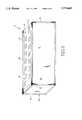
- FIG. 1is a perspective view of a page-wide-array (“PWA”) printer element
- FIG. 2is a nozzle group of the PWA printer element of FIG. 1;
- FIG. 3is a nozzle structure of a nozzle of FIG. 2;
- FIG. 4is planar view of a media sheet moving relative to a PWA printhead and velocity sensor according to one embodiment of this invention
- FIG. 5is planar view of a media sheet moving relative to a PWA printhead and velocity sensor according to another embodiment of this invention.
- FIG. 6is planar view of a media sheet moving relative to a PWA printhead and velocity sensor according to yet another embodiment of this invention.
- FIG. 7is a block diagram of printer electronics embodying the velocity feedback method according to one embodiment of this invention.
- FIG. 1shows an inkjet page-wide-array (“PWA") printer element 10.
- the printer element 10extends at least a pagewidth in length (e.g., 8.5", 11" or A4) and ejects liquid ink droplets onto a media sheet.
- the printer element 10is fixed.
- the media sheetis fed adjacent to a printhead surface 12 of the printer element 10 during printing.
- ink dropletsare ejected from printhead nozzles 44 (see FIGS. 2 and 3) to form markings representing characters or images.
- the PWA printhead 12prints one or more lines of dots at a time across the pagewidth.
- the printhead 12includes thousands of nozzles 44 across its length, but only select dots are activated at a given time to achieve the desired markings.
- an 11 inch printhead with 600 dpi resolutionhas at least 6600 nozzles.
- the printer element 10includes a printbar 14, a flexible printed circuit ("flex circuit") 16, and nozzle circuitry (FIGS. 3 and 7).
- the printhead 12is formed by a first surface 22, the nozzle circuitry and the flex circuit 16.
- the printbar 14serves as the printer element 10 body to which the other components are attached. In one embodiment the printbar 14 is approximately 12.5" by 1" by 2.5" and defines the first surface 22 to be approximately 12.5" by 1".
- the printbar 14also defines an internal chamber 23 for holding an ink supply. In some embodiments the chamber 23 serves as a resident reservoir connected to an external ink source located within the printer but separate from the printer element 10.
- the flex circuit 16is a printed circuit made of a flexible base material having multiple conductive paths and a peripheral connector. Conductive paths run from the peripheral connector to various nozzle groups 26 and from nozzle group 26 to nozzle group 26.
- the flex circuit 16is formed from a base material made of polyamide or other flexible polymer material (e.g., polyester, poly-methyl-methacrylate) and conductive paths made of copper, gold or other conductive material.
- the flex circuit 16 with only the base material and conductive pathsis available from the 3M Company of Minneapolis, Minn.
- the nozzle groups 26 and peripheral connectorthen are added.
- the flex circuit 16is coupled to off-circuit electronics via an edge connector or button connector.
- FIG. 2is a diagram of a nozzle group 26.
- Each nozzle group 26includes two rows 40, 42 of printhead nozzles 44. Flex circuit conductors meet with nozzle group conductors to define a circuit path. In one embodiment for an 11 inch printhead 12 with 600 dpi resolution, there are 32 nozzle groups 26, and sixteen groups 26 per row 53, 60. Each group extends approximately 0.5 inches and is offset from adjacent groups 26 in the other row.
- Each nozzle groupincludes two rows 42, 44 of printhead nozzles 44. Each row includes at least 150 printhead nozzles 44. The nozzles 44 in a given row 42(44) are staggered or precisely aligned.
- nozzles 44 in all rows 42(44) for all nozzle groups 26 of a row 53(60)are staggered or precisely aligned.
- the substrate 49defines memory and nozzle circuitry.
- the memoryis loaded with dot data from off-circuit print memory (e.g., memory on print process or board or an add-in card).
- the nozzle circuitryincludes a switch for receiving a firing signal from the memory. When the firing signal is active the switch excites a resistor, which in turn heats up ink within a nozzle chamber. Some of the ink vaporizes. Some of the ink is displaced so as to be ejected a droplet having a known repeatable volume and shape.
- FIG. 3shows a printhead nozzle 44 loaded with ink I.
- a silicon substrate 49 with additional layersdefines one or more nozzle groups 26 attached to the printbar 14 and flex circuit 26.
- a nozzle 44receives ink I from a printbar reservoir via a channel 54.
- the inkflows into a nozzle chamber 52.
- the nozzle chamber 52is defined by a barrier film 56, a nozzle plate 58 and a passivation layer 60.
- Additional layersare formed between the substrate 49 and passivation layer 60, including insulative layers 62, 64, another passivation layer 66 and a conductive film layer 68.
- the conductive film layer 68defines a firing resistor 50.
- the nozzle plate 58is mounted to the flex circuit 26 with the nozzle circuitry. In another embodiment the flex circuit forms the nozzle plate 58. According to the flex circuit embodiment for the nozzle plate 58, respective orifices are laser drilled to achieve a precise area, orientation and position relative to the nozzle chambers 52. The nozzle orifice has a uniform diameter for each nozzle. In various embodiments the nozzle orifice is 10-50 microns in diameter.
- the substrate 49typically defines nozzle and memory circuitry for several nozzles.
- a substratedefines nozzle and memory circuitry for a given nozzle group 26.
- a substratedefines the same for multiple nozzle groups 26 (e.g., all groups 26; all groups 26 in a row 53, 60; some groups in one or more rows 53, 60).
- FIGS. 4-6show a media sheet M moving relative to the PWA printer element 10 and velocity sensor 80 in a transport direction 82 according to three alternate embodiments of this invention.
- the sensor 80is positioned on the printer element 10 at side 30 so that the sensor 80 detects the velocity of the media sheet M as it passes beyond the element 10.
- the sensor 80is positioned on the printer element 10 at side 28 so that the sensor 80 detects velocity of the media sheet M as it first encounters the printer element 10.
- the sensor 80is mounted apart from the printer element 10 at a position directly beneath the printer element 10. The media sheet travels between the sensor 80 and printer element 10 so that sensor 80 detects the velocity of the media sheet M as the sheet M passes below the nozzle groups 26.
- the velocity sensor 80is an electro-optic paper positioning sensor or sensor array adapted for deriving the rate of media movement.
- Such optical sensor(s)are described in U.S. Pat. No. 5,089,712, issued Feb. 18, 1992 for Sheet Advancement Control System Detecting Fiber Pattern of Sheet; and U.S. Pat. No. 5,149,980 issued Sep. 22, 1992 for Substrate Advance Measurement System Using Cross-Correlation of Light Sensor Array Signals.
- the sensor(s) 80include a respective light source and light detector. The sensor looks at the media fiber, then develops a signature, then monitors the movement of the signature.
- exemplary light sourcesinclude a photo-emitter, LED, laser diode, super luminescent diode, or fiber optic source.
- exemplary light detectorsinclude a photo-detector, charged couple device, or photodiode. The light source is oriented to emit a light beam in a specific direction relative to the printer element 10. The light detector is aligned to detect light reflected from the media sheet.
- Dot dataas used herein means a data format corresponding to the dot pattern to be printed to achieve media sheet markings corresponding to given input data.
- Dot data for a given nozzle 44is one bit having a first logic state indicating the nozzle is to fire ink or a second logic state indicating the nozzle is not to fire ink.
- the dot datadefines lines of output dots. Each line of dot data corresponds to the firing state of each of the approximately 6600 nozzles for a given time.
- a current dot linewill have approximately 6600 entries with between 0 and 6600 of the entries having a first logic state indicating to fire a corresponding nozzle. If all 6600 entries are at the first logic state, then a solid line is printed. If 1 or more but less than the 6600 entries have a first logic state, then the printed output appears as a dot, one or more line segments and/or dots, or a lighter line.
- dot data for 6600 entries or moreare periodically transferred from printer memory to printbar memory 70 according to a serial or parallel data transfer protocol.
- memory 70stores one line at a time. In other embodiments, memory 70 has look-ahead capacity for storing multiple lines at a time.
- Dot data from printbar memory 70then is output to the flex circuit 16 and nozzle groups 26 to activate nozzles 44. In particular the dot data are input to an array 88 of firing switches.
- dot datais output in pluralities to address a plurality of nozzles 44 at a time (e.g., nozzle group by nozzle group or another addressing scheme for selecting less than all nozzles at a time).
- printer element 10lacks printbar memory 70.
- dot datais transferred directly from printer memory 84 to the flex circuit 16 and nozzle groups 26 (e.g., switch array 88) to address pluralities of nozzles 44.
- printer element 10includes memory 70 positioned on the printbar 14. Dot data is received from print memory 84, then output from printbar memory 70 to the firing switch array 88 preferably in parallel multiplexed fashion.
- a printhead controller 90defines the timing for activating switches of array 88, and thus, for firing nozzles 44.
- the controller 90is timing circuitry on the flex circuit 16, substrate 49 or printbar 14.
- the controller 90is embodied by the print processor 86.
- the printhead controller 90determines timing for transferring data from printer memory 84 into printbar memory 70 and from printbar memory 70 to the switch array 88. In the embodiment without printbar memory 70, print controller 90 determines timing for transferring data from printer memory 84 to the switch array 88.
- the switchesfirst are disabled. Dot data for select nozzles 44 then are output to the array 88. The corresponding switches then are enabled causing the switches to drive their corresponding firing resistors 50. The firing resistors 50 heat the ink within respective nozzle chambers 52 causing ink droplets to be fired. The switches then are disabled. The cycle then repeats for another set of nozzles 44 until all nozzles have been addressed. The process repeats for all the nozzles 44 again and again as the print job continues. Such process typically occurs at a "set" frequency during a print job. However, according to the method of this invention, the frequency is adjustable.
- the set frequencydefines a rated timing.
- Such rated timingis derived for a known constant velocity of paper motion relative to the printer element 10.
- Such known constant velocityis referred to herein as a rated velocity.
- Exemplary rated constant velocitiesrange from 1 page per minute upward. Speeds are of 1 inch per second to 100 inches per second are typical.
- controller 90generates timing signals for the approximately 6600 nozzles 44 at an approximately 20 kHz nozzle speed. To be within a 1/4 dot tolerance all 6600 nozzle are addressed within 12.5 microseconds. In a specific embodiment, a set of 30 nozzles is addressed at a time. Different sets are addressed in sequence until all 6600 nozzles have been addressed within the 12.5 microseconds.
- media sheet M velocityis detected and compared to the rated constant velocity.
- Sensor 80periodically samples the media sheet M velocity to maintain print accuracy within a 1/4 dot tolerance for a print speed equal to the nozzle speed (e.g., 20 kHz).
- An acceptable range of sampling ratevaries according to print speed and media transport motor linearity. For a very fast print speed of 100 inches per second the maximum needed sampling rate for a motor with no more than 1% velocity variation in 0.003 seconds is 30 kHz. Thus, sampling at more than 30 kHz is effective for typical low cost transport motors and very fast print speeds. As print speed typically is lower and motor linearity truer, other embodiments may use slower sampling rates. Because a sampling frequency of 30 kHz or less is such a small processing burden faster sampling rates are used in many embodiments.
- the sampled sheet M velocityis input to the print controller 90.
- the print controller 90compares the measured "actual" velocity to the "rated" constant velocity.
- the rated constant velocityis the known velocity used for defining the normal or rated timing signal frequency. For actual velocities less than the rated velocity the frequency of the timing signal is decreased.
- the adjusted frequencyis determined by the relationship (I) below:
- f 1adjusted frequency
- the print controller 90includes an adjustable clock with a programmable delay line defining the clock frequency. The delay is varied according to the outcome of relationship (I). In one embodiment, a change in delay time is derived from the derived frequency and the rated frequency based upon the relationship (II) below:
- a media sheet Mis picked from a media stack and moved along a media path by a media transport subsystem.
- a transport subsystemtypically includes a series or drive rollers along with a biasing element for pressing the sheet M to the rollers.
- a transport motorruns the drive rollers.
- the media sheet Maccelerates from rest up to a constant velocity. Such constant velocity is consistent from cycle to cycle and serves as a rated velocity for the PWA printer. Because the printhead prints while the media sheet is moving, the rated velocity is used to define a rated timing signal so that dots are accurately placed on the media sheet M. According to the method of this invention, printing can occur even while the media sheet M is accelerating or moving at other than the rated velocity. Actual velocity is measured and used to adjust the timing so that dots still are accurately placed on the media sheet M.
- One advantage of the inventionis that down time while waiting for the media sheet to speed up to a constant velocity is avoided.
- the PWA printhead nozzle timingis adjusted to print while the media sheet accelerates to the constant velocity.
- the time to complete a print jobis less.
- Another advantageis that the media path can be shorter because the printer element can be positioned closer to the paper stack.
- a beneficial effectis that the footprint can be smaller (e.g., approximately 17 inches instead of 28 inches).
Landscapes
- Ink Jet (AREA)
- Particle Formation And Scattering Control In Inkjet Printers (AREA)
Abstract
Description
This invention is related to U.S. patent application Ser. No. 08/375,754 filed on Jan. 20, 1995 for Kinematically Fixing Flex Circuit to PWA Printbar (Docket No. 191044-1), and U.S. patent application Ser. No. 08/376,320 filed on Jan. 20, 1995 for PWA Inkjet Print Element With Resident Memory (Docket No. 191041), which applications are incorporated herein by reference and made a part hereof. This invention also is related to U.S. Pat. No. 5,089,712, issued Feb. 18, 1992 for Sheet Advancement Control System Detecting Fiber Pattern of Sheet (Holland);column 2,line 54 to column 5, line 55 of which are incorporated herein by reference and made a part hereof.
This invention relates generally to page-wide-array ("PWA") inkjet printing methods, and more particularly, to a method of using media velocity feedback to vary PWA inkjet nozzle timing.
A PWA inkjet printer includes a printer element defining a page-wide-array printhead with thousands of nozzles. For an 11 inch printhead printing at 600 dpi, there are at least 6600 nozzles along the printhead. Ink is delivered from a resident reservoir to a nozzle chamber of each nozzle. During operation, the printer element is fixed while a page is fed adjacent to the printhead by a media handling subsystem. When printing, a firing resistor within a nozzle chamber is activated so as to heat the ink therein and cause a vapor bubble to form. The vapor bubble then ejects the ink as a droplet. Droplets of repeatable velocity and volume are ejected from respective nozzles to effectively imprint characters and graphic markings onto a media sheet. The PWA printhead prints one or more lines at a time as the page moves relative to the printhead.
Previous inkjet printers have used scanning type pen bodies. The scanning type pen bodies scan across a page while the page is intermittently moved by a media handling subsystem. A PWA printer element is analogous to the pen body, but has more nozzles and is fixed. A PWA printer element includes more than 5,000 nozzles extending the length of a pagewidth, while that of a conventional pen body has approximately 100-200 nozzles extending a distance of approximately 0.15 to 0.50 inches.
One of the driving motivations for creating a page-wide-array printhead is to achieve faster printing speeds. In particular it is desirable that a PWA printhead run at a print speed approaching nozzle speed. Nozzle speed is the highest frequency at which a nozzle is capable of firing as limited by nozzle technology. Print speed is the frequency at which nozzles are fired during a print operation. Print speed typically is less than nozzle speed due to limitations in data handling (i.e., data throughput) and media handling. With more nozzles the PWA printer element should print much faster than a smaller scanning pen body. One challenge of page-wide-array printing is to assure that dot data is available at each nozzle in a timely fashion. With thousands more nozzles than a conventional scanning pen body, such data throughput challenge is significant. The commonly-assigned patent application, "PWA Inkjet Printer Element with Resident Memory," referenced above and included herein by reference, addresses the data throughput problem by including memory on the printbar.
This application addresses an aspect of the media handling problem. Print speed often is compromised by the media transport system. For example, for printing with conventional scanning pen bodies, a media sheet is moved into position and stopped. Then the pen body scans the media to print a line of dots. The media sheet then is moved slightly along the media path to a new position. The pen body then scans the media again to print another line of dots. The cycle repeats for the entire print operation. One approach for improving print speed is to move the media while dots are printed. In particular, one approach would be to print while the media sheet moves at a constant velocity. Under such approach, however, there is a delay while the media sheet accelerates from rest up to the constant velocity. In addition, the media path would need to be longer to provide a path during the acceleration. Accordingly, there is a need for a printer element that can print with desired accuracy onto a media sheet moving at either a constant or non-constant velocity.
According to the invention, a page-wide-array ("PWA") printer element prints dots while a media sheet is in motion. A media sheet is moved from a stack along a media path by a media handling subsystem. As the sheet moves adjacent to the PWA printhead, nozzles are fired to eject ink droplets onto the media sheet.
According to one aspect of the invention, firing of printhead nozzles is controlled as a function of media speed. A media sheet accelerates from rest up to a known substantially constant velocity. Nozzles are fired while the media sheet accelerates and continue to fire while the media sheet moves at constant velocity. Nozzle timing is adjusted during acceleration to achieve accurate dot placement on the media sheet.
According to another aspect of the invention, nozzle timing has a "rated" timing for firing nozzles while the media sheet moves at a rated "constant" velocity. The rated constant velocity is the constant velocity achieved by the media sheet while moving along the media path. Variations in actual velocity relative to the rated velocity are used to adjust nozzle timing.
According to another aspect of the invention, a sensor is fixed relative to a PWA printer element for detecting a media sheet's actual velocity. Actual velocity is compared to the rated velocity. If actual velocity is slower than the rated velocity, then nozzle timing is adjusted to be slower than the rated timing. If actual velocity is faster than rated velocity, then nozzle timing is adjusted to be faster than the rated timing. As a media sheet is transported from a media stack then along a media path, its velocity typically accelerates from 0 up to the rated velocity, then remains at the rated velocity. Thus, the timing initially is adjusted to be substantially slower than the rated timing. Gradually the timing is increased to approach the rated timing. For a reliable media transport system, the media sheet will consistently reach and maintain the same constant velocity, (i.e., the rated velocity). Thus, in practice the timing is adjusted to reach, then hold at the rated timing.
According to another aspect of the invention, the actual velocity is sensed accurately enough for the adjusted timing to control dot printing within a 1/4 dot tolerance error. For 600 dpi resolution, 1/4 dot tolerance is 1/2400 inches. For 600 dpi resolution, velocity measurements sampled at lower than 30 kHz correct the nozzle timing often enough for printing within the 1/4 dot tolerance.
One advantage of the invention is that previous down time while starting and stopping a media sheet is avoided. Another advantage is that down time while waiting for the media sheet to reach a constant velocity is avoided. The PWA printhead nozzle timing is adjusted to prim while the media sheet is moving, and even while the media sheet accelerates up to a constant velocity. Another advantage is that the media path can be shorter because the printer element can be positioned closer to the paper stack. A beneficial effect is that the footprint can be smaller (e.g., approximately 17 inches instead of 28 inches).
These and other aspects and advantages of the invention will be better understood by reference to the following detailed description taken in conjunction with the accompanying drawings.
FIG. 1 is a perspective view of a page-wide-array ("PWA") printer element;
FIG. 2 is a nozzle group of the PWA printer element of FIG. 1;
FIG. 3 is a nozzle structure of a nozzle of FIG. 2;
FIG. 4 is planar view of a media sheet moving relative to a PWA printhead and velocity sensor according to one embodiment of this invention;
FIG. 5 is planar view of a media sheet moving relative to a PWA printhead and velocity sensor according to another embodiment of this invention;
FIG. 6 is planar view of a media sheet moving relative to a PWA printhead and velocity sensor according to yet another embodiment of this invention; and
FIG. 7 is a block diagram of printer electronics embodying the velocity feedback method according to one embodiment of this invention.
Inkjet PWA Printer Element
FIG. 1 shows an inkjet page-wide-array ("PWA")printer element 10. Theprinter element 10 extends at least a pagewidth in length (e.g., 8.5", 11" or A4) and ejects liquid ink droplets onto a media sheet. When installed in an inkjet printer, theprinter element 10 is fixed. The media sheet is fed adjacent to aprinthead surface 12 of theprinter element 10 during printing. As the media sheet moves relative to thePWA printhead 12, ink droplets are ejected from printhead nozzles 44 (see FIGS. 2 and 3) to form markings representing characters or images. ThePWA printhead 12 prints one or more lines of dots at a time across the pagewidth. Theprinthead 12 includes thousands ofnozzles 44 across its length, but only select dots are activated at a given time to achieve the desired markings. A solid line for example, would be printed using all nozzles located between the endpoints of such line. In one embodiment an 11 inch printhead with 600 dpi resolution has at least 6600 nozzles.
In one embodiment theprinter element 10 includes aprintbar 14, a flexible printed circuit ("flex circuit") 16, and nozzle circuitry (FIGS. 3 and 7). Theprinthead 12 is formed by a first surface 22, the nozzle circuitry and theflex circuit 16. Theprintbar 14 serves as theprinter element 10 body to which the other components are attached. In one embodiment theprintbar 14 is approximately 12.5" by 1" by 2.5" and defines the first surface 22 to be approximately 12.5" by 1". Theprintbar 14 also defines aninternal chamber 23 for holding an ink supply. In some embodiments thechamber 23 serves as a resident reservoir connected to an external ink source located within the printer but separate from theprinter element 10.
Attached to theprintbar 14 at the first surface 22 is theflex circuit 16. Theflex circuit 16 is a printed circuit made of a flexible base material having multiple conductive paths and a peripheral connector. Conductive paths run from the peripheral connector tovarious nozzle groups 26 and fromnozzle group 26 tonozzle group 26. In one embodiment theflex circuit 16 is formed from a base material made of polyamide or other flexible polymer material (e.g., polyester, poly-methyl-methacrylate) and conductive paths made of copper, gold or other conductive material. Theflex circuit 16 with only the base material and conductive paths is available from the 3M Company of Minneapolis, Minn. Thenozzle groups 26 and peripheral connector then are added. Theflex circuit 16 is coupled to off-circuit electronics via an edge connector or button connector.
FIG. 2 is a diagram of anozzle group 26. Eachnozzle group 26 includes tworows printhead nozzles 44. Flex circuit conductors meet with nozzle group conductors to define a circuit path. In one embodiment for an 11inch printhead 12 with 600 dpi resolution, there are 32nozzle groups 26, and sixteengroups 26 perrow adjacent groups 26 in the other row. Each nozzle group includes tworows printhead nozzles 44. Each row includes at least 150printhead nozzles 44. Thenozzles 44 in a given row 42(44) are staggered or precisely aligned. Further thenozzles 44 in all rows 42(44) for allnozzle groups 26 of a row 53(60) are staggered or precisely aligned. Thus, there are four lines ofnozzles 44 on theprinthead 12 used for printing one line of approximately 6600 dots.
In one embodiment, thesubstrate 49 defines memory and nozzle circuitry. The memory is loaded with dot data from off-circuit print memory (e.g., memory on print process or board or an add-in card). The nozzle circuitry includes a switch for receiving a firing signal from the memory. When the firing signal is active the switch excites a resistor, which in turn heats up ink within a nozzle chamber. Some of the ink vaporizes. Some of the ink is displaced so as to be ejected a droplet having a known repeatable volume and shape.
FIG. 3 shows aprinthead nozzle 44 loaded with ink I. In one embodiment asilicon substrate 49 with additional layers defines one ormore nozzle groups 26 attached to theprintbar 14 andflex circuit 26. Anozzle 44 receives ink I from a printbar reservoir via achannel 54. The ink flows into anozzle chamber 52. Thenozzle chamber 52 is defined by abarrier film 56, anozzle plate 58 and apassivation layer 60. Additional layers are formed between thesubstrate 49 andpassivation layer 60, includinginsulative layers passivation layer 66 and aconductive film layer 68. Theconductive film layer 68 defines a firingresistor 50.
In one embodiment thenozzle plate 58 is mounted to theflex circuit 26 with the nozzle circuitry. In another embodiment the flex circuit forms thenozzle plate 58. According to the flex circuit embodiment for thenozzle plate 58, respective orifices are laser drilled to achieve a precise area, orientation and position relative to thenozzle chambers 52. The nozzle orifice has a uniform diameter for each nozzle. In various embodiments the nozzle orifice is 10-50 microns in diameter.
Thesubstrate 49 typically defines nozzle and memory circuitry for several nozzles. In one embodiment a substrate defines nozzle and memory circuitry for a givennozzle group 26. In another embodiment a substrate defines the same for multiple nozzle groups 26 (e.g., allgroups 26; allgroups 26 in arow more rows 53, 60).
Media Handling and Velocity Sensor
FIGS. 4-6 show a media sheet M moving relative to thePWA printer element 10 andvelocity sensor 80 in atransport direction 82 according to three alternate embodiments of this invention. In the embodiment shown in FIG. 4, thesensor 80 is positioned on theprinter element 10 atside 30 so that thesensor 80 detects the velocity of the media sheet M as it passes beyond theelement 10. In the embodiment shown in FIG. 5, thesensor 80 is positioned on theprinter element 10 atside 28 so that thesensor 80 detects velocity of the media sheet M as it first encounters theprinter element 10. In the embodiment shown in FIG. 6, thesensor 80 is mounted apart from theprinter element 10 at a position directly beneath theprinter element 10. The media sheet travels between thesensor 80 andprinter element 10 so thatsensor 80 detects the velocity of the media sheet M as the sheet M passes below the nozzle groups 26.
According to one embodiment of the invention thevelocity sensor 80 is an electro-optic paper positioning sensor or sensor array adapted for deriving the rate of media movement. Such optical sensor(s) are described in U.S. Pat. No. 5,089,712, issued Feb. 18, 1992 for Sheet Advancement Control System Detecting Fiber Pattern of Sheet; and U.S. Pat. No. 5,149,980 issued Sep. 22, 1992 for Substrate Advance Measurement System Using Cross-Correlation of Light Sensor Array Signals. The sensor(s) 80 include a respective light source and light detector. The sensor looks at the media fiber, then develops a signature, then monitors the movement of the signature.
According to various optical sensor embodiments, exemplary light sources include a photo-emitter, LED, laser diode, super luminescent diode, or fiber optic source. Exemplary light detectors include a photo-detector, charged couple device, or photodiode. The light source is oriented to emit a light beam in a specific direction relative to theprinter element 10. The light detector is aligned to detect light reflected from the media sheet.
Dot Data
During a normal print job, image data, text data or data of another format is output from a host computer to printer memory 84 (See FIG. 7) of a PWA inkjet printer. Aprint processor 86 converts the received data into "dot data." Dot data as used herein means a data format corresponding to the dot pattern to be printed to achieve media sheet markings corresponding to given input data. Dot data for a givennozzle 44 is one bit having a first logic state indicating the nozzle is to fire ink or a second logic state indicating the nozzle is not to fire ink. The dot data defines lines of output dots. Each line of dot data corresponds to the firing state of each of the approximately 6600 nozzles for a given time. A current dot line will have approximately 6600 entries with between 0 and 6600 of the entries having a first logic state indicating to fire a corresponding nozzle. If all 6600 entries are at the first logic state, then a solid line is printed. If 1 or more but less than the 6600 entries have a first logic state, then the printed output appears as a dot, one or more line segments and/or dots, or a lighter line.
For a 6600 nozzle embodiment, dot data for 6600 entries or more are periodically transferred from printer memory toprintbar memory 70 according to a serial or parallel data transfer protocol. In oneembodiment memory 70 stores one line at a time. In other embodiments,memory 70 has look-ahead capacity for storing multiple lines at a time. Dot data fromprintbar memory 70 then is output to theflex circuit 16 andnozzle groups 26 to activatenozzles 44. In particular the dot data are input to anarray 88 of firing switches. In one embodiment, dot data is output in pluralities to address a plurality ofnozzles 44 at a time (e.g., nozzle group by nozzle group or another addressing scheme for selecting less than all nozzles at a time).
In oneembodiment printer element 10 lacksprintbar memory 70. For such embodiment, dot data is transferred directly fromprinter memory 84 to theflex circuit 16 and nozzle groups 26 (e.g., switch array 88) to address pluralities ofnozzles 44. In anotherembodiment printer element 10 includesmemory 70 positioned on theprintbar 14. Dot data is received fromprint memory 84, then output fromprintbar memory 70 to thefiring switch array 88 preferably in parallel multiplexed fashion.
Nozzle Timing
Aprinthead controller 90 defines the timing for activating switches ofarray 88, and thus, for firingnozzles 44. In one embodiment, thecontroller 90 is timing circuitry on theflex circuit 16,substrate 49 orprintbar 14. In another embodiment thecontroller 90 is embodied by theprint processor 86. Theprinthead controller 90 determines timing for transferring data fromprinter memory 84 intoprintbar memory 70 and fromprintbar memory 70 to theswitch array 88. In the embodiment withoutprintbar memory 70,print controller 90 determines timing for transferring data fromprinter memory 84 to theswitch array 88.
According to one method for firing switches inarray 88, the switches first are disabled. Dot data forselect nozzles 44 then are output to thearray 88. The corresponding switches then are enabled causing the switches to drive their correspondingfiring resistors 50. The firingresistors 50 heat the ink withinrespective nozzle chambers 52 causing ink droplets to be fired. The switches then are disabled. The cycle then repeats for another set ofnozzles 44 until all nozzles have been addressed. The process repeats for all thenozzles 44 again and again as the print job continues. Such process typically occurs at a "set" frequency during a print job. However, according to the method of this invention, the frequency is adjustable.
The set frequency defines a rated timing. Such rated timing is derived for a known constant velocity of paper motion relative to theprinter element 10. Such known constant velocity is referred to herein as a rated velocity. Exemplary rated constant velocities range from 1 page per minute upward. Speeds are of 1 inch per second to 100 inches per second are typical. In oneembodiment controller 90 generates timing signals for the approximately 6600nozzles 44 at an approximately 20 kHz nozzle speed. To be within a 1/4 dot tolerance all 6600 nozzle are addressed within 12.5 microseconds. In a specific embodiment, a set of 30 nozzles is addressed at a time. Different sets are addressed in sequence until all 6600 nozzles have been addressed within the 12.5 microseconds. To achieve such addressing a transfer rate fromprintbar memory 70 to switcharray 88 of3 17.6 MHz (i.e., 4.4 MHz×4) is used. By increasing the number of nozzles in a set, and thus addressed at one time, the 17.6 MHz rated timing can be reduced while still maintaining a 20 kHz nozzle speed and 1/4 dot tolerance error.
Velocity Feedback
According to the velocity feedback method of this invention, media sheet M velocity is detected and compared to the rated constant velocity.Sensor 80 periodically samples the media sheet M velocity to maintain print accuracy within a 1/4 dot tolerance for a print speed equal to the nozzle speed (e.g., 20 kHz). An acceptable range of sampling rate varies according to print speed and media transport motor linearity. For a very fast print speed of 100 inches per second the maximum needed sampling rate for a motor with no more than 1% velocity variation in 0.003 seconds is 30 kHz. Thus, sampling at more than 30 kHz is effective for typical low cost transport motors and very fast print speeds. As print speed typically is lower and motor linearity truer, other embodiments may use slower sampling rates. Because a sampling frequency of 30 kHz or less is such a small processing burden faster sampling rates are used in many embodiments.
The sampled sheet M velocity is input to theprint controller 90. Theprint controller 90 compares the measured "actual" velocity to the "rated" constant velocity. The rated constant velocity is the known velocity used for defining the normal or rated timing signal frequency. For actual velocities less than the rated velocity the frequency of the timing signal is decreased. The adjusted frequency is determined by the relationship (I) below:
f.sub.1 /f.sub.0 =v.sub.1 /v.sub.0 (I)
where
f1 =adjusted frequency;
f0 =rated frequency;
v1 =actual velocity; and
v0 =rated velocity.
Rated frequency and rated velocity are known. Actual velocity is measured. Thus, adjusted frequency is derived. In one embodiment, theprint controller 90 includes an adjustable clock with a programmable delay line defining the clock frequency. The delay is varied according to the outcome of relationship (I). In one embodiment, a change in delay time is derived from the derived frequency and the rated frequency based upon the relationship (II) below:
delta t=t.sub.1 -t.sub.0 (II)
where
t0 =delay for rated frequency; and
t1 =t0 *(f1 /f0).
Typically, a media sheet M is picked from a media stack and moved along a media path by a media transport subsystem. Such a transport subsystem typically includes a series or drive rollers along with a biasing element for pressing the sheet M to the rollers. A transport motor runs the drive rollers. The media sheet M accelerates from rest up to a constant velocity. Such constant velocity is consistent from cycle to cycle and serves as a rated velocity for the PWA printer. Because the printhead prints while the media sheet is moving, the rated velocity is used to define a rated timing signal so that dots are accurately placed on the media sheet M. According to the method of this invention, printing can occur even while the media sheet M is accelerating or moving at other than the rated velocity. Actual velocity is measured and used to adjust the timing so that dots still are accurately placed on the media sheet M.
Meritorious and Advantageous Effects
One advantage of the invention is that down time while waiting for the media sheet to speed up to a constant velocity is avoided. The PWA printhead nozzle timing is adjusted to print while the media sheet accelerates to the constant velocity. Thus, the time to complete a print job is less. Another advantage is that the media path can be shorter because the printer element can be positioned closer to the paper stack. A beneficial effect is that the footprint can be smaller (e.g., approximately 17 inches instead of 28 inches).
Although a preferred embodiment of the invention has been illustrated and described, various alternatives, modifications and equivalents may be used. Therefore, the foregoing description should not be taken as limiting the scope of the inventions which are defined by the appended claims.
Claims (12)
1. A method for adjusting a timing signal that controls nozzle firing for a page-wide-array printer element, comprising the steps of:
accelerating a media sheet from rest up to a constant velocity approximating a rated velocity as the media sheet moves along a media path, the media sheet increasing velocity while a page-wide-array printhead of nozzles ejects ink onto the media sheet;
generating a timing signal for addressing a first plurality of nozzles on the page-wide-array printhead of nozzles, at least one of the addressed nozzles ejecting ink onto the media sheet;
detecting actual velocity of the media sheet in the vicinity of the printhead with a velocity sensing apparatus; and
periodically adjusting frequency of the timing signal as a function of the actual velocity and the rated velocity, wherein the rated velocity is fixed.
2. The method of claim 1 in which the velocity sensing apparatus is positioned on the printer element upstream from the printhead relative to the media path.
3. The method of claim 1 in which the velocity sensing apparatus is positioned on the printer element downstream from the printhead relative to the media path.
4. The method of claim 1 in which the velocity sensing apparatus and printer element are aligned along the media path so that actual velocity is sampled for a portion of the media sheet passing adjacent to the printhead, such portion passing between the velocity sensing apparatus and printhead.
5. An apparatus for adjusting a nozzle timing signal while a media sheet accelerates along a media path up to a constant velocity approximating a rated velocity, the media sheet increasing velocity while a page-wide-array printhead of nozzles ejects ink onto the media sheet, the apparatus comprising:
a velocity sensor for detecting actual velocity of the media sheet in the vicinity of the printhead;
a timing generator for defining a timing signal for activating at least one of a first plurality of the page-wide-array of nozzles to eject ink onto the media sheet; and
means for periodically adjusting frequency of the timing signal as a function of the actual velocity and the rated velocity, wherein the rated velocity is fixed.
6. The apparatus of claim 5 in which the velocity sensing apparatus is positioned upstream from the printhead relative to the media path.
7. The apparatus of claim 5 in which the velocity sensing apparatus is positioned downstream from the printhead relative to the media path.
8. The apparatus of claim 5 in which the velocity sensing apparatus and printhead are aligned along the media path so that actual velocity is sampled for a portion of the media sheet passing adjacent to the printhead, such portion passing between the velocity sensing apparatus and printhead.
9. A page-wide-array inkjet printing apparatus for adjusting a nozzle timing signal while a media sheet accelerates along a media path up to a constant velocity approximating a rated velocity, the media sheet increasing velocity while a page-wide-array printhead of nozzles ejects ink onto the media sheet, the apparatus comprising:
an elongated printbar for defining a printbar chamber for holding ink and defining a first surface;
a plurality of nozzle circuits, each one of said nozzle circuits defining a nozzle chamber for receiving ink from the printbar chamber and a firing resistor within the nozzle chamber;
a flex circuit defining a plurality of conductive paths, wherein the plurality of nozzle circuits are attached to the flex circuit and wherein each one of the conductive paths is electronically coupled to a firing resistor of a corresponding one of the nozzle circuits, and wherein the flex circuit with attached nozzle circuits are attached to the first surface of the printbar to define the page-wide-array printhead of nozzles;
memory for storing dot data for each one of the printhead nozzles, wherein dot data for each one of the printhead nozzles is output from memory to the firing resistor of a corresponding one of the printhead nozzles;
a velocity sensor for detecting actual velocity of the media sheet in the vicinity of the printhead;
a timing generator for defining a timing signal for activating one or more of a first plurality of the printhead nozzles to eject ink onto the media sheet; and
means for periodically adjusting frequency of the timing signal as a function of the actual velocity and the rated velocity, wherein the rated velocity is fixed.
10. The apparatus of claim 9 in which the velocity sensing apparatus is positioned on the printer element upstream from the printhead relative to the media path.
11. The apparatus of claim 9 in which the velocity sensing apparatus is positioned on the printer element downstream from the printhead relative to the media path.
12. The apparatus of claim 9 in which the velocity sensing apparatus and printer element are aligned along the media path so that actual velocity is sampled for a portion of the media sheet passing adjacent to the printhead, such portion passing between the velocity sensing apparatus and printhead.
Priority Applications (3)
| Application Number | Priority Date | Filing Date | Title |
|---|---|---|---|
| US08/375,743US5719602A (en) | 1995-01-20 | 1995-01-20 | Controlling PWA inkjet nozzle timing as a function of media speed |
| JP8006822AJPH08230194A (en) | 1995-01-20 | 1996-01-18 | Nozzle jet control method |
| KR1019960001111AKR100358637B1 (en) | 1995-01-20 | 1996-01-19 | Controlling pwa inkjet nozzle timing as a fuction of media speed |
Applications Claiming Priority (1)
| Application Number | Priority Date | Filing Date | Title |
|---|---|---|---|
| US08/375,743US5719602A (en) | 1995-01-20 | 1995-01-20 | Controlling PWA inkjet nozzle timing as a function of media speed |
Publications (1)
| Publication Number | Publication Date |
|---|---|
| US5719602Atrue US5719602A (en) | 1998-02-17 |
Family
ID=23482147
Family Applications (1)
| Application Number | Title | Priority Date | Filing Date |
|---|---|---|---|
| US08/375,743Expired - LifetimeUS5719602A (en) | 1995-01-20 | 1995-01-20 | Controlling PWA inkjet nozzle timing as a function of media speed |
Country Status (3)
| Country | Link |
|---|---|
| US (1) | US5719602A (en) |
| JP (1) | JPH08230194A (en) |
| KR (1) | KR100358637B1 (en) |
Cited By (78)
| Publication number | Priority date | Publication date | Assignee | Title |
|---|---|---|---|---|
| EP0996276A2 (en) | 1998-10-23 | 2000-04-26 | Hewlett-Packard Company | Dry erase electronic whiteboard with page-wide-array inkjet printer |
| US6113231A (en)* | 1998-02-25 | 2000-09-05 | Xerox Corporation | Phase change ink printing architecture suitable for high speed imaging |
| EP1034933A1 (en)* | 1999-03-09 | 2000-09-13 | Richard Gardiner | An inkjet printer printing responsive to substrate movement |
| WO2000054973A1 (en)* | 1999-03-16 | 2000-09-21 | Silverbrook Research Pty. Ltd. | Pagewidth wide format printer |
| US6239817B1 (en) | 1998-10-20 | 2001-05-29 | Hewlett-Packard Comapny | Apparatus and method for printing borderless print image |
| US20020057321A1 (en)* | 1998-09-29 | 2002-05-16 | Rasmussen Steve O. | Inkjet printing media handling system with advancing guide shim |
| DE10057061C1 (en)* | 2000-11-17 | 2002-05-23 | Koenig & Bauer Ag | Printing device e.g. for offset printing plate manufacture, uses ink jet printing heads positioned in spaced parallel rows |
| DE10057062C1 (en)* | 2000-11-17 | 2002-05-23 | Koenig & Bauer Ag | Printing head alignment method uses variation in printing head firing points and relative displacement of at least one printing head |
| WO2002040278A1 (en) | 2000-11-17 | 2002-05-23 | Koenig & Bauer Aktiengesellschaft | Printing devices comprising a plurality of print heads |
| US6402296B1 (en)* | 1998-10-29 | 2002-06-11 | Hewlett-Packard Company | High resolution inkjet printer |
| US6428224B1 (en) | 1999-12-21 | 2002-08-06 | Lexmark International, Inc. | Error mapping technique for a printer |
| US20020137363A1 (en)* | 1998-08-24 | 2002-09-26 | Thakur Randhir P.S. | Methods to form electronic devices |
| US6641251B1 (en) | 2002-07-15 | 2003-11-04 | Hewlett-Packard Development Company, Lp. | Printing system for printing in scan and print media feed directions and method of performing a printing operation |
| US20030227495A1 (en)* | 2002-06-07 | 2003-12-11 | Samii Mohammad M. | Fluid ejection and scanning assembly with photosensor activation of ejection elements |
| US20030227498A1 (en)* | 2002-06-07 | 2003-12-11 | Samii Mohammad M. | Fluid ejection system with photosensor activation of ejection element |
| US6672706B2 (en)* | 1997-07-15 | 2004-01-06 | Silverbrook Research Pty Ltd | Wide format pagewidth inkjet printer |
| US6679584B2 (en) | 1997-07-15 | 2004-01-20 | Silverbrook Research Pty Ltd. | High volume pagewidth printing |
| US20040027420A1 (en)* | 2002-06-07 | 2004-02-12 | Samii Mohammad M. | Photosensor activation of an ejection element of a fluid ejection device |
| US20040032471A1 (en)* | 1998-09-11 | 2004-02-19 | King Tobin Allen | Cartridge for a printing device |
| AU770374B2 (en)* | 1999-03-16 | 2004-02-19 | Memjet Technology Limited | Pagewidth wide format printer |
| US6695426B2 (en) | 2002-02-11 | 2004-02-24 | Lexmark International, Inc. | Ink jet printer improved dot placement technique |
| US6705701B2 (en) | 2002-06-07 | 2004-03-16 | Hewlett-Packard Development Company, L.P. | Fluid ejection and scanning system with photosensor activation of ejection elements |
| KR20040024016A (en)* | 2002-09-12 | 2004-03-20 | 삼성전자주식회사 | Image forming device and driving method thereof |
| US6747684B2 (en) | 2002-04-10 | 2004-06-08 | Hewlett-Packard Development Company, L.P. | Laser triggered inkjet firing |
| US20040135848A1 (en)* | 1997-07-15 | 2004-07-15 | Kia Silverbrook | Printing mechanism for a wide format pagewidth inkjet printer |
| US20040174408A1 (en)* | 2003-03-06 | 2004-09-09 | Hewlett-Packard Development Company, L.P. | Printer servicing system and method |
| US20040183843A1 (en)* | 2002-12-02 | 2004-09-23 | Walmsley Simon Robert | Compensation for uneven printhead module lengths in a multi-module printhead |
| US20040218003A1 (en)* | 2003-04-30 | 2004-11-04 | Hewlett-Packard Development Company, L.P. | Printing apparatus and method |
| US20050007418A1 (en)* | 1997-07-15 | 2005-01-13 | Kia Silverbrook | Printhead assembly arrangement for a wide format pagewidth inkjet printer |
| US6848779B2 (en)* | 2001-06-29 | 2005-02-01 | Hewlett-Packard Development Company, L.P. | Label-making inkjet printer |
| US6857724B2 (en) | 1997-07-15 | 2005-02-22 | Silverbrook Research Pty Ltd | Print assembly for a wide format pagewidth printer |
| US20050083392A1 (en)* | 1997-07-15 | 2005-04-21 | Kia Silverbrook | Wide format pagewidth inkjet printer |
| US20050157080A1 (en)* | 1997-07-15 | 2005-07-21 | Kia Silverbrook | Printing mechanism having wide format printing zone |
| US20050248624A1 (en)* | 2000-02-25 | 2005-11-10 | Matsushita Electric Industrial Co., Ltd. | Ink jet head and ink jet type recording apparatus |
| US6984014B2 (en) | 2002-01-24 | 2006-01-10 | Hewlett-Packard Development Company, L.P. | Inkjet printing system employing multiple inkjet printheads and method of performing a printing operation |
| US20060061619A1 (en)* | 2004-09-22 | 2006-03-23 | Gast Paul D | Imaging device and method |
| US20060082152A1 (en)* | 2004-09-14 | 2006-04-20 | Neves John A | Auto-release coupling head |
| US20060132517A1 (en)* | 2004-12-17 | 2006-06-22 | Vinas Santiago G | Printing system and method of printing an image in a fixed head printing system |
| US20070002097A1 (en)* | 1997-07-15 | 2007-01-04 | Kia Silverbrook | Print assembly for a wide format pagewidth printer |
| GB2429093A (en)* | 2005-08-08 | 2007-02-14 | Inca Digital Printers Ltd | Inkjet printer control accounting for nozzle firing quality |
| US20070040867A1 (en)* | 1997-07-15 | 2007-02-22 | Silverbrook Research Pty Ltd | Nozzle assembly with heat deflected actuator |
| US20070206040A1 (en)* | 2006-03-03 | 2007-09-06 | Fuji Xerox Co., Ltd. | Liquid droplet ejection apparatus |
| US20070268332A1 (en)* | 1997-07-15 | 2007-11-22 | Silverbrook Research Pty Ltd | Printhead integrated circuit with more than 10000 nozzles |
| US20080062221A1 (en)* | 1997-07-15 | 2008-03-13 | Silverbrook Research Pty Ltd | Modular self-capping wide format print assembly |
| WO2008050147A1 (en)* | 2006-10-27 | 2008-05-02 | Domino Printing Sciences Plc | Improvements in or relating to marking and/or coding |
| US20090033717A1 (en)* | 2007-07-30 | 2009-02-05 | Silverbrook Research Pty Ltd | Pagewidth printhead with more than 100000 nozzles |
| FR2922480A1 (en)* | 2007-10-23 | 2009-04-24 | Secap Groupe Pitney Bowes Soc | Sign e.g. postal mark, printing method for use in e.g. postage meter, involves determining forward moving speed of document in printing machine, and synchronizing forward moving speed and printing speed of sign on document in machine |
| US20090195581A1 (en)* | 2008-02-04 | 2009-08-06 | Behnam Bastani | Systems and methods for print head calibration |
| US7645037B2 (en) | 2004-03-11 | 2010-01-12 | Hewlett-Packard Development Company, L.P. | Printer structure |
| US20100214337A1 (en)* | 2007-07-30 | 2010-08-26 | Silverbrook Research Pty Ltd | Printer with resolution reduction by nozzle data sharing |
| US20100309252A1 (en)* | 1997-07-15 | 2010-12-09 | Silverbrook Research Pty Ltd | Ejection nozzle arrangement |
| US20110096125A1 (en)* | 1997-07-15 | 2011-04-28 | Silverbrook Research Pty Ltd | Inkjet printhead with nozzle layer defining etchant holes |
| US20110109700A1 (en)* | 1997-07-15 | 2011-05-12 | Silverbrook Research Pty Ltd | Ink ejection mechanism with thermal actuator coil |
| US7950777B2 (en) | 1997-07-15 | 2011-05-31 | Silverbrook Research Pty Ltd | Ejection nozzle assembly |
| US20110134193A1 (en)* | 1997-07-15 | 2011-06-09 | Silverbrook Research Pty Ltd | Nozzle arrangement with an actuator having iris vanes |
| US20110157280A1 (en)* | 1997-07-15 | 2011-06-30 | Silverbrook Research Pty Ltd | Printhead nozzle arrangements with magnetic paddle actuators |
| US20110169892A1 (en)* | 1997-07-15 | 2011-07-14 | Silverbrook Research Pty Ltd | Inkjet nozzle incorporating actuator with magnetic poles |
| US20110175970A1 (en)* | 1997-07-15 | 2011-07-21 | Silverbrook Research Pty Ltd | Inkjet printhead integrated circuit incorporating fulcrum assisted ink ejection actuator |
| US20110211025A1 (en)* | 1997-07-15 | 2011-09-01 | Silverbrook Research Pty Ltd | Printhead nozzle having heater of higher resistance than contacts |
| US20110211020A1 (en)* | 1997-07-15 | 2011-09-01 | Silverbrook Research Pty Ltd | Printhead micro-electromechanical nozzle arrangement with motion-transmitting structure |
| US20110228008A1 (en)* | 1997-07-15 | 2011-09-22 | Silverbrook Research Pty Ltd | Printhead having relatively sized fluid ducts and nozzles |
| US8029102B2 (en) | 1997-07-15 | 2011-10-04 | Silverbrook Research Pty Ltd | Printhead having relatively dimensioned ejection ports and arms |
| US8061812B2 (en) | 1997-07-15 | 2011-11-22 | Silverbrook Research Pty Ltd | Ejection nozzle arrangement having dynamic and static structures |
| WO2012098190A1 (en)* | 2011-01-19 | 2012-07-26 | OCé PRINTING SYSTEMS GMBH | Method and printing unit for printing image information grouped line by line onto a recording medium |
| US8393714B2 (en) | 1997-07-15 | 2013-03-12 | Zamtec Ltd | Printhead with fluid flow control |
| TWI402179B (en)* | 2007-07-30 | 2013-07-21 | Silverbrook Res Pty Ltd | Pagewidth printhead with more than 100000 nozzles |
| US20140043383A1 (en)* | 2012-08-07 | 2014-02-13 | Seiko Epson Corporation | Printing device |
| US8823823B2 (en) | 1997-07-15 | 2014-09-02 | Google Inc. | Portable imaging device with multi-core processor and orientation sensor |
| US8866923B2 (en) | 1999-05-25 | 2014-10-21 | Google Inc. | Modular camera and printer |
| US8896724B2 (en) | 1997-07-15 | 2014-11-25 | Google Inc. | Camera system to facilitate a cascade of imaging effects |
| US8902340B2 (en) | 1997-07-12 | 2014-12-02 | Google Inc. | Multi-core image processor for portable device |
| US8902333B2 (en) | 1997-07-15 | 2014-12-02 | Google Inc. | Image processing method using sensed eye position |
| US8908075B2 (en) | 1997-07-15 | 2014-12-09 | Google Inc. | Image capture and processing integrated circuit for a camera |
| US8936196B2 (en) | 1997-07-15 | 2015-01-20 | Google Inc. | Camera unit incorporating program script scanner |
| US9055221B2 (en) | 1997-07-15 | 2015-06-09 | Google Inc. | Portable hand-held device for deblurring sensed images |
| GB2569090A (en)* | 2017-09-25 | 2019-06-12 | Xaar Technology Ltd | Method, apparatus and circuitry for droplet deposition |
| US10766253B2 (en) | 2016-10-07 | 2020-09-08 | Hewlett-Packard Development Company, L.P. | Sideband signal for fluid ejection |
| WO2022025902A1 (en)* | 2020-07-30 | 2022-02-03 | Hewlett-Packard Development Company, L.P. | Print adjustments based on air measurements |
Families Citing this family (3)
| Publication number | Priority date | Publication date | Assignee | Title |
|---|---|---|---|---|
| JP3635756B2 (en)* | 1995-12-27 | 2005-04-06 | トッパン・フォームズ株式会社 | Printing device |
| JP5167839B2 (en)* | 2008-01-30 | 2013-03-21 | ブラザー工業株式会社 | Droplet ejector |
| JP2010137489A (en) | 2008-12-15 | 2010-06-24 | Seiko Epson Corp | Recording position correcting device, method for controlling recording position correction device, and recording apparatus |
Citations (3)
| Publication number | Priority date | Publication date | Assignee | Title |
|---|---|---|---|---|
| US4176013A (en)* | 1978-01-23 | 1979-11-27 | Interlake, Inc. | Coke oven door seal assembly |
| US5089712A (en)* | 1989-06-08 | 1992-02-18 | Hewlett-Packard Company | Sheet advancement control system detecting fiber pattern of sheet |
| US5398053A (en)* | 1988-12-06 | 1995-03-14 | Canon Kabushiki Kaisha | Liquid jet recording apparatus having auxiliary recording head |
- 1995
- 1995-01-20USUS08/375,743patent/US5719602A/ennot_activeExpired - Lifetime
- 1996
- 1996-01-18JPJP8006822Apatent/JPH08230194A/enactivePending
- 1996-01-19KRKR1019960001111Apatent/KR100358637B1/ennot_activeExpired - Fee Related
Patent Citations (3)
| Publication number | Priority date | Publication date | Assignee | Title |
|---|---|---|---|---|
| US4176013A (en)* | 1978-01-23 | 1979-11-27 | Interlake, Inc. | Coke oven door seal assembly |
| US5398053A (en)* | 1988-12-06 | 1995-03-14 | Canon Kabushiki Kaisha | Liquid jet recording apparatus having auxiliary recording head |
| US5089712A (en)* | 1989-06-08 | 1992-02-18 | Hewlett-Packard Company | Sheet advancement control system detecting fiber pattern of sheet |
Cited By (257)
| Publication number | Priority date | Publication date | Assignee | Title |
|---|---|---|---|---|
| US8902340B2 (en) | 1997-07-12 | 2014-12-02 | Google Inc. | Multi-core image processor for portable device |
| US9544451B2 (en) | 1997-07-12 | 2017-01-10 | Google Inc. | Multi-core image processor for portable device |
| US9338312B2 (en) | 1997-07-12 | 2016-05-10 | Google Inc. | Portable handheld device with multi-core image processor |
| US8947592B2 (en) | 1997-07-12 | 2015-02-03 | Google Inc. | Handheld imaging device with image processor provided with multiple parallel processing units |
| US8866926B2 (en) | 1997-07-15 | 2014-10-21 | Google Inc. | Multi-core processor for hand-held, image capture device |
| US8823823B2 (en) | 1997-07-15 | 2014-09-02 | Google Inc. | Portable imaging device with multi-core processor and orientation sensor |
| US7585050B2 (en) | 1997-07-15 | 2009-09-08 | Silverbrook Research Pty Ltd | Print assembly and printer having wide printing zone |
| US9584681B2 (en) | 1997-07-15 | 2017-02-28 | Google Inc. | Handheld imaging device incorporating multi-core image processor |
| US9560221B2 (en) | 1997-07-15 | 2017-01-31 | Google Inc. | Handheld imaging device with VLIW image processor |
| US20090303286A1 (en)* | 1997-07-15 | 2009-12-10 | Silverbrook Research Pty Ltd | Printhead For Wide Format High Resolution Printing |
| US9432529B2 (en) | 1997-07-15 | 2016-08-30 | Google Inc. | Portable handheld device with multi-core microcoded image processor |
| US9237244B2 (en) | 1997-07-15 | 2016-01-12 | Google Inc. | Handheld digital camera device with orientation sensing and decoding capabilities |
| US9219832B2 (en) | 1997-07-15 | 2015-12-22 | Google Inc. | Portable handheld device with multi-core image processor |
| US9197767B2 (en) | 1997-07-15 | 2015-11-24 | Google Inc. | Digital camera having image processor and printer |
| US20100026763A1 (en)* | 1997-07-15 | 2010-02-04 | Silverbrook Research Pty Ltd | Printhead having cmos drive circuitry |
| US9191530B2 (en) | 1997-07-15 | 2015-11-17 | Google Inc. | Portable hand-held device having quad core image processor |
| US9191529B2 (en) | 1997-07-15 | 2015-11-17 | Google Inc | Quad-core camera processor |
| US9185247B2 (en) | 1997-07-15 | 2015-11-10 | Google Inc. | Central processor with multiple programmable processor units |
| US6672706B2 (en)* | 1997-07-15 | 2004-01-06 | Silverbrook Research Pty Ltd | Wide format pagewidth inkjet printer |
| US6679584B2 (en) | 1997-07-15 | 2004-01-20 | Silverbrook Research Pty Ltd. | High volume pagewidth printing |
| US9185246B2 (en) | 1997-07-15 | 2015-11-10 | Google Inc. | Camera system comprising color display and processor for decoding data blocks in printed coding pattern |
| US9179020B2 (en) | 1997-07-15 | 2015-11-03 | Google Inc. | Handheld imaging device with integrated chip incorporating on shared wafer image processor and central processor |
| US9168761B2 (en) | 1997-07-15 | 2015-10-27 | Google Inc. | Disposable digital camera with printing assembly |
| US9148530B2 (en) | 1997-07-15 | 2015-09-29 | Google Inc. | Handheld imaging device with multi-core image processor integrating common bus interface and dedicated image sensor interface |
| US9143636B2 (en) | 1997-07-15 | 2015-09-22 | Google Inc. | Portable device with dual image sensors and quad-core processor |
| US9143635B2 (en) | 1997-07-15 | 2015-09-22 | Google Inc. | Camera with linked parallel processor cores |
| US9137398B2 (en) | 1997-07-15 | 2015-09-15 | Google Inc. | Multi-core processor for portable device with dual image sensors |
| US9137397B2 (en) | 1997-07-15 | 2015-09-15 | Google Inc. | Image sensing and printing device |
| US9131083B2 (en) | 1997-07-15 | 2015-09-08 | Google Inc. | Portable imaging device with multi-core processor |
| US9124736B2 (en) | 1997-07-15 | 2015-09-01 | Google Inc. | Portable hand-held device for displaying oriented images |
| US9124737B2 (en) | 1997-07-15 | 2015-09-01 | Google Inc. | Portable device with image sensor and quad-core processor for multi-point focus image capture |
| US9060128B2 (en) | 1997-07-15 | 2015-06-16 | Google Inc. | Portable hand-held device for manipulating images |
| US9055221B2 (en) | 1997-07-15 | 2015-06-09 | Google Inc. | Portable hand-held device for deblurring sensed images |
| US8953178B2 (en) | 1997-07-15 | 2015-02-10 | Google Inc. | Camera system with color display and processor for reed-solomon decoding |
| US20040135848A1 (en)* | 1997-07-15 | 2004-07-15 | Kia Silverbrook | Printing mechanism for a wide format pagewidth inkjet printer |
| US20040145756A1 (en)* | 1997-07-15 | 2004-07-29 | Kia Silverbrook | Image processing apparatus for a printing mechanism of a wide format pagewidth inkjet printer |
| US20040145630A1 (en)* | 1997-07-15 | 2004-07-29 | Kia Silverbrook | Ink supply arrangement for a printing mechanism of a wide format pagewidth inkjet printer |
| US20040165034A1 (en)* | 1997-07-15 | 2004-08-26 | Kia Silverbrook | Printing mechanism for a wide format pagewidth inkjet printer |
| US6786570B2 (en) | 1997-07-15 | 2004-09-07 | Silverbrook Research Pty Ltd | Ink supply arrangement for a printing mechanism of a wide format pagewidth inkjet printer |
| US8953061B2 (en) | 1997-07-15 | 2015-02-10 | Google Inc. | Image capture device with linked multi-core processor and orientation sensor |
| US8953060B2 (en) | 1997-07-15 | 2015-02-10 | Google Inc. | Hand held image capture device with multi-core processor and wireless interface to input device |
| US8947679B2 (en) | 1997-07-15 | 2015-02-03 | Google Inc. | Portable handheld device with multi-core microcoded image processor |
| US8936196B2 (en) | 1997-07-15 | 2015-01-20 | Google Inc. | Camera unit incorporating program script scanner |
| US8937727B2 (en) | 1997-07-15 | 2015-01-20 | Google Inc. | Portable handheld device with multi-core image processor |
| US8934053B2 (en) | 1997-07-15 | 2015-01-13 | Google Inc. | Hand-held quad core processing apparatus |
| US20050007418A1 (en)* | 1997-07-15 | 2005-01-13 | Kia Silverbrook | Printhead assembly arrangement for a wide format pagewidth inkjet printer |
| US8934027B2 (en) | 1997-07-15 | 2015-01-13 | Google Inc. | Portable device with image sensors and multi-core processor |
| US6848780B2 (en) | 1997-07-15 | 2005-02-01 | Sivlerbrook Research Pty Ltd | Printing mechanism for a wide format pagewidth inkjet printer |
| US20050024429A1 (en)* | 1997-07-15 | 2005-02-03 | Kia Silverbrook | Print assembly for a wide format pagewidth inkjet printer, having a plurality of printhead chips |
| US8928897B2 (en) | 1997-07-15 | 2015-01-06 | Google Inc. | Portable handheld device with multi-core image processor |
| US6857724B2 (en) | 1997-07-15 | 2005-02-22 | Silverbrook Research Pty Ltd | Print assembly for a wide format pagewidth printer |
| US8922791B2 (en) | 1997-07-15 | 2014-12-30 | Google Inc. | Camera system with color display and processor for Reed-Solomon decoding |
| US20050073536A1 (en)* | 1997-07-15 | 2005-04-07 | Kia Silverbrook | Wide format pagewidth printer |
| US8922670B2 (en) | 1997-07-15 | 2014-12-30 | Google Inc. | Portable hand-held device having stereoscopic image camera |
| US20050083392A1 (en)* | 1997-07-15 | 2005-04-21 | Kia Silverbrook | Wide format pagewidth inkjet printer |
| US8913182B2 (en) | 1997-07-15 | 2014-12-16 | Google Inc. | Portable hand-held device having networked quad core processor |
| US8913151B2 (en) | 1997-07-15 | 2014-12-16 | Google Inc. | Digital camera with quad core processor |
| US8913137B2 (en) | 1997-07-15 | 2014-12-16 | Google Inc. | Handheld imaging device with multi-core image processor integrating image sensor interface |
| US6916082B2 (en) | 1997-07-15 | 2005-07-12 | Silverbrook Research Pty Ltd | Printing mechanism for a wide format pagewidth inkjet printer |
| US20050157144A1 (en)* | 1997-07-15 | 2005-07-21 | Kia Silverbrook | Print media transport assembly |
| US20050157080A1 (en)* | 1997-07-15 | 2005-07-21 | Kia Silverbrook | Printing mechanism having wide format printing zone |
| US20050162465A1 (en)* | 1997-07-15 | 2005-07-28 | Kia Silverbrook | Printing mechanism having elongate modular structure |
| US8908069B2 (en) | 1997-07-15 | 2014-12-09 | Google Inc. | Handheld imaging device with quad-core image processor integrating image sensor interface |
| US8908051B2 (en) | 1997-07-15 | 2014-12-09 | Google Inc. | Handheld imaging device with system-on-chip microcontroller incorporating on shared wafer image processor and image sensor |
| US8908075B2 (en) | 1997-07-15 | 2014-12-09 | Google Inc. | Image capture and processing integrated circuit for a camera |
| US7588316B2 (en) | 1997-07-15 | 2009-09-15 | Silverbrook Research Pty Ltd | Wide format print assembly having high resolution printhead |
| US8902333B2 (en) | 1997-07-15 | 2014-12-02 | Google Inc. | Image processing method using sensed eye position |
| US8902357B2 (en) | 1997-07-15 | 2014-12-02 | Google Inc. | Quad-core image processor |
| US8896720B2 (en) | 1997-07-15 | 2014-11-25 | Google Inc. | Hand held image capture device with multi-core processor for facial detection |
| US8896724B2 (en) | 1997-07-15 | 2014-11-25 | Google Inc. | Camera system to facilitate a cascade of imaging effects |
| US8836809B2 (en) | 1997-07-15 | 2014-09-16 | Google Inc. | Quad-core image processor for facial detection |
| US20090295868A1 (en)* | 1997-07-15 | 2009-12-03 | Silverbrook Research Pty Ltd | Printhead Having Ejection Nozzles Over Wide Printing Zone |
| US20060012635A1 (en)* | 1997-07-15 | 2006-01-19 | Silverbrook Research Pty Ltd | Print assembly for a wide format printer |
| US6994420B2 (en) | 1997-07-15 | 2006-02-07 | Silverbrook Research Pty Ltd | Print assembly for a wide format pagewidth inkjet printer, having a plurality of printhead chips |
| US7008041B2 (en) | 1997-07-15 | 2006-03-07 | Silverbrook Research Pty Ltd | Printing mechanism having elongate modular structure |
| US7011390B2 (en) | 1997-07-15 | 2006-03-14 | Silverbrook Research Pty Ltd | Printing mechanism having wide format printing zone |
| US20060055756A1 (en)* | 1997-07-15 | 2006-03-16 | Silverbrook Research Pty Ltd | Wide format printer with a plurality of printhead integrated circuits |
| US8419165B2 (en) | 1997-07-15 | 2013-04-16 | Zamtec Ltd | Printhead module for wide format pagewidth inkjet printer |
| US8408679B2 (en) | 1997-07-15 | 2013-04-02 | Zamtec Ltd | Printhead having CMOS drive circuitry |
| US8393714B2 (en) | 1997-07-15 | 2013-03-12 | Zamtec Ltd | Printhead with fluid flow control |
| US7044584B2 (en) | 1997-07-15 | 2006-05-16 | Silverbrook Research Pty Ltd | Wide format pagewidth inkjet printer |
| US20060109307A1 (en)* | 1997-07-15 | 2006-05-25 | Silverbrook Research Pty Ltd | Wide-format print engine with a pagewidth ink reservoir assembly |
| US8123336B2 (en) | 1997-07-15 | 2012-02-28 | Silverbrook Research Pty Ltd | Printhead micro-electromechanical nozzle arrangement with motion-transmitting structure |
| US8113629B2 (en) | 1997-07-15 | 2012-02-14 | Silverbrook Research Pty Ltd. | Inkjet printhead integrated circuit incorporating fulcrum assisted ink ejection actuator |
| US8083326B2 (en) | 1997-07-15 | 2011-12-27 | Silverbrook Research Pty Ltd | Nozzle arrangement with an actuator having iris vanes |
| US8075104B2 (en) | 1997-07-15 | 2011-12-13 | Sliverbrook Research Pty Ltd | Printhead nozzle having heater of higher resistance than contacts |
| US8061812B2 (en) | 1997-07-15 | 2011-11-22 | Silverbrook Research Pty Ltd | Ejection nozzle arrangement having dynamic and static structures |
| US20060256158A1 (en)* | 1997-07-15 | 2006-11-16 | Silverbrook Research Pty Ltd | Printhead module for a wide format pagewidth inkjet printer |
| US7147302B2 (en) | 1997-07-15 | 2006-12-12 | Silverbrook Researh Pty Ltd | Nozzle assembly |
| US7152949B2 (en) | 1997-07-15 | 2006-12-26 | Silverbrook Research Pty Ltd | Wide-format print engine with a pagewidth ink reservoir assembly |
| US20070002097A1 (en)* | 1997-07-15 | 2007-01-04 | Kia Silverbrook | Print assembly for a wide format pagewidth printer |
| US7159965B2 (en) | 1997-07-15 | 2007-01-09 | Silverbrook Research Pty Ltd | Wide format printer with a plurality of printhead integrated circuits |
| US7172265B2 (en) | 1997-07-15 | 2007-02-06 | Silverbrook Research Pty Ltd | Print assembly for a wide format printer |
| US20070030325A1 (en)* | 1997-07-15 | 2007-02-08 | Silverbrook Research Pty Ltd | Wide-format printer with a pagewidth printhead assembly |
| US8029102B2 (en) | 1997-07-15 | 2011-10-04 | Silverbrook Research Pty Ltd | Printhead having relatively dimensioned ejection ports and arms |
| US8029101B2 (en) | 1997-07-15 | 2011-10-04 | Silverbrook Research Pty Ltd | Ink ejection mechanism with thermal actuator coil |
| US20070040867A1 (en)* | 1997-07-15 | 2007-02-22 | Silverbrook Research Pty Ltd | Nozzle assembly with heat deflected actuator |
| US20070097194A1 (en)* | 1997-07-15 | 2007-05-03 | Silverbrook Research Pty Ltd | Printer with serially arranged printhead modules for wide format printing |
| US7246881B2 (en) | 1997-07-15 | 2007-07-24 | Silverbrook Research Pty Ltd | Printhead assembly arrangement for a wide format pagewidth inkjet printer |
| US8025366B2 (en) | 1997-07-15 | 2011-09-27 | Silverbrook Research Pty Ltd | Inkjet printhead with nozzle layer defining etchant holes |
| US20070206052A1 (en)* | 1997-07-15 | 2007-09-06 | Silverbrook Research Pty Ltd | Print assembly and printer having wide printing zone |
| US20110228008A1 (en)* | 1997-07-15 | 2011-09-22 | Silverbrook Research Pty Ltd | Printhead having relatively sized fluid ducts and nozzles |
| US7267424B2 (en) | 1997-07-15 | 2007-09-11 | Silverbrook Research Pty Ltd | Wide format pagewidth printer |
| US20070211093A1 (en)* | 1997-07-15 | 2007-09-13 | Silverbrook Research Pty Ltd | Wide format print assembly having high resolution printhead |
| US20070211113A1 (en)* | 1997-07-15 | 2007-09-13 | Silverbrook Research Pty. Ltd. | Wide format print assembly having cmos drive circuitry |
| US8020970B2 (en) | 1997-07-15 | 2011-09-20 | Silverbrook Research Pty Ltd | Printhead nozzle arrangements with magnetic paddle actuators |
| US20070268332A1 (en)* | 1997-07-15 | 2007-11-22 | Silverbrook Research Pty Ltd | Printhead integrated circuit with more than 10000 nozzles |
| US7303254B2 (en) | 1997-07-15 | 2007-12-04 | Silverbrook Research Pty Ltd | Print assembly for a wide format pagewidth printer |
| US20070285452A1 (en)* | 1997-07-15 | 2007-12-13 | Silverbrook Research Pty Ltd | Wide format print assembly having high speed printhead |
| US20110211020A1 (en)* | 1997-07-15 | 2011-09-01 | Silverbrook Research Pty Ltd | Printhead micro-electromechanical nozzle arrangement with motion-transmitting structure |
| US7325918B2 (en) | 1997-07-15 | 2008-02-05 | Silverbrook Research Pty Ltd | Print media transport assembly |
| US20110211025A1 (en)* | 1997-07-15 | 2011-09-01 | Silverbrook Research Pty Ltd | Printhead nozzle having heater of higher resistance than contacts |
| US20080062221A1 (en)* | 1997-07-15 | 2008-03-13 | Silverbrook Research Pty Ltd | Modular self-capping wide format print assembly |
| US20110211023A1 (en)* | 1997-07-15 | 2011-09-01 | Silverbrook Research Pty Ltd | Printhead ejection nozzle |
| US20110175970A1 (en)* | 1997-07-15 | 2011-07-21 | Silverbrook Research Pty Ltd | Inkjet printhead integrated circuit incorporating fulcrum assisted ink ejection actuator |
| US20110169892A1 (en)* | 1997-07-15 | 2011-07-14 | Silverbrook Research Pty Ltd | Inkjet nozzle incorporating actuator with magnetic poles |
| US20110157280A1 (en)* | 1997-07-15 | 2011-06-30 | Silverbrook Research Pty Ltd | Printhead nozzle arrangements with magnetic paddle actuators |
| US7407261B2 (en) | 1997-07-15 | 2008-08-05 | Silverbrook Research Pty Ltd | Image processing apparatus for a printing mechanism of a wide format pagewidth inkjet printer |
| US20110134193A1 (en)* | 1997-07-15 | 2011-06-09 | Silverbrook Research Pty Ltd | Nozzle arrangement with an actuator having iris vanes |
| US7506961B2 (en) | 1997-07-15 | 2009-03-24 | Silverbrook Research Pty Ltd | Printer with serially arranged printhead modules for wide format printing |
| US7950777B2 (en) | 1997-07-15 | 2011-05-31 | Silverbrook Research Pty Ltd | Ejection nozzle assembly |
| US7524026B2 (en) | 1997-07-15 | 2009-04-28 | Silverbrook Research Pty Ltd | Nozzle assembly with heat deflected actuator |
| US7537301B2 (en) | 1997-07-15 | 2009-05-26 | Silverbrook Research Pty Ltd. | Wide format print assembly having high speed printhead |
| US20110109700A1 (en)* | 1997-07-15 | 2011-05-12 | Silverbrook Research Pty Ltd | Ink ejection mechanism with thermal actuator coil |
| US20090141054A1 (en)* | 1997-07-15 | 2009-06-04 | Silverbrook Research Pty Ltd. | Print engine controller for an inkjet printhead |
| US7566110B2 (en) | 1997-07-15 | 2009-07-28 | Silverbrook Research Pty Ltd | Printhead module for a wide format pagewidth inkjet printer |
| US7934796B2 (en) | 1997-07-15 | 2011-05-03 | Silverbrook Research Pty Ltd | Wide format printer having high speed printhead |
| US7571983B2 (en) | 1997-07-15 | 2009-08-11 | Silverbrook Research Pty Ltd | Wide-format printer with a pagewidth printhead assembly |
| US20090213179A1 (en)* | 1997-07-15 | 2009-08-27 | Silverbrook Research Pty Ltd | Wide format printer having high speed printhead |
| US20090213180A1 (en)* | 1997-07-15 | 2009-08-27 | Silverbrook Research Pty Ltd | Print assembly having high speed printhead |
| US20110096125A1 (en)* | 1997-07-15 | 2011-04-28 | Silverbrook Research Pty Ltd | Inkjet printhead with nozzle layer defining etchant holes |
| US8902324B2 (en) | 1997-07-15 | 2014-12-02 | Google Inc. | Quad-core image processor for device with image display |
| US7914114B2 (en) | 1997-07-15 | 2011-03-29 | Silverbrook Research Pty Ltd | Print assembly having high speed printhead |
| US7591534B2 (en) | 1997-07-15 | 2009-09-22 | Silverbrook Research Pty Ltd | Wide format print assembly having CMOS drive circuitry |
| US7891767B2 (en) | 1997-07-15 | 2011-02-22 | Silverbrook Research Pty Ltd | Modular self-capping wide format print assembly |
| US20100309252A1 (en)* | 1997-07-15 | 2010-12-09 | Silverbrook Research Pty Ltd | Ejection nozzle arrangement |
| US7784902B2 (en)* | 1997-07-15 | 2010-08-31 | Silverbrook Research Pty Ltd | Printhead integrated circuit with more than 10000 nozzles |
| US20090267991A1 (en)* | 1997-07-15 | 2009-10-29 | Silverbrook Research Pty Ltd | Printhead module for wide format pagewidth inkjet printer |
| US6113231A (en)* | 1998-02-25 | 2000-09-05 | Xerox Corporation | Phase change ink printing architecture suitable for high speed imaging |
| US20020137363A1 (en)* | 1998-08-24 | 2002-09-26 | Thakur Randhir P.S. | Methods to form electronic devices |
| US20050270333A1 (en)* | 1998-09-11 | 2005-12-08 | Silverbrook Research Pty Ltd | Print media cartridge incorporating print media and a print media transport mechanism |
| US20040032471A1 (en)* | 1998-09-11 | 2004-02-19 | King Tobin Allen | Cartridge for a printing device |
| US20040090505A1 (en)* | 1998-09-11 | 2004-05-13 | Silverbrook Research Pty Ltd | Print media cartridge with integral print media and ink supplies |
| US20050073561A1 (en)* | 1998-09-11 | 2005-04-07 | King Tobin Allen | Printing cartridge that incorporates a sheet transport mechanism |
| US20050141946A1 (en)* | 1998-09-11 | 2005-06-30 | King Tobin A. | Printer cartridge with media transport mechanism |
| US20050264598A1 (en)* | 1998-09-11 | 2005-12-01 | Silverbrook Research Pty Ltd | Print media cartridge incorporating print media and ink housing assemblies |
| US6789889B2 (en)* | 1998-09-29 | 2004-09-14 | Hewlett-Packard Development Company, L.P. | Inkjet printing media handling system with advancing guide shim |
| US20020057321A1 (en)* | 1998-09-29 | 2002-05-16 | Rasmussen Steve O. | Inkjet printing media handling system with advancing guide shim |
| US6239817B1 (en) | 1998-10-20 | 2001-05-29 | Hewlett-Packard Comapny | Apparatus and method for printing borderless print image |
| EP0996276A2 (en) | 1998-10-23 | 2000-04-26 | Hewlett-Packard Company | Dry erase electronic whiteboard with page-wide-array inkjet printer |
| EP0996276A3 (en)* | 1998-10-23 | 2002-09-04 | Hewlett-Packard Company, A Delaware Corporation | Dry erase electronic whiteboard with page-wide-array inkjet printer |
| US6402296B1 (en)* | 1998-10-29 | 2002-06-11 | Hewlett-Packard Company | High resolution inkjet printer |
| US7588323B2 (en) | 1998-11-09 | 2009-09-15 | Silverbrook Research Pty Ltd | Print media cartridge incorporating print media and ink housing assemblies |
| US20040046853A1 (en)* | 1998-11-09 | 2004-03-11 | Silverbrook Research Pty Ltd | Print media cartridge with an integral print media transport mechanism and ink supply |
| US7591547B2 (en) | 1998-11-09 | 2009-09-22 | Silverbrook Research Pty Ltd | Print media cartridge incorporating print media and a print media transport mechanism |
| US20100002062A1 (en)* | 1998-11-09 | 2010-01-07 | Silverbrook Research Pty Ltd | Print Media Cartridge Incorporating Print Media And Ink Storage |
| US7784931B2 (en) | 1998-11-09 | 2010-08-31 | Silverbrook Research Pty Ltd | Printing cartridge that incorporates casing for both print media and ink |
| US7070270B2 (en) | 1998-11-09 | 2006-07-04 | Silverbrook Research Pty Ltd | Printer cartridge with media transport mechanism |
| US8789939B2 (en) | 1998-11-09 | 2014-07-29 | Google Inc. | Print media cartridge with ink supply manifold |
| US8087838B2 (en) | 1998-11-09 | 2012-01-03 | Silverbrook Research Pty Ltd | Print media cartridge incorporating print media and ink storage |
| US20090295887A1 (en)* | 1998-11-09 | 2009-12-03 | Silverbrook Research Pty Ltd | Print Media Cartridge With Ink Supply Manifold |
| US8025393B2 (en) | 1998-11-09 | 2011-09-27 | Silverbrook Research Pty Ltd | Print media cartridge with ink supply manifold |
| US7108343B2 (en) | 1998-11-09 | 2006-09-19 | Silverbrook Research Pty Ltd | Printing cartridge that incorporates an ink supply with closures for piercing by a printer |
| US20050062813A1 (en)* | 1998-11-09 | 2005-03-24 | King Tobin Allen | Printing cartridge that incorporates an ink supply with closures for piercing by a printer |
| US6951390B2 (en) | 1998-11-09 | 2005-10-04 | Silverbrook Research Pty Ltd | Print media cartridge with integral print media and ink supplies |
| US6981765B2 (en) | 1998-11-09 | 2006-01-03 | Silverbrook Research Pty Ltd | Print media cartridge with an integral print media transport mechanism and ink supply |
| US7341336B2 (en) | 1998-11-09 | 2008-03-11 | Silverbrook Research Pty Ltd | Print media cartridge with integral print media and collapsing ink supply chambers |
| US6883910B2 (en) | 1998-11-09 | 2005-04-26 | Silverbrook Research Pty Ltd | Cartridge for a printing device |
| US7249839B2 (en) | 1998-11-09 | 2007-07-31 | Silverbrook Research Pty Ltd | Printing cartridge that incorporates a sheet transport mechanism |
| US20070247500A1 (en)* | 1998-11-09 | 2007-10-25 | Silverbrook Research Pty Ltd | Printing Cartridge that Incorporates Casing for both Print Media and Ink |
| EP1034933A1 (en)* | 1999-03-09 | 2000-09-13 | Richard Gardiner | An inkjet printer printing responsive to substrate movement |
| AU770374B2 (en)* | 1999-03-16 | 2004-02-19 | Memjet Technology Limited | Pagewidth wide format printer |
| WO2000054973A1 (en)* | 1999-03-16 | 2000-09-21 | Silverbrook Research Pty. Ltd. | Pagewidth wide format printer |
| US6443555B1 (en) | 1999-03-16 | 2002-09-03 | Silverbrook Research Pty Ltd | Pagewidth wide format printer |
| US8866923B2 (en) | 1999-05-25 | 2014-10-21 | Google Inc. | Modular camera and printer |
| US6428224B1 (en) | 1999-12-21 | 2002-08-06 | Lexmark International, Inc. | Error mapping technique for a printer |
| US20050259133A1 (en)* | 2000-02-25 | 2005-11-24 | Matsushita Electric Industrial Co., Ltd. | Ink jet head and ink jet type recording apparatus |
| US20050259134A1 (en)* | 2000-02-25 | 2005-11-24 | Matsushita Electric Industrial Co., Ltd. | Ink jet head and ink jet type recording apparatus |
| US20050248624A1 (en)* | 2000-02-25 | 2005-11-10 | Matsushita Electric Industrial Co., Ltd. | Ink jet head and ink jet type recording apparatus |
| US20040032453A1 (en)* | 2000-11-17 | 2004-02-19 | Michael Koblinger | Printing devices comprising a plurality of print heads |
| DE10057062C1 (en)* | 2000-11-17 | 2002-05-23 | Koenig & Bauer Ag | Printing head alignment method uses variation in printing head firing points and relative displacement of at least one printing head |
| WO2002040279A1 (en) | 2000-11-17 | 2002-05-23 | Koenig & Bauer Aktiengesellschaft | Printing device |
| WO2002040278A1 (en) | 2000-11-17 | 2002-05-23 | Koenig & Bauer Aktiengesellschaft | Printing devices comprising a plurality of print heads |
| US20040037603A1 (en)* | 2000-11-17 | 2004-02-26 | Rainer Eck | Printing device |
| DE10057061C1 (en)* | 2000-11-17 | 2002-05-23 | Koenig & Bauer Ag | Printing device e.g. for offset printing plate manufacture, uses ink jet printing heads positioned in spaced parallel rows |
| US6805421B2 (en) | 2000-11-17 | 2004-10-19 | Koenig & Bauer Aktiengesellschaft | Method and device for aligning print heads |
| US6955415B2 (en)* | 2000-11-17 | 2005-10-18 | Koenig & Bauer Aktiengesellschaft | Printing devices with a plurality of print heads and method for using a printing device |
| US6742867B2 (en) | 2000-11-17 | 2004-06-01 | Koenig & Bauer Aktiengesellschaft | Printing device |
| US20040036727A1 (en)* | 2000-11-17 | 2004-02-26 | Rainer Eck | Method and device for aligning print heads |
| US6848779B2 (en)* | 2001-06-29 | 2005-02-01 | Hewlett-Packard Development Company, L.P. | Label-making inkjet printer |
| US6984014B2 (en) | 2002-01-24 | 2006-01-10 | Hewlett-Packard Development Company, L.P. | Inkjet printing system employing multiple inkjet printheads and method of performing a printing operation |
| US6695426B2 (en) | 2002-02-11 | 2004-02-24 | Lexmark International, Inc. | Ink jet printer improved dot placement technique |
| US6747684B2 (en) | 2002-04-10 | 2004-06-08 | Hewlett-Packard Development Company, L.P. | Laser triggered inkjet firing |
| DE10315511B4 (en)* | 2002-04-10 | 2017-12-14 | Hewlett-Packard Development Company, L.P. | Printhead and printing system for laser-controlled ink-jet firing |
| US7758142B2 (en) | 2002-04-12 | 2010-07-20 | Silverbrook Research Pty Ltd | High volume pagewidth printing |
| US7832837B2 (en) | 2002-04-12 | 2010-11-16 | Silverbrook Research Pty Ltd | Print assembly and printer having wide printing zone |
| US8011754B2 (en) | 2002-04-12 | 2011-09-06 | Silverbrook Research Pty Ltd | Wide format pagewidth inkjet printer |
| US7104623B2 (en) | 2002-06-07 | 2006-09-12 | Hewlett-Packard Development Company, L.P. | Fluid ejection system with photosensor activation of ejection element |
| US20040066423A1 (en)* | 2002-06-07 | 2004-04-08 | Samii Mohammad M. | Fluid ejection and scanning system with photosensor activation of ejection elements |
| US20040027420A1 (en)* | 2002-06-07 | 2004-02-12 | Samii Mohammad M. | Photosensor activation of an ejection element of a fluid ejection device |
| US20030227495A1 (en)* | 2002-06-07 | 2003-12-11 | Samii Mohammad M. | Fluid ejection and scanning assembly with photosensor activation of ejection elements |
| US7083250B2 (en) | 2002-06-07 | 2006-08-01 | Hewlett-Packard Development Company, L.P. | Fluid ejection and scanning assembly with photosensor activation of ejection elements |
| US6799819B2 (en) | 2002-06-07 | 2004-10-05 | Hewlett-Packard Development Company, L.P. | Photosensor activation of an ejection element of a fluid ejection device |
| US6893113B2 (en) | 2002-06-07 | 2005-05-17 | Hewlett-Packard Development Company, L.P. | Fluid ejection and scanning system with photosensor activation of ejection elements |
| US6705701B2 (en) | 2002-06-07 | 2004-03-16 | Hewlett-Packard Development Company, L.P. | Fluid ejection and scanning system with photosensor activation of ejection elements |
| US20030227498A1 (en)* | 2002-06-07 | 2003-12-11 | Samii Mohammad M. | Fluid ejection system with photosensor activation of ejection element |
| US6641251B1 (en) | 2002-07-15 | 2003-11-04 | Hewlett-Packard Development Company, Lp. | Printing system for printing in scan and print media feed directions and method of performing a printing operation |
| KR20040024016A (en)* | 2002-09-12 | 2004-03-20 | 삼성전자주식회사 | Image forming device and driving method thereof |
| US7722146B2 (en) | 2002-12-02 | 2010-05-25 | Silverbrook Research Pty Ltd | Printing system having controlled multi-length printhead ICS |
| US20060082609A1 (en)* | 2002-12-02 | 2006-04-20 | Silverbrook Research Pty Ltd | Compensation for horizontal skew between adjacent rows of nozzles on a printhead module |
| US7399043B2 (en)* | 2002-12-02 | 2008-07-15 | Silverbrook Research Pty Ltd | Compensation for uneven printhead module lengths in a multi-module printhead |
| US8038239B2 (en) | 2002-12-02 | 2011-10-18 | Silverbrook Research Pty Ltd | Controller for printhead having arbitrarily joined nozzle rows |
| US7540579B2 (en) | 2002-12-02 | 2009-06-02 | Silverbrook Research Pty Ltd | Controller for multi-color, multi-length printhead ICS |
| US20090251502A1 (en)* | 2002-12-02 | 2009-10-08 | Silverbrook Research Pty Ltd | Printing System Having Contolled Multi-Length Printhead ICS |
| US20040183843A1 (en)* | 2002-12-02 | 2004-09-23 | Walmsley Simon Robert | Compensation for uneven printhead module lengths in a multi-module printhead |
| US20080170093A1 (en)* | 2002-12-02 | 2008-07-17 | Silverbrook Research Pty Ltd | Contoller for multi-color, multi-length printhead ics |
| US20040174408A1 (en)* | 2003-03-06 | 2004-09-09 | Hewlett-Packard Development Company, L.P. | Printer servicing system and method |
| US6851787B2 (en) | 2003-03-06 | 2005-02-08 | Hewlett-Packard Development Company, L.P. | Printer servicing system and method |
| US6932455B2 (en) | 2003-04-30 | 2005-08-23 | Hewlett-Packard Development Company, L.P. | Printing apparatus and method |
| US20040218003A1 (en)* | 2003-04-30 | 2004-11-04 | Hewlett-Packard Development Company, L.P. | Printing apparatus and method |
| US7645037B2 (en) | 2004-03-11 | 2010-01-12 | Hewlett-Packard Development Company, L.P. | Printer structure |
| US20060082152A1 (en)* | 2004-09-14 | 2006-04-20 | Neves John A | Auto-release coupling head |
| US20060061619A1 (en)* | 2004-09-22 | 2006-03-23 | Gast Paul D | Imaging device and method |
| US7311376B2 (en) | 2004-09-22 | 2007-12-25 | Hewlett-Packard Development Company, L.P. | Imaging device and method |
| EP1683639A3 (en)* | 2004-12-17 | 2007-02-14 | Hewlett-Packard Development Company, L.P. | Printing system and method of printing an image in a fixed head printing system |
| US20060132517A1 (en)* | 2004-12-17 | 2006-06-22 | Vinas Santiago G | Printing system and method of printing an image in a fixed head printing system |
| US7350892B2 (en) | 2004-12-17 | 2008-04-01 | Hewlett-Packard Development Company, L.P. | Printing system and method of printing an image in a fixed head printing system |
| US20090256881A1 (en)* | 2005-08-08 | 2009-10-15 | Inca Digital Printers Limited | Inkjet Printer Control |
| US9254699B2 (en) | 2005-08-08 | 2016-02-09 | Inca Digital Printers Limited | Inkjet printer control |
| GB2429093B (en)* | 2005-08-08 | 2011-04-13 | Inca Digital Printers Ltd | Inkjet printer control |
| GB2429093A (en)* | 2005-08-08 | 2007-02-14 | Inca Digital Printers Ltd | Inkjet printer control accounting for nozzle firing quality |
| US20070206040A1 (en)* | 2006-03-03 | 2007-09-06 | Fuji Xerox Co., Ltd. | Liquid droplet ejection apparatus |
| US7625055B2 (en)* | 2006-03-03 | 2009-12-01 | Fuji Xerox Co., Ltd. | Liquid droplet ejection apparatus |
| WO2008050147A1 (en)* | 2006-10-27 | 2008-05-02 | Domino Printing Sciences Plc | Improvements in or relating to marking and/or coding |
| US20100110125A1 (en)* | 2006-10-27 | 2010-05-06 | Daniel John Lee | Improvements in or relating to marking and/or coding |
| US9061528B2 (en) | 2006-10-27 | 2015-06-23 | Domino Printing Sciences Plc | Marking and/or coding |
| US7824010B2 (en)* | 2007-07-30 | 2010-11-02 | Silverbrook Research Pty Ltd | Pagewidth printhead with more than 100000 nozzles |
| TWI465347B (en)* | 2007-07-30 | 2014-12-21 | Memjet Technology Ltd | Inkjet print head with opposite actuator electrode polarity |
| TWI402179B (en)* | 2007-07-30 | 2013-07-21 | Silverbrook Res Pty Ltd | Pagewidth printhead with more than 100000 nozzles |
| US8485628B2 (en) | 2007-07-30 | 2013-07-16 | Zamtec Ltd | Printer with resolution reduction by nozzle data sharing |
| US20090033717A1 (en)* | 2007-07-30 | 2009-02-05 | Silverbrook Research Pty Ltd | Pagewidth printhead with more than 100000 nozzles |
| TWI464073B (en)* | 2007-07-30 | 2014-12-11 | Memjet Technology Ltd | Inkjet printers with elongate chambers, nozzles and heaters |
| US20100214337A1 (en)* | 2007-07-30 | 2010-08-26 | Silverbrook Research Pty Ltd | Printer with resolution reduction by nozzle data sharing |
| FR2922480A1 (en)* | 2007-10-23 | 2009-04-24 | Secap Groupe Pitney Bowes Soc | Sign e.g. postal mark, printing method for use in e.g. postage meter, involves determining forward moving speed of document in printing machine, and synchronizing forward moving speed and printing speed of sign on document in machine |
| US20090195581A1 (en)* | 2008-02-04 | 2009-08-06 | Behnam Bastani | Systems and methods for print head calibration |
| US8967757B2 (en) | 2008-02-04 | 2015-03-03 | Hewlett-Packard Development Company, L.P. | Systems and methods for print head calibration |
| WO2012098190A1 (en)* | 2011-01-19 | 2012-07-26 | OCé PRINTING SYSTEMS GMBH | Method and printing unit for printing image information grouped line by line onto a recording medium |
| US20140043383A1 (en)* | 2012-08-07 | 2014-02-13 | Seiko Epson Corporation | Printing device |
| US8967749B2 (en)* | 2012-08-07 | 2015-03-03 | Seiko Epson Corporation | Printing device |
| US10766253B2 (en) | 2016-10-07 | 2020-09-08 | Hewlett-Packard Development Company, L.P. | Sideband signal for fluid ejection |
| GB2569090A (en)* | 2017-09-25 | 2019-06-12 | Xaar Technology Ltd | Method, apparatus and circuitry for droplet deposition |
| CN111094000A (en)* | 2017-09-25 | 2020-05-01 | 赛尔科技有限公司 | Method, apparatus and circuit for droplet ejection |
| GB2569090B (en)* | 2017-09-25 | 2021-03-10 | Xaar Technology Ltd | Method, apparatus and circuitry for droplet deposition |
| US11040527B2 (en) | 2017-09-25 | 2021-06-22 | Xaar Technology Limited | Method, apparatus and circuitry for droplet ejection |
| CN111094000B (en)* | 2017-09-25 | 2022-07-05 | 赛尔科技有限公司 | Method, apparatus and circuit for droplet ejection |
| US11491780B2 (en) | 2017-09-25 | 2022-11-08 | Xaar Technology Limited | Method, apparatus and circuitry for droplet ejection |
| WO2022025902A1 (en)* | 2020-07-30 | 2022-02-03 | Hewlett-Packard Development Company, L.P. | Print adjustments based on air measurements |
Also Published As
| Publication number | Publication date |
|---|---|
| JPH08230194A (en) | 1996-09-10 |
| KR100358637B1 (en) | 2003-05-12 |
| KR960029102A (en) | 1996-08-17 |
Similar Documents
| Publication | Publication Date | Title |
|---|---|---|
| US5719602A (en) | Controlling PWA inkjet nozzle timing as a function of media speed | |
| JP3369251B2 (en) | Changed print density adjustment method and adjustment device | |
| JPH11245383A (en) | Liquid ink printer | |
| JP4273819B2 (en) | Liquid ejecting apparatus and control method thereof | |
| US6364459B1 (en) | Printing apparatus and method utilizing light-activated ink release system | |
| US6224183B1 (en) | Ink-jet printing apparatus and facsimile apparatus | |
| JPH03227249A (en) | Operation of ink jet printing head | |
| US8100510B2 (en) | Inkjet printhead system and method using laser-based heating | |
| US20040109054A1 (en) | Ink jet printer having a dual function air cooling and drying system | |
| US8322841B2 (en) | Inkjet printing apparatus | |
| JP5151731B2 (en) | Fluid ejecting apparatus and fluid ejecting method | |
| JP2013060019A (en) | Printing system and method | |
| EP0830944B1 (en) | Ink-jet printing device with drum head | |
| US6439686B2 (en) | Ink jet printer having apparatus for reducing systematic print quality defects | |
| EP1151868B1 (en) | Method for using highly energetic droplet firing events to improve droplet ejection reliability | |
| US6328413B1 (en) | Inkjet printer spitting method for reducing print cartridge cross-contamination | |
| EP2076393A1 (en) | Printhead and method of printing | |
| JPH0994959A (en) | INKJET RECORDING DEVICE AND INK DETECTION METHOD IN THE DEVICE | |
| US6070962A (en) | Handheld dot printing device | |
| US20090009551A1 (en) | Liquid Ejecting Apparatus and Method of Ejecting Liquid | |
| JP2004358826A (en) | Apparatus and method for discharging liquid | |
| JP3282780B2 (en) | Ink jet recording apparatus and ink detection method in the apparatus | |
| JPH10230598A (en) | Liquid droplet ejection apparatus | |
| JPH05193139A (en) | Ink-jet press | |
| JPS60206664A (en) | liquid jet recording device |
Legal Events
| Date | Code | Title | Description |
|---|---|---|---|
| AS | Assignment | Owner name:HEWLETT-PACKARD COMPANY, CALIFORNIA Free format text:ASSIGNMENT OF ASSIGNORS INTEREST;ASSIGNORS:HACKLEMAN, DAVID E.;BUSKIRK, WILLIAM A.;REEL/FRAME:007444/0710;SIGNING DATES FROM 19950113 TO 19950120 | |
| STCF | Information on status: patent grant | Free format text:PATENTED CASE | |
| FEPP | Fee payment procedure | Free format text:PAYOR NUMBER ASSIGNED (ORIGINAL EVENT CODE: ASPN); ENTITY STATUS OF PATENT OWNER: LARGE ENTITY | |
| AS | Assignment | Owner name:HEWLETT-PACKARD COMPANY, COLORADO Free format text:MERGER;ASSIGNOR:HEWLETT-PACKARD COMPANY;REEL/FRAME:011523/0469 Effective date:19980520 | |
| FPAY | Fee payment | Year of fee payment:4 | |
| FPAY | Fee payment | Year of fee payment:8 | |
| FPAY | Fee payment | Year of fee payment:12 | |
| AS | Assignment | Owner name:HEWLETT-PACKARD DEVELOPMENT COMPANY, L.P., TEXAS Free format text:ASSIGNMENT OF ASSIGNORS INTEREST;ASSIGNOR:HEWLETT-PACKARD COMPANY;REEL/FRAME:026945/0699 Effective date:20030131 |