US5719579A - Virtual noise radar waveform for reduced radar detectability - Google Patents
Virtual noise radar waveform for reduced radar detectabilityDownload PDFInfo
- Publication number
- US5719579A US5719579AUS08/656,863US65686396AUS5719579AUS 5719579 AUS5719579 AUS 5719579AUS 65686396 AUS65686396 AUS 65686396AUS 5719579 AUS5719579 AUS 5719579A
- Authority
- US
- United States
- Prior art keywords
- waveform
- filter
- frequency
- generating
- radar
- Prior art date
- Legal status (The legal status is an assumption and is not a legal conclusion. Google has not performed a legal analysis and makes no representation as to the accuracy of the status listed.)
- Expired - Lifetime
Links
- 238000000034methodMethods0.000claimsdescription40
- 238000001514detection methodMethods0.000claimsdescription14
- 230000001629suppressionEffects0.000claimsdescription13
- 230000001427coherent effectEffects0.000claimsdescription11
- 238000001914filtrationMethods0.000claimsdescription9
- 230000001902propagating effectEffects0.000claims5
- 238000012544monitoring processMethods0.000claims4
- 238000001208nuclear magnetic resonance pulse sequenceMethods0.000claims2
- 238000000819phase cycleMethods0.000claims1
- 238000001228spectrumMethods0.000description8
- 238000010586diagramMethods0.000description6
- 230000003321amplificationEffects0.000description3
- 238000004458analytical methodMethods0.000description3
- 230000005540biological transmissionEffects0.000description3
- 238000003199nucleic acid amplification methodMethods0.000description3
- 230000003044adaptive effectEffects0.000description2
- 230000002238attenuated effectEffects0.000description2
- 230000015556catabolic processEffects0.000description2
- 230000006835compressionEffects0.000description2
- 238000007906compressionMethods0.000description2
- 238000006731degradation reactionMethods0.000description2
- 230000000873masking effectEffects0.000description2
- 101100294193Arabidopsis thaliana NIP1-2 geneProteins0.000description1
- 238000004891communicationMethods0.000description1
- 238000010276constructionMethods0.000description1
- 238000005286illuminationMethods0.000description1
- 230000010354integrationEffects0.000description1
- 238000004519manufacturing processMethods0.000description1
- 238000013507mappingMethods0.000description1
- 230000035945sensitivityEffects0.000description1
- 238000007493shaping processMethods0.000description1
- 230000011664signalingEffects0.000description1
Images


Classifications
- G—PHYSICS
- G01—MEASURING; TESTING
- G01S—RADIO DIRECTION-FINDING; RADIO NAVIGATION; DETERMINING DISTANCE OR VELOCITY BY USE OF RADIO WAVES; LOCATING OR PRESENCE-DETECTING BY USE OF THE REFLECTION OR RERADIATION OF RADIO WAVES; ANALOGOUS ARRANGEMENTS USING OTHER WAVES
- G01S13/00—Systems using the reflection or reradiation of radio waves, e.g. radar systems; Analogous systems using reflection or reradiation of waves whose nature or wavelength is irrelevant or unspecified
- G01S13/02—Systems using reflection of radio waves, e.g. primary radar systems; Analogous systems
- G01S13/06—Systems determining position data of a target
- G01S13/08—Systems for measuring distance only
- G01S13/10—Systems for measuring distance only using transmission of interrupted, pulse modulated waves
- G01S13/22—Systems for measuring distance only using transmission of interrupted, pulse modulated waves using irregular pulse repetition frequency
- G01S13/222—Systems for measuring distance only using transmission of interrupted, pulse modulated waves using irregular pulse repetition frequency using random or pseudorandom pulse repetition frequency
- G—PHYSICS
- G01—MEASURING; TESTING
- G01S—RADIO DIRECTION-FINDING; RADIO NAVIGATION; DETERMINING DISTANCE OR VELOCITY BY USE OF RADIO WAVES; LOCATING OR PRESENCE-DETECTING BY USE OF THE REFLECTION OR RERADIATION OF RADIO WAVES; ANALOGOUS ARRANGEMENTS USING OTHER WAVES
- G01S13/00—Systems using the reflection or reradiation of radio waves, e.g. radar systems; Analogous systems using reflection or reradiation of waves whose nature or wavelength is irrelevant or unspecified
- G01S13/02—Systems using reflection of radio waves, e.g. primary radar systems; Analogous systems
- G01S13/06—Systems determining position data of a target
- G01S13/08—Systems for measuring distance only
- G01S13/32—Systems for measuring distance only using transmission of continuous waves, whether amplitude-, frequency-, or phase-modulated, or unmodulated
- G—PHYSICS
- G01—MEASURING; TESTING
- G01S—RADIO DIRECTION-FINDING; RADIO NAVIGATION; DETERMINING DISTANCE OR VELOCITY BY USE OF RADIO WAVES; LOCATING OR PRESENCE-DETECTING BY USE OF THE REFLECTION OR RERADIATION OF RADIO WAVES; ANALOGOUS ARRANGEMENTS USING OTHER WAVES
- G01S7/00—Details of systems according to groups G01S13/00, G01S15/00, G01S17/00
- G01S7/02—Details of systems according to groups G01S13/00, G01S15/00, G01S17/00 of systems according to group G01S13/00
- G01S7/36—Means for anti-jamming, e.g. ECCM, i.e. electronic counter-counter measures
- G—PHYSICS
- G01—MEASURING; TESTING
- G01S—RADIO DIRECTION-FINDING; RADIO NAVIGATION; DETERMINING DISTANCE OR VELOCITY BY USE OF RADIO WAVES; LOCATING OR PRESENCE-DETECTING BY USE OF THE REFLECTION OR RERADIATION OF RADIO WAVES; ANALOGOUS ARRANGEMENTS USING OTHER WAVES
- G01S13/00—Systems using the reflection or reradiation of radio waves, e.g. radar systems; Analogous systems using reflection or reradiation of waves whose nature or wavelength is irrelevant or unspecified
- G01S13/02—Systems using reflection of radio waves, e.g. primary radar systems; Analogous systems
- G01S13/06—Systems determining position data of a target
- G01S13/42—Simultaneous measurement of distance and other co-ordinates
- G01S13/44—Monopulse radar, i.e. simultaneous lobing
- G—PHYSICS
- G01—MEASURING; TESTING
- G01S—RADIO DIRECTION-FINDING; RADIO NAVIGATION; DETERMINING DISTANCE OR VELOCITY BY USE OF RADIO WAVES; LOCATING OR PRESENCE-DETECTING BY USE OF THE REFLECTION OR RERADIATION OF RADIO WAVES; ANALOGOUS ARRANGEMENTS USING OTHER WAVES
- G01S13/00—Systems using the reflection or reradiation of radio waves, e.g. radar systems; Analogous systems using reflection or reradiation of waves whose nature or wavelength is irrelevant or unspecified
- G01S13/02—Systems using reflection of radio waves, e.g. primary radar systems; Analogous systems
- G01S2013/0236—Special technical features
- G01S2013/0281—LPI, Low Probability of Intercept radar
- G—PHYSICS
- G01—MEASURING; TESTING
- G01S—RADIO DIRECTION-FINDING; RADIO NAVIGATION; DETERMINING DISTANCE OR VELOCITY BY USE OF RADIO WAVES; LOCATING OR PRESENCE-DETECTING BY USE OF THE REFLECTION OR RERADIATION OF RADIO WAVES; ANALOGOUS ARRANGEMENTS USING OTHER WAVES
- G01S7/00—Details of systems according to groups G01S13/00, G01S15/00, G01S17/00
- G01S7/02—Details of systems according to groups G01S13/00, G01S15/00, G01S17/00 of systems according to group G01S13/00
- G01S7/28—Details of pulse systems
- G01S7/282—Transmitters
- G—PHYSICS
- G01—MEASURING; TESTING
- G01S—RADIO DIRECTION-FINDING; RADIO NAVIGATION; DETERMINING DISTANCE OR VELOCITY BY USE OF RADIO WAVES; LOCATING OR PRESENCE-DETECTING BY USE OF THE REFLECTION OR RERADIATION OF RADIO WAVES; ANALOGOUS ARRANGEMENTS USING OTHER WAVES
- G01S7/00—Details of systems according to groups G01S13/00, G01S15/00, G01S17/00
- G01S7/02—Details of systems according to groups G01S13/00, G01S15/00, G01S17/00 of systems according to group G01S13/00
- G01S7/28—Details of pulse systems
- G01S7/285—Receivers
- G—PHYSICS
- G01—MEASURING; TESTING
- G01S—RADIO DIRECTION-FINDING; RADIO NAVIGATION; DETERMINING DISTANCE OR VELOCITY BY USE OF RADIO WAVES; LOCATING OR PRESENCE-DETECTING BY USE OF THE REFLECTION OR RERADIATION OF RADIO WAVES; ANALOGOUS ARRANGEMENTS USING OTHER WAVES
- G01S7/00—Details of systems according to groups G01S13/00, G01S15/00, G01S17/00
- G01S7/02—Details of systems according to groups G01S13/00, G01S15/00, G01S17/00 of systems according to group G01S13/00
- G01S7/35—Details of non-pulse systems
Definitions
- This inventionrelates to communication systems including radar systems, and more particularly, to a virtual noise waveform as generated by a radar system.
- the waveformhas no detectable attributes discernible by radar signal detection and analysis equipment. This allows a radar system utilizing the waveform to obtain desired intelligence without disclosing either the presence of the radar or whose radar it is.
- a primary usage of radar systemsis intelligence gathering. In a military or covert operations setting, this requires a radar platform to interrogate an area of interest using radar signals which are transmitted at a target, and to receive return signals which can be processed to obtain the desired information.
- Different radar systemshave different signal characteristics or attributes. These include, for example, whether the radar is pulsed or continuous wave (CW), its energy, operating frequencies, frequency hop rates, chip rates, coding schemes, etc.
- a conventional radar systemtypically generates a high energy, uncoded signal which is readily detectable with the appropriate equipment.
- Radar systems used for military or covert purposesemploy different schemes to hide or disguise their transmitted signals. For example, a covert radar signal will have less radiated energy than a conventional signal, and employ a different coding scheme.
- Detection avoidance techniquesare well-known in the art. Among detection avoidance methods employed by current radar systems are the use of terrain masking, power management, adaptive scanning, pulse compression, and frequency diversity techniques.
- Terrain masking(which has been ostensibly used since World War II) requires an airplane, for example, to fly close to the nap of the earth.
- Power managementinvolves the radar generating only the signal power necessary for a particular task.
- Adaptive scanninginvolves transmitting radar signals only on a limited basis, and then focusing the transmission only in the target direction.
- Pulse compression techniquesare used to distribute the transmissible energy over time; while, frequency diversification involves spreading the available energy over a wide spectrum.
- suppression of the modulated carrier waveformincludes filtering the waveform so the output power of the transmitted waveform is confined to a narrow bandwidth within each frequency hop interval;
- suppression of the modulated waveformfurther includes controllably attenuating the filtered waveform so that while the transmitted waveform has no discernible attributes, a received return waveform has sufficient signal strength so it can be processed to obtain the desired intelligence about the target;
- apparatusfor generating a virtual waveform and in particular for generating a radar waveform.
- a pseudo-random noise generatorgenerates a series of pulses in a pseudo-random pattern. The pulses are converted into a desired waveform.
- a frequency generatorgenerates a carrier wave having a frequency within a predetermined band of frequencies. The carrier wave is then modulated by the waveform. The resultant modulated carrier wave is now filtered and attenuated to suppress any discernible waveform characteristics. The result is a virtual noise waveform.
- An antennapropagates the waveform and receives a return waveform which is processed to obtain desired target information.
- the transmitted waveformhas no discernible attributes; the waveform, if received and analyzed by detection apparatus other than that of the apparatus of the invention, would convey no information either as to its presence or as to its source.
- the inventioninvolves generating a series of pulses having a pseudo-random pattern, converting the pulses into a modulating waveform, and generating a carrier wave having a frequency within a predetermined band of frequencies.
- the methodincludes modulating the carrier wave and filtering and attenuating the resulting modulated waveform to suppress any identifiable characteristics thereof and create a virtual noise waveform.
- the methodthen requires transmitting the virtual noise waveform and receiving a return waveform which is processed to obtain desired information, the transmitted waveform having no discernible attributes which would convey any intelligence as to either the presence of the waveform or the source of the transmission.
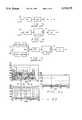
- FIG. 1is a block diagram of a system of the present invention for generating, transmitting, receiving, and processing a virtual noise waveform
- FIG. 2is block diagram of the waveform generator, transmitter, receiver, and signal processor of the system
- FIGS. 3-5are block diagrams representing current types of feature detectors used to sense the presence of a radar waveform and identify the source of the waveform wherein FIG. 3 is a block diagram for a n th law detector for detecting radar carrier frequencies, FIG. 4 is a delay detector for detecting chip rate of a radar signal, and FIG. 5 is a split band detector for sensing the hop rate of a radar signal;
- FIG. 6Arepresents a detected radar waveform
- FIG. 6Bthe output of a square law detector to which the detected waveform is applied;
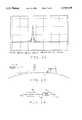
- FIG. 7represents a frequency spectrum and illustrates spectrum hopping of a transmitted radar waveform
- FIG. 8is a representative graph illustrating the detection range of electronic intelligence (ELINT) detectors as a function of the effective radiated power of a radar system
- FIG. 9is a block diagram of a Nyquist waveform generator for producing a desired waveform depending upon the target information being sought and a received radar return signal processing;
- FIG. 10is a representation of a Nyquist pulse waveform as a function of time
- FIG. 11is a similar representation of the waveform as a function of frequency
- FIG. 12represents a radar ranging signal indicating range to a target
- FIG. 13illustrates an airborne radar system used to collect intelligence
- FIG. 14illustrates operation of a waveform suppression means of the apparatus for producing a radar signal having no discernible attributes
- FIG. 15represents a virtual noise waveform of the present invention when processed by a square law detector
- FIG. 16Aillustrates the suppression of a waveform feature by a filter of the suppression means
- FIG. 16Billustrates the resultant transmitted, featureless waveform
- FIG. 17is a block diagram of the waveform generation means.
- Corresponding reference charactersindicate corresponding parts throughout the drawings.
- a radar platformcomprises an aircraft A in which a radar system R is installed. It will be understood, however, that the invention, as described hereinafter, may be used with any radar platform.
- To obtain information about a target T of interestrequires that the airplane be flown some distance relative to the object and that the radar system generate and transmit a radar signal S generally in the direction of the target.
- the radar signalhas a number of characteristics. These include the strength of the signal (transmitted power), frequency, coding, etc.
- a return signal Uis reflected back toward the airplane.
- the return signalis received, it is processed by the radar system to produce desired intelligence information about the target.
- a ranging signalis shown which is typical of the type of information to be obtained by a radar system.
- the radar signal from the airplaneis detectable by a surveillance system E.
- the surveillance systemdoes not necessarily know of the presence of radar R, but rather scans known radar frequency bandwidths.
- the surveillance systemmay obtain a detected waveform W such as shown in FIG. 6A.
- the surveillanceincludes a variety of feature detectors whose function are to analyze the waveform and determine whether or not any discernible features are present by which the waveform W could be determined to have been transmitted by a particular radar system. Knowing the characteristics of a radar system essentially identifies the source of the radar signal.
- three different types of feature detectorsare respectively designated F1-F3. Detector F1 in FIG.
- n law detectorsuch as a square law type detector; although, quad law and hex law detectors are also used.
- the sensed waveformis applied to a bandpass filter BPF, and then to a square law detector module NLM.
- the output of the detector moduleis displayed by a spectrum analyzer SA.
- the output displayed by the spectrum analyzeris a waveform pattern such as shown in FIG. 6B.
- the waveform Wis shown to have a series of readily identifiable peaks P1..Pn. Because of the occurrence of these peaks, it is first clear that the waveform W is not merely comprised of randomly occurring noise. Secondly, by ascertaining the respective frequencies at which the peaks occur, it is possible to particularly identify the source of the signal.
- n law detector F 1a chip rate or bit coding detector F2 is used.
- the filtered waveformis split into two paths.
- the waveformis then recombined at a junction point JP with the waveform on one of the paths having first been passed through a time delay TD.
- the resulting waveformis displayed by a spectrum analyzer SA.
- the third feature detector F3is used for determining hop rate of a detected waveform or the rate at which the radar waveform is shifted from one carrier frequency to another.
- the third feature detector F3is used for determining hop rate of a detected waveform or the rate at which the radar waveform is shifted from one carrier frequency to another.
- the third feature detector F3is used for determining hop rate of a detected waveform or the rate at which the radar waveform is shifted from one carrier frequency to another.
- the third feature detector F3is used for determining hop rate of a detected waveform or the rate at which the radar waveform is shifted from one carrier frequency to another.
- BPF2 and NLM2are additively combined with the result being passed through a third bandpass filter BPF3.
- the waveformis again split in two and routed over separate paths.
- the segmentsare recombined at a junction point JP with one of the segments having again first been passed through a time delay TD. Again, the results are displayed on a spectrum analyzer SA.
- FIG. 8is a graph depicting the relative detection range for an electronic intelligence (ELINT) detector E. While FIG. 8 is representative for one band of radar frequencies, it will be understood that a similar graph could be presented for other radar frequency bands as well.
- ELINTelectronic intelligence
- the abscissa of the graphis detection range, the ordinate effective radiated power (ERP) for a radar system R. Further, four different power levels (the sloping lines) are represented with each line representing a different sensor sensitivity level. The top line is for the most sensitive sensor level, and the lowest line, the least sensitive sensor level. What this indicates is that for the given capabilities of an ELINT detector, the lower the effective radiated power of a radar system, the closer the platform can get to the detector before the detector is capable of determining the presence of the radar. Regardless, use of the feature detectors described above still enables detection and analysis of a conventional radar waveform to be achieved.
- Apparatus 10 of the present inventionis shown in FIG. 1.
- the apparatusis for use in a radar system for generating a radar waveform which has no discernible attributes. What this means is that if the waveform of FIG. 6A is processed by the feature detectors F1-F3, the result would be a signal indistinguishable from the noise portion of the FIG. 6B waveform. However, the received, return waveform resulting from the transmitted waveform energy striking the target and being reflected back to the apparatus would have sufficiently recognizable features so the apparatus could process the return signal and obtain useful target information.
- Apparatus 10includes a carrier means 12 for generating a carrier wave having a frequency C within a predetermined band of frequencies. As is well known in the art, there are different bands of radar frequencies. Means 12 may be capable of generating the carrier frequency in any preferred frequency band. For this purpose, means 12, which is a coherent exciter, includes a stable frequency reference 14 for a given frequency band. The output of this reference is supplied to a synthesizer 16 for matching the frequency reference with other portions of the apparatus.
- Means 18includes a generator 20 for generating a series of pulses in a pseudo-random pattern.
- the generatorgenerates digital pulses at very high code rate, this rate being at least four (4) times higher than that necessary for the information bandwidth required of the transmitted waveform. A repetition rate on the order of 8-10 times faster than that at which a noise generator would normally produce such pulses is readily achievable.
- the generatoris operated to generate pulses in accordance with a predetermined coding scheme. The scheme employed may be variable in accordance with the type of target interrogation being performed by the apparatus.
- the output from the pseudo-noise generatoris applied to a pulse or waveform generator 22. This generator takes the digital pulse output of generator 20 and converts it into a waveform of an intermediate frequency (IF). Waveform generator 22 is supplied two inputs from coherent exciter 16.
- IFintermediate frequency
- generator 20 of waveform generation means 18generates two independent antipodal ( ⁇ ) psuedo-random impulse sequences. These are represented by an in-phase psuedo random noise generator 20i, and a quadrature phase psuedo random noise generator 20q. These generators respectively generate in-phase (i) and quadrature phase (q) code message sequences which are supplied to waveform generator 22.
- Generator 22includes two finite impulse response (FIR) filters 23i and 23q to which the i and q sequences are respectively supplied. The filters act as pulse shaping networks for the psuedo random impulse sequences.
- FIRfinite impulse response
- the filtered output from filter 23qis applied to a delay module 23d where the filtered quadrature sequence is filtered by a factor (T 0 /2) where T 0 is the axis chip length and is inversely proportional to the FIR filter bandwidth.
- the resulting i and q sequencesare supplied to a quadrature modulator 23m for upconversion to a suitable offset frequency for subsequent use by baseband upconverter 24.
- Waveform generator means 18is supplied timing and control inputs from coherent exciter 12. One input is a systems reference input, the other a direct digital synthesizer (DDS) clock input. This latter input is used to synchronize operation of the coherent exciter 12 psuedo-random generator 18, and waveform generator 22.
- DDSdirect digital synthesizer
- the output of the generatorappears as a random noise signal.
- any waveform attributes which might still be discernible by a feature detectorare subsequently suppressed in accordance with the further waveform processing as described hereinafter.
- the operation of the waveform generatoris a function of the desired information being sought. For example, in FIG. 12, a waveform is shown which may be used to obtain ranging information.
- the output waveform of generator 22 and the carrier waveform from exciter 16are supplied to an upconverter 24.
- the carrier waveformis supplied to the upconverter through a three way power divider 25.
- the carrier waveformis modulated with the waveform produced by generator 22 in an image reject mixer 26.
- the output waveform of coherent exciter 12 or waveform generator 18may be shifted in frequency (hopped) at different times. This frequency hopping is shown in FIG. 7. It will further be understood that while the frequency hopping pattern shown in this drawing presents a stairstep pattern, in actuality, the hopping pattern is a random one.
- the sequence H1, H2, H3, . . . Hn-1, Hn of carrier frequencies shown in FIG. 7the actual sequence may be H1, H3, Hn-1, H2, Hn, etc.
- the modulated waveform for the portion of signal at one frequency, frequency H1, for exampleis shown.
- suppression means 28first includes a filter 30.
- the modulated waveform indicated Wm in FIG. 14represents the output from upconverter 24. This waveform is supplied to the input of filter 30 which selectively filters the waveform.
- the resulting waveform, Wf in FIG. 14,has a bandwidth which, for example, is only one-tenth that of the input waveform.
- the feature of the input waveformis located in a null portion of the filter. That is, the feature portion of the waveform passed by the filter is on the order of 20db-30 db below the peak level of the waveform.
- FIGS. 16A and 16BThis greatly reduces the energy of the transmitted feature making it harder to detect the waveform.
- This feature suppressionis further shown in FIGS. 16A and 16B.
- FIG. 16Athe waveform Wm is superimposed on the filter characteristics.
- the feature location(pulse peak shown in FIG. 12) now occurs at a null in the filter.
- the resultant waveform from the filteris shown in FIG. 16B with the peak location feature now suppressed so as to not be discernible.
- the waveform Wfis applied to a programmable attenuator 32.
- Attenuator 32further serves to reduce any remaining power peaks in the waveform that might lead to detection of the transmitted waveform by a detector.
- the amount of attenuationis controlled, as described hereinafter, so that even though the transmitted waveform is now a low energy or virtual noise waveform having no attributes discernible by a feature detector, the waveform still has sufficient energy that a received return waveform from the target can be processed to yield desired information about the target.
- the output from attenuator 32is a waveform Wa. This waveform is now supplied to through a linear amplifier 34 to a propagation means 36.
- Propagation means 36transmits the waveform Wa and receives a return waveform which is processed to obtain the desired information.
- the virtual noise waveform transmitted by the antennais a low power waveform as a result of the filtering by filter 30 and further suppression by attenuator 32.
- the resultis that the transmitted waveform is as shown in FIG. 15.
- the waveformwhich is shown as a waveform resulting from processing by a square law detector F1
- the peaks P which are prevalent in the processed waveform of FIG. 6Bare not present because they are not there to be detected in the first place.
- the other feature analyzers previously discussedwould similarly produce no results enabling an investigator to determine that a radar illumination is taking place.
- Apparatus 10further includes means 44 for initially processing the received return waveform to obtain pertinent information about a target at which the transmitted waveform is directed.
- the output of receiver means 44is provided to a processor 100 (see FIG. 9) where an autocorrelation is performed with the return waveform to obtain target information.
- the return signalis divided into separate processing channels, a ⁇ channel for energy, and a boresight channel ⁇ .
- the duplexer outputsare respectively applied to the inputs of a low noise amplification module 46 having two separate and identical channels.
- Each channelincludes a limiter 48 through which the respective signals are supplied to a programmable attenuator 50. The output from each attenuator is then supplied to a linear noise amplifier 52.
- each channel outputis supplied as an input to a programmable RF attenuator module 54 comprising separate programmable attenuators 56. Both the attenuators 56 and attenuator 32 have gain control inputs for adjusting the resulting signal level of the return waveform so it is sufficient for processing.
- a power management controller 58provides an output to both attenuator 32 of suppression means 28, and to an automatic gain controller 60. Controller 60 controls the attenuation level of both of the programmable attenuators 50 and 56.
- the ⁇ and ⁇ channel signalsare applied to an IF downconverter 62.
- the carrier frequency of coherent exciter 16is supplied through three-way power divider 25 to the downconverter.
- Each separate channel inputis first applied to a power divider, the Y, channel to a power divider 64, and the ⁇ channel to a power divider 66.
- These channelsare further divided into two separate sub-channels, the sub-channels are supplying inputs to separate mixers.
- the two sub-channels for the ⁇ channelare applied to respective mixers 68, 70, and those for the ⁇ channel to mixers 72, 74.
- Each output from each of these power dividersis an in-phase output.
- One output from power divider 25is supplied to a power divider 76 where the carrier frequency is divided into in-phase and quadrature phase components.
- the in-phase output from power divider 76is supplied to mixer 68, the quadrature phase component to mixer 70.
- a second output from power divider 25is supplied to a power divider 78.
- This power dividersimilarly has in-phase and quadrature phase components, these being respectively supplied to mixers 72 and 74. After domconversion, the two in-phase and two quadrature phase signals are supplied to respective preamplifiers, 80a-80d.
- the in-phase and quadrature signalsare supplied to a programmable RF attenuator module 82 comprising respective programmable attenuators 82a-82d. Each of these attenuators is supplied a control input from gain controller 60. The output from each attenuator 82 is supplied to one filter 86a-86d of a waveform filter module 86. After filtering, the respective waveforms are applied to analog-to-digital (A/D) converters 88a-88d of a digitizer module 88. The converters are supplied a clock signal from coherent exciter 16. Each converter produces an 8-bit digital output, for example, which is used for further signal processing by processor 100 for mapping a target area for obtaining other target information.
- A/Danalog-to-digital
- apparatus 10is based upon a Nyquist signal model.
- a sequence of pseudo randomly generated digital pulses from generator 18are supplied to Nyquist filter 30 of suppression means 28.
- the generator 18 outputmay also be sent to a Fast Fourier Transform (FFT) 102 of signal processor 100, or the output of the filter 30 may be routed to this FFT.
- FFTFast Fourier Transform
- the transmitted waveformilluminates target T and the return waveform is directed to processor 100 through a receiver electronics 46, 62, 82.
- the resulting signalis then applied to a Fast Fourier Transform 104.
- the output of FFT 102is convened to its complex conjugate at 106.
- the output of 106 and FFT 104are recombined at 108.
- processor 100is performing an autocorrelation on the return waveforms.
- the resulting waveformis now supplied to another FFT 110 for further waveform processing.
- the waveformwhich now resembles that shown in FIG. 12, is passed through a magnitude detector 112 which monitors and controls the waveform peak of the final waveform.
- the waveformis a virtual noise waveform having no discernible attributes so the waveform appears as a random occurrence and does not reveal either its presence or any information about the source of the waveform to a waveform analyzer or interrogator.
- the apparatus and method of the inventionfacilitates covert radar operations by preventing long range detection and ready identification of a radar waveform by an enemy.
- the waveform generated by the apparatus and method of the inventionis a low peak power waveform which is generated using pseudo-random noise generation techniques. Other techniques employed in generating the waveform may include coherent integration, coherent frequency hopping, and continuous phase.
- the virtual-noise waveformmodulates a carrier wave, and the resulting signal is filtered and attenuated by approximately 30 db so the resulting waveform appears only in a narrow portion of a broad frequency spectrum and any characteristic features of the waveform are greatly suppressed. Suppression of the features of the finally transmitted waveform are such that it has no discernible attributes by which it can be identified as to a source of origin.
- the apparatus and methodprovide for a received, return signal to be readily detected and processed so as to provide desired information about the target at which the transmitted waveform was directed. Use of the apparatus and method to produces an undetectable radar signal usable in a wide variety of radar applications which are similar to those for which conventional radar signals are used. This is done without any degradation in the performance of a radar system, and the apparatus and method of the invention can be implemented with existing radar systems.
Landscapes
- Engineering & Computer Science (AREA)
- Radar, Positioning & Navigation (AREA)
- Remote Sensing (AREA)
- Computer Networks & Wireless Communication (AREA)
- Physics & Mathematics (AREA)
- General Physics & Mathematics (AREA)
- Radar Systems Or Details Thereof (AREA)
Abstract
Description
Claims (32)
Priority Applications (5)
| Application Number | Priority Date | Filing Date | Title |
|---|---|---|---|
| US08/656,863US5719579A (en) | 1996-05-30 | 1996-05-30 | Virtual noise radar waveform for reduced radar detectability |
| CA002255890ACA2255890C (en) | 1996-05-30 | 1997-05-30 | Virtual noise radar waveform for reduced radar detectability |
| PCT/US1997/009253WO1997045752A1 (en) | 1996-05-30 | 1997-05-30 | Virtual noise radar waveform for reduced radar detectability |
| GB9824965AGB2330029B (en) | 1996-05-30 | 1997-05-30 | Virtual noise radar waveform for reduced radar detectability |
| US09/024,003US5861834A (en) | 1996-05-30 | 1998-02-14 | Virtual noise radar waveform for reduced radar detectability |
Applications Claiming Priority (1)
| Application Number | Priority Date | Filing Date | Title |
|---|---|---|---|
| US08/656,863US5719579A (en) | 1996-05-30 | 1996-05-30 | Virtual noise radar waveform for reduced radar detectability |
Related Child Applications (1)
| Application Number | Title | Priority Date | Filing Date |
|---|---|---|---|
| US09/024,003Continuation-In-PartUS5861834A (en) | 1996-05-30 | 1998-02-14 | Virtual noise radar waveform for reduced radar detectability |
Publications (1)
| Publication Number | Publication Date |
|---|---|
| US5719579Atrue US5719579A (en) | 1998-02-17 |
Family
ID=24634900
Family Applications (2)
| Application Number | Title | Priority Date | Filing Date |
|---|---|---|---|
| US08/656,863Expired - LifetimeUS5719579A (en) | 1996-05-30 | 1996-05-30 | Virtual noise radar waveform for reduced radar detectability |
| US09/024,003Expired - LifetimeUS5861834A (en) | 1996-05-30 | 1998-02-14 | Virtual noise radar waveform for reduced radar detectability |
Family Applications After (1)
| Application Number | Title | Priority Date | Filing Date |
|---|---|---|---|
| US09/024,003Expired - LifetimeUS5861834A (en) | 1996-05-30 | 1998-02-14 | Virtual noise radar waveform for reduced radar detectability |
Country Status (4)
| Country | Link |
|---|---|
| US (2) | US5719579A (en) |
| CA (1) | CA2255890C (en) |
| GB (1) | GB2330029B (en) |
| WO (1) | WO1997045752A1 (en) |
Cited By (27)
| Publication number | Priority date | Publication date | Assignee | Title |
|---|---|---|---|---|
| US5861834A (en)* | 1996-05-30 | 1999-01-19 | Esco Electronics Corporation | Virtual noise radar waveform for reduced radar detectability |
| US6081226A (en)* | 1998-07-10 | 2000-06-27 | Northrop Grumman Corporation | Multi-mode radar exciter |
| US6430170B1 (en)* | 1999-05-27 | 2002-08-06 | Qualcomm Inc. | Method and apparatus for generating random numbers from a communication signal |
| US6720920B2 (en) | 1997-10-22 | 2004-04-13 | Intelligent Technologies International Inc. | Method and arrangement for communicating between vehicles |
| US20050200516A1 (en)* | 2004-01-26 | 2005-09-15 | Physical Domains | Retrodirective noise-correlating (RNC) radar methods and apparatus |
| US20050267716A1 (en)* | 2004-05-25 | 2005-12-01 | Texas Instruments Incorporated | System and method for generating and measuring noise parameters |
| US20050275583A1 (en)* | 2004-06-14 | 2005-12-15 | Satoshi Mikami | Radar equipment |
| US20070097785A1 (en)* | 2004-11-03 | 2007-05-03 | Larry Kremer | Suppressed feature waveform for modulated sonar transmission |
| US20080140318A1 (en)* | 1997-10-22 | 2008-06-12 | Intelligent Technologies International, Inc. | Weather Monitoring Techniques |
| US20090073025A1 (en)* | 2007-09-13 | 2009-03-19 | Matsushita Electric Industrial Co., Ltd. | Radar apparatus, method for controlling the same, and vehicle including the same |
| US20100245156A1 (en)* | 2007-10-19 | 2010-09-30 | Nireco Corporation | Distance measuring apparatus and distance measuring method |
| US20120209113A1 (en)* | 2010-07-19 | 2012-08-16 | Pat Sankar | Pulse compression system and method |
| US8369967B2 (en) | 1999-02-01 | 2013-02-05 | Hoffberg Steven M | Alarm system controller and a method for controlling an alarm system |
| US20130181862A1 (en)* | 2010-07-12 | 2013-07-18 | Nireco Corporation | Distance measuring apparatus and distance measuring method |
| US20130325323A1 (en) | 1998-10-22 | 2013-12-05 | American Vehicular Sciences | Vehicle software upgrade techniques |
| US8747321B2 (en) | 2012-08-15 | 2014-06-10 | Scidea Research, Inc. | Structured random permutation pulse compression systems and methods |
| US8892495B2 (en) | 1991-12-23 | 2014-11-18 | Blanding Hovenweep, Llc | Adaptive pattern recognition based controller apparatus and method and human-interface therefore |
| US8974390B1 (en) | 2013-10-03 | 2015-03-10 | Scidea Research, Inc. | Pulse compression systems and methods |
| WO2015084549A1 (en)* | 2013-12-06 | 2015-06-11 | Honeywell International Inc. | Adaptive radar system with multiple waveforms |
| US20150234036A1 (en)* | 2012-09-19 | 2015-08-20 | Furuno Electric Co., Ltd. | Pulse compression radar |
| US20150247920A1 (en)* | 2012-09-19 | 2015-09-03 | Furuno Electric Co., Ltd. | Pulse Compression Radar |
| US9443358B2 (en) | 1995-06-07 | 2016-09-13 | Automotive Vehicular Sciences LLC | Vehicle software upgrade techniques |
| EP3077842A4 (en)* | 2013-12-06 | 2017-07-26 | Honeywell International Inc. | Receiver with programmable gain for uwb radar |
| US10070825B2 (en) | 2013-11-26 | 2018-09-11 | Scidea Research, Inc. | Pulse compression systems and methods |
| US10361802B1 (en) | 1999-02-01 | 2019-07-23 | Blanding Hovenweep, Llc | Adaptive pattern recognition based control system and method |
| CN111830469A (en)* | 2020-06-02 | 2020-10-27 | 中汽数据有限公司 | A classification, identification and filtering method for noise data of vehicle-mounted millimeter-wave radar |
| US11175394B2 (en) | 2019-03-27 | 2021-11-16 | Raytheon Company | Binary to quad phase generator |
Families Citing this family (20)
| Publication number | Priority date | Publication date | Assignee | Title |
|---|---|---|---|---|
| US6362737B1 (en)* | 1998-06-02 | 2002-03-26 | Rf Code, Inc. | Object Identification system with adaptive transceivers and methods of operation |
| RU2193214C1 (en)* | 2001-05-15 | 2002-11-20 | Даль Виктор Сергеевич | Signal generator of noise interference |
| RU2186407C1 (en)* | 2001-05-31 | 2002-07-27 | Военно-морской институт радиоэлектроники | Generator of signals of impulse noise |
| US7020095B2 (en)* | 2001-06-16 | 2006-03-28 | Maxim Integrated Products, Inc. | System and method for modulation of non-data bearing carriers in a multi-carrier modulation system |
| JP2005265615A (en)* | 2004-03-18 | 2005-09-29 | Optex Co Ltd | Microwave sensor |
| JP2005283384A (en)* | 2004-03-30 | 2005-10-13 | Optex Co Ltd | Microwave sensor and system for preventing mutual interference of microwave sensor |
| ATE491963T1 (en)* | 2005-05-31 | 2011-01-15 | Saab Ab | STEP FREQUENCY RADAR DEVICE |
| CN1968029A (en)* | 2005-11-16 | 2007-05-23 | 弥亚微电子(上海)有限公司 | Spread-spectrum modulation and demodulation method by special spread spectrum sequence and device |
| RU2342676C1 (en)* | 2007-03-05 | 2008-12-27 | Государственное образовательное учреждение высшего профессионального образования Воронежское высшее военное авиационное инженерное училище (военный институт) | Filter of rectangular video pulse |
| DE102010012624A1 (en)* | 2010-03-24 | 2011-09-29 | Valeo Schalter Und Sensoren Gmbh | Driver assistance device for a vehicle and method for operating a radar device |
| RU2443058C2 (en)* | 2010-04-05 | 2012-02-20 | Федеральное Государственное Унитарное Предприятие "Научно-Исследовательский Институт "Экран" | Method for coherent interference formation |
| JP5842143B2 (en) | 2010-09-02 | 2016-01-13 | パナソニックIpマネジメント株式会社 | Radar equipment |
| US9372259B2 (en)* | 2011-08-12 | 2016-06-21 | Panasonic Corporation | Radar apparatus |
| US10261179B2 (en)* | 2016-04-07 | 2019-04-16 | Uhnder, Inc. | Software defined automotive radar |
| US10698099B2 (en)* | 2017-10-18 | 2020-06-30 | Leolabs, Inc. | Randomized phase and amplitude radar codes for space object tracking |
| US10921423B2 (en) | 2018-07-25 | 2021-02-16 | United States Of America As Represented By The Secretary Of The Navy | Multicarrier and frequency hopped radar waveform generator using efficient digital synthesis |
| WO2020183392A1 (en) | 2019-03-12 | 2020-09-17 | Uhnder, Inc. | Method and apparatus for mitigation of low frequency noise in radar systems |
| EP3819660B1 (en)* | 2019-11-05 | 2025-01-08 | NXP USA, Inc. | Radar transmitter module for digital modulation |
| US11953615B2 (en) | 2020-01-13 | 2024-04-09 | Uhnder Inc. | Method and system for antenna array calibration for cross-coupling and gain/phase variations in radar systems |
| EP4254002B1 (en)* | 2022-03-29 | 2025-04-30 | GM Cruise Holdings LLC | Low phase noise radar system |
Citations (4)
| Publication number | Priority date | Publication date | Assignee | Title |
|---|---|---|---|---|
| US4706093A (en)* | 1984-03-26 | 1987-11-10 | Motorola, Inc. | Monopulse tracking system substantially free of externally generated noise |
| US5053772A (en)* | 1990-09-04 | 1991-10-01 | Electronics & Space Corporation | Radar system employing a method for motion and range closure compensation |
| US5055850A (en)* | 1990-09-04 | 1991-10-08 | Electronics & Space Corporation | Waveform generator |
| US5075863A (en)* | 1988-02-09 | 1991-12-24 | Nkk Corporation | Distance measuring method and apparatus therefor |
Family Cites Families (1)
| Publication number | Priority date | Publication date | Assignee | Title |
|---|---|---|---|---|
| US5719579A (en)* | 1996-05-30 | 1998-02-17 | Esco Electronics Corporation | Virtual noise radar waveform for reduced radar detectability |
- 1996
- 1996-05-30USUS08/656,863patent/US5719579A/ennot_activeExpired - Lifetime
- 1997
- 1997-05-30CACA002255890Apatent/CA2255890C/ennot_activeExpired - Lifetime
- 1997-05-30WOPCT/US1997/009253patent/WO1997045752A1/enactiveSearch and Examination
- 1997-05-30GBGB9824965Apatent/GB2330029B/ennot_activeExpired - Lifetime
- 1998
- 1998-02-14USUS09/024,003patent/US5861834A/ennot_activeExpired - Lifetime
Patent Citations (4)
| Publication number | Priority date | Publication date | Assignee | Title |
|---|---|---|---|---|
| US4706093A (en)* | 1984-03-26 | 1987-11-10 | Motorola, Inc. | Monopulse tracking system substantially free of externally generated noise |
| US5075863A (en)* | 1988-02-09 | 1991-12-24 | Nkk Corporation | Distance measuring method and apparatus therefor |
| US5053772A (en)* | 1990-09-04 | 1991-10-01 | Electronics & Space Corporation | Radar system employing a method for motion and range closure compensation |
| US5055850A (en)* | 1990-09-04 | 1991-10-08 | Electronics & Space Corporation | Waveform generator |
Cited By (41)
| Publication number | Priority date | Publication date | Assignee | Title |
|---|---|---|---|---|
| US8892495B2 (en) | 1991-12-23 | 2014-11-18 | Blanding Hovenweep, Llc | Adaptive pattern recognition based controller apparatus and method and human-interface therefore |
| US9443358B2 (en) | 1995-06-07 | 2016-09-13 | Automotive Vehicular Sciences LLC | Vehicle software upgrade techniques |
| US5861834A (en)* | 1996-05-30 | 1999-01-19 | Esco Electronics Corporation | Virtual noise radar waveform for reduced radar detectability |
| US6720920B2 (en) | 1997-10-22 | 2004-04-13 | Intelligent Technologies International Inc. | Method and arrangement for communicating between vehicles |
| US20080140318A1 (en)* | 1997-10-22 | 2008-06-12 | Intelligent Technologies International, Inc. | Weather Monitoring Techniques |
| US8060308B2 (en) | 1997-10-22 | 2011-11-15 | Intelligent Technologies International, Inc. | Weather monitoring techniques |
| US6081226A (en)* | 1998-07-10 | 2000-06-27 | Northrop Grumman Corporation | Multi-mode radar exciter |
| US20130325323A1 (en) | 1998-10-22 | 2013-12-05 | American Vehicular Sciences | Vehicle software upgrade techniques |
| US10240935B2 (en) | 1998-10-22 | 2019-03-26 | American Vehicular Sciences Llc | Vehicle software upgrade techniques |
| US9535563B2 (en) | 1999-02-01 | 2017-01-03 | Blanding Hovenweep, Llc | Internet appliance system and method |
| US8369967B2 (en) | 1999-02-01 | 2013-02-05 | Hoffberg Steven M | Alarm system controller and a method for controlling an alarm system |
| US10361802B1 (en) | 1999-02-01 | 2019-07-23 | Blanding Hovenweep, Llc | Adaptive pattern recognition based control system and method |
| US6430170B1 (en)* | 1999-05-27 | 2002-08-06 | Qualcomm Inc. | Method and apparatus for generating random numbers from a communication signal |
| US20050200516A1 (en)* | 2004-01-26 | 2005-09-15 | Physical Domains | Retrodirective noise-correlating (RNC) radar methods and apparatus |
| US7177772B2 (en)* | 2004-05-25 | 2007-02-13 | Texas Instruments Incorporated | System and method for generating and measuring noise parameters |
| US20050267716A1 (en)* | 2004-05-25 | 2005-12-01 | Texas Instruments Incorporated | System and method for generating and measuring noise parameters |
| US20050275583A1 (en)* | 2004-06-14 | 2005-12-15 | Satoshi Mikami | Radar equipment |
| US7199751B2 (en)* | 2004-06-14 | 2007-04-03 | Fujitsu Limited | Radar equipment |
| US7596054B2 (en) | 2004-11-03 | 2009-09-29 | Drs Sustainment Systems, Inc. | Suppressed feature waveform for modulated sonar transmission |
| US20070097785A1 (en)* | 2004-11-03 | 2007-05-03 | Larry Kremer | Suppressed feature waveform for modulated sonar transmission |
| US7817081B2 (en)* | 2007-09-13 | 2010-10-19 | Panasonic Corporation | Radar apparatus, method for controlling the same, and vehicle including the same |
| US20090073025A1 (en)* | 2007-09-13 | 2009-03-19 | Matsushita Electric Industrial Co., Ltd. | Radar apparatus, method for controlling the same, and vehicle including the same |
| US7864105B2 (en)* | 2007-10-19 | 2011-01-04 | Nireco Corporation | Distance measuring apparatus and distance measuring method |
| US20100245156A1 (en)* | 2007-10-19 | 2010-09-30 | Nireco Corporation | Distance measuring apparatus and distance measuring method |
| US20130181862A1 (en)* | 2010-07-12 | 2013-07-18 | Nireco Corporation | Distance measuring apparatus and distance measuring method |
| US8665139B2 (en)* | 2010-07-12 | 2014-03-04 | Nireco Corporation | Distance measuring apparatus and distance measuring method |
| US8581778B2 (en)* | 2010-07-19 | 2013-11-12 | Scidea Research, Inc. | Pulse compression system and method |
| US20120209113A1 (en)* | 2010-07-19 | 2012-08-16 | Pat Sankar | Pulse compression system and method |
| US8747321B2 (en) | 2012-08-15 | 2014-06-10 | Scidea Research, Inc. | Structured random permutation pulse compression systems and methods |
| US20150247920A1 (en)* | 2012-09-19 | 2015-09-03 | Furuno Electric Co., Ltd. | Pulse Compression Radar |
| US20150234036A1 (en)* | 2012-09-19 | 2015-08-20 | Furuno Electric Co., Ltd. | Pulse compression radar |
| US9784819B2 (en)* | 2012-09-19 | 2017-10-10 | Furuno Electric Co., Ltd. | Pulse compression radar |
| US9791548B2 (en)* | 2012-09-19 | 2017-10-17 | Furuno Electric Co., Ltd. | Pulse compression radar |
| US9277901B2 (en) | 2013-10-03 | 2016-03-08 | Scidea Research, Inc. | Pulse compression systems and methods |
| US8974390B1 (en) | 2013-10-03 | 2015-03-10 | Scidea Research, Inc. | Pulse compression systems and methods |
| US10070825B2 (en) | 2013-11-26 | 2018-09-11 | Scidea Research, Inc. | Pulse compression systems and methods |
| US9329073B2 (en) | 2013-12-06 | 2016-05-03 | Honeywell International Inc. | Adaptive radar system with mutliple waveforms |
| EP3077842A4 (en)* | 2013-12-06 | 2017-07-26 | Honeywell International Inc. | Receiver with programmable gain for uwb radar |
| WO2015084549A1 (en)* | 2013-12-06 | 2015-06-11 | Honeywell International Inc. | Adaptive radar system with multiple waveforms |
| US11175394B2 (en) | 2019-03-27 | 2021-11-16 | Raytheon Company | Binary to quad phase generator |
| CN111830469A (en)* | 2020-06-02 | 2020-10-27 | 中汽数据有限公司 | A classification, identification and filtering method for noise data of vehicle-mounted millimeter-wave radar |
Also Published As
| Publication number | Publication date |
|---|---|
| GB2330029A (en) | 1999-04-07 |
| GB9824965D0 (en) | 1999-01-06 |
| WO1997045752A1 (en) | 1997-12-04 |
| GB2330029B (en) | 2000-07-26 |
| CA2255890C (en) | 2003-11-04 |
| CA2255890A1 (en) | 1997-12-04 |
| US5861834A (en) | 1999-01-19 |
Similar Documents
| Publication | Publication Date | Title |
|---|---|---|
| US5719579A (en) | Virtual noise radar waveform for reduced radar detectability | |
| Blunt et al. | Principles and applications of random FM radar waveform design | |
| JP2990097B2 (en) | Continuous-wave wide-band precision ranging radar equipment. | |
| US5898401A (en) | Continuous wave radar altimeter | |
| US4219812A (en) | Range-gated pulse doppler radar system | |
| US6211812B1 (en) | Quiet radar method and apparatus | |
| US9075138B2 (en) | Efficient pulse Doppler radar with no blind ranges, range ambiguities, blind speeds, or Doppler ambiguities | |
| US7676205B2 (en) | Active receiver detection and ranging | |
| US5731782A (en) | Ranging systems | |
| US6184820B1 (en) | Coherent pulse radar system | |
| KR20180130900A (en) | Narrow-band radar device and operating method thereof | |
| US5239555A (en) | Frequency hopping signal interceptor | |
| AU626695B2 (en) | Pulse radar apparatus and pulse discrimination circuit suitable for incorporation in a pulse radar apparatus | |
| US5124710A (en) | Coherent pulse radar system and method for the detection of a target presenting flashes of very short duration | |
| US5436973A (en) | Pseudo-random signal synthesizer with smooth, flat power spectrum | |
| US5109231A (en) | Radar arrangement | |
| US7064703B2 (en) | Methods and apparatus for randomly modulating radar altimeters | |
| GB2199459A (en) | Pulse doppler radar | |
| US4169993A (en) | Intercept receiver for double-side-band, noise-like signals | |
| JP3573430B2 (en) | Radar equipment | |
| RU2719545C1 (en) | System of information transmitting | |
| US5061933A (en) | Short-range radar system | |
| JP3727765B2 (en) | Receiver | |
| KR102499402B1 (en) | Chirp noise generation device and method for compression pulse signal | |
| JP2933454B2 (en) | Radio altimeter |
Legal Events
| Date | Code | Title | Description |
|---|---|---|---|
| AS | Assignment | Owner name:HAZELTINE CORPORATION, NEW YORK Free format text:ASSIGNMENT OF ASSIGNORS INTEREST;ASSIGNOR:TORRE, FRANK M.;REEL/FRAME:008161/0308 Effective date:19960524 | |
| AS | Assignment | Owner name:ESCO ELECTRONICS CORPORATION, MISSOURI Free format text:ASSIGNMENT OF ASSIGNORS INTEREST;ASSIGNORS:SAUER, MARK F.;KREMER, LARRY R.;ZIEGLER, JOHN A.;AND OTHERS;REEL/FRAME:008174/0589 Effective date:19960925 | |
| STCF | Information on status: patent grant | Free format text:PATENTED CASE | |
| AS | Assignment | Owner name:SYSTEMS & ELECTRONICS, INC., MISSOURI Free format text:ASSIGNMENT OF ASSIGNORS INTEREST;ASSIGNOR:ESCO ELECTRONICS CORPORATION;REEL/FRAME:010263/0834 Effective date:19990916 | |
| AS | Assignment | Owner name:HAZELTINE CORPORATION, NEW YORK Free format text:ASSIGNMENT OF ASSIGNORS INTEREST;ASSIGNOR:ESCO ELCTRONICS CORPORATION;REEL/FRAME:010272/0825 Effective date:19990916 Owner name:SYSTEMS & ELECTRONICS INC., MISSOURI Free format text:ASSIGNMENT OF ASSIGNORS INTEREST;ASSIGNOR:ESCO ELECTRONICS CORPORATION;REEL/FRAME:010272/0822 Effective date:19990916 Owner name:SYSTEMS & ELECTRONICS INC., MISSOURI Free format text:ASSIGNMENT OF ASSIGNORS INTEREST;ASSIGNOR:ESCO ELCTRONICS CORPORATION;REEL/FRAME:010272/0825 Effective date:19990916 | |
| AS | Assignment | Owner name:BANK OF AMERICA, NATIONAL ASSOCIATION, AS AGENT, M Free format text:SECURITY AGREEMENT;ASSIGNOR:SYSTEMS & ELECTRONICS, INC.;REEL/FRAME:010395/0558 Effective date:19990930 | |
| FPAY | Fee payment | Year of fee payment:4 | |
| AS | Assignment | Owner name:BANK OF AMERICA, N.A., MISSOURI Free format text:RELEASE;ASSIGNOR:SYSTEMS & ELECTRONICS, INC.;REEL/FRAME:014007/0586 Effective date:20030423 | |
| AS | Assignment | Owner name:SYSTEMS & ELECTRONICS, INC., MISSOURI Free format text:TERMINATION OF SECURITY INTEREST;ASSIGNOR:BANK OF AMERICA, N.A., AS AGENT;REEL/FRAME:014709/0464 Effective date:20030423 | |
| FPAY | Fee payment | Year of fee payment:8 | |
| AS | Assignment | Owner name:WACHOVIA BANK, NATIONAL ASSOCIATION, NORTH CAROLIN Free format text:PATENT SECURITY AGREEMENT;ASSIGNOR:SYSTEMS & ELECTRONICS INC.;REEL/FRAME:017286/0794 Effective date:20060131 | |
| AS | Assignment | Owner name:WACHOVIA BANK, NATIONAL ASSOCIATION, NORTH CAROLIN Free format text:PATENT SECURITY AGREEMENT;ASSIGNOR:DRS SUSTAINMENT SYSTEMS, INC.;REEL/FRAME:019580/0555 Effective date:20060615 | |
| FPAY | Fee payment | Year of fee payment:12 | |
| AS | Assignment | Owner name:DRS SUSTAINMENT SYSTEMS, INC.,MISSOURI Free format text:RELEASE BY SECURED PARTY;ASSIGNOR:WELLS FARGO BANK, N.A.;REEL/FRAME:024576/0798 Effective date:20100607 |