US5719557A - Photoelectric smoke detector - Google Patents
Photoelectric smoke detectorDownload PDFInfo
- Publication number
- US5719557A US5719557AUS08/627,509US62750996AUS5719557AUS 5719557 AUS5719557 AUS 5719557AUS 62750996 AUS62750996 AUS 62750996AUS 5719557 AUS5719557 AUS 5719557A
- Authority
- US
- United States
- Prior art keywords
- smoke
- chamber
- detection chamber
- smoke detection
- arrangement
- Prior art date
- Legal status (The legal status is an assumption and is not a legal conclusion. Google has not performed a legal analysis and makes no representation as to the accuracy of the status listed.)
- Expired - Lifetime
Links
- 239000000779smokeSubstances0.000titleclaimsabstractdescription221
- 238000001514detection methodMethods0.000claimsabstractdescription147
- 239000002245particleSubstances0.000claimsabstractdescription31
- 239000000428dustSubstances0.000claimsdescription11
- 230000000694effectsEffects0.000claimsdescription3
- 230000035945sensitivityEffects0.000description12
- 230000036039immunityEffects0.000description8
- 238000000149argon plasma sinteringMethods0.000description3
- 241000238631HexapodaSpecies0.000description2
- 206010069201Smoke sensitivityDiseases0.000description2
- 239000003086colorantSubstances0.000description2
- 210000003027ear innerAnatomy0.000description2
- 238000004519manufacturing processMethods0.000description2
- 239000000463materialSubstances0.000description2
- 239000013618particulate matterSubstances0.000description2
- 229920003023plasticPolymers0.000description2
- 239000007787solidSubstances0.000description2
- XUIMIQQOPSSXEZ-UHFFFAOYSA-NSiliconChemical compound[Si]XUIMIQQOPSSXEZ-UHFFFAOYSA-N0.000description1
- 238000009825accumulationMethods0.000description1
- 229920000122acrylonitrile butadiene styrenePolymers0.000description1
- 230000003247decreasing effectEffects0.000description1
- 230000003287optical effectEffects0.000description1
- 238000012216screeningMethods0.000description1
- 229910052710siliconInorganic materials0.000description1
- 239000010703siliconSubstances0.000description1
- 238000001228spectrumMethods0.000description1
- 238000002211ultraviolet spectrumMethods0.000description1
Images

Classifications
- G—PHYSICS
- G08—SIGNALLING
- G08B—SIGNALLING OR CALLING SYSTEMS; ORDER TELEGRAPHS; ALARM SYSTEMS
- G08B17/00—Fire alarms; Alarms responsive to explosion
- G08B17/10—Actuation by presence of smoke or gases, e.g. automatic alarm devices for analysing flowing fluid materials by the use of optical means
- G08B17/103—Actuation by presence of smoke or gases, e.g. automatic alarm devices for analysing flowing fluid materials by the use of optical means using a light emitting and receiving device
- G08B17/107—Actuation by presence of smoke or gases, e.g. automatic alarm devices for analysing flowing fluid materials by the use of optical means using a light emitting and receiving device for detecting light-scattering due to smoke
- G—PHYSICS
- G08—SIGNALLING
- G08B—SIGNALLING OR CALLING SYSTEMS; ORDER TELEGRAPHS; ALARM SYSTEMS
- G08B17/00—Fire alarms; Alarms responsive to explosion
- G08B17/10—Actuation by presence of smoke or gases, e.g. automatic alarm devices for analysing flowing fluid materials by the use of optical means
- G08B17/11—Actuation by presence of smoke or gases, e.g. automatic alarm devices for analysing flowing fluid materials by the use of optical means using an ionisation chamber for detecting smoke or gas
- G08B17/113—Constructional details
Definitions
- the present inventionrelates to a light scattering type photoelectric smoke detector, more particularly, a light scattering photoelectric smoke detector having a surface mounted photodiode detector oriented to a photoemitting diode to provide for good sensitivity and radio frequency interference immunity.
- Smoke detectors based on light scattering by smoke particleshave been known for a number of years. Such detectors at present utilize solid state components including photoemitting diodes and photodiode detectors, the two devices being incorporated in a fixed mounted arrangement within a smoke sensing chamber.
- the smoke sensing chamberis generally designed to exclude most ambient light influences while providing openings to permit entry of the smoke particles into the sensing chamber.
- There have been many such designs developed and patentedwhich rely upon the walls of the smoke chamber having labyrinth designs to allow the passage of the smoke particles while excluding ambient light from the interior of the chamber. Examples of such designs are shown in U.S. Pat. Nos. 3,914,616, 4,168,438, 4,315,158, 4,672,217 and 4,851,819.
- the photoemitting diodes and photodiode detectorsare mounted in either the sides of the chamber or on the bottom of the chamber, most typically with a 60 degree scattering angle along a horizontal plane between the photoemitting diodes and photodiode detectors.
- the design of many of the prior art smoke detection chambersresults in a generally horizontal flow of the smoke particles through the chamber.
- the photoemitting diode and photodiode detectorshould be mounted in such a way that the intersection of the transmitted light from the photoemitting diode and the view of the photodiode detector falls within the horizontal path of the smoke particles.
- the horizontal flowmay be shifted from the intersection thereby affecting the sensitivity of the smoke detector.
- the use of the 60° scattering angleincreases the distance between the photodiode detector and photoemitting diode thereby affecting the sensitivity and increasing the potential for dust particle interference.
- many of the prior art mounting arrangementsgenerally require the use of leads between the photodiode detector and/or the photoemitting diode and the printed circuit board carrying the other electrical and electronic components utilized in the detection and alarm circuitry. The use of such leads increases the potential susceptibility of the alarm units to radio frequency interference (RFI) with exposure to the increased number of radio frequency (RF) transmitters throughout the RF spectrum presently in use.
- RFIDradio frequency interference
- Smokeis generally classified as black or grey.
- Grey smoke particlesare generally much easier to detect as they tend to scatter the light from the photoemitting diode very well.
- photoelectric smoke detectorsare reasonably effective at detecting grey smoke.
- Black smoke particlesdo not generally scatter the light as well and many designs of photoelectric smoke detectors have difficulty properly detecting the presence and level of black smoke. This is particularly the case with those detectors utilizing a 60° scattering angle as, at this angle, the grey smoke to black smoke sensitivity is only 4:1. In these detectors which are usually set to detect grey smoke at about 3% per foot obscuration, the level of black smoke required to indicate an alarm state would be 12% per foot obscuration or higher. Thus, there still exists a need to provide very sensitive smoke detection of both black and grey smoke particles with minimal radio frequency interference.
- the present inventionprovides for a photoelectric smoke detector comprising a case having mounted therein a circuit board and a smoke detection chamber.
- the smoke detection chamberhas side walls with openings provided therein for ingress and egress of smoke particles, a top and a bottom.
- a photoemitting diodeis mounted in a mounting arrangement in the side wall of the smoke detection chamber so that a light beam from the photoemitting diode is transmitted across the smoke detection chamber without directly impinging upon either the top or the bottom surfaces.
- the bottom of the smoke detection chamberhas an opening therein with a shielding arrangement thereabout open to the chamber, the opening and shielding arrangement being located between the centerline of the smoke detection chamber and the mounting arrangement in the side wall of the chamber.
- the circuit boardis mounted to overlie the bottom surface and includes a photodiode detector mounted directly thereon and positioned generally in the opening so that it views into the smoke detection chamber through the opening and through the shielding arrangement, the shielding arrangement shielding the photodiode detector from incident light which may be present in the smoke detector chamber while providing for a diverging field of view of the photodiode detector.
- the diverging field of view of the photodiode detectorintersects the light beam of the photoemitting diode to define a detection volume contained within the smoke detection chamber located close to the photoemitting diode and the photodiode detector and spaced from the surfaces of the smoke detection chamber to minimize the effect on the photodiode detector of light from the photoemitting diode which is reflected exterior to the detection volume.
- a smoke detection chamberfor use in a photoelectric smoke detector.
- the smoke detection chambercomprises a side wall band encircling a detection volume to the interior thereof, a top and a bottom spaced from the side wall band to provide for open region for ingress and egress of smoke particles to and from the detection volume.
- the smoke detection chamberfurther includes a mounting arrangement for a photoemitting diode located in the side wall band of the smoke detection chamber so that a light beam from such photoemitting diode may be transmitted across the smoke detection chamber without directly impinging upon either the top or the bottom.
- the bottom of the smoke detection chamberhas an opening therein with a shielding arrangement thereabout open to the chamber for mounting of a photodiode detector so that it may view the detection volume through the opening and through the shielding arrangement.
- the opening and shielding arrangementare located between the centerline of the smoke detection chamber and the mounting arrangement in the side wall of the chamber.
- the shielding arrangementis capable of shielding a photodiode detector from incident light which may be present in the smoke detector chamber while providing for a diverging field of view of such photodiode detector.
- the intersection of the centerlines of the mounting arrangement and the shielding arrangementdefine the detection volume contained within the smoke detection chamber located close to the mounting arrangement and the shielding arrangement and spaced from the surfaces of the smoke detection chamber to minimize the impingement of light reflected exterior to the detection volume on a photodiode detector contained within the shielding arrangement.
- a smoke detection chamberfor use in a photoelectric smoke detector.
- the smoke detection chambercomprises side walls with openings provided therein for ingress and egress of smoke particles, a top and a bottom.
- a mounting arrangement for a photoemitting diodeis located in the side wall of the smoke detection chamber so that a light beam from a photoemitting diode may be transmitted across the smoke detection chamber without directly impinging upon either the top or the bottom surfaces.
- the bottom of the smoke detection chamberhas an opening therein with a shielding arrangement thereabout open to the chamber for mounting of a photodiode detector so that it may view into the smoke detection chamber through the opening and through the shielding arrangement.
- the opening and shielding arrangementare located between the centerline of the smoke detection chamber and the mounting arrangement in the side wall of the chamber.
- the shielding arrangementis capable of shielding a photodiode detector from incident light which may be present in the smoke detector chamber while providing for a diverging field of view of such photodiode detector.
- the intersection of the centerlines of the mounting arrangement and the shielding arrangementdefine a detection volume contained within the smoke detection chamber located close to the mounting arrangement and the shielding arrangement and spaced from the surfaces of the smoke detection chamber to minimize the impingement of light reflected exterior to said detection volume on a photodiode detector contained within the shielding arrangement.
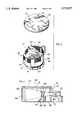
- FIG. 1is a side view in cross section of a preferred embodiment of the smoke detector according to the present invention
- FIG. 2is a illustration of the intersection of the fields of view of the photodiode detector and photoemitting diode
- FIG. 3is a exploded perspective view of the smoke chamber and printed circuit board of the smoke alarm of FIG. 1;
- FIG. 4is a side view in cross section of a second embodiment of a smoke detection chamber according to the present invention.
- FIG. 1A first preferred embodiment of the smoke detector of the present invention is illustrated in FIG. 1 generally indicated by the numeral 10.
- the smoke detector 10is a ceiling or wall mountable unit having a case 12 of extruded polymeric material.
- the casehas a base 14 to which is releasably attached a cover 16 having openings 18 to permit entry of smoke into the interior of the case 12. Openings 18 are provided with a fine mesh screen 20 to prevent entry of insects and other large particulate matter into the interior of the case 12.
- a printed circuit board 22Mounted within the case 12 in the base 14 is a printed circuit board 22.
- the printed circuit boardhas electronic components 24 which typically make up the smoke alarm circuitry mounted to one or both sides of the printed circuit board.
- electronic components 24are surface mounted components. The details of the alarm circuitry are not shown as the design of such circuitry is within the knowledge of ordinary workers in the art of smoke alarm design.
- Mounted on the printed circuit board 22is a photodiode detector 26 and a smoke detection chamber 30. The photodiode detector 26 is mounted such that the it views into the smoke detection chamber 30 as will be described further below.
- the first preferred embodiment of the smoke detection chamber 30 illustrated in FIGS. 1 and 3,is in the form of a cylinder preferably having an internal diameter between about 2 to 3 inches, however other shapes are possible.
- the smoke detection chamberhas side walls 32, a top 34 and a bottom 36.
- the bottom 36 of the chamber 30will in fact form the upper surface of the chamber, while the top 34 of the chamber 30 will form the lower surface.
- these partsare named in relation to their attachment to the circuit board 22.
- the smoke detection chamber 30may be molded in more than one piece depending upon the complexity of the structures contained therein.
- the side 32 and bottom 36may be molded in one piece and the top 34 may be molded as a separate piece which may be releasably attached to the other section of the smoke chamber 30.
- the smoke detection chamber 30is constructed of a dark colored plastic, usually a black plastic preferably having a matte or flat finish.
- a particularly preferred material for the smoke detection chamber 30is black ABS plastic.
- the sidewall 32 of smoke detection chamber 30is provided with openings 40 for ingress and egress of smoke particles into the smoke detection chamber 30.
- openings 40are preferably provided at the periphery of the sidewall 32 adjacent both the top 34 and bottom 36.
- the openings 40are clear in that they do not have any obstructions for the free flow of smoke particles such as labyrinths or the like and are provided with a fine mess screen 41 to reduce the entry of insects and large particulate matter into the smoke chamber 30 while allowing passage of smoke particles into the chamber.
- Smoke detection chamber 30 in the sidewall 32is also provided with a mounting arrangement 42 for a photoemitting diode 44.
- Mounting arrangement 42has extending walls 46 to provide a tunnel within which is mounted the photoemitting diode 44. Extending walls 46 preferably extend beyond the end of the photoemitting diode 44 to bound or limit the outer rays of the beam of light 48 emitted by the photoemitting diode 44 to provide for a relatively narrow beam of light broadcasting across the smoke chamber 30.
- the mounting arrangementpreferably restricts the light beam of the photoemitting diode 44 so that the beam only impinges upon the opposite sidewall 33 and not on either the top 34 or bottom 36.
- These extending walls 46also provide for shielding of the light beam 48 of the photoemitting diode 44 to reduce the possibility of stray light from the photoemitting diode 44 shining directly onto the photodiode detector 26.
- the smoke detection chamber 30is preferably provided with reticulated structures 38 in the sidewall 33 directly opposite the photoemitting diode 44 as well as on the top 34.
- These reticulated areas 38 of the smoke detection chamber 30reduce the possibility of reflection of light from the wall 33 and the top 34 and in addition provide an area where any dust which may enter the smoke detection chamber 30 may collect without causing scattering of light to reflect and impinge upon the photodiode detector 26.
- These dust hiding areasare located such that they are not both in the path of the light beam from the photoemitting diode and also within the view of a photodiode detector as described herein below. While these areas may in one or the other of these locations, they are not located so as to satisfy both conditions.
- the smoke detection chamber 30is preferably mounted directly on the printed circuit board 22 by means of mounting clips 50 inserted through openings provided in the printed circuit board 22.
- the bottom 36 of the smoke detection chamberis provided with an opening 52 having a shielding arrangement 54 to overlay the photodiode detector 26 mounted on the printed circuit board 22.
- the shielding arrangement 54is of a shape to reduce the possibility of incident light falling onto the photodiode detector 26.
- the shielding arrangement 54may be of any suitable shape, for example a right circular cylinder having openings in the top and right circular cylinder having openings in the top and bottom or a rectangular or square structure with an open top and bottom. In the embodiment illustrated in the figures, the shielding arrangement 54 is a square shaped structure having an open top and bottom.
- the wall 56 of the shielding arrangement closest to the position of the photoemitting diode 44is of a height to prevent any stray incident light from the photoemitting diode 44 from falling directly on the photodiode detector 26.
- This wall 56may be provided with a reticulated groove 59 for holding any dust particles which may come in contact with the shielding arrangement 54 and hiding such dust particles from the field of view of the photodiode detector 26.
- the opposite wall 58has a height or shape to prevent any incident light which may enter the chamber 30 through the openings 40 for ingress and egress of smoke particles from falling on the photodiode detector 26.
- Wall 58may also be provided with an inclined portion 60 to provide for increased shielding of the photodiode detector 26 from any incident light which may enter the smoke chamber 30.
- the photodiode detector 26 contained within the shielding arrangement 54has a field of view 62 which intersects the light beam 48 of the photoemitting diode 44 generally perpendicularly in a vertical plane to provide for the detection volume to be located within the smoke detection chamber 30 close to both the photoemitting diode 44 and photodiode detector 26 yet spaced from the surfaces of the smoke detection chamber 30 to minimize the effect on the photodiode detector 26 of light from the photoemitting diode 44 which is reflected exterior to the detection volume.
- the arrangement of the photoemitting diode 44 and photodiode detector 26 with a scattering angle at a generally right angle in the vertical planepermits the detection volume 64 to be located close to the photoemitting diode 44 where the intensity of the light beam from the photoemitting diode 44 is higher and close to the photodiode detector 26 where its sensitivity is higher thereby increasing the overall sensitivity of the smoke alarm 10.
- the scattering angle at a generally right angleresults in a black smoke to grey smoke sensitivity ratio of about 3.5:1, increasing the sensitivity to the presence of smoke particles of many colors, particularly black smoke particles.
- the shielding arrangement 54is preferably located such that its centerline is between the centerline of the smoke detection chamber 30 and the mounting arrangement 42.
- the shielding arrangementis located such that its centerline is located approximately 20% to 40% of the dimension of the smoke chamber 30 away from the mounting arrangement, more preferably approximately 25% to 35%, most preferably approximately 30%. This location is possible because of the use of the scattering angle at a generally right angle and places the photodiode detector 26 close to the photoemitting diode 44 to view the tightly bunched rays and far away from the opposite end wall 33 to reduce the possibility of reflected light falling on the photodiode detector 26.
- the combination of the location of the shielding arrangement 54 with the mounting of the photodiode detector 26 on the circuit board 22 and the location of photoemitting diode 44 in the sidewall 32provides for a very broad field of view 62 of the photodiode detector 26 and hence increased sensitivity without having to resort to the provision of additional optical elements such as lenses for focusing of the light.
- This expanded field of view 62 of the photodiode detector 26provides for a large area of intersection 64 with the light beam 48 of the photoemitting diode 44 to define the detection volume.
- FIG. 4A second embodiment of a smoke detection chamber of the present invention is illustrated in FIG. 4 generally indicated by the numeral 70.
- the smoke detection chamber 70is generally rectangular in shape having dimensions of about 1 inch by 1 inch by 2 inches, with the photoemitting diode 72 mounted in the sidewall 74 such that the light beam 76 from the photoemitting diode 72 is broadcast along the long dimension of the rectangular shape.
- the bottom 78 of the smoke detection chamber 70is provided with an opening 80 for mounting of a photodiode detector 82 and a shielding arrangement 84 surrounding the opening 80.
- the photoemitting diode 72is mounted in the sidewall 74 within a mounting arrangement 86 to bound or limit the outer rays of the light beam 76 to provide a relatively narrow beam of light broadcasting across the chamber 70.
- the sidewall 74 of the chamber 70 opposite the photoemitting diode 72is made up of a series of vanes or louvres 88 which are open to the outside of the chamber 70.
- vanes or louvres 88both permit easy passage of smoke particles into the interior of the chamber 70 as well as acting to cause the light beam 76 from the photoemitting diode 72 to be reflected to the outside of the chamber 70 as it strikes the sidewall surface rather than back into the chamber 70 as may be the case if the sidewall 74 were solid in this region.
- the chamber 70is provided with screening 90 around all openings as well as having a top 92 which is provided with a reticulated surface 94 for controlling reflection of light and for holding of any dust particles which may enter the chamber.
- Other details with respect to the relationship between the location of the various elements, the detection volume 96 and operationare similar to those of the first embodiment.
- a prototype smoke detector of the present invention as illustrated in the Figures,has been constructed having a smoke detection chamber 30 as shown in FIG. 3, in which the photoemitting diode 44 and photodiode detector 26 are mounted in the large circular cylinder having an interior diameter in the long direction, i.e. along the beam of light of the photoemitting diode, of 2.45 inches.
- the photoemitting diode 44broadcasts across the chamber 30 and the photodiode detector 26 views axially with a 90° scattering angle from its mounting position directly on the printed circuit board 22 with the centerline of the photodiode detector and shielding arrangement being located 0.706 inches away from the sidewall 32 in which the mounting arrangement 42 is located.
- the prototypeutilized a Siemens BPW34FA silicon photodiode, a polysulfone-bodied detector with visible light rejection characteristics.
- the photoemitting diode utilizedwas a Siemens SFH484 light emitting diode which operates at a wavelength of 880 nm in the infrared range.
- the alarm and control circuitryemployed a Motorola MC145010 IC chip along with required circuitry for operation.
- the prototype alarmexhibited a high sensitivity and high RFI immunity to false alarms through the UV spectrum to 1 GHz.
- the large smoke detection chamber with reticulated walls and topachieved low background reflection with good dust hiding capability.
- the prototype design of the preferred embodiment of the present inventionhad a normalized figure of merit (NFM) which is a measure of the smoke detection sensitivity to background reflection ratio greater than unity. This translates to smoke alarm signals being three times greater than the background reflection for alarm point settings of three percent per foot obscuration. This high NFM affords exceptional immunity to false alarms from dust accumulation.
- NFMnormalized figure of merit
- Excellent smoke access to the smoke detection chamberis afforded by the smoke detection chamber having screened openings around its periphery at both the top and the bottom of the cylindrical shape together with baffles to disrupt laminar smoke flow associated with low air velocity and dead air typical of smouldering fire conditions.
- the smoke detection caseis similarly vented around the circular periphery both at the top and the bottom and also utilizes disruptive vanes to turbulate laminar smoke flow.
- the design of the present inventionhas smoke detection sensitivities of both low and high air velocity within ten percent of each other thus indicating the detector's excellent smoke entry design and the positioning of the detection volume defined by the intersection of the transmitted light from the photoemitting diode and the view of the photodiode detector.
- the provision of the surface mounted photodiode detectorallows the detector to be mounted directly to the printed circuit board along with the other surface mounted devices in a single step, thus reducing manufacturing costs.
- the surface mounted photodiode detectoris able to view downwards through the opening 52 of the smoke detection chamber 30 directly at the smoke reaction volume. This smoke reaction volume is located in the lower portion of the smoke sensing chamber immediately accessible to the smoke flow.
- the smoke detector of the present inventionimproves alarm response consistency and reduces manufacturing steps and costs.
- the design of the smoke detector as described hereinprovides for a very uniform detection sensitivity for various smoke types and colors under varying conditions with high RFI immunity.
- the photodiode detectormay be mounted on the side of the circuit board opposite the smoke chamber along with the other SMT components. In this situation an aperture may be provided in the circuit board between the photodiode detector and the opening in the bottom of the smoke detection chamber such that the photodiode detector views into the smoke chamber through the aperture in the circuit board and the opening in the bottom of the smoke detection chamber.
Landscapes
- Chemical & Material Sciences (AREA)
- Analytical Chemistry (AREA)
- Business, Economics & Management (AREA)
- Emergency Management (AREA)
- Physics & Mathematics (AREA)
- General Physics & Mathematics (AREA)
- Fire-Detection Mechanisms (AREA)
Abstract
Description
This application is a continuation of application Ser. No. 08/246,114 now abandoned.
The present invention relates to a light scattering type photoelectric smoke detector, more particularly, a light scattering photoelectric smoke detector having a surface mounted photodiode detector oriented to a photoemitting diode to provide for good sensitivity and radio frequency interference immunity.
Smoke detectors based on light scattering by smoke particles have been known for a number of years. Such detectors at present utilize solid state components including photoemitting diodes and photodiode detectors, the two devices being incorporated in a fixed mounted arrangement within a smoke sensing chamber. The smoke sensing chamber is generally designed to exclude most ambient light influences while providing openings to permit entry of the smoke particles into the sensing chamber. There have been many such designs developed and patented which rely upon the walls of the smoke chamber having labyrinth designs to allow the passage of the smoke particles while excluding ambient light from the interior of the chamber. Examples of such designs are shown in U.S. Pat. Nos. 3,914,616, 4,168,438, 4,315,158, 4,672,217 and 4,851,819. In many of the chambers of the above noted patents, the photoemitting diodes and photodiode detectors are mounted in either the sides of the chamber or on the bottom of the chamber, most typically with a 60 degree scattering angle along a horizontal plane between the photoemitting diodes and photodiode detectors. The design of many of the prior art smoke detection chambers results in a generally horizontal flow of the smoke particles through the chamber. Ideally, the photoemitting diode and photodiode detector should be mounted in such a way that the intersection of the transmitted light from the photoemitting diode and the view of the photodiode detector falls within the horizontal path of the smoke particles. However, depending upon the laminar flow rate of the smoke particles through the chamber, the horizontal flow may be shifted from the intersection thereby affecting the sensitivity of the smoke detector. Also, the use of the 60° scattering angle increases the distance between the photodiode detector and photoemitting diode thereby affecting the sensitivity and increasing the potential for dust particle interference. In addition, many of the prior art mounting arrangements generally require the use of leads between the photodiode detector and/or the photoemitting diode and the printed circuit board carrying the other electrical and electronic components utilized in the detection and alarm circuitry. The use of such leads increases the potential susceptibility of the alarm units to radio frequency interference (RFI) with exposure to the increased number of radio frequency (RF) transmitters throughout the RF spectrum presently in use. As a result, there has been an increasing need to improve the designs to increase the immunity to radio frequency interference (RFI) to prevent unwanted false alarms. One means of achieving increased RFI immunity has been through the use of leadless, surface mounted components to improve RFI immunity over the older leaded designs. One example of such design is shown in Nagaoka, U.S. Pat. No. 5,138,302, in which the photodetecting element is mounted directly on the printed circuit board and provided with a prism element to focus the scattered light on to the photodetecting element.
Smoke is generally classified as black or grey. Grey smoke particles are generally much easier to detect as they tend to scatter the light from the photoemitting diode very well. Hence, most designs of photoelectric smoke detectors are reasonably effective at detecting grey smoke. Black smoke particles, on the other hand, do not generally scatter the light as well and many designs of photoelectric smoke detectors have difficulty properly detecting the presence and level of black smoke. This is particularly the case with those detectors utilizing a 60° scattering angle as, at this angle, the grey smoke to black smoke sensitivity is only 4:1. In these detectors which are usually set to detect grey smoke at about 3% per foot obscuration, the level of black smoke required to indicate an alarm state would be 12% per foot obscuration or higher. Thus, there still exists a need to provide very sensitive smoke detection of both black and grey smoke particles with minimal radio frequency interference.
The present invention provides for a photoelectric smoke detector comprising a case having mounted therein a circuit board and a smoke detection chamber. The smoke detection chamber has side walls with openings provided therein for ingress and egress of smoke particles, a top and a bottom. A photoemitting diode is mounted in a mounting arrangement in the side wall of the smoke detection chamber so that a light beam from the photoemitting diode is transmitted across the smoke detection chamber without directly impinging upon either the top or the bottom surfaces. The bottom of the smoke detection chamber has an opening therein with a shielding arrangement thereabout open to the chamber, the opening and shielding arrangement being located between the centerline of the smoke detection chamber and the mounting arrangement in the side wall of the chamber. The circuit board is mounted to overlie the bottom surface and includes a photodiode detector mounted directly thereon and positioned generally in the opening so that it views into the smoke detection chamber through the opening and through the shielding arrangement, the shielding arrangement shielding the photodiode detector from incident light which may be present in the smoke detector chamber while providing for a diverging field of view of the photodiode detector. The diverging field of view of the photodiode detector intersects the light beam of the photoemitting diode to define a detection volume contained within the smoke detection chamber located close to the photoemitting diode and the photodiode detector and spaced from the surfaces of the smoke detection chamber to minimize the effect on the photodiode detector of light from the photoemitting diode which is reflected exterior to the detection volume.
In an aspect of the invention there is provided a smoke detection chamber for use in a photoelectric smoke detector. The smoke detection chamber comprises a side wall band encircling a detection volume to the interior thereof, a top and a bottom spaced from the side wall band to provide for open region for ingress and egress of smoke particles to and from the detection volume. The smoke detection chamber further includes a mounting arrangement for a photoemitting diode located in the side wall band of the smoke detection chamber so that a light beam from such photoemitting diode may be transmitted across the smoke detection chamber without directly impinging upon either the top or the bottom. The bottom of the smoke detection chamber has an opening therein with a shielding arrangement thereabout open to the chamber for mounting of a photodiode detector so that it may view the detection volume through the opening and through the shielding arrangement. The opening and shielding arrangement are located between the centerline of the smoke detection chamber and the mounting arrangement in the side wall of the chamber. The shielding arrangement is capable of shielding a photodiode detector from incident light which may be present in the smoke detector chamber while providing for a diverging field of view of such photodiode detector. The intersection of the centerlines of the mounting arrangement and the shielding arrangement define the detection volume contained within the smoke detection chamber located close to the mounting arrangement and the shielding arrangement and spaced from the surfaces of the smoke detection chamber to minimize the impingement of light reflected exterior to the detection volume on a photodiode detector contained within the shielding arrangement.
In yet another aspect of the invention there is provided a smoke detection chamber for use in a photoelectric smoke detector. The smoke detection chamber comprises side walls with openings provided therein for ingress and egress of smoke particles, a top and a bottom. A mounting arrangement for a photoemitting diode is located in the side wall of the smoke detection chamber so that a light beam from a photoemitting diode may be transmitted across the smoke detection chamber without directly impinging upon either the top or the bottom surfaces. The bottom of the smoke detection chamber has an opening therein with a shielding arrangement thereabout open to the chamber for mounting of a photodiode detector so that it may view into the smoke detection chamber through the opening and through the shielding arrangement. The opening and shielding arrangement are located between the centerline of the smoke detection chamber and the mounting arrangement in the side wall of the chamber. The shielding arrangement is capable of shielding a photodiode detector from incident light which may be present in the smoke detector chamber while providing for a diverging field of view of such photodiode detector. The intersection of the centerlines of the mounting arrangement and the shielding arrangement define a detection volume contained within the smoke detection chamber located close to the mounting arrangement and the shielding arrangement and spaced from the surfaces of the smoke detection chamber to minimize the impingement of light reflected exterior to said detection volume on a photodiode detector contained within the shielding arrangement.
The above as well as other advantages and features of the present invention will be described in greater detail according to a preferred embodiment of the present invention in which:
FIG. 1 is a side view in cross section of a preferred embodiment of the smoke detector according to the present invention;
FIG. 2 is a illustration of the intersection of the fields of view of the photodiode detector and photoemitting diode;
FIG. 3 is a exploded perspective view of the smoke chamber and printed circuit board of the smoke alarm of FIG. 1; and
FIG. 4 is a side view in cross section of a second embodiment of a smoke detection chamber according to the present invention.
A first preferred embodiment of the smoke detector of the present invention is illustrated in FIG. 1 generally indicated by thenumeral 10. Thesmoke detector 10 is a ceiling or wall mountable unit having acase 12 of extruded polymeric material. The case has abase 14 to which is releasably attached acover 16 havingopenings 18 to permit entry of smoke into the interior of thecase 12.Openings 18 are provided with afine mesh screen 20 to prevent entry of insects and other large particulate matter into the interior of thecase 12.
Mounted within thecase 12 in thebase 14 is a printedcircuit board 22. The printed circuit board haselectronic components 24 which typically make up the smoke alarm circuitry mounted to one or both sides of the printed circuit board. Preferablyelectronic components 24 are surface mounted components. The details of the alarm circuitry are not shown as the design of such circuitry is within the knowledge of ordinary workers in the art of smoke alarm design. Mounted on the printedcircuit board 22 is aphotodiode detector 26 and asmoke detection chamber 30. Thephotodiode detector 26 is mounted such that the it views into thesmoke detection chamber 30 as will be described further below.
The first preferred embodiment of thesmoke detection chamber 30 illustrated in FIGS. 1 and 3, is in the form of a cylinder preferably having an internal diameter between about 2 to 3 inches, however other shapes are possible. As shown in FIGS. 1 and 3, the smoke detection chamber hasside walls 32, a top 34 and a bottom 36. As will be appreciated, when thesmoke detection chamber 30 is mounted in thecase 12 and thecase 12 in turn mounted on the ceiling, the bottom 36 of thechamber 30 will in fact form the upper surface of the chamber, while the top 34 of thechamber 30 will form the lower surface. However for ease of understanding, these parts are named in relation to their attachment to thecircuit board 22.
Thesmoke detection chamber 30 may be molded in more than one piece depending upon the complexity of the structures contained therein. For example, theside 32 and bottom 36 may be molded in one piece and the top 34 may be molded as a separate piece which may be releasably attached to the other section of thesmoke chamber 30.
To reduce the possibility of reflected light from decreasing the sensitivity of thesmoke detector 10, thesmoke detection chamber 30 is constructed of a dark colored plastic, usually a black plastic preferably having a matte or flat finish. A particularly preferred material for thesmoke detection chamber 30 is black ABS plastic.
Thesidewall 32 ofsmoke detection chamber 30 is provided withopenings 40 for ingress and egress of smoke particles into thesmoke detection chamber 30. As illustrated in FIG. 3,openings 40 are preferably provided at the periphery of thesidewall 32 adjacent both the top 34 and bottom 36. Theopenings 40 are clear in that they do not have any obstructions for the free flow of smoke particles such as labyrinths or the like and are provided with afine mess screen 41 to reduce the entry of insects and large particulate matter into thesmoke chamber 30 while allowing passage of smoke particles into the chamber.
To further reduce the possibility of reflection of light within thechamber 30, thesmoke detection chamber 30 is preferably provided withreticulated structures 38 in thesidewall 33 directly opposite thephotoemitting diode 44 as well as on the top 34. Thesereticulated areas 38 of thesmoke detection chamber 30 reduce the possibility of reflection of light from thewall 33 and the top 34 and in addition provide an area where any dust which may enter thesmoke detection chamber 30 may collect without causing scattering of light to reflect and impinge upon thephotodiode detector 26. These dust hiding areas are located such that they are not both in the path of the light beam from the photoemitting diode and also within the view of a photodiode detector as described herein below. While these areas may in one or the other of these locations, they are not located so as to satisfy both conditions.
Thesmoke detection chamber 30 is preferably mounted directly on the printedcircuit board 22 by means of mountingclips 50 inserted through openings provided in the printedcircuit board 22.
The bottom 36 of the smoke detection chamber is provided with anopening 52 having a shieldingarrangement 54 to overlay thephotodiode detector 26 mounted on the printedcircuit board 22. The shieldingarrangement 54 is of a shape to reduce the possibility of incident light falling onto thephotodiode detector 26. The shieldingarrangement 54 may be of any suitable shape, for example a right circular cylinder having openings in the top and right circular cylinder having openings in the top and bottom or a rectangular or square structure with an open top and bottom. In the embodiment illustrated in the figures, the shieldingarrangement 54 is a square shaped structure having an open top and bottom. Thewall 56 of the shielding arrangement closest to the position of thephotoemitting diode 44 is of a height to prevent any stray incident light from thephotoemitting diode 44 from falling directly on thephotodiode detector 26. Thiswall 56 may be provided with areticulated groove 59 for holding any dust particles which may come in contact with the shieldingarrangement 54 and hiding such dust particles from the field of view of thephotodiode detector 26. Theopposite wall 58 has a height or shape to prevent any incident light which may enter thechamber 30 through theopenings 40 for ingress and egress of smoke particles from falling on thephotodiode detector 26.Wall 58 may also be provided with aninclined portion 60 to provide for increased shielding of thephotodiode detector 26 from any incident light which may enter thesmoke chamber 30.
Thephotodiode detector 26 contained within the shieldingarrangement 54 has a field ofview 62 which intersects thelight beam 48 of thephotoemitting diode 44 generally perpendicularly in a vertical plane to provide for the detection volume to be located within thesmoke detection chamber 30 close to both thephotoemitting diode 44 andphotodiode detector 26 yet spaced from the surfaces of thesmoke detection chamber 30 to minimize the effect on thephotodiode detector 26 of light from thephotoemitting diode 44 which is reflected exterior to the detection volume. The arrangement of thephotoemitting diode 44 andphotodiode detector 26 with a scattering angle at a generally right angle in the vertical plane permits thedetection volume 64 to be located close to thephotoemitting diode 44 where the intensity of the light beam from thephotoemitting diode 44 is higher and close to thephotodiode detector 26 where its sensitivity is higher thereby increasing the overall sensitivity of thesmoke alarm 10. In addition the use of the scattering angle at a generally right angle results in a black smoke to grey smoke sensitivity ratio of about 3.5:1, increasing the sensitivity to the presence of smoke particles of many colors, particularly black smoke particles.
To achieve the above, the shieldingarrangement 54 is preferably located such that its centerline is between the centerline of thesmoke detection chamber 30 and the mountingarrangement 42. Preferably the shielding arrangement is located such that its centerline is located approximately 20% to 40% of the dimension of thesmoke chamber 30 away from the mounting arrangement, more preferably approximately 25% to 35%, most preferably approximately 30%. This location is possible because of the use of the scattering angle at a generally right angle and places thephotodiode detector 26 close to thephotoemitting diode 44 to view the tightly bunched rays and far away from theopposite end wall 33 to reduce the possibility of reflected light falling on thephotodiode detector 26. The combination of the location of the shieldingarrangement 54 with the mounting of thephotodiode detector 26 on thecircuit board 22 and the location of photoemittingdiode 44 in thesidewall 32 provides for a very broad field ofview 62 of thephotodiode detector 26 and hence increased sensitivity without having to resort to the provision of additional optical elements such as lenses for focusing of the light. This expanded field ofview 62 of thephotodiode detector 26 provides for a large area ofintersection 64 with thelight beam 48 of thephotoemitting diode 44 to define the detection volume.
In operation, when smoke particles enter thesmoke detector 10 through theopenings 18 provided in thecover 16 and then through theopenings wall 32 of thesmoke detection chamber 30, the smoke particles fall within thelight beam 48 of thephotoemitting diode 44. Smoke particles which are present in the detection volume defined by the area ofintersection 64 of thelight beam 48 from thephotoemitting diode 44 and the field ofview 62 of thephotodiode detector 26, cause the light from thephotoemitting diode 44 to be scattered such that it is directed through the shieldingarrangement 54 and on to thephotodiode detector 26. When the amount of light detected by thephotodiode detector 26 passes a predetermined threshold the smoke alarm circuitry is activated and the detector indicates the alarm condition in the usual manner.
A second embodiment of a smoke detection chamber of the present invention is illustrated in FIG. 4 generally indicated by the numeral 70. Thesmoke detection chamber 70 is generally rectangular in shape having dimensions of about 1 inch by 1 inch by 2 inches, with thephotoemitting diode 72 mounted in thesidewall 74 such that thelight beam 76 from thephotoemitting diode 72 is broadcast along the long dimension of the rectangular shape. Similar to the first embodiment, the bottom 78 of thesmoke detection chamber 70 is provided with anopening 80 for mounting of aphotodiode detector 82 and a shieldingarrangement 84 surrounding theopening 80. Similarly, thephotoemitting diode 72 is mounted in thesidewall 74 within a mountingarrangement 86 to bound or limit the outer rays of thelight beam 76 to provide a relatively narrow beam of light broadcasting across thechamber 70. Thesidewall 74 of thechamber 70 opposite thephotoemitting diode 72 is made up of a series of vanes orlouvres 88 which are open to the outside of thechamber 70. These vanes orlouvres 88 both permit easy passage of smoke particles into the interior of thechamber 70 as well as acting to cause thelight beam 76 from thephotoemitting diode 72 to be reflected to the outside of thechamber 70 as it strikes the sidewall surface rather than back into thechamber 70 as may be the case if thesidewall 74 were solid in this region. Similar to the first embodiment, thechamber 70 is provided withscreening 90 around all openings as well as having a top 92 which is provided with areticulated surface 94 for controlling reflection of light and for holding of any dust particles which may enter the chamber. Other details with respect to the relationship between the location of the various elements, thedetection volume 96 and operation are similar to those of the first embodiment.
A prototype smoke detector of the present invention as illustrated in the Figures, has been constructed having asmoke detection chamber 30 as shown in FIG. 3, in which thephotoemitting diode 44 andphotodiode detector 26 are mounted in the large circular cylinder having an interior diameter in the long direction, i.e. along the beam of light of the photoemitting diode, of 2.45 inches. Thephotoemitting diode 44 broadcasts across thechamber 30 and thephotodiode detector 26 views axially with a 90° scattering angle from its mounting position directly on the printedcircuit board 22 with the centerline of the photodiode detector and shielding arrangement being located 0.706 inches away from thesidewall 32 in which the mountingarrangement 42 is located. The prototype utilized a Siemens BPW34FA silicon photodiode, a polysulfone-bodied detector with visible light rejection characteristics. The photoemitting diode utilized was a Siemens SFH484 light emitting diode which operates at a wavelength of 880 nm in the infrared range. The alarm and control circuitry employed a Motorola MC145010 IC chip along with required circuitry for operation. The prototype alarm exhibited a high sensitivity and high RFI immunity to false alarms through the UV spectrum to 1 GHz. The large smoke detection chamber with reticulated walls and top achieved low background reflection with good dust hiding capability. The prototype design of the preferred embodiment of the present invention had a normalized figure of merit (NFM) which is a measure of the smoke detection sensitivity to background reflection ratio greater than unity. This translates to smoke alarm signals being three times greater than the background reflection for alarm point settings of three percent per foot obscuration. This high NFM affords exceptional immunity to false alarms from dust accumulation.
Excellent smoke access to the smoke detection chamber is afforded by the smoke detection chamber having screened openings around its periphery at both the top and the bottom of the cylindrical shape together with baffles to disrupt laminar smoke flow associated with low air velocity and dead air typical of smouldering fire conditions. The smoke detection case is similarly vented around the circular periphery both at the top and the bottom and also utilizes disruptive vanes to turbulate laminar smoke flow. The design of the present invention has smoke detection sensitivities of both low and high air velocity within ten percent of each other thus indicating the detector's excellent smoke entry design and the positioning of the detection volume defined by the intersection of the transmitted light from the photoemitting diode and the view of the photodiode detector.
The provision of the surface mounted photodiode detector allows the detector to be mounted directly to the printed circuit board along with the other surface mounted devices in a single step, thus reducing manufacturing costs. The surface mounted photodiode detector is able to view downwards through theopening 52 of thesmoke detection chamber 30 directly at the smoke reaction volume. This smoke reaction volume is located in the lower portion of the smoke sensing chamber immediately accessible to the smoke flow.
The smoke detector of the present invention improves alarm response consistency and reduces manufacturing steps and costs. The design of the smoke detector as described herein provides for a very uniform detection sensitivity for various smoke types and colors under varying conditions with high RFI immunity. To further increase the RFI immunity of the smoke detector, the photodiode detector may be mounted on the side of the circuit board opposite the smoke chamber along with the other SMT components. In this situation an aperture may be provided in the circuit board between the photodiode detector and the opening in the bottom of the smoke detection chamber such that the photodiode detector views into the smoke chamber through the aperture in the circuit board and the opening in the bottom of the smoke detection chamber.
Although various preferred embodiments of the present invention have been described herein in detail, it will be appreciated by those skilled in the art, that variations may be made thereto without departing from the spirit of the invention or the scope of the appended claims.
Claims (24)
1. A photoelectric smoke detector comprising:
a case having mounted therein a circuit board and a smoke detection chamber; the smoke detection chamber having side walls with openings provided therein for ingress and egress of smoke particles, a top and a bottom; a photoemitting diode being mounted in a mounting arrangement in the side wall of the smoke detection chamber so that a light beam from the photoemitting diode is transmitted across the smoke detection chamber without directly impinging upon either the top or the bottom surfaces; said bottom of said smoke detection chamber having an opening therein with a shielding arrangement thereabout open to said chamber, said opening and shielding arrangement being entirely located between the vertical centerline of the smoke detection chamber and the mounting arrangement in the side wall of the chamber, said circuit board being mounted to overlie said bottom surface and including a photodiode detector mounted directly thereon and positioned generally in said opening so that it views into the smoke detection chamber through the opening and through said shielding arrangement, the shielding arrangement shielding the photodiode detector from incident light which may be present in the smoke detector chamber while providing for a diverging field of view of the photodiode detector, the diverging filed of view of the photodiode detector intersecting the light beam of the photoemitting diode to define a detection volume contained within the smoke detection chamber located close to the photoemitting diode and the photodiode detector and spaced from the surfaces of the smoke detection chamber to minimize the effect on the photodiode detector of light from the photoemitting diode which is reflected exterior to said detection volume.
2. A photoelectric smoke detector as claimed in claim 1 wherein the photodiode detector and photoemitting diode are mounted to have a generally perpendicular scattering angle of a generally right angle therebetween.
3. A photoelectric smoke detector as claimed in claim 1 wherein the mounting arrangement for the photoemitting diode bounds or limits the outer rays of the light beam transmitted by the photoemitting diode.
4. A photoelectric smoke detector as claimed in claim 3 wherein the mounting arrangement is a tunnel having walls extending beyond the photoemitting diode.
5. A photoelectric smoke detector as claimed in claim 1 wherein the top of the chamber is reticulated to reduce reflection of light and provide a dust hiding area.
6. A photoelectric smoke detector as claimed in claim 1 wherein the shielding arrangement is generally rectangular having upstanding walls to shield the photodiode detector from incident light and the light beam of the photoemitting diode.
7. A photoelectric smoke detector as claimed in claim 1 wherein the openings in the side walls are provided along the periphery adjacent the bottom and the top.
8. A smoke detector as claimed in claim 1 wherein the shielding arrangement is located such that its centerline is located approximately 20% to 40% of the dimension of the smoke detection chamber away from the mounting arrangement.
9. A smoke detection chamber for use in a photoelectric smoke detector comprising:
side walls with openings provided therein for ingress and egress of smoke particles, a top and bottom; a mounting arrangement for a photoemitting diode located in the side wall of the smoke detection chamber so that a light beam from such photoemitting diode may be transmitted across the smoke detection chamber without directly impinging upon either the top or the bottom surfaces; said bottom of said smoke detection chamber having an opening therein with a shielding arrangement thereabout open to said chamber for mounting of a photodiode detector so that it may view into the smoke detection chamber through the opening and through said shielding arrangement, said opening and shielding arrangement being entirely located between the vertical centerline of the smoke detection chamber and the mounting arrangement in the side wall of the chamber, the shielding arrangement being capable of shielding such photodiode detector from incident light which may be present in the smoke detector chamber while providing for a diverging field of view of such photodiode detector, the intersection of the centerlines of the mounting arrangement and the shielding arrangement defining a detection volume contained within the smoke detection chamber located close to the mounting arrangement and the shielding arrangement and spaced from the surfaces of the smoke detection chamber to minimize the impingement of light reflected exterior to said detection volume on such photodiode detector contained within the shielding arrangement.
10. A smoke detector chamber as claimed in claim 9 wherein the shielding arrangement and mounting arrangement are located to provide a scattering angle between such photodiode detector and such photoemitting diode respectively mounted therein of a generally right angle.
11. A smoke detection chamber as claimed in claim 9 wherein the mounting arrangement bounds or limits the outer rays of a beam of light transmitted by a photoemitting diode mounted therein.
12. A smoke detection chamber as claimed in claim 9 wherein the top of the chamber is reticulated to reduce reflection of light and provide a dust hiding area.
13. A smoke detection chamber as claimed in claim 9 wherein the shielding arrangement is generally rectangular having upstanding walls to shield the opening from incident light and the mounting arrangement for a photoemitting diode.
14. A smoke detection chamber as claimed in claim 9 wherein the openings in the side walls are provided along the periphery adjacent the bottom and the top.
15. A smoke detection chamber as claimed in claim 9 wherein the shielding arrangement is located such that its centerline is located approximately 20% to 40% of the dimension of the smoke detection chamber away from the mounting arrangement.
16. A smoke detection chamber for use in a photoelectric smoke detector comprising:
a side wall band encircling a detection volume to the interior thereof, a top and a bottom spaced from the side wall band to provide for open regions for ingress and egress of smoke particles to and from the detection volume; a mounting arrangement for photoemitting diode located in the side wall band of the smoke detection chamber so that a light beam from such photoemitting diode may be transmitted across the smoke detection chamber without directly impinging upon either the top or bottom; said bottom of said smoke detection chamber having an opening therein with a shielding arrangement thereabout open to said chamber for mounting of a photodiode detector so that it may view the detection volume through the opening and through said shielding arrangement, said opening and shielding arrangement being entirely located between the vertical centerline of the smoke detection chamber and the mounting arrangement in the side wall of the chamber, the shielding arrangement being capable of shielding such photodiode detector from incident light which may be present in the smoke detector chamber while providing for a diverging field of view of such photodiode detector, the intersection of the centerlines of the mounting arrangement and the shielding arrangement defining the detection volume contained within the smoke detection chamber located dose to the mounting arrangement and the shielding arrangement and spaced from the surfaces of the smoke detection chamber to minimize the impingement of light reflected exterior to said detection volume on such photodiode detector contained within the shielding arrangement.
17. A smoke detector chamber as claimed in claim 16 wherein the shielding arrangement and mounting arrangement are located to provide a scattering angle between such photodiode detector and such photoemitting diode respectively mounted therein of a generally right angle.
18. A smoke detection chamber as claimed in claim 16 wherein the mounting arrangement bounds or limits the outer rays of a beam of light transmitted by a photoemitting diode mounted therein.
19. A smoke detection chamber as claimed in claim 16 wherein the top of the chamber is reticulated to reduce reflection of light and provide a dust hiding area.
20. A smoke detection chamber as claimed in claim 16 wherein the shielding arrangement is generally rectangular having upstanding walls to shield the opening from incident light and the mounting arrangement for a photoemitting diode.
21. A smoke detection chamber as claimed in claim 16 wherein the openings in the side walls are provided along the periphery adjacent the bottom and the top.
22. A smoke detection chamber as claimed in claim 16 wherein the shielding arrangement is located such that its centerline is located approximately 20% to 40% of the dimension of the smoke detection chamber away from the mounting arrangement.
23. A smoke detection chamber for use in a photoelectric smoke detector comprising:
side walls with openings provided therein for ingress and egress of smoke particles, a top and bottom; a mounting arrangement for a photoemitting diode located in the side wall of the smoke defection chamber so that a light beam from such photoemitting diode may be transmitted across the smoke detection chamber without directly impinging upon either the top or the bottom surfaces; said bottom of said smoke detection chamber having an opening therein with a shielding arrangement thereabout open to said chamber for mounting of a photodiode detector so that it may view into the smoke detection chamber through the opening and through said shielding arrangement, said opening and shielding arrangement being entirely located between the vertical centerline of the smoke detection chamber and the mounting arrangement in the side wall of the chamber, the shielding arrangement being capable of shielding such photodiode detector from incident light which may be present in the smoke detector chamber while providing for a diverging field of view of such photodiode detector, the intersection of the centerlines of the mounting arrangement and the shielding arrangement defining a detection volume contained within the smoke detection chamber located close to the mounting arrangement and the shielding arrangement and spaced from the surfaces of the smoke detection chamber to minimize the impingement of light reflected exterior to said detection volume on such photodiode detector contained within the shielding arrangement.
24. A smoke detector chamber as claimed in claim 23 wherein the shielding arrangement and mounting arrangement are located to provide a scattering angle between such photodiode detector and such photoemitting diode respectively mounted therein of a generally right angle.
Priority Applications (1)
| Application Number | Priority Date | Filing Date | Title |
|---|---|---|---|
| US08/627,509US5719557A (en) | 1994-05-19 | 1996-04-05 | Photoelectric smoke detector |
Applications Claiming Priority (2)
| Application Number | Priority Date | Filing Date | Title |
|---|---|---|---|
| US24614494A | 1994-05-19 | 1994-05-19 | |
| US08/627,509US5719557A (en) | 1994-05-19 | 1996-04-05 | Photoelectric smoke detector |
Related Parent Applications (1)
| Application Number | Title | Priority Date | Filing Date |
|---|---|---|---|
| US24614494AContinuation | 1994-05-19 | 1994-05-19 |
Publications (1)
| Publication Number | Publication Date |
|---|---|
| US5719557Atrue US5719557A (en) | 1998-02-17 |
Family
ID=22929477
Family Applications (1)
| Application Number | Title | Priority Date | Filing Date |
|---|---|---|---|
| US08/627,509Expired - LifetimeUS5719557A (en) | 1994-05-19 | 1996-04-05 | Photoelectric smoke detector |
Country Status (1)
| Country | Link |
|---|---|
| US (1) | US5719557A (en) |
Cited By (34)
| Publication number | Priority date | Publication date | Assignee | Title |
|---|---|---|---|---|
| US6225910B1 (en) | 1999-12-08 | 2001-05-01 | Gentex Corporation | Smoke detector |
| WO2001050432A1 (en)* | 1999-12-31 | 2001-07-12 | Digital Security Controls, Ltd. | Photoelectric smoke detector and chamber therefor |
| US6288647B1 (en)* | 1999-11-01 | 2001-09-11 | Hochiki Corporation | Photoelectric smoke detector, and smoke detection section assembly |
| US6369890B1 (en)* | 1996-01-10 | 2002-04-09 | Kidde Fire Protection Limited | Particle separation and detection apparatus |
| US20050057366A1 (en)* | 1999-12-08 | 2005-03-17 | Kadwell Brian J. | Compact particle sensor |
| WO2004104959A3 (en)* | 2003-05-23 | 2005-03-24 | Apollo Fire Detectors Ltd | Smoke detector |
| US20050100193A1 (en)* | 2003-11-07 | 2005-05-12 | Axonx, Llc | Smoke detection method and apparatus |
| US20050271247A1 (en)* | 2004-05-18 | 2005-12-08 | Axonx, Llc | Fire detection method and apparatus |
| US20070188336A1 (en)* | 2006-02-13 | 2007-08-16 | Axonx, Llc | Smoke detection method and apparatus |
| US20080018485A1 (en)* | 2006-07-18 | 2008-01-24 | Gentex Corporation | Optical particle detectors |
| US20140168647A1 (en)* | 2012-12-18 | 2014-06-19 | Excelitas Canada, Inc. | Integrated smoke cell |
| US8994540B2 (en) | 2012-09-21 | 2015-03-31 | Google Inc. | Cover plate for a hazard detector having improved air flow and other characteristics |
| US9007222B2 (en) | 2012-09-21 | 2015-04-14 | Google Inc. | Detector unit and sensing chamber therefor |
| US9046414B2 (en) | 2012-09-21 | 2015-06-02 | Google Inc. | Selectable lens button for a hazard detector and method therefor |
| US9396633B1 (en) | 2015-06-14 | 2016-07-19 | Google Inc. | Systems, methods, and devices for managing coexistence of multiple transceiver devices by optimizing component layout |
| US9520252B2 (en) | 2012-09-21 | 2016-12-13 | Google Inc. | Adaptable hazard detector mounting plate |
| US9543998B2 (en) | 2015-06-14 | 2017-01-10 | Google Inc. | Systems, methods, and devices for managing coexistence of multiple transceiver devices using bypass circuitry |
| US9600989B2 (en) | 2013-09-12 | 2017-03-21 | Google Inc. | Detector unit with multiple integrated sensing systems and visually pleasing housing |
| US9679454B2 (en) | 2015-02-06 | 2017-06-13 | Google Inc. | Systems, methods, and devices for managing coexistence of multiple transceiver devices using control signals |
| US9794522B2 (en) | 2015-02-06 | 2017-10-17 | Google Inc. | Systems, methods, and devices for managing coexistence of multiple transceiver devices by optimizing component layout |
| EP3270362A1 (en)* | 2017-02-07 | 2018-01-17 | Siemens Schweiz AG | Fire alarm with a measurement chamber and a switch holder for joint assembly of a fire sensor of the measuring chamber and at least one further sensor for detecting a measured variable in the environment outside the fire detector |
| WO2019202222A1 (en)* | 2018-04-19 | 2019-10-24 | Shokly | Optical smoke detector with scattered radiation |
| WO2019217579A1 (en)* | 2018-05-09 | 2019-11-14 | Carrier Corporation | Smoke chamber for multiwave multiangle smoke detector |
| RU196442U1 (en)* | 2018-10-22 | 2020-02-28 | Федеральное государственное казённое военное образовательное учреждение высшего образования "Военная академия радиационной, химической и биологической защиты имени Маршала Советского Союза С.К. Тимошенко" Министерства обороны Российской Федерации | GENERAL MILITARY ALARM CONTROL OF AIR POLLUTION BY AEROSOLS |
| US10613213B2 (en) | 2016-05-13 | 2020-04-07 | Google Llc | Systems, methods, and devices for utilizing radar with smart devices |
| US10687184B2 (en) | 2016-05-13 | 2020-06-16 | Google Llc | Systems, methods, and devices for utilizing radar-based touch interfaces |
| US10912500B2 (en) | 2008-07-03 | 2021-02-09 | Masimo Corporation | Multi-stream data collection system for noninvasive measurement of blood constituents |
| US10959652B2 (en) | 2001-07-02 | 2021-03-30 | Masimo Corporation | Low power pulse oximeter |
| US20220246009A1 (en)* | 2021-02-02 | 2022-08-04 | Carrier Corporation | Smoke entry solution for multi wave multi angle safety device |
| US11545263B2 (en) | 2005-03-01 | 2023-01-03 | Cercacor Laboratories, Inc. | Multiple wavelength sensor emitters |
| US11638532B2 (en) | 2008-07-03 | 2023-05-02 | Masimo Corporation | User-worn device for noninvasively measuring a physiological parameter of a user |
| US12114974B2 (en) | 2020-01-13 | 2024-10-15 | Masimo Corporation | Wearable device with physiological parameters monitoring |
| US20240371247A1 (en)* | 2021-10-28 | 2024-11-07 | Honeywell International Inc. | Non-coaxial systems, methods, and devices for detecting smoke |
| US12336796B2 (en) | 2021-07-13 | 2025-06-24 | Masimo Corporation | Wearable device with physiological parameters monitoring |
Citations (3)
| Publication number | Priority date | Publication date | Assignee | Title |
|---|---|---|---|---|
| US3799670A (en)* | 1972-08-21 | 1974-03-26 | Pyrotector Europ Gmbh | Smoke detector |
| US4242673A (en)* | 1978-03-13 | 1980-12-30 | American District Telegraph Company | Optical particle detector |
| US4315158A (en)* | 1977-09-20 | 1982-02-09 | Cybernet Electronics Corporation | Photoelectric smoke sensing chamber and smoke sensor box |
- 1996
- 1996-04-05USUS08/627,509patent/US5719557A/ennot_activeExpired - Lifetime
Patent Citations (3)
| Publication number | Priority date | Publication date | Assignee | Title |
|---|---|---|---|---|
| US3799670A (en)* | 1972-08-21 | 1974-03-26 | Pyrotector Europ Gmbh | Smoke detector |
| US4315158A (en)* | 1977-09-20 | 1982-02-09 | Cybernet Electronics Corporation | Photoelectric smoke sensing chamber and smoke sensor box |
| US4242673A (en)* | 1978-03-13 | 1980-12-30 | American District Telegraph Company | Optical particle detector |
Cited By (81)
| Publication number | Priority date | Publication date | Assignee | Title |
|---|---|---|---|---|
| US6369890B1 (en)* | 1996-01-10 | 2002-04-09 | Kidde Fire Protection Limited | Particle separation and detection apparatus |
| AU770987B2 (en)* | 1999-11-01 | 2004-03-11 | Hochiki Corporation | Photoelectric smoke detector, and smoke detection section assembly |
| US6288647B1 (en)* | 1999-11-01 | 2001-09-11 | Hochiki Corporation | Photoelectric smoke detector, and smoke detection section assembly |
| US20050057366A1 (en)* | 1999-12-08 | 2005-03-17 | Kadwell Brian J. | Compact particle sensor |
| US7167099B2 (en) | 1999-12-08 | 2007-01-23 | Gentex Corporation | Compact particle sensor |
| US6653942B2 (en) | 1999-12-08 | 2003-11-25 | Gentex Corporation | Smoke detector |
| US6326897B2 (en) | 1999-12-08 | 2001-12-04 | Gentex Corporation | Smoke detector |
| US6225910B1 (en) | 1999-12-08 | 2001-05-01 | Gentex Corporation | Smoke detector |
| US6876305B2 (en) | 1999-12-08 | 2005-04-05 | Gentex Corporation | Compact particle sensor |
| AU775466B2 (en)* | 1999-12-31 | 2004-08-05 | Tyco Safety Products Canada Ltd | Photoelectric smoke detector and chamber therefor |
| WO2001050432A1 (en)* | 1999-12-31 | 2001-07-12 | Digital Security Controls, Ltd. | Photoelectric smoke detector and chamber therefor |
| US11219391B2 (en) | 2001-07-02 | 2022-01-11 | Masimo Corporation | Low power pulse oximeter |
| US10959652B2 (en) | 2001-07-02 | 2021-03-30 | Masimo Corporation | Low power pulse oximeter |
| US10980455B2 (en) | 2001-07-02 | 2021-04-20 | Masimo Corporation | Low power pulse oximeter |
| WO2004104959A3 (en)* | 2003-05-23 | 2005-03-24 | Apollo Fire Detectors Ltd | Smoke detector |
| US7805002B2 (en) | 2003-11-07 | 2010-09-28 | Axonx Fike Corporation | Smoke detection method and apparatus |
| US20050100193A1 (en)* | 2003-11-07 | 2005-05-12 | Axonx, Llc | Smoke detection method and apparatus |
| US20050271247A1 (en)* | 2004-05-18 | 2005-12-08 | Axonx, Llc | Fire detection method and apparatus |
| US7680297B2 (en) | 2004-05-18 | 2010-03-16 | Axonx Fike Corporation | Fire detection method and apparatus |
| US11545263B2 (en) | 2005-03-01 | 2023-01-03 | Cercacor Laboratories, Inc. | Multiple wavelength sensor emitters |
| US12230393B2 (en) | 2005-03-01 | 2025-02-18 | Willow Laboratories, Inc. | Multiple wavelength sensor emitters |
| US7769204B2 (en) | 2006-02-13 | 2010-08-03 | George Privalov | Smoke detection method and apparatus |
| US20070188336A1 (en)* | 2006-02-13 | 2007-08-16 | Axonx, Llc | Smoke detection method and apparatus |
| US7616126B2 (en) | 2006-07-18 | 2009-11-10 | Gentex Corporation | Optical particle detectors |
| US20080018485A1 (en)* | 2006-07-18 | 2008-01-24 | Gentex Corporation | Optical particle detectors |
| US11647914B2 (en) | 2008-07-03 | 2023-05-16 | Masimo Corporation | User-worn device for noninvasively measuring a physiological parameter of a user |
| US10912500B2 (en) | 2008-07-03 | 2021-02-09 | Masimo Corporation | Multi-stream data collection system for noninvasive measurement of blood constituents |
| US11638532B2 (en) | 2008-07-03 | 2023-05-02 | Masimo Corporation | User-worn device for noninvasively measuring a physiological parameter of a user |
| US11642036B2 (en) | 2008-07-03 | 2023-05-09 | Masimo Corporation | User-worn device for noninvasively measuring a physiological parameter of a user |
| US12036009B1 (en) | 2008-07-03 | 2024-07-16 | Masimo Corporation | User-worn device for noninvasively measuring a physiological parameter of a user |
| US11642037B2 (en) | 2008-07-03 | 2023-05-09 | Masimo Corporation | User-worn device for noninvasively measuring a physiological parameter of a user |
| US10912502B2 (en) | 2008-07-03 | 2021-02-09 | Masimo Corporation | User-worn device for noninvasively measuring a physiological parameter of a user |
| US11751773B2 (en) | 2008-07-03 | 2023-09-12 | Masimo Corporation | Emitter arrangement for physiological measurements |
| US10945648B2 (en) | 2008-07-03 | 2021-03-16 | Masimo Corporation | User-worn device for noninvasively measuring a physiological parameter of a user |
| US11426103B2 (en) | 2008-07-03 | 2022-08-30 | Masimo Corporation | Multi-stream data collection system for noninvasive measurement of blood constituents |
| US10912501B2 (en) | 2008-07-03 | 2021-02-09 | Masimo Corporation | User-worn device for noninvasively measuring a physiological parameter of a user |
| US11484229B2 (en) | 2008-07-03 | 2022-11-01 | Masimo Corporation | User-worn device for noninvasively measuring a physiological parameter of a user |
| US12023139B1 (en) | 2008-07-03 | 2024-07-02 | Masimo Corporation | User-worn device for noninvasively measuring a physiological parameter of a user |
| US11484230B2 (en) | 2008-07-03 | 2022-11-01 | Masimo Corporation | User-worn device for noninvasively measuring a physiological parameter of a user |
| US8994540B2 (en) | 2012-09-21 | 2015-03-31 | Google Inc. | Cover plate for a hazard detector having improved air flow and other characteristics |
| US9875631B2 (en) | 2012-09-21 | 2018-01-23 | Google Llc | Detector unit and sensing chamber therefor |
| US9607787B2 (en) | 2012-09-21 | 2017-03-28 | Google Inc. | Tactile feedback button for a hazard detector and fabrication method thereof |
| US9349273B2 (en) | 2012-09-21 | 2016-05-24 | Google Inc. | Cover plate for a hazard detector having improved air flow and other characteristics |
| US9046414B2 (en) | 2012-09-21 | 2015-06-02 | Google Inc. | Selectable lens button for a hazard detector and method therefor |
| US9568370B2 (en) | 2012-09-21 | 2017-02-14 | Google Inc. | Selectable lens button for a smart home device and method therefor |
| US9520252B2 (en) | 2012-09-21 | 2016-12-13 | Google Inc. | Adaptable hazard detector mounting plate |
| US9460600B2 (en) | 2012-09-21 | 2016-10-04 | Google Inc. | Detector unit and sensing chamber therefor |
| US9007222B2 (en) | 2012-09-21 | 2015-04-14 | Google Inc. | Detector unit and sensing chamber therefor |
| US9651484B2 (en) | 2012-12-18 | 2017-05-16 | Excelitas Technologies Philippines Inc. | Integrated smoke cell |
| US9098988B2 (en)* | 2012-12-18 | 2015-08-04 | Excelitas Technologies Philippines Inc. | Integrated smoke cell |
| US20140168647A1 (en)* | 2012-12-18 | 2014-06-19 | Excelitas Canada, Inc. | Integrated smoke cell |
| US10013861B2 (en) | 2013-09-12 | 2018-07-03 | Google Llc | Detector unit with multiple integrated sensing systems and visually pleasing housing |
| US9697713B2 (en)* | 2013-09-12 | 2017-07-04 | Google Inc. | Detector unit with multiple integrated sensing systems and visually pleasing housing |
| US9600989B2 (en) | 2013-09-12 | 2017-03-21 | Google Inc. | Detector unit with multiple integrated sensing systems and visually pleasing housing |
| US10375356B2 (en) | 2015-02-06 | 2019-08-06 | Google Llc | Systems, methods, and devices for managing coexistence of multiple transceiver devices by optimizing component layout |
| US10812762B2 (en) | 2015-02-06 | 2020-10-20 | Google Llc | Systems, methods, and devices for managing coexistence of multiple transceiver devices by optimizing component layout |
| US9794522B2 (en) | 2015-02-06 | 2017-10-17 | Google Inc. | Systems, methods, and devices for managing coexistence of multiple transceiver devices by optimizing component layout |
| US9679454B2 (en) | 2015-02-06 | 2017-06-13 | Google Inc. | Systems, methods, and devices for managing coexistence of multiple transceiver devices using control signals |
| US9923589B2 (en) | 2015-06-14 | 2018-03-20 | Google Llc | Systems, methods, and devices for managing coexistence of multiple transceiver devices using bypass circuitry |
| US9396633B1 (en) | 2015-06-14 | 2016-07-19 | Google Inc. | Systems, methods, and devices for managing coexistence of multiple transceiver devices by optimizing component layout |
| US9543998B2 (en) | 2015-06-14 | 2017-01-10 | Google Inc. | Systems, methods, and devices for managing coexistence of multiple transceiver devices using bypass circuitry |
| US11122398B2 (en) | 2016-05-13 | 2021-09-14 | Google Llc | Systems, methods, and devices for utilizing radar-based touch interfaces |
| US11272335B2 (en) | 2016-05-13 | 2022-03-08 | Google Llc | Systems, methods, and devices for utilizing radar with smart devices |
| US12262289B2 (en) | 2016-05-13 | 2025-03-25 | Google Llc | Systems, methods, and devices for utilizing radar with smart devices |
| US10798539B2 (en) | 2016-05-13 | 2020-10-06 | Google Llc | Systems, methods, and devices for utilizing radar with smart devices |
| US10687184B2 (en) | 2016-05-13 | 2020-06-16 | Google Llc | Systems, methods, and devices for utilizing radar-based touch interfaces |
| US11516630B2 (en) | 2016-05-13 | 2022-11-29 | Google Llc | Techniques for adjusting operation of an electronic device |
| US10613213B2 (en) | 2016-05-13 | 2020-04-07 | Google Llc | Systems, methods, and devices for utilizing radar with smart devices |
| EP3270362A1 (en)* | 2017-02-07 | 2018-01-17 | Siemens Schweiz AG | Fire alarm with a measurement chamber and a switch holder for joint assembly of a fire sensor of the measuring chamber and at least one further sensor for detecting a measured variable in the environment outside the fire detector |
| EP3270362B1 (en) | 2017-02-07 | 2019-01-02 | Siemens Schweiz AG | Fire alarm with a measurement chamber and a switch holder for joint assembly of a fire sensor of the measuring chamber and at least one further sensor for detecting a measured variable in the environment outside the fire detector |
| FR3080480A1 (en)* | 2018-04-19 | 2019-10-25 | Shokly | OPTICAL SMOKE DETECTOR WITH DIFFUSED RADIATION |
| WO2019202222A1 (en)* | 2018-04-19 | 2019-10-24 | Shokly | Optical smoke detector with scattered radiation |
| US11887450B2 (en)* | 2018-05-09 | 2024-01-30 | Carrier Corporation | Smoke chamber for multiwave multiangle smoke detector |
| WO2019217579A1 (en)* | 2018-05-09 | 2019-11-14 | Carrier Corporation | Smoke chamber for multiwave multiangle smoke detector |
| US20210233373A1 (en)* | 2018-05-09 | 2021-07-29 | Carrier Corporation | Smoke chamber for multiwave multiangle smoke detector |
| RU196442U1 (en)* | 2018-10-22 | 2020-02-28 | Федеральное государственное казённое военное образовательное учреждение высшего образования "Военная академия радиационной, химической и биологической защиты имени Маршала Советского Союза С.К. Тимошенко" Министерства обороны Российской Федерации | GENERAL MILITARY ALARM CONTROL OF AIR POLLUTION BY AEROSOLS |
| US12114974B2 (en) | 2020-01-13 | 2024-10-15 | Masimo Corporation | Wearable device with physiological parameters monitoring |
| US11790746B2 (en)* | 2021-02-02 | 2023-10-17 | Carrier Corporation | Smoke entry solution for multi wave multi angle safety device |
| US20220246009A1 (en)* | 2021-02-02 | 2022-08-04 | Carrier Corporation | Smoke entry solution for multi wave multi angle safety device |
| US12336796B2 (en) | 2021-07-13 | 2025-06-24 | Masimo Corporation | Wearable device with physiological parameters monitoring |
| US20240371247A1 (en)* | 2021-10-28 | 2024-11-07 | Honeywell International Inc. | Non-coaxial systems, methods, and devices for detecting smoke |
Similar Documents
| Publication | Publication Date | Title |
|---|---|---|
| US5719557A (en) | Photoelectric smoke detector | |
| US6756905B2 (en) | Photoelectric smoke detector and chamber therefor | |
| US3681603A (en) | Smoke detector with at least one smoke measuring chamber | |
| US4168438A (en) | Light scattering type smoke detector | |
| US6521907B1 (en) | Miniature photoelectric sensing chamber | |
| CA1256530A (en) | Labyrinthine light-scattering-type smoke detector | |
| EP1376504B1 (en) | Light scattering smoke detector | |
| CA1103779A (en) | Optical smoke detector | |
| EP3270362B1 (en) | Fire alarm with a measurement chamber and a switch holder for joint assembly of a fire sensor of the measuring chamber and at least one further sensor for detecting a measured variable in the environment outside the fire detector | |
| GB2178532A (en) | Passive-infra-red sensors | |
| US5670947A (en) | Light scattering smoke sensor | |
| JP2691951B2 (en) | Photoelectric smoke detector | |
| US4584485A (en) | Optical block in smoke detectors | |
| RU2189080C2 (en) | Smoke alarm | |
| US4124298A (en) | Optical smoke detector inlet screen | |
| JP3612922B2 (en) | Smoke detectors | |
| US4269510A (en) | Smoke detector | |
| CA2123155C (en) | Photoelectric smoke detector | |
| CA2159755C (en) | Smoke detection chamber | |
| CN212228736U (en) | Optical darkroom assembly for photoelectric smoke-sensing fire detector | |
| GB2251067A (en) | Smoke detector | |
| WO2022016717A1 (en) | Optical dark chamber assembly for photoelectric smoke detector | |
| JPH04160697A (en) | Light scattering type particle detecting sensor | |
| JPH04250345A (en) | Smoke sensor | |
| JPS6114460B2 (en) |
Legal Events
| Date | Code | Title | Description |
|---|---|---|---|
| AS | Assignment | Owner name:PENFUND CAPITAL (NO.1) LIMITED, CANADA Free format text:SECURITY INTEREST;ASSIGNOR:DIGITAL SECURITY CONTROLS LTD.;REEL/FRAME:008261/0954 Effective date:19960607 | |
| STCF | Information on status: patent grant | Free format text:PATENTED CASE | |
| AS | Assignment | Owner name:DIGITAL SECURITY CONTROLS LTD., CANADA Free format text:CONFIRMATORY DISCHARGE OF SECURITY AGREEMENT;ASSIGNOR:PENFUND CAPITAL (NO.1) LIMITED;REEL/FRAME:011862/0818 Effective date:20010430 | |
| FPAY | Fee payment | Year of fee payment:4 | |
| AS | Assignment | Owner name:TYCO SAFETY PRODUCTS CANADA, LTD., CANADA Free format text:CHANGE OF NAME;ASSIGNOR:DIGITAL SECURITY CONTROLS LTD.;REEL/FRAME:015788/0082 Effective date:20040604 | |
| FPAY | Fee payment | Year of fee payment:8 | |
| FPAY | Fee payment | Year of fee payment:12 |