US5719386A - High efficiency multi-image scan method - Google Patents
High efficiency multi-image scan methodDownload PDFInfo
- Publication number
- US5719386A US5719386AUS08/597,666US59766696AUS5719386AUS 5719386 AUS5719386 AUS 5719386AUS 59766696 AUS59766696 AUS 59766696AUS 5719386 AUS5719386 AUS 5719386A
- Authority
- US
- United States
- Prior art keywords
- image
- gray level
- average gray
- rectangular field
- high efficiency
- Prior art date
- Legal status (The legal status is an assumption and is not a legal conclusion. Google has not performed a legal analysis and makes no representation as to the accuracy of the status listed.)
- Expired - Lifetime
Links
Images


Classifications
- H—ELECTRICITY
- H04—ELECTRIC COMMUNICATION TECHNIQUE
- H04N—PICTORIAL COMMUNICATION, e.g. TELEVISION
- H04N1/00—Scanning, transmission or reproduction of documents or the like, e.g. facsimile transmission; Details thereof
- H04N1/00795—Reading arrangements
- H04N1/00798—Circuits or arrangements for the control thereof, e.g. using a programmed control device or according to a measured quantity
- H04N1/00816—Determining the reading area, e.g. eliminating reading of margins
- G—PHYSICS
- G06—COMPUTING OR CALCULATING; COUNTING
- G06V—IMAGE OR VIDEO RECOGNITION OR UNDERSTANDING
- G06V10/00—Arrangements for image or video recognition or understanding
- G06V10/20—Image preprocessing
- G06V10/22—Image preprocessing by selection of a specific region containing or referencing a pattern; Locating or processing of specific regions to guide the detection or recognition
- H—ELECTRICITY
- H04—ELECTRIC COMMUNICATION TECHNIQUE
- H04N—PICTORIAL COMMUNICATION, e.g. TELEVISION
- H04N1/00—Scanning, transmission or reproduction of documents or the like, e.g. facsimile transmission; Details thereof
- H04N1/00795—Reading arrangements
- H—ELECTRICITY
- H04—ELECTRIC COMMUNICATION TECHNIQUE
- H04N—PICTORIAL COMMUNICATION, e.g. TELEVISION
- H04N1/00—Scanning, transmission or reproduction of documents or the like, e.g. facsimile transmission; Details thereof
- H04N1/04—Scanning arrangements, i.e. arrangements for the displacement of active reading or reproducing elements relative to the original or reproducing medium, or vice versa
- H04N1/10—Scanning arrangements, i.e. arrangements for the displacement of active reading or reproducing elements relative to the original or reproducing medium, or vice versa using flat picture-bearing surfaces
- H—ELECTRICITY
- H04—ELECTRIC COMMUNICATION TECHNIQUE
- H04N—PICTORIAL COMMUNICATION, e.g. TELEVISION
- H04N2201/00—Indexing scheme relating to scanning, transmission or reproduction of documents or the like, and to details thereof
- H04N2201/04—Scanning arrangements
- H04N2201/0402—Arrangements not specific to a particular one of the scanning methods covered by groups H04N1/04 - H04N1/207
- H04N2201/0416—Performing a pre-scan
- H—ELECTRICITY
- H04—ELECTRIC COMMUNICATION TECHNIQUE
- H04N—PICTORIAL COMMUNICATION, e.g. TELEVISION
- H04N2201/00—Indexing scheme relating to scanning, transmission or reproduction of documents or the like, and to details thereof
- H04N2201/04—Scanning arrangements
- H04N2201/0402—Arrangements not specific to a particular one of the scanning methods covered by groups H04N1/04 - H04N1/207
- H04N2201/0422—Media holders, covers, supports, backgrounds; Arrangements to facilitate placing of the medium
Definitions
- This inventionrelates to a method for making high efficiency multi-image scans, especially to a method of scanning multiple document images with automatic image detection and scanning field adjustment in one single scanning operation.
- Image scanneris widely used in offices and by individuals for document processing in the modern society.
- the performance of a scannerstrongly affects the work efficiency of the user.
- the design of the operation mode of the scanneris of vital importance for its performance.
- the operation mode used today in a generic image scanneris to scan one image per operation. The user would have to repeat this operation if he (she) ever wants to scan more than one image document.
- the main purpose of this inventionis to provide a method for making highly efficient, multi-image scannings.
- the method disclosed in the present inventionis to define a window region and insert a number of rectangular fields inside for placing multiple images.
- the scanning of multiple imagescan be completed in a single scan operation, and the computer program recognizes the existence and orientation of images in each field.
- the scannerwill also adjust the position the scanning field if there is deviation of the image from the desired area.
- the method disclosed in the present inventioninvolves the use of a plurality of fiducial marks outside the rectangular fields that can be recognized by the computer to facilitate searching of the image position, so as to provide a convenient document processing by the user.
- FIG. 1shows an illustrative drawing of the window which is put on the scanner.
- FIG. 2shows an illustrative drawing of the images which is put on the window of this invention.
- FIG. 3is the window region according to a preferred embodiment of this invention.
- FIG. 4shows the fiducial marks according to a preferred embodiment of this invention.
- FIG. 5is the flow chart of the fiducial mark recognition program according to a preferred embodiment of this invention.
- FIG. 6shows the recognition of the existence of the image according to a preferred embodiment of this invention.
- FIG. 7shows the recognition oft he orientation oft he image according to a preferred embodiment of this invention.
- FIG. 8is the flow chart of the image orientation recognition program according to a preferred embodiment of this invention.
- FIG. 9is the flow chart of the scan field adjustment program according to a preferred embodiment of this invention.
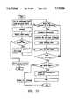
- FIG. 10is the flow chart of the whole operation in the embodiment of this invention.
- FIG. 1shows an illustrative drawing of the window (18) which is put on the conventional scanner (1).
- FIG. 2shows an illustrative drawing of the image (2) which is put on the window (18) of this invention.
- FIG. 3shows the window region according to a preferred embodiment of this invention. Its design is to set multiple rectangular fields (26), (28), (30) and (32) in a window (18). Fiducial marks (10), (12), (14) and (16) are located outside the upper left corner of each rectangular box. For this to be useful even after a 180 degree rotation, another set of fiducial marks (19), (20), (22) and (24) are located outside the lower right corner of the rectangular boxes (26), (28), (30) and (32), symmetrically. Computer program recognizes those fiducial marks automatically. Only one pair of fiducial marks is needed if the rectangular fields are set with equal distance between each other. The position of the other rectangular fields can be found be shifting the scan field with given distance.
- the design of the fiducial marks in this embodimentis a small square hole.
- a black signalis received when there is obstruction to the light transmission, and a white signal is got when the light passes through the hole.
- an "X"indicates a black point and an "O" indicates a white point.
- the pattern in the figureis an example showing the signal after scanning a small round white hole on a black background, this example is shown in a square matrix to simplify the operation of the scanner.
- FIG. 5illustrates the flow chart of the fiducial marks recognizing program, i.e. the algorithm used to find the fiducial marks.
- the main functionis to select a small area of the image and compare with the pattern of the white hole in black background (see FIG. 4), starting at the upper left corner of the image. If the patterns match each other, the coordinates of this position are recorded then terminate the job. If not, move the selection area right in one step, and repeat the comparison until the right edge of the image is encountered. Then the selection area is moved down in one step and repeat the moving and comparing until a matched pattern is found or the lower edge of the image is encountered.
- the recognition of the existence of the document imageis achieved by detecting the point in the upper left corner of the image field.
- the gray level of the detecting pointis compared with a given gray level, called threshold value. If the gray level of the detection point is greater than the threshold value, there is no document; otherwise, if the gray level of the detection point is less than the threshold value, a document is present.
- the detection of the orientation of the imageis achieved by comparing the average gray level of the left and right edges, with average gray level of the upper and lower edges. If the average gray level is high, this further means that an image is present in this area.
- FIG. 8the flow chart of the program detection of the orientation of the image. It starts by calculating the average gray level of the left and right edges, then calculating the average gray level of the upper and lower edges, then compare these two averages. The document is determined to be in the portrait orientation if the average gray level of the left and right edges is less than that of the upper and lower edges. Otherwise, the document is in a landscape orientation, if the average gray level of the left and right edge is higher than that of the upper and lower edges.
- the flow chart of the program for adjusting the scan fieldconsists of four steps.
- the main functionis to select certain area around the image to detect the gray level there and use these to adjust the scan field to avoid the shifting of the scanned image.
- the first stepis to detect the gray level of the upper edge of the selected field and compare it with a given threshold value.
- second stepcompare the gray level of the lower edge with the threshold value. If the upper edge gray level is less than the threshold value while that of the lower edge is greater than threshold value, move the field downward and go to the third step. If the upper edge gray level is greater than the threshold value while that of the lower edge is less than threshold value, move the field upward and go to the third step. Otherwise, do nothing and proceed to the third step.
- the third stepcompare the gray level of the left edge of the field with the threshold value.
- compare the right edge gray level with the threshold valueIf the left edge gray level is less than threshold value while that of the fight edge is greater than threshold value, move the field to the fight and terminate the program. If the left edge gray level is greater than the threshold value while that of the fight edge is less than threshold value, move the field to the left and terminate the program. Otherwise, do nothing and end the program.
- the flow chart of the whole scanning operationstarts by placing the rectangular fields in the scan window of the scanner. Then scan the area and search for the fiducial marks, if it fails to find the fiducial marks, display an error message and terminate the scan process. Otherwise, move to the first scan field and detect the presence of the document image. If there is no image found, then proceed to the nest scan field. Otherwise, determine the orientation of the document and adjust the scan field to compensate the shifting of the scanned image. Then move to the next scan field and repeat these procedures until the last field is complete. Finally, display the scan fields on the screen and start the scanning operation.
Landscapes
- Engineering & Computer Science (AREA)
- Multimedia (AREA)
- Signal Processing (AREA)
- Physics & Mathematics (AREA)
- General Physics & Mathematics (AREA)
- Theoretical Computer Science (AREA)
- Image Input (AREA)
- Facsimile Scanning Arrangements (AREA)
Abstract
Description
Claims (9)
Priority Applications (1)
| Application Number | Priority Date | Filing Date | Title |
|---|---|---|---|
| US08/597,666US5719386A (en) | 1996-02-07 | 1996-02-07 | High efficiency multi-image scan method |
Applications Claiming Priority (1)
| Application Number | Priority Date | Filing Date | Title |
|---|---|---|---|
| US08/597,666US5719386A (en) | 1996-02-07 | 1996-02-07 | High efficiency multi-image scan method |
Publications (1)
| Publication Number | Publication Date |
|---|---|
| US5719386Atrue US5719386A (en) | 1998-02-17 |
Family
ID=24392462
Family Applications (1)
| Application Number | Title | Priority Date | Filing Date |
|---|---|---|---|
| US08/597,666Expired - LifetimeUS5719386A (en) | 1996-02-07 | 1996-02-07 | High efficiency multi-image scan method |
Country Status (1)
| Country | Link |
|---|---|
| US (1) | US5719386A (en) |
Cited By (27)
| Publication number | Priority date | Publication date | Assignee | Title |
|---|---|---|---|---|
| WO2001035054A1 (en)* | 1999-11-12 | 2001-05-17 | Armstrong Brian S | Methods and appparatus for measuring orientation and distance |
| US6295144B1 (en) | 1997-05-08 | 2001-09-25 | Samsung Electronics Co., Ltd. | Pre-scanning method and apparatus for shuttle scanning system |
| US6384908B1 (en) | 1996-08-15 | 2002-05-07 | Go Sensors, Llc | Orientation dependent radiation source |
| US20030034393A1 (en)* | 2000-11-20 | 2003-02-20 | Chung Kevin Kwong-Tai | Electronic voting apparatus, system and method |
| US20060169778A1 (en)* | 2000-11-20 | 2006-08-03 | Chung Kevin K | Electronic voting apparatus, system and method |
| US20060202031A1 (en)* | 2001-10-01 | 2006-09-14 | Chung Kevin K | Reader for an optically readable ballot |
| US20060255145A1 (en)* | 2001-10-01 | 2006-11-16 | Chung Kevin K | Method for reading an optically readable sheet |
| US7422150B2 (en) | 2000-11-20 | 2008-09-09 | Avante International Technology, Inc. | Electronic voting apparatus, system and method |
| US20090289115A1 (en)* | 2008-04-30 | 2009-11-26 | Kevin Kwong-Tai Chung | Optically readable marking sheet and reading apparatus and method therefor |
| US7635087B1 (en) | 2001-10-01 | 2009-12-22 | Avante International Technology, Inc. | Method for processing a machine readable ballot and ballot therefor |
| US20110089236A1 (en)* | 2009-10-21 | 2011-04-21 | Kevin Kwong-Tai Chung | System and method for decoding an optically readable markable sheet and markable sheet therefor |
| US8261985B2 (en) | 2009-04-07 | 2012-09-11 | Avante Corporation Limited | Manual recount process using digitally imaged ballots |
| US20150352664A1 (en)* | 2014-06-05 | 2015-12-10 | Nlight Photonics Corporation | Laser Patterning Skew Correction |
| US20190045071A1 (en)* | 2017-08-01 | 2019-02-07 | Kabushiki Kaisha Toshiba | Image processing apparatus |
| US10295820B2 (en) | 2016-01-19 | 2019-05-21 | Nlight, Inc. | Method of processing calibration data in 3D laser scanner systems |
| US10434600B2 (en) | 2015-11-23 | 2019-10-08 | Nlight, Inc. | Fine-scale temporal control for laser material processing |
| US10464172B2 (en) | 2013-02-21 | 2019-11-05 | Nlight, Inc. | Patterning conductive films using variable focal plane to control feature size |
| US10656330B2 (en) | 2016-09-29 | 2020-05-19 | Nlight, Inc. | Use of variable beam parameters to control solidification of a material |
| US10673198B2 (en) | 2016-09-29 | 2020-06-02 | Nlight, Inc. | Fiber-coupled laser with time varying beam characteristics |
| US10673199B2 (en) | 2016-09-29 | 2020-06-02 | Nlight, Inc. | Fiber-based saturable absorber |
| US10673197B2 (en) | 2016-09-29 | 2020-06-02 | Nlight, Inc. | Fiber-based optical modulator |
| US10730785B2 (en) | 2016-09-29 | 2020-08-04 | Nlight, Inc. | Optical fiber bending mechanisms |
| US10916908B2 (en) | 2015-01-26 | 2021-02-09 | Nlight, Inc. | High-power, single-mode fiber sources |
| US10971884B2 (en) | 2015-03-26 | 2021-04-06 | Nlight, Inc. | Fiber source with cascaded gain stages and/or multimode delivery fiber with low splice loss |
| US11008644B2 (en) | 2013-02-21 | 2021-05-18 | Nlight, Inc. | Laser patterning of multi-layer structures |
| US11173548B2 (en) | 2017-04-04 | 2021-11-16 | Nlight, Inc. | Optical fiducial generation for galvanometric scanner calibration |
| US11179807B2 (en) | 2015-11-23 | 2021-11-23 | Nlight, Inc. | Fine-scale temporal control for laser material processing |
Citations (7)
| Publication number | Priority date | Publication date | Assignee | Title |
|---|---|---|---|---|
| US4736109A (en)* | 1986-08-13 | 1988-04-05 | Bally Manufacturing Company | Coded document and document reading system |
| US4760247A (en)* | 1986-04-04 | 1988-07-26 | Bally Manufacturing Company | Optical card reader utilizing area image processing |
| US4776464A (en)* | 1985-06-17 | 1988-10-11 | Bae Automated Systems, Inc. | Automated article handling system and process |
| US5410620A (en)* | 1989-08-02 | 1995-04-25 | Teiryo Sangyo Co., Ltd. | Digital data reader of digital data recording sheet |
| US5588072A (en)* | 1993-12-22 | 1996-12-24 | Canon Kabushiki Kaisha | Method and apparatus for selecting blocks of image data from image data having both horizontally- and vertically-oriented blocks |
| US5610995A (en)* | 1995-06-06 | 1997-03-11 | United Parcel Service Of America, Inc. | Method and apparatus for compressing images containing optical symbols |
| US5612524A (en)* | 1987-11-25 | 1997-03-18 | Veritec Inc. | Identification symbol system and method with orientation mechanism |
- 1996
- 1996-02-07USUS08/597,666patent/US5719386A/ennot_activeExpired - Lifetime
Patent Citations (7)
| Publication number | Priority date | Publication date | Assignee | Title |
|---|---|---|---|---|
| US4776464A (en)* | 1985-06-17 | 1988-10-11 | Bae Automated Systems, Inc. | Automated article handling system and process |
| US4760247A (en)* | 1986-04-04 | 1988-07-26 | Bally Manufacturing Company | Optical card reader utilizing area image processing |
| US4736109A (en)* | 1986-08-13 | 1988-04-05 | Bally Manufacturing Company | Coded document and document reading system |
| US5612524A (en)* | 1987-11-25 | 1997-03-18 | Veritec Inc. | Identification symbol system and method with orientation mechanism |
| US5410620A (en)* | 1989-08-02 | 1995-04-25 | Teiryo Sangyo Co., Ltd. | Digital data reader of digital data recording sheet |
| US5588072A (en)* | 1993-12-22 | 1996-12-24 | Canon Kabushiki Kaisha | Method and apparatus for selecting blocks of image data from image data having both horizontally- and vertically-oriented blocks |
| US5610995A (en)* | 1995-06-06 | 1997-03-11 | United Parcel Service Of America, Inc. | Method and apparatus for compressing images containing optical symbols |
Cited By (49)
| Publication number | Priority date | Publication date | Assignee | Title |
|---|---|---|---|---|
| US6384908B1 (en) | 1996-08-15 | 2002-05-07 | Go Sensors, Llc | Orientation dependent radiation source |
| US6295144B1 (en) | 1997-05-08 | 2001-09-25 | Samsung Electronics Co., Ltd. | Pre-scanning method and apparatus for shuttle scanning system |
| US20040233461A1 (en)* | 1999-11-12 | 2004-11-25 | Armstrong Brian S. | Methods and apparatus for measuring orientation and distance |
| WO2001035052A1 (en)* | 1999-11-12 | 2001-05-17 | Armstrong Brian S | Robust landmarks for machine vision and methods for detecting same |
| WO2001035054A1 (en)* | 1999-11-12 | 2001-05-17 | Armstrong Brian S | Methods and appparatus for measuring orientation and distance |
| US7461787B2 (en) | 2000-11-20 | 2008-12-09 | Avante International Technology, Inc. | Electronic voting apparatus, system and method |
| US7422150B2 (en) | 2000-11-20 | 2008-09-09 | Avante International Technology, Inc. | Electronic voting apparatus, system and method |
| US20060169778A1 (en)* | 2000-11-20 | 2006-08-03 | Chung Kevin K | Electronic voting apparatus, system and method |
| US20030034393A1 (en)* | 2000-11-20 | 2003-02-20 | Chung Kevin Kwong-Tai | Electronic voting apparatus, system and method |
| US7431209B2 (en) | 2000-11-20 | 2008-10-07 | Avante International Technology, Inc. | Electronic voting apparatus, system and method |
| US7614553B2 (en) | 2001-10-01 | 2009-11-10 | Avante International Technology, Inc. | Method for reading an optically readable sheet |
| US7635087B1 (en) | 2001-10-01 | 2009-12-22 | Avante International Technology, Inc. | Method for processing a machine readable ballot and ballot therefor |
| US20060255145A1 (en)* | 2001-10-01 | 2006-11-16 | Chung Kevin K | Method for reading an optically readable sheet |
| US20090020606A1 (en)* | 2001-10-01 | 2009-01-22 | Kevin Kwong-Tai Chung | Electronic voting method and system employing a machine readable ballot envelope |
| US20060202031A1 (en)* | 2001-10-01 | 2006-09-14 | Chung Kevin K | Reader for an optically readable ballot |
| US7988047B2 (en) | 2001-10-01 | 2011-08-02 | Avante International Technology, Inc. | Method for decoding an optically readable sheet |
| US7635088B2 (en) | 2001-10-01 | 2009-12-22 | Avante International Technology, Inc. | Electronic voting method and system employing a printed machine readable ballot |
| US20070170253A1 (en)* | 2001-10-01 | 2007-07-26 | Avante International Technology, Inc. | Electronic voting method and system employing a printed machine readable ballot |
| US20100170948A1 (en)* | 2001-10-01 | 2010-07-08 | Kevin Kwong-Tai Chung | Method for decoding an optically readable sheet |
| US7828215B2 (en) | 2001-10-01 | 2010-11-09 | Avante International Technology, Inc. | Reader for an optically readable ballot |
| US7975920B2 (en) | 2001-10-01 | 2011-07-12 | Avante International Technology, Inc. | Electronic voting method and system employing a machine readable ballot envelope |
| US20090289115A1 (en)* | 2008-04-30 | 2009-11-26 | Kevin Kwong-Tai Chung | Optically readable marking sheet and reading apparatus and method therefor |
| US8066184B2 (en) | 2008-04-30 | 2011-11-29 | Avante International Technology, Inc. | Optically readable marking sheet and reading apparatus and method therefor |
| US8261985B2 (en) | 2009-04-07 | 2012-09-11 | Avante Corporation Limited | Manual recount process using digitally imaged ballots |
| US8261986B2 (en) | 2009-10-21 | 2012-09-11 | Kevin Kwong-Tai Chung | System and method for decoding an optically readable markable sheet and markable sheet therefor |
| US20110089236A1 (en)* | 2009-10-21 | 2011-04-21 | Kevin Kwong-Tai Chung | System and method for decoding an optically readable markable sheet and markable sheet therefor |
| US11008644B2 (en) | 2013-02-21 | 2021-05-18 | Nlight, Inc. | Laser patterning of multi-layer structures |
| US10464172B2 (en) | 2013-02-21 | 2019-11-05 | Nlight, Inc. | Patterning conductive films using variable focal plane to control feature size |
| US20150352664A1 (en)* | 2014-06-05 | 2015-12-10 | Nlight Photonics Corporation | Laser Patterning Skew Correction |
| US10618131B2 (en)* | 2014-06-05 | 2020-04-14 | Nlight, Inc. | Laser patterning skew correction |
| US11465232B2 (en)* | 2014-06-05 | 2022-10-11 | Nlight, Inc. | Laser patterning skew correction |
| US10916908B2 (en) | 2015-01-26 | 2021-02-09 | Nlight, Inc. | High-power, single-mode fiber sources |
| US10971884B2 (en) | 2015-03-26 | 2021-04-06 | Nlight, Inc. | Fiber source with cascaded gain stages and/or multimode delivery fiber with low splice loss |
| US11179807B2 (en) | 2015-11-23 | 2021-11-23 | Nlight, Inc. | Fine-scale temporal control for laser material processing |
| US11331756B2 (en) | 2015-11-23 | 2022-05-17 | Nlight, Inc. | Fine-scale temporal control for laser material processing |
| US10434600B2 (en) | 2015-11-23 | 2019-10-08 | Nlight, Inc. | Fine-scale temporal control for laser material processing |
| US11794282B2 (en) | 2015-11-23 | 2023-10-24 | Nlight, Inc. | Fine-scale temporal control for laser material processing |
| US10739579B2 (en) | 2016-01-19 | 2020-08-11 | Nlight, Inc. | Method of processing calibration data in 3D laser scanner systems |
| US10295820B2 (en) | 2016-01-19 | 2019-05-21 | Nlight, Inc. | Method of processing calibration data in 3D laser scanner systems |
| US10673197B2 (en) | 2016-09-29 | 2020-06-02 | Nlight, Inc. | Fiber-based optical modulator |
| US10730785B2 (en) | 2016-09-29 | 2020-08-04 | Nlight, Inc. | Optical fiber bending mechanisms |
| US10673199B2 (en) | 2016-09-29 | 2020-06-02 | Nlight, Inc. | Fiber-based saturable absorber |
| US10673198B2 (en) | 2016-09-29 | 2020-06-02 | Nlight, Inc. | Fiber-coupled laser with time varying beam characteristics |
| US10663767B2 (en) | 2016-09-29 | 2020-05-26 | Nlight, Inc. | Adjustable beam characteristics |
| US10656330B2 (en) | 2016-09-29 | 2020-05-19 | Nlight, Inc. | Use of variable beam parameters to control solidification of a material |
| US11173548B2 (en) | 2017-04-04 | 2021-11-16 | Nlight, Inc. | Optical fiducial generation for galvanometric scanner calibration |
| US11032439B2 (en)* | 2017-08-01 | 2021-06-08 | Kabushiki Kaisha Toshiba | Image processing apparatus |
| US20200120226A1 (en)* | 2017-08-01 | 2020-04-16 | Kabushiki Kaisha Toshiba | Image processing apparatus |
| US20190045071A1 (en)* | 2017-08-01 | 2019-02-07 | Kabushiki Kaisha Toshiba | Image processing apparatus |
Similar Documents
| Publication | Publication Date | Title |
|---|---|---|
| US5719386A (en) | High efficiency multi-image scan method | |
| US6738154B1 (en) | Locating the position and orientation of multiple objects with a smart platen | |
| US6408094B1 (en) | Document image assessment system and method | |
| US5038393A (en) | Method of effectively reading data written on data sheet, and data reading apparatus therefor | |
| US5198907A (en) | Method and appratus for automatically locating predefined exposure areas in a scanned image | |
| US8254683B2 (en) | Code image processing method | |
| JPH03201866A (en) | Decision of picture skew angle from data including data of compressed form | |
| US20060153447A1 (en) | Characteristic region extraction device, characteristic region extraction method, and characteristic region extraction program | |
| US8630025B2 (en) | Image processing apparatus, image processing method, and image processing program recorded recording medium | |
| JPH07234915A (en) | Image recognizing device | |
| US20070013975A1 (en) | Method for automatically determining document position in a scanner window | |
| JPH05244414A (en) | Picture processor | |
| US7102786B2 (en) | Image reading apparatus and processing apparatus | |
| US6771842B1 (en) | Document image skew detection method | |
| US6556721B1 (en) | Method for image auto-cropping | |
| JPH07112237B2 (en) | Image processing method and image processing apparatus | |
| JPH0418351B2 (en) | ||
| JP5222126B2 (en) | Image processing method, image processing apparatus, and program | |
| US7375859B2 (en) | Method and apparatus for correcting scanning error in flatbed scanner | |
| JP5222127B2 (en) | Image processing apparatus, image processing method, and program | |
| EP0689168B1 (en) | Image processing method and apparatus | |
| JP3058791B2 (en) | Method of extracting figure of image recognition device | |
| EP0975146B1 (en) | Locating the position and orientation of multiple objects with a smart platen | |
| US6813382B2 (en) | Image outline determination method, image outline determination apparatus, image outline determination program storage medium, image input apparatus and image input program storage medium | |
| JP2000251010A (en) | Form reading method |
Legal Events
| Date | Code | Title | Description |
|---|---|---|---|
| AS | Assignment | Owner name:UMAX DATA SYSTEMS INC., TAIWAN Free format text:ASSIGNMENT OF ASSIGNORS INTEREST;ASSIGNORS:HSIEH, MICHAEL;HUANG, RAYMOND;REEL/FRAME:007860/0743 Effective date:19960117 | |
| STCF | Information on status: patent grant | Free format text:PATENTED CASE | |
| FPAY | Fee payment | Year of fee payment:4 | |
| FPAY | Fee payment | Year of fee payment:8 | |
| AS | Assignment | Owner name:VEUTRON CORPORATION, TAIWAN Free format text:CHANGE OF NAME;ASSIGNOR:UMAX DATA SYSTEMS INC.;REEL/FRAME:016800/0203 Effective date:20021029 | |
| AS | Assignment | Owner name:TRANSPACIFIC IP, LTD.,TAIWAN Free format text:ASSIGNMENT OF ASSIGNORS INTEREST;ASSIGNOR:VEUTRON CORPORATION;REEL/FRAME:017564/0747 Effective date:20050706 Owner name:TRANSPACIFIC IP, LTD., TAIWAN Free format text:ASSIGNMENT OF ASSIGNORS INTEREST;ASSIGNOR:VEUTRON CORPORATION;REEL/FRAME:017564/0747 Effective date:20050706 | |
| FPAY | Fee payment | Year of fee payment:12 | |
| AS | Assignment | Owner name:TRANSPACIFIC SYSTEMS, LLC, DELAWARE Free format text:ASSIGNMENT OF ASSIGNORS INTEREST;ASSIGNOR:TRANSPACIFIC IP LTD.;REEL/FRAME:023107/0267 Effective date:20090618 Owner name:TRANSPACIFIC SYSTEMS, LLC,DELAWARE Free format text:ASSIGNMENT OF ASSIGNORS INTEREST;ASSIGNOR:TRANSPACIFIC IP LTD.;REEL/FRAME:023107/0267 Effective date:20090618 | |
| AS | Assignment | Owner name:TITUSVILLE CANAVERAL LLC, DELAWARE Free format text:MERGER;ASSIGNOR:TRANSPACIFIC SYSTEMS, LLC;REEL/FRAME:030628/0681 Effective date:20130213 | |
| AS | Assignment | Owner name:INTELLECTUAL VENTURES I LLC, DELAWARE Free format text:MERGER;ASSIGNOR:TITUSVILLE CANAVERAL LLC;REEL/FRAME:030639/0330 Effective date:20130214 |