US5718713A - Surgical stent having a streamlined contour - Google Patents
Surgical stent having a streamlined contourDownload PDFInfo
- Publication number
- US5718713A US5718713AUS08/839,434US83943497AUS5718713AUS 5718713 AUS5718713 AUS 5718713AUS 83943497 AUS83943497 AUS 83943497AUS 5718713 AUS5718713 AUS 5718713A
- Authority
- US
- United States
- Prior art keywords
- stent
- leading
- curvature
- trailing
- radius
- Prior art date
- Legal status (The legal status is an assumption and is not a legal conclusion. Google has not performed a legal analysis and makes no representation as to the accuracy of the status listed.)
- Expired - Lifetime
Links
Images


Classifications
- A—HUMAN NECESSITIES
- A61—MEDICAL OR VETERINARY SCIENCE; HYGIENE
- A61F—FILTERS IMPLANTABLE INTO BLOOD VESSELS; PROSTHESES; DEVICES PROVIDING PATENCY TO, OR PREVENTING COLLAPSING OF, TUBULAR STRUCTURES OF THE BODY, e.g. STENTS; ORTHOPAEDIC, NURSING OR CONTRACEPTIVE DEVICES; FOMENTATION; TREATMENT OR PROTECTION OF EYES OR EARS; BANDAGES, DRESSINGS OR ABSORBENT PADS; FIRST-AID KITS
- A61F2/00—Filters implantable into blood vessels; Prostheses, i.e. artificial substitutes or replacements for parts of the body; Appliances for connecting them with the body; Devices providing patency to, or preventing collapsing of, tubular structures of the body, e.g. stents
- A61F2/95—Instruments specially adapted for placement or removal of stents or stent-grafts
- A61F2/958—Inflatable balloons for placing stents or stent-grafts
- A—HUMAN NECESSITIES
- A61—MEDICAL OR VETERINARY SCIENCE; HYGIENE
- A61F—FILTERS IMPLANTABLE INTO BLOOD VESSELS; PROSTHESES; DEVICES PROVIDING PATENCY TO, OR PREVENTING COLLAPSING OF, TUBULAR STRUCTURES OF THE BODY, e.g. STENTS; ORTHOPAEDIC, NURSING OR CONTRACEPTIVE DEVICES; FOMENTATION; TREATMENT OR PROTECTION OF EYES OR EARS; BANDAGES, DRESSINGS OR ABSORBENT PADS; FIRST-AID KITS
- A61F2/00—Filters implantable into blood vessels; Prostheses, i.e. artificial substitutes or replacements for parts of the body; Appliances for connecting them with the body; Devices providing patency to, or preventing collapsing of, tubular structures of the body, e.g. stents
- A61F2/82—Devices providing patency to, or preventing collapsing of, tubular structures of the body, e.g. stents
- A61F2/86—Stents in a form characterised by the wire-like elements; Stents in the form characterised by a net-like or mesh-like structure
- A61F2/90—Stents in a form characterised by the wire-like elements; Stents in the form characterised by a net-like or mesh-like structure characterised by a net-like or mesh-like structure
- A61F2/91—Stents in a form characterised by the wire-like elements; Stents in the form characterised by a net-like or mesh-like structure characterised by a net-like or mesh-like structure made from perforated sheets or tubes, e.g. perforated by laser cuts or etched holes
- A—HUMAN NECESSITIES
- A61—MEDICAL OR VETERINARY SCIENCE; HYGIENE
- A61F—FILTERS IMPLANTABLE INTO BLOOD VESSELS; PROSTHESES; DEVICES PROVIDING PATENCY TO, OR PREVENTING COLLAPSING OF, TUBULAR STRUCTURES OF THE BODY, e.g. STENTS; ORTHOPAEDIC, NURSING OR CONTRACEPTIVE DEVICES; FOMENTATION; TREATMENT OR PROTECTION OF EYES OR EARS; BANDAGES, DRESSINGS OR ABSORBENT PADS; FIRST-AID KITS
- A61F2/00—Filters implantable into blood vessels; Prostheses, i.e. artificial substitutes or replacements for parts of the body; Appliances for connecting them with the body; Devices providing patency to, or preventing collapsing of, tubular structures of the body, e.g. stents
- A61F2/82—Devices providing patency to, or preventing collapsing of, tubular structures of the body, e.g. stents
- A61F2/86—Stents in a form characterised by the wire-like elements; Stents in the form characterised by a net-like or mesh-like structure
- A61F2/90—Stents in a form characterised by the wire-like elements; Stents in the form characterised by a net-like or mesh-like structure characterised by a net-like or mesh-like structure
- A61F2/91—Stents in a form characterised by the wire-like elements; Stents in the form characterised by a net-like or mesh-like structure characterised by a net-like or mesh-like structure made from perforated sheets or tubes, e.g. perforated by laser cuts or etched holes
- A61F2/915—Stents in a form characterised by the wire-like elements; Stents in the form characterised by a net-like or mesh-like structure characterised by a net-like or mesh-like structure made from perforated sheets or tubes, e.g. perforated by laser cuts or etched holes with bands having a meander structure, adjacent bands being connected to each other
- A—HUMAN NECESSITIES
- A61—MEDICAL OR VETERINARY SCIENCE; HYGIENE
- A61L—METHODS OR APPARATUS FOR STERILISING MATERIALS OR OBJECTS IN GENERAL; DISINFECTION, STERILISATION OR DEODORISATION OF AIR; CHEMICAL ASPECTS OF BANDAGES, DRESSINGS, ABSORBENT PADS OR SURGICAL ARTICLES; MATERIALS FOR BANDAGES, DRESSINGS, ABSORBENT PADS OR SURGICAL ARTICLES
- A61L27/00—Materials for grafts or prostheses or for coating grafts or prostheses
- A61L27/02—Inorganic materials
- A61L27/04—Metals or alloys
- A—HUMAN NECESSITIES
- A61—MEDICAL OR VETERINARY SCIENCE; HYGIENE
- A61F—FILTERS IMPLANTABLE INTO BLOOD VESSELS; PROSTHESES; DEVICES PROVIDING PATENCY TO, OR PREVENTING COLLAPSING OF, TUBULAR STRUCTURES OF THE BODY, e.g. STENTS; ORTHOPAEDIC, NURSING OR CONTRACEPTIVE DEVICES; FOMENTATION; TREATMENT OR PROTECTION OF EYES OR EARS; BANDAGES, DRESSINGS OR ABSORBENT PADS; FIRST-AID KITS
- A61F2/00—Filters implantable into blood vessels; Prostheses, i.e. artificial substitutes or replacements for parts of the body; Appliances for connecting them with the body; Devices providing patency to, or preventing collapsing of, tubular structures of the body, e.g. stents
- A61F2/02—Prostheses implantable into the body
- A61F2/04—Hollow or tubular parts of organs, e.g. bladders, tracheae, bronchi or bile ducts
- A61F2/06—Blood vessels
- A61F2002/068—Modifying the blood flow model, e.g. by diffuser or deflector
- A—HUMAN NECESSITIES
- A61—MEDICAL OR VETERINARY SCIENCE; HYGIENE
- A61F—FILTERS IMPLANTABLE INTO BLOOD VESSELS; PROSTHESES; DEVICES PROVIDING PATENCY TO, OR PREVENTING COLLAPSING OF, TUBULAR STRUCTURES OF THE BODY, e.g. STENTS; ORTHOPAEDIC, NURSING OR CONTRACEPTIVE DEVICES; FOMENTATION; TREATMENT OR PROTECTION OF EYES OR EARS; BANDAGES, DRESSINGS OR ABSORBENT PADS; FIRST-AID KITS
- A61F2/00—Filters implantable into blood vessels; Prostheses, i.e. artificial substitutes or replacements for parts of the body; Appliances for connecting them with the body; Devices providing patency to, or preventing collapsing of, tubular structures of the body, e.g. stents
- A61F2/02—Prostheses implantable into the body
- A61F2/30—Joints
- A61F2002/30001—Additional features of subject-matter classified in A61F2/28, A61F2/30 and subgroups thereof
- A61F2002/30108—Shapes
- A61F2002/3011—Cross-sections or two-dimensional shapes
- A61F2002/30182—Other shapes
- A61F2002/30187—D-shaped or half-disc-shaped
- A—HUMAN NECESSITIES
- A61—MEDICAL OR VETERINARY SCIENCE; HYGIENE
- A61F—FILTERS IMPLANTABLE INTO BLOOD VESSELS; PROSTHESES; DEVICES PROVIDING PATENCY TO, OR PREVENTING COLLAPSING OF, TUBULAR STRUCTURES OF THE BODY, e.g. STENTS; ORTHOPAEDIC, NURSING OR CONTRACEPTIVE DEVICES; FOMENTATION; TREATMENT OR PROTECTION OF EYES OR EARS; BANDAGES, DRESSINGS OR ABSORBENT PADS; FIRST-AID KITS
- A61F2/00—Filters implantable into blood vessels; Prostheses, i.e. artificial substitutes or replacements for parts of the body; Appliances for connecting them with the body; Devices providing patency to, or preventing collapsing of, tubular structures of the body, e.g. stents
- A61F2/82—Devices providing patency to, or preventing collapsing of, tubular structures of the body, e.g. stents
- A61F2/86—Stents in a form characterised by the wire-like elements; Stents in the form characterised by a net-like or mesh-like structure
- A61F2/90—Stents in a form characterised by the wire-like elements; Stents in the form characterised by a net-like or mesh-like structure characterised by a net-like or mesh-like structure
- A61F2/91—Stents in a form characterised by the wire-like elements; Stents in the form characterised by a net-like or mesh-like structure characterised by a net-like or mesh-like structure made from perforated sheets or tubes, e.g. perforated by laser cuts or etched holes
- A61F2/915—Stents in a form characterised by the wire-like elements; Stents in the form characterised by a net-like or mesh-like structure characterised by a net-like or mesh-like structure made from perforated sheets or tubes, e.g. perforated by laser cuts or etched holes with bands having a meander structure, adjacent bands being connected to each other
- A61F2002/91533—Stents in a form characterised by the wire-like elements; Stents in the form characterised by a net-like or mesh-like structure characterised by a net-like or mesh-like structure made from perforated sheets or tubes, e.g. perforated by laser cuts or etched holes with bands having a meander structure, adjacent bands being connected to each other characterised by the phase between adjacent bands
- A61F2002/91541—Adjacent bands are arranged out of phase
- A—HUMAN NECESSITIES
- A61—MEDICAL OR VETERINARY SCIENCE; HYGIENE
- A61F—FILTERS IMPLANTABLE INTO BLOOD VESSELS; PROSTHESES; DEVICES PROVIDING PATENCY TO, OR PREVENTING COLLAPSING OF, TUBULAR STRUCTURES OF THE BODY, e.g. STENTS; ORTHOPAEDIC, NURSING OR CONTRACEPTIVE DEVICES; FOMENTATION; TREATMENT OR PROTECTION OF EYES OR EARS; BANDAGES, DRESSINGS OR ABSORBENT PADS; FIRST-AID KITS
- A61F2/00—Filters implantable into blood vessels; Prostheses, i.e. artificial substitutes or replacements for parts of the body; Appliances for connecting them with the body; Devices providing patency to, or preventing collapsing of, tubular structures of the body, e.g. stents
- A61F2/82—Devices providing patency to, or preventing collapsing of, tubular structures of the body, e.g. stents
- A61F2/86—Stents in a form characterised by the wire-like elements; Stents in the form characterised by a net-like or mesh-like structure
- A61F2/90—Stents in a form characterised by the wire-like elements; Stents in the form characterised by a net-like or mesh-like structure characterised by a net-like or mesh-like structure
- A61F2/91—Stents in a form characterised by the wire-like elements; Stents in the form characterised by a net-like or mesh-like structure characterised by a net-like or mesh-like structure made from perforated sheets or tubes, e.g. perforated by laser cuts or etched holes
- A61F2/915—Stents in a form characterised by the wire-like elements; Stents in the form characterised by a net-like or mesh-like structure characterised by a net-like or mesh-like structure made from perforated sheets or tubes, e.g. perforated by laser cuts or etched holes with bands having a meander structure, adjacent bands being connected to each other
- A61F2002/9155—Adjacent bands being connected to each other
- A61F2002/91558—Adjacent bands being connected to each other connected peak to peak
- A—HUMAN NECESSITIES
- A61—MEDICAL OR VETERINARY SCIENCE; HYGIENE
- A61F—FILTERS IMPLANTABLE INTO BLOOD VESSELS; PROSTHESES; DEVICES PROVIDING PATENCY TO, OR PREVENTING COLLAPSING OF, TUBULAR STRUCTURES OF THE BODY, e.g. STENTS; ORTHOPAEDIC, NURSING OR CONTRACEPTIVE DEVICES; FOMENTATION; TREATMENT OR PROTECTION OF EYES OR EARS; BANDAGES, DRESSINGS OR ABSORBENT PADS; FIRST-AID KITS
- A61F2/00—Filters implantable into blood vessels; Prostheses, i.e. artificial substitutes or replacements for parts of the body; Appliances for connecting them with the body; Devices providing patency to, or preventing collapsing of, tubular structures of the body, e.g. stents
- A61F2/82—Devices providing patency to, or preventing collapsing of, tubular structures of the body, e.g. stents
- A61F2/86—Stents in a form characterised by the wire-like elements; Stents in the form characterised by a net-like or mesh-like structure
- A61F2/90—Stents in a form characterised by the wire-like elements; Stents in the form characterised by a net-like or mesh-like structure characterised by a net-like or mesh-like structure
- A61F2/91—Stents in a form characterised by the wire-like elements; Stents in the form characterised by a net-like or mesh-like structure characterised by a net-like or mesh-like structure made from perforated sheets or tubes, e.g. perforated by laser cuts or etched holes
- A61F2/915—Stents in a form characterised by the wire-like elements; Stents in the form characterised by a net-like or mesh-like structure characterised by a net-like or mesh-like structure made from perforated sheets or tubes, e.g. perforated by laser cuts or etched holes with bands having a meander structure, adjacent bands being connected to each other
- A61F2002/9155—Adjacent bands being connected to each other
- A61F2002/91566—Adjacent bands being connected to each other connected trough to trough
- A—HUMAN NECESSITIES
- A61—MEDICAL OR VETERINARY SCIENCE; HYGIENE
- A61F—FILTERS IMPLANTABLE INTO BLOOD VESSELS; PROSTHESES; DEVICES PROVIDING PATENCY TO, OR PREVENTING COLLAPSING OF, TUBULAR STRUCTURES OF THE BODY, e.g. STENTS; ORTHOPAEDIC, NURSING OR CONTRACEPTIVE DEVICES; FOMENTATION; TREATMENT OR PROTECTION OF EYES OR EARS; BANDAGES, DRESSINGS OR ABSORBENT PADS; FIRST-AID KITS
- A61F2230/00—Geometry of prostheses classified in groups A61F2/00 - A61F2/26 or A61F2/82 or A61F9/00 or A61F11/00 or subgroups thereof
- A61F2230/0002—Two-dimensional shapes, e.g. cross-sections
- A61F2230/0004—Rounded shapes, e.g. with rounded corners
- A61F2230/0013—Horseshoe-shaped, e.g. crescent-shaped, C-shaped, U-shaped
- A—HUMAN NECESSITIES
- A61—MEDICAL OR VETERINARY SCIENCE; HYGIENE
- A61F—FILTERS IMPLANTABLE INTO BLOOD VESSELS; PROSTHESES; DEVICES PROVIDING PATENCY TO, OR PREVENTING COLLAPSING OF, TUBULAR STRUCTURES OF THE BODY, e.g. STENTS; ORTHOPAEDIC, NURSING OR CONTRACEPTIVE DEVICES; FOMENTATION; TREATMENT OR PROTECTION OF EYES OR EARS; BANDAGES, DRESSINGS OR ABSORBENT PADS; FIRST-AID KITS
- A61F2230/00—Geometry of prostheses classified in groups A61F2/00 - A61F2/26 or A61F2/82 or A61F9/00 or A61F11/00 or subgroups thereof
- A61F2230/0002—Two-dimensional shapes, e.g. cross-sections
- A61F2230/0028—Shapes in the form of latin or greek characters
- A61F2230/0034—D-shaped
Definitions
- the following inventionrelates to surgical stents of a generally tubular configuration which can be surgically implanted into a body lumen, such as an artery, and be radially expanded to support the lumen. More specifically, this invention relates to radially expandable surgical stents which exhibit an inner surface which has a streamlined contour and a finely polished surface to minimize disruption of bodily fluid flow through the lumen.
- Surgical stentshave long been known which can be surgically implanted into a body lumen, such as an artery, to reinforce, support, repair or otherwise enhance the performance of the lumen.
- a body lumensuch as an artery
- the stentonce in place, reinforces that portion of the artery allowing normal blood flow to occur through the artery.
- One form of stentwhich is particularly desirable for implantation in arteries and other body lumens is a tubular stent which is formed as a complete tubular cylinder and can be radially expanded from a first smaller diameter to a second larger diameter.
- Such radially expandable stentscan be inserted into the artery by being located on a catheter and fed internally through the arterial pathways of the patient until the unexpanded stent is located where desired.
- the catheteris fitted with a balloon or other expansion mechanism which exerts a radial pressure outward on the stent causing the stent to expand radially to a larger diameter.
- Such expandable stentsexhibit sufficient rigidity after being expanded that they will remain expanded after the catheter has been removed.
- Radially expandable stentscome in a variety of different configurations to provide optimal performance to various different particular circumstances.
- LauU.S. Pat. Nos. 5,514,154, 5,421,955, and 5,242,399
- BaracciU.S. Pat. No. 5,531,741
- GaterudU.S. Pat. No. 5,522,882
- GianturcoU.S. Pat. Nos. 5,507,771 and 5,314,444
- TerminU.S. Pat. No. 5,496,27
- LaneU.S. Pat. No. 5,494,029
- MaedaU.S. Pat. No. 5,507,767)
- MarinU.S. Pat. No.
- thrombusa phenomenon where a fibrous clot forms within cracks and other irregularities in the surface finish of an implanted object (such as a stent) is enhanced when the surfaces of the stent are not finely polished.
- turbulenceis introduced into the blood.
- plaque and other depositsare provided with a site for collection and potential narrowing of the arteries and restriction of blood flow this plaque buildup adjacent an implanted object (such as a stent) is referred to as "restenosis.”
- the radially expandable surgical stent of this inventionexhibits an overall tubular cylindrical hollow seamless contour which can feature any of a variety of different arrangements for individual elements and segments forming the stent.
- the various different segments of the stenthave a generally elongate, substantially constant cross-sectional contour which can either be oriented to extend axially, circumferentially, or some combination thereof, with each segment located between an inner diameter of the stent and an outer diameter of the stent.
- Each segmentincludes an outer surface coextensive with the outer diameter of the stent and an inner surface coextensive with the inner diameter of the stent.
- Each segmentalso includes lateral surfaces extending between the inner surface and the outer surface which can either be a leading surface on an upstream side of the segment, a trailing surface on a downstream side of the segment, or a lateral surface generally aligned axially with the stent.
- each segment of the stentis extensively streamlined to minimize disruption of bodily fluid flow through the body lumen.
- the inner surfaceincludes an inner leading edge and an inner trailing edge bordering the inner surface.
- Each inner edgeis defined by an inner curve having a relatively large radius of curvature when compared to the radii of curvature exhibited by outer edges adjacent the outer surface of each stent segment. Because the inner edges have a large radius of curvature, they do not present any abrupt transition in flow for bodily fluids passing over the inner surface of the stent segment, particularly when the stent segment is aligned circumferentially with bodily fluid flow passing adjacent the inner surface from a leading inner edge to a trailing inner edge.
- each stent segmentare configured to have a surface finish which is free from abrupt transitions and irregularities, such as prominences extending more than five micro inches above adjacent portions of the surrounding surface. Smooth flow of blood or other bodily fluids over the surfaces of the stent can thus be preserved and a risk of medical complications such as restenosis and thrombus can be minimized.
- a primary object of the present inventionis to provide a radially expandable surgical stent which has a generally cylindrical contour with an inner diameter defined by inner surfaces of segments forming the stent and an outer diameter defined by outer surfaces of the segments forming the stent, the inner surfaces having a streamlined contour to minimize disruption of blood flow passing over segments of the stent when the stent is implanted within an artery or other body lumen.
- Another object of the present inventionis to provide a surgical stent which minimizes medical complications such as restenosis and thrombus adjacent the stent.
- Another object of the present inventionis to provide a radially expandable surgical stent which has a finish smoothness which minimizes medical complications such as restenosis and thrombus adjacent the stent when the stent is implanted within an artery or other body lumen.
- Another object of the present inventionis to provide a surgical stent which can support a body lumen while minimizing disruption of flow of bodily fluids through the lumen.
- Another object of the present inventionis to provide a surgical stent which is reversible and can be implanted in two distinct orientations rotated 180° from each other without altering performance of the surgical stent.
- Another object of the present inventionis to provide a surgical stent which features an inner surface which has edges with greater radii of curvature than radii of curvature of outer edges bordering an outer surface of segments of the stent, such that disruption to blood flow within a body lumen in which the stent is implanted is minimized and the outer surface of the stent is securely held adjacent a wall of the lumen.
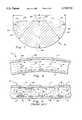
- FIG. 1is a perspective view of a radially expandable surgical stent featuring the streamlined contour of this invention.
- FIG. 2is a cylindrical projection of an alternative stent of that which is shown in FIG. 1 which also features the streamlined contour of this invention.
- FIG. 3is a perspective view of a stent segment representative of stent segments of another alternative stent to that which is shown in FIG. 1.
- FIG. 4is a perspective view of a stent segment similar to that which is shown in FIG. 3, but exhibiting a contour found in many representative prior art stents.
- FIG. 5is a full sectional view taken along line 5--5 of FIG. 1, 2 or 3 revealing a specific contour of surfaces of the stem segments according to this invention.
- FIG. 6is a full sectional view taken along line 6--6 of FIG. 4 revealing details of a typical contour of a representative prior art stent segment.
- FIG. 7is a full sectional view similar to that which is shown in FIG. 5 and further revealing details of the contour of segments forming a stent according to this invention.
- FIG. 8is a full sectional view of a stent featuring the preferred cross-sectional contour of this invention and shown implanted within a lumen, such as an artery.
- FIG. 9is a full sectional view of a lumen, such as an artery, with a prior art stent implanted therein.
- reference numeral 10is directed to a radially expandable surgical stent (FIG. 1) for implantation within a body lumen L (FIG. 8) and to which the specific contour of this invention can be applied.
- a stentsuch as the surgical stent 10 is formed from multiple stent segments, such as the stent segments 40 (FIG. 3) which feature a particular cross-sectional contour (FIG. 5).
- This contouris characterized by having an inner surface 44 which is dissimilar to an outer surface 42 such that the inner surface 44 is streamlined to minimize disruption of bodily fluid flow passing over the inner surface 44 when the stent 10 is implanted within a body lumen L (FIG. 8).
- Each stent segment 40is an elongate construct of substantially constant cross-sectional generally rectangular form, having an outer surface 42 opposite an inner surface 44. Two lateral side surfaces including a leading surface 46 and a trailing surface 48 extend between the inner surface 44 and the outer surface 42.
- the inner surface 44is provided with an inner leading edge 54 and an inner trailing edge 56 which are defined by an inner leading curve 60 and an inner trailing curve 62, respectively, with sufficiently high radii of curvature 70, 72 (FIG. 7) that the inner surface 44 is highly streamlined between the inner leading edge 54 and the inner trailing edge 56.
- the outer surface 42extends between two side edges including an outer leading edge 50 and an outer trailing edge 52.
- the outer leading edge 50is defined by an outer leading curve 64 and the outer trailing edge 52 is defined by an inner trailing curve 62.
- the inner leading curve 60 and inner trailing curve 62are have radii of curvature 74, 76 (FIG. 7) which are less than the radii of curvature 70, 72 of the inner leading curve 60 and the inner trailing curve 62 (FIG. 5).
- the stent segment 40thus has a contour which presents a highly streamlined gradually curving surface for passage of bodily fluid B (FIG. 8) there over and the outer surface 42 presents a more abrupt contour for secure positioning adjacent an inner surface S of the body lumen L (FIG. 8).
- FIGS. 1-3details of the radially expandable surgical stent 10 and its alternatives 20, 30 are described.
- the contour featured by this invention(FIG. 5) can be beneficially incorporated into surgical stents of a variety of different configurations, and stents of a variety of different materials, including radially expandable metallic stents formed of surgical steel, nickel titanium, polyhydrocarbons, metallic alloys or other implantable materials.
- the radially expandable surgical stent 10(FIG. 1) can exhibit streamlined segments having the contour of the stent segment 40 shown in FIG. 5, as represented by section lines 5--5.
- the surgical stent 10is formed from a series of separate circumferential elements 12 passing circumferentially, along arrow C, entirely around the cylindrical radially expandable surgical stent 10, preferably in a seamless manner.
- Axial elements 14, extending along arrow A,are affixed between adjacent circumferential elements 12 to tie the circumferential elements 12 together and form the stent 10 as a single tubular unit.
- the inner surface 44faces radially inward toward a central axis of the stent 10 and the outer surface 42 faces radially outward (along arrow R) away from a central axis of the stent 10.
- the surgical stent 10can beneficially support a body lumen L (FIG. 8) with individual stent segments 40 having a minimal effect on blood/fluid flow B through a body lumen L, such as an artery.
- an alternative stent 20is shown (FIG. 2) exhibiting the unique contour of this invention.
- a series of serpentine circumferential elements 22are oriented circumferentially surrounding the alternative stent 20, along arrow C.
- Axial elements 24are oriented axially, aligned with arrow A, and tie adjacent circumferential elements 22 together.
- Angled elements 26replace axial elements 24 between some pairs of circumferential elements 22 to provide additional flexibility to the alternative stent 20, as shown by section line 5--5 of FIG. 2.
- the streamlined contour of the stent segment 40 of FIG. 5can be incorporated into the alternative stent 20 to provide the benefits of the contour of the stent segment 40 to the alternative stent 20 in a manner similar to that described above with respect to the surgical stent 10 of FIG. 1.
- FIG. 3Another alternative stent 30 (FIG. 3) is designed with stent segments 40 including circumferential elements 32 extending in a serpentine pattern circumferentially, along arrow C around the stent 30 with axial elements 34 joining adjacent circumferential elements 32.
- the axial element 34joins to the circumferential element 32 adjacent a crest 36 in the circumferential element 32.
- such stents, represented by reference numeral 30'are common in the prior art which feature stent segments 40' but which lack the particular contour of the stent segment 40 of this invention.
- the circumferential elements 32 of the alternative stent 30 and the axial elements 34 of the alternative stent 30can similarly be provided with the unique contour exhibited in FIG. 5, as represented by section line 5--5 shown in FIG. 3.
- the stent segment 40is oriented axially along arrow A, blood/body fluid flow B over the inner surface 44 of the stent segment 40 is rotated 90° when compared to the orientation of the stent segment 40 and inner surface 44 when the circumferential element 32 in which the inner surface 44 is located extends circumferentially, as shown in FIGS. 1 and 2 by section lines 5--5.
- the stent segment 40is an elongate substantially rigid construct having a substantially constant cross-section as represented in FIG. 5. This cross-section exhibits a contour which is streamlined to optimize blood/body fluid flow B (FIG. 8) over the inner surface 44 of the stent segment 40.
- the stent segment 40is somewhat rectangular in cross-section except that comers of the cross-section of the stent segment 40 are curved to varying degrees, altering the cross-sectional contour of the stent segment 40 away from what would be a more particularly rectangular contour.
- an outer surface 42is presented forming one surface of the stent segment 40, substantially coextensive with an outer diameter of the surgical stent 10, or alternative stents 20, 30.
- An inner surface 44is oriented opposite the outer surface 42.
- the inner surface 42is coextensive with an inner diameter of the stents 10, 20, 30 and is roughly parallel to the outer surface 42. Because the inner surface 44 is highly rounded the inner surface 44 is actually only parallel to the outer surface 42 adjacent a middle region of the inner surface 44.
- Two lateral side surfaces 46, 48extend between the inner surface 44 and the outer surface 42 and form the remaining two sides of the somewhat rectangular stent segment 40.
- the lateral side surfaces 46, 48include a leading surface 46 and a trailing surface 48. While the leading surface 46 is oriented facing upstream much of the time when a stent such as the surgical stent 10, fitted with the stent segment 40 of this invention is implanted within a body lumen L (FIG. 8), it is also possible that the leading surface 46 can in fact be oriented parallel to a direction of flow of blood/fluid flow B within a body lumen L if the stent segment 40 is oriented axially, such as is shown in FIG. 3 for the alternative stent 30.
- the trailing surface 48while often facing downstream when incorporated into a stent 10 implanted within a body lumen L, can have other orientations when incorporated into stents of different configurations.
- the terminology “leading” and “trailing”is not intended to limit the orientation in which these lateral side surfaces 46, 48 can be oriented.
- the outer surface 42extends between an outer leading edge 50 and an outer trailing edge 52.
- the outer leading edge 50defines a transition between the outer surface 42 and the leading surface 46.
- the outer trailing edge 52defines a transition between the outer surface 42 and the trailing surface 48.
- the outer surface 42is preferably substantially planar between the outer leading edge 50 and the outer trailing edge 52.
- the inner surface 44extends between an inner leading edge 54 and an inner trailing edge 56.
- the inner surface 44preferably has a small substantially planar area at a mid point between the inner leading edge 54 and the inner trailing edge 56 which is substantially parallel to the outer surface 42.
- a thickness T of the stent segment 40is defined by the distance between the outer surface 42 and the inner surface 44.
- the inner surface 44can lack any planar region but rather curve continuously between the inner leading edge 54 and the inner trailing edge 56 with the thickness T of the stent segment 40 defined by a distance between the outer surface 42 and a mid point in the inner surface 44 between the inner leading edge 54 and the inner trailing edge 56, where the thickness T of the stent segment 40 is at a maximum.
- the leading surface 46 and trailing surface 48are preferably mirror images of each other and extend between the inner surface 44 and outer surface 42, smoothly joining the inner surface 44 with the outer surface 42 without any abrupt transitions between the outer surface 42 and the inner surface 44.
- the leading surface 46 and trailing surface 48preferably do not have any planar regions thereon, but rather continuously curve between the inner surface 44 and the outer surface 42.
- the stent segment 40thus has each surface 42, 44, 46, 48 joining to adjacent surfaces through edges 50, 52, 54, 56, somewhat analogous to the four comers of a rectangle.
- the inner leading edge 54has a contour specifically defined by an inner leading curve 60 extending from the leading surface 46 to the inner surface 44.
- the inner trailing edge 56has its contour defined by an inner trailing curve 62 extending from the inner surface 44 to the trailing surface 48.
- the inner curves 60, 62are free of abrupt transitions, but rather provide a smooth transition between the lateral side surfaces 46, 48 and the inner surface 44.
- the inner curves 60, 62are exact mirror images of each other.
- each curve 60, 62is provided with a radius of curvature including the inner leading radius of curvature 70 and the inner trailing radius of curvature 72.
- Each inner radius of curvature 70, 72extends from a center of curvature such as the inner leading center of curvature 80 or the inner trailing center of curvature 82.
- the exact radii of curvature for the inner curves 60, 62 and the centers of curvature 80, 82 for the inner curves 60, 62can be varied somewhat to conform to the particular design parameters of the application in which the stent segment 40 is to be utilized.
- Factors to consider in the design of the contour for the inner curves 60, 62 and the selection of the radii of curvature 70, 72 and the centers of curvature 80, 82include the desired coefficient of drag between the stent segment 40 and the fluid passing adjacent thereto, the viscosity of the fluid intended to be passing adjacent thereto, the diameter of the stent 10 in which the stent segment 40 is located, the extent to which the stent 10 is expected to embed itself into inner surfaces S of the body lumen L in which the stent 10 is implanted (FIG. 8), and other design parameters relevant to the particular application in which the stent 10 is to be utilized.
- radii of curvature 70, 72it is considered preferable for many applications to form the radii of curvature 70, 72 to have a size greater than the size of the thickness T of the stent segment 40, such that the centers of curvature 80, 82 are located above the outer surface 42 of the stent segment 40. For instance, when a thickness T of the stent segment 40 is 0.003 inches, radii of curvature 70, 72 for the inner curves 60, 62 can be 0.004 inches or greater.
- the inner curves 60, 62While useful in illustrating the specific contour of the inner curves 60, 62, it is not required that the inner curves 60, 62 have constant radii of curvature 70, 72 or a constant position for the centers of curvature 80, 82. Rather, it is preferable that the inner curves 60, 62 in fact be a "French" curve without a constant radius of curvature or an exact fixed position for a center of curvature. When the inner curves 60, 62 exhibit such a French curve contour, the radii of curvature 70, 72 are initially smaller adjacent the lateral side surfaces 46, 48 and the centers of curvature 80, 82 are initially closer to the inner surface 44.
- the radii of curvature 70, 72increase and the position of the centers of curvature 80, 82 move away from the inner surface 44.
- the resulting contours of the inner curves 60, 62are somewhat analogous to streamlined surfaces found effective in minimizing coefficients of drag.
- the outer leading edge 50 and outer trailing edge 52 of the outer surface 42are defined by an outer leading curve 64 and an outer trailing curve 66, respectively.
- the outer curves 64, 66are similar to each other but contrasted with the inner curves 60, 62 adjacent the inner surface 44. Specifically, the outer curves 64, 66 are defined by an outer leading radius of curvature 76 and an outer trailing radius of curvature 78 distinct from the radii of curvature 70, 72 of the inner curves 60, 62. Additionally, the outer curves 64, 66 are centered upon an outer leading center of curvature 86 and an outer trailing center of curvature 88 which are closer to the outer curves 66, 68 than is the case with the inner curves 60, 62.
- the outer curves 64, 66are similar in contour to each other and exhibit fixed radii of curvature 74, 76 which are less than half of a size of the thickness T of the stent segment 40. Unlike the inner curves 60, 62, the outer curves 64, 66 preferably exhibit radii of curvature 74, 76 which are constant in size and with fixed centers of curvature 84, 86.
- outer curves 64, 66are configured to rest against the inner surface S of the lumen L (FIG. 8), such as an artery, streamlining of the outer curves 64, 66 is not a priority. Rather, it is beneficial to provide the outer curves 64, 66 with a sufficiently smooth surface that no sharp corner is presented at the outer leading edge 50 and outer trailing edge 52 which could irritate the tissues forming the inner surface S of the lumen L and potentially stimulate thrombus or damage to the inner surface S of the lumen L.
- the outer curves 64, 66are sufficiently abrupt to allow the outer surface 42 to securely engage the inner surface S of the lumen L and resist displacement of the stent 10 longitudinally along the lumen L away from the stent's original and desired position.
- the lateral side surfaces 46, 48are preferably spaced apart by a width W which is defined as the dimension of greatest distance between the leading surface 46 and the trailing surface 48 of the stent segment 40.
- This maximum width W pointalso defines a transition where the contour of the outer curves 64, 66 transition to the contours of the inner curves 60, 62 for embodiments where no planar leading surface 46 or trailing surface 48 is provided.
- the outer curves 64, 66can gradually transition into the inner curves 60, 62 by having the radii of curvature 70, 72 of the inner curves 60, 62 match the radii of curvature 74, 76 of the outer curves 64, 66 adjacent this maximum width W point.
- the radii of curvature 70, 72 of the inner curve 60, 62would then begin to increase as the inner curves 60, 62 continue toward a middle of the inner surface 44. Simultaneously, the centers of curvature 80, 82 would begin to migrate from the location of the centers of curvature 84, 86 of the outer curves 64, 66 to their positions above the outer surface 42.
- a finish of the surfaces 42, 44, 46, 48be particularly smooth to minimize prominences which could cause irritation for tissues forming the inner surface S of the lumen L or which could disrupt blood/fluid flow B (FIG. 8) or provide sites at which plaque P, leading to restenosis or thrombus H could occur, as shown in FIG. 9.
- prior art stent segments 40'are typically substantially rectangular in cross-section with a substantially planar outer surface 42' parallel to and spaced from a substantially planar inner surface 44'.
- a leading surface 46'is substantially planar and parallel to and spaced from a substantially planar trailing surface 48'.
- Edges 50', 52', 54', 56'generally correspond to edges 50, 52, 54, 56 in the stent segment 40 of this invention.
- Such prior art stent segments 40'not only lack the particular streamlining and contouring discussed above with regard to the stent segment 40, but additionally exhibit a relatively high degree of irregularities in their surface finish, lacking a smoothness desirable for optimal performance of the stent 10.
- many stent segments 40get etched and pitted by corrosive materials utilized to form and polish the stents (FIG. 6). While such irregularities are typically microscopic and only visible with image magnifying equipment, the surfaces are sufficiently irregular (i.e. irregularities larger than five micro inches) that they cause irritation to tissues forming the inner surfaces S of lumens L in which the stents are implanted (FIG. 9).
- the surface finishhave a smoothness which eliminates prominences greater than five micro inches and preferably less than two to three micro inches.
- a stent 10 featuring stent segments 40 of this inventionis implanted into a lumen L (FIG. 8) with the stent segments 40 embedding slightly into the inner surface S of the lumen L and supporting the lumen L, blood/fluid flow B is only slightly disrupted and restenosis and plaque buildup is minimized.
- prior art stentsare implanted (FIG. 9) stent segments 40 having more abrupt contours cause disruption in the blood/fluid flow B producing eddies E which further disrupt blood/fluid flow B and encourage the formation of plaque P, leading to restenosis, along the inner surface S at various locations along the inner surface S.
- Thrombus His also stimulated by irregularities in surface finish exhibited by stent segments 40' of prior art stents.
- the stent 10 featuring the stent segment 40can be reversed 180° with similar function in either orientation.
- the inner surface 44can be provided with a more airfoil-like asymmetrical contour which does not provide the leading surface 46 and trailing surface 48 as mirror images of each other, but rather provides the leading surface 46 with a smaller radius of curvature and the trailing surface 48 with a larger radius of curvature or a tapering gradual slope, somewhat analogous to that of a tear drop in cross-section.
- Such an asymmetrical surgical stentwould necessarily only benefit from its form when implanted in a particular direction with regard to blood/fluid flow B through the lumen L.
Landscapes
- Health & Medical Sciences (AREA)
- Engineering & Computer Science (AREA)
- Biomedical Technology (AREA)
- General Health & Medical Sciences (AREA)
- Veterinary Medicine (AREA)
- Transplantation (AREA)
- Oral & Maxillofacial Surgery (AREA)
- Public Health (AREA)
- Life Sciences & Earth Sciences (AREA)
- Animal Behavior & Ethology (AREA)
- Vascular Medicine (AREA)
- Heart & Thoracic Surgery (AREA)
- Cardiology (AREA)
- Physics & Mathematics (AREA)
- Optics & Photonics (AREA)
- Chemical & Material Sciences (AREA)
- Medicinal Chemistry (AREA)
- Epidemiology (AREA)
- Dermatology (AREA)
- Inorganic Chemistry (AREA)
- Media Introduction/Drainage Providing Device (AREA)
- Prostheses (AREA)
- Materials For Medical Uses (AREA)
Abstract
Description
Claims (19)
Priority Applications (9)
| Application Number | Priority Date | Filing Date | Title |
|---|---|---|---|
| US08/839,434US5718713A (en) | 1997-04-10 | 1997-04-10 | Surgical stent having a streamlined contour |
| AU69651/98AAU750277B2 (en) | 1997-04-10 | 1998-04-07 | Surgical stent having a streamlined contour |
| EP98915475AEP0973462B1 (en) | 1997-04-10 | 1998-04-07 | Surgical stent having a streamlined contour |
| AT98915475TATE329549T1 (en) | 1997-04-10 | 1998-04-07 | PROFILED SURGICAL STENT |
| CA002286665ACA2286665C (en) | 1997-04-10 | 1998-04-07 | Surgical stent having a streamlined contour |
| JP54316098AJP4481371B2 (en) | 1997-04-10 | 1998-04-07 | Surgical stent with a streamlined profile |
| PCT/US1998/007249WO1998044872A1 (en) | 1997-04-10 | 1998-04-07 | Surgical stent having a streamlined contour |
| KR1019997009345AKR20010006261A (en) | 1997-04-10 | 1998-04-07 | Surgical Stent Having a Streamlined Contour |
| DE69834909TDE69834909T2 (en) | 1997-04-10 | 1998-04-07 | PROFILED SURGICAL STENT |
Applications Claiming Priority (1)
| Application Number | Priority Date | Filing Date | Title |
|---|---|---|---|
| US08/839,434US5718713A (en) | 1997-04-10 | 1997-04-10 | Surgical stent having a streamlined contour |
Publications (1)
| Publication Number | Publication Date |
|---|---|
| US5718713Atrue US5718713A (en) | 1998-02-17 |
Family
ID=25279717
Family Applications (1)
| Application Number | Title | Priority Date | Filing Date |
|---|---|---|---|
| US08/839,434Expired - LifetimeUS5718713A (en) | 1997-04-10 | 1997-04-10 | Surgical stent having a streamlined contour |
Country Status (9)
| Country | Link |
|---|---|
| US (1) | US5718713A (en) |
| EP (1) | EP0973462B1 (en) |
| JP (1) | JP4481371B2 (en) |
| KR (1) | KR20010006261A (en) |
| AT (1) | ATE329549T1 (en) |
| AU (1) | AU750277B2 (en) |
| CA (1) | CA2286665C (en) |
| DE (1) | DE69834909T2 (en) |
| WO (1) | WO1998044872A1 (en) |
Cited By (92)
| Publication number | Priority date | Publication date | Assignee | Title |
|---|---|---|---|---|
| US6022359A (en)* | 1999-01-13 | 2000-02-08 | Frantzen; John J. | Stent delivery system featuring a flexible balloon |
| EP0962194A3 (en)* | 1998-06-02 | 2000-04-19 | Bard Connaught | Expandable stent having articulated connecting rods |
| US6083259A (en)* | 1998-11-16 | 2000-07-04 | Frantzen; John J. | Axially non-contracting flexible radially expandable stent |
| US6086455A (en)* | 1997-06-06 | 2000-07-11 | Cook Incorporated | Apparatus for polishing surgical stents |
| US6132461A (en)* | 1998-03-27 | 2000-10-17 | Intratherapeutics, Inc. | Stent with dual support structure |
| US6132460A (en)* | 1998-03-27 | 2000-10-17 | Intratherapeutics, Inc. | Stent |
| US6187034B1 (en) | 1999-01-13 | 2001-02-13 | John J. Frantzen | Segmented stent for flexible stent delivery system |
| US6231599B1 (en) | 1998-03-04 | 2001-05-15 | Scimed Life Systems, Inc. | Stent cell configurations |
| US6254631B1 (en) | 1999-09-23 | 2001-07-03 | Intratherapeutics, Inc. | Stent with enhanced friction |
| US6261319B1 (en)* | 1998-07-08 | 2001-07-17 | Scimed Life Systems, Inc. | Stent |
| US6299635B1 (en)* | 1997-09-29 | 2001-10-09 | Cook Incorporated | Radially expandable non-axially contracting surgical stent |
| US6309414B1 (en) | 1997-11-04 | 2001-10-30 | Sorin Biomedica Cardio S.P.A. | Angioplasty stents |
| US6309411B1 (en) | 1994-10-19 | 2001-10-30 | Medtronic Ave, Inc. | Method and apparatus to prevent stent migration |
| US6325821B1 (en) | 1997-04-29 | 2001-12-04 | Sorin Biomedica Cardio S.P.A. | Stent for angioplasty |
| US6331189B1 (en) | 1999-10-18 | 2001-12-18 | Medtronic, Inc. | Flexible medical stent |
| US6334870B1 (en)* | 1997-04-25 | 2002-01-01 | Scimed Life Systems, Inc. | Stent configurations including spirals |
| EP1176820A1 (en) | 2000-07-28 | 2002-01-30 | Sagem SA | Audio and/or video sequences selection arrangement |
| US6416538B1 (en) | 1997-10-09 | 2002-07-09 | Scimed Life Systems, Inc. | Stent configurations |
| US20020116049A1 (en)* | 2000-09-22 | 2002-08-22 | Scimed Life Systems, Inc. | Stent |
| US6451049B2 (en) | 1998-04-29 | 2002-09-17 | Sorin Biomedica Cardio, S.P.A. | Stents for angioplasty |
| US20020161429A1 (en)* | 1996-04-26 | 2002-10-31 | Jang G. David | Intravascular stent |
| US20020169500A1 (en)* | 1996-04-26 | 2002-11-14 | Jang G. David | Intravascular stent |
| US20020193870A1 (en)* | 1996-04-26 | 2002-12-19 | Jang G. David | Intravascular stent |
| WO2003000157A1 (en)* | 2001-06-22 | 2003-01-03 | Advanced Cardiovascular Systems, Inc. | Tessellated stent and method of manufacture |
| US6514284B1 (en) | 2000-04-20 | 2003-02-04 | Advanced Cardiovascular Systems, Inc. | Stent having inner flow channels |
| US20030083740A1 (en)* | 2001-10-22 | 2003-05-01 | Chandrashekhar Pathak | Liquid and low melting coatings for stents |
| US20030093144A1 (en)* | 1998-02-02 | 2003-05-15 | Scimed Life Systems, Inc. | Tubular stent consists of chevron-shape expansion struts and contralaterally attached diagonal-connectors |
| US20030149474A1 (en)* | 1997-06-13 | 2003-08-07 | Becker Gary J. | Expandable intraluminal endoprosthesis |
| US20030185232A1 (en)* | 2002-04-02 | 2003-10-02 | Worldcom, Inc. | Communications gateway with messaging communications interface |
| US6679911B2 (en) | 2001-03-01 | 2004-01-20 | Cordis Corporation | Flexible stent |
| US6685737B1 (en)* | 2000-10-31 | 2004-02-03 | Advanced Cardiovascular Systems, Inc. | Endoluminal stent cross section for optimum biocompatibility |
| US6695833B1 (en) | 2000-09-27 | 2004-02-24 | Nellix, Inc. | Vascular stent-graft apparatus and forming method |
| US6709451B1 (en) | 2000-07-14 | 2004-03-23 | Norman Noble, Inc. | Channeled vascular stent apparatus and method |
| US6726829B2 (en) | 1997-04-08 | 2004-04-27 | Scimed Life Systems, Inc. | Method of manufacturing a stent |
| US20040088044A1 (en)* | 1995-03-01 | 2004-05-06 | Scimed Life Systems, Inc. | Longitudinally flexible expandable stent |
| US6743252B1 (en) | 1998-12-18 | 2004-06-01 | Cook Incorporated | Cannula stent |
| US20040106985A1 (en)* | 1996-04-26 | 2004-06-03 | Jang G. David | Intravascular stent |
| US20040133271A1 (en)* | 2000-09-22 | 2004-07-08 | Jang G. David | Intravascular stent and assembly |
| US6786922B2 (en) | 2002-10-08 | 2004-09-07 | Cook Incorporated | Stent with ring architecture and axially displaced connector segments |
| US20050004657A1 (en)* | 2001-03-01 | 2005-01-06 | Robert Burgermeister | Flexible stent |
| US6896696B2 (en) | 1998-11-20 | 2005-05-24 | Scimed Life Systems, Inc. | Flexible and expandable stent |
| WO2005046526A1 (en) | 2003-11-08 | 2005-05-26 | Cook Incorporated | Aorta and branch vessel stent grafts, system and methods |
| US20050165474A1 (en)* | 2001-03-01 | 2005-07-28 | Majercak David C. | Flexible stent |
| US6955686B2 (en) | 2001-03-01 | 2005-10-18 | Cordis Corporation | Flexible stent |
| US6998060B2 (en) | 2001-03-01 | 2006-02-14 | Cordis Corporation | Flexible stent and method of manufacture |
| US20060095123A1 (en)* | 2004-11-04 | 2006-05-04 | Aiden Flanagan | Stent for delivering a therapeutic agent having increased body tissue contact surface |
| US20060247759A1 (en)* | 2005-04-04 | 2006-11-02 | Janet Burpee | Flexible stent |
| US20070150041A1 (en)* | 2005-12-22 | 2007-06-28 | Nellix, Inc. | Methods and systems for aneurysm treatment using filling structures |
| US20070179426A1 (en)* | 2004-05-11 | 2007-08-02 | Selden Nathan R | Interfacial stent and method of maintaining patency of surgical fenestrations |
| US20070293940A1 (en)* | 2006-06-06 | 2007-12-20 | Cook Incorporated | Stent with a crush-resistant zone |
| US20080039923A1 (en)* | 2002-09-20 | 2008-02-14 | Nellix, Inc. | Stent-graft with positioning anchor |
| US20080140179A1 (en)* | 2006-12-12 | 2008-06-12 | Ladisa John F | Apparatus and method for minimizing flow disturbances in a stented region of a lumen |
| EP1554993A3 (en)* | 1999-07-02 | 2008-07-02 | Endotex Interventional Systems, Inc. | Flexible, stretchable coiled-sheet stent |
| US20080172121A1 (en)* | 2004-10-21 | 2008-07-17 | Hans Scholz | Medical Device for Fluid Flow and Method of Forming Such Device |
| US20080306581A1 (en)* | 2007-06-07 | 2008-12-11 | Medtronic Vascular, Inc. | Streamlined Stents |
| WO2009070624A1 (en)* | 2007-11-27 | 2009-06-04 | The Trustees Of The University Of Pennsylvania | Vascular stent |
| US20090198321A1 (en)* | 2008-02-01 | 2009-08-06 | Boston Scientific Scimed, Inc. | Drug-Coated Medical Devices for Differential Drug Release |
| US20090318949A1 (en)* | 2008-06-04 | 2009-12-24 | Nellix, Inc. | Sealing apparatus and methods of use |
| US20100049300A1 (en)* | 2008-08-19 | 2010-02-25 | Biotronik Vi Patent Ag | Stent and Method and Device for Fabricating the Stent |
| US20100094394A1 (en)* | 2008-10-06 | 2010-04-15 | Bradley Beach | Reconstrainable stent delivery system |
| US20100106087A1 (en)* | 2005-07-07 | 2010-04-29 | Nellix, Inc. | System and methods for endovascular aneurysm treatment |
| US20100152836A1 (en)* | 2000-03-06 | 2010-06-17 | Boston Scientific Scimed, Inc. | Intraluminar perforated radially expandable drug delivery prosthesis and a method for the production thereof |
| US20100228338A1 (en)* | 1998-03-27 | 2010-09-09 | Ev3 Inc. | Stents with tapered struts |
| US20100228337A1 (en)* | 2009-03-04 | 2010-09-09 | Abbott Laboratories Vascular Enterprises Limited | Mirror image stent and method of use |
| US20100286760A1 (en)* | 2009-04-24 | 2010-11-11 | Bradley Beach | Flexible devices |
| WO2011041773A1 (en) | 2009-10-02 | 2011-04-07 | William A. Cook Australia Pty. Ltd. | Thoracic stent graft with guide arrangement |
| US8070792B2 (en) | 2000-09-22 | 2011-12-06 | Boston Scientific Scimed, Inc. | Stent |
| US20120290074A1 (en)* | 2011-05-09 | 2012-11-15 | Palmaz Scientific, Inc. | Implantable medical device having enhanced endothelial migration features and methods of making the same |
| US20130005218A1 (en)* | 2011-06-30 | 2013-01-03 | Abbott Cardiovascular Systems Inc. | Apparatus and method for formation of foil-shaped stent struts |
| US8500794B2 (en) | 2007-08-02 | 2013-08-06 | Flexible Stenting Solutions, Inc. | Flexible stent |
| US8512395B2 (en) | 2010-12-30 | 2013-08-20 | Boston Scientific Scimed, Inc. | Stent with horseshoe shaped bridges |
| US8663313B2 (en) | 2011-03-03 | 2014-03-04 | Boston Scientific Scimed, Inc. | Low strain high strength stent |
| US8747649B2 (en) | 2011-05-13 | 2014-06-10 | Abbott Cardiovascular Systems Inc. | Electrochemical formation of foil-shaped stent struts |
| US8790388B2 (en) | 2011-03-03 | 2014-07-29 | Boston Scientific Scimed, Inc. | Stent with reduced profile |
| US8801768B2 (en) | 2011-01-21 | 2014-08-12 | Endologix, Inc. | Graft systems having semi-permeable filling structures and methods for their use |
| US8870941B2 (en) | 2004-07-22 | 2014-10-28 | Nellix | Graft systems having filling structures supported by scaffolds and methods for their use |
| US8926682B2 (en) | 2008-04-25 | 2015-01-06 | Nellix, Inc. | Stent graft delivery system |
| WO2015098629A1 (en)* | 2013-12-24 | 2015-07-02 | 二プロ株式会社 | Stent |
| JP2015142711A (en)* | 2013-12-24 | 2015-08-06 | ニプロ株式会社 | stent |
| JP2015177956A (en)* | 2014-02-25 | 2015-10-08 | ニプロ株式会社 | stent |
| US9180031B2 (en) | 2013-03-15 | 2015-11-10 | Covidien Lp | Stent with varying radius between struts |
| US9259335B2 (en) | 2013-03-15 | 2016-02-16 | Covidien Lp | Stent |
| US9289536B2 (en) | 2013-03-14 | 2016-03-22 | Endologix, Inc. | Method for forming materials in situ within a medical device |
| CN105848611A (en)* | 2013-12-24 | 2016-08-10 | 尼普洛株式会社 | bracket |
| US9415195B2 (en) | 2011-04-06 | 2016-08-16 | Engologix, Inc. | Method and system for treating aneurysms |
| CN108778195A (en)* | 2016-03-16 | 2018-11-09 | 泰尔茂株式会社 | Holder |
| CN108778194A (en)* | 2016-03-16 | 2018-11-09 | 泰尔茂株式会社 | bracket |
| US10258488B2 (en) | 2016-11-14 | 2019-04-16 | Covidien Lp | Stent |
| US10449069B2 (en) | 2016-11-14 | 2019-10-22 | Covidien Lp | Stent |
| US10575973B2 (en) | 2018-04-11 | 2020-03-03 | Abbott Cardiovascular Systems Inc. | Intravascular stent having high fatigue performance |
| US10905572B2 (en) | 2016-11-14 | 2021-02-02 | Covidien Lp | Stent |
| US11638638B2 (en) | 2009-12-30 | 2023-05-02 | Endologix Llc | Filling structure for a graft system and methods of use |
Families Citing this family (6)
| Publication number | Priority date | Publication date | Assignee | Title |
|---|---|---|---|---|
| DE19951611A1 (en) | 1999-10-26 | 2001-05-10 | Biotronik Mess & Therapieg | Stent with a closed structure |
| US20040073294A1 (en) | 2002-09-20 | 2004-04-15 | Conor Medsystems, Inc. | Method and apparatus for loading a beneficial agent into an expandable medical device |
| US7785653B2 (en) | 2003-09-22 | 2010-08-31 | Innovational Holdings Llc | Method and apparatus for loading a beneficial agent into an expandable medical device |
| US20080097588A1 (en) | 2006-10-18 | 2008-04-24 | Conor Medsystems, Inc. | Systems and Methods for Producing a Medical Device |
| KR101409364B1 (en)* | 2012-02-29 | 2014-06-20 | 썬텍 주식회사 | Stent for treating stenosis |
| KR101410623B1 (en)* | 2012-03-02 | 2014-06-20 | 주식회사 시브이바이오 | Stent for improving crookedness |
Citations (17)
| Publication number | Priority date | Publication date | Assignee | Title |
|---|---|---|---|---|
| US5133732A (en)* | 1987-10-19 | 1992-07-28 | Medtronic, Inc. | Intravascular stent |
| US5139480A (en)* | 1990-08-22 | 1992-08-18 | Biotech Laboratories, Inc. | Necking stents |
| US5195984A (en)* | 1988-10-04 | 1993-03-23 | Expandable Grafts Partnership | Expandable intraluminal graft |
| US5242399A (en)* | 1990-04-25 | 1993-09-07 | Advanced Cardiovascular Systems, Inc. | Method and system for stent delivery |
| US5314444A (en)* | 1987-03-13 | 1994-05-24 | Cook Incorporated | Endovascular stent and delivery system |
| US5421955A (en)* | 1991-10-28 | 1995-06-06 | Advanced Cardiovascular Systems, Inc. | Expandable stents and method for making same |
| US5425739A (en)* | 1989-03-09 | 1995-06-20 | Avatar Design And Development, Inc. | Anastomosis stent and stent selection system |
| US5441515A (en)* | 1993-04-23 | 1995-08-15 | Advanced Cardiovascular Systems, Inc. | Ratcheting stent |
| US5443477A (en)* | 1994-02-10 | 1995-08-22 | Stentco, Inc. | Apparatus and method for deployment of radially expandable stents by a mechanical linkage |
| EP0679372A2 (en)* | 1994-04-25 | 1995-11-02 | Advanced Cardiovascular Systems, Inc. | Radiopaque stent markers |
| US5494029A (en)* | 1992-09-29 | 1996-02-27 | Hood Laboratories | Laryngeal stents |
| US5496277A (en)* | 1990-04-12 | 1996-03-05 | Schneider (Usa) Inc. | Radially expandable body implantable device |
| US5507771A (en)* | 1992-06-15 | 1996-04-16 | Cook Incorporated | Stent assembly |
| US5507767A (en)* | 1992-01-15 | 1996-04-16 | Cook Incorporated | Spiral stent |
| US5522882A (en)* | 1994-10-21 | 1996-06-04 | Impra, Inc. | Method and apparatus for balloon expandable stent-graft delivery |
| US5531741A (en)* | 1994-08-18 | 1996-07-02 | Barbacci; Josephine A. | Illuminated stents |
| US5549662A (en)* | 1994-11-07 | 1996-08-27 | Scimed Life Systems, Inc. | Expandable stent using sliding members |
Family Cites Families (2)
| Publication number | Priority date | Publication date | Assignee | Title |
|---|---|---|---|---|
| US4893623A (en)* | 1986-12-09 | 1990-01-16 | Advanced Surgical Intervention, Inc. | Method and apparatus for treating hypertrophy of the prostate gland |
| US5527354A (en)* | 1991-06-28 | 1996-06-18 | Cook Incorporated | Stent formed of half-round wire |
- 1997
- 1997-04-10USUS08/839,434patent/US5718713A/ennot_activeExpired - Lifetime
- 1998
- 1998-04-07KRKR1019997009345Apatent/KR20010006261A/ennot_activeCeased
- 1998-04-07WOPCT/US1998/007249patent/WO1998044872A1/enactiveIP Right Grant
- 1998-04-07DEDE69834909Tpatent/DE69834909T2/ennot_activeExpired - Lifetime
- 1998-04-07ATAT98915475Tpatent/ATE329549T1/ennot_activeIP Right Cessation
- 1998-04-07EPEP98915475Apatent/EP0973462B1/ennot_activeExpired - Lifetime
- 1998-04-07AUAU69651/98Apatent/AU750277B2/ennot_activeExpired
- 1998-04-07CACA002286665Apatent/CA2286665C/ennot_activeExpired - Lifetime
- 1998-04-07JPJP54316098Apatent/JP4481371B2/ennot_activeExpired - Fee Related
Patent Citations (20)
| Publication number | Priority date | Publication date | Assignee | Title |
|---|---|---|---|---|
| US5314444A (en)* | 1987-03-13 | 1994-05-24 | Cook Incorporated | Endovascular stent and delivery system |
| US5133732A (en)* | 1987-10-19 | 1992-07-28 | Medtronic, Inc. | Intravascular stent |
| US5195984A (en)* | 1988-10-04 | 1993-03-23 | Expandable Grafts Partnership | Expandable intraluminal graft |
| US5425739A (en)* | 1989-03-09 | 1995-06-20 | Avatar Design And Development, Inc. | Anastomosis stent and stent selection system |
| US5496277A (en)* | 1990-04-12 | 1996-03-05 | Schneider (Usa) Inc. | Radially expandable body implantable device |
| US5242399A (en)* | 1990-04-25 | 1993-09-07 | Advanced Cardiovascular Systems, Inc. | Method and system for stent delivery |
| US5139480A (en)* | 1990-08-22 | 1992-08-18 | Biotech Laboratories, Inc. | Necking stents |
| US5421955A (en)* | 1991-10-28 | 1995-06-06 | Advanced Cardiovascular Systems, Inc. | Expandable stents and method for making same |
| US5421955B1 (en)* | 1991-10-28 | 1998-01-20 | Advanced Cardiovascular System | Expandable stents and method for making same |
| US5603721A (en)* | 1991-10-28 | 1997-02-18 | Advanced Cardiovascular Systems, Inc. | Expandable stents and method for making same |
| US5514154A (en)* | 1991-10-28 | 1996-05-07 | Advanced Cardiovascular Systems, Inc. | Expandable stents |
| US5507767A (en)* | 1992-01-15 | 1996-04-16 | Cook Incorporated | Spiral stent |
| US5507771A (en)* | 1992-06-15 | 1996-04-16 | Cook Incorporated | Stent assembly |
| US5494029A (en)* | 1992-09-29 | 1996-02-27 | Hood Laboratories | Laryngeal stents |
| US5441515A (en)* | 1993-04-23 | 1995-08-15 | Advanced Cardiovascular Systems, Inc. | Ratcheting stent |
| US5443477A (en)* | 1994-02-10 | 1995-08-22 | Stentco, Inc. | Apparatus and method for deployment of radially expandable stents by a mechanical linkage |
| EP0679372A2 (en)* | 1994-04-25 | 1995-11-02 | Advanced Cardiovascular Systems, Inc. | Radiopaque stent markers |
| US5531741A (en)* | 1994-08-18 | 1996-07-02 | Barbacci; Josephine A. | Illuminated stents |
| US5522882A (en)* | 1994-10-21 | 1996-06-04 | Impra, Inc. | Method and apparatus for balloon expandable stent-graft delivery |
| US5549662A (en)* | 1994-11-07 | 1996-08-27 | Scimed Life Systems, Inc. | Expandable stent using sliding members |
Cited By (221)
| Publication number | Priority date | Publication date | Assignee | Title |
|---|---|---|---|---|
| US6309411B1 (en) | 1994-10-19 | 2001-10-30 | Medtronic Ave, Inc. | Method and apparatus to prevent stent migration |
| US7988717B2 (en) | 1995-03-01 | 2011-08-02 | Boston Scientific Scimed, Inc. | Longitudinally flexible expandable stent |
| US8114146B2 (en) | 1995-03-01 | 2012-02-14 | Boston Scientific Scimed, Inc. | Longitudinally flexible expandable stent |
| US8142489B2 (en) | 1995-03-01 | 2012-03-27 | Boston Scientific Scimed, Inc. | Flexible and expandable stent |
| US8801773B2 (en) | 1995-03-01 | 2014-08-12 | Boston Scientific Scimed, Inc. | Flexible and expandable stent |
| US8728147B2 (en) | 1995-03-01 | 2014-05-20 | Boston Scientific Limited | Longitudinally flexible expandable stent |
| US20040181276A1 (en)* | 1995-03-01 | 2004-09-16 | Scimed Life Systems, Inc. | Longitudinally flexible expandable stent |
| US7204848B1 (en) | 1995-03-01 | 2007-04-17 | Boston Scientific Scimed, Inc. | Longitudinally flexible expandable stent |
| US20040088044A1 (en)* | 1995-03-01 | 2004-05-06 | Scimed Life Systems, Inc. | Longitudinally flexible expandable stent |
| US8449597B2 (en) | 1995-03-01 | 2013-05-28 | Boston Scientific Scimed, Inc. | Longitudinally flexible expandable stent |
| US20040106985A1 (en)* | 1996-04-26 | 2004-06-03 | Jang G. David | Intravascular stent |
| US6770088B1 (en) | 1996-04-26 | 2004-08-03 | Scimed Life Systems, Inc. | Intravascular stent |
| US7081130B2 (en) | 1996-04-26 | 2006-07-25 | Boston Scientific Scimed, Inc. | Intravascular Stent |
| US7326241B2 (en) | 1996-04-26 | 2008-02-05 | Boston Scientific Scimed, Inc. | Intravascular stent |
| US20080300674A1 (en)* | 1996-04-26 | 2008-12-04 | Boston Scientific Scimed, Inc. | Intravascular Stent |
| US20020193870A1 (en)* | 1996-04-26 | 2002-12-19 | Jang G. David | Intravascular stent |
| US9078778B2 (en) | 1996-04-26 | 2015-07-14 | Boston Scientific Scimed, Inc. | Intravascular stent |
| US9445926B2 (en) | 1996-04-26 | 2016-09-20 | Boston Scientific Scimed, Inc. | Intravascular stent |
| US8021414B2 (en) | 1996-04-26 | 2011-09-20 | Boston Scientific Scimed, Inc. | Intravascular stent |
| US20020169500A1 (en)* | 1996-04-26 | 2002-11-14 | Jang G. David | Intravascular stent |
| US20020161430A1 (en)* | 1996-04-26 | 2002-10-31 | Jang G. David | Intravascular stent |
| US20020161429A1 (en)* | 1996-04-26 | 2002-10-31 | Jang G. David | Intravascular stent |
| US6726829B2 (en) | 1997-04-08 | 2004-04-27 | Scimed Life Systems, Inc. | Method of manufacturing a stent |
| US6334870B1 (en)* | 1997-04-25 | 2002-01-01 | Scimed Life Systems, Inc. | Stent configurations including spirals |
| US20040204752A1 (en)* | 1997-04-25 | 2004-10-14 | Scimed Life Systems, Inc. | Stent configurations |
| US8430924B2 (en) | 1997-04-25 | 2013-04-30 | Boston Scientific Scimed, Inc. | Stent configurations |
| US6746479B2 (en)* | 1997-04-25 | 2004-06-08 | Scimed Life Systems, Inc. | Stent cell configurations including spirals |
| US7905912B2 (en) | 1997-04-25 | 2011-03-15 | Boston Scientfic Scimed, Inc. | Stent configurations |
| US20110166642A1 (en)* | 1997-04-25 | 2011-07-07 | Boston Scientific Scimed, Inc. | Stent Configurations |
| US20100241216A1 (en)* | 1997-04-29 | 2010-09-23 | Sorin Biomedica Cardio S.R.L. | Stents for angioplasty |
| US20080288048A1 (en)* | 1997-04-29 | 2008-11-20 | Sorin Biomedica Cardio S.R.L. | Stents for angioplasty |
| US6325821B1 (en) | 1997-04-29 | 2001-12-04 | Sorin Biomedica Cardio S.P.A. | Stent for angioplasty |
| US7273494B2 (en) | 1997-04-29 | 2007-09-25 | Sorin Biomedica Cardio S.R.L. | Stents for angioplasty |
| US20020183831A1 (en)* | 1997-04-29 | 2002-12-05 | Sorin Biomedica Cardio S.P.A. | Stents for angioplasty |
| US6537202B1 (en)* | 1997-06-06 | 2003-03-25 | Cook Incorporated | Method for polishing surgical stents |
| US6086455A (en)* | 1997-06-06 | 2000-07-11 | Cook Incorporated | Apparatus for polishing surgical stents |
| US6183353B1 (en) | 1997-06-06 | 2001-02-06 | Cook Incorporated | Apparatus for polishing surgical stents |
| US20030149474A1 (en)* | 1997-06-13 | 2003-08-07 | Becker Gary J. | Expandable intraluminal endoprosthesis |
| US6299635B1 (en)* | 1997-09-29 | 2001-10-09 | Cook Incorporated | Radially expandable non-axially contracting surgical stent |
| US6416538B1 (en) | 1997-10-09 | 2002-07-09 | Scimed Life Systems, Inc. | Stent configurations |
| US7951187B2 (en) | 1997-10-09 | 2011-05-31 | Boston Scientific Scimed, Inc. | Stent configurations |
| US7335225B2 (en) | 1997-10-09 | 2008-02-26 | Boston Scientific Scimed, Inc | Stent configurations |
| US20080167706A1 (en)* | 1997-10-09 | 2008-07-10 | Boston Scientific Scimed, Inc. | stent configurations |
| US20020151962A1 (en)* | 1997-10-09 | 2002-10-17 | Scimed Life Systems, Inc. | Stent configurations |
| US6616690B2 (en) | 1997-11-04 | 2003-09-09 | Sorin Biomedica Cardio S.P.A. | Angioplasty stents |
| US20040153140A1 (en)* | 1997-11-04 | 2004-08-05 | Sorin Biomedica Cardio S.P.A. | Angioplasty stents |
| US20100004736A1 (en)* | 1997-11-04 | 2010-01-07 | Sorin Biomedica Cardio S.R.L. | Angioplasty stents |
| US6565602B2 (en) | 1997-11-04 | 2003-05-20 | Sorin Biomedica Cardio S.P.A. | Angioplasty stents |
| US6309414B1 (en) | 1997-11-04 | 2001-10-30 | Sorin Biomedica Cardio S.P.A. | Angioplasty stents |
| US20050228485A1 (en)* | 1997-11-04 | 2005-10-13 | Sorin Biomedica Cardio S.P.A. | Angioplasty stents |
| US20110213457A1 (en)* | 1997-11-04 | 2011-09-01 | Sorin Biomedica Cardio S.R.L. | Angioplasty stents |
| US8439965B2 (en) | 1997-11-04 | 2013-05-14 | Cid S.P.A. | Angioplasty stents |
| US6896698B2 (en) | 1997-11-04 | 2005-05-24 | Sorin Biomedica Cardio S.P.A. | Angioplasty stents |
| US7267684B2 (en) | 1997-11-04 | 2007-09-11 | Sorin Biomedica Cardio S.R.L. | Angioplasty stents |
| US20070191928A1 (en)* | 1997-11-04 | 2007-08-16 | Sorin Biomedica Cardio S.P.A. | Angioplasty stents |
| US20030093144A1 (en)* | 1998-02-02 | 2003-05-15 | Scimed Life Systems, Inc. | Tubular stent consists of chevron-shape expansion struts and contralaterally attached diagonal-connectors |
| US8562665B2 (en) | 1998-02-02 | 2013-10-22 | Boston Scientific Scimed, Inc. | Tubular stent consists of chevron-shape expansion struts and contralaterally attached diagonal-connectors |
| US6231599B1 (en) | 1998-03-04 | 2001-05-15 | Scimed Life Systems, Inc. | Stent cell configurations |
| US20100131047A1 (en)* | 1998-03-04 | 2010-05-27 | Boston Scientific Scimed, Inc. | Stent Cell Configurations |
| US6395020B1 (en) | 1998-03-04 | 2002-05-28 | Scimed Life Systems, Inc. | Stent cell configurations |
| US7655032B2 (en) | 1998-03-04 | 2010-02-02 | Boston Scientific Scimed, Inc. | Stent cell configurations |
| US20020143391A1 (en)* | 1998-03-04 | 2002-10-03 | Scimed Life Systems, Inc. | Stent cell configurations |
| US20100087912A1 (en)* | 1998-03-27 | 2010-04-08 | Ev3 Inc. | Stent with dual support structure |
| US8007527B2 (en) | 1998-03-27 | 2011-08-30 | Ev3 Peripheral, Inc. | Stent with dual support structure |
| US6132460A (en)* | 1998-03-27 | 2000-10-17 | Intratherapeutics, Inc. | Stent |
| US6132461A (en)* | 1998-03-27 | 2000-10-17 | Intratherapeutics, Inc. | Stent with dual support structure |
| US6533808B1 (en) | 1998-03-27 | 2003-03-18 | Intratherapeutics, Inc. | Stent with dual support structure |
| US7632300B2 (en) | 1998-03-27 | 2009-12-15 | Ev3 Inc. | Stent with dual support structure |
| US20030120336A1 (en)* | 1998-03-27 | 2003-06-26 | Intra Therapeutics, Inc. | Stent with dual support structure |
| US8900289B2 (en) | 1998-03-27 | 2014-12-02 | Covidien Lp | Stent with dual support structure |
| US20100228338A1 (en)* | 1998-03-27 | 2010-09-09 | Ev3 Inc. | Stents with tapered struts |
| US20050283227A1 (en)* | 1998-03-27 | 2005-12-22 | Ev3 Peripheral, Inc. | Stent with dual support structure |
| US6358274B1 (en) | 1998-03-27 | 2002-03-19 | Intratherapeutics, Inc. | Stent |
| US9034029B2 (en) | 1998-03-27 | 2015-05-19 | Covidien Lp | Stents with tapered struts |
| US6451049B2 (en) | 1998-04-29 | 2002-09-17 | Sorin Biomedica Cardio, S.P.A. | Stents for angioplasty |
| EP0962194A3 (en)* | 1998-06-02 | 2000-04-19 | Bard Connaught | Expandable stent having articulated connecting rods |
| US8206432B2 (en) | 1998-07-08 | 2012-06-26 | Boston Scientific Scimed, Inc. | Stent |
| US20080154354A1 (en)* | 1998-07-08 | 2008-06-26 | Boston Scientific Scimed, Inc. | Stent |
| US20030055489A1 (en)* | 1998-07-08 | 2003-03-20 | Scimed Life Systems, Inc. | Stent |
| US7731746B2 (en) | 1998-07-08 | 2010-06-08 | Boston Scientific Scimed, Inc. | Stent |
| US8986367B2 (en) | 1998-07-08 | 2015-03-24 | Boston Scientific Scimed, Inc. | Stent |
| US20060149356A1 (en)* | 1998-07-08 | 2006-07-06 | Boston Scientific Scimed, Inc. | Stent |
| US6945993B2 (en) | 1998-07-08 | 2005-09-20 | Boston Scientific Scimed, Inc. | Stent |
| US20100241217A1 (en)* | 1998-07-08 | 2010-09-23 | Boston Scientific Scimed, Inc. | Stent |
| US8668731B2 (en) | 1998-07-08 | 2014-03-11 | Boston Scientific Scimed, Inc. | Stent |
| US6261319B1 (en)* | 1998-07-08 | 2001-07-17 | Scimed Life Systems, Inc. | Stent |
| US6478816B2 (en) | 1998-07-08 | 2002-11-12 | Scimed Life Systems, Inc. | Stent |
| US7326243B2 (en) | 1998-07-08 | 2008-02-05 | Boston Scientific Scimed, Inc. | Stent |
| US6083259A (en)* | 1998-11-16 | 2000-07-04 | Frantzen; John J. | Axially non-contracting flexible radially expandable stent |
| US6896696B2 (en) | 1998-11-20 | 2005-05-24 | Scimed Life Systems, Inc. | Flexible and expandable stent |
| US6743252B1 (en) | 1998-12-18 | 2004-06-01 | Cook Incorporated | Cannula stent |
| US6187034B1 (en) | 1999-01-13 | 2001-02-13 | John J. Frantzen | Segmented stent for flexible stent delivery system |
| US6022359A (en)* | 1999-01-13 | 2000-02-08 | Frantzen; John J. | Stent delivery system featuring a flexible balloon |
| EP1554993A3 (en)* | 1999-07-02 | 2008-07-02 | Endotex Interventional Systems, Inc. | Flexible, stretchable coiled-sheet stent |
| US8236047B2 (en) | 1999-09-23 | 2012-08-07 | Tyco Healthcare Group Lp | Stent with enhanced friction |
| US20040260388A1 (en)* | 1999-09-23 | 2004-12-23 | Ev3 Peripheral, Inc. | Stent with enhanced friction |
| US6827732B2 (en) | 1999-09-23 | 2004-12-07 | Ev3 Peripheral, Inc. | Stent with enhanced friction |
| US6254631B1 (en) | 1999-09-23 | 2001-07-03 | Intratherapeutics, Inc. | Stent with enhanced friction |
| US9642728B2 (en) | 1999-09-23 | 2017-05-09 | Covidien Lp | Stent with enhanced friction |
| US9011518B2 (en) | 1999-09-23 | 2015-04-21 | Covidien Lp | Stent with enhanced friction |
| US20020029078A1 (en)* | 1999-09-23 | 2002-03-07 | Intra Therapeutics, Inc. | Stent with enhanced friction |
| US6331189B1 (en) | 1999-10-18 | 2001-12-18 | Medtronic, Inc. | Flexible medical stent |
| US8663317B2 (en) | 2000-03-06 | 2014-03-04 | Boston Scientific Scimed, Inc. | Intraluminar perforated radially expandable drug delivery prosthesis and a method for the production thereof |
| US8267991B2 (en)* | 2000-03-06 | 2012-09-18 | Boston Scientific Scimed, Inc. | Intraluminar perforated radially expandable drug delivery prosthesis and a method for the production thereof |
| US20100152836A1 (en)* | 2000-03-06 | 2010-06-17 | Boston Scientific Scimed, Inc. | Intraluminar perforated radially expandable drug delivery prosthesis and a method for the production thereof |
| US6514284B1 (en) | 2000-04-20 | 2003-02-04 | Advanced Cardiovascular Systems, Inc. | Stent having inner flow channels |
| US6709451B1 (en) | 2000-07-14 | 2004-03-23 | Norman Noble, Inc. | Channeled vascular stent apparatus and method |
| EP1176820A1 (en) | 2000-07-28 | 2002-01-30 | Sagem SA | Audio and/or video sequences selection arrangement |
| US7766956B2 (en) | 2000-09-22 | 2010-08-03 | Boston Scientific Scimed, Inc. | Intravascular stent and assembly |
| US20040133271A1 (en)* | 2000-09-22 | 2004-07-08 | Jang G. David | Intravascular stent and assembly |
| US20020116049A1 (en)* | 2000-09-22 | 2002-08-22 | Scimed Life Systems, Inc. | Stent |
| US9827120B2 (en) | 2000-09-22 | 2017-11-28 | Boston Scientific Scimed, Inc. | Stent |
| US8070792B2 (en) | 2000-09-22 | 2011-12-06 | Boston Scientific Scimed, Inc. | Stent |
| US20040167607A1 (en)* | 2000-09-27 | 2004-08-26 | Frantzen John J. | Vascular stent-graft apparatus |
| US6695833B1 (en) | 2000-09-27 | 2004-02-24 | Nellix, Inc. | Vascular stent-graft apparatus and forming method |
| US6685737B1 (en)* | 2000-10-31 | 2004-02-03 | Advanced Cardiovascular Systems, Inc. | Endoluminal stent cross section for optimum biocompatibility |
| US6998060B2 (en) | 2001-03-01 | 2006-02-14 | Cordis Corporation | Flexible stent and method of manufacture |
| US20050004657A1 (en)* | 2001-03-01 | 2005-01-06 | Robert Burgermeister | Flexible stent |
| US6955686B2 (en) | 2001-03-01 | 2005-10-18 | Cordis Corporation | Flexible stent |
| US20060036312A1 (en)* | 2001-03-01 | 2006-02-16 | Tomonto Charles V | Flexible stent and method of manufacture |
| US20050165474A1 (en)* | 2001-03-01 | 2005-07-28 | Majercak David C. | Flexible stent |
| US6679911B2 (en) | 2001-03-01 | 2004-01-20 | Cordis Corporation | Flexible stent |
| US7594927B2 (en) | 2001-03-01 | 2009-09-29 | Cordis Corporation | Flexible stent |
| WO2003000157A1 (en)* | 2001-06-22 | 2003-01-03 | Advanced Cardiovascular Systems, Inc. | Tessellated stent and method of manufacture |
| US20110064868A1 (en)* | 2001-10-22 | 2011-03-17 | Ev3 Peripheral, Inc. | Liquid and low melting coatings for stents |
| US9333279B2 (en) | 2001-10-22 | 2016-05-10 | Covidien Lp | Coated stent comprising an HMG-CoA reductase inhibitor |
| US8900618B2 (en) | 2001-10-22 | 2014-12-02 | Covidien Lp | Liquid and low melting coatings for stents |
| US8449905B2 (en) | 2001-10-22 | 2013-05-28 | Covidien Lp | Liquid and low melting coatings for stents |
| US20060165752A1 (en)* | 2001-10-22 | 2006-07-27 | Ev3 Peripheral, Inc. | Coated stent |
| US20030083740A1 (en)* | 2001-10-22 | 2003-05-01 | Chandrashekhar Pathak | Liquid and low melting coatings for stents |
| US7323189B2 (en) | 2001-10-22 | 2008-01-29 | Ev3 Peripheral, Inc. | Liquid and low melting coatings for stents |
| US7622135B2 (en) | 2001-10-22 | 2009-11-24 | Ev3 Peripheral, Inc. | Coated stent |
| US20030185232A1 (en)* | 2002-04-02 | 2003-10-02 | Worldcom, Inc. | Communications gateway with messaging communications interface |
| US9113999B2 (en) | 2002-09-20 | 2015-08-25 | Nellix, Inc. | Methods for deploying a positioning anchor with a stent-graft |
| US9814612B2 (en) | 2002-09-20 | 2017-11-14 | Nellix, Inc. | Stent-graft with positioning anchor |
| US20080039923A1 (en)* | 2002-09-20 | 2008-02-14 | Nellix, Inc. | Stent-graft with positioning anchor |
| US20040243218A1 (en)* | 2002-10-08 | 2004-12-02 | Schaeffer Darin G. | Stent with ring architecture and axially displaced connector segments |
| US6786922B2 (en) | 2002-10-08 | 2004-09-07 | Cook Incorporated | Stent with ring architecture and axially displaced connector segments |
| US7335228B2 (en) | 2002-10-08 | 2008-02-26 | Cook Incorporated | Stent with ring architecture and axially displaced connector segments |
| EP3424463A1 (en) | 2003-11-08 | 2019-01-09 | Cook Medical Technologies LLC | Aorta and branch vessel stent grafts and system |
| WO2005046526A1 (en) | 2003-11-08 | 2005-05-26 | Cook Incorporated | Aorta and branch vessel stent grafts, system and methods |
| US20070179426A1 (en)* | 2004-05-11 | 2007-08-02 | Selden Nathan R | Interfacial stent and method of maintaining patency of surgical fenestrations |
| US10905571B2 (en) | 2004-07-22 | 2021-02-02 | Nellix, Inc. | Graft systems having filling structures supported by scaffolds and methods for their use |
| US8870941B2 (en) | 2004-07-22 | 2014-10-28 | Nellix | Graft systems having filling structures supported by scaffolds and methods for their use |
| US11957608B2 (en) | 2004-07-22 | 2024-04-16 | Nellix, Inc. | Graft systems having filling structures supported by scaffolds and methods for their use |
| US10022249B2 (en) | 2004-07-22 | 2018-07-17 | Nellix, Inc. | Graft systems having filling structures supported by scaffolds and methods for their use |
| US8133277B2 (en) | 2004-10-21 | 2012-03-13 | Bard Peripheral Vascular, Inc. | Medical device for fluid flow and method of forming such device |
| US20080172121A1 (en)* | 2004-10-21 | 2008-07-17 | Hans Scholz | Medical Device for Fluid Flow and Method of Forming Such Device |
| US7628807B2 (en) | 2004-11-04 | 2009-12-08 | Boston Scientific Scimed, Inc. | Stent for delivering a therapeutic agent having increased body tissue contact surface |
| US20060095123A1 (en)* | 2004-11-04 | 2006-05-04 | Aiden Flanagan | Stent for delivering a therapeutic agent having increased body tissue contact surface |
| US20060247759A1 (en)* | 2005-04-04 | 2006-11-02 | Janet Burpee | Flexible stent |
| US7803180B2 (en) | 2005-04-04 | 2010-09-28 | Flexible Stenting Solutions, Inc. | Flexible stent |
| US9592137B2 (en) | 2005-04-04 | 2017-03-14 | Flexible Stenting Solutions, Inc. | Flexible stent |
| US20100106087A1 (en)* | 2005-07-07 | 2010-04-29 | Nellix, Inc. | System and methods for endovascular aneurysm treatment |
| US8906084B2 (en) | 2005-07-07 | 2014-12-09 | Nellix, Inc. | System and methods for endovascular aneurysm treatment |
| US9737425B2 (en) | 2005-07-07 | 2017-08-22 | Nellix, Inc. | System and methods for endovascular aneurysm treatment |
| US20070150041A1 (en)* | 2005-12-22 | 2007-06-28 | Nellix, Inc. | Methods and systems for aneurysm treatment using filling structures |
| US10675163B2 (en) | 2006-06-06 | 2020-06-09 | Cook Medical Technologies Llc | Stent with a crush-resistant zone |
| US11241320B2 (en) | 2006-06-06 | 2022-02-08 | Cook Medical Technologies Llc | Stent with a crush-resistant zone |
| US9259336B2 (en) | 2006-06-06 | 2016-02-16 | Cook Medical Technologies Llc | Stent with a crush-resistant zone |
| US10357386B2 (en) | 2006-06-06 | 2019-07-23 | Cook Medical Technologies Llc | Stent with a crush-resistant zone |
| US20070293940A1 (en)* | 2006-06-06 | 2007-12-20 | Cook Incorporated | Stent with a crush-resistant zone |
| US20080140179A1 (en)* | 2006-12-12 | 2008-06-12 | Ladisa John F | Apparatus and method for minimizing flow disturbances in a stented region of a lumen |
| US20080306581A1 (en)* | 2007-06-07 | 2008-12-11 | Medtronic Vascular, Inc. | Streamlined Stents |
| US8500794B2 (en) | 2007-08-02 | 2013-08-06 | Flexible Stenting Solutions, Inc. | Flexible stent |
| WO2009070624A1 (en)* | 2007-11-27 | 2009-06-04 | The Trustees Of The University Of Pennsylvania | Vascular stent |
| WO2009075887A1 (en)* | 2007-12-12 | 2009-06-18 | Ladisa John F Jr | Apparatus and method for minimizing flow disturbances in a stented region of a lumen |
| US20090198321A1 (en)* | 2008-02-01 | 2009-08-06 | Boston Scientific Scimed, Inc. | Drug-Coated Medical Devices for Differential Drug Release |
| US10898201B2 (en) | 2008-04-25 | 2021-01-26 | Nellix, Inc. | Stent graft delivery system |
| US12193676B2 (en) | 2008-04-25 | 2025-01-14 | Nellix, Inc. | Stent graft delivery system |
| US8926682B2 (en) | 2008-04-25 | 2015-01-06 | Nellix, Inc. | Stent graft delivery system |
| US9730700B2 (en) | 2008-04-25 | 2017-08-15 | Nellix, Inc. | Stent graft delivery system |
| US8945199B2 (en) | 2008-06-04 | 2015-02-03 | Nellix, Inc. | Sealing apparatus and methods of use |
| US20090318949A1 (en)* | 2008-06-04 | 2009-12-24 | Nellix, Inc. | Sealing apparatus and methods of use |
| US10098766B2 (en)* | 2008-08-19 | 2018-10-16 | Biotronik Ag | Stent and method and device for fabricating the stent |
| US8641477B2 (en)* | 2008-08-19 | 2014-02-04 | Biotronik Vi Patent Ag | Stent and method and device for fabricating the stent |
| US20100049300A1 (en)* | 2008-08-19 | 2010-02-25 | Biotronik Vi Patent Ag | Stent and Method and Device for Fabricating the Stent |
| US20120214384A1 (en)* | 2008-08-19 | 2012-08-23 | Biotronik Vi Patent Ag | Stent and Method and Device for Fabricating the Stent |
| US9149376B2 (en) | 2008-10-06 | 2015-10-06 | Cordis Corporation | Reconstrainable stent delivery system |
| US20100094394A1 (en)* | 2008-10-06 | 2010-04-15 | Bradley Beach | Reconstrainable stent delivery system |
| US10010438B2 (en) | 2008-10-06 | 2018-07-03 | Flexible Stenting Solutions, Inc. | Reconstrainable stent delivery system |
| US20100228337A1 (en)* | 2009-03-04 | 2010-09-09 | Abbott Laboratories Vascular Enterprises Limited | Mirror image stent and method of use |
| US20100286760A1 (en)* | 2009-04-24 | 2010-11-11 | Bradley Beach | Flexible devices |
| WO2011041773A1 (en) | 2009-10-02 | 2011-04-07 | William A. Cook Australia Pty. Ltd. | Thoracic stent graft with guide arrangement |
| US11638638B2 (en) | 2009-12-30 | 2023-05-02 | Endologix Llc | Filling structure for a graft system and methods of use |
| US8512395B2 (en) | 2010-12-30 | 2013-08-20 | Boston Scientific Scimed, Inc. | Stent with horseshoe shaped bridges |
| US8801768B2 (en) | 2011-01-21 | 2014-08-12 | Endologix, Inc. | Graft systems having semi-permeable filling structures and methods for their use |
| US8663313B2 (en) | 2011-03-03 | 2014-03-04 | Boston Scientific Scimed, Inc. | Low strain high strength stent |
| US8790388B2 (en) | 2011-03-03 | 2014-07-29 | Boston Scientific Scimed, Inc. | Stent with reduced profile |
| US9415195B2 (en) | 2011-04-06 | 2016-08-16 | Engologix, Inc. | Method and system for treating aneurysms |
| US10349946B2 (en) | 2011-04-06 | 2019-07-16 | Endologix, Inc. | Method and system for treating aneurysms |
| US11786252B2 (en) | 2011-04-06 | 2023-10-17 | Endologix Llc | Method and system for treating aneurysms |
| US10390836B2 (en) | 2011-04-06 | 2019-08-27 | Endologix, Inc. | Method and system for treating aneurysms |
| US20120290074A1 (en)* | 2011-05-09 | 2012-11-15 | Palmaz Scientific, Inc. | Implantable medical device having enhanced endothelial migration features and methods of making the same |
| US9439789B2 (en) | 2011-05-09 | 2016-09-13 | Palmaz Scientific, Inc. | Implantable medical device having enhanced endothelial migration features and methods of making the same |
| US10786343B2 (en) | 2011-05-09 | 2020-09-29 | Vactronix Scientific, Llc | Implantable medical device having enhanced endothelial migration features and methods of making the same |
| US8632583B2 (en)* | 2011-05-09 | 2014-01-21 | Palmaz Scientific, Inc. | Implantable medical device having enhanced endothelial migration features and methods of making the same |
| WO2012154862A3 (en)* | 2011-05-09 | 2013-01-17 | Palmaz Scientific, Inc. | Implantable medical device having enhanced endothelial migration features and methods of making the same |
| US10206772B2 (en) | 2011-05-09 | 2019-02-19 | Vactronix Scientific, Llc | Implantable medical device having enhanced endothelial migration features and methods of making the same |
| US8747649B2 (en) | 2011-05-13 | 2014-06-10 | Abbott Cardiovascular Systems Inc. | Electrochemical formation of foil-shaped stent struts |
| US20130005218A1 (en)* | 2011-06-30 | 2013-01-03 | Abbott Cardiovascular Systems Inc. | Apparatus and method for formation of foil-shaped stent struts |
| US9289536B2 (en) | 2013-03-14 | 2016-03-22 | Endologix, Inc. | Method for forming materials in situ within a medical device |
| US9180031B2 (en) | 2013-03-15 | 2015-11-10 | Covidien Lp | Stent with varying radius between struts |
| US10022253B2 (en) | 2013-03-15 | 2018-07-17 | Covidien Lp | Stent with varying radius of curvature between struts |
| US9943425B2 (en) | 2013-03-15 | 2018-04-17 | Covidien Lp | Stent |
| US9259335B2 (en) | 2013-03-15 | 2016-02-16 | Covidien Lp | Stent |
| US10772748B2 (en) | 2013-03-15 | 2020-09-15 | Covidien Lp | Stent |
| US11364135B2 (en) | 2013-03-15 | 2022-06-21 | Covidien Lp | Stent |
| CN105848611A (en)* | 2013-12-24 | 2016-08-10 | 尼普洛株式会社 | bracket |
| JP2015142711A (en)* | 2013-12-24 | 2015-08-06 | ニプロ株式会社 | stent |
| WO2015098629A1 (en)* | 2013-12-24 | 2015-07-02 | 二プロ株式会社 | Stent |
| CN105848611B (en)* | 2013-12-24 | 2019-01-29 | 尼普洛株式会社 | bracket |
| US10137014B2 (en) | 2013-12-24 | 2018-11-27 | Nipro Corporation | Stent |
| JP2015177956A (en)* | 2014-02-25 | 2015-10-08 | ニプロ株式会社 | stent |
| US10786375B2 (en) | 2016-03-16 | 2020-09-29 | Terumo Kabushiki Kaisha | Stent |
| CN108778194A (en)* | 2016-03-16 | 2018-11-09 | 泰尔茂株式会社 | bracket |
| CN108778195A (en)* | 2016-03-16 | 2018-11-09 | 泰尔茂株式会社 | Holder |
| US10905572B2 (en) | 2016-11-14 | 2021-02-02 | Covidien Lp | Stent |
| US10449069B2 (en) | 2016-11-14 | 2019-10-22 | Covidien Lp | Stent |
| US10258488B2 (en) | 2016-11-14 | 2019-04-16 | Covidien Lp | Stent |
| US10575973B2 (en) | 2018-04-11 | 2020-03-03 | Abbott Cardiovascular Systems Inc. | Intravascular stent having high fatigue performance |
Also Published As
| Publication number | Publication date |
|---|---|
| JP4481371B2 (en) | 2010-06-16 |
| CA2286665C (en) | 2008-01-29 |
| ATE329549T1 (en) | 2006-07-15 |
| EP0973462A1 (en) | 2000-01-26 |
| JP2002501409A (en) | 2002-01-15 |
| DE69834909D1 (en) | 2006-07-27 |
| CA2286665A1 (en) | 1998-10-15 |
| DE69834909T2 (en) | 2007-01-04 |
| KR20010006261A (en) | 2001-01-26 |
| EP0973462B1 (en) | 2006-06-14 |
| WO1998044872A1 (en) | 1998-10-15 |
| AU6965198A (en) | 1998-10-30 |
| AU750277B2 (en) | 2002-07-11 |
Similar Documents
| Publication | Publication Date | Title |
|---|---|---|
| US5718713A (en) | Surgical stent having a streamlined contour | |
| AU2003284180B2 (en) | Stent with geometry determinated functionality and method of making the same | |
| US6331189B1 (en) | Flexible medical stent | |
| US7029493B2 (en) | Stent with enhanced crossability | |
| JP3112157B2 (en) | Stent with structural strength varying along its length | |
| USRE42244E1 (en) | Flexible stent having a pattern formed from biocompatible material | |
| EP0900059B1 (en) | Intravascular stent | |
| US7875068B2 (en) | Removable biliary stent | |
| EP1399091B1 (en) | Stent with optimal strength and radio-opacity characteristics | |
| US20030176914A1 (en) | Multi-segment modular stent and methods for manufacturing stents | |
| JP2000024117A (en) | Supporting structure diametrally expandable in radial direction | |
| WO2003047464A2 (en) | Multi-segment modular stent and methods for manufacturing stents | |
| US20130073023A1 (en) | Stent | |
| EP1917931A2 (en) | Multi-segment modular stent and methods for manufacturing stents | |
| WO2024201484A1 (en) | Stent for luminal tissues |
Legal Events
| Date | Code | Title | Description |
|---|---|---|---|
| AS | Assignment | Owner name:GLOBAL THERAPEUTICS, INC., COLORADO Free format text:ASSIGNMENT OF ASSIGNORS INTEREST;ASSIGNOR:FRANTZEN, JOHN J.;REEL/FRAME:008510/0080 Effective date:19970403 | |
| FEPP | Fee payment procedure | Free format text:PAYOR NUMBER ASSIGNED (ORIGINAL EVENT CODE: ASPN); ENTITY STATUS OF PATENT OWNER: LARGE ENTITY | |
| STCF | Information on status: patent grant | Free format text:PATENTED CASE | |
| AS | Assignment | Owner name:COOK INCORPORATED, A CORP. OF INDIANA, INDIANA Free format text:MERGER;ASSIGNOR:GLOBAL THERAPEUTICS, INC., A CORP. OF COLORADO;REEL/FRAME:010485/0751 Effective date:19990901 | |
| FEPP | Fee payment procedure | Free format text:PAT HLDR NO LONGER CLAIMS SMALL ENT STAT AS INDIV INVENTOR (ORIGINAL EVENT CODE: LSM1); ENTITY STATUS OF PATENT OWNER: LARGE ENTITY | |
| FPAY | Fee payment | Year of fee payment:4 | |
| FPAY | Fee payment | Year of fee payment:8 | |
| FPAY | Fee payment | Year of fee payment:12 | |
| AS | Assignment | Owner name:COOK MEDICAL TECHNOLOGIES LLC, INDIANA Free format text:ASSIGNMENT OF ASSIGNORS INTEREST;ASSIGNORS:COOK INCORPORATED;WILSON-COOK MEDICAL INCORPORATED;VANCE PRODUCTS INCORPORATED;AND OTHERS;SIGNING DATES FROM 20110315 TO 20110322;REEL/FRAME:026287/0923 |