US5718712A - Dilatation balloon catheter for endoscopy - Google Patents
Dilatation balloon catheter for endoscopyDownload PDFInfo
- Publication number
- US5718712A US5718712AUS08/513,274US51327495AUS5718712AUS 5718712 AUS5718712 AUS 5718712AUS 51327495 AUS51327495 AUS 51327495AUS 5718712 AUS5718712 AUS 5718712A
- Authority
- US
- United States
- Prior art keywords
- balloon
- catheter body
- balloon member
- tubular catheter
- distal end
- Prior art date
- Legal status (The legal status is an assumption and is not a legal conclusion. Google has not performed a legal analysis and makes no representation as to the accuracy of the status listed.)
- Expired - Lifetime
Links
Images

Classifications
- A—HUMAN NECESSITIES
- A61—MEDICAL OR VETERINARY SCIENCE; HYGIENE
- A61M—DEVICES FOR INTRODUCING MEDIA INTO, OR ONTO, THE BODY; DEVICES FOR TRANSDUCING BODY MEDIA OR FOR TAKING MEDIA FROM THE BODY; DEVICES FOR PRODUCING OR ENDING SLEEP OR STUPOR
- A61M25/00—Catheters; Hollow probes
- A61M25/10—Balloon catheters
- A61M25/1002—Balloon catheters characterised by balloon shape
Definitions
- the present inventionrelates to a balloon catheter, and more particularly to such a catheter comprising a flexible tube at one end of which a balloon is mounted to be inflated by means of the tube, the balloon additionally having an annular restriction in its middle region and in a plane approximately perpendicular to the tube axis.
- the balloon catheteris of the endoscopy type and is sized, shaped and designed to be especially suitable for dilating a hole perforated by laser or electrical bistoury, for example, in the floor of the third ventricle of the brain during a third ventriculostomy procedure. It is designed to be used under endoscopic guidance.
- Catheters having an annular restrictionare already known, used for example for the enlargement of a stenosis or an orifice artificially created in a membrane.
- the annular restrictionpermits the stabilization of the balloon while being inflated, preventing it from sliding to one side or the other of the tissue to be enlarged.
- the balloonis produced in the form of a sleeve engaged upon the tube end and bound onto the tube at its two ends, including at its distal end.
- Such an arrangementgenerally can be suitable, but on the other hand it is unsuitable in the case where an orifice to be enlarged is located next to a delicate organ. This is for example the case for the treatment of stenosis of the Aqueduct of Sylvius or the supra-sellar arachnoid cyst in cases of hydrocephalus.
- the end of the tubewhich in these prior configurations protrudes out of the distal end of the balloon, constitutes a danger of perforating such a delicate organ.
- the distal end of the catheter body or tubeprojects distally beyond the distal end of the balloon and often can contact the delicate organ, possibly leading to trauma or damage to the organ.
- An important object of the present inventionis to overcome these disadvantages so as to minimize or eliminate risk of such organ trauma.
- another object of the inventionis a balloon catheter, comprising a flexible tube at one end of which a balloon is mounted to be inflated by means of the tube, the balloon additionally comprising an annular restriction in its middle region in a plane approximately perpendicular to the tube axis, characterized in that the balloon is produced in what might be described as the form of a bag which encloses the distal end of the catheter tube while the annular opening at the proximal end of the bag-like balloon is sealingly affixed to the tube outer wall.
- the tube distal endno longer constitutes a danger as is characteristic of prior devices, inasmuch as the tube does not project beyond the balloon.
- the tube distal endwhen the balloon is inflated, the tube distal end is out of contact with the balloon wall and consequently is totally isolated from the surrounding tissues by the fluid which had been used to inflate the balloon, which fluid provides a cushioning buffer between the distal tip of the catheter tube and the body organ which might engage the inflated distal end of the balloon.
- the distal end of the tubeis blocked, and the inflation of the balloon is carried out by means of one or more holes pierced in the tube wall, distal or downstream of the zone at which the balloon is affixed to the catheter body or tube, but proximal of the distal tip of the catheter body or tube.
- Such affixing of the balloon to the cathetercan be by means of heat welding, laser bonding, intermediate polymeric layer, and the like; however, the balloon is preferably secured or affixed by an adhesive approved for in vivo use in humans.
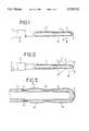
- FIG. 1is a partial axial sectional view of a catheter in accordance with the invention, the balloon not being inflated;
- FIG. 2is a view corresponding to FIG. 1, but with the balloon in an inflated condition;
- FIG. 3is a sectional view on an enlarged scale of the distal end of the catheter illustrated in FIG. 1;
- FIG. 4, FIG. 5 and FIG. 6illustrate three steps of a preferred process and system for manufacturing a catheter according to the present invention.
- the catheter illustrated in FIG. 1 to FIG. 3comprises a catheter body or tube 1 of any known type, suitable for catheters as described herein.
- a preferred material in this regardis an extrudable polymer such as a polyurethane.
- the illustrated catheterincludes a Luer adaptor 2 at one of the tube, which is its proximal end.
- a balloon member 3is positioned at its other end, which is its distal end.
- the balloon member 3is provided in the form of a "bag” presenting an annular opening 4 (FIG. 6) within which the distal end of the catheter body or tube 1 is engaged.
- the sides of the opening 4are mounted on the tube 1.
- the mounting engagementis by interposition of an adhesive ring 5 (FIG. 3) between the inner surface of the balloon member 3 and the outer surface of the catheter tube 1.
- the distal end or tip 6 of the catheter body or tube 1is closed and preferably curved or semi-spherical as illustrated.
- Inflation of the balloon 3is effected by generally known means of the duct or lumen (not shown) of tube 1 and of holes 7 formed in the wall of the tube 1 between the adhesive ring 5 and the blocked or closed distal end or tip 6 of the catheter tube which preferably is in engagement with the balloon, at least prior to inflation.
- the balloon member 3has an annular region 17 of a reduced diameter in a plane approximately perpendicular to the axis of the catheter tube 1 and of the balloon member 3.
- This annular region 17is shown in its inflated state in FIG. 2. It is fixed to the tube 1 only by the adhesive ring 5, so that in its inflated state, its distal end section 8 opposite to its annular opening 4 is detached from the distal end or tip 6 of the tube 1. More specifically, this detached or spaced condition is achieved by having the inflation fluid, such as saline solution or the like, between the respective distal tips of the catheter tube and of the balloon member.
- the inflation fluidsuch as saline solution or the like
- FIG. 4shows a spindle 10 which is plunged into a bath 11, preferably repeatedly, which procedure forms a film onto the spindle 10 as the material of the bath adheres to and forms on the spindle.
- the resultis a balloon 3 having a shape which substantially conforms to the shape of the spindle 10.
- Bath 11is of a material which will form films on surfaces when exposed to air or the like.
- the bathwill be a polymer or polymer forming material within a solvent or carrier that dissipates when the solution of the bath is spread in a thin layer.
- Preferred bath 11is a solution of silicone compound in heptane, which forms a silicone polymer film or layer upon evaporation or dissipation of the heptane.
- the spindlehas an end in the form of a dumbbell or a dogbone, having a reduced diameter annular portion 12.
- the resulting balloonhas the general configuration of the outer surface of the spindle 10, which is the desired shape of the balloon member 3 with its annular restriction or region 17 spaced between and partially defining the two illustrated protuberances or balloon regions 18, each of which have a diameter larger than that of the annular restriction 17, especially when the balloon is inflated, as best seen in FIG. 2.
- Balloon member 3thus obtained is introduced onto a rigid tube 13, as illustrated in FIG. 5. Next, this assembly is placed in a tube 14 where the balloon is inflated by means of a hole 15 in the tube 13. During this phase of the process, this tube 14 avoids or prevents bursting during inflation of the balloon member 3.
- FIG. 6illustrates placement of the thus prepared balloon member 3 on the flexible tube 1 (preferably polyurethane).
- the balloon member 3is longitudinally stretched along the flexible tube 1 and then adhesively attached in an annular manner around its opening 4 in accordance with the preferred embodiment described herein.
- the thus produced cathetertypically is introduced through an endoscope working channel using a guidewire.
- Its balloonis passed through the hole of the third ventricle floor and inflated to render the opening patent.
- Advantageous cushioning with respect to delicate organs at this locationis provided by the inflated distal end of the balloon and its spacing away from the distal tip of the catheter tube.
- the balloonpresents a "waist" at approximately midway along its length to facilitate placing and retaining of the third ventricle membrane between the two balloon protuberances at inflation, thus preventing the balloon from shifting out of the hole.
- a typical balloon for this usehas a length of about 15 mm, a diameter of about 10 mm at the two protuberances, and a diameter of 5 mm at the "waist" or reduced-diameter annular region 17, the diameters being nominal inflation diameters.
Landscapes
- Health & Medical Sciences (AREA)
- Life Sciences & Earth Sciences (AREA)
- Heart & Thoracic Surgery (AREA)
- Engineering & Computer Science (AREA)
- Biophysics (AREA)
- Pulmonology (AREA)
- Child & Adolescent Psychology (AREA)
- Anesthesiology (AREA)
- Biomedical Technology (AREA)
- Hematology (AREA)
- Animal Behavior & Ethology (AREA)
- General Health & Medical Sciences (AREA)
- Public Health (AREA)
- Veterinary Medicine (AREA)
- Media Introduction/Drainage Providing Device (AREA)
Abstract
Description
Claims (16)
Priority Applications (2)
| Application Number | Priority Date | Filing Date | Title |
|---|---|---|---|
| FR9409890AFR2723537B1 (en) | 1994-08-10 | 1994-08-10 | BALLOON CATHETER. |
| US08/513,274US5718712A (en) | 1994-08-10 | 1995-08-10 | Dilatation balloon catheter for endoscopy |
Applications Claiming Priority (2)
| Application Number | Priority Date | Filing Date | Title |
|---|---|---|---|
| FR9409890AFR2723537B1 (en) | 1994-08-10 | 1994-08-10 | BALLOON CATHETER. |
| US08/513,274US5718712A (en) | 1994-08-10 | 1995-08-10 | Dilatation balloon catheter for endoscopy |
Publications (1)
| Publication Number | Publication Date |
|---|---|
| US5718712Atrue US5718712A (en) | 1998-02-17 |
Family
ID=26231350
Family Applications (1)
| Application Number | Title | Priority Date | Filing Date |
|---|---|---|---|
| US08/513,274Expired - LifetimeUS5718712A (en) | 1994-08-10 | 1995-08-10 | Dilatation balloon catheter for endoscopy |
Country Status (2)
| Country | Link |
|---|---|
| US (1) | US5718712A (en) |
| FR (1) | FR2723537B1 (en) |
Cited By (28)
| Publication number | Priority date | Publication date | Assignee | Title |
|---|---|---|---|---|
| US20020133142A1 (en)* | 1999-07-19 | 2002-09-19 | Deniega Jose Castillo | Catheter for uniform delivery of medication |
| US20030236495A1 (en)* | 2002-05-16 | 2003-12-25 | Kennedy Kenneth C. | Non-buckling balloon catheter |
| US20040106901A1 (en)* | 2002-11-30 | 2004-06-03 | Letson William W. | Catheter having a balloon member invertedly attached thereto |
| US20040103518A1 (en)* | 2002-11-30 | 2004-06-03 | Triebes Thomas Gregory | Process for securing a tip member to a catheter during production of the tip member |
| US20040103987A1 (en)* | 2002-11-30 | 2004-06-03 | Triebes Thomas Gregory | Process for producing unitary component and a catheter having a unitary component |
| US20040106899A1 (en)* | 2002-11-30 | 2004-06-03 | Mcmichael Donald J. | Gastric balloon catheter with improved balloon orientation |
| US20040204754A1 (en)* | 2003-04-14 | 2004-10-14 | Anvil Medical, Inc. | Stent for placement at luminal os |
| US20040236366A1 (en)* | 2002-05-16 | 2004-11-25 | Kennedy Kenneth C. | Non-buckling balloon catheter |
| US20050027369A1 (en)* | 2002-05-10 | 2005-02-03 | Eldridge Stephen N. | Prosthetic repair fabric with erosion resistant edge |
| US20050228483A1 (en)* | 2003-04-14 | 2005-10-13 | Kaplan Aaron V | Vascular bifurcation prosthesis with multiple thin fronds |
| US20060025849A1 (en)* | 2003-04-14 | 2006-02-02 | Aaron Kaplan | Vascular bifurcation prosthesis with multiple linked thin fronds |
| US20060064064A1 (en)* | 2004-09-17 | 2006-03-23 | Jang G D | Two-step/dual-diameter balloon angioplasty catheter for bifurcation and side-branch vascular anatomy |
| US20060079952A1 (en)* | 2004-10-13 | 2006-04-13 | Anvil Medical Inc. | Delivery system for placement of prosthesis at luminal os |
| US20070179426A1 (en)* | 2004-05-11 | 2007-08-02 | Selden Nathan R | Interfacial stent and method of maintaining patency of surgical fenestrations |
| US20070213804A1 (en)* | 2003-04-14 | 2007-09-13 | Tryton Medical, Inc. | Kit for treating vascular bifurcations |
| US20070213803A1 (en)* | 2003-04-14 | 2007-09-13 | Tryton Medical, Inc. | Prosthesis and deployment catheter for treating vascular bifurcations |
| US20080109010A1 (en)* | 2006-11-07 | 2008-05-08 | Femsuite, Llc | Apparatus for cervical manipulation and methods of use |
| US20080188803A1 (en)* | 2005-02-03 | 2008-08-07 | Jang G David | Triple-profile balloon catheter |
| US20080306441A1 (en)* | 2007-04-10 | 2008-12-11 | Wilson-Cook Medical Inc. | Non-buckling balloon catheter with spring loaded floating flexible tip |
| US7534224B2 (en) | 2002-11-30 | 2009-05-19 | Kimberly-Clark Worldwide, Inc. | Catheter with unitary component |
| US7547302B2 (en) | 1999-07-19 | 2009-06-16 | I-Flow Corporation | Anti-microbial catheter |
| US20090326641A1 (en)* | 2003-04-14 | 2009-12-31 | Tryton Medical, Inc. | Helical ostium support for treating vascular bifurcations |
| US20110004291A1 (en)* | 2009-07-02 | 2011-01-06 | Tryton Medical, Inc. | Ostium support for treating vascular bifurcations |
| US20110098683A1 (en)* | 2009-10-26 | 2011-04-28 | Wiita Gregory D | Balloon Encapsulated Catheter Tip |
| US20110172520A1 (en)* | 2007-05-15 | 2011-07-14 | Cook Medical Technologies Llc | Multifilar cable catheter |
| US9427142B2 (en) | 2005-08-08 | 2016-08-30 | Smart Medical Systems Ltd | Balloon guided endoscopy |
| US9707108B2 (en) | 2010-11-24 | 2017-07-18 | Tryton Medical, Inc. | Support for treating vascular bifurcations |
| US10500077B2 (en) | 2012-04-26 | 2019-12-10 | Poseidon Medical Inc. | Support for treating vascular bifurcations |
Families Citing this family (2)
| Publication number | Priority date | Publication date | Assignee | Title |
|---|---|---|---|---|
| DE19816829C1 (en)* | 1998-04-16 | 1999-09-30 | Aesculap Ag & Co Kg | Balloon catheter connector |
| IT1395280B1 (en)* | 2009-08-12 | 2012-09-05 | London Equitable Ltd In Its Capacity As Trustee Of The Think Tank Trust | GROUP OF EXPANSION AND RELATED CATHETER OR KIT |
Citations (16)
| Publication number | Priority date | Publication date | Assignee | Title |
|---|---|---|---|---|
| FR439636A (en)* | 1912-02-02 | 1912-06-19 | Louis Marie Clement Charnaux | Expandable catheter for the diagnosis and treatment of bowel, esophagus and urethral disorders |
| US1690995A (en)* | 1927-12-28 | 1928-11-06 | Monte Lloyd Corp | Anorectal dilator |
| US1786373A (en)* | 1929-11-30 | 1930-12-23 | Ralph C Walker | Electrically-heated therapeutical appliance |
| US2849001A (en)* | 1955-10-17 | 1958-08-26 | Vincent J Oddo | Haemostatic catheter |
| US2849002A (en)* | 1956-03-12 | 1958-08-26 | Vincent J Oddo | Haemostatic catheter |
| US3154077A (en)* | 1962-06-04 | 1964-10-27 | Joseph P Cannon | Hemostatic device for anal surgery |
| US3962519A (en)* | 1968-04-26 | 1976-06-08 | Messrs. Willy Rusch, K.G. | Rubber article or instrument and method of producing the same |
| US4137906A (en)* | 1977-05-05 | 1979-02-06 | Koken Co., Ltd. | Catheter apparatus with occlusion and flow diverting means |
| US4213461A (en)* | 1977-09-15 | 1980-07-22 | Pevsner Paul H | Miniature balloon catheter |
| US4327736A (en)* | 1979-11-20 | 1982-05-04 | Kanji Inoue | Balloon catheter |
| US4338943A (en)* | 1979-05-14 | 1982-07-13 | Fuji Latex Co., Ltd. | Instrument for induction of labor |
| US4351342A (en)* | 1981-06-10 | 1982-09-28 | Wiita Bruce E | Balloon catheter |
| SU1060190A1 (en)* | 1982-08-11 | 1983-12-15 | Запорожский Областной Отдел Здравоохранения | Apparatus for expanding the canals of man's body |
| US4986830A (en)* | 1989-09-22 | 1991-01-22 | Schneider (U.S.A.) Inc. | Valvuloplasty catheter with balloon which remains stable during inflation |
| US5355087A (en)* | 1989-02-27 | 1994-10-11 | Medrad, Inc. | Intracavity probe and interface device for MRI imaging and spectroscopy |
| US5360402A (en)* | 1990-01-10 | 1994-11-01 | Rochester Medical Corporation | Hand-actuated retention catheter |
Family Cites Families (1)
| Publication number | Priority date | Publication date | Assignee | Title |
|---|---|---|---|---|
| DE1766265B1 (en)* | 1968-04-26 | 1970-04-02 | Willy Ruesch Kg | Instrument, in particular medical or sanitary instrument, made of rubber and process for its manufacture |
- 1994
- 1994-08-10FRFR9409890Apatent/FR2723537B1/ennot_activeExpired - Fee Related
- 1995
- 1995-08-10USUS08/513,274patent/US5718712A/ennot_activeExpired - Lifetime
Patent Citations (16)
| Publication number | Priority date | Publication date | Assignee | Title |
|---|---|---|---|---|
| FR439636A (en)* | 1912-02-02 | 1912-06-19 | Louis Marie Clement Charnaux | Expandable catheter for the diagnosis and treatment of bowel, esophagus and urethral disorders |
| US1690995A (en)* | 1927-12-28 | 1928-11-06 | Monte Lloyd Corp | Anorectal dilator |
| US1786373A (en)* | 1929-11-30 | 1930-12-23 | Ralph C Walker | Electrically-heated therapeutical appliance |
| US2849001A (en)* | 1955-10-17 | 1958-08-26 | Vincent J Oddo | Haemostatic catheter |
| US2849002A (en)* | 1956-03-12 | 1958-08-26 | Vincent J Oddo | Haemostatic catheter |
| US3154077A (en)* | 1962-06-04 | 1964-10-27 | Joseph P Cannon | Hemostatic device for anal surgery |
| US3962519A (en)* | 1968-04-26 | 1976-06-08 | Messrs. Willy Rusch, K.G. | Rubber article or instrument and method of producing the same |
| US4137906A (en)* | 1977-05-05 | 1979-02-06 | Koken Co., Ltd. | Catheter apparatus with occlusion and flow diverting means |
| US4213461A (en)* | 1977-09-15 | 1980-07-22 | Pevsner Paul H | Miniature balloon catheter |
| US4338943A (en)* | 1979-05-14 | 1982-07-13 | Fuji Latex Co., Ltd. | Instrument for induction of labor |
| US4327736A (en)* | 1979-11-20 | 1982-05-04 | Kanji Inoue | Balloon catheter |
| US4351342A (en)* | 1981-06-10 | 1982-09-28 | Wiita Bruce E | Balloon catheter |
| SU1060190A1 (en)* | 1982-08-11 | 1983-12-15 | Запорожский Областной Отдел Здравоохранения | Apparatus for expanding the canals of man's body |
| US5355087A (en)* | 1989-02-27 | 1994-10-11 | Medrad, Inc. | Intracavity probe and interface device for MRI imaging and spectroscopy |
| US4986830A (en)* | 1989-09-22 | 1991-01-22 | Schneider (U.S.A.) Inc. | Valvuloplasty catheter with balloon which remains stable during inflation |
| US5360402A (en)* | 1990-01-10 | 1994-11-01 | Rochester Medical Corporation | Hand-actuated retention catheter |
Cited By (72)
| Publication number | Priority date | Publication date | Assignee | Title |
|---|---|---|---|---|
| US7547302B2 (en) | 1999-07-19 | 2009-06-16 | I-Flow Corporation | Anti-microbial catheter |
| US8328771B2 (en) | 1999-07-19 | 2012-12-11 | Roger Dillard Massengale | Method for fluid delivery and catheters for use with same |
| US20020133142A1 (en)* | 1999-07-19 | 2002-09-19 | Deniega Jose Castillo | Catheter for uniform delivery of medication |
| US20090093790A1 (en)* | 1999-07-19 | 2009-04-09 | Iflow Corporation | Method of fluid delivery and catheters for use with same |
| US7527609B2 (en)* | 1999-07-19 | 2009-05-05 | I-Flow Corporation | Catheter for uniform delivery of medication |
| US7465291B2 (en) | 1999-07-19 | 2008-12-16 | I-Flow Corporation | Method of fluid delivery and catheters for use with same |
| US20040116896A1 (en)* | 1999-07-19 | 2004-06-17 | Massengale Roger Dillard | Method of fluid delivery and catheters for use with same |
| US8343135B2 (en) | 1999-07-19 | 2013-01-01 | Kimberly-Clark Worldwide, Inc. | Anti-microbial catheter |
| US20090187152A1 (en)* | 1999-07-19 | 2009-07-23 | L-Flow Corporation | Anti-microbial catheter |
| US7959623B2 (en) | 1999-07-19 | 2011-06-14 | I-Flow Corporation | Method of fluid delivery and catheters for use with same |
| AU2009200964B2 (en)* | 1999-07-19 | 2011-09-29 | Avent, Inc. | Catheter for uniform delivery of medication |
| US20050027369A1 (en)* | 2002-05-10 | 2005-02-03 | Eldridge Stephen N. | Prosthetic repair fabric with erosion resistant edge |
| US20030236495A1 (en)* | 2002-05-16 | 2003-12-25 | Kennedy Kenneth C. | Non-buckling balloon catheter |
| US20040236366A1 (en)* | 2002-05-16 | 2004-11-25 | Kennedy Kenneth C. | Non-buckling balloon catheter |
| US7124489B2 (en) | 2002-11-30 | 2006-10-24 | Kimberly-Clark Worldwide, Inc. | Process for producing a catheter |
| US20040106899A1 (en)* | 2002-11-30 | 2004-06-03 | Mcmichael Donald J. | Gastric balloon catheter with improved balloon orientation |
| US7534224B2 (en) | 2002-11-30 | 2009-05-19 | Kimberly-Clark Worldwide, Inc. | Catheter with unitary component |
| US20040103987A1 (en)* | 2002-11-30 | 2004-06-03 | Triebes Thomas Gregory | Process for producing unitary component and a catheter having a unitary component |
| US20040103518A1 (en)* | 2002-11-30 | 2004-06-03 | Triebes Thomas Gregory | Process for securing a tip member to a catheter during production of the tip member |
| US20040106901A1 (en)* | 2002-11-30 | 2004-06-03 | Letson William W. | Catheter having a balloon member invertedly attached thereto |
| US20080039919A1 (en)* | 2003-04-14 | 2008-02-14 | Aaron Kaplan | Prosthesis And Deployment Catheter For Treating Vascular Bifurcations |
| US8529618B2 (en) | 2003-04-14 | 2013-09-10 | Tryton Medical, Inc. | Ostium support for treating vascular bifurcations |
| US9775728B2 (en) | 2003-04-14 | 2017-10-03 | Tryton Medical, Inc. | Vascular bifurcation prosthesis |
| US8876884B2 (en) | 2003-04-14 | 2014-11-04 | Tryton Medical, Inc. | Prosthesis and deployment catheter for treating vascular bifurcations |
| US8672994B2 (en) | 2003-04-14 | 2014-03-18 | Tryton Medical, Inc. | Prosthesis for treating vascular bifurcations |
| US7481834B2 (en) | 2003-04-14 | 2009-01-27 | Tryton Medical, Inc. | Stent for placement at luminal os |
| US8641755B2 (en) | 2003-04-14 | 2014-02-04 | Tryton Medical, Inc. | Prosthesis for treating vascular bifurcations |
| US8641751B2 (en) | 2003-04-14 | 2014-02-04 | Tryton Medical, Inc. | Vascular bifurcation prosthesis with multiple linked thin fronds |
| US20070213803A1 (en)* | 2003-04-14 | 2007-09-13 | Tryton Medical, Inc. | Prosthesis and deployment catheter for treating vascular bifurcations |
| US20070213804A1 (en)* | 2003-04-14 | 2007-09-13 | Tryton Medical, Inc. | Kit for treating vascular bifurcations |
| US7972372B2 (en) | 2003-04-14 | 2011-07-05 | Tryton Medical, Inc. | Kit for treating vascular bifurcations |
| US20090163999A1 (en)* | 2003-04-14 | 2009-06-25 | Tryton Medical, Inc. | Vascular bifurcation prosthesis with multiple linked thin fronds |
| US20090163988A1 (en)* | 2003-04-14 | 2009-06-25 | Tryton Medical, Inc. | Stepped balloon catheter for treating vascular bifurcations |
| US20060025849A1 (en)* | 2003-04-14 | 2006-02-02 | Aaron Kaplan | Vascular bifurcation prosthesis with multiple linked thin fronds |
| US20090326641A1 (en)* | 2003-04-14 | 2009-12-31 | Tryton Medical, Inc. | Helical ostium support for treating vascular bifurcations |
| US20040204754A1 (en)* | 2003-04-14 | 2004-10-14 | Anvil Medical, Inc. | Stent for placement at luminal os |
| US7731747B2 (en) | 2003-04-14 | 2010-06-08 | Tryton Medical, Inc. | Vascular bifurcation prosthesis with multiple thin fronds |
| US7758630B2 (en) | 2003-04-14 | 2010-07-20 | Tryton Medical, Inc. | Helical ostium support for treating vascular bifurcations |
| US20050228483A1 (en)* | 2003-04-14 | 2005-10-13 | Kaplan Aaron V | Vascular bifurcation prosthesis with multiple thin fronds |
| US20100222870A1 (en)* | 2003-04-14 | 2010-09-02 | Tryton Medical, Inc. | Vascular bifurcation prosthesis with at least one frond |
| US8257432B2 (en) | 2003-04-14 | 2012-09-04 | Tryton Medical, Inc. | Vascular bifurcation prosthesis with at least one frond |
| US8187314B2 (en) | 2003-04-14 | 2012-05-29 | Tryton Medical, Inc. | Prothesis and deployment catheter for treating vascular bifurcations |
| US8109987B2 (en) | 2003-04-14 | 2012-02-07 | Tryton Medical, Inc. | Method of treating a lumenal bifurcation |
| US8083791B2 (en) | 2003-04-14 | 2011-12-27 | Tryton Medical, Inc. | Method of treating a lumenal bifurcation |
| US20080183269A2 (en)* | 2003-04-14 | 2008-07-31 | Tryton Medical, Inc. | Prosthesis for treating vascular bifurcations |
| US20070179426A1 (en)* | 2004-05-11 | 2007-08-02 | Selden Nathan R | Interfacial stent and method of maintaining patency of surgical fenestrations |
| US20060064064A1 (en)* | 2004-09-17 | 2006-03-23 | Jang G D | Two-step/dual-diameter balloon angioplasty catheter for bifurcation and side-branch vascular anatomy |
| US20090048655A1 (en)* | 2004-09-17 | 2009-02-19 | Jang G David | Two-step/dual-diameter balloon angioplasty catheter for bifurcation and side-branch vascular anatomy |
| US8926685B2 (en) | 2004-10-13 | 2015-01-06 | Tryton Medical, Inc. | Prosthesis for placement at a luminal OS |
| US7972369B2 (en) | 2004-10-13 | 2011-07-05 | Tryton Medical, Inc. | Method for delivering a luminal prosthesis |
| US20080015610A1 (en)* | 2004-10-13 | 2008-01-17 | Tryton Medical, Inc. | System for delivering a prosthesis to a luminal os |
| US8252038B2 (en) | 2004-10-13 | 2012-08-28 | Tryton Medical, Inc. | System for delivering a prosthesis to a luminal OS |
| US20060079952A1 (en)* | 2004-10-13 | 2006-04-13 | Anvil Medical Inc. | Delivery system for placement of prosthesis at luminal os |
| US20100211160A1 (en)* | 2004-10-13 | 2010-08-19 | Tryton Medical, Inc. | Prosthesis for placement at a luminal os |
| US7717953B2 (en) | 2004-10-13 | 2010-05-18 | Tryton Medical, Inc. | Delivery system for placement of prosthesis at luminal OS |
| US20080188803A1 (en)* | 2005-02-03 | 2008-08-07 | Jang G David | Triple-profile balloon catheter |
| US9427142B2 (en) | 2005-08-08 | 2016-08-30 | Smart Medical Systems Ltd | Balloon guided endoscopy |
| US20080109010A1 (en)* | 2006-11-07 | 2008-05-08 | Femsuite, Llc | Apparatus for cervical manipulation and methods of use |
| US20080306441A1 (en)* | 2007-04-10 | 2008-12-11 | Wilson-Cook Medical Inc. | Non-buckling balloon catheter with spring loaded floating flexible tip |
| US20110172520A1 (en)* | 2007-05-15 | 2011-07-14 | Cook Medical Technologies Llc | Multifilar cable catheter |
| US9199058B2 (en)* | 2007-05-15 | 2015-12-01 | Cook Medical Technologies, LLC | Multifilar cable catheter |
| US9149373B2 (en) | 2009-07-02 | 2015-10-06 | Tryton Medical, Inc. | Method of treating vascular bifurcations |
| US8382818B2 (en) | 2009-07-02 | 2013-02-26 | Tryton Medical, Inc. | Ostium support for treating vascular bifurcations |
| US8366763B2 (en) | 2009-07-02 | 2013-02-05 | Tryton Medical, Inc. | Ostium support for treating vascular bifurcations |
| US20110004291A1 (en)* | 2009-07-02 | 2011-01-06 | Tryton Medical, Inc. | Ostium support for treating vascular bifurcations |
| US8636724B2 (en) | 2009-10-26 | 2014-01-28 | Poiesis Medical, Llc | Balloon encapsulated catheter tip |
| US20110098683A1 (en)* | 2009-10-26 | 2011-04-28 | Wiita Gregory D | Balloon Encapsulated Catheter Tip |
| US20110094655A1 (en)* | 2009-10-26 | 2011-04-28 | Wiita Gregory D | Method For Manufacturing A Balloon Encapsulated Catheter Tip |
| WO2011056587A1 (en)* | 2009-10-26 | 2011-05-12 | Poiesis Medical, Llc | Balloon encapsulated catheter tip |
| US9707108B2 (en) | 2010-11-24 | 2017-07-18 | Tryton Medical, Inc. | Support for treating vascular bifurcations |
| US10500072B2 (en) | 2010-11-24 | 2019-12-10 | Poseidon Medical Inc. | Method of treating vascular bifurcations |
| US10500077B2 (en) | 2012-04-26 | 2019-12-10 | Poseidon Medical Inc. | Support for treating vascular bifurcations |
Also Published As
| Publication number | Publication date |
|---|---|
| FR2723537B1 (en) | 1996-12-27 |
| FR2723537A1 (en) | 1996-02-16 |
Similar Documents
| Publication | Publication Date | Title |
|---|---|---|
| US5718712A (en) | Dilatation balloon catheter for endoscopy | |
| US5545135A (en) | Perfusion balloon stent | |
| EP0376451B1 (en) | Dilatation catheter with fluted balloon | |
| US5188595A (en) | Method for enhanced retention of balloon catheter in body cavity | |
| US5078725A (en) | Balloon catheter and techniques for dilating obstructed lumens and other luminal procedures | |
| KR100818903B1 (en) | Medical device with braid and coil | |
| US4909252A (en) | Perfusion balloon catheter | |
| US5179961A (en) | Catheter guiding and positioning method | |
| US8357138B2 (en) | Angioplasty method and means for performing angioplasty | |
| EP0057205B1 (en) | Calibrating dilatation catheter | |
| EP0456663B1 (en) | An angioplasty catheter and a method of making the same | |
| JP3704355B2 (en) | Esophageal dilatation balloon catheter with flexible Nitinol wire | |
| US5320634A (en) | Balloon catheter with seated cutting edges | |
| EP0249456A2 (en) | Variable diameter catheter | |
| US4624657A (en) | Medical devices having inflatable portions | |
| US5108414A (en) | Techniques for dilating obstructed lumens and other luminal procedures | |
| IL143534A (en) | Endovascular system for the treatment of stenoses of the carotid and catheter for this system | |
| JP2007530159A (en) | Percutaneous introducer balloon | |
| US5054500A (en) | Catheter guiding and positioning method | |
| JPH0229264A (en) | Balloon catheter | |
| US5700242A (en) | Balloon catheter and method for facilitating increased radial expansion | |
| US6805688B2 (en) | Method and device for use in micro-invasive surgical procedures, and guide catheter and valve unit for a device for use in micro-invasive surgical procedures | |
| JP2000051361A (en) | Dilating balloon catheter | |
| US5817053A (en) | Guide catheter exchange device | |
| US11351346B2 (en) | Balloon sheath and associated methods |
Legal Events
| Date | Code | Title | Description |
|---|---|---|---|
| AS | Assignment | Owner name:ELEKTA AB, SWEDEN Free format text:ASSIGNMENT OF ASSIGNORS INTEREST;ASSIGNOR:BONNAL, OLIVIER;REEL/FRAME:008818/0282 Effective date:19971107 Owner name:ELEKTA AB, SWEDEN Free format text:ASSIGNMENT OF ASSIGNORS INTEREST;ASSIGNOR:SAINTE-ROSE, CHRISTIAN;REEL/FRAME:008818/0291 Effective date:19971106 | |
| STCF | Information on status: patent grant | Free format text:PATENTED CASE | |
| AS | Assignment | Owner name:NMT NEUROSCIENCES (IP), INC., A DELAWARE CORPORATI Free format text:ASSIGNMENT OF ASSIGNORS INTEREST;ASSIGNOR:ELEKTA AB (PUBL) A SWEDISH CORPORATION;REEL/FRAME:009375/0712 Effective date:19980708 Owner name:J.H. WHITNEY & CO., CONNECTICUT Free format text:SECURITY INTEREST;ASSIGNORS:NITINOL MEDICAL TECHNOLOGIES, INC.;NMT NEUROSCIENCES (IP) INC.;NMT NEUROSCIENCES (INTERNATIONAL) INC.;AND OTHERS;REEL/FRAME:009375/0116 Effective date:19980708 | |
| AS | Assignment | Owner name:NMT MEDICAL, INC., MASSACHUSETTS Free format text:CHANGE OF NAME;ASSIGNOR:NMT NEUROSCIENCES (IP), INC. (A DELAWARE CORPORATION);REEL/FRAME:010206/0089 Effective date:19990603 | |
| AS | Assignment | Owner name:BROWN BROTHERS HARRIMAN & CO., MASSACHUSETTS Free format text:COLLATERAL ASSIGNMENT;ASSIGNOR:NMT MEDICAL, INC. F/K/A NITINOL MEDICAL TECHNOLOGIES, INC.;REEL/FRAME:010247/0919 Effective date:19990913 | |
| AS | Assignment | Owner name:NMT NEUROSCIENCES (INTERNATIONAL), INC., MASSACHUS Free format text:SECURITY INTEREST TERMINATION;ASSIGNOR:J.H. WHITNEY & CO.;REEL/FRAME:010668/0425 Effective date:19991020 Owner name:NMT INVESTMENTS CORP., MASSACHUSETTS Free format text:SECURITY INTEREST TERMINATION;ASSIGNOR:J.H. WHITNEY & CO.;REEL/FRAME:010668/0425 Effective date:19991020 Owner name:NMT NEUROSCIENCES (U.S.), INC., MASSACHUSETTS Free format text:SECURITY INTEREST TERMINATION;ASSIGNOR:J.H. WHITNEY & CO.;REEL/FRAME:010668/0425 Effective date:19991020 Owner name:NMT NEUROSCIENCES (IP), INC., MASSACHUSETTS Free format text:SECURITY INTEREST TERMINATION;ASSIGNOR:J.H. WHITNEY & CO.;REEL/FRAME:010668/0425 Effective date:19991020 Owner name:NMT HEART, INC., MASSACHUSETTS Free format text:SECURITY INTEREST TERMINATION;ASSIGNOR:J.H. WHITNEY & CO.;REEL/FRAME:010668/0425 Effective date:19991020 Owner name:NMT MEDICAL, INC. (F/K/A NITINOL MEDICAL TECHNOLOG Free format text:SECURITY INTEREST TERMINATION;ASSIGNOR:J.H. WHITNEY & CO.;REEL/FRAME:010668/0425 Effective date:19991020 Owner name:NMT NEUROSCIENCES INNOVASIVE SYSTEMS, INC. (F/K/A Free format text:SECURITY INTEREST TERMINATION;ASSIGNOR:J.H. WHITNEY & CO.;REEL/FRAME:010668/0425 Effective date:19991020 | |
| FEPP | Fee payment procedure | Free format text:PAT HOLDER CLAIMS SMALL ENTITY STATUS - SMALL BUSINESS (ORIGINAL EVENT CODE: SM02); ENTITY STATUS OF PATENT OWNER: LARGE ENTITY | |
| AS | Assignment | Owner name:BROWN BROTHERS HARRIMAN & CO., MASSACHUSETTS Free format text:SECURITY INTEREST TERMINATION RECORDED AT REEL 10247 FRAME 0919;ASSIGNOR:NMT MEDICAL, INC.;REEL/FRAME:011675/0812 Effective date:20010404 | |
| FPAY | Fee payment | Year of fee payment:4 | |
| AS | Assignment | Owner name:NMT NEUROSCIENCES (IP), INC., DELAWARE Free format text:ASSIGNMENT OF ASSIGNORS INTEREST;ASSIGNOR:NMT MEDICAL, INC.;REEL/FRAME:013036/0168 Effective date:20020730 | |
| REMI | Maintenance fee reminder mailed | ||
| FPAY | Fee payment | Year of fee payment:8 | |
| SULP | Surcharge for late payment | Year of fee payment:7 | |
| FEPP | Fee payment procedure | Free format text:PAT HOLDER NO LONGER CLAIMS SMALL ENTITY STATUS, ENTITY STATUS SET TO UNDISCOUNTED (ORIGINAL EVENT CODE: STOL); ENTITY STATUS OF PATENT OWNER: LARGE ENTITY | |
| FPAY | Fee payment | Year of fee payment:12 |